Original Operating Instructions V-VGA / V-VGC - Elmo Rietschle
Original Operating Instructions V-VGA / V-VGC - Elmo Rietschle
Original Operating Instructions V-VGA / V-VGC - Elmo Rietschle

Create successful ePaper yourself
Turn your PDF publications into a flip-book with our unique Google optimized e-Paper software.
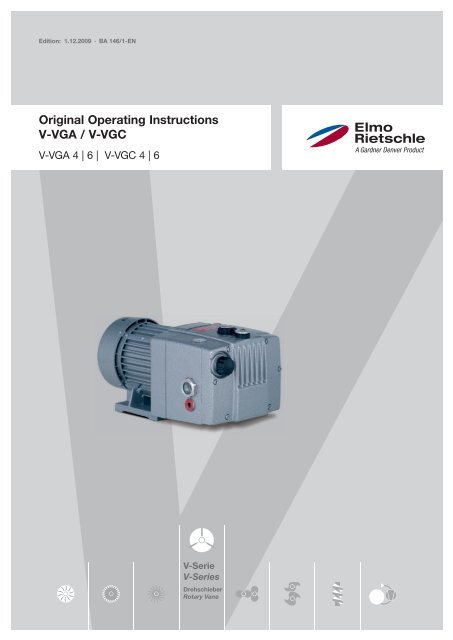
Edition: 1.12.2009 · BA 146/1-EN<br />
<strong>Original</strong> <strong>Operating</strong> <strong>Instructions</strong><br />
V-<strong>VGA</strong> / V-<strong>VGC</strong><br />
V-<strong>VGA</strong> 4 | 6 | V-<strong>VGC</strong> 4 | 6<br />
V-Serie<br />
V-Series<br />
Drehschieber<br />
Rotary Vane
Table of contents<br />
2<br />
Table of contents<br />
1 Foreword . . . . . . . . . . . . . . . . . . . . . . . . . . . . . . . . . . . . . . . . . . . . . . . . . . . . . . . . . . . . . . . . . . . 4<br />
1.1 Principles . . . . . . . . . . . . . . . . . . . . . . . . . . . . . . . . . . . . . . . . . . . . . . . . . . . . . . . . . . . . . . . . . . . 4<br />
1.2 Target group . . . . . . . . . . . . . . . . . . . . . . . . . . . . . . . . . . . . . . . . . . . . . . . . . . . . . . . . . . . . . . . . . 4<br />
1.3 Supplier documentation and accompanying documents . . . . . . . . . . . . . . . . . . . . . . . . . . . . . . 4<br />
1.4 Abbreviations . . . . . . . . . . . . . . . . . . . . . . . . . . . . . . . . . . . . . . . . . . . . . . . . . . . . . . . . . . . . . . . . 4<br />
1.5 Directives, standards, laws . . . . . . . . . . . . . . . . . . . . . . . . . . . . . . . . . . . . . . . . . . . . . . . . . . . . . 4<br />
1.6 Symbols and meaning . . . . . . . . . . . . . . . . . . . . . . . . . . . . . . . . . . . . . . . . . . . . . . . . . . . . . . . . . 5<br />
1.7 Technical terms and meaning . . . . . . . . . . . . . . . . . . . . . . . . . . . . . . . . . . . . . . . . . . . . . . . . . . . 5<br />
1.8 Copyright . . . . . . . . . . . . . . . . . . . . . . . . . . . . . . . . . . . . . . . . . . . . . . . . . . . . . . . . . . . . . . . . . . . 5<br />
2 Safety . . . . . . . . . . . . . . . . . . . . . . . . . . . . . . . . . . . . . . . . . . . . . . . . . . . . . . . . . . . . . . . . . . . . . 6<br />
2.1 Warning instruction markings . . . . . . . . . . . . . . . . . . . . . . . . . . . . . . . . . . . . . . . . . . . . . . . . . . . 6<br />
2.2 General . . . . . . . . . . . . . . . . . . . . . . . . . . . . . . . . . . . . . . . . . . . . . . . . . . . . . . . . . . . . . . . . . . . . . 6<br />
2.3 Designated use . . . . . . . . . . . . . . . . . . . . . . . . . . . . . . . . . . . . . . . . . . . . . . . . . . . . . . . . . . . . . . 7<br />
2.4 Unacceptable operating modes . . . . . . . . . . . . . . . . . . . . . . . . . . . . . . . . . . . . . . . . . . . . . . . . . . 7<br />
2.5 Personal qualifi cations and training . . . . . . . . . . . . . . . . . . . . . . . . . . . . . . . . . . . . . . . . . . . . . . . 8<br />
2.6 Safety-conscious work . . . . . . . . . . . . . . . . . . . . . . . . . . . . . . . . . . . . . . . . . . . . . . . . . . . . . . . . 8<br />
2.7 Safety notes for the operator . . . . . . . . . . . . . . . . . . . . . . . . . . . . . . . . . . . . . . . . . . . . . . . . . . . . 8<br />
2.8 Safety instructions for installing, commissioning and maintenance . . . . . . . . . . . . . . . . . . . . . . 9<br />
2.9 Guarantee conditions . . . . . . . . . . . . . . . . . . . . . . . . . . . . . . . . . . . . . . . . . . . . . . . . . . . . . . . . . . 9<br />
3 Transport, storage and disposal . . . . . . . . . . . . . . . . . . . . . . . . . . . . . . . . . . . . . . . . . . . . . . . . 10<br />
3.1 Transportation . . . . . . . . . . . . . . . . . . . . . . . . . . . . . . . . . . . . . . . . . . . . . . . . . . . . . . . . . . . . . . . 10<br />
3.1.1 Unpack and check the delivery condition . . . . . . . . . . . . . . . . . . . . . . . . . . . . . . . . . . 10<br />
3.1.2 Lifting and transporting . . . . . . . . . . . . . . . . . . . . . . . . . . . . . . . . . . . . . . . . . . . . . . . . . 10<br />
3.2 Storage . . . . . . . . . . . . . . . . . . . . . . . . . . . . . . . . . . . . . . . . . . . . . . . . . . . . . . . . . . . . . . . . . . . . . 11<br />
3.2.1 Ambient conditions for storage . . . . . . . . . . . . . . . . . . . . . . . . . . . . . . . . . . . . . . . . . . 11<br />
3.3 Disposal . . . . . . . . . . . . . . . . . . . . . . . . . . . . . . . . . . . . . . . . . . . . . . . . . . . . . . . . . . . . . . . . . . . . 11<br />
4 Set up and operation . . . . . . . . . . . . . . . . . . . . . . . . . . . . . . . . . . . . . . . . . . . . . . . . . . . . . . . . . 12<br />
4.1 Setup . . . . . . . . . . . . . . . . . . . . . . . . . . . . . . . . . . . . . . . . . . . . . . . . . . . . . . . . . . . . . . . . . . . . . . 12<br />
4.1.1 Data plate . . . . . . . . . . . . . . . . . . . . . . . . . . . . . . . . . . . . . . . . . . . . . . . . . . . . . . . . . . . 13<br />
4.2 Description . . . . . . . . . . . . . . . . . . . . . . . . . . . . . . . . . . . . . . . . . . . . . . . . . . . . . . . . . . . . . . . . . 13<br />
4.3. Areas of application . . . . . . . . . . . . . . . . . . . . . . . . . . . . . . . . . . . . . . . . . . . . . . . . . . . . . . . . . . . . . . . 13<br />
5 Installation . . . . . . . . . . . . . . . . . . . . . . . . . . . . . . . . . . . . . . . . . . . . . . . . . . . . . . . . . . . . . . . . . 14<br />
5.1 Preparing for installation . . . . . . . . . . . . . . . . . . . . . . . . . . . . . . . . . . . . . . . . . . . . . . . . . . . . . . . 14<br />
5.2 Installation . . . . . . . . . . . . . . . . . . . . . . . . . . . . . . . . . . . . . . . . . . . . . . . . . . . . . . . . . . . . . . . . . . 14<br />
5.3 Connecting pipes . . . . . . . . . . . . . . . . . . . . . . . . . . . . . . . . . . . . . . . . . . . . . . . . . . . . . . . . . . . . . 15<br />
5.4 Filling with lubricating oil . . . . . . . . . . . . . . . . . . . . . . . . . . . . . . . . . . . . . . . . . . . . . . . . . . . . . . . 15<br />
5.5 Connecting the motor . . . . . . . . . . . . . . . . . . . . . . . . . . . . . . . . . . . . . . . . . . . . . . . . . . . . . . . . . 16<br />
6 Commissioning and decommissioning . . . . . . . . . . . . . . . . . . . . . . . . . . . . . . . . . . . . . . . . . . 17<br />
6.1 Commissioning . . . . . . . . . . . . . . . . . . . . . . . . . . . . . . . . . . . . . . . . . . . . . . . . . . . . . . . . . . . . . . 17<br />
6.1.1 Checking the rotation direction. . . . . . . . . . . . . . . . . . . . . . . . . . . . . . . . . . . . . . . . . . . 18<br />
6.2 Decommissioning/ storing . . . . . . . . . . . . . . . . . . . . . . . . . . . . . . . . . . . . . . . . . . . . . . . . . . . . . . 18<br />
6.3 Re-commissioning . . . . . . . . . . . . . . . . . . . . . . . . . . . . . . . . . . . . . . . . . . . . . . . . . . . . . . . . . . . . 18<br />
| www.gd-elmorietschle.com © Gardner Denver Schopfheim GmbH, Gardner Denver Deutschland GmbH
Table of contents<br />
7 Maintenance and repair . . . . . . . . . . . . . . . . . . . . . . . . . . . . . . . . . . . . . . . . . . . . . . . . . . . . . . . 19<br />
7.1 Maintenance work . . . . . . . . . . . . . . . . . . . . . . . . . . . . . . . . . . . . . . . . . . . . . . . . . . . . . . . . . . . . 19<br />
7.2 Maintenance work . . . . . . . . . . . . . . . . . . . . . . . . . . . . . . . . . . . . . . . . . . . . . . . . . . . . . . . . . . . . 19<br />
7.2.1 Air fi ltering . . . . . . . . . . . . . . . . . . . . . . . . . . . . . . . . . . . . . . . . . . . . . . . . . . . . . . . . . . . 20<br />
7.2.2 Lubricatio . . . . . . . . . . . . . . . . . . . . . . . . . . . . . . . . . . . . . . . . . . . . . . . . . . . . . . . . . . . 20<br />
7.2.3 Oil removal . . . . . . . . . . . . . . . . . . . . . . . . . . . . . . . . . . . . . . . . . . . . . . . . . . . . . . . . . . 21<br />
7.3 Repair/ Service . . . . . . . . . . . . . . . . . . . . . . . . . . . . . . . . . . . . . . . . . . . . . . . . . . . . . . . . . . . . . . . 22<br />
7.4 Spare parts . . . . . . . . . . . . . . . . . . . . . . . . . . . . . . . . . . . . . . . . . . . . . . . . . . . . . . . . . . . . . . . . . . 23<br />
8 Malfunctions: Causes and elimination . . . . . . . . . . . . . . . . . . . . . . . . . . . . . . . . . . . . . . . . . . . 24<br />
9 Technical Data . . . . . . . . . . . . . . . . . . . . . . . . . . . . . . . . . . . . . . . . . . . . . . . . . . . . . . . . . . . . . . 27<br />
www.gd-elmorietschle.com © Gardner Denver Schopfheim GmbH, Gardner Denver Deutschland GmbH |<br />
3
Foreword<br />
1 Foreword<br />
1.1 Principles<br />
1.2 Target group<br />
1.3 Supplier documentation and accompanying documents<br />
4<br />
These operating instructions:<br />
| www.gd-elmorietschle.com © Gardner Denver Schopfheim GmbH, Gardner Denver Deutschland GmbH<br />
• are a part of the following oil-fl ooded rotary vane<br />
vacuum pumps, V-<strong>VGA</strong> 4, V-<strong>VGA</strong> 6, V-<strong>VGC</strong> 4 and<br />
V-<strong>VGC</strong> 6.<br />
• describe how to use them safely and properly in<br />
all life phases.<br />
• must be available where the equipment is used.<br />
The target group for these instructions is technically<br />
trained specialists.<br />
Document Contents No.<br />
Supplier documentation<br />
<strong>Operating</strong> <strong>Instructions</strong> BA 146/1-EN<br />
Declaration of Conformity C 0036-EN<br />
Declaration of harmlessness 7.7025.003.17<br />
Spare parts’ list Spare parts document E 146<br />
Data sheet Technical data and graphs D 146/1 / D 147/1<br />
Info sheet<br />
Water vapour compatibility for oil-fl ooded<br />
vacuum pumps<br />
I 200<br />
Info sheet Storage guidelines for machines I 150<br />
Manufacturer’s declaration EU Directive 2002/95/EG (RoHS) —<br />
1.4 Abbreviations<br />
1.5 Directives, standards, laws<br />
Fig. Figure<br />
V-<strong>VGA</strong> / V-<strong>VGC</strong><br />
Vacuum pump<br />
m3 /h Pumping capacity<br />
mbar (abs.) Final vacuum, operating vacuum<br />
See Conformity Declaration
1.6 Symbols and meaning<br />
Symbol Explanation<br />
Condition, pre-requisite<br />
#### <strong>Instructions</strong>, action<br />
a), b),... <strong>Instructions</strong> in several steps<br />
Results<br />
[-> 14] Cross reference with page number<br />
1.7 Technical terms and meaning<br />
Information, note<br />
Term Explanation<br />
www.gd-elmorietschle.com © Gardner Denver Schopfheim GmbH, Gardner Denver Deutschland GmbH |<br />
Foreword<br />
Safety symbol<br />
Warns of potential risk of injury<br />
Obey all the safety instructions with this symbol in order to avoid injury<br />
and death.<br />
Machines Pump and motor combination ready to be connected<br />
Motor Pump drive motor<br />
Vacuum pump Machine to create a vacuum<br />
Rotary vane Machine’s design or active principle<br />
Vacuum pump volume fl ow related to the condition in the suction con-<br />
Pumping capacity<br />
nection<br />
Final pressure (abs.) The maximum vacuum that a pump reaches when the suction opening is<br />
closed. Given as absolute pressure.<br />
Permanent vacuum The vacuum or the suction range at which the pump operates permanently.<br />
The permanent vacuum or intake pressure is ≥ than the fi nal vacuum and<br />
< than the atmospheric pressure.<br />
Noise emission<br />
1.8 Copyright<br />
The noise emitted at a specifi c loading given as a fi gure, sound pressure<br />
level dB(A) as per EN ISO 3744..<br />
Passing on or copying this document, using and<br />
providing information on its contents are prohibited<br />
unless expressly permitted.<br />
5
Safety<br />
2 Safety<br />
2.1 Warning instruction markings<br />
6<br />
| www.gd-elmorietschle.com © Gardner Denver Schopfheim GmbH, Gardner Denver Deutschland GmbH<br />
The manufacturer is not responsible for damage if<br />
you do not follow all of this documentation.<br />
Warning Danger level Consequences if not obeyed<br />
DANGER immediately imminent danger Death, severe bodily injury<br />
WARNING possible imminent danger Death, severe bodily injury<br />
CAUTION possible hazardous situation Slight bodily injury<br />
NOTICE possible hazardous situation Material damage<br />
2.2 General<br />
These operating instructions contain basic instructions<br />
for installation, commissioning, maintenance<br />
and inspection work which must be obeyed to ensure<br />
the safe operation of the machine and prevent<br />
physical and material damage.<br />
The safety instructions in all sections must be taken<br />
into consideration.<br />
The operating instructions must be read by the<br />
responsible technical personnel/ operator before<br />
installing and commissioning and must be fully understood.<br />
The contents of the operating instructions<br />
must always be available on site for the technical<br />
personnel / operator. <strong>Instructions</strong> fi xed directly onto<br />
the machine must be obeyed and must always remain<br />
legible. This applies for example to:<br />
• Symbols for connections<br />
• Data and motor data plate<br />
• Instruction and warning plates<br />
The operator is responsible for observing local regulations.
2.3 Designated use<br />
2.4 Unacceptable operating modes<br />
www.gd-elmorietschle.com © Gardner Denver Schopfheim GmbH, Gardner Denver Deutschland GmbH |<br />
Safety<br />
The machine must only be operated in such areas<br />
as are described in the operating instructions:<br />
• only operate the machine in a technically perfect<br />
condition<br />
• do not operate the machine when it is only partially<br />
assembled<br />
• the machine must only be operated at an ambient<br />
temperature and a suction temperature of<br />
between 12 and 40°C<br />
Please contact us for temperatures outside this<br />
range.<br />
• the machine may convey, compress or extract<br />
the following media:<br />
• Air<br />
The air extracted may contain water vapour<br />
but no water or other liquids. For water vapour<br />
compatibility see Info I 200<br />
• all non-explosive, non-infl ammable, non-aggressive<br />
and non-poisonous dry gases and<br />
gas air mixtures<br />
• extracting, conveying and compressing explosive,<br />
infl ammable, aggressive or poisonous media,<br />
e.g. dust as per ATEX zone 20-22, solvents<br />
as well as gaseous oxygen and other oxidants<br />
• extracting, conveying and compressing explosive,<br />
infl ammable, aggressive, oxidative or<br />
poisonous media, e.g. dust as per ATEX zone<br />
20-22, solvents<br />
• using the machine in non-commercial plants if<br />
the necessary precautions and protective measures<br />
have not been taken in the plant<br />
• installing in environments that are at risk of explosions<br />
• using the machine in areas with ionising radiation<br />
• back pressures on the outlet side of more than<br />
+0,1bars<br />
• modifi cations to the machine and accessories<br />
7
Safety<br />
2.5 Personal qualifi cations and training<br />
2.6 Safety-conscious work<br />
2.7 Safety notes for the operator<br />
8<br />
| www.gd-elmorietschle.com © Gardner Denver Schopfheim GmbH, Gardner Denver Deutschland GmbH<br />
• Ensure that people entrusted with working on<br />
the machine have read and understood these<br />
operating instructions before starting work,<br />
particularly the safety instructions for installation,<br />
commissioning, maintenance and inspection<br />
work.<br />
• Manage the responsibilities, competence and<br />
monitoring of staff<br />
• all work must only be carried out be technical<br />
specialists:<br />
• Installation, commissioning, maintenance<br />
and inspection work<br />
• Working with electricity<br />
• personnel being trained to work on the machine<br />
must be supervised by technical specialists<br />
only<br />
The following safety regulations apply in addition<br />
to the safety instructions and intended use listed in<br />
these instructions:<br />
• Accident prevention regulations, safety and operating<br />
regulations<br />
• the standards and laws in force<br />
• hot parts of the machine must not be accessible<br />
during operation or must be fi tted with a guard<br />
• eople must not be endangered by the free extraction<br />
or discharge of pumped media<br />
• Risks arising from electrical energy must be<br />
eliminated.
2.8 Safety instructions for installing, commissioning and maintenance<br />
2.9 Guarantee conditions<br />
www.gd-elmorietschle.com © Gardner Denver Schopfheim GmbH, Gardner Denver Deutschland GmbH |<br />
Safety<br />
• The operator will ensure that any installation,<br />
commissioning and maintenance work is carried<br />
out by authorised, qualifi ed specialists who<br />
have gained suffi cient information by an in-depth<br />
study of the operating instructions.<br />
• Only work on the machine when it is idle and<br />
cannot be switched on again<br />
• Ensure that you follow the procedure for decommissioning<br />
the machine described in the operating<br />
instructions.<br />
• Fit or start up safety and protective devices<br />
again immediately after fi nishing work. Vor Wiederinbetriebnahme<br />
die aufgeführten Punkte für<br />
die Inbetriebnahme beachten<br />
• Conversion work or modifi cations to the machine<br />
are only permissible with the manufacturer’s<br />
consent.<br />
• Only use original parts or parts approved by the<br />
manufacturer. The use of other parts may invalidate<br />
liability for any consequences arising.<br />
• Keep unauthorised people away from the machine<br />
The manufacturer’s guarantee or warranty will no<br />
longer apply in the following cases:<br />
• Improper use<br />
• Not complying with these instructions<br />
• Operation by insuffi ciently qualifi ed staff<br />
• Using spare parts that have not been approved<br />
by Gardner Denver Schopfheim GmbH<br />
• Unauthorised modifi cations to the machine or<br />
the accessories supplied by Gardner Denver<br />
Schopfheim GmbH<br />
9
Transport, storage and disposal<br />
3 Transport, storage and disposal<br />
3.1 Transportation<br />
3.1.1 Unpack and check the delivery condition<br />
3.1.2 Lifting and transporting<br />
10 | www.gd-elmorietschle.com © Gardner Denver Schopfheim GmbH, Gardner Denver Deutschland GmbH<br />
a) Unpack the machine on receipt and check for<br />
transport damage..<br />
b) Notify the manufacturer of transport damage immediately..<br />
c) Dispose of the packaging in accordance with the<br />
local regulations in force.<br />
WARNING<br />
Hurt or limbs crushed as a result of the items<br />
being transported falling or tipping over.<br />
When transporting ensure:<br />
a) that the machine is secured against tipping and<br />
falling.<br />
b) Put the goods to be conveyed on a horizontal<br />
base.
3.2 Storage<br />
3.2.1 Ambient conditions for storage<br />
3.3 Disposal<br />
WARNING<br />
Transport, storage and disposal<br />
Material damage caused by improper storage.<br />
Ensure that the storage area meets the following<br />
conditions:<br />
a) dust free<br />
b) vibration free<br />
Ambient conditions Value<br />
Relative Feuchte 0% to 80%<br />
Storage temperature -10°C to +60°C<br />
For long-term storage (more than 3 months), it is<br />
useful to use a preservation oil rather than operating<br />
oil.<br />
See Info “Machine storage guidelines” I 150<br />
WARNING<br />
Danger from infl ammable, corrosive or poisonous<br />
substances<br />
Machines that come into contact with hazardous<br />
substances must be decontaminated before<br />
disposal<br />
When disposing ensure the following:<br />
a) Collect oils and grease separately and dispose<br />
of in accordance with the local regulations in<br />
force.<br />
b) Do not mix solvents, limescale removers and<br />
paint residues.<br />
c) Remove components and dispose of them in<br />
accordance with the local regulations in force.<br />
d) Dispose of the machine in accordance with the<br />
national and local regulations in force.<br />
e) Parts subject to wear and tear (marked as such<br />
in the spare parts list) are special waste and<br />
must be disposed of in accordance with the<br />
national and local waste laws.<br />
www.gd-elmorietschle.com © Gardner Denver Schopfheim GmbH, Gardner Denver Deutschland GmbH |<br />
11
Set up and operation<br />
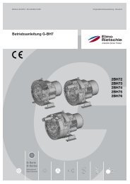
4 Set up and operation<br />
4.1 Setup<br />
D<br />
T<br />
B<br />
A<br />
E<br />
Q<br />
Q<br />
12 | www.gd-elmorietschle.com © Gardner Denver Schopfheim GmbH, Gardner Denver Deutschland GmbH<br />
F<br />
M<br />
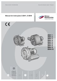
Fig. 1 Vacuum pump V-<strong>VGA</strong> / V-<strong>VGC</strong><br />
A Vacuum connection<br />
B Silencer/ exhaust air outlet<br />
D Filter<br />
E Cooling air inlet<br />
F Cooling air outlet<br />
H Oil fi lling point<br />
I Oil sight glass<br />
K Oil discharge point<br />
M Oil recommendation plate<br />
O<br />
N<br />
K I<br />
F<br />
Q<br />
P<br />
A<br />
U<br />
K I<br />
Q<br />
H<br />
B<br />
N Data plate<br />
O Rotation direction plate<br />
P Drive motor<br />
P1 Motor data plate<br />
Q hot surfaces > 70 °C<br />
T Oil reservoir cove<br />
U Gas ballast valve V-<strong>VGA</strong> (accessory)<br />
Q
4.1.1 Data plate<br />
Typ VC 75 (20)<br />
EN 60034<br />
S1 1,85 / 2,20 kW<br />
10<br />
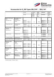
Fig. 2 Data plate (example)<br />
9<br />
4.2 Description<br />
1<br />
Bauj./Nr. 09<br />
2847746<br />
1026502067<br />
0,5 mbar (abs.)<br />
70 / 84 m³/h<br />
1430 / 1720 min -1<br />
8<br />
2<br />
3 4 5<br />
3~ Mot.<br />
7<br />
6<br />
Set up and operation<br />
The V-<strong>VGA</strong> and V-<strong>VGC</strong> have a fi ne micro fi lter on the suction side and on the outlet side an oil and oil mist<br />
separator to return the oil to the oil circulation system. The motor fan provides cooling for the motor and<br />
pump housing. The motor and the pump have a common shaft.<br />
An integral non-return valve prevents the evacuated system from being ventilated after the pump has<br />
stopped and it prevents the feed chamber from being saturated with oil after the system has stopped. This<br />
would lead to oil knocking when the system started up again.<br />
A gas ballast valve (an option with V-<strong>VGA</strong>) prevents condensation of water vapour in the inside of the pump<br />
when low amounts of steam are sucked in when the pump is at operating temperature.<br />
4.3. Areas of application<br />
1 Type/ Size (mechanical version)<br />
2 Year of construction<br />
3 Motor design<br />
4 Serial number<br />
5 Item no.<br />
6 Final pressure (abs.)<br />
7 Pumping capacity 50 Hz/60 Hz<br />
8 Speed 50 Hz/60 Hz<br />
9 Motor output 50 Hz/60 Hz<br />
10 <strong>Operating</strong> mode<br />
These oil-fl ooded rotary vane vacuum pumps V-<strong>VGA</strong> 4, V-<strong>VGA</strong> 6, V-<strong>VGC</strong> 4 and V-<strong>VGC</strong> 6 are suitable for creating<br />
vacuums. The suction power with unrestricted suction is 4 and 6 m3 /h at 50 Hz. Data sheets D 146/1<br />
(V-<strong>VGA</strong>) and D147/1 (V-<strong>VGC</strong>) show the dependency of the suction power on the inlet pressure.<br />
The models are suitable for evacuating closed systems or for a constant vacuum in the following intake<br />
pressure ranges:<br />
50 Hz ➝ V-<strong>VGA</strong>: 20 to 500 mbars (abs.) • V-<strong>VGC</strong>: 2 to 200 mbars (abs.)<br />
60 Hz ➝ V-<strong>VGA</strong>: 20 to 400 mbars (abs.) • V-<strong>VGC</strong>: 2 to 150 mbars (abs.)<br />
If operated constantly outside these ranges there is the risk of oil leaking through the outlet. When evacuating<br />
closed systems the volume to be evacuated must be no more than 2% of the nominal pumping capacity<br />
of the vacuum pump.<br />
If the unit is switched on more frequently (at regular intervals of about 10 times an hour) or at<br />
higher ambient temperatures and intake temperatures, the excess temperature limit of the motor<br />
winding and the bearings may be exceeded.Please contact the manufacturer should the unit be<br />
used under such conditions.<br />
If it is installed in the open air the unit must be protected from environmental infl uences, (e.g. by a<br />
protective roof).<br />
www.gd-elmorietschle.com © Gardner Denver Schopfheim GmbH, Gardner Denver Deutschland GmbH |<br />
13
Installation<br />
5 Installation<br />
5.1 Preparing for installation<br />
5.2 Installation<br />
Check the following points:<br />
14 | www.gd-elmorietschle.com © Gardner Denver Schopfheim GmbH, Gardner Denver Deutschland GmbH<br />
• Machine freely accessible from all sides<br />
• Do not close ventilation grids and holes<br />
• Suffi cient room for installing and removing pipes<br />
and for maintenance work, particularly for installing<br />
and dismantling the machine<br />
• No external vibration effects<br />
• Do not suck any hot exhaust air from other machines<br />
into the cooling system.<br />
The oil fi lling pointFig. 1/H), oil sight glass (Fig. 1/I) and oil outlet Fig. 1/K) must be easily accessible.<br />
The cooling air inlets (Fig. 1/E) and the cooling air outlets (Fig. 1/F) must be at least 15 cm away<br />
from adjacent walls. Cooling air coming out must not be sucked in again. For maintenance work<br />
there must be 30 cm in front of the fi lter (Fig. 1/D) and the oil reservoir cover (Fig. 1/T).<br />
NOTICE<br />
The machine may only be operated when it is<br />
set up horizontally.<br />
Material damage resulting from the machine<br />
tipping over and falling.<br />
When installed at more than 1000 m above sea<br />
level a reduction in power is noticeable. In this<br />
case we would ask you to contact us<br />
Ensure that the foundation complies with the following<br />
conditions:<br />
• Level and straight<br />
• The bearing surface must be at least the same<br />
size as the machine<br />
• The bearing surface must be able to bear the<br />
weight of the machine<br />
It must be possible to install the machine on a fi rm foundation without anchoring. When installing on<br />
a substructure we recommend fi xing with fl exible buffers..
5.3 Connecting pipes<br />
5.4 Filling with lubricating oil<br />
NOTICE<br />
Installation<br />
Material damage resulting from the forces and<br />
torques of the pipes on the unit being too high<br />
Only screw pipes in by hand..<br />
The pumping capacity of the vacuum pump<br />
is reduced if the suction pipe is too narrow<br />
and/or too long.<br />
The air vent (Fig. 1/B) must not be closed or<br />
restricted.<br />
Counter pressures on the outlet side are only<br />
permissible up to + 0.1 bars.<br />
Prevent liquids accumulating in the exhaust<br />
line<br />
a) The vacuum connection at (Fig. 1/A).<br />
b) The air handled can be exhausted into the atmosphere<br />
through the silencer (Fig. 1/B).<br />
a) Fill the lubricating oil (for suitable types see the<br />
„Maintenance“ section) via the oil fi lling point<br />
(Fig. 1/H) up to the upper edge of the sight glass<br />
(Fig. 1/I).<br />
b) Close the oil fi lling point.<br />
www.gd-elmorietschle.com © Gardner Denver Schopfheim GmbH, Gardner Denver Deutschland GmbH |<br />
15
Installation<br />
5.5 Connecting the motor<br />
DANGER<br />
16 | www.gd-elmorietschle.com © Gardner Denver Schopfheim GmbH, Gardner Denver Deutschland GmbH<br />
Danger of death if the electrical installation has<br />
not been done professionally!<br />
The electrical installation must only be done by a<br />
qualifi ed electrician observing EN 60204. The operating<br />
company has to provide the main switch.<br />
a) The electrical motor data can be found on the<br />
data plate (Fig. 1/N). The motors comply with<br />
DIN EN 60034 and are in protection class IP 55<br />
and insulation class F. The appropriate connection<br />
diagram is located in the motor‘s terminal<br />
box (not for the plug connection version). The<br />
motor data must be compared with the data<br />
of the existing mains network (current type,<br />
voltage, network frequency, permitted current<br />
value)..<br />
b) Connect the motor via the motor protection<br />
switch (for safety reasons, a motor protection<br />
switch is required and the connecting cable<br />
must be installed via a cable fi tting to provide<br />
strain relief). We recommend using motor protection<br />
switches with delayed switch off, depending<br />
on possible excess current. Temporary<br />
excess current can occur when the machine is<br />
started cold.<br />
NOTICE<br />
Power supply<br />
The conditions at the installation location must match<br />
the information on the motor data plate. Without<br />
derating the following is permissible:<br />
• ± 5% Voltage deviation<br />
• ± 2% Frequency deviation
6 Commissioning and decommissioning<br />
6.1 Commissioning<br />
Commissioning and decommissioning<br />
WARNING<br />
Improper use<br />
May lead to severe or fatal injuries. Therefore be<br />
sure to obey the safety instructions<br />
CAUTION<br />
Hot surfaces<br />
When the machine is at operating temperature the<br />
surface temperatures on the components (Fig. 1/<br />
Q) may go above 70°C.<br />
You must avoid touching the hot surfaces (marked<br />
with warning plates)<br />
CAUTION<br />
Noise emission<br />
The highest noise pressure levels measured as<br />
per EN ISO 3744 are given in Section 9<br />
When spending a long time in the vicinity of the<br />
running machine use ear protectors to avoid permanent<br />
damage to your hearing!<br />
CAUTION<br />
Oil aerosols in the extracted air<br />
In spite of the air oil removing system separating the<br />
oil mist to a large extent, the extracted air contains<br />
a small residue of oil aerosols. Breathing in these<br />
aerosols all the time could damage your health.<br />
Therefore you must ensure that the installation room<br />
is well ventilated.<br />
www.gd-elmorietschle.com © Gardner Denver Schopfheim GmbH, Gardner Denver Deutschland GmbH |<br />
17
Commissioning and decommissioning<br />
6.1.1 Checking the rotation direction<br />
6.2 Decommissioning/ storing<br />
6.3 Re-commissioning<br />
18 | www.gd-elmorietschle.com © Gardner Denver Schopfheim GmbH, Gardner Denver Deutschland GmbH<br />
The drive shaft direction of rotation is shown by<br />
the rotation direction arrow (Fig. 1/O) on the motor<br />
fl ange.<br />
a) Start the motor briefl y (max. two seconds) to<br />
check the direction of rotation. When looking at<br />
the motor fan, it must rotate clockwise.<br />
NOTICE<br />
Incorrect direction of rotation<br />
<strong>Operating</strong> in the wrong direction of rotation leads<br />
to damage to the machine.<br />
Use a phase sequence indicator to check the direction<br />
of rotation (anti-clockwise rotating fi eld).<br />
b) After correcting the direction of rotation if necessary,<br />
start the motor again and stop it again<br />
after 2 minutes in order to top missing oil up to<br />
the upper edge of the sight glass (Fig. 1/I). This<br />
topping up at the fi lling point (Fig. 1/H) must be<br />
repeated until all the oil pipes have been fi lled<br />
completely. The fi lling point must not be open<br />
when the pump is running.<br />
Stop the machine<br />
a) Switch the machine off.<br />
b) If available close the cut off device in the suction<br />
and pressure pipe.<br />
c) Disconnect the machine from the electricity<br />
source.<br />
d) Depressurise the machine: Open the pipes<br />
slowly<br />
. The pressure reduces slowly.<br />
e) Remove the pipes and hoses.<br />
f) Seal the connections for suction and discharge<br />
nozzles with adhesive foil.<br />
see also Section 3.2.1, Page 11<br />
a) Check the condition of the machine (cleanliness,<br />
cabling etc.).<br />
b) Drain the preserving agents.<br />
For installation see Section 5 Page 14<br />
For commissioning see Section 6.1 Page 17
7 Maintenance and repair<br />
7.1 Maintenance work<br />
DANGER<br />
Maintenance and repair<br />
Danger of death from touching live parts.<br />
Before maintenance work disconnect the machine<br />
by pressing the main switch or unplugging it and<br />
ensure that it cannot be turned on again.<br />
WARNING<br />
Hot surfaces and equipment<br />
During maintenance work there is the danger of<br />
getting burnt on hot components (Fig. 2/Q) and<br />
by the machine lubricating oil.<br />
Wait for the machine to cool down.<br />
Regular maintenance work must be carried out in order to ensure operational safety.<br />
Maintenance intervals also depend on the operational demands on the machine.<br />
With any work observe the safety instructions described in Section 2.8 “Safety notes for installation, commissioning<br />
and maintenance”.<br />
The whole unit should always be kept in a clean condition..<br />
7.2 Maintenance work<br />
Interval Maintenance tasks Section<br />
monthly Check the pipes and screws for leaks and to ensure they are<br />
seated properly and if necessary seal again or tighten up.<br />
monthly Check the terminal box and cable inlet holes for leaks and if<br />
necessary re-seal.<br />
monthly Clean the ventilation slots on the machine and the motor<br />
cooling ribs<br />
depending on how dirty the<br />
discharged medium is<br />
Clean intake air fi lter 7.2.1<br />
daily Check the oil levels 7.2.2<br />
500 - 2000 h Change the oil<br />
3000 h Change the oil separator element 7.2.3<br />
www.gd-elmorietschle.com © Gardner Denver Schopfheim GmbH, Gardner Denver Deutschland GmbH |<br />
—<br />
—<br />
—<br />
19
Maintenance and repair<br />
7.2.1 Air fi ltering<br />
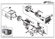
Fig. 3 Air fi ltering<br />
d Gasket<br />
e Gasket<br />
f Filter cartridge<br />
g Screw button<br />
h Filter cover<br />
7.2.2 Lubricatio<br />
Fig. 4 Lubrication<br />
H Oil fi lling point<br />
I Oil sight glass<br />
M<br />
K I<br />
K Oil discharge point<br />
M Oil recommendation plate<br />
f d e h g<br />
NOTICE<br />
20 | www.gd-elmorietschle.com © Gardner Denver Schopfheim GmbH, Gardner Denver Deutschland GmbH<br />
Insuffi cient maintenance on the air fi lter<br />
The power of the machine lessens and damage may<br />
occur to the machine.<br />
The fi lter cartridge Fig. 3/f) must be cleaned by<br />
purging or replaced more or less often depending on<br />
how dirty the discharged medium is.<br />
Undo the screw buttonFig. 3/g). Remove the fi lter<br />
cover (Fig. 3/h) and gaskets Fig. 3/d/e). Remove the<br />
fi lter cartridgeFig. 3/f) and clean or replace.<br />
Re-assemble in reverse order.<br />
NOTICE<br />
Always change the oil when the machine is at<br />
operating temperature and in an atmospherically<br />
ventilated area.<br />
If it is not completely emptied the amount that can<br />
be refi lled is reduced..<br />
The waste oil must be disposed of in compliance with<br />
the local environmental protection regulations.<br />
If you are going to use another oil type, empty the<br />
oil removing device housing and oil cooler completely..<br />
The oil level must be checked at least once a day,<br />
if necessary top the oil up to the upper edge of the<br />
sight glass (Fig. 4/I) First oil change after 500 hours<br />
of operation. Subsequent oil changes after 500-<br />
2000 hours of operation. Reduce the change intervals<br />
accordingly depending on how contaminated<br />
the discharged medium is..
7.2.3 Oil removal<br />
g<br />
h<br />
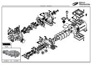
Fig. 5 Oil removal<br />
L Oil separator element<br />
L1 O ring<br />
T Oil reservoir cover<br />
g Screw button<br />
h Filter cover<br />
T L L 1<br />
Maintenance and repair<br />
Only lubricating oils complying with DIN 51506<br />
group VC/VCL or a synthetic oil approved by <strong>Elmo</strong><br />
<strong>Rietschle</strong> must be used. The viscosity of the oil must<br />
comply with ISO-VG46 as per DIN51519.<strong>Elmo</strong> <strong>Rietschle</strong><br />
oil types: MULTI-LUBE 46 (mineral oil) and<br />
SUPER-LUBE46 (synthetic oil) see also oil recommendation<br />
plate (Fig. 4/M)).<br />
If the oil is subject to high temperatures (ambient or<br />
intake temperatures over 30°C, insuffi cient cooling,<br />
60 Hz operation etc.) the oil change interval may be<br />
extended by using the recommended synthetic oil..<br />
WARNING<br />
Heavily contaminated air oil removing devices lead<br />
to increased pump temperatures and in extreme<br />
cases may cause the lubricating oil to ignite spontaneously<br />
The oil separator element may be contaminated with<br />
particles of dirt when it has been running for a long<br />
time (power consumption and pump temperature<br />
increase). We therefore recommend replacing the<br />
device every 3,000 operating hours (Fig. 5/L) as it is<br />
not possible to clean it.<br />
Reduce the change intervals accordingly depending<br />
on how contaminated the discharged medium is.<br />
Changing: Undo the screw button (Fig. 5/g). Remove<br />
the fi lter cover (Fig. 5/h). Unscrew the oil reservoir<br />
cover (Fig. 5/T). Replace the oil separator element<br />
Fig. 5/L). Re-use the O ring (Fig. 5/L 1).<br />
Re-assemble in reverse order<br />
www.gd-elmorietschle.com © Gardner Denver Schopfheim GmbH, Gardner Denver Deutschland GmbH |<br />
21
Maintenance and repair<br />
7.3 Repair/ Service<br />
Fig. 6 Clearance certifi cate 7.7025.003.17<br />
22 | www.gd-elmorietschle.com © Gardner Denver Schopfheim GmbH, Gardner Denver Deutschland GmbH<br />
a) For on site repair work the motor must be<br />
disconnected from the mains by a qualifi ed<br />
electrician so that it cannot be started up again<br />
accidentally. For repairs use the manufacturer,<br />
its branch offi ces or authorised dealers. Please<br />
contact the manufacturer for the address of the<br />
service centre responsible for you (see Manufacturer’s<br />
address)<br />
NOTICE<br />
For each machine that is sent to an <strong>Elmo</strong> <strong>Rietschle</strong><br />
Service centre for inspection, maintenance<br />
or repair, a fully completed, signed declaration of<br />
harmlessness must be enclosed.<br />
The declaration of harmlessness is part of the<br />
supplier‘s documentation.<br />
b) After a repair or re-commissioning, the actions<br />
listed under “Installation” and “Commissioning”<br />
must be carried out as for initial commissioning.
7.4 Spare parts<br />
Fig. 7 Spare parts list (example))<br />
Fig. 8 Web site http://www.service-er.de<br />
Maintenance and repair<br />
Order spare parts in accordance with the:<br />
• Spare parts list:<br />
E 146 ➝ V-<strong>VGA</strong> / V-<strong>VGC</strong><br />
• Download the PDF fi le<br />
ht tp://www.gd-elmorietschle.com<br />
➝ Downloads<br />
➝ Product Documents<br />
➝ V Series ➝Spare Parts<br />
• Parts subject to wear and gaskets are indicated<br />
separately on the list.<br />
• Web site:<br />
http://www.service-er.de<br />
• Select the type, size and design.<br />
NOTICE<br />
Only use original spare parts or parts approved by<br />
the manufacturer. The use of other parts may lead to<br />
malfunctions and invalidate liability or the guarantee<br />
for any consequences arising.<br />
www.gd-elmorietschle.com © Gardner Denver Schopfheim GmbH, Gardner Denver Deutschland GmbH |<br />
23
Malfunctions: Causes and elimination<br />
8 Malfunctions: Causes and elimination<br />
Fault Cause Troubleshooting Important<br />
Machine is switched<br />
off by the motor protection<br />
switch<br />
Pumping capacity is<br />
insuffi cient<br />
Mains voltage/ Frequency<br />
does not correspond with the<br />
motor data<br />
Connection to motor terminal<br />
board is not correct<br />
Motor protection switch is not<br />
set correctly<br />
Motor protection switch is<br />
triggered too quickly<br />
Vacuum pump or its oil is too<br />
cold<br />
The lubricating oil is too viscous<br />
The oil separator element is<br />
dirty.<br />
The back pressure is too high<br />
when the exhaust air is being<br />
discharged.<br />
The suction pipe is too long or<br />
too narrow<br />
Leak on the suction side of<br />
the vacuum pump or in the<br />
system<br />
24 | www.gd-elmorietschle.com © Gardner Denver Schopfheim GmbH, Gardner Denver Deutschland GmbH<br />
Check by qualifi ed electrician Section 5.5<br />
Use a motor protection switch<br />
with an overload-dependent<br />
delayed switch off that takes<br />
into consideration the short<br />
term excess current at start<br />
up (version with short circuit<br />
and overload trigger as per<br />
VDE 0660 Part 2 orIEC 947-4)<br />
Note the ambient temperature<br />
and the intake temperature<br />
The oil viscosity must comply<br />
with ISO VG 46 as per DIN<br />
51519<br />
Change the oil separator element<br />
Section 2.3<br />
Section 7.2.2<br />
Section 7.2.3<br />
Check the hose or the pipe Section 5.3<br />
Check the hose or the pipe Section 5.3<br />
Check the pipework and<br />
screw connections for leaks<br />
and to ensure that they are<br />
fi rmly seated.<br />
The intake fi lter is dirty Clean or replace the intake<br />
fi lter<br />
Section 7.2<br />
Section 7.2.1
Malfunctions: Causes and elimination<br />
Fault Cause Troubleshooting Important<br />
Final pressure (max.<br />
vacuum) is not<br />
reached<br />
Leak on the suction side of<br />
the vacuum pump or in the<br />
system<br />
Check the pipework and<br />
screw connections for leaks<br />
and to ensure that they are<br />
fi rmly seated.<br />
Incorrect oil viscosity The oil viscosity must comply<br />
with ISO VG 46 as per DIN<br />
51519<br />
Machine gets too hot Ambient or intake temperature<br />
is too high<br />
Exhaust air contains<br />
visible oil mist<br />
Cooling air supply is obstructed<br />
The lubricating oil is too viscous<br />
The oil separator element is<br />
dirty.<br />
The back pressure is too high<br />
when the exhaust air is being<br />
discharged.<br />
The oil separator element is<br />
not inserted correctly or the O<br />
ring is missing<br />
Ensure it is being used properly<br />
Check environmental conditions<br />
Section 7.2<br />
Section 7.2.2<br />
Section 2.3<br />
Section 5.1<br />
Clean ventilation slots Section 7.2<br />
The oil viscosity must comply<br />
with ISO VG 46 as per DIN<br />
51519<br />
Change the oil separator element<br />
Section 7.2.2<br />
Section 7.2.3<br />
Check the hose or the pipe Section 5.3<br />
Check that it is correctly<br />
seated<br />
Section 7.2.3<br />
Unsuitable oil is being used Use suitable types Section 7.2.2<br />
The oil separator element is<br />
dirty.<br />
The back pressure is too high<br />
when the exhaust air is being<br />
discharged.<br />
Ambient or intake temperature<br />
is too high<br />
Cooling air supply is obstructed<br />
Change the oil separator element<br />
Section 7.2.3<br />
Check the hose or the pipe Section 5.3<br />
Ensure it is being used properly<br />
Check environmental conditions<br />
Section 2.3<br />
Section 5.1<br />
Clean ventilation slots Section 7.2<br />
www.gd-elmorietschle.com © Gardner Denver Schopfheim GmbH, Gardner Denver Deutschland GmbH |<br />
25
Malfunctions: Causes and elimination<br />
Fault Cause Troubleshooting Important<br />
The vacuum pump<br />
produces a abnormal<br />
noise<br />
(The blades making<br />
a hammering noise<br />
when starting from<br />
cold is normal if it<br />
disappears within<br />
two minutes as the<br />
operating temperature<br />
increases)<br />
Water in lubricating<br />
oil<br />
The pump housing is worn<br />
(chatter marks)<br />
26 | www.gd-elmorietschle.com © Gardner Denver Schopfheim GmbH, Gardner Denver Deutschland GmbH<br />
Repair by manufacturer or<br />
authorised workshop<br />
Blades are damaged Repair by manufacturer or<br />
authorised workshop<br />
Vacuum pump or its oil is too<br />
cold<br />
The lubricating oil is too viscous<br />
Note the ambient temperature<br />
and the intake temperature<br />
The oil viscosity must comply<br />
with ISO VG 46 as per DIN<br />
51519<br />
Pump sucks in water Install water interceptor upstream<br />
of the pump<br />
The pump sucks in more water<br />
vapour than is suitable for<br />
its water vapour compatibility<br />
Pump only works for a short<br />
time and therefore does not<br />
reach its normal operating<br />
temperature<br />
<strong>Elmo</strong> <strong>Rietschle</strong><br />
Service<br />
<strong>Elmo</strong> <strong>Rietschle</strong><br />
Service<br />
Section 2.3<br />
Section 7.2.2<br />
—<br />
Contact the manufacturer for<br />
increased gas ballast —<br />
Let the pump continue to run<br />
with a closed suction side<br />
after extracting the water<br />
vapour until the water has<br />
evaporated from the oil<br />
Please contact <strong>Elmo</strong> <strong>Rietschle</strong> Service for other malfunctions or those that cannot be eliminated.<br />
—
9 Technical Data<br />
V-<strong>VGA</strong> / V-<strong>VGC</strong> 25 40<br />
Sound pressure level (max.)<br />
EN ISO 3744<br />
Tolerance± 3 dB(A)<br />
Abb. Fig. 9 9 Data Datenblatt sheet (example) (Beispiel)<br />
dB(A)<br />
Weight (max.) kg<br />
50 Hz 62 65<br />
60 Hz 63 67<br />
3~ 40 50<br />
1~ 45 53<br />
Length mm 461 508<br />
Width mm 329 381<br />
Height mm 270 270<br />
Vacuum connection G 3 / 8 G 3 / 8<br />
Correct amount of oil l 1,0 2,0<br />
Technical Data<br />
You will fi nd more technical data on data sheets<br />
D 146/1 and D 147/1<br />
• Download the PDF fi le:<br />
D 146/1 ➝ V-<strong>VGA</strong> 4 / V-<strong>VGA</strong> 6<br />
D 147/1 ➝ V-<strong>VGC</strong> 4 / V-<strong>VGC</strong> 6<br />
• Download the PDF fi le:<br />
http://www.gd-elmorietschle.com<br />
➝ Downloads<br />
➝ Product Documents<br />
➝ V Series ➝Data sheets<br />
NOTICE<br />
Subject to technical changes!<br />
www.gd-elmorietschle.com © Gardner Denver Schopfheim GmbH, Gardner Denver Deutschland GmbH |<br />
27
<strong>Elmo</strong> <strong>Rietschle</strong> is a brand of<br />
Gardner Denver‘s Industrial Products<br />
Division and part of Blower Operations.<br />
www.gd-elmorietschle.com<br />
er.de@gardnerdenver.com<br />
Gardner Denver<br />
Schopfheim GmbH<br />
Roggenbachstraße 58<br />
79650 Schopfheim · Deutschland<br />
Tel. +49 7622 392-0<br />
Fax +49 7622 392-300
Hereby the manufacturer<br />
confirms:<br />
that the machine:<br />
of the:<br />
EC - declaration of conformity 2006/42/EC<br />
Gardner Denver Schopfheim GmbH<br />
Postfach 1260<br />
D-79642 Schopfheim<br />
Oil lubricated vacuum pump<br />
Series: V-<strong>VGA</strong> / V-<strong>VGC</strong><br />
Type: V-<strong>VGA</strong> 4, V-<strong>VGA</strong> 6, V-<strong>VGA</strong> 10,<br />
V-<strong>VGA</strong> 15, V-<strong>VGA</strong> 20<br />
V-<strong>VGC</strong> 4, V-<strong>VGC</strong> 6, V-<strong>VGC</strong> 10,<br />
V-<strong>VGC</strong> 15<br />
is conform to the regulations of the guideline indicated above.<br />
The following harmonized and national standards and specifications are applied:<br />
EN 1012-1:2010<br />
Compressors and vacuum pumps — Safety requirements — Part 1:<br />
Compressors<br />
EN 1012-2:1996+A1:2009 Compressors and vacuum pumps — Safety requirements — Part 2:<br />
Vacuum pumps<br />
These declarations of conformity are invalid when the machine has been modified without prior approval<br />
by us and the approval has been documented in writing.<br />
Name and address of the EC person in<br />
charge for documentation<br />
Gardner Denver Schopfheim GmbH<br />
Schopfheim, 1.8.2011<br />
Dr. Friedrich Justen, Director Engineering<br />
Gardner Denver Schopfheim GmbH<br />
Postfach 1260<br />
D-79642 Schopfheim<br />
C_0036_EN
Safety declaration form<br />
for vacuum pumps and components<br />
Page 1 of 1<br />
Gardner Denver Schopfheim GmbH<br />
Roggenbachstr. 58, 79650 Schopfheim Phone: +49/(0)7622/392-0 Fax: +49/(0)7622/392-300<br />
Repairs and/or maintenance of vacuum pumps and components will only be carried out if a declaration has been<br />
filled in correctly and completely.<br />
If not, the repair work cannot be started and delays will result.<br />
This declaration must only be filled in and signed by authorised qualified staff.<br />
1. Type of vacuum pumps/ components<br />
Type description:<br />
Machine number<br />
Order number:<br />
Delivery date:<br />
3. Condition of vacuum pumps/ components 4. Contamination of the vacuum pumps/<br />
Was this being operated? YES � NO � components when in use<br />
Which lubrication was used? Toxic YES � NO �<br />
Corrosive YES � NO �<br />
Was the pump/ component emptied? Microbiological*) YES � NO �<br />
(Product/Consumables) YES � NO � Explosive*) YES � NO �<br />
Has the pump/ component been cleaned and decontaminaRadioactive*) YES � NO �<br />
other YES � NO �<br />
YES �<br />
Cleaning agent:<br />
Cleaning method:<br />
*) Microbiological, explosive or radioactively contaminated vacuum pumps/ components will only be accepted<br />
with proof that they have been cleaned properly.<br />
Type of toxic substance or process-related, dangerous reaction products with which the vacuum pumps/<br />
components came into contact:<br />
Trade name, manufacturer's Chemical Hazard Action to be taken if toxic First aid in the event of<br />
product name<br />
1<br />
2<br />
3<br />
4<br />
Personal protection measures:<br />
name class substances are released accidents<br />
Hazardous decomposition products when subjected to thermal load YES � NO �<br />
Which?<br />
5. Legally binding declaration<br />
We swear that the information in this declaration is accurate and complete and that I, the undersigned, am in a<br />
position to judge this. We are aware that we are liable to the contractor for damage caused by incomplete and<br />
inaccurate information. We undertake to release the contractor from any damage claims from third parties arising<br />
from incomplete or incorrect information. We are aware that, regardless of this declaration, we are directly liable<br />
to third parties including in particular the contractor's staff entrusted with handling or repairing the product.<br />
Company:<br />
Street: Post code/ Town:<br />
Phone: Fax:<br />
Name (in capitals) Position:<br />
2. Reason for the submission<br />
Date: Company stamp:<br />
Legally binding signature:<br />
7.7025.003.17<br />
TOS no. / Index: 7.7025.003.17 / 03 Office responsible: GS File management: ..\7702500317.xl<br />
Gardner Denver Schopfheim GmbH Postfach 1260 D-79642 Schopfheim