TDP 0,2 • TDPZ 0,2 - Baumer Hübner
TDP 0,2 • TDPZ 0,2 - Baumer Hübner
TDP 0,2 • TDPZ 0,2 - Baumer Hübner

Create successful ePaper yourself
Turn your PDF publications into a flip-book with our unique Google optimized e-Paper software.
MB079 tdp-z02_mb (12A1)<br />
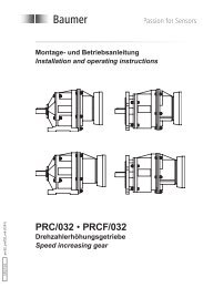
Montage- und Betriebsanleitung<br />
Installation and operating instructions<br />
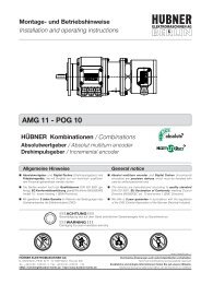
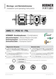
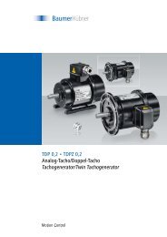
<strong>TDP</strong> 0,2 <strong>•</strong> <strong>TDP</strong>Z 0,2<br />
Tachogenerator/Doppel-Tachogenerator<br />
Ausführungen mit EURO-Flansch<br />
Tachogenerator/Twin Tachogenerator<br />
Versions with EURO flange
Inhaltsverzeichnis<br />
Inhaltsverzeichnis<br />
1 Allgemeine Hinweise ...................................................................................................................................................1<br />
2 Sicherheitshinweise .....................................................................................................................................................3<br />
3 Vorbereitung ......................................................................................................................................................................5<br />
3.1 Lieferumfang Ausführung LT - B10 ...........................................................................................................5<br />
3.2 Lieferumfang Ausführung LT - B10/B14 (mit zweitem Wellenende) ........................................6<br />
3.3 Lieferumfang Ausführung LS - B10 ..........................................................................................................7<br />
3.4 zur Montage erforderlich (nicht im Lieferumfang enthalten) .......................................................7<br />
3.5 Erforderliches Werkzeug (nicht im Lieferumfang enthalten) .......................................................8<br />
4 Montage ................................................................................................................................................................................8<br />
4.1 Schritt 1 ...................................................................................................................................................................8<br />
4.2 Schritt 2 ...................................................................................................................................................................9<br />
4.3 Schritt 3 ................................................................................................................................................................ 10<br />
4.4 Schritt 4 ................................................................................................................................................................ 10<br />
4.5 Max. zulässige Anbaufehler unter Verwendung<br />
der <strong>Baumer</strong> <strong>Hübner</strong> Federscheiben-Kupplung K 35 .....................................................................11<br />
4.6 Schritt 5 -<br />
Ausführung <strong>TDP</strong> (<strong>TDP</strong>Z) 0,2 LT mit Klemmenkasten und Druckschraube M16x1,5 .. 12<br />
4.7 Schritt 5 -<br />
Ausführung <strong>TDP</strong> 0,2 LT mit Klemmenkasten und Kabelverschraubung M20x1,5 ....... 12<br />
4.8 Schritt 5 - Ausführung <strong>TDP</strong> 0,2 LS mit Kabelverschraubung M16x1,5 .............................. 13<br />
4.9 Anbauhinweis .................................................................................................................................................... 14<br />
5 Abmessungen ............................................................................................................................................................... 15<br />
5.1 Ausführungen <strong>TDP</strong> 0,2 LT - B10 ............................................................................................................. 15<br />
5.2 Ausführungen <strong>TDP</strong>Z 0,2 LT - B10 .......................................................................................................... 15<br />
5.3 Ausführungen <strong>TDP</strong> 0,2 LT - B10/B14 ................................................................................................... 16<br />
5.4 Ausführung <strong>TDP</strong>Z 0,2 LT - B10/B14 ...................................................................................................... 16<br />
5.5 Ausführung <strong>TDP</strong> 0,2 LS - B10 .................................................................................................................. 16<br />
6 Elektrischer Anschluss ...........................................................................................................................................17<br />
6.1 Ausführung <strong>TDP</strong> 0,2 LT ................................................................................................................................17<br />
6.2 Ausführung <strong>TDP</strong>Z 0,2 LT .............................................................................................................................17<br />
6.3 Ausführung <strong>TDP</strong> 0,2 LS ...............................................................................................................................17<br />
7 Betrieb und Wartung ................................................................................................................................................ 18<br />
7.1 Austausch der Kohlebürsten ..................................................................................................................... 18<br />
8 Demontage ...................................................................................................................................................................... 19<br />
8.1 Schritt 1 -<br />
Ausführung <strong>TDP</strong> 0,2 LT mit Klemmenkasten und Druckschraube M16x1,5 .................... 19<br />
8.2 Schritt 1 -<br />
Ausführung <strong>TDP</strong> 0,2 LT mit Klemmenkasten und Kabelverschraubung M20x1,5 ....... 19<br />
8.3 Schritt 1 - Ausführung <strong>TDP</strong> 0,2 LS mit Kabelverschraubung M16x1,5 .............................. 20<br />
8.4 Schritt 2 ................................................................................................................................................................ 21<br />
8.5 Schritt 3 ................................................................................................................................................................ 21<br />
8.6 Schritt 4 ................................................................................................................................................................22<br />
9 Technische Daten .......................................................................................................................................................23<br />
9.1 Allgemeine Daten ...........................................................................................................................................23<br />
9.2 Daten nach Typ ................................................................................................................................................ 24<br />
10 Anhang: EU-Konformitätserklärung .............................................................................................................. 27<br />
11 Zubehör ..............................................................................................................................................................................29<br />
tdp-z02_mb (12A1) MB079
Table of contents<br />
MB079<br />
tdp-z02_mb (12A1)<br />
Table of contents<br />
1 General notes ...................................................................................................................................................................2<br />
2 Security indications .....................................................................................................................................................4<br />
3 Preparation .........................................................................................................................................................................5<br />
3.1 Scope of delivery version LT - B10 ...........................................................................................................5<br />
3.2 Scope of delivery version LT - B10/B14 (with rear extension shaft) ........................................6<br />
3.3 Scope of delivery version LS - B10 ..........................................................................................................7<br />
3.4 required for mounting (not included in scope of delivery) ............................................................7<br />
3.5 required tools (not included in scope of delivery) .............................................................................8<br />
4 Mounting ..............................................................................................................................................................................8<br />
4.1 Step 1 .......................................................................................................................................................................8<br />
4.2 Step 2 .......................................................................................................................................................................9<br />
4.3 Step 3 .................................................................................................................................................................... 10<br />
4.4 Step 4 .................................................................................................................................................................... 10<br />
4.5 Max. permissible mounting tolerance<br />
when the <strong>Baumer</strong> <strong>Hübner</strong> K 35 spring disk coupling is used ...................................................11<br />
4.6 Step 5 -<br />
Version <strong>TDP</strong> (<strong>TDP</strong>Z) 0,2 LT with terminal box and pressure screw M16x1,5 ................. 12<br />
4.7 Step 5 -<br />
Version <strong>TDP</strong> 0,2 LT with terminal box and cable gland M20x1,5 .......................................... 12<br />
4.8 Step 5 - Version <strong>TDP</strong> 0,2 LS with cable gland M16x1,5 ............................................................. 13<br />
4.9 Mounting instruction ...................................................................................................................................... 14<br />
5 Dimensions ..................................................................................................................................................................... 15<br />
5.1 Versions <strong>TDP</strong> 0,2 LT - B10 ........................................................................................................................ 15<br />
5.2 Versions <strong>TDP</strong>Z 0,2 LT - B10 ..................................................................................................................... 15<br />
5.3 Versions <strong>TDP</strong> 0,2 LT - B10/B14 ............................................................................................................... 16<br />
5.4 Version <strong>TDP</strong>Z 0,2 LT - B10/B14 .............................................................................................................. 16<br />
5.5 Version <strong>TDP</strong> 0,2 LS - B10 .......................................................................................................................... 16<br />
6 Electrical connection ................................................................................................................................................ 17<br />
6.1 Version <strong>TDP</strong> 0,2 LT ....................................................................................................................................... 17<br />
6.2 Version <strong>TDP</strong>Z 0,2 LT ..................................................................................................................................... 17<br />
6.3 Version <strong>TDP</strong> 0,2 LS ....................................................................................................................................... 17<br />
7 Operation and maintenance ................................................................................................................................. 18<br />
7.1 Replace of the carbon brushes ............................................................................................................... 18<br />
8 Dismounting ................................................................................................................................................................... 19<br />
8.1 Step 1 -<br />
Version <strong>TDP</strong> 0,2 LT with terminal box and pressure screw M16x1,5 .................................. 19<br />
8.2 Step 1 -<br />
Version <strong>TDP</strong> 0,2 LT with terminal box and cable gland M20x1,5 .......................................... 19<br />
8.3 Step 1 - Version <strong>TDP</strong> 0,2 LS with cable gland M16x1,5 ............................................................. 20<br />
8.4 Step 2 .................................................................................................................................................................... 21<br />
8.5 Step 3 .................................................................................................................................................................... 21<br />
8.6 Step 4 .................................................................................................................................................................... 22<br />
9 Technical data ............................................................................................................................................................... 25<br />
9.1 General data ...................................................................................................................................................... 25<br />
9.2 Type data ............................................................................................................................................................. 26<br />
10 Appendix: EU Declaration of conformity .................................................................................................... 28<br />
11 Accessories .................................................................................................................................................................... 29
1 Allgemeine Hinweise<br />
1 Allgemeine Hinweise<br />
1.1 Zeichenerklärung:<br />
�1<br />
�<br />
i Information<br />
Gefahr<br />
Warnung bei möglichen Gefahren<br />
Hinweis zur Beachtung<br />
Hinweis zur Gewährleistung eines einwandfreien Betriebes des Produkts<br />
Empfehlung für die Produkthandhabung<br />
1.2 Der Tachogenerator <strong>TDP</strong> 0,2 / Doppel-Tacho <strong>TDP</strong>Z 0,2 ist ein generatorisch arbeitendes<br />
Prä zi sions-Drehzahlmessgerät, das mit Sorgfalt nur von technisch qualifiziertem Per sonal<br />
gehandhabt werden darf.<br />
1.3 Der LongLife Tachogenerator ist wartungsfrei. Die zu erwartende Lebensdauer des Gerätes<br />
hängt von den Kugellagern ab, die mit einer Dauerschmierung ausgestattet sind.<br />
1.4 Der Lagertemperaturbereich des Gerätes liegt zwischen -15°C bis +70°C,<br />
1.5 Der Betriebstemperaturbereich des Gerätes liegt zwischen -30°C bis +130°C,<br />
am Gehäuse gemessen.<br />
1.6 EU-Konformitätserklärung gemäß den europäischen Richtlinien.<br />
1.7 Wir gewähren 2 Jahre Gewährleistung im Rahmen der Bedingungen des Zentralverbandes der<br />
Elektroindustrie (ZVEI).<br />
1.8 Der Tachogenerator darf nur wie in dieser Anleitung beschrieben geöffnet werden. Reparaturen<br />
oder Wartungsarbeiten, die ein vollständiges Öffnen des Tachogenerators erfordern, sind vom<br />
Hersteller durchzuführen.<br />
1.9 Bei Rückfragen bzw. Nachlieferungen sind die auf dem Typenschild des Gerätes angegebenen<br />
Daten, insbesondere Typ und Seriennummer, unbedingt anzugeben.<br />
1.10 Alle Bestandteile des Tachos sind nach länderspezifischen Vorschriften zu entsorgen.<br />
i<br />
Achtung!<br />
Beschädigung des auf dem Gerät befindlichen Siegels führt zu Gewährleistungsverlust.<br />
tdp-z02_mb (12A1) MB079
1 General notes<br />
1.1 Symbol guide:<br />
�<br />
i Information<br />
Danger<br />
Warnings of possible danger<br />
General information for attention<br />
Informations to ensure correct product operation<br />
Recommendation for product handling<br />
Warning!<br />
Damaging the seal on the device invalidates warranty.<br />
General notes 1<br />
1.2 The tachogenerator <strong>TDP</strong> 0,2 / twin tachogenerator <strong>TDP</strong>Z 0,2 is a precision rotary<br />
measurement device which must be handled with care by skilled personnel only.<br />
1.3 The LongLife tachogenerator is maintenance-free. The expected operating life of the device<br />
depends on the ball bearings, which are equipped with a permanent lubrication.<br />
1.4 The storage temperature range of the device is between -15°C and +70°C.<br />
1.5 The operating temperature range of the device is between -30°C and +130°C,<br />
measured at the housing.<br />
1.6 EU-Declaration of Conformity meeting to the European Council Directives.<br />
1.7 We offer a 2-year warranty in accordance with the regulations of the ZVEI (Central Association of<br />
the German Electrical Industry).<br />
1.8 The tachogenerator may be only opened as described in this instruction. Repair or maintenance<br />
work that requires opening the tachogenerator completely must be carried out by the<br />
manufacturer.<br />
1.9 In the event of queries or subsequent deliveries, the data on the device type label must be<br />
quoted, especially the type designation and the serial number.<br />
1.10 Tacho components are to be disposed of according to the regulations prevailing in the respective<br />
country.<br />
i<br />
MB079 tdp-z02_mb (12A1) �2
2 Sicherheitshinweise<br />
2 Sicherheitshinweise<br />
2.1 Verletzungsgefahr durch rotierende Wellen<br />
�3<br />
Haare und Kleidungsstücke können von rotierenden Wellen erfasst werden.<br />
<strong>•</strong> Vor allen Arbeiten alle Betriebsspannungen ausschalten und Maschinen stillsetzen.<br />
2.2 Zerstörungsgefahr durch mechanische Überlastung<br />
Eine starre Befestigung kann zu Überlastung durch Zwangskräfte führen.<br />
<strong>•</strong> Die Beweglichkeit des Tachogenerators niemals einschränken. Unbedingt die Montagehinweise<br />
beachten.<br />
<strong>•</strong> Die vorgegebenen Abstände und/oder Winkel unbedingt einhalten.<br />
2.3 Zerstörungsgefahr durch mechanischen Schock<br />
Starke Erschütterungen, z. B. Hammerschläge, können zur Zerstörung des Gerätes führen.<br />
<strong>•</strong> Niemals Gewalt anwenden. Bei sachgemäßer Montage lässt sich alles leichtgängig zusammenfügen.<br />
<strong>•</strong> Für die Demontage geeignetes Abziehwerkzeug benutzen.<br />
2.4 Zerstörungsgefahr durch Verschmutzung<br />
Schmutz kann im Tachogenerator zu dessen Beschädigung führen.<br />
<strong>•</strong> Während aller Arbeiten am geöffneten Klemmenkasten und beim Austausch der Kohlebürsten<br />
auf absolute Sauberkeit achten.<br />
<strong>•</strong> Bei der Demontage niemals Öl oder Fett in das Innere des Tachogenerators gelangen lassen.<br />
2.5 Zerstörungsgefahr durch klebende Flüssigkeiten<br />
Klebende Flüssigkeiten können die Magnete und Kohlebürsten beschädigen. Die Demontage<br />
eines mit der Achse verklebten Tachogenerators kann zu dessen Zerstörung führen.<br />
2.6 Explosionsgefahr<br />
Den Tachogenerator nicht in Bereichen mit explosionsgefährdeten bzw. leicht entzündlichen<br />
Materialien verwenden.<br />
Durch eventuelle Funkenbildung können diese leicht Feuer fangen und/oder explodieren.<br />
tdp-z02_mb (12A1) MB079
2 Security indications<br />
2.1 Risk of injury due to rotating shafts<br />
Hair and clothes may become tangled in rotating shafts.<br />
Security indications 2<br />
<strong>•</strong> Before all work switch off all operating voltages and ensure machinery is stationary.<br />
2.2 Risk of destruction due to mechanical overload<br />
Rigid mounting may give rise to constraining forces.<br />
<strong>•</strong> Never restrict the freedom of movement of the tachogenerator. The installation instructions<br />
must be followed.<br />
<strong>•</strong> It is essential that the specified clearances and/or angles are observed.<br />
2.3 Risk of destruction due to mechanical shock<br />
Violent shocks, e. g. due to hammer impacts, can lead to the destruction of the device.<br />
<strong>•</strong> Never use force. Assembly is simple when correct procedure is followed.<br />
<strong>•</strong> Use suitable puller for disassembly.<br />
2.4 Risk of destruction due to contamination<br />
Dirt penetrating inside the tachogenerator can damage the tachogenerator.<br />
<strong>•</strong> Absolute cleanliness must be maintained when carrying out any work on the open terminal box<br />
and while changing the carbon brushes.<br />
<strong>•</strong> When dismantling, never allow lubricants to penetrate the tachogenerator.<br />
2.5 Risk of destruction due to adhesive fluids<br />
Adhesive fluids can damage the magnets and the carbon brushes. Dismounting an tacho, secured<br />
to a shaft by adhesive may lead to the destruction of the unit.<br />
2.6 Explosion risk<br />
Do not use the tachogenerator in areas with explosive and/or highly inflammable materials.<br />
They may explode and/or catch fire by possible spark formation.<br />
MB079 tdp-z02_mb (12A1) �4
3 Vorbereitung / Preparation<br />
3 Vorbereitung<br />
3.1 Lieferumfang Ausführung LT - B10<br />
3<br />
�5<br />
1 Gehäuse<br />
2 EURO-Flansch<br />
3 Welle mit Passfeder<br />
4 Kohlebürstenhalterung mit Kohlebürsten<br />
4.1<br />
2<br />
Kohlebürsten (auch als Zubehör erhältlich,<br />
Bestellnummer 11076778 (S 7 / H 7))<br />
5 Abdeckhaube<br />
6 Torx-Schraube M4x12 mm<br />
7 Abdeckung für Kohlebürsten<br />
1)<br />
8 Torx-Schraube M4x6 mm<br />
1)<br />
9 zweite Kohlebürstenhalterung<br />
mit Kohlebürsten<br />
10 Anschlussklemmen, siehe Abschnitt 6.1 und 6.2<br />
11 Klemmenkastendeckel<br />
1<br />
12 Kombi-Torx-Schraube M4x32 mm<br />
13 Druckschraube M16x1,5 für Kabel ø6-8 mm<br />
14 Kabelverschraubung M20x1,5 für Kabel ø5-13 mm<br />
1) nur Ausführung <strong>TDP</strong>Z<br />
10<br />
11<br />
12<br />
4<br />
13<br />
3 Preparation<br />
3.1 Scope of delivery version LT - B10<br />
1 Housing<br />
2 EURO flange<br />
3 Shaft with key<br />
4 Holder for carbon brushes with carbon brushes<br />
4.1<br />
6<br />
5<br />
14<br />
Carbon brushes (also available as accessory,<br />
order number 11076778 (S 7 / H 7))<br />
5 Cover<br />
8<br />
7<br />
6 Screw with torx drive M4x12 mm<br />
7 Cover for carbon brushes<br />
1)<br />
8 Screw with torx drive M4x6 mm<br />
1)<br />
9 Second holder for carbon brushes<br />
with carbon brushes<br />
10 Connecting terminal, see section 6.1 and 6.2<br />
11 Terminal box cover<br />
1)<br />
1)<br />
12 Screw with torx and slotted drive M4x32 mm<br />
13 Pressure screw M16x1,5 for cable ø6-8 mm<br />
14 Cable gland M20x1,5 for cable ø5-13 mm<br />
1) Only version <strong>TDP</strong>Z<br />
4.1<br />
9<br />
1) 1) 1)<br />
8<br />
7<br />
tdp-z02_mb (12A1) MB079
3.2 Lieferumfang Ausführung LT - B10/B14<br />
(mit zweitem Wellenende)<br />
1 Gehäuse<br />
2 EURO-Flansch<br />
3 Welle mit Passfeder<br />
4 Kohlebürstenhalterung mit Kohlebürsten<br />
4.1<br />
3<br />
2<br />
Kohlebürsten (auch als Zubehör erhältlich,<br />
Bestellnummer 11076778 (S 7 / H 7))<br />
7 Abdeckung für Kohlebürsten<br />
1)<br />
8 Torx-Schraube M4x6 mm<br />
1)<br />
9 zweite Kohlebürstenhalterung<br />
mit Kohlebürsten<br />
10 Anschlussklemmen (siehe Abschnitt 6.1 und 6.2)<br />
11 Klemmenkastendeckel<br />
12 Kombi-Torx-Schraube M4x32 mm<br />
13 Druckschraube M16x1,5 für Kabel ø6-8 mm<br />
15 Linsenschraube M4x8 mm, ISO 7047<br />
16 Zweites Wellenende ø10 mm, 15,5 mm lang<br />
1) nur Ausführung <strong>TDP</strong>Z<br />
1<br />
10<br />
11<br />
12<br />
13<br />
4<br />
7 15<br />
Vorbereitung / Preparation 3<br />
3.2 Scope of delivery version LT - B10/B14<br />
(with rear extension shaft)<br />
1 Housing<br />
2 EURO flange<br />
3 Shaft with key<br />
4 Holder for carbon brushes with carbon brushes<br />
MB079 tdp-z02_mb (12A1) �6<br />
4.1<br />
16<br />
7<br />
8<br />
Carbon brushes (also available as accessory,<br />
order number 11076778 (S 7 / H 7))<br />
7 Cover for carbon brushes<br />
1)<br />
8 Screw with torx drive M4x6 mm<br />
1)<br />
9 Second holder for carbon brushes<br />
with carbon brushes<br />
10 Connecting terminal (see section 6.1 and 6.2)<br />
11 Terminal box cover<br />
1)<br />
1)<br />
12 Screw with torx and slotted drive M4x32 mm<br />
13 Pressure screw M16x1,5 for cable ø6-8 mm<br />
15 Fillister head screw M4x8 mm, ISO 7047<br />
16 Second shaft end ø10 mm, length 15.5 mm<br />
1) Only version <strong>TDP</strong>Z<br />
9<br />
1)<br />
4.1<br />
7<br />
8<br />
1)<br />
1)
3 Vorbereitung / Preparation<br />
3.3 Lieferumfang Ausführung LS - B10 3.3 Scope of delivery version LS - B10<br />
�7<br />
1 Gehäuse<br />
2 EURO-Flansch<br />
3 Welle mit Passfeder<br />
4 Kohlebürstenhalterung<br />
4.1<br />
1<br />
Kohlebürsten (auch als Zubehör erhältlich,<br />
Bestellnummer 11076778 (S 7 / H 7))<br />
17 Abdeckhaube<br />
18 Torx-Schraube M4x14 mm<br />
2<br />
19 Kabelverschraubung M16x1,5 für Kabel ø5-9 mm<br />
3.4 zur Montage erforderlich<br />
(nicht im Lieferumfang enthalten)<br />
20 Anbauvorrichtung, kundenspezifisch<br />
21 Befestigungsschrauben für Anbauvorrichtung<br />
ISO 4017, M6x16 mm<br />
22 Federscheibenkupplung K 35,<br />
als Zubehör erhältlich, siehe Abschnitt 4.5<br />
23 Anschlusskabel<br />
3<br />
20<br />
12x<br />
21<br />
4<br />
1 Housing<br />
2 EURO flange<br />
3 Shaft with key<br />
4 Holder for carbon brushes<br />
4.1<br />
Carbon brushes (also available as accessory,<br />
order number 11076778 (S 7 / H 7))<br />
17 Cover<br />
17<br />
18 19<br />
18 Screw with torx drive M4x14 mm<br />
19 Cable gland M16x1,5 for cable ø5-9 mm<br />
3.4 required for mounting<br />
(not included in scope of delivery)<br />
22 23<br />
20 Installation fitting, customized<br />
21 Fixing screws for installation fitting ISO 4017,<br />
M6x16 mm<br />
22 Spring disk coupling K 35,<br />
available as accessory, see section 4.5<br />
23 Connecting cable<br />
4.1<br />
tdp-z02_mb (12A1) MB079
3.5 Erforderliches Werkzeug<br />
(nicht im Lieferumfang enthalten)<br />
4 Montage<br />
4.1 Schritt 1<br />
* siehe Seite 7<br />
see page 7<br />
2,5 mm<br />
PH 1*<br />
10, 16, 17 und 22 mm*<br />
TX 20<br />
* je nach Ausführung<br />
24 Werkzeugset als Zubehör erhältlich,<br />
Bestellnummer: 11068265<br />
zul. Anzugsmoment<br />
Max tightening torque<br />
M t = 2-3 Nm<br />
22 *<br />
2.5 mm<br />
Vorbereitung - Montage / Preparation - Mounting 3-4<br />
3.5 required tools<br />
(not included in scope of delivery)<br />
24 Tool kit available as accessory,<br />
order number: 11068265<br />
4 Mounting<br />
4.1 Step 1<br />
2.5 mm<br />
PH 1*<br />
10, 16, 17 and 22 mm*<br />
TX 20<br />
* depending on the version<br />
MB079 tdp-z02_mb (12A1) �8
4 Montage / Mounting<br />
4.2 Schritt 2 4.2 Step 2<br />
* siehe Seite 7<br />
see page 7<br />
�9<br />
Motorwelle einfetten! Lubricate motor shaft!<br />
Die Antriebswelle sollte einen möglichst<br />
kleinen Rundlauffehler aufweisen.<br />
Rundlaufabweichungen verursachen<br />
Vibrationen, die die<br />
Lebensdauer des Tachos verkürzen<br />
können.<br />
21 *<br />
10 mm<br />
20 *<br />
The drive shaft should have as less<br />
runout as possible. Any radial deviation<br />
can cause vibrations, which can<br />
shorten the service life of the tachogenerator.<br />
tdp-z02_mb (12A1) MB079
4.3 Schritt 3 4.3 Step 3<br />
4.4 Schritt 4 4.4 Step 4<br />
* siehe Seite 5, 6 oder 7<br />
see page 5, 6 or 7<br />
2.5 mm<br />
zul. Anzugsmoment<br />
Max tightening torque<br />
M t = 2-3 Nm<br />
20<br />
*<br />
2 21<br />
*<br />
*<br />
22 *<br />
Montage / Mounting 4<br />
10 mm<br />
MB079 tdp-z02_mb (12A1) �10
4 Montage / Mounting<br />
4.5 Max. zulässige Anbaufehler<br />
unter Verwendung der <strong>Baumer</strong> <strong>Hübner</strong><br />
Federscheiben-Kupplung K 35<br />
�11<br />
Tachogeneratoren mit Welle sollten<br />
unter Verwendung der <strong>Baumer</strong> <strong>Hübner</strong><br />
Federscheiben-Kupplung K35 (Zubehör)<br />
angetrieben werden, die sich ohne axialen<br />
Druck auf die Welle schieben lässt.<br />
F max = 10N<br />
±0.2 (±0.05*)<br />
Zulässiger Parallelversatz<br />
Admissible parallel misalignment<br />
* für Ausführung mit isolierender Kunststoffnabe<br />
for insulated hub version<br />
Der Anbau an den Antrieb muss mit<br />
möglichst geringem Winkelfehler<br />
und Parallelversatz erfolgen.<br />
Das harte Aufschlagen von Kupplungsteilen<br />
auf die Welle ist wegen<br />
der Gefahr von Kugellagerbeschädigungen<br />
nicht zulässig.<br />
Zulässiger Winkelfehler<br />
Admissible angular error<br />
4.5 Max. permissible mounting tolerance<br />
when the <strong>Baumer</strong> <strong>Hübner</strong><br />
K 35 spring disk coupling is used<br />
Tachogenerators with a shaft should be<br />
driven through the <strong>Baumer</strong> <strong>Hübner</strong> K35<br />
spring disk coupling (accessory), that can<br />
be pushed onto the shaft without axial<br />
loading.<br />
±1°<br />
±0.7 (±0.3*)<br />
Zulässige Axialbewegung<br />
Admissible axial movement<br />
The tachogenerator must be mounted<br />
on the drive with the least possible angular<br />
error and parallel misalignment.<br />
Coupling components must not be driven<br />
onto the shaft with improper force (e.<br />
g. hammer impacts), because of the risk<br />
of damaging the ball bearings.<br />
All dimensions in millimeters (unless otherwise stated)<br />
tdp-z02_mb (12A1) MB079
4.6 Schritt 5 - Ausführung <strong>TDP</strong> (<strong>TDP</strong>Z) 0,2 LT<br />
mit Klemmenkasten und<br />
Druckschraube M16x1,5<br />
13 *<br />
11<br />
*<br />
12<br />
*<br />
4.7 Schritt 5 - Ausführung <strong>TDP</strong> 0,2 LT<br />
mit Klemmenkasten<br />
und Kabelverschraubung M20x1,5<br />
22 mm<br />
* siehe Seite 5, 6 oder 7<br />
see page 5, 6 or 7<br />
11<br />
*<br />
14<br />
*<br />
16 mm<br />
12<br />
*<br />
Zur Gewährleistung der angegebenen<br />
Schutzart sind nur geeignete<br />
Kabeldurchmesser zu verwenden.<br />
TX 20<br />
Ansicht W bzw. X<br />
siehe Abschnitt 6.1 bzw. 6.2<br />
View W or X<br />
see section 6.1 or 6.2<br />
TX 20<br />
Montage / Mounting 4<br />
4.6 Step 5 - Version <strong>TDP</strong> (<strong>TDP</strong>Z) 0,2 LT<br />
with terminal box<br />
and pressure screw M16x1,5<br />
4.7 Step 5 - Version <strong>TDP</strong> 0,2 LT<br />
with terminal box<br />
and cable gland M20x1,5<br />
Ansicht W bzw. X<br />
siehe Abschnitt 6.1 bzw. 6.2<br />
View W or X<br />
see section 6.1 or 6.2<br />
23 *<br />
ø6-8 mm<br />
23 *<br />
ø5-13 mm<br />
To ensure the specified protection of<br />
the device the correct cable diameter<br />
must be used.<br />
MB079 tdp-z02_mb (12A1) �12
4 Montage / Mounting<br />
4.8 Schritt 5 - Ausführung <strong>TDP</strong> 0,2 LS mit<br />
Kabelverschraubung M16x1,5<br />
* siehe Seite 7<br />
see page 7<br />
�13<br />
Ansicht Y<br />
siehe Abschnitt 6.3<br />
View Y<br />
see section 6.3<br />
Zur Gewährleistung der angegebenen<br />
Schutzart sind nur geeignete<br />
Kabeldurchmesser zu verwenden.<br />
Ansicht Z<br />
siehe Abschnitt 6.3<br />
View Z<br />
see section 6.3<br />
4.8 Step 5 - Version <strong>TDP</strong> 0,2 LS with cable<br />
gland M16x1,5<br />
17<br />
*<br />
18<br />
*<br />
19<br />
*<br />
17 mm<br />
23 *<br />
ø5-9 mm<br />
TX 20<br />
To ensure the specified protection of<br />
the device the correct cable diameter<br />
must be used.<br />
tdp-z02_mb (12A1) MB079
4.9 Anbauhinweis 4.9 Mounting instruction<br />
i i<br />
Wir empfehlen, den Tachogenerator<br />
so zu montieren, dass der Kabelanschluss<br />
keinem direkten Wassereintritt<br />
ausgesetzt ist.<br />
Montage / Mounting 4<br />
We recommend to mount the tachogenerator<br />
in such a manner that the<br />
cable connection is not directly exposed<br />
to water.<br />
MB079 tdp-z02_mb (12A1) �14
5 Abmessungen / Dimensions<br />
5 Abmessungen<br />
5.1 Ausführungen <strong>TDP</strong> 0,2 LT - B10<br />
�15<br />
(61100, 61101, 61102, 61104, 61109,<br />
61110, 61121)<br />
A B<br />
ø7 k6 8.3 3<br />
ø11 k6 12.6 4<br />
ø14 k6 16.1 5<br />
5.2 Ausführungen <strong>TDP</strong>Z 0,2 LT - B10<br />
(61550, 61551, 61552, 61553)<br />
A B<br />
ø7 k6 8.3 3<br />
ø11 k6 12.6 4<br />
ø14 k6 16.1 5<br />
5 Dimensions<br />
5.1 Versions <strong>TDP</strong> 0,2 LT - B10<br />
(61100, 61101, 61102, 61104, 61109,<br />
61110, 61121)<br />
Drehrichtung positiv<br />
Positive rotating direction<br />
5.2 Versions <strong>TDP</strong>Z 0,2 LT - B10<br />
(61550, 61551, 61552, 61553)<br />
Drehrichtung positiv<br />
Positive rotating direction<br />
All dimensions in millimeters (unless otherwise stated)<br />
tdp-z02_mb (12A1) MB079
5.3 Ausführungen <strong>TDP</strong> 0,2 LT - B10/B14<br />
(61301, 61302, 61303)<br />
5.4 Ausführung <strong>TDP</strong>Z 0,2 LT - B10/B14<br />
(61801)<br />
5.5 Ausführung <strong>TDP</strong> 0,2 LS - B10<br />
(62256)<br />
Abmessungen / Dimensions 5<br />
5.3 Versions <strong>TDP</strong> 0,2 LT - B10/B14<br />
A<br />
(61301, 61302, 61303)<br />
B<br />
ø11k6 12.6 4<br />
ø14 k6 16.1 5<br />
Drehrichtung positiv<br />
Positive rotating direction<br />
5.4 Version <strong>TDP</strong>Z 0,2 LT - B10/B14<br />
(61801)<br />
5.5 Version <strong>TDP</strong> 0,2 LS - B10<br />
(62256)<br />
Drehrichtung positiv<br />
Positive rotating direction<br />
Drehrichtung positiv<br />
Positive rotating direction<br />
All dimensions in millimeters (unless otherwise stated)<br />
MB079 tdp-z02_mb (12A1) �16
6 Elektrischer Anschluss / Electrical connection<br />
6 Elektrischer Anschluss<br />
6.1 Ausführung <strong>TDP</strong> 0,2 LT<br />
�17<br />
Polarität bei positiver Drehrichtung (siehe<br />
Abschnitt 5.1 bis 5.4).<br />
Ansicht W<br />
siehe Abschnitt 4.6 und 4.7<br />
View W<br />
see section 4.6 and 4.7<br />
6.2 Ausführung <strong>TDP</strong>Z 0,2 LT<br />
Polarität bei positiver Drehrichtung (siehe<br />
Abschnitt 5.1 bis 5.4).<br />
Ansicht X<br />
siehe Abschnitt 4.6 und 4.7<br />
View X<br />
see section 4.6 and 4.7<br />
6.3 Ausführung <strong>TDP</strong> 0,2 LS<br />
Polarität bei positiver Drehrichtung (siehe<br />
Abschnitt 5.5).<br />
Ansicht Y<br />
siehe Abschnitt 4.8<br />
View Y<br />
see section 4.8<br />
+<br />
_<br />
+<br />
_<br />
6 Electrical connection<br />
6.1 Version <strong>TDP</strong> 0,2 LT<br />
_<br />
+<br />
Polarity for positive rotating direction (see<br />
section 5.1 to 5.4).<br />
6.2 Version <strong>TDP</strong>Z 0,2 LT<br />
_<br />
+<br />
Polarity for positive rotating direction (see<br />
section 5.1 to 5.4).<br />
6.3 Version <strong>TDP</strong> 0,2 LS<br />
Polarity for positive rotating direction (see<br />
section 5.5).<br />
_<br />
Ansicht Z<br />
siehe Abschnitt 4.8<br />
View Z<br />
see section 4.8<br />
tdp-z02_mb (12A1) MB079
7 Betrieb und Wartung<br />
7.1 Austausch der Kohlebürsten<br />
Bei Erreichen der minimalen Bürstenlänge<br />
(L) von 5,3 mm sollten die Bürsten ausgewechselt<br />
sowie der Kommutatorraum mit<br />
trockener Pressluft ausgeblasen werden,<br />
damit weiterhin ein einwandfreier Betrieb<br />
gewährleistet ist.<br />
4.1 * Kohlebürste, als Zubehör erhältlich,<br />
Bestellnummer 11076778 (S 7 / H 7)<br />
1 Satz (2 Stück) bei Ausführung <strong>TDP</strong><br />
2 Satz (4 Stück) bei Ausführung <strong>TDP</strong>Z<br />
1 Satz (2 Stück)<br />
1 set (2 pieces)<br />
<strong>TDP</strong> 0,2 LT - B10<br />
<strong>TDP</strong> 0,2 LT - B10/B14<br />
* siehe Seite 5, 6 oder 7<br />
see page 5, 6 or 7<br />
1 Satz (2 Stück)<br />
1 set (2 pieces)<br />
1 Satz (2 Stück)<br />
1 set (2 pieces)<br />
15<br />
*<br />
6<br />
*<br />
TX 20<br />
PH 1<br />
TX 20<br />
18<br />
<strong>TDP</strong> 0,2 LS - B10<br />
*<br />
Betrieb und Wartung / Operation and maintenance 7<br />
7 Operation and maintenance<br />
7.1 Replace of the carbon brushes<br />
When the minimum brush length (L) of<br />
5.3 mm is reached , the brushes should be<br />
replaced and the commutator area should<br />
be cleaned with dry compressed air in order<br />
to ensure perfect operation.<br />
4.1 * Carbon brush, available as accessory,<br />
order number 11076778 (S 7 / H 7)<br />
1 set (2 pieces) for version <strong>TDP</strong><br />
2 sets (4 pieces) for version <strong>TDP</strong>Z<br />
MB079 tdp-z02_mb (12A1) �18<br />
8<br />
*<br />
TX 20<br />
L<br />
4.1<br />
1 Satz (2 Stück)<br />
1 set (2 pieces)<br />
1 Satz (2 Stück)<br />
1 set (2 pieces)<br />
8<br />
*<br />
1 Satz (2 Stück)<br />
1 set (2 pieces)<br />
<strong>TDP</strong>Z 0,2 LT - B10<br />
<strong>TDP</strong>Z 0,2 LT - B10/B14<br />
1 Satz (2 Stück)<br />
1 set (2 pieces)<br />
TX 20<br />
15<br />
*<br />
PH 1<br />
6<br />
*<br />
TX 20
8 Demontage / Dismounting<br />
8 Demontage<br />
8.1 Schritt 1 - Ausführung <strong>TDP</strong> 0,2 LT mit<br />
Klemmenkasten und Druckschraube<br />
M16x1,5<br />
8.2 Schritt 1 - Ausführung <strong>TDP</strong> 0,2 LT mit<br />
Klemmenkasten und Kabelverschraubung<br />
M20x1,5<br />
�19<br />
13 *<br />
22 mm<br />
* siehe Seite 5, 6 oder 7<br />
see page 5, 6 or 7<br />
11<br />
*<br />
23 *<br />
11<br />
*<br />
12<br />
*<br />
14<br />
*<br />
23 *<br />
12<br />
*<br />
TX 20<br />
16 mm<br />
TX 20<br />
8 Dismounting<br />
8.1 Step 1 - Version <strong>TDP</strong> 0,2 LT with terminal<br />
box and pressure screw M16x1,5<br />
8.2 Step 1 - Version <strong>TDP</strong> 0,2 LT with terminal<br />
box and cable gland M20x1,5<br />
tdp-z02_mb (12A1) MB079
8.3 Schritt 1 - Ausführung <strong>TDP</strong> 0,2 LS mit<br />
Kabelverschraubung M16x1,5<br />
* siehe Seite 7<br />
see page 7<br />
Demontage / Dismounting 8<br />
8.3 Step 1 - Version <strong>TDP</strong> 0,2 LS with cable<br />
gland M16x1,5<br />
MB079 tdp-z02_mb (12A1) �20<br />
17<br />
*<br />
18<br />
*<br />
19<br />
*<br />
17 mm<br />
23 *<br />
TX 20
8 Demontage / Dismounting<br />
8.4 Schritt 2 8.4 Step 2<br />
8.5 Schritt 3 8.5 Step 3<br />
* siehe Seite 7<br />
see page 7<br />
�21<br />
2.5 mm<br />
22<br />
*<br />
21<br />
*<br />
10 mm<br />
tdp-z02_mb (12A1) MB079
8.6 Schritt 4 8.6 Step 4<br />
* siehe Seite 7<br />
see page 7<br />
22 *<br />
2.5 mm<br />
Demontage / Dismounting 8<br />
MB079 tdp-z02_mb (12A1) �22
9 Technische Daten<br />
9 Technische Daten<br />
9.1 Allgemeine Daten<br />
�23<br />
<strong>•</strong> Leistung: <strong>TDP</strong> 0,2: 12 W (Drehzahl >3.000 U/min)<br />
<strong>TDP</strong>Z 0,2: 2x 3 W<br />
<strong>•</strong> Kalibriertoleranz: <strong>TDP</strong>(Z) 0,2 LT: ±1 %<br />
<strong>TDP</strong> 0,2 LS: ±3 %<br />
<strong>•</strong> Linearitätstoleranz: ≤0,15 %<br />
<strong>•</strong> Reversiertoleranz: ≤0,1 %<br />
<strong>•</strong> Überlagerte Welligkeit: ≤0,5 % Spitze-Spitze<br />
(für τ RC = 0,7 ms) ≤0,2 % effektiv<br />
<strong>•</strong> Temperaturkoeffizient im Leerlauf: ±0,05 %/K<br />
<strong>•</strong> Ankerkreis-Zeitkonstante (τ A ): <strong>TDP</strong> 0,2:
9.2 Daten nach Typ<br />
Typ<br />
Leerlaufspannung<br />
(DC)<br />
U 0<br />
[mV/<br />
U/min]<br />
Min. erforderlicher Lastwiderstand in<br />
Abhängigkeit vom Drehzahlbereich<br />
[U/min]<br />
0 - 3.000: 0 - 6.000: 0 - n max :<br />
R L<br />
[kΩ]<br />
R L<br />
[kΩ]<br />
max.<br />
Betriebsdrehzahl<br />
Anker-<br />
Widerstand<br />
MB079 tdp-z02_mb (12A1) �24<br />
R L<br />
[kΩ]<br />
n max<br />
[U/min]<br />
R A (20°C)<br />
[Ω]<br />
9<br />
Anker-<br />
Induktivität<br />
<strong>TDP</strong> 0,2 - 6 10 ≥0,1 ≥0,3 ≥0,9 10.000 3 6<br />
<strong>TDP</strong> 0,2 - 7 20 ≥0,3 ≥1,2 ≥3,3 10.000 11 23<br />
<strong>TDP</strong> 0,2 - 10 30 ≥0,7 ≥2,7 ≥7,5 10.000 26 50<br />
<strong>TDP</strong> 0,2 - 5 40 ≥1,2 ≥5 ≥13,5 10.000 47 90<br />
<strong>TDP</strong> 0,2 - 4 60 ≥2,7 ≥11 ≥30 10.000 99 200<br />
<strong>TDP</strong> 0,2 - 3 100 ≥7,5 ≥30 ≥30 6.000 271 550<br />
L A<br />
[mH]<br />
<strong>TDP</strong> 0,2 - 1 150 ≥16 --- ≥30 4.000 630 1.260<br />
Doppel-Tachogenerator mit zwei getrennten Tachospannungen<br />
(Die Daten gelten für jeden der beiden Tachogeneratorausgänge)<br />
<strong>TDP</strong>Z 0,2 LT - 7 20 ≥1,2 ≥4,8 ≥14 10.000 19 45<br />
<strong>TDP</strong>Z 0,2 LT - 5 40 ≥4,8 ≥20 ≥54 10.000 70 170<br />
<strong>TDP</strong>Z 0,2 LT - 4 60 ≥11 ≥44 ≥120 10.000 160 390<br />
<strong>TDP</strong>Z 0,2 LT - 3 100 ≥30 ≥120 --- 6.000 445 1.080<br />
R A<br />
L A<br />
A1<br />
U 0 (n) U(n) R L<br />
Tachogenerator<br />
A2<br />
τ RC ≈ R . C τ A ≈ L A<br />
R L<br />
Polarität bei positiver Drehrichtung (siehe Abschnitt 5 und 6):<br />
<strong>TDP</strong>: A1: + A2: - (VDE)<br />
<strong>TDP</strong>Z: 1A1/2A1: + 1A2/2A2: - (VDE)<br />
R<br />
C<br />
-n<br />
U(n)<br />
-U(n)<br />
U(n) = U (n) 0 RL R + R<br />
≈ U (n) 0<br />
A L<br />
U 0 (n) ≈ U(n)<br />
n<br />
for R > R L >> R A
9 Technical data<br />
9 Technical data<br />
9.1 General data<br />
�25<br />
<strong>•</strong> Performance: <strong>TDP</strong> 0,2: 12 W (speed >3,000 rpm)<br />
<strong>TDP</strong>Z 0,2: 2x 3 W<br />
<strong>•</strong> Calibration tolerance: <strong>TDP</strong>(Z) 0,2 LT: ±1 %<br />
<strong>TDP</strong> 0,2 LS: ±3 %<br />
<strong>•</strong> Linearity tolerance: ≤0.15 %<br />
<strong>•</strong> Reversal tolerance: ≤0.1 %<br />
<strong>•</strong> Superimposed ripple: ≤0.5 % peak-peak<br />
(for τ RC = 0.7 ms) ≤0.2 % rms<br />
<strong>•</strong> Temperature coefficient: ±0.05 %/K<br />
<strong>•</strong> Armature-circuit time-constant (τ A ): <strong>TDP</strong> 0,2:
9.2 Type data<br />
Type<br />
R A<br />
L A<br />
A1<br />
U 0 (n) U(n) R L<br />
Tachogenerator<br />
Opencircuit<br />
voltage<br />
(DC)<br />
U 0<br />
[mV/rpm]<br />
A2<br />
τ RC ≈ R . C τ A ≈ L A<br />
R L<br />
Minimum load required<br />
depending on speed range<br />
[rpm]<br />
0 - 3,000: 0 - 6,000: 0 - n max :<br />
R L<br />
[kΩ]<br />
R<br />
C<br />
R L<br />
[kΩ]<br />
R L<br />
[kΩ]<br />
U(n) = U (n) 0 RL R + R<br />
≈ U (n) 0<br />
A L<br />
for R > R L >> R A<br />
MB079 tdp-z02_mb (12A1) �26<br />
-n<br />
Maximum<br />
operating<br />
speed<br />
n max<br />
[rpm]<br />
Armature<br />
resistance<br />
R A (20°C)<br />
[Ω]<br />
U(n)<br />
-U(n)<br />
Armature<br />
inductance<br />
<strong>TDP</strong> 0,2 - 6 10 ≥0.1 ≥0.3 ≥0.9 10,000 3 6<br />
<strong>TDP</strong> 0,2 - 7 20 ≥0.3 ≥1.2 ≥3.3 10,000 11 23<br />
<strong>TDP</strong> 0,2 - 10 30 ≥0.7 ≥2.7 ≥7.5 10,000 26 50<br />
<strong>TDP</strong> 0,2 - 5 40 ≥1.2 ≥5 ≥13.5 10,000 47 90<br />
<strong>TDP</strong> 0,2 - 4 60 ≥2.7 ≥11 ≥30 10,000 99 200<br />
<strong>TDP</strong> 0,2 - 3 100 ≥7.5 ≥30 ≥30 6,000 271 550<br />
n<br />
L A<br />
[mH]<br />
<strong>TDP</strong> 0,2 - 1 150 ≥16 --- ≥30 4,000 630 1,260<br />
Twin tachogenerator with two separate tachogenerator voltages<br />
(The data refer to each of the two tachogenerator outputs)<br />
<strong>TDP</strong>Z 0,2 LT - 7 20 ≥1.2 ≥4.8 ≥14 10,000 19 45<br />
<strong>TDP</strong>Z 0,2 LT - 5 40 ≥4.8 ≥20 ≥54 10,000 70 170<br />
<strong>TDP</strong>Z 0,2 LT - 4 60 ≥11 ≥44 ≥120 10,000 160 390<br />
<strong>TDP</strong>Z 0,2 LT - 3 100 ≥30 ≥120 --- 6,000 445 1,080<br />
Polarity for positive direction of rotation (see section 5 and 6):<br />
<strong>TDP</strong>: A1: + A2: - (VDE)<br />
<strong>TDP</strong>: 1A1/2A1: + 1A2/2A2: - (VDE)<br />
U 0 (n) ≈ U(n)<br />
9
10 Anhang: EU-Konformitätserklärung<br />
10 Anhang: EU-Konformitätserklärung<br />
�27<br />
tdp-z02_mb (12A1) MB079
10 Appendix: EU Declaration of conformity<br />
Appendix: EU Declaration of conformity 10<br />
MB079 tdp-z02_mb (12A1) �28
11 Zubehör / Accessories<br />
11 Zubehör<br />
vorbehalten.<br />
Änderungen Technische Deutsch. ist Anleitung der<br />
<strong>Baumer</strong> <strong>Hübner</strong> GmbH<br />
P.O. Box 12 69 43 · 10609 Berlin, Germany<br />
Phone: +49 (0)30/69003-0 · Fax: +49 (0)30/69003-104<br />
info@baumerhuebner.com · www.baumer.com/motion Originalsprache<br />
Ausführungen/Versions:<br />
61100, 61101, 61102, 61104, 61109, 61110, 61121, 61301, 61302, 61303, 61550, 61551, 61552, 61553, 61801, 62256<br />
�29<br />
<strong>•</strong> Federscheiben-Kupplung<br />
K 35<br />
<strong>•</strong> Kohlebürsten, 1 Satz (2 Stück)<br />
Bestellnummer:<br />
ET.02.1057 L (S 7 / H 7)<br />
<strong>•</strong> Werkzeugset,<br />
Bestellnummer: 11076778<br />
22 *<br />
4.1 *<br />
24 *<br />
11 Accessories<br />
<strong>•</strong> Spring disk coupling<br />
K 35<br />
<strong>•</strong> Carbon brushes, 1 set (2 pieces)<br />
order number:<br />
4.1<br />
ET.02.1057 L (S 7 / H 7)<br />
*<br />
<strong>•</strong> Tool kit,<br />
order number: 11076778<br />
22 *<br />
24 *<br />
* siehe Abschnitt 3 * see section 3<br />
tdp-z02_mb (12A1 - 07.02.2012) MB079<br />
Original language of this instruction is German. Technical modifications reserved.