Ordnerinnentitel Virotec - salzgitter mannesmann handel
Ordnerinnentitel Virotec - salzgitter mannesmann handel
Ordnerinnentitel Virotec - salzgitter mannesmann handel

You also want an ePaper? Increase the reach of your titles
YUMPU automatically turns print PDFs into web optimized ePapers that Google loves.
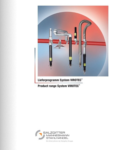
Lieferprogramm System VIROTEC ®<br />
Product range System VIROTEC ®<br />
MANNESMANN<br />
STAHLHANDEL<br />
Ein Unternehmen der Salzgitter Gruppe
1.0<br />
2.0<br />
3.0<br />
4.0<br />
5.0<br />
6.0<br />
7.0<br />
8.0<br />
9.0<br />
10.0<br />
System VIROTEC ® , Produktpalette<br />
System VIROTEC ® , range of products<br />
Sprinklerschelle/Abschirmhaube<br />
Sprinkler clamp-T/Shielding cap<br />
Fallrohr/Telerohr/Flexarm ®<br />
Drop nipple/Telescope pipe/Flexarm ®<br />
Flexschlauch/Halterung<br />
Flex hose/Fixture<br />
Kupplung/Reduzierkupplung/Anbohrschelle/Sprinklerschelle<br />
Coupling/Reduce coupling/Clamp-T/Sprinkler clamp-T<br />
Bogen/T-Stück/Endkappe<br />
Elbow/Tee/Cap<br />
Flansch/Reduzierung/T-Rohr<br />
Flange/Reducer/T-pipe<br />
Wartungseinheit/Sprinklerreservebox<br />
Maintenance unit/Sprinkler reserve box<br />
Nutmaschine/Bohrvorrichtung/Kreislochsäge/Gewindedichtmittel/Gleitmittel<br />
Grooving machine/Drilling device/Circular keyhole saw/Threat sealant/Lubricants<br />
Sonderteile/Rohrvorfertigung<br />
Special parts/Pipe prefabrication<br />
Inhalt<br />
Contents
1.0 System VIROTEC ® , Produktpalette<br />
1.0 System VIROTEC ® , range of products<br />
1.1 System VIROTEC ®<br />
System VIROTEC ®<br />
1.2 Bauteile für Montage des Rohrnetzes (Haupt- und Verteilerleitungen)<br />
Component parts for the assembly of the pipeline network (main pipeline and<br />
branch line)<br />
1.3 Bauteile für Montage von der Verteilerleitung zum Sprinklerkopf (Rohrauswinkelung)<br />
Component parts for the assembly of the branch line for the sprinkler head<br />
(arm over pipe)<br />
1.4 Bauteile als Ergänzung zum Rohrnetz<br />
Additional component parts for the pipe system<br />
1.5 Montagezubehör<br />
Mounting accessories<br />
1.0
Stand: 1/08<br />
System VIROTEC ®<br />
Produkte die verbinden!<br />
System VIROTEC ® ist eine abgestimmte Produktpalette von Rohrverbindungselementen,<br />
für den Einsatz im Rohrleitungsbau, insbesondere<br />
für den Sprinkleranlagenbau (automatische, stationäre<br />
Feuerlöschanlagen).<br />
Es <strong>handel</strong>t sich hier um innovative und leistungsfähige Produkte<br />
mit folgenden Merkmalen:<br />
– Einfache und schnelle Montage<br />
– Hohe Funktionssicherheit<br />
– Umfangreiches Sortiment<br />
– Ansprechendes Design und hochwertige Verarbeitung<br />
Unsere Bauteile sind beim VdS Schadenverhütung in Köln und bei<br />
FM (Factory Mutual) in USA geprüft und anerkannt. Die Entwicklung,<br />
Produktion und der Vertrieb der Produkte erfolgt unter den<br />
Bedingungen eines anerkannten QM-Systems gemäß DIN EN ISO<br />
9001. Einige Produkte sind durch internationale Patente und/oder<br />
Gebrauchsmuster geschützt.<br />
Ein qualifiziertes und leistungsfähiges Team sorgt für eine optimale<br />
Kundenberatung und die reibungslose und schnelle Abwicklung<br />
der Kundenaufträge.<br />
In Verbindung mit dem umfangreichen Rohrsortiment und der<br />
Rohrvorfertigung sind wir Komplettanbieter für Ihr Rohrleitungsnetz.<br />
System VIROTEC ®<br />
Products that connect!<br />
1.1<br />
System VIROTEC ®<br />
System VIROTEC ®<br />
System VIROTEC ® is a well arranged product array of pipe joint<br />
elements for use in pipeline construction, particularly suitable for<br />
the manufacture of sprinkler systems (automatic, stationary fire<br />
extinguishing equipment).<br />
These products are efficient and innovative and feature:<br />
– Easy and quick assembly<br />
– High degree of functional safety<br />
– Comprehensive range<br />
– Attractive design and high-quality workmanship<br />
Our component parts are tested and acknowledged at VdS<br />
Schadenverhütung in Cologne and FM (Factory Mutual) in USA.<br />
All products are developed, manufactured and distributed in conformance<br />
with a recognised QA system as per DIN EN ISO 9001.<br />
Some products are protected by international patents and/or<br />
patented designs.<br />
Our qualified and efficient team offers the best possible consultation<br />
to customers and ensures quick and smooth processing of<br />
the sales orders.<br />
With our extensive range of pipes and pre-fabricated pipes, we are<br />
a one stop shop for all products relating to your pipeline system.<br />
Standort Eiterfeld
Stand: 1/08<br />
1.2<br />
Bauteile für Montage des Rohrnetzes (Haupt- und Verteilerleitungen)<br />
Bauteile für Montage des Rohrnetzes (Haupt- und Verteilerleitungen)<br />
Rohrkupplung<br />
(siehe Katalog Abschnitt 5.1–5.2)<br />
Kupplung für genutete Rohre aus Stahl, verzinkt oder lackiert, in<br />
Ausführung starr oder flexibel, Durchmesser 33,7 mm (1”) bis<br />
323,9 mm (12”).<br />
Formteile<br />
(siehe Katalog Abschnitt 6.1–6.6)<br />
Bestehend aus Bogen 22,5°/45°/90°, T-Stück, Reduzierung, Endkappe,<br />
verzinkt oder lackiert, Durchmesser 33,7 mm (1”) bis<br />
323,9 mm (12”).<br />
Anbohrschelle<br />
(siehe Katalog Abschnitt 5.4–5.5)<br />
In den Varianten mit Nut- oder mit Gewindeanschluss, verzinkt<br />
oder lackiert, Durchmesser 60,3 mm (2”) bis 219,1 mm (8”) und<br />
Abgänge 33,7 mm (1”) bis 114,3 mm (4”).<br />
Component parts for the assembly of the pipeline network<br />
(main pipeline and branch line)<br />
Component parts for the assembly of the pipeline network<br />
(main pipeline and branch line)<br />
Pipe coupling<br />
(See catalogue, section 5.1–5.2)<br />
Coupling for grooved steel pipes, galvanized or painted, rigid or<br />
flexible model, diameter ranging from 33.7 mm (1”) to 323.9 mm<br />
(12”).<br />
Formed parts<br />
(See catalogue, section 6.1–6.6)<br />
Including elbow 22.5°/45°/90°, T-piece, reducing joint, end cap,<br />
galvanized or painted, diameter ranging from 33.7 mm (1”) to<br />
323.9 mm (12”).<br />
Clamp-T<br />
(See catalogue, section 5.4–5.5)<br />
Available in two variants – with grooved connection or threaded<br />
connection, galvanized or painted, diameter ranging from<br />
60.3 mm (2”) to 219.1 mm (8”) and outlet diameters from<br />
33.7 mm (1”) to 114.3 mm (4”).
Stand: 1/08<br />
1.2<br />
Bauteile für Montage des Rohrnetzes (Haupt- und Verteilerleitungen)<br />
Component parts for the assembly of the pipeline network<br />
(main pipeline and branch line)<br />
Reduzierkupplung, Reduzierstücke, Flansche<br />
(siehe Katalog Abschnitt 5.3 und 7.1–7.4)<br />
Jeweils verzinkt oder lackiert, Durchmesser 33,7 mm (1”) bis<br />
323,9 mm (12”).<br />
Reducing coupling, reduction pieces, flanges<br />
(See catalogue, section 5.3 and 7.1–7.4)<br />
Each in galvanized or painted design, diameter ranging from<br />
33.7 mm (1”) to 323.9 mm (12”).
Stand: 1/08<br />
1.3<br />
Bauteile für Montage von der Verteilerleitung zum Sprinklerkopf (Rohrauswinkelung)<br />
Component parts for the assembly of the branch line for the sprinkler head<br />
(arm over pipe)<br />
Bauteile für Montage von der Verteilerleitung zum Sprinklerkopf<br />
(Rohrauswinkelung)<br />
Sprinklerschelle<br />
(siehe Katalog Abschnitt 2.1 und 5.6)<br />
Anbohrschelle für den Einsatz in Sprinkleranlagen, zur Versorgung<br />
von jeweils einem Sprinklerkopf. Typ VTS, mit Oberfläche verzinkt,<br />
für Rohrdurchmesser 33,7 mm (1”) bis 60,3 mm (2”) und mit Gewindeanschluss<br />
3 /8”, 1 /2”, 3 /4”, 1” IG. Typ Gruvlok 7043, mit Oberfläche<br />
verzinkt oder rot lackiert, für Rohrdurchmesser 42,4 mm<br />
(1 1 /4”) bis 76,1 mm (2 1 /2”) und mit Gewindeanschluss 1 /2”, 3 /4”, 1”<br />
IG.<br />
Fallrohr<br />
(siehe Katalog Abschnitt 3.1)<br />
für den Einsatz in Sprinkleranlagen, ein- oder beidseitig reduziert,<br />
Oberfläche grundiert oder verzinkt, in den Abmessungen 3 /4” und<br />
1”, mit Sprinkleranschluss 3 /8”, 1 /2”, 3 /4” IG, in den Längen 500 und<br />
1.000 mm.<br />
Telerohr<br />
(siehe Katalog Abschnitt 3.2–3.3)<br />
Längenverstellbares Fallrohr Typ VS, VSI, VSN für den Einsatz in<br />
Sprinkleranlagen, Oberfläche KTL-beschichtet schwarz, Abmessung<br />
1” AG oder IG x 1 /2” IG, in den Längen 100 bis 1.000 mm,<br />
Verstellung 60 oder 100 mm.<br />
Component parts for the assembly of the branch line for the<br />
sprinkler head (arm over pipe)<br />
Sprinkler clamp-T<br />
(See catalogue, section 2.1 and 5.6)<br />
Clamp-T for use in sprinkler systems, each for supply of one<br />
sprinkler head. Type VTS, with galvanized surface, for pipe diameter<br />
ranging from 33,7 mm (1”) to 60,3 mm (2”) and with threaded<br />
connection 3 /8”, 1 /2”, 3 /4”, 1” IG. Type Gruvlok 7043, with galvanized<br />
or red painted surface, for pipe diameter ranging from 42,4<br />
mm (1 1 /4”) to 76,1 mm (2 1 /2”) and with threaded connection 1 /2”,<br />
3 /4”, 1” IG.<br />
Drop nipple<br />
(See catalogue, section 3.1)<br />
For use in sprinkler systems, reduced from one or both sides,<br />
galvanized surface or surface with primer coating, available in<br />
dimensions 3 /4” and 1”, with sprinkler connection 3 /8”, 1 /2”, 3 /4” IG,<br />
available in lengths 500 and 1,000 mm.<br />
Telescope pipe<br />
(See catalogue, section 3.2–3.3)<br />
Adjustable drop nipple length, type VS, VSI, VSN for use in sprinkler<br />
systems, surface with black KTL coat (cataphoretic painting),<br />
dimension 1” AG or IG x 1 /2” IG, in lengths from 100 to 1,000<br />
mm, adjustment 60 or 100 mm.
Stand: 1/08<br />
1.3<br />
Bauteile für Montage von der Verteilerleitung zum Sprinklerkopf (Rohrauswinkelung)<br />
Component parts for the assembly of the branch line for the sprinkler head<br />
(arm over pipe)<br />
Flexarm ®<br />
(siehe Katalog Abschnitt 3.4)<br />
Verstellbare Rohrauswinklung (durch Drehgelenke), Typ FL1 und<br />
FL2, für den Einsatz in Sprinkleranlagen, Oberfläche verzinkt,<br />
Abmessung 1” AG x 1” IG.<br />
Flexschlauch und Halterung<br />
(siehe Katalog Abschnitt 4.1–4.5)<br />
Hochflexibler und Druckstabiler Wellschlauch aus Edelstahl mit<br />
Ummantelung (Drahtgeflecht), Typ VX-G und VX-S, für den Einsatz<br />
in Sprinkleranlagen, Abmessung 3 /4” und 1” AG mit Sprinkleranschluss<br />
1 /2” IG, Halterung für Flexschlauch Typ VX-SH sowie VX-<br />
GH (für abgehängte Deckensysteme) und VX-UH (Universalhalter),<br />
Oberfläche verzinkt.<br />
Flexarm ®<br />
(See catalogue, section 3.4)<br />
Adjustable angular deflection (due to pivoting joints), type FL1<br />
and FL2, for use in sprinkler systems, galvanized surface, dimension<br />
1” AG x 1” IG.<br />
Flex hose and ficture<br />
(See catalogue, section 4.1–4.5)<br />
Extremely flexible and pressure-resistant corrugated stainless<br />
steel hose with casing (wire mesh), type VX-G and VX-S, for use<br />
in sprinkler systems, dimension 3 /4” and 1” AG with sprinkler connection<br />
1 /2” IG, Holder for flexible hose, type VX-SH and VX-GH<br />
(for suspended ceiling systems) and VX-UH (universal bracket),<br />
galvanized surface.
Stand: 1/08<br />
Bauteile als Ergänzung zum Rohrnetz<br />
Abschirmhaube<br />
(siehe Katalog Abschnitt 2.2–2.3)<br />
In den Varianten Standard, Doppelsprinkler und Universal, für den<br />
Einsatz in Sprinkleranlagen im Regalbereich, Oberfläche verzinkt,<br />
für Sprinkler 3 /8”, 1 /2”, 3 /4”.<br />
Wartungseinheit<br />
(siehe Katalog Abschnitt 8.1)<br />
Zum Ablassen von Kondenswasser im Rohrnetz, in den Varianten<br />
mit und ohne Einfüllstutzen für Frostschutzmittel, Oberfläche verzinkt.<br />
1.4<br />
Bauteile als Ergänzung zum Rohrnetz<br />
Additional component parts for the pipe system<br />
Additional component parts for the pipe system<br />
Shielding cap<br />
(See catalogue, section 2.2–2.3)<br />
Available in standard, dual sprinkler and universal variants, for<br />
use in sprinkler systems in the storage rack area, galvanized surface,<br />
for 3 /8”, 1 /2”, 3 /4” sprinklers.<br />
Maintenance unit<br />
(See catalogue, section 8.1)<br />
For draining condensation water in the pipe system, two variants<br />
– with and without filler necks for anti-freezing agents, galvanized<br />
surface.
Stand: 1/08<br />
Montagezubehör<br />
Nutmaschine<br />
(siehe Katalog Abschnitt 9.1)<br />
Halbautomatische Nutmaschine Typ GROOVER 324 für den mobilen<br />
Einsatz, mit elektrischen Antrieb 220V und hydraulischer Handpumpe,<br />
für Rohrdurchmesser von 33,7 mm (DN25/1”) bis 219 mm<br />
(DN200/8”) und maximaler Wandungsstärke von 8 mm.<br />
Rohrständer verstellbar, passend zur Nutmaschine.<br />
.<br />
Bohrvorrichtung<br />
(siehe Katalog Abschnitt 9.2)<br />
Typ 1 für einfaches und sicheres einbringen der Bohrungen<br />
Durchmesser 24 mm/32 mm für Montage der Sprinklerschellen.<br />
Mounting accessories<br />
1.5<br />
Montagezubehör<br />
Mountin accessories<br />
Grooving machine<br />
(See catalogue, section 9.1)<br />
Semi-automatic grooving machine type GROOVER 324 for<br />
mobile use, with electro drive 220 V and hydraulic hand pump,<br />
for diameter from 33,7 mm (DN25/1”) to 219 mm (DN200/8”) and<br />
maximum wall thickness of 8 mm.<br />
Pipe support adjustable, suitable for grooving machine.<br />
Drilling device<br />
(See catalogue, section 9.2)<br />
Type 1 for easy and safe drilling of holes, diameter 24 mm/<br />
32 mm, for the assembly of VTS sprinkler clamps.
Stand: 1/08<br />
1.5<br />
Montagezubehör<br />
Mountin accessories<br />
Kreislochsägen<br />
(siehe Katalog Abschnitt 9.3)<br />
In unterschiedlichen Abmessungen, für Sprinklerschellen und<br />
sonstige Anbohrschellen.<br />
Gewindedichtmittel<br />
(siehe Katalog Abschnitt 9.4)<br />
Typ VFD in 50 ml/250 ml Flasche, zum sicheren und einfachen<br />
abdichten von Rohrgewinden.<br />
Gleitmittel<br />
(siehe Katalog Abschnitt 9.5)<br />
Montagefett für Rohrkupplungen in verschiedenen Ausführungen.<br />
Circular hole saws<br />
(See catalogue, section 9.3)<br />
Available in different dimensions, for sprinkler clamps and other<br />
clamp-T.<br />
Thread sealant<br />
(See catalogue, section 9.4)<br />
Type VFD in 50 ml/250 ml bottle, for safe and easy sealing of<br />
pipe threads.<br />
Lubricant<br />
(See catalogue, section 9.5)<br />
Assembly lubricant for pipe fittings, available in different variants.
2.0 Sprinklerschelle/Abschirmhaube<br />
2.0 Sprinkler clamp-T/Shielding cap<br />
2.1 Sprinklerschelle VTS<br />
Sprinkler clamp-T VTS<br />
2.2 Abschirmhaube Standard/für Doppelsprinkler<br />
Shielding cap standard/for double sprinklers<br />
2.3 Abschirmhaube Universal<br />
Shielding cap universal<br />
Beispiel von VTS-Anbohrschelle und Abschirmhaube<br />
2.0
Stand: 1/08<br />
VIROTEC ® -VTS einfache Montage, spart Zeit, senkt Kosten<br />
Das VIROTEC ® -VTS ist ein Sonderfitting für den Einsatz in ortsfesten<br />
Wasserlöschanlagen und dem allgemeinen Rohrleitungsbau.<br />
Das Bauteil ermöglicht die einfache und schnelle Fertigung von<br />
Abgängen an durchgängigen Rohrleitungen, ohne diese auftrennen<br />
zu müssen.<br />
Bei allen Rohrdurchmessern (1” – 2”) und Abgangsgrößen 3 /8” – 1”)<br />
wird mit einem Bohrungsdurchmesser (24 +0,5 mm) gearbeitet.<br />
Montageanweisung<br />
1. Bohrung mit Durchmesser 24 +0,5 mm bohren, entgraten und<br />
von Bohrspänen säubern.<br />
2. Dichtung auf richtigen Sitz prüfen und VTS aufsetzen.<br />
3. Sechskantschrauben gleichmäßig anziehen (ca. 20 Nm).<br />
4. Bauteil funktionsfertig.<br />
Funktion<br />
Das VIROTEC ® -VTS besteht aus folgenden Bauteilen:<br />
– Pos. 1 Verbindungselement (Gussteil, verzinkt)<br />
– Pos. 2 Halbschelle (Gussteil, verzinkt)<br />
– Pos. 3 Sechskantschraube M8 (8.8, verzinkt)<br />
– Pos. 4 Poly-U-Scheibe (Kunststoff)<br />
– Pos. 5 Flachdichtung (EPDM)<br />
Das VIROTEC ® -VTS wird montagefertig ausgeliefert und kann<br />
somit auf einfachste Weise auf ein Rohr mit vorgefertigter Bohrung<br />
montiert werden. Die Zentrierung am Verbindungselement erleichtert<br />
bei der Montage die Ausrichtung des Bauteils. Durch gleichmäßiges<br />
Anziehen der Schrauben wird die Flachdichtung verpresst<br />
und dichtet somit das System druckdicht ab.<br />
VIROTEC ® -VTS easy mounting, save time, reduces costs<br />
VIROTEC ® -VTS is a special fitting for use in fixed, stationary<br />
water systems for extinguishing fires ans general pipe laying and<br />
installation. The component enables fast and easy production of<br />
outlets at through pipes, without having to cut them.<br />
One bore diameter (24 +0,5 mm) is used for all pipe diameters<br />
(1” – 2”) and outlet pipe sizes ( 3 /8” – 1”).<br />
Mounting instructions<br />
1. Drill hole with diameter 24 +0,5 mm, deburr and clean off drilling<br />
chips.<br />
2. Check seal for correct fit and put on VTS.<br />
3. Evenly tighten hexagonal screws (approx 20 Nm).<br />
4. Component ready for use.<br />
Function<br />
The VIROTEC ® -VTS consists of the following components:<br />
– Item 1 Connection element (casting, zinced)<br />
– Item 2 Half-clip (casting, zinced)<br />
– Item 3 Hexagonal screw M8 (8.8, zinced)<br />
– Item 4 Poly plain washer (plastic)<br />
– Item 5 Flat seal (EPDM)<br />
2.1<br />
Sprinklerschelle VTS<br />
Sprinkler clamp-T VTS<br />
The VIROTEC ® -VTS ist supplied ready to install and can therefore<br />
be easily fitted onto a pipe with prefabricated drill hole. The<br />
centring on the connector makes it easier to align the component<br />
during installation. The flat seal ist pressed by uniformly tightening<br />
the screws and therefore tightly seals the system.
Stand: 1/08<br />
2.1<br />
Sprinklerschelle VTS<br />
Sprinkler clamp-T VTS<br />
Artikel-Nr. Rohrgröße Ab- D3 B1 B2 H2 H3 Gew. VPE<br />
gang<br />
(D1) (D2) (mm) (mm) (mm) (mm) (mm) (kg) (St.)<br />
Item- pipesize outlet D3 B1 B2 H2 H3 we. unit<br />
number (D1) (D2) (mm) (mm) (mm) (mm) (mm) (kg) (pcs.)<br />
100-251010 DN 25 3 /8” 25 85 48 23,5 29 0,25 100<br />
100-251015 DN 25 1 /2” 25 85 48 23,5 29 0,24 100<br />
100-251020 DN 25 3 /4” 31 85 53 23,5 39,5 0,29 100<br />
100-251025 DN 25 1” 37 85 58 23,5 43 0,32 75<br />
100-321010 DN 32 3 /8” 25 92 48 28 33 0,26 100<br />
100-321015 DN 32 1 /2” 25 92 48 28 33 0,25 100<br />
100-321020 DN 32 3 /4” 31 92 53 28 43,5 0,32 75<br />
100-321025 DN 32 1” 37 92 58 28 47,5 0,40 70<br />
100-401010 DN 40 3 /8” 25 97 48 31 36 0,28 75<br />
100-401015 DN 40 1 /2” 25 97 48 31 36 0,28 75<br />
100-401020 DN 40 3 /4” 31 97 53 31 46,5 0,33 75<br />
100-401025 DN 40 1” 37 97 58 31 50,5 0,42 60<br />
100-501010 DN 50 3 /8” 25 112 48 37 42 0,32 60<br />
100-501015 DN 50 1 /2” 25 112 48 37 42 0,31 60<br />
100-501020 DN 50 3 /4” 31 112 53 37 52,5 0,37 60<br />
100-501025 DN 50 1” 37 112 58 37 56,5 0,45 50<br />
Technische Daten<br />
– Oberfläche: verzinkt<br />
– Gewicht: siehe Tabelle<br />
– Verpackungseinheit: siehe Tabelle<br />
– Gewinde: Rohrgewinde Rp 3 /8”, 1 /2”, 3 /4”, 1”<br />
gemäß DIN 2999 (ISO 7-1)<br />
– Einsatztemperatur: - 20 °C bis 110 °C<br />
– Betriebsdruck: PN 16 (16 bar)<br />
– Bemerkung: zur direkten Versorgung von je einem<br />
Sprinkler bis zu einem K-Faktor von 80<br />
– Schutzrechte: Patent/GbM<br />
Zulassungen<br />
FM<br />
APPROVED<br />
VTS<br />
Technical data<br />
– Surface: zinced<br />
– Weight: see table<br />
– Packaging unit: see table<br />
– Thread: Pipe thread Rp 3 /8”, 1 /2”, 3 /4”, 1”<br />
in accordance with DIN 2999<br />
– Use temperature: - 20 °C to 110 °C<br />
– Operating pressure: PN 16 (16 bar)<br />
– Notes: for direct supply of one sprinkler each<br />
up to a K-factor of 80<br />
– Protective rights: Patent/Utility model<br />
Approvals<br />
H3<br />
B2<br />
H2<br />
approved products<br />
D3<br />
D2<br />
ø19<br />
(bei 3/8" ø15)<br />
ø24<br />
D1<br />
B1<br />
+0,5<br />
-0<br />
FM<br />
APPROVED<br />
SW13<br />
1<br />
5<br />
3<br />
4<br />
2
Stand: 1/08<br />
VIROTEC ® -Abschirmhauben richtungsweisend für Sprinkleranlagen<br />
Die VIROTEC ® -Abschirmhauben sind für den Einsatz in Regallager<br />
und Hochregalanlagen bei ortsfesten Wasserlöschanlagen<br />
bestimmt. Das Bauteil dient als Schutz für hängende Regalsprinkler,<br />
um ihre gegenseitige Kühlung zu verhindern.<br />
Montageanweisung<br />
VIROTEC ® -Abschirmhauben sind durch die integrierte Federsicherung<br />
sehr einfach zu montieren. Sie werden einfach über das<br />
Gewinde des Sprinklers geschoben und beim Einschrauben des<br />
Sprinklers verspannt. Dadurch sind die Abschirmhauben gegen<br />
Verdrehen und Kippen gesichert.<br />
Beim Einsatz im Bereich von Doppelsprinklern sind zwei abgewinkelte<br />
Abschirmhauben zu verwenden, welche so auszurichten und<br />
zu fixieren sind, dass eine gegenseitige Kühlung verhindert wird.<br />
Funktion<br />
Die VIROTEC ® -Abschirmhaube besteht aus folgenden Teilen:<br />
– Pos. 1 Prallteller (Stahlblech, verzinkt)<br />
– Pos. 2 Federsicherung (Federstahl, verzinkt)<br />
Die VIROTEC ® -Abschirmhaube wird aus verzinktem Stahlblech<br />
mit integrierter Federsicherung hergestellt. Die VIROTEC ® -<br />
Abschirmhaube ist für Sprinkler 3 /8”, 1 /2” und 3 /4” in Standardausführung<br />
bzw. in abgewinkelter Form (für Doppelsprinkler) erhältlich.<br />
2.2<br />
Abschirmhaube Standard/für Doppelsprinkler<br />
Shielding cap standard/for double sprinklers<br />
VIROTEC ® -shielding cap directive for sprinkler systems<br />
VIROTEC ® -shielding cap covers are intended for use in high-bay<br />
racking and high-bay racking systems with fixed, stationary water<br />
systems for extinguishing fires. The component serves as a protection<br />
for suspended shelf sprinklers, in order to prevent their<br />
mutual cooling.<br />
Mounting instruction<br />
VIROTEC ® -shielding cap covers are very easy to install due to<br />
the integrated spring retainers. They are simply pushed over the<br />
thread of the sprinkler and clamped when the sprinkler is<br />
screwed in. This secures the screening covers against twisting<br />
and tilting.<br />
When used for double sprinklers, two angled screening covers<br />
are to be used, which are to be aligned and fixed to prevent<br />
mutual cooling.<br />
Function<br />
VIROTEC ® -shielding cap covers consist of the following parts:<br />
– Item 1 impact plate (sheet steel, zinced)<br />
– Item 2 spring retainer (spring steel, zinced)<br />
VIROTEC ® -shielding cap covers are made from zinced sheet<br />
steel with integrated spring retainer. VIROTEC ® -shielding cap<br />
covers are available for 3 /8”, 1 /2” and 3 /4” sprinklers in standard<br />
design and in angled form (for double sprinklers).
Stand: 1/08<br />
2.2<br />
Abschirmhaube Standard/für Doppelsprinkler<br />
Shielding cap standard/for double sprinklers<br />
Bauteil Artikel-Nr. Sprinklergröße<br />
Abschirmhaube Standard 205-138 3 /8”<br />
205-112<br />
1 /2”<br />
205-134<br />
3 /4”<br />
Abschirmhaube für Doppelsprinkler 205-238 3 /8”<br />
205-212<br />
1 /2”<br />
205-234<br />
3 /4”<br />
Technische Daten<br />
– Oberfläche: verzinkt<br />
– Material: Stahlblech<br />
– Nenngröße: für Sprinkler 3 /8”, 1 /2” und 3 /4”<br />
– Gewicht: 0,080 kg<br />
– Verpackungseinheit: 250 Stück<br />
– Schutzrechte: GbM<br />
Zulassungen<br />
VdS- und FM einsetzbar<br />
Abschirmhaube<br />
Standard<br />
Shielding cap<br />
standard<br />
3 /8“<br />
1 /2“<br />
3 /4“<br />
Ø 165<br />
2<br />
1<br />
Component Item number Sprinkler size<br />
Shielding cap standard 205-138 3 /8”<br />
205-112<br />
1 /2”<br />
205-134<br />
3 /4”<br />
Shielding cap for double sprinklers 205-238 3 /8”<br />
205-212<br />
1 /2”<br />
205-234<br />
3 /4”<br />
Technical data<br />
– Surface: zinced<br />
– Material: sheet steel<br />
– Nominal size: for Sprinkler 3 /8”, 1 /2” and 3 /4”<br />
– Weight: 0,080 kg<br />
– Packaging unit: 250 pieces<br />
– Protective rights: GbM<br />
Approvals<br />
VdS- and FM applicable<br />
Abschirmhaube für<br />
Doppelsprinkler<br />
Shielding cap for<br />
double sprinklers<br />
3 /8“<br />
1 /2“<br />
3 /4“<br />
Ø 165<br />
2<br />
1
Stand: 1/08<br />
VIROTEC ® -Abschirmhauben Universal richtungsweisend für<br />
Sprinkleranlagen<br />
Die VIROTEC ® -Abschirmhauben Universal sind für den Einsatz in<br />
Regallager und Hochregalanlagen bei ortsfesten Wasserlöschanlagen<br />
bestimmt. Das Bauteil dient als Schutz für hängende Regalsprinkler,<br />
um ihre gegenseitige Kühlung zu verhindern.<br />
Montageanweisung<br />
VIROTEC ® -Abschirmhauben Universal sind durch die integrierte<br />
Federsicherung sehr einfach zu montieren. Sie werden einfach<br />
über das eingedichtete Gewinde des Sprinklers geschoben und<br />
beim Einschrauben des Sprinklers verspannt. Dadurch sind die<br />
Abschirmhauben gegen Verdrehen und Kippen gesichert.<br />
Funktion<br />
Die VIROTEC ® -Abschirmhaube Universal ermöglicht durch ihre<br />
Form, neben der vertikalen Abschirmung auch eine horizontale<br />
Abschirmung im Umkreis von 360° und ist daher universell einsetzbar.<br />
Die Anwendung erfolgt, zum Beispiel im verdichteten<br />
Sprinklerschutz, wie in Hochregalsystemen oder ähnlichen Einsatzfällen.<br />
Die VIROTEC ® -Abschirmhaube Universal wird aus verzinktem<br />
Stahlblech mit integrierter Federsicherung hergestellt und ist für<br />
hängende Sprinkler 3 /8”, 1 /2” und 3 /4” erhältlich.<br />
Die VIROTEC ® -Abschirmhaube Universal besteht aus folgenden<br />
Teilen:<br />
– Pos. 1 Prallteller (Stahlblech, verzinkt)<br />
– Pos. 2 Federsicherung (Federstahl, verzinkt)<br />
2.3<br />
Abschirmhaube Universal<br />
Shielding cap universal<br />
VIROTEC ® Universal shielding cap directive for sprinkler<br />
systems<br />
VIROTEC ® universal shielding capcovers are intended for use in<br />
high-bay racking and high-bay racking systems for fixed, stationary<br />
water systems for extinguishing fires. The component serves<br />
to protect hanging shelf sprinklers in order to prevent their mutual<br />
cooling.<br />
Mounting instruction<br />
VIROTEC ® -shielding cap universal covers are very easy to install<br />
due to the integrated spring retainer. They are simply pushed<br />
over the sealed thread of the sprinkler and clamped when the<br />
sprinkler is screwed in. This secures the screening covers against<br />
twisting and tilting.<br />
Function<br />
Due to its shape, the VIROTEC ® -shielding cap universal cover not<br />
only enables vertical screening but 360° horizontal screening and<br />
is therefore suitable for universal use. For example, it is used in<br />
compact sprinkler protection, such as in high-bay racking systems<br />
or similar uses.<br />
VIROTEC ® -shielding cap universal covers are made from zinced<br />
sheet steel with integrated spring retainer and are available for<br />
hanging 3 /8”, 1 /2” and 3 /4” sprinklers.<br />
VIROTEC ® -shielding cap universal covers are made up of the following<br />
parts:<br />
– Item 1 impact plate (sheet steel, zinced)<br />
– Item 2 spring retainer (spring steel, zinced)
Stand: 1/08<br />
2.3<br />
Abschirmhaube Universal<br />
Shielding cap universal<br />
Bauteil Artikel-Nr. Sprinklerdurchgang<br />
Abschirmhaube Universal 205-338 3 /8”<br />
205-312<br />
1 /2”<br />
205-334<br />
3 /4”<br />
Technische Daten<br />
– Oberfläche: verzinkt<br />
– Material: Stahlblech<br />
– Nenngröße: für Sprinkler 3 /8”, 1 /2” und 3 /4”<br />
– Gewicht: 0,080 kg<br />
– Verpackungseinheit: 200 Stück<br />
– Schutzrechte: GbM<br />
Zulassungen<br />
Abschirmhaube<br />
Universal<br />
Shielding cap<br />
universal<br />
3/8“<br />
1/2“<br />
3/4“<br />
Ø 160 H 31<br />
Component Item number Sprinkler passage<br />
Shielding cap universal 205-338 3 /8”<br />
205-312<br />
1 /2”<br />
205-334<br />
3 /4”<br />
Technical data<br />
– Surface: zinced<br />
– Material: sheet steal<br />
– Nominal size: for Sprinkler 3 /8”, 1 /2” and 3 /4”<br />
– Weight: 0,080 kg<br />
– Packaging unit: 200 pieces<br />
– Protective rights: GbM<br />
Approvals<br />
approved products<br />
Hersteller Größe Typ K-Faktor H +/-2 (mm)<br />
Manufacturer Size Type K-factor H +/-2 (mm)<br />
Tyco 3 /8” TY 22… 57 4<br />
1 /2” TY 32… 80 8<br />
3 /4” TY 42… 115 8<br />
Reliable 3 /8” F1… 57 9<br />
1 /2” F1… 80 9<br />
3 /4” F1… 115 9<br />
GW 1 /2” Angus-S… 80 2<br />
3 /4” Angus-S… 115 2<br />
Viking 1 /2” M… 80 8<br />
3 /4” M… 115 8<br />
Jomos 3 /8” JA… 57 0<br />
1 /2” JB… 80 0<br />
3 /4” JC… 115 0
3.0 Fallrohr/Telerohr/Flexarm ®<br />
3.0 Drop nipple/Telescope pipe/Flexarm ®<br />
3.1 Fallrohr<br />
Drop nipple<br />
3.2 Telerohr VS<br />
Telescope pipe VS<br />
3.3 Telerohr VSI, VSN<br />
Telescope pipe VSI, VSN<br />
3.4 Flexarm ® FL1, FL2<br />
Flexarm ® FL1, FL2<br />
Beispiel von Fallrohr, Telerohr und Flexarm ®<br />
3.0
Stand: 1/08<br />
VIROTEC ® -Fallrohr Durchmesser 3 /4” und 1”<br />
Das VIROTEC ® -Fallrohr ist ein Sprinklerrohr, als Steig- oder Fallrohr<br />
einsetzbar, zum direkten Einschrauben von Sprinklern in ortsfesten<br />
Wasserlöschanlagen. Es wird in den Rohrabmessungen 3 /4“<br />
und 1”, in den Längen 0,5 m und 1,0 m, einseitig oder beidseitig<br />
reduziert und mit Gewindeabgängen 3 /8“, 1 /2” bzw. 3 /4” angeboten.<br />
Montageanweisung<br />
1. Erforderliche Bauteillänge ermitteln.<br />
2. VIROTEC ® -Fallrohr auf die erforderliche Länge kürzen.<br />
3. Außengewinde schneiden und eindichten.<br />
4. VIROTEC ® -Fallrohr in den entsprechend Fitting einschrauben.<br />
5. Sprinkler eindichten und in das Innengewinde einschrauben<br />
(max. 25 Nm Anzugsdrehmoment).<br />
6. Nach Sprinklermontage Sichtprüfung auf Risse an der Reduzierung.<br />
7. Bauteil funktionsfertig.<br />
Funktion<br />
Das VIROTEC ® -Fallrohr wird aus geschweißtem Gewinderohr<br />
nach DIN 2440 hergestellt. Es ist in grundierter bzw. verzinkter<br />
Ausführung und in den Standardlängen 0,5 und 1,0 lieferbar.<br />
Das VIROTEC ® -Fallrohr wird auf der Baustelle auf die entsprechende<br />
Länge abgeschnitten und mit einem Außengewinde versehen.<br />
Beim beidseitig reduzierten Rohr ergeben sich durch das<br />
Trennen zwei Sprinklerrohre.<br />
3.1<br />
Fallrohr<br />
Drop nipple<br />
VIROTEC ® -Drop nipple in diameters 3 /4” and 1”<br />
The VIROTEC ® -drop nipple is a pipe which can be used as a<br />
riser or downpipe for directly screwing in sprinklers in fixed, stationary<br />
water systems for extinguishing fires. It is available in the<br />
pipe dimensions 3 /4” and 1”, in the lengths 0.5 m and 1.0 m, with<br />
one-sided or double-sided reduction and with 3 /8”, 1 /2” and 3 /4”<br />
threaded outlet connections.<br />
Mounting instruction<br />
1. Determine the required component length.<br />
2. Shorten the VIROTEC ® -drop nipple to the required length.<br />
3. Cut the outer thread and seal.<br />
4. Screw the VIROTEC ® -drop nipple in the relevant fitting.<br />
5. Seal the sprinkler and screw into the inner thread<br />
(max. 25 Nm tightening torque).<br />
6. After fitting the sprinkler, visually inspect for cracks at the<br />
reducer.<br />
Function<br />
The VIROTEC ® -drop nipple is made as a welded threaded pipe<br />
to DIN 2440. It is available in primed and zinced versions and in<br />
the standard lengths 0.5 and 1.0 m.<br />
The VIROTEC ® -drop nipple is cut to the required length on building<br />
site and equipped with an outer thread. In the double-sided<br />
reduced pipe the cutting produces two drop nipples.
Stand: 1/08<br />
3.1<br />
Fallrohr<br />
Drop nipple<br />
Technische Daten<br />
– Oberfläche: grundiert oder verzinkt<br />
– Material: Gewinderohr gemäß DIN 2440<br />
– Gewicht:<br />
3 /4” 1.500 mm lang – 0,8 kg<br />
3 /4” 1.000 mm lang – 1,6 kg<br />
1” 1.500 mm lang – 1,2 kg<br />
1” 1.000 mm lang – 2,4 kg<br />
– Sonderanfertigung: Abweichende Oberflächen und Längen<br />
auf Anfrage<br />
Zulassungen<br />
VdS- und FM einsetzbar<br />
Fallrohr 3 /4”<br />
Drop nipple 3 /4”<br />
Längenanpassung<br />
auf der Baustelle oder<br />
in der Vorfertigung<br />
(ergibt zwei Fallrohre)<br />
Length adjustment<br />
at the job site or<br />
in pre-facrication<br />
Längenanpassung<br />
auf der Baustelle oder<br />
in der Vorfertigung<br />
Length adjustment<br />
at the job site or<br />
in pre-facrication<br />
Montagefertig<br />
in Fixlängen<br />
Ready for mounting<br />
with fix length<br />
Rp 3 /8“<br />
Rp 1 /2“<br />
R 3 /4“<br />
R 3 /4“<br />
beidseitig reduziert, 500 mm/1.000 mm lang<br />
reduced at both ends, 500 mm/1.000 mm long<br />
einseitig reduziert, 500 mm/1.000 mm lang<br />
reduced at one end, 500 mm/1.000 mm long<br />
einseitig reduziert mit Außengewinde 3 /4”,<br />
120 … 1.000 mm lang<br />
reduced at one end with outside thread 3 /4”,<br />
120 … 1.000 mm long<br />
Rp 3 /8“<br />
Rp 1 /2“<br />
Rp 3 /8“<br />
Rp 1 /2“<br />
Rp 3 /8“<br />
Rp 1 /2“<br />
Technical data<br />
– Surface: primed or zinced<br />
– Material: pipe thread according to DIN 2440<br />
– Weigth:<br />
3 /4“ 1.500 mm long – 0,8 kg<br />
3 /4“ 1.000 mm long – 1,6 kg<br />
1“ 1.500 mm long – 1,2 kg<br />
1“ 1.000 mm long – 2,4 kg<br />
– Custom-made alternative surface and length on<br />
product: inquiry<br />
Approvals<br />
VdS- and FM applicable<br />
Fallrohr 1”<br />
Drop nipple 1”<br />
Längenanpassung<br />
auf der Baustelle oder<br />
in der Vorfertigung<br />
(ergibt zwei Fallrohre)<br />
Length adjustment<br />
at the job site or<br />
in pre-facrication<br />
Längenanpassung<br />
auf der Baustelle oder<br />
in der Vorfertigung<br />
Length adjustment<br />
at the job site or<br />
in pre-facrication<br />
Montagefertig<br />
in Fixlängen<br />
Ready for mounting<br />
with fix length<br />
Rp 3 /8“<br />
Rp 1 /2“<br />
Rp 3 /4“<br />
R 1“<br />
R 1“<br />
R 1“<br />
beidseitig reduziert, 500 mm/1.000 mm lang<br />
reduced at both ends, 500 mm/1.000 mm long<br />
einseitig reduziert, 500 mm/1.000 mm lang<br />
reduced at one end, 500 mm/1.000 mm long<br />
einseitig reduziert mit Außengewinde 1”,<br />
120 … 1.000 mm lang<br />
reduced at one end with outside thread 1”,<br />
120 … 1.000 mm long<br />
Rp 3 /8“<br />
Rp 1 /2“<br />
Rp 3 /4“<br />
Rp 3 /8“<br />
Rp 1 /2“<br />
Rp 3 /4“<br />
Rp 3 /8“<br />
Rp 1 /2“<br />
Rp 3 /4“
Stand: 1/08<br />
VIROTEC ® -Telerohr nach Maß<br />
Das VIROTEC ® -Telerohr VS ist ein längenverstellbares Fallrohr für<br />
den Einsatz in ortsfesten Wasserlöschanlagen. Es ermöglicht die<br />
genaue Anpassung der Sprinklerköpfe an die Lage einer abgehängten<br />
Decke in vertikaler Richtung. Die Ausgangslänge kann,<br />
durch Kürzen des Außenrohres, an die Einbausituation angepasst<br />
werden. Die Längenverstellung kann nach vollständiger Montage<br />
des Rohrnetzes erfolgen. Die Montagezeit wird erheblich verkürzt.<br />
Montageanweisung<br />
1. Einbaulänge ermitteln und Telerohr, wenn erforderlich, am<br />
Außenrohr kürzen (nur Modelle VS 0.3 und VS 0.4).<br />
ACHTUNG: Markierung für die min. Länge (160 mm) beachten.<br />
2. Gegebenenfalls Außengewinde R1“ schneiden.<br />
3. Gewinde eindichten und Bauteil montieren.<br />
4. Länge einstellen, Verstellung erfolgt durch Schrauben (auch<br />
unter Druck möglich).<br />
ACHTUNG: Das Stellrohr darf nur bis zum Anfang des Außenrohres<br />
eingeschraubt werden!<br />
3.2<br />
Telerohr VS<br />
Telescope pipe VS<br />
VIROTEC ® -telescope pipe length tailor-made<br />
The VIROTEC ® -telescope pipe VS is an adjustable drop nipple<br />
for use in fixed, stationary water systems for extinguishing fires. It<br />
enables precise adjustment of the sprinkler heads to the location<br />
of a suspended ceiling in a vertical direction. The initial length<br />
can be adjusted to the installed situation by shortening the outer<br />
pipe. The longitudinal adjustment can take place after the pipe<br />
network has been completely installed. The installation time is<br />
considerably reduced.<br />
Mounting instruction<br />
1. Determine the installed length and if necessary shorten the<br />
tele pipe at the outer pipe (only VS 0.3 and VS 0.4 models).<br />
IMPORTANT: Note the marking for the min length (160 mm).<br />
2. If necessary cut outer thread R1”.<br />
3. Seal the thread and fit the component.<br />
4. Adjust length, adjustment made by screwing (also possible<br />
under pressure).<br />
IMPORTANT: The adjusting pipe may only be screwed in up<br />
to the start of the outer pipe!
Stand: 1/08<br />
3.2<br />
Telerohr VS<br />
Telescope pipe VS<br />
Funktion<br />
Das VIROTEC ® -Telerohr VS besteht aus folgenden Bauteilen:<br />
– Pos. 1 Außenrohr (KTL-beschichtet, schwarz)<br />
– Pos. 2 Stellrohr (KTL-beschichtet, schwarz)<br />
– Pos. 3 O-Ring (Silikon)<br />
Das Außenrohr des VIROTEC ® -Telerohr VS kann bei den Modellen<br />
VS 0.3 und VS 0.4 vor der Montage auf die erforderliche Einbaulänge<br />
(bis min. 160 mm) gekürzt werden. Alle Modelle sind einbaufertig<br />
mit Außengewinde R 1“. Die Längeneinstellung erfolgt<br />
durch Schrauben von Stellrohr und Außenrohr zueinander. Dies ist<br />
auch unter Druck möglich. Der Dichtring dichtet den Spalt zwischen<br />
den beiden Rohren ab.<br />
Modell min. Liefer- Verstellung Anschlüsse<br />
Länge zustand (wie geliefert, ohne kürzen)<br />
(durch<br />
Kürzen) Verstell- min. max. Zuleitung Abgang<br />
länge Länge Länge<br />
[mm] [mm] [mm] [mm]<br />
VS 0.1 – mit AG 60 100 160 R 1” Rp 1 /2”<br />
VS 0.1 – mit AG 60 100 160 R 1” Rp 3 /8”<br />
VS 0.2 – mit AG 100 140 240 R 1” Rp 1 /2”<br />
VS 0.2 – mit AG 100 140 240 R 1” Rp 3 /8”<br />
VS 0.3 160 mit AG 100 220 320 R 1” Rp 1 /2”<br />
VS 0.3 160 mit AG 100 220 320 R 1” Rp 3 /8”<br />
VS 0.4 160 mit AG 100 300 400 R 1” Rp 1 /2”<br />
VS 0.4 160 mit AG 100 300 400 R 1” Rp 3 /8”<br />
AG = Außengewinde<br />
Technische Daten<br />
– Oberfläche: KTL-Beschichtung (schwarz)<br />
– Gewicht: Typ 0.1: ca. 0,35 kg<br />
Typ 0.2: ca. 0,50 kg<br />
Typ 0.3: ca. 0,70 kg<br />
Typ 0.4: ca. 0,90 kg<br />
– Gewinde: Rohrgewinde R1”, Rp 3 /8”, 1 /2”<br />
gemäß DIN 2999 (ISO 7-1)<br />
– Einsatztemperatur: - 20 °C bis 110 °C<br />
– Betriebsdruck: PN 25 (25 bar)<br />
Zulassungen<br />
FM<br />
APPROVED<br />
Funktion<br />
The VIROTEC ® -telescope pipe VS is made up of the following<br />
components:<br />
– Item 1 Outer pipe (CED-coated, black)<br />
– Item 2 Adjusting pipe (CED-coated, black)<br />
– Item 3 O-ring (silicon)<br />
The outer pipe of the VIROTEC ® -telescope pipe VS, VS 0.3 and<br />
VS 0.4 models, can be shortened to the required installed length<br />
(up to at least 160 mm) before installation. All models are ready to<br />
install with outer thread R 1”. The length is adjusted by screwing<br />
the adjusting pipe and outer pipe together. This is also possible<br />
under pressure. The seal seals off the gap between the two pipes.<br />
Model min. delivered Adjustment Connections<br />
length (as delivered, without<br />
(by shor- shortening)<br />
tening) Adjust- min. max. Inlet Outlet<br />
ment length length<br />
[mm] [mm] [mm] [mm]<br />
VS 0.1 – with OT 60 100 160 R 1” Rp 1 /2”<br />
VS 0.1 – with OT 60 100 160 R 1” Rp 3 /8”<br />
VS 0.2 – with OT 100 140 240 R 1” Rp 1 /2”<br />
VS 0.2 – with OT 100 140 240 R 1” Rp 3 /8”<br />
VS 0.3 160 with OT 100 220 320 R 1” Rp 1 /2”<br />
VS 0.3 160 with OT 100 220 320 R 1” Rp 3 /8”<br />
VS 0.4 160 with OT 100 300 400 R 1” Rp 1 /2”<br />
VS 0.4 160 with OT 100 300 400 R 1” Rp 3 /8”<br />
OT = Outside thread<br />
Technical data<br />
– Surface: CED-coated (black)<br />
– Weigth: Type 0.1: approx. 0,35 kg<br />
Type 0.2: approx. 0,50 kg<br />
Type 0.3: approx. 0,70 kg<br />
Type 0.4: approx. 0,90 kg<br />
– Thread: pipe thread R1”, Rp 3 /8”, 1 /2”<br />
according DIN 2999 (ISO 7-1)<br />
– Working temperature: - 20 °C to 110 °C<br />
– Working pressure: PN 25 (25 bar)<br />
Approvals<br />
approved products<br />
FM<br />
APPROVED
Stand: 1/08<br />
Telerohr VS 0.1<br />
Telescope pipe VS 0.1<br />
Telerohr VS 0.2<br />
Telescope pipe VS 0.2<br />
Rp 3 /8“<br />
Rp 1 /2 “<br />
Telerohr VS 0.3/0.4<br />
Telescope pipe VS 0.3/0.4<br />
Rp 3 /8“<br />
Rp 1 /2 “<br />
2<br />
0...100<br />
Rp 3 /8“<br />
Rp 1 /2 “<br />
0...100<br />
1<br />
0...60<br />
140...240 ±3<br />
100...160 ±3<br />
220 / 300 ±2 (kürzen bis 160 mögl.)<br />
220...320 / 300...400 ±5 (160...260)<br />
3<br />
3.2<br />
Telerohr VS<br />
Telescope pipe VS<br />
R1“<br />
R1“<br />
R1“
Stand: 1/08<br />
VIROTEC ® -Telerohrlänge nach Maß<br />
Das VIROTEC ® -Telerohr VSI ist ein längenverstellbares Fallrohr für<br />
den Einsatz in ortsfesten Wasserlöschanlagen. Es ermöglicht die<br />
genaue Anpassung der Sprinklerköpfe an die Lage einer abgehängten<br />
Decke in vertikaler Richtung. Die Ausgangslänge kann,<br />
durch Verlängerung mit Doppelnippel, an die Einbausituation<br />
angepasst werden. Die Längenverstellung kann nach vollständiger<br />
Montage des Rohrnetzes erfolgen. Die Montagezeit wird erheblich<br />
verkürzt.<br />
Montageanweisung<br />
1. Einbaulänge ermitteln und Telerohr, wenn erforderlich, am 1”<br />
Doppelnippel verlängern.<br />
2. Gegebenenfalls Verlängerung eindichten und Bauteil montieren.<br />
3. Länge einstellen; Verstellung erfolgt durch Schrauben (auch<br />
unter Druck möglich).<br />
ACHTUNG: Das Stellrohr darf nur bis zum Anfang des Außenrohres<br />
eingeschraubt werden!<br />
Funktion<br />
Das VIROTEC ® -Telerohr VSI besteht aus folgenden Bauteilen:<br />
– Pos. 1 Außenrohr (KTL-beschichtet, schwarz)<br />
– Pos. 2 Stellrohr (KTL-beschichtet, schwarz)<br />
– Pos. 3 O-Ring (Silikon)<br />
VIROTEC ® -telescope pipe length tailor-made<br />
The VIROTEC ® -telescope pipe VSI is an adjustable drop nipple<br />
for use in fixed, stationary water systems for extinguishing fires. It<br />
enables precise adjustment of the sprinkler heads to the position<br />
of a suspended ceiling in a vertical direction. The initial length<br />
can be adjusted to the installed situation by lengthening the prefitted<br />
double nipple. The longitudinal adjustment can be carried<br />
out after the pipe network has been completely installed. The<br />
installation time is considerably reduced.<br />
Mounting instruction<br />
1. Determine the installed length and if necessary length en the<br />
tele pipe with a 1” double nipple.<br />
2. If necessary seal the extension and fit the component.<br />
3. Adjust length; adjust by screwing (even possible under pressure).<br />
IMPORTANT: The adjusting pipe may only be screwed in up<br />
to the start of the connecting pipe!<br />
Function<br />
The VIROTEC ® -telescope pipe VSI is made up of the following<br />
components:<br />
– Item 1 Outer pipe (CED-coated, black)<br />
– Item 2 Adjusting pipe (CED-coated, black)<br />
– Item 3 O-ring (silicon)<br />
3.3<br />
Telerohr VSI<br />
Telescope pipe VSI
Stand: 1/08<br />
3.3<br />
Telerohr VSI<br />
Telescope pipe VSI<br />
Die Modelle VSI 0.1 und VSI 0.2 sind einbaufertig mit Innengewinde<br />
1”. Sie sind zur Verlängerung durch ein Doppelnippel vorgesehen.<br />
Die Länge des Doppelnippels ist von der jeweiligen Einbausituation<br />
in der abgehängten Decke abhängig und ist frei wählbar.<br />
Ein kürzen durch absägen ist nicht möglich. Die genaue Längeneinstellung<br />
erfolgt durch Schrauben von Stellrohr und Außenrohr<br />
zueinander. Dies ist auch unter Druck möglich. Der Dichtring dichtet<br />
den Spalt zwischen den beiden Rohren ab.<br />
Modell min. Liefer- Verstellung Anschlüsse<br />
Länge<br />
(durch<br />
zustand (wie geliefert, ohne kürzen)<br />
Kürzen) Verstell- min. max. Zuleitung Abgang<br />
länge Länge Länge<br />
[mm] [mm] [mm] [mm]<br />
VSI 0.1 – mit IG 60 130 190 Rp 1” Rp 3 /8”<br />
VSI 0.1 – mit IG 60 130 190 Rp 1” Rp 1 /2”<br />
VSI 0.2 – mit IG 100 170 270 Rp 1” Rp 3 /8”<br />
VSI 0.2 – mit IG 100 170 270 Rp 1” Rp 1 /2”<br />
IG = Innengewinde<br />
Technische Daten<br />
– Oberfläche: KTL-Beschichtung (schwarz)<br />
– Gewicht: Typ 0.1: ca. 0,45 kg<br />
Typ 0.2: ca. 0,60 kg<br />
– Gewinde: Rohrgewinde Rp 1”, 1 /2”, 3 /8”<br />
gemäß DIN 2999 (ISO 7-1)<br />
– Einsatztemperatur: - 20 °C bis 110 °C<br />
– Betriebsdruck: PN 25 (25 bar)<br />
– Schutzrechte: Patent/GbM angemeldet<br />
Zulassungen<br />
FM<br />
APPROVED<br />
The VSI 0.1 and VSI 0.2 models are ready to install with a 1”<br />
inner thread. They have a double nipple for the extension. The<br />
length of the double nipple depends on the respective installed<br />
situation in the suspended ceiling and is freely selectable. It cannot<br />
be shortened by sawing. The precise lengthwise adjustment<br />
is achieved by screwing the adjusting pipe and outer pipe together.<br />
This is also possible under pressure. The seal seals off<br />
the gap between the two pipes.<br />
Model min. delivered Adjustment Connections<br />
length (as delivered, without<br />
(by shor- shortening)<br />
tening) Adjust- min. max. Inlet Outlet<br />
ment length length<br />
[mm] [mm] [mm] [mm]<br />
VSI 0.1 – with IT 60 130 190 Rp 1” Rp 3 /8”<br />
VSI 0.1 – with IT 60 130 190 Rp 1” Rp 1 /2”<br />
VSI 0.2 – with IT 100 170 270 Rp 1” Rp 3 /8”<br />
VSI 0.2 – with IT 100 170 270 Rp 1” Rp 1 /2”<br />
IT = Inside thread<br />
Technical data<br />
– Surface: CED-coated (black)<br />
– Weigth: Type 0.1: approx. 0,45 kg<br />
Type 0.2: approx. 0,60 kg<br />
– Thread: pipe thread Rp 1”, 1 /2”, 3 /8”<br />
according DIN 2999 (ISO 7-1)<br />
– Working temperature: - 20 °C bis 110 °C<br />
– Working pressure: PN 25 (25 bar)<br />
– Protective: Patent/GbM pending<br />
Approvals<br />
approved products<br />
FM<br />
APPROVED
Stand: 1/08<br />
Telerohr VSI 0.1<br />
Telescope Telerohr pipe VSI 0.1 0.1<br />
Telescope pipe VSI 0.1<br />
Rp 3/8“<br />
Rp 1/2“<br />
2<br />
Rp 3/8“<br />
Rp 1/2“<br />
Telerohr VSI 0.2<br />
Telerohr VSI 0.2<br />
Telescope pipe VSI 0.2<br />
Telescope pipe VSI 0.2<br />
0...100<br />
0...60<br />
130...190 ±3<br />
130...190 ±3<br />
1 3<br />
3.3<br />
Telerohr VSI<br />
Telescope pipe VSI<br />
Rp1“<br />
Rp1“
Stand: 1/08<br />
VIROTEC ® -Telerohrlänge nach Maß<br />
Das VIROTEC ® -Telerohr VSN ist ein längenverstellbares Fallrohr<br />
für den Einsatz in ortsfesten Wasserlöschanlagen. Es ermöglicht<br />
die genaue Anpassung der Sprinklerköpfe an die Lage einer abgehängten<br />
Decke in vertikaler Richtung. Die Ausgangslänge kann,<br />
durch Kürzen des vormontierten Doppelnippels, an die Einbausituation<br />
angepasst werden. Die Längenverstellung kann nach vollständiger<br />
Montage des Rohrnetzes erfolgen. Die Montagezeit wird<br />
erheblich verkürzt.<br />
Montageanweisung<br />
1. Einbaulänge ermitteln und Telerohr, wenn erforderlich, am 1”<br />
Doppelnippel kürzen.<br />
2. Gegebenenfalls Außengewinde R1” schneiden.<br />
3. Gewinde eindichten und Bauteil montieren.<br />
4. Länge einstellen; Verstellung erfolgt durch Schrauben (auch<br />
unter Druck möglich)<br />
ACHTUNG: Das Stellrohr darf nur bis zum Anfang des Außenrohres<br />
eingeschraubt werden!<br />
3.3<br />
Telerohr VSN<br />
Telescope pipe VSN<br />
VIROTEC ® -telescope pipe lenght tailor-made<br />
The VIROTEC ® -telescope pipe VSN is an adjustable drop pipe<br />
for use in fixed, stationary water systems for extinguishing fires. It<br />
enables precise adjustment of the sprinkler heads to the position<br />
of a suspended ceiling in a vertical direction. The initial length<br />
can be adjusted to the installed situation by shortening the prefitted<br />
double nipple. The longitudinal adjustment can be carried<br />
out after the pipe network has been completely installed. The<br />
installation time is considerably reduced.<br />
Mounting instruction<br />
1. Determine the installed length and if necessary shorten the<br />
tele pipe at the 1” double nipple.<br />
2. If necessary, cut the outer thread R1”.<br />
3. Seal the thread and fit the component.<br />
4. Adjust the length; adjust by screwing (possible even under<br />
pressure).<br />
IMPORTANT: The adjusting pipe may only be screwed in up<br />
to the start of the outer pipe!
Stand: 1/08<br />
3.3<br />
Telerohr VSN<br />
Telescope pipe VSN<br />
Funktion<br />
Das VIROTEC ® -Telerohr VSN besteht aus folgenden Bauteilen:<br />
– Pos. 1 Außenrohr (KTL-beschichtet, schwarz)<br />
– Pos. 2 Stellrohr (KTL-beschichtet, schwarz)<br />
– Pos. 3 O-Ring (Silikon)<br />
– Pos. 4 Doppelnippel 1”, 260/830 mm lang (verzinkt)<br />
Die Modelle VSN sind einbaufertig mit Außengewinde 1“. Sie<br />
bestehen aus einem VIROTEC ® -Telerohr VSI O.2 und einem vormontierten<br />
Doppelnippel.<br />
Das VIROTEC ® -Telerohr VSN kann vor der Montage auf die erforderliche<br />
Einbaulänge (bis min. 300 mm) gekürzt werden. Die<br />
genaue Längeneinstellung erfolgt durch Schrauben von Stellrohr<br />
und Außenrohr zueinander. Dies ist auch unter Druck möglich.<br />
Der Dichtring dichtet den Spalt zwischen den beiden Rohren ab.<br />
Modell min. Liefer- Verstellung Anschlüsse<br />
Länge zustand (wie geliefert, ohne kürzen)<br />
(durch<br />
Kürzen) Verstell- min. max. Zuleitung Abgang<br />
länge Länge Länge<br />
[mm] [mm] [mm] [mm]<br />
VSN 0.5 300 mit AG 100 420 1.520 Rp 1” Rp 3 /8”<br />
VSN 0.5 300 mit AG 100 420 1.520 Rp 1” Rp 1 /2”<br />
VSN 1.0 300 mit AG 100 990 1.090 Rp 1” Rp 3 /8”<br />
VSN 1.0 300 mit AG 100 990 1.090 Rp 1” Rp 1 /2”<br />
AG = Außengewinde<br />
Technische Daten<br />
– Oberfläche: KTL-Beschichtung (schwarz)<br />
bzw. Doppelnippel verzinkt<br />
– Gewicht: Typ 0.5: ca. 1,30 kg<br />
Typ 1.0: ca. 2,60 kg<br />
– Gewinde: Rohrgewinde Rp 3 /8”, 1 /2”, R 1”<br />
gemäß DIN 2999 (ISO 7-1)<br />
– Einsatztemperatur: - 20 °C bis 110 °C<br />
– Betriebsdruck: PN 25 (25 bar)<br />
– Schutzrechte: Patent/GbM angemeldet<br />
Zulassungen<br />
FM<br />
APPROVED<br />
Function<br />
The VIROTEC ® -telescope pipe VSN is made up of the following<br />
components:<br />
– Item 1 Outer pipe (KTL coated, black)<br />
– Item 2 Adjusting pipe (KTL coated, black)<br />
– Item 3 O-ring (silicon)<br />
– Item 4 1” double nipple, 260/830 mm long (zinced)<br />
The VSN models are ready to install with a 1” outer thread. They<br />
consist of a VIROTEC ® -telescope pipe VSI O.2 and a pre-fitted<br />
double nipple.<br />
The VIROTEC ® -telescope pipe VSN can be shortened to the<br />
required installed length (up to min 300 mm) before installation.<br />
The precise length is set by screwing the adjusting pipe and<br />
outer pipe together. This is also possible under pressure. The<br />
seal seals off the gap between the two pipes.<br />
Model min. delivered Adjustment Connections<br />
length (as delivered, without<br />
(by shor- shortening)<br />
tening) Adjustable min. max. Inlet Outlet<br />
length length length<br />
[mm] [mm] [mm] [mm]<br />
VSN 0.5 300 with OT 100 420 1.520 Rp 1” Rp 3 /8”<br />
VSN 0.5 300 with OT 100 420 1.520 Rp 1” Rp 1 /2”<br />
VSN 1.0 300 with OT 100 990 1.090 Rp 1” Rp 3 /8”<br />
VSN 1.0 300 with OT 100 990 1.090 Rp 1” Rp 1 /2”<br />
OT = Outside thread<br />
Technical data<br />
– Surface: KTL coated (black)<br />
double nipple zinced<br />
– Weigth: Type 0.5: approx. 1,30 kg<br />
Type 1.0: approx. 2,60 kg<br />
– Thread: pipe thread Rp 3 /8”, 1 /2”, R1”<br />
according to DIN 2999 (ISO 7-1)<br />
– Working temperature: - 20 °C bis 110 °C<br />
– Working pressure: PN 25 (25 bar)<br />
– Protective rights: Patent/GbM pending<br />
Approvals<br />
approved products<br />
FM<br />
APPROVED
Stand: 1/08<br />
Telerohr VSN 0.5/1.0<br />
Telescope pipe VSN 0.5/1.0<br />
Rp 3/8 “<br />
Rp 1/2 “<br />
0...100<br />
2<br />
3<br />
420...520 420...520 / 990...1090 990...1090<br />
1 4<br />
3.3<br />
Telerohr VSN<br />
Telescope pipe VSN<br />
R1“
Stand: 1/08<br />
VIROTEC ® -Flexarm ® auf den Punkt gedreht<br />
Der VIROTEC ® -Flexarm ® FL 1 ist eine verdrehbare Rohrauswinklung<br />
unter Verwendung einer Kombination von gegossenen Rohrformteilen,<br />
für den Einsatz in ortsfesten Wasserlöschanlagen. Der<br />
Flexarm wurde speziell für den Einsatz im Bereich von abgehängten<br />
Decken konzipiert, wo bei herkömmlicher Arbeitsweise ein<br />
hohes Maß an Anpassungen notwendig ist. Er ermöglicht eine<br />
schnelle, einfache und genaue horizontale Anpassung auf jeden<br />
Punkt im Bereich einer Deckenplatte mit Rastermaß von 625 mm.<br />
Der Typ FL 1 ist vorgesehen für die Montage oberhalb der Strangrohrleitung.<br />
Montageanweisung<br />
1. Anschlussgewinde 1” am Anschlussstück (Pos. 3) eindichten.<br />
Achtung: Bei Verwendung von flüssigen Dichtmitteln die Verarbeitungsvorschriften<br />
beachten.<br />
2. Flexarm ® wie folgt in das Gegengewinde einschrauben:<br />
– Darauf achten, dass die Gewindestifte (Pos. 5) gelöst sind.<br />
– Flexarm ® mit der Hand festhalten und mit der anderen Hand<br />
das Anschlussstück mit Hilfe einer Rohrzange eindrehen.<br />
Achtung: Gewinde nicht beschädigen! Anschlussstück oberhalb<br />
des Gewindes fassen.<br />
3. Flexarm ® in die gewünschte Position bringen und diese durch<br />
leichtes Anziehen (ca. 50 Nm) der Gewindestifte (Pos. 5) sichern.<br />
4. Ein Nachjustieren, auch unter Druck, ist jederzeit möglich:<br />
– Gewindestifte (Pos. 5) lösen<br />
– gewünschte Position einstellen<br />
– Gewindestifte (Pos. 5) anziehen<br />
Achtung: Die Sicherungsstifte (Pos. 4) auf der Innenseite dürfen<br />
nicht gelöst oder raus gedreht werden da sonst jegliche<br />
Gewährleistungsansprüche erlöschen.<br />
3.4<br />
Flexarm ® FL 1<br />
Flexarm ® FL 1<br />
VIROTEC ® -Flexarm ® turned to the point<br />
The VIROTEC ® -Flexarm ® FL 1 is a swivel arm over pipe Auswinklung<br />
using a combination of cast shaped pipe parts, for use in<br />
fixed, stationary water systems for extinguishing fires. The<br />
Flexarm ® was specially designed for use in the area of suspended<br />
ceilings, where conventional working methods require a large<br />
number of adjustments. It enables fast, easy and precise horizontal<br />
adjustment to each point within the area of a ceiling panel with<br />
a grid dimension of 625 mm. The type FL 1 is intended for<br />
mounting abouve the branch line pipe.<br />
Mounting instructions<br />
1. Seal the 1” connecting thread at the connector (Item 3).<br />
Important: When using liquid sealants, note the sealant<br />
instructions for use.<br />
2. Screw the Flexarm ® into the mating thread as follows:<br />
– Ensure that the setscrews (Item 5) have been undone.<br />
– Hold the Flexarm ® with one hand and with the other hand,<br />
use a pipe wrench to twist in the connector.<br />
Important: Do not damage the thread! Hold the connector<br />
above the thread.<br />
3. Place the Flexarm ® in the required position and secure it by<br />
ligth tightening (approx 50 Nm) the setscrews (Item 5).<br />
4. Subsequent adjustment is possible at any time, even when<br />
pressurised:<br />
– Undo setscrews (Item 5)<br />
– Adjust to required position<br />
– Tighten setscrews (Item 5)<br />
Important: The locking pins (Item 4) on the inside must not be<br />
loosened or twisted out as otherwise any warranty claims are<br />
cancelled.
Stand: 1/08<br />
3.4<br />
Flexarm ® FL 1<br />
Flexarm ® FL 1<br />
Funktion<br />
Der VIROTEC ® -Flexarm ® besteht aus folgenden Bauteilen:<br />
– Pos. 1 Verbindungsarm (Gussteil, verzinkt)<br />
– Pos. 2 Endarm (Gussteil, verzinkt)<br />
– Pos. 3 Anschlussstück (Gussteil, verzinkt)<br />
– Pos. 4 Sicherungstifte (Montagesicherung, Innenseite)<br />
– Pos. 5 Gewindestifte (Positionsfixierung)<br />
– Pos. 6 O-Ring (Silikon)<br />
Die Verstellung der Auswinklung erfolgt durch Schwenken von<br />
Verbindungs- und Endarm in waagerechter Ebene. Die Gelenke<br />
werden durch einen O-Ring (Pos. 6) abgedichtet. Die Sicherungsstifte<br />
(Pos. 4) verhindern das Auseinanderfallen der Bauteile. Diese<br />
Sicherungsstifte sind nicht demontierbar (werkseitig versiegelt).<br />
Durch Anziehen der beiden äußeren Gewindestifte (Pos. 5) erfolgt<br />
die Fixierung der eingestellten Position. Vor der Montage bzw.<br />
dem Positionieren werden diese Gewindestifte nur ca. 1 /2 Umdrehung<br />
gelöst (Auslieferungszustand) und anschließend wieder<br />
angezogen. Die Positionierung kann auch unter Druck erfolgen.<br />
Achtung: Die Sicherungsstifte auf der Innenseite dürfen nicht<br />
gelöst oder raus gedreht werden (erlöschen der Gewährleistung).<br />
Technische Daten<br />
– Oberfläche: verzinkt<br />
– Gewicht: 1,75 kg<br />
– Verpackungseinheit: 12 Stück<br />
– Gewinde: Rohrgewinde R, Rp 1”<br />
gemäß DIN 2999 (ISO 7-1)<br />
– Einsatztemperatur: - 20 °C bis 110 °C<br />
– Betriebsdruck: PN 25 (25 bar)<br />
– Druckverlust: 4,8 m äquivalente Rohrlänge bezogen<br />
auf ein 1” Gewinderohr DIN 2440<br />
(33,7 x 3,2 mm)<br />
– Schutzrechte: Patent/GbM<br />
Zulassungen<br />
FM<br />
APPROVED<br />
Function<br />
The VIROTEC ® -Flexarm ® consists of the following components:<br />
– Item 1 Connecting arm (casting, zinced)<br />
– Item 2 End arm (casting, zinced)<br />
– Item 3 Connector (casting, zinced)<br />
– Item 4 Locking pins (assembly fixing, inside)<br />
– Item 5 Setscrews (position fixing)<br />
– Item 6 O-ring (silicon)<br />
The Auswinklung is adjusted by swivelling the connecting and<br />
end arm in the horizontal plane. The hinges are sealed with an Oring<br />
(Item 6). The locking pins (Item 4) prevent the components<br />
from falling part. These locking pins cannot be dismantled<br />
(sealed in the factory). The set position is fixed by tightening the<br />
two external setscrews (Item 5). Before installation or positioning,<br />
these setscrews are only undone by approx 1 /2 turn (delivered<br />
condition) and are then re-tightened. The positioning can also<br />
take place under pressure.<br />
Important: The locking pins on the inside must not be loosened<br />
or twisted out (warranty expires)<br />
Technical data<br />
– Surface: zinced<br />
– Weight: 1,75 kg<br />
– Packaging unit: 12 pieces<br />
– Thread: pipe thread R, Rp 1”<br />
according to DIN 2999 (ISO 7-1)<br />
– Working temperature: - 20 °C to 110 °C<br />
– Working pressure: PN 25 (25 bar)<br />
– Pressure loss: 4,8 m equipollent length of 1” steel pipe<br />
according to DIN 2440 (33,7 x 3,2 mm)<br />
– Protective rights: Patent/GbM<br />
Approvals<br />
approved products<br />
FM<br />
APPROVED
Stand: 1/08<br />
Flexarm ® FL 1 (Montage über dem Rohr)<br />
Flexarm ® FL 1 (Monting above the pipe)<br />
114<br />
5 1<br />
6 5 2<br />
114<br />
114<br />
R1"<br />
Ø 720<br />
3<br />
4<br />
360<br />
360<br />
360<br />
Deckenraster 625 x 625<br />
5<br />
Verstellbereich<br />
3.4<br />
Flexarm ® FL 1<br />
Flexarm ® FL 1<br />
Rp1"
Stand: 1/08<br />
VIROTEC ® -Flexarm ® auf den Punkt gedreht<br />
Der VIROTEC ® -Flexarm ® FL 2 ist eine verdrehbare Rohrauswinklung<br />
unter Verwendung einer Kombination von gegossenen Rohrformteilen,<br />
für den Einsatz in ortsfesten Wasserlöschanlagen. Der<br />
Flexarm ® wurde speziell für den Einsatz im Bereich von abgehängten<br />
Decken konzipiert, wo bei herkömmlicher Arbeitsweise<br />
ein hohes Maß an Anpassungen notwendig ist. Er ermöglicht eine<br />
schnelle, einfache und genaue horizontale Anpassung auf jeden<br />
Punkt im Bereich einer Deckenplatte mit Rastermaß von 625 mm.<br />
Der Typ FL 2 ist vorgesehen für die Montage unterhalb der<br />
Strangrohrleitung.<br />
Montageanweisung<br />
1. Anschlussgewinde 1” am Anschlussstück (Pos. 3) eindichten.<br />
Achtung: Bei Verwendung von flüssigen Dichtmitteln die Verarbeitungsvorschriften<br />
des Dichtmittelherstellers beachten.<br />
2. Flexarm ® wie folgt in das Gegengewinde einschrauben:<br />
– Darauf achten, dass die Gewindestifte (Pos. 5) gelöst sind<br />
– Flexarm ® mit der Hand festhalten und mit der anderen Hand<br />
das Anschlussstück mit Hilfe einer Rohrzange eindrehen.<br />
Achtung: Gewinde nicht beschädigen! Anschlussstück oberhalb<br />
des Gewindes fassen.<br />
3. Flexarm ® in die gewünschte Position bringen und diese durch<br />
leichtes Anziehen (ca. 50 Nm) der Gewindestifte (Pos. 5) sichern.<br />
4. Ein Nachjustieren, auch unter Druck, ist jederzeit möglich:<br />
– Gewindestifte lösen (Pos. 5)<br />
– gewünschte Position einstellen<br />
– Gewindestifte anziehen (Pos. 5)<br />
Achtung: Die Sicherungsstifte (Pos. 4) auf der Innenseite dürfen<br />
nicht gelöst oder raus gedreht werden da sonst jegliche<br />
Gewährleistungsansprüche erlöschen.<br />
3.4<br />
Flexarm ® FL 2<br />
Flexarm ® FL 2<br />
VIROTEC ® -Flexarm ® turned to the point<br />
The VIROTEC ® -Flexarm ® FL 2 is a swivel arm over pipe using a<br />
combination of cast shaped pipe parts, for use in fixed, stationary<br />
water systems for extinguishing fires. The Flexarm ® was specially<br />
designed for use in the area of suspended ceilings, where conventional<br />
working methods require a large number of adjustments.<br />
It enables fast, easy and precise horizontal adjustment to<br />
each point within the area of a ceiling panel with a grid dimension<br />
of 625 mm. The type FL 2 is intended for mounting below the<br />
branch line pipe<br />
Mounting instructions<br />
1. Seal the 1” connecting thread at the connector (Item 3).<br />
Important: When using liquid sealants, note the sealant<br />
instructions for use.<br />
2. Screw the Flexarm ® into the mating thread as follows:<br />
– Ensure that the setscrews (Item 5) have been undone<br />
– Hold the Flexarm ® with one hand and with the other hand,<br />
use a pipe wrench to twist in the connector.<br />
Important: Do not damage the thread! Hold the connector<br />
above the thread.<br />
3. Place the Flexarm ® in the required position and secure it by<br />
light tightening (approx 50 Nm) the setscrews (Item 5)<br />
4. Subsequent adjustment is possible at any time, even when<br />
pressurised:<br />
– Undo setscrews (Item 5)<br />
– Adjust to required position<br />
– Tighten setscrews (Item 5)<br />
Important: The locking pins (Item 4) on the inside must not be<br />
loosened or twisted out as otherwise any warranty claims are<br />
cancelled.
Stand: 1/08<br />
3.4<br />
Flexarm ® FL 2<br />
Flexarm ® FL 2<br />
Funktion<br />
Der VIROTEC ® -Flexarm ® besteht aus folgenden Bauteilen:<br />
– Pos. 1 Verbindungsarm (Gussteil, verzinkt)<br />
– Pos. 2 Endarm (Gussteil, verzinkt)<br />
– Pos. 3 Anschlussstück (Gussteil, verzinkt)<br />
– Pos. 4 Sicherungstifte (Montagesicherung, Innenseite)<br />
– Pos. 5 Gewindestifte (Positionsfixierung)<br />
– Pos. 6 O-Ring (Silikon)<br />
Die Verstellung der Auswinklung erfolgt durch Schwenken von<br />
Verbindungs- und Endarm in waagerechter Ebene. Die Gelenke<br />
werden durch einen O-Ring (Pos. 6) abgedichtet. Die Sicherungsstifte<br />
(Pos. 4) verhindern das Auseinanderfallen der Bauteile. Diese<br />
Sicherungsstifte sind nicht demontierbar (werkseitig versiegelt).<br />
Durch Anziehen der beiden äußeren Gewindestifte (Pos. 5) erfolgt<br />
die Fixierung der eingestellten Position. Vor der Montage bzw.<br />
dem Positionieren werden diese Gewindestifte nur ca. 1 /2 Umdrehung<br />
gelöst (Auslieferungszustand) und anschließend wieder angezogen.<br />
Die Positionierung kann auch unter Druck erfolgen.<br />
Achtung: Die Sicherungsstifte auf der Innenseite dürfen nicht<br />
gelöst oder raus gedreht werden (erlöschen der Gewährleistung).<br />
Technische Daten<br />
– Oberfläche: verzinkt<br />
– Gewicht: 1,75 kg<br />
– Verpackungseinheit: 12 Stück<br />
– Gewinde: Rohrgewinde R, Rp 1”<br />
gemäß DIN 2999 (ISO 7-1)<br />
– Einsatztemperatur: - 20 °C bis 110 °C<br />
– Betriebsdruck: PN 25 (25 bar)<br />
– Druckverlust: 3,9 m äquivalente Rohrlänge bezogen<br />
auf ein 1” Gewinderohr DIN 2440<br />
(33,7 x 3,2 mm)<br />
– Schutzrechte: Patent/GbM<br />
Zulassungen<br />
FM<br />
APPROVED<br />
Function<br />
The VIROTEC ® -Flexarm ® consists of the following components:<br />
– Item 1 Connecting arm (casting, zinced)<br />
– Item 2 End arm (casting, zinced)<br />
– Item 3 Connector (casting, zinced)<br />
– Item 4 Locking pins (assembly fixing, inside)<br />
– Item 5 Setscrews (position fixing)<br />
– Item 6 O-ring (silicon)<br />
The Auswinklung is adjusted by swivelling the connecting and<br />
end arm in the horizontal plane. The hinges are sealed with an Oring<br />
(Item 6). The locking pins (Item 4) prevent the components<br />
from falling part. These locking pins cannot be dismantled<br />
(sealed in the factory). The set position is fixed by tightening the<br />
two external setscrews (Item 5). Before installation or positioning,<br />
these setscrews are only undone by approx 1 /2 turn (delivered<br />
condition) and are then re-tightened. The positioning can also<br />
take place under pressure.<br />
Important: The locking pins on the inside must not be loosened<br />
or twisted out (warranty expires)<br />
Technical data<br />
– Surface: zinced<br />
– Weight: 1,75 kg<br />
– Packaging unit: 12 pieces<br />
– Thread: pipe thread R, Rp 1”<br />
according to DIN 2999 (ISO 7-1)<br />
– Working temperature: - 20 °C to 110 °C<br />
– Working pressure: PN 25 (25 bar)<br />
– Pressure loss: 3,9 m equipollent length of 1” steel pipe<br />
according to DIN 2440 (33,7 x 3,2 mm)<br />
– Protective rights: Patent/GbM<br />
Approvals<br />
approved products<br />
FM<br />
APPROVED
Stand: 1/08<br />
114<br />
114<br />
Flexarm ® FL 2 (Montage unter dem Rohr)<br />
Flexarm ® FL 2 (Monting below the pipe)<br />
5<br />
114<br />
R1"<br />
Ø 720<br />
3<br />
4<br />
360<br />
360<br />
1 2<br />
Deckenraster 625 x 625<br />
6 5<br />
5<br />
73<br />
3.4<br />
Flexarm ® FL 2<br />
Flexarm ® FL 2<br />
Verstellbereich<br />
Rp1"
4.0 Flexschlauch/Halterung<br />
4.0 Flex hose/Fixture<br />
4.1 Flexschlauch VX-G<br />
Flexhose VX-G<br />
4.2 Flexschlauch VX-S<br />
Flexhose VX-S<br />
4.3 Halterung VX-SH<br />
Fixture VX-SH<br />
4.4 Halterung VX-GH<br />
Fixture VX-GH<br />
4.5 Halterung VX-UH<br />
Fixture VX-UH<br />
Beispiel von Flexschlauch und Halterung<br />
4.0
Stand: 1/08<br />
VIROTEC ® -Flexschlauch VX-G einfach, schnell, flexibel<br />
Mit dem VIROTEC ® -Flexschlauch VX-G werden Sprinkler z. B. in<br />
Zwischendecken unter zum Teil sehr beengten Einbausituationen<br />
zeit- und kostensparend angeschlossen. Die verschiedenen Halterungstypen<br />
(siehe Datenblätter VX-SH, VX-GH, VX-UH) ermöglichen<br />
die einfache Positionierung des Sprinklerkopfes.<br />
Montageanweisung<br />
1. Sprinklerkopf eindichten und ggf. zusammen mit der Rosette in<br />
den Flexschlauch, am Reduzierfitting (2) einschrauben*.<br />
2. Flexschlauch am Anschlussfitting (1) eindichten und in Verteilerleitung<br />
am Rohrabgang einschrauben*.<br />
3. Schlauchende vorübergehend an der Verteilerleitung befestigen.<br />
4. Druckprobe des Schlauches in Zusammenhang mit dem angeschlossenen<br />
Rohrnetz.<br />
5. Im Zuge der Deckenmontage wird das Schlauchende bzw. der<br />
Reduzierfitting (2) mit der entsprechenden Halterung VX-SH,<br />
VX-GH, VX-UH ausgerichtet und befestigt (siehe entsprechende<br />
Datenblätter). Dabei den Schlauch möglichst gleichförmig und<br />
ohne Gewalt in die gewünschte Position biegen. Der minimale<br />
zulässige Biegeradius beträgt ca. 100 mm, gemessen zur<br />
Schlauchmitte.<br />
*Achtung (Gefahr der Beschädigung):<br />
Beim Verschrauben, das Bauteil nicht im Bereich der Ummantelung<br />
(3) festhalten! Spannwerkzeug (Zange) nur am Anschlussfitting<br />
(1) und Reduzierfitting (2) ansetzen. Torsionsbelastung ist im<br />
Bereich der Ummantelung bzw. zwischen Anschluss- und Reduzierfitting,<br />
grundsätzlich zu vermeiden. Drehmoment beim Einschrauben<br />
des Sprinklers max. 20 Nm! Sicherheitshalber am 6kant<br />
des Reduzierfittings (2) gegenhalten.<br />
4.1<br />
Flexschlauch VX-G<br />
Flexhose VX-G<br />
VIROTEC ® -Flexhose VX-G simple, quick, flexible<br />
Sprinklers can be connected by using VIROTEC ® -Flexhose VX-G<br />
for instance, in intermediate ceilings in very compact locations,<br />
with saving in time and costs. Different types of brackets (See<br />
Data sheets for VX-SH, VX-GH, VX-UH) facilitate easy positioning<br />
of the sprinkler head.<br />
Assembly Instructions<br />
1. Seal the sprinkler head in and screw it in together with the<br />
flange if required, in the flexhose, on the reducer fitting (2).*<br />
2. Seal the flexhose on the union fitting (1) and screw it in, in the<br />
branch line on the outflow socket.*<br />
3. Fasten temporarily, the end of the hose on the branch line.<br />
4. Pressure testing of the hose in conjunction with the piping<br />
network.<br />
5. The end of the hose or the reducer fitting (2) is aligned with<br />
the corresponding bracket VX-SH, VX-GH, VX-UH and fixed to<br />
it while mounting on the ceiling (see relevant data sheet). Bend<br />
the hose thereby uniformly to the extent possible, without<br />
using force, in the desired position. The minimum permissible<br />
bending radius is about 100 mm, measured at the center of<br />
the hose.<br />
*Attention (Danger of Damage)<br />
DO NOT HOLD the hose firmly in the region of the wire braiding<br />
(3) while screwing on! Place the tightening tool (pipe wrench) only<br />
on the union fitting (1) and the reducer fitting (2). As a matter of<br />
principle, torsion loading should be avoided in the region of the<br />
wire braiding or between the union and the reducer fitting.<br />
Torque produced on screwing in the sprinkler head max. 20 Nm!<br />
Hold up on the hexagonal face of the reducer fitting (2) for the<br />
sake of safety.
Stand: 1/08<br />
4.1<br />
Flexschlauch VX-G<br />
Flexhose VX-G<br />
Funktion<br />
Der VIROTEC ® -Flexschlauch VX-G ist ein form- und druckstabiler<br />
Wellschlauch mit äußerem Drahtgeflecht, komplett aus Edelstahl<br />
gefertigt. Der VIROTEC ® -Flexschlauch VX-G ist die kostengünstige<br />
Lösung für einfache Anwendungen, insbesondere für große<br />
Deckenabstände. Er ist in den Längen (0,7 m; 1,0 m; 1,2 m; 1,5 m;<br />
2,0 m) und in den Nenngrößen 3 /4” (DN20) und 1” (DN25) lieferbar.<br />
Das Bauteil verfügt auf der einen Seite über einen Anschlussfitting<br />
(1) mit Außengewinde R 3 /4” bzw. R1” (DN20/DN25) zum<br />
Anschluss an die Versorgungsleitung (Strangrohr). Auf der anderen<br />
Seite befindet sich der Reduzierfitting (2), mit Innengewinde<br />
Rp 1 /2” für die Montage des Sprinklerkopfes. Der Reduzierfitting<br />
verfügt über einen einheitlichen Außendurchmesser von 27 mm,<br />
der als Spannschaft für die Befestigung an den Halterungen Typ<br />
VX-SH, VX-GH, VX-UH dient. Am Ende des Reduzierfittings befindet<br />
sich ein 6-kant (SW27), zum Gegenhalten beim Eindichten<br />
bzw. Ausrichten des Sprinklerkopfes. Der Flexschlauch VX-G wird<br />
zunächst an die Versorgungsleitung und den Sprinklerkopf angeschlossen.<br />
Nach der Druckprüfung wird das Schlauchende im<br />
Zuge der Deckenmontage mit der entsprechenden Halterung ausgerichtet<br />
und befestigt.<br />
Function<br />
The VIROTEC ® -Flexhose VX-G is an inherently stable and non<br />
collapsible corrugated hose with wire braiding on its exterior,<br />
retaining its form even under pressure. It is manufactured entirely<br />
out of stainless steel. The VIROTEC ® -Flexhose VX-G is the cost<br />
effective viable solution for simple applications especially for<br />
large ceiling spans. It can be supplied in lengths (0.7 m, 1.0 m,<br />
1.2 m, 1.5 m and 2.0 m) and in nominal sizes 3 /4” (20 NB) and 1”<br />
(25 NB). On its one end, there is a union fitting (1) with external<br />
threads R 3 /4” or R1” (20 NB or 25 NB) for connecting the hose to<br />
a supply line (branch line). At the other end, there is a reducer fitting<br />
(2) with internal threads Rp 1 /2” for mounting the sprinkler<br />
head. The reducer fitting has a uniform exterior diameter of<br />
27 mm, which serves as fixing shank for fastening on to the<br />
Brackets, Type VX-SH, VX-GH, VX-UH. There is a hexagon with a<br />
distance of 27 mm across flats for holding up while sealing in or<br />
aligning the sprinkler head. The Flexhose VX-G is first connected<br />
to the supply line (branch line) and the sprinkler head. After<br />
hydraulic test, the end of the hose is aligned with the corresponding<br />
bracket and fixed to it while mounting on the ceiling.<br />
Flexschlauch Nennweite Anschlüsse Längen 1) Gewicht Äquival.<br />
Typ Länge 2)<br />
VX-G A B L L1 L2 leer voll<br />
[DN] [m] [mm] [mm] [kg] [kg] [m]<br />
Flexhose Nominal Unions Lengths 1) Weight Equival.<br />
Type diameter length 2)<br />
VX-G A B L L1 L2 empty full<br />
[NB] [m] [mm] [mm] [kg] [kg] [m]<br />
2015 – 0.7 20 R 3 /4” Rp 1 /2” 0,7 55 100 0,62 0,90 7,70<br />
2015 – 1.0 20 R 3 /4” Rp 1 /2” 1,0 55 100 0,68 1,08 11,00<br />
2015 – 1.2 20 R 3 /4” Rp 1 /2” 1,2 55 100 0,72 1,20 13,20<br />
2015 – 1.5 20 R 3 /4” Rp 1 /2” 1,5 55 100 0,78 1,38 16,50<br />
2015 – 2.0 20 R 3 /4” Rp 1 /2” 2,0 55 100 0,88 1,68 22,00<br />
2515 – 0.7 25 R1” Rp 1 /2” 0,7 55 100 0,80 1,29 3,92<br />
2515 – 1.0 25 R1” Rp 1 /2” 1,0 55 100 0,92 1,62 5,60<br />
2515 – 1.2 25 R1” Rp 1 /2” 1,2 55 100 1,00 1,84 6,72<br />
2515 – 1.5 25 R1” Rp 1 /2” 1,5 55 100 1,12 2,17 8,40<br />
2515 – 2.0 25 R1” Rp 1 /2” 2,0 55 100 1,32 2,72 11,20<br />
1) Siehe Zeichnung. / Zulässige Abweichung +/- 5 %.<br />
2) Bezogen auf ein Stahlrohr DN 20 (26,9 x 2,3) bzw. DN 25 (33,7 x 3,25).<br />
1) See drawing. / Permissible deviation +/- 5 %.<br />
2) With ref. to a steel pipe, 20 NB (26,9 x 2,3) or 25 NB (33,7 x 3,25).
Stand: 1/08<br />
Technische Daten<br />
– Material: Edelstahl<br />
– Einsatztemperatur: - 20 °C bis 110 °C<br />
– Betriebsdruck: PN 16 (16 bar)<br />
– Gewinde: Rohrgewinde R 3 /4”, 1” und Rp 1 /2” gemäß<br />
DIN 2999 (ISO 7-1)<br />
Zulassungen<br />
Flexschlauch VX-G<br />
Flexhose VX-G<br />
A<br />
A<br />
Nenngröße 3/4” (DN 20) VX-G-2015-....<br />
Nominal size 3/4” (20 NB)<br />
1 3 2<br />
L<br />
L1 L2<br />
Nenngröße 1” (DN 25) VX-G-2515-...<br />
Nominal size 1” (25 NB)<br />
4.1<br />
Flexschlauch VX-G<br />
Flexhose VX-G<br />
Technical Data<br />
– Material: Stainless steel<br />
– Temperature of use: - 20 to 110 deg. C<br />
– Working pressure: PN 16 (16 bar)<br />
– Threads: Pipe threads R 3 /4”, 1” and Rp 1 /2” as per<br />
DIN 2999 (ISO 7-1)<br />
Approvals<br />
approved products<br />
Ø27<br />
SW 27<br />
Ø27<br />
B<br />
B
Stand: 1/08<br />
VIROTEC ® -Flexschlauch VX-S einfach, schnell, flexibel<br />
Mit dem VIROTEC ® -Flexschlauch VX-S werden Sprinkler in Zwischendecken<br />
unter zum Teil sehr beengten Einbausituationen zeitund<br />
kostensparend angeschlossen. Die verschiedenen Halterungstypen<br />
(siehe Datenblätter VX-SH, VX-GH, VX-UH) ermöglichen<br />
die einfache Positionierung des Sprinklerkopfes.<br />
Montageanweisung<br />
1. Sprinklerkopf eindichten und ggf. zusammen mit der Rosette in<br />
den Flexschlauch, am 90°-Winkelfitting (4) einschrauben*. Bei<br />
der Ausführung ohne 90°-Winkelfitting, vorher sonstige weiterführende<br />
Bauteile, z. B. Sonderfallrohr, Rohrnippel oder IA-Winkel,<br />
druckdicht anschließen.<br />
2. Flexschlauch am Anschlussfitting (1) eindichten und in Verteilerleitung<br />
am Rohrabgang einschrauben*. Der Anschlussfitting<br />
(1) ist gegenüber dem Schlauch verdrehbar, jedoch nicht lösbar,<br />
montiert.<br />
3. Schlauchende vorübergehend an der Verteilerleitung befestigen.<br />
4. Druckprobe des Schlauches in Zusammenhang mit dem angeschlossenen<br />
Rohrnetz.<br />
5. Im Zuge der Deckenmontage wird das Schlauchende bzw. der<br />
90°-Winkelfitting (4) mit der entsprechenden Halterung VX-SH,<br />
VX-GH, VX-UH ausgerichtet und befestigt (siehe entsprechende<br />
Datenblätter). Dabei den Schlauch möglichst gleichförmig und<br />
ohne Gewalt in die gewünschte Position biegen. Der minimale<br />
zulässige Biegeradius beträgt ca. 100 mm, gemessen zur<br />
Schlauchmitte.<br />
*Achtung (Gefahr der Beschädigung):<br />
Beim Verschrauben, das Bauteil nicht im Bereich der Ummantelung<br />
(3) festhalten! Spannwerkzeug (Zange) nur am Anschlussfitting<br />
(1) und 90°-Winkelfitting (4) ansetzen. Torsionsbelastung ist im<br />
Bereich der Ummantelung bzw. zwischen Anschluss- und Endfitting<br />
(2), grundsätzlich zu vermeiden. Drehmoment beim Einschrauben<br />
des Sprinklers max. 20 Nm!<br />
4.2<br />
Flexschlauch VX-S<br />
Flexhose VX-S<br />
VIROTEC ® -Flexhose VX-S simple, quick, flexible<br />
Sprinklers can be connected by using VIROTEC ® -Flexhose VX-S<br />
for instance, in intermediate ceilings in very compact locations,<br />
with saving in time and costs. Different types of brackets (see<br />
Data sheets for VX-SH, VX-GH, VX-UH) facilitate easy positioning<br />
of the sprinkler head.<br />
Assembly Instructions<br />
1. Seal the sprinkler head in and screw it in together with the<br />
flange if required, in the flexhose, on the 90 deg. elbow fitting<br />
(4). In case of the design without the 90 deg. elbow fitting,<br />
connect other additional structural members (e.g. special drop<br />
nipple, pipe nipple or IA-elbow) first in a pressure-tight way.*<br />
2. Seal the flexible hose on the union fitting (1) and screw it in, in<br />
the branch line on the outflow socket.* The union fitting (1) is<br />
mounted such that it can rotate with respect to the hose, but<br />
cannot be loosened.<br />
3. Fasten temporarily, the end of the hose on the branch line.<br />
4. Pressure testing of the hose in conjunction with the piping<br />
network.<br />
5. The end of the hose or the 90 deg. elbow fitting (4) is aligned<br />
with the corresponding bracket VX-SH, VX-GH, VX-UH and<br />
fixed to it while mounting on the ceiling (see relevant data<br />
sheet). Bend the hose thereby uniformly to the extent possible,<br />
without using force, in the desired position. The minimum<br />
permissible bending radius is about 100 mm, measured at the<br />
center of the hose.<br />
*Attention (Danger of Damage)<br />
DO NOT HOLD the hose firmly in the region of the wire braiding<br />
(3) while screwing on! Place the tightening tool (pipe wrench) only<br />
on the union fitting (1) and the 90 deg. elbow fitting (4). As a matter<br />
of principle, torsion loading should be avoided in the region of<br />
the wire braiding or between the union and the reducer fitting.<br />
Torque produced on screwing in the sprinkler head max. 20 Nm!<br />
Hold up on the hexagonal face of the reducer fitting (2) for the<br />
sake of safety.
Stand: 1/08<br />
4.2<br />
Flexschlauch VX-S<br />
Flexhose VX-S<br />
Funktion<br />
Der VIROTEC ® -Flexschlauch VX-S ist ein form- und druckstabiler<br />
Wellschlauch mit äußerem Drahtgeflecht, komplett aus Edelstahl<br />
gefertigt. Der VIROTEC ® -Flexschlauch VX-S ist die komfortable<br />
Lösung für alle Anwendungen, insbesondere für kleine Deckenabstände.<br />
Er ist in den Längen (0,7 m; 1,0 m; 1,2 m; 1,5 m; 2,0 m) und<br />
in den Nenngrößen 3 /4” (DN20) und 1” (DN25) lieferbar. Das Bauteil<br />
verfügt auf der einen Seite über einen verdrehbaren Anschlussfitting<br />
(1) für torsionsfreie Montage mit Außengewinde R 3 /4” bzw. R1”<br />
(DN20/DN25) zum Anschluss an die Versorgungsleitung (Strangrohr).<br />
Auf der anderen Seite befindet sich der Endfitting (2), mit<br />
Innengewinde Rp 3 /4” bzw. Rp1” für die Montage weiterführender<br />
Bauteile (z. B. Sonderfallrohr, Rohrnippel oder IA-Winkel). Alternativ<br />
ist der Schlauch komplett mit einem vormontierten 90°-Winkelfitting<br />
(4), mit Innengewinde Rp 1 /2” für die Montage des Sprinklerkopfes,<br />
lieferbar. Der 90°-Winkelfitting verfügt über einen einheitlichen<br />
Außendurchmesser von 27 mm, der als Spannschaft für die Befestigung<br />
an den Halterungen Typ VX-SH, VX-GH, VX-UH dient. Flexschlauch<br />
VX-S wird zunächst an die Versorgungsleitung und den<br />
Sprinklerkopf angeschlossen. Nach der Druckprüfung wird das<br />
Schlauchende bzw. Der 90°-Winkelfitting im Zuge der Deckenmontage<br />
mit der entsprechenden Halterung ausgerichtet und befestigt.<br />
Function<br />
The VIROTEC ® -Flexhose VX-S is an inherently stable and no collapsible<br />
corrugated hose with wire braiding on its exterior, retaining<br />
its form even under pressure. It is manufactured entirely out<br />
of stainless steel. The VIROTEC ® -Flexhose VX-S is the comfortable<br />
solution for all applications especially for small ceiling spans.<br />
It can be supplied in lengths (0.7 m, 1.0 m, 1.2 m, 1.5 m and<br />
2.0 m) and in nominal sizes 3 /4” (20 NB) and 1” (25 NB). On its<br />
one end, there is a rotatable union fitting (1) with external threads<br />
R 3 /4” or R1” (20 NB or 25 NB) for connecting the hose to a supply<br />
line (branch line). At the other end, there is an end fitting (2)<br />
with internal threads Rp 3 /4” or Rp 1 /2” for mounting additional<br />
structural members (e.g. special drop tube, pipe nipple or IAelbow).<br />
Alternatively, the hose can be supplied complete with a<br />
pre-mounted 90 deg. elbow (4) with internal threads Rp 1 /2” for fitting<br />
the sprinkler head. The 90 deg. elbow has a uniform exterior<br />
diameter of 27 mm, which serves as fixing shank for fastening on<br />
to the Brackets, Type VX-SH, VX-GH, VX-UH. The Flexhose VX-S<br />
is first connected to the supply line (branch line) and the sprinkler<br />
head. After hydraulic test, the end of the hose or the 90 deg.<br />
Elbow fitting is aligned with the corresponding bracket and fixed<br />
to it while mounting on the ceiling.<br />
Flexschlauch Nennweite Anschlüsse Längen 1) Gewicht Äquival.<br />
Typ Länge 2)<br />
VX-S A B C L L1 L2 leer voll<br />
[DN] Winkelfitting [m] [mm] [mm] [kg] [kg] [m]<br />
Flexhose Nominal Unions Lengths 1) Weight Equival.<br />
Type diameter length 2)<br />
VX-S A B C L L1 L2 empty full<br />
[NB] elbow fitting [m] [mm] [mm] [kg] [kg] [m]<br />
2015 – 0.7 20 R 3 /4” Rp 3 /4” Rp 1 /2” 0,7 75 30 0,83 1,17 7,70<br />
2015 – 1.0 20 R 3 /4” Rp 3 /4” Rp 1 /2” 1,0 75 30 0,89 1,35 11,00<br />
2015 – 1.2 20 R 3 /4” Rp 3 /4” Rp 1 /2” 1,2 75 30 0,93 1,47 13,20<br />
2015 – 1.5 20 R 3 /4” Rp 3 /4” Rp 1 /2” 1,5 75 30 0,99 1,65 16,50<br />
2015 – 2.0 20 R 3 /4” Rp 3 /4” Rp 1 /2” 2,0 75 30 1,09 1,95 22,00<br />
2020 – 0.7 20 R 3 /4” Rp 3 /4” 0,7 75 30 0,62 0,90 7,70<br />
2020 – 1.0 20 R 3 /4” Rp 3 /4” 1,0 75 30 0,68 1,08 11,00<br />
2020 – 1.2 20 R 3 /4” Rp 3 /4” 1,2 75 30 0,72 1,20 13,20<br />
2020 – 1.5 20 R 3 /4” Rp 3 /4” 1,5 75 30 0,78 1,38 16,50<br />
2020 – 2.0 20 R 3 /4” Rp 3 /4” 2,0 75 30 0,88 1,68 22,00<br />
2515 – 0.7 25 R1” Rp1” Rp 1 /2” 0,7 75 30 1,03 1,58 3,92<br />
2515 – 1.0 25 R1” Rp1” Rp 1 /2” 1,0 75 30 1,15 1,91 5,60<br />
2515 – 1.2 25 R1” Rp1” Rp 1 /2” 1,2 75 30 1,23 2,13 6,72<br />
2515 – 1.5 25 R1” Rp1” Rp 1 /2” 1,5 75 30 1,35 2,46 8,40<br />
2515 – 2.0 25 R1” Rp1” Rp 1 /2” 2,0 75 30 1,55 3,01 11,20<br />
2525 – 0.7 25 R1” Rp1” 0,7 75 30 0,80 1,29 3,92<br />
2525 – 1.0 25 R1” Rp1” 1,0 75 30 0,92 1,62 5,60<br />
2525 – 1.2 25 R1” Rp1” 1,2 75 30 1,00 1,84 6,72<br />
2525 – 1.5 25 R1” Rp1” 1,5 75 30 1,12 2,17 8,40<br />
2525 – 2.0 25 R1” Rp1” 2,0 75 30 1,32 2,72 11,20<br />
1) Siehe Zeichnung. / Zulässige Abweichung +/- 5 %.<br />
2) Bezogen auf ein Stahlrohr DN 20 (26,9 x 2,3) bzw. DN 25 (33,7 x 3,25).<br />
1) See drawing. / Permissible deviation +/- 5 %.<br />
2) With ref. to a steel pipe, 20 NB (26,9 x 2,3) or 25 NB (33,7 x 3,25).
Stand: 1/08<br />
Technische Daten<br />
– Material: Edelstahl<br />
– Einsatztemperatur: - 20 °C bis 110 °C<br />
– Betriebsdruck: PN 16 (16 bar)<br />
– Gewinde: Rohrgewinde R 3 /4”, 1” und Rp 1 /2”, 3 /4”,<br />
1” gemäß DIN 2999 (ISO 7-1)<br />
Zulassungen<br />
Flexschlauch VX-S<br />
Flexhose VX-S<br />
A<br />
A<br />
L<br />
Technical Data<br />
– Material: Stainless steel<br />
– Temperature of use: - 20 to 110 deg. C<br />
– Working pressure: PN 16 (16 bar)<br />
– Threads: Pipe threads R 3 /4”, 1” and Rp 1 /2”, 3 /4”, 1”<br />
as per DIN 2999 (ISO 7-1)<br />
Approvals<br />
Nenngröße 3/4” (DN 20) VX-S-2020-...<br />
Nominal size 3/4” (20 NB)<br />
L1 L2<br />
1 3 2 4<br />
Nenngröße 1” (DN 25) VX-S-2525-...<br />
Nominal size 1” (25 NB)<br />
approved products<br />
B<br />
B<br />
4.2<br />
Flexschlauch VX-S<br />
80<br />
80<br />
Flexhose VX-S<br />
VX-S-2015-...<br />
VX-S-2515-...<br />
Ø27<br />
C<br />
Ø27<br />
C<br />
96<br />
100
Stand: 1/08<br />
VIROTEC ® -Halterung VX-SH,<br />
die Lösung für offene Rasterdecken<br />
Mit der VIROTEC ® -Halterung VX-SH werden die VIROTEC ® -Flexschläuche<br />
VX-G, VX-S an offenen abgehängten Rasterdecken ausgerichtet<br />
und gehaltert. Das Bauteil ist ein wichtiger Bestandteil<br />
des VIROTEC ® -Flexschlauchsystems zur Zeit und Kosten sparenden<br />
Montage von Sprinklerauswinkelungen.<br />
Montageanweisung<br />
1. Spannklammern (2) von einer Seite auf die Querstange (1)<br />
stecken, wobei die Schraubenköpfe jeweils nach außen zeigen<br />
müssen.<br />
2. Spannklammern (2) auf der Querstange (1) grob ausrichten,<br />
entsprechend dem Abstand der Profilschienen (Rastermaß).<br />
3. Halterung mit den Spannklammern (2) auf beide Profilschienen<br />
der Deckenkonstruktion vollständig aufsetzen, horizontal ausrichten<br />
und beide Zylinder-Schrauben (4) mit 6 mm Inbusschlüssel<br />
anziehen (ca. 15 Nm).<br />
4. Schlauchende (Reduzierfitting am Flexschlauch VX-G bzw. 90°-<br />
Winkelfitting am Flexschlauch VX-S), mit zuvor eingedichteten<br />
Sprinklerkopf, durch die Bohrung der Deckenplatte führen,<br />
senkrecht neben die Querstange (1) halten, Schlauchschelle (3)<br />
seitlich aufstecken und auf der Querstange (1) einhaken.<br />
5. Schlauchende vertikal ausrichten und Gewindestift (5) mit<br />
4 mm Inbusschlüssel anziehen (ca. 10 Nm).<br />
Bitte beachten Sie auch die Montageanleitung des Deckensystems.<br />
4.3<br />
Halterung VX-SH<br />
Fixture VX-SH<br />
VIROTEC ® -Fixture VX-SH,<br />
the solution for open grid ceilings<br />
The VIROTEC ® -Fixture VX-SH is designed to align and hold the<br />
VIROTEC ® -Flexhoses VX-G, VX-S on open suspended grid ceilings.<br />
This fixture component is an important constituent of the<br />
VIROTEC ® -Flexhose system for arm over installation of the<br />
sprinkler network in a time- and cost saving manner.<br />
Assembly Instructions<br />
1. Fit the mounting clamps (2) from one side on the cross rod (1),<br />
whereby the heads of the screws must always be pointing<br />
outwards.<br />
2. Do rough aligning of the mounting clamps (2) on the cross rod<br />
(1) according to the spacing of the section rails (grid mesh size).<br />
3. Place fully, the fixture with the mounting clamps (2) on the 2<br />
section rails of the ceiling structure, do horizontal aligning and<br />
tighten the 2 cheese head screws (4), using Allen key, size<br />
6 mm (about 15 Nm).<br />
4. Pass the end of the hose (reducer fitting on the Flexhose VX-<br />
G or the 90 deg. elbow fitting on the Flexhose VX-S) along<br />
with the sprinkler head sealed in beforehand, through the hole<br />
in the ceiling plate, hold these vertically by the side of the<br />
cross rod (1), place on the hose clamp (3) from the side and<br />
hook it on the cross rod (1).<br />
5. Align the end of the hose vertically and tighten the set screw<br />
(5), using Allen key, size 4 mm (about 10 Nm).<br />
Please also note the assembly instructions of the suspended ceiling<br />
system.
Stand: 1/08<br />
4.3<br />
Halterung VX-SH<br />
Fixture VX-SH<br />
Funktion<br />
Der VIROTEC ® -Halter VX-SH ist frei auf den T-förmigen Profilschienen<br />
der Rasterdecke positionierbar, und ermöglicht so ein<br />
schnelles und punktgenaues ausrichten des Sprinklers im Zentrum<br />
der Deckenplatte oder an einer anderen gewünschten Stelle<br />
innerhalb des Deckenrasters. Der VIROTEC ® -Halter VX-SH<br />
besteht aus der Querstange (1), den beiden Spannklammern (2)<br />
sowie der U-förmigen Schlauchschelle (3). Die Spannklammern<br />
sind speziell ausgelegt für die Arretierung der Querstange zu den<br />
tragenden Profilschienen der Deckenysteme von Odenwald/Richter/Armstrong/Dipling/Rigips.<br />
Die U-förmige Schlauchschelle dient<br />
zur Befestigung des Schlauchendes, bzw. des Reduzierfittings am<br />
VIROTEC ® -Flexschlauch VX-G, oder des 90°-Winkelfittings am<br />
VIROTEC ® -Flexschlauch VX-S. Siehe auch Datenblätter VX-G und<br />
VX-S. Die Schlauchschelle ist für einen einheitlichen Spanndurchmesser<br />
von 27 mm ausgelegt und kommt in allen Halterungstypen<br />
(VX-SH, -GH, -UH), für die VIROTEC ® -Flexschläuche der Nenngrößen<br />
DN20 und DN25 zum Einsatz.<br />
Technische Daten<br />
– Material: Stahlblech/Vierkantrohr<br />
– Oberfläche: verzinkt<br />
– Nenngröße: DN20 – DN25<br />
– Einsatztemperatur: - 20 °C bis 110 °C<br />
– Montagewerkzeug: Inbusschlüssel 4 mm / 6 mm<br />
– Systemdecken Typ: Odenwald, Richter, Dipling, Armstrong-<br />
Prelude, Rigips<br />
Zulassungen<br />
Function<br />
The VIROTEC ® -Fixture VX-SH can be positioned freely on T-section<br />
rails of the grid ceiling and thus facilitates aligning the sprinkler<br />
at the center of the ceiling panel or at any other desired point<br />
within the grid ceiling quickly and accurate to the point. The<br />
VIROTEC ® -Fixture VX-SH consists of the cross rod (1), two<br />
mounting clamps (2) and the U shaped hose clamp (3). The<br />
clamps are specially designed for locking the cross rod to the<br />
load bearing section rails of the Odenwald/Richter/Armstrong/<br />
Dipling/Rigips ceiling systems. The U shaped hose clamp serves<br />
to fasten the end of the hose or the reducer fitting on to the<br />
VIROTEC ® -Flexhose VX-G, or the 90 deg. elbow fitting on the<br />
VIROTEC ® -Flexhose VX-S. Also see the data sheets for VX-G and<br />
VX-S. The hose clamp is designed for a uniform diameter of<br />
27 mm and is used in all types of fixtures (VX-SH, -GH and -UH)<br />
for VIROTEC ® flexible hoses having the nominal sizes 20 NB and<br />
25 NB.<br />
Halterung Nennweite Abstand der Längen 1) Gewicht Drehmoment 2)<br />
Typ Schlauch Profilschienen<br />
VX-SH L L1 L2 Pos. 4 Pos. 5<br />
[DN] [mm] [mm] [mm] [kg] [Nm] [Nm]<br />
Fixture Nominal size Spacing between Lengths 1) Weight Torque 2)<br />
Type of hose the section rails<br />
VX-SH L L1 L2 Item 4 Item 5<br />
[NB] [mm] [mm] [mm] [kg] [Nm] [Nm]<br />
0.6 20/25 80 … 625 680 77 35 0,60 15 10<br />
1.2 3) 20/25 80 … 1250 1300 77 35 0,90 15 10<br />
1) Siehe Zeichnung. / Maße L1, L2 abhängig vom Deckenprofil.<br />
2) Richtwerte, kein Drehmomentenschlüssel erforderlich.<br />
3) Typ VX-SH 1.2 ohne VdS-Zulassung.<br />
1) See drawing. / Dimensions L1, L2 depend upon the ceiling section.<br />
2) Standard values; torque wrench not required.<br />
3) Type VX-SH 1.2 without VdS-approval.<br />
Technical Data<br />
– Material: steel sheet/square tube<br />
– Surface: galvanized<br />
– Nominal size: DN20 – DN25<br />
– Temperature of use: - 20 to 110 deg. C<br />
– Tool used for fitting: Allen key, size 4 mm / 6 mm<br />
– System ceilings: Odenwald, Richter, Dipling, Armstrong-<br />
Prelude, Rigips<br />
Approvals<br />
approved products
Stand: 1/08<br />
Halterung VX-SH (für offene abgehängte Rasterdecken)<br />
Fixture VX-SH (for open grid ceilings)<br />
2<br />
L1<br />
L<br />
L2<br />
3<br />
1<br />
5<br />
4.3<br />
Halterung VX-SH<br />
4<br />
Fixture VX-SH<br />
Profilschiene des<br />
Deckensystems<br />
Section rail of the<br />
ceiling system
Stand: 1/08<br />
VIROTEC ® -Halterung VX-GH,<br />
die Lösung für Gipskartondecken<br />
Mit der VIROTEC ® -Halterung VX-GH werden die VIROTEC ® -Flexschläuche<br />
VX-G, VX-S an geschlossene abgehängten Gipskartondecken<br />
ausgerichtet und gehaltert. Das Bauteil ist ein wichtiger<br />
Bestandteil des VIROTEC ® -Flexschlauchsystems zur Zeit und<br />
Kosten sparenden Montage von Sprinklerauswinkelungen.<br />
Montageanweisung<br />
1. Spannprofile (2) von einer Seite auf die Querstange (1) stecken.<br />
2. Spannprofile (2) auf der Querstange (1) grob Ausrichten, entsprechend<br />
dem Abstand der Profilschienen.<br />
3. Halterung mit den Spannprofilen (2) in beide Profilschienen der<br />
Deckenkonstruktion vollständig einrasten, horizontal ausrichten<br />
und beide Gewindestifte (4) mit 4 mm Inbusschlüssel anziehen<br />
(ca. 5 Nm).<br />
4. Schlauchende (Reduzierfitting am Flexschlauch VX-G bzw. 90°-<br />
Winkelfitting am Flexschlauch VX-S), mit zuvor eingedichteten<br />
Sprinklerkopf, durch die Bohrung der Deckenplatte führen,<br />
senkrecht neben die Querstange (1) halten, Schlauchschelle (3)<br />
seitlich aufstecken und auf der Querstange (1) Einhaken.<br />
5. Schlauchende vertikal ausrichten und Gewindestift (5) mit<br />
4 mm Inbusschlüssel anziehen (ca. 10 Nm).<br />
Bitte beachten Sie auch die Montageanleitung des Deckensystems.<br />
4.4<br />
Halterung VX-GH<br />
Fixture VX-GH<br />
VIROTEC ® -Mounting VX-GH,<br />
the Solution for plasterboard ceilings<br />
The VIROTEC ® -Mounting VX-GH is designed to align and hold<br />
the VIROTEC ® -Flexhoses VX-G, VX-S on closed suspended plasterboard<br />
ceilings. This fixture component is an important constituent<br />
of the VIROTEC ® -Flexhose system for arm over installation<br />
of the sprinkler network in a time- and cost saving manner.<br />
Assembly Instructions<br />
1. Fit the clamping sections (2) from one side on the cross member<br />
(1).<br />
2. Do the rough aligning of the clamping sections (2) on the<br />
cross rod (1) according to the spacing of the section rails.<br />
3. Snap fully, the fixture with the clamping sections (2) in the 2<br />
section rails of the ceiling structure, do horizontal aligning and<br />
tighten the 2 set screws (4), using Allen key, size 4 mm (about<br />
5 Nm).<br />
4. Pass the end of the hose (reducer fitting on the Flexose VX-G<br />
or the 90 deg. elbow fitting on the flexhose VX-S) along with<br />
the sprinkler head sealed in beforehand, through the hole in<br />
the ceiling plate, hold these vertically by the side of the cross<br />
rod (1), place on the hose clamp (3) from the side and hook it<br />
on the cross rod (1).<br />
5. Align the end of the hose vertically and tighten the set screw<br />
(5), using Allen key, size 4 mm (about 10 Nm).<br />
Please also note the assembly instructions of the suspended ceiling<br />
system.
Stand: 1/08<br />
4.4<br />
Halterung VX-GH<br />
Fixture VX-GH<br />
Funktion<br />
Der VIROTEC ® -Halter VX-GH ist frei auf den U-förmigen Profilschienen<br />
der Gipskartondecke positionierbar, und ermöglicht so<br />
ein schnelles und punktgenaues ausrichten des Sprinklers zwischen<br />
den Profilschienen der Deckenkonstruktion. Der<br />
VIROTEC ® -Halter VX-GH besteht aus der Querstange (1), den beiden<br />
Spannprofilen (2) sowie der U-förmigen Schlauchschelle (3).<br />
Die Spannprofile sind speziell ausgelegt für die Arretierung der<br />
Querstange zu den Profilschienen der Deckenkonstruktion für<br />
Gipskartondecken, z. B. Von Knauf/Rigips. Die U-förmige<br />
Schlauchschelle dient zur Befestigung des Schlauchendes, bzw.<br />
des Reduzierfittings am VIROTEC ® -Flexschlauch VX-G, oder des<br />
90°-Winkelfittings am VIROTEC ® -Flexschlauch VX-S. Siehe auch<br />
Datenblätter VX-G und VX-S. Die Schlauchschelle ist für einen einheitlichen<br />
Spanndurchmesser von 27 mm ausgelegt und kommt in<br />
allen Halterungstypen (VX-SH, -GH, -UH), für die VIROTEC ® -Flexschläuche<br />
der Nenngrößen DN20 und DN25 zum Einsatz.<br />
Function<br />
The VIROTEC ® -Fixture VX-GH can be positioned freely on U-section<br />
rails of the plasterboard and thus facilitates aligning the<br />
sprinkler between the section rails of the ceiling structure quickly<br />
and accurate to the point. The VIROTEC ® -Fixture VX-GH consists<br />
of the cross rod (1), two clamping sections (2) and the U shaped<br />
hose clamp (3). The clamping sections are specially designed for<br />
locking the cross member to the section rails of the ceiling construction<br />
for plasterboard ceilings, e.g. make Knauf/Rigips. The U<br />
shaped hose clamp serves to fasten the end of the hose or the<br />
reducer fitting on to the VIROTEC ® -Flexhose VX-G, or the 90<br />
deg. elbow fitting on the VIROTEC ® -Flexhose VX-S. Also see the<br />
data sheets for VX-G and VX-S. The hose clamp is designed for a<br />
uniform diameter of 27 mm and is used in all types of mountings<br />
(VX-SH, -GH and -UH) for VIROTEC ® flexible hoses having the<br />
nominal sizes 20 NB and 25 NB.<br />
Halterung Nennweite Abstand der Längen 1) Gewicht Drehmoment 2)<br />
Typ Schlauch Profilschienen<br />
VX-GH L L1 L2 Pos. 4 Pos. 5<br />
[DN] [mm] [mm] [mm] [kg] [Nm] [Nm]<br />
Fixture Nominal size Spacing between Lengths 1) Weight Torque 2)<br />
Type of hose the section rails<br />
VX-GH L L1 L2 Item 4 Item 5<br />
[NB] [mm] [mm] [mm] [kg] [Nm] [Nm]<br />
0.6 20/25 100 … 600 680 65 23 0,60 5 10<br />
1.2 3) 20/25 100 … 1220 1300 65 23 0,90 5 10<br />
1) Siehe Zeichnung. / Maße L1, L2 abhängig vom Deckenprofil.<br />
2) Richtwerte, kein Drehmomentenschlüssel erforderlich.<br />
3) Typ VX-GH 1.2 ohne VdS-Zulassung.<br />
Technische Daten<br />
– Material: Stahlblech/Vierkantrohr<br />
– Oberfläche: verzinkt<br />
– Nenngröße: DN20 – DN25<br />
– Einsatztemperatur: - 20 °C bis 110 °C<br />
– Montagewerkzeug: Inbusschlüssel 4 mm / 6 mm<br />
– Systemdecken Typ: z. B. Knauf, Rigips<br />
Zulassungen<br />
1) See drawing. / Dimensions L1, L2 depend upon the ceiling section.<br />
2) Standard values; torque wrench not required.<br />
3) Type VX-GH 1.2 without VdS-approval.<br />
Technical Data<br />
– Material: steel sheet/square tube<br />
– Surface: galvanized<br />
– Nominal size: DN20 – DN25<br />
– Temperature of use: - 20 to 110 deg. C<br />
– Tool used for fitting: Allen key, size 4 mm / 6 mm<br />
– System ceilings: e.g. Knauf, Rigips<br />
Approvals<br />
approved products
Stand: 1/08<br />
Halterung VX-GH (für geschlossene abgehängte Gipskartondecken)<br />
Fixture VX-SH (for closed suspended plasterboard ceilings)<br />
2<br />
L1<br />
L<br />
L2<br />
3<br />
1 4<br />
5<br />
4.4<br />
Halterung VX-GH<br />
Profilschiene des<br />
Deckensystems<br />
Section rail of the<br />
ceiling system<br />
Fixture VX-GH
Stand: 1/08<br />
VIROTEC ® -Halterung VX-UH,<br />
die universelle Lösung für alle Decken<br />
Mit der VIROTEC ® -Halterung VX-UH werden die VIROTEC ® -Flexschläuche<br />
VX-G, VX-S unabhängig von der Konstruktion der abgehängten<br />
Zwischendecke ausgerichtet und gehaltert. Das Bauteil<br />
ist ein wichtiger Bestandteil des VIROTEC ® -Flexschlauchsystems<br />
zur Zeit und Kosten sparenden Montage von Sprinklerauswinkelungen.<br />
Montageanweisung<br />
1. Ständer (1) wenn erforderlich auf die benötigte Länge L1, entsprechend<br />
Deckenhöhe, kürzen (z. B. mit Rohrschneider).<br />
2. Ständer (1) mit geeignetem Befestigungsmittel (Schraubendurchmesser<br />
8 mm) an der Gebäudedecke befestigen.<br />
3. Querstange (2) mit Verbindungsstück (3) auf den Ständer<br />
stecken, horizontal sowie vertikal ausrichten und Gewindestift<br />
(5) mit 4 mm Inbusschlüssel anziehen (ca. 10 Nm).<br />
4. Schlauchende (Reduzierfitting am Flexschlauch VX-G bzw. 90°-<br />
Winkelfitting am Flexschlauch VX-S), mit zuvor eingedichteten<br />
Sprinklerkopf, durch die Bohrung der Deckenplatte führen,<br />
senkrecht neben die Querstange (2) halten, Schlauchschelle (4)<br />
seitlich aufstecken und auf der Querstange (2) einhaken.<br />
5. Schlauchende vertikal ausrichten und Gewindestift (6) mit<br />
4 mm Inbusschlüssel anziehen (ca. 10 Nm).<br />
4.5<br />
Halterung VX-UH<br />
Fixture VX-UH<br />
VIROTEC ® -Fixture VX-UH,<br />
the universal solution for all the ceilings<br />
VIROTEC ® -Fixture VX-UH is designed to align and hold the<br />
VIROTEC ® -Flexhoses VX-G, VX-S independent of the construction<br />
of the suspended intermediate ceiling. This Fixture is an<br />
important constituent of the VIROTEC ® -Flexhose system for arm<br />
over installation of the sprinkler network in a time- and cost<br />
saving manner.<br />
Assembly Instructions<br />
1. Shorten the stand (1) to the required length L1, according the<br />
height of the suspended intermediate ceiling, if necessary<br />
(using pipe cutter).<br />
2. Fix the stand (1) by using a suitable fastener (diameter of the<br />
screw 8 mm) on the ceiling of the building.<br />
3. Mount the cross rod (2) along with the connecting piece (3) on<br />
the stand (1); do horizontal as well as vertical alignment and<br />
tighten the set screw (5), using Allen key, size 4 mm (about<br />
10 Nm).<br />
4. Pass the end of the hose (reducer fitting on the Flexhose VX-<br />
G or the 90 deg. elbow fitting on the Flexhose VX-S) along<br />
with the sprinkler head sealed in beforehand, through the hole<br />
in the ceiling plate, hold these vertically by the side of the<br />
cross rod (2); place the hose clamp (4) from the side and hook<br />
it on the cross rod (2).<br />
5. Align the end of the hose vertically and tighten the set screw<br />
(6), using Allen key, size 4 mm (about 10 Nm).
Stand: 1/08<br />
4.5<br />
Halterung VX-UH<br />
Fixture VX-UH<br />
Funktion<br />
Der VIROTEC ® -Halter VX-UH wird direkt an der tragenden Gebäudedecke<br />
befestigt und ermöglicht so ein schnelles und punktgenaues<br />
ausrichten des Sprinklers an jeder gewünschten Stelle<br />
innerhalb eines Radius von 450 mm, ausgehend vom Befestigungspunkt.<br />
Der VIROTEC ® -Halter VX-UH besteht aus dem Ständer<br />
(1), der Querstange (2), dem Verbindungsstück (3), sowie der<br />
U-förmigen Schlauchschelle (4). Der Ständer ist in den Längen<br />
0,25/0,50/1,00 m lieferbar und kann entsprechend der Einbauhöhe<br />
gekürzt werden. Mit dem Verbindungsstück wird die Position der<br />
Querstange zu dem Ständer fixiert. Die U-förmige Schlauchschelle<br />
dient zur Befestigung des Schlauchendes bzw. des Reduzierfittings<br />
am VIROTEC ® -Flexschlauch VX-G, oder des 90°-Winkelfittings<br />
am VIROTEC ® -Flexschlauch VX-S. Siehe auch Datenblätter<br />
VX-G und VX-S. Die Schlauchschelle ist für einen einheitlichen<br />
Spanndurchmesser von 27 mm ausgelegt und kommt in allen Halterungstypen<br />
(VX-SH, -GH, -UH) für die VIROTEC ® -Flexschläuche<br />
der Nenngrößen DN20 und DN25 zum Einsatz.<br />
Function<br />
The VIROTEC ® -Fixture VX-UH can be positioned directly on the<br />
load bearing ceiling of a building and thus facilitates aligning the<br />
sprinkler at any desired point, within a radius of 450 mm starting<br />
from the fixing point, quickly and accurate to the point. The<br />
VIROTEC ® -Fixture VX-UH consists of the stand (1), cross rod (2),<br />
connecting piece (3) and the U shaped hose clamp (4). The stand<br />
is available in lengths 0.25/0.50/1.0 m and can be shortened,<br />
depending upon the height of installation. The position of the<br />
cross rod with respect to the frame is fixed by the connecting<br />
piece. The U shaped hose clamp serves to fasten the end of the<br />
hose or the reducer fitting on to the VIROTEC ® -Flexhose VX-G,<br />
or the 90 deg. elbow fitting on the VIROTEC ® -Flexhose VX-S.<br />
Also see the data sheets for VX-G and VX-S. The hose clamp is<br />
designed for a uniform diameter of 27 mm and is used in all<br />
types of fixtures (VX-SH, -GH and -UH) for VIROTEC ® flexible<br />
hoses having the nominal sizes 20 NB and 25 NB.<br />
Halterung Nennweite Längen 1) Gewicht Drehmoment 2)<br />
Typ Schlauch<br />
VX-UH L L1 L2 L3 L4 Pos. 5 Pos. 6<br />
[DN] [mm] [mm] [mm] [mm] [mm] [kg] [Nm] [Nm]<br />
Fixture Nominal size Lengths 1) Weight Torque 2)<br />
Type of hose<br />
VX-UH L L1 L2 L3 L4 Item 5 Item 6<br />
[NB] [mm] [mm] [mm] [mm] [mm] [kg] [Nm] [Nm]<br />
0.2 20/25 500 250 100 60 40 1,10 10 10<br />
0.5 20/25 500 500 100 60 40 1,40 10 10<br />
1.0 20/25 500 1000 100 60 40 2,10 10 10<br />
1) Siehe Zeichnung. / Maße L1, L2 abhängig vom Deckenprofil.<br />
2) Richtwerte, kein Drehmomentenschlüssel erforderlich.<br />
Technische Daten<br />
– Material: Stahlblech/Vierkantrohr<br />
– Oberfläche: verzinkt<br />
– Nenngröße: DN20 – DN25<br />
– Einsatztemperatur: - 20 °C bis 110 °C<br />
– Montagewerkzeug: Inbusschlüssel 4 mm/6 mm<br />
– Systemdecken Typ: Odenwald, Richter, Dipling, Armstrong-<br />
Prelude, Rigips<br />
Zulassungen<br />
1) See drawing. / Dimensions L1, L2 depend upon the ceiling section.<br />
2) Standard values; torque wrench not required.<br />
Technical Data<br />
– Material: steel sheet/tube/square tube<br />
– Surface: galvanized<br />
– Nominal size: DN20 – DN25<br />
– Temperature of use: - 20 to 110 deg. C<br />
– Tool used for fitting: Allen key, size 4 mm/6 mm<br />
– System ceilings: independent of the ceiling system<br />
Approvals<br />
approved products
Stand: 1/08<br />
Halterung VX-UH (unabhängig vom Deckensystem)<br />
Fixture VX-UH (independent of the ceiling system)<br />
6 Ø 9 mm 5<br />
1<br />
2<br />
L<br />
L2<br />
L4<br />
L1<br />
L3<br />
Gebäudedecke<br />
Ceilings of the<br />
building<br />
4<br />
3<br />
4.5<br />
Halterung VX-UH<br />
Fixture VX-UH
5.0 Kupplung/Reduzierkupplung/Anbohrschelle/<br />
Sprinklerschelle<br />
5.0 Coupling/Reduce coupling/Clamb-T/Branch outlet<br />
5.1 Kupplung starr (Typ 7400E/7401)<br />
Coupling rigid (Type 7400E/7401)<br />
5.2 Kupplung flexibel (Typ 7000E/7001)<br />
Coupling flexible (Type 7000E/7001)<br />
5.3 Reduzierkupplung (Typ 7010)<br />
Reducing Coupling (Type 7010)<br />
5.4 Anbohrschelle mit Nut (Typ 7046)<br />
Clamp-T grooved branch (Type 7046)<br />
5.5 Anbohrschelle mit Gewinde (Typ 7045)<br />
Clamp-T threaded branch (Type 7045)<br />
5.6 Sprinklerschelle (Typ 7043)<br />
Sprinkler clamp-T (Type 7043)<br />
5.0
Stand: 1/08<br />
Die Typen 7400E und 7401 Rigidlok Kupplung von Gruvlok ® bietet<br />
eine starre, fixierte Rohrverbindung für genutete Rohrenden.<br />
Die Kupplungsinstallation ist schnell und einfach; entfernen Sie<br />
nur eine Mutter und schwenken Sie das Gehäuse über die Dichtung<br />
und in die Riefen. Die exklusive Guidelok ® Funktion trennt<br />
automatisch die gerieften Rohrenden und bringt die Kupplung<br />
beim Anziehen der Schrauben in Position. Präzise ausgemessene<br />
und ausgerichtete Zähne im Bereich der Nutflanken packen das<br />
Rohr fest. Die Kombination dieser eingebauten Eigenschaften<br />
schafft eine sichere, starre Rohrstoßverbindung.<br />
Die Kupplung wurde für den Gebrauch mit einem gedreht-gerieften<br />
oder gerollt-gerieften Rohr, wie auch mit am Ende gerieften<br />
Fittingen und Ventilen entwickelt. Die Rigidlok Kupplung bietet<br />
eine starre Verbindung mit Halterung und Aufhängung in Übereinstimmung<br />
mit dem maßgeblichen ANSI B31.1 Power Piping Code,<br />
dem ANSI B31.9 Building Service Pipe Code, wie auch den NFPA<br />
13 Sprinkleranlagen.<br />
Der Typ 7400E ermöglicht Arbeitsdrücke bis zu 20,7 bar (300 psi).<br />
Der Typ 7401 ermöglicht Arbeitsdrücke bis zu 51,7 bar (750 psi).<br />
Materialspezifikationen<br />
Gehäuse<br />
Duktiles Gusseisen gemäß ASTM-A536, Klasse 65-45-12<br />
Beschichtungen<br />
Rosthemmende, bleifreie Farbe<br />
Farbe: Rot RAL 3000 (Standard)<br />
Feuerverzinkt (optional)<br />
The Type 7400E and 7401 Rigidlok Coupling from Gruvlok ® provides<br />
a rigid, locked in pipe connection for grooved pipe ands.<br />
Coupling installation is fast and easy, remove only one nut and<br />
swing the housing over the gasket and into the grooves. The<br />
exclusive Guidelok ® feature automatically separates the grooved<br />
pipe ends and guides the coupling into position as the bolts are<br />
tightened. Precisely sized and oriented tines in the housing key<br />
section firmly grip the pipe. The combination of these designed in<br />
features produce a secure, rigid pipe joint connection.<br />
The Coupling is designed for use with roll grooved or cut<br />
grooved standard weight and roll grooved light-weight pipe, as<br />
well as with grooved-end fittings and valves. The Rigidlok Coupling<br />
maintains a rigid connection with support and hanging in<br />
conformance with applicable ANSI B31.1 Power Piping Code,<br />
ANSI B31.9 Building Service Pipe Code as well as NFPA 13<br />
sprinkler systems.<br />
The Type 7400E allows for working pressure ratings to 300 psi<br />
(20,7 bar).<br />
The Type 7401 allows for working pressure ratings to 750 psi<br />
(51.7 bar).<br />
Material Specifications<br />
5.1<br />
Kupplung starr (Typ 7400E/7401)<br />
Coupling rigid (Type 7400E/7401)<br />
Housing<br />
Ductile Iron conforming to ASTM-A536, Grade 65-45-12<br />
Coatings<br />
Rust inhibiting lead-free paint<br />
Color: Red RAL 3000 (Standard)<br />
Hot Dipped Zinc Galvanized (Optional)
Stand: 1/08<br />
5.1<br />
Kupplung starr (Typ 7400E/7401)<br />
Coupling rigid (Type 7400E/7401)<br />
Metrische Schrauben und schwere Sechskantmuttern<br />
Wärmebe<strong>handel</strong>te, elektrolytisch galvanisierte Schrauben mit ovalem<br />
Schraubenhals, hergestellt aus unlegiertem Stahl mit mechanischen<br />
Eigenschaften nach ISO 898-1 Class 8.8. Die Sechskantmuttern<br />
und Schrauben werden elektrolytisch galvanisiert, gefolgt<br />
von einer gelben Chromatierung.<br />
Edelstahlschrauben und -muttern<br />
Edelstahlschrauben und -muttern sind auch erhältlich. Wenden Sie<br />
sich für weitere Informationen an Ihren Anvil-Vertreter.<br />
Schmierung<br />
Standard Gruvlok<br />
Gruvlok Xtreme wird für Trockenanlagen und Tiefkühlanwendungen<br />
benötigt.<br />
Dichtung: Materialien<br />
(Bei der Bestellung angeben)<br />
Flush Gap – geschlossene Dichtung verfügbar<br />
Eigenschaften gemäß ASTM D-2000.<br />
Klasse „E“ EPDM (Standard)<br />
(Grüner Farbcode) • NSF 61 geprüft<br />
Betriebstemperaturbereich: - 40 °C bis + 110 °C (- 40 °F bis<br />
+ 230 °F)<br />
Empfohlen für Wasseranwendungen, verdünnte Säuren, alkalische<br />
Lösungen, ölfreie Luft und viele chemische Anwendungen.<br />
NICHT GEEIGNET FÜR ERDÖLANWENDUNGEN.<br />
Klasse „T“ Nitril (optional)<br />
(Oranger Farbcode)<br />
Betriebstemperaturbereich: - 29 °C bis + 82 °C (- 20 °F bis<br />
+ 180 °F)<br />
Empfohlen für Erdölanwendungen, Luft mit Öldämpfen, Pflanzenund<br />
Mineralöle.<br />
NICHT GEEIGNET FÜR HEISSES WASSER ODER HEISSE LUFT.<br />
Dichtungstyp: (Angeben)<br />
Standard „C“ Stil<br />
Flush Gap (1 1 /2” – 14”)<br />
Standarddichtung<br />
Standard Gasket<br />
Metric Bolts and Heavy Hex Nuts<br />
Heat treated, zinc electroplated oval-neck track head bolts made<br />
of carbon steel with mechanical properties per ISO 898-1 Class<br />
8.8. Hex nuts and bolts are zinc electroplated followed by a yellow<br />
chromate dip.<br />
Stainless Steel Bolts and Nuts<br />
Stainless steel bolts and nuts are also available. Contact your<br />
Anvil Representative for more information.<br />
Lubrication<br />
Standard Gruvlok<br />
Gruvlok Xtreme required for dry pipe systems and freezer<br />
applications.<br />
Gasket: Materials<br />
(Specify when ordering)<br />
Flush gap gasket available<br />
Properties as designated by ASTM D-2000.<br />
Grade “E” EPDM (Standard)<br />
Green color code • NSF 61 Certified<br />
Service Temperature Range: - 40 °F to + 230 °F (- 40 °C to<br />
+ 110 °C)<br />
Recommended for water service, diluted acids, alkaline solutions,<br />
oil-free air and many chemical services.<br />
NOT FOR USE IN PETROLEUM APPLICATIONS.<br />
Grade “T” Nitrile (Optional)<br />
Orange color code<br />
Service Temperature Range: - 20 °F to + 180 °F (- 29 °C to<br />
+ 82 °C)<br />
Recommended for petroleum applications, air with oil vapors,<br />
vegetable and mineral oils.<br />
NOT FOR USE IN HOT WATER OR HOT AIR.<br />
Gasket Type: (Specify)<br />
Standard “C” Style<br />
Flush Gap (1 1 /2” – 14”)<br />
Flush Gap Dichtung<br />
Flush Gap Gasket
Stand: 1/08<br />
Typ 7400E/Type 7400E:<br />
5.1<br />
Kupplung starr (Typ 7400E/7401)<br />
Coupling rigid (Type 7400E/7401)<br />
Nominale Rohr-AD Max. Max. Trennungs- Kupplungsmaße Kupplungsschrauben Anzugs- Ca.<br />
Größe Arbeits- Endlast bereich der drehmoment St. Gew.<br />
druck Rohrenden X Y Z Mge. Größe Min. Max.<br />
In./DN (mm) In/mm PSI/bar Lbs./kN In./mm In./mm In./mm In./mm In./mm Ft.-Lbs./N-M Lbs/kg<br />
Nominal Pipe O.D. Max. Max. Range of Coupling Dimensions Coupling Bolts Specified Torque Approx. Wt.<br />
Size Working End Load Pipe End Ea.<br />
Pressure Separation X Y Z Qty. Size Min. Max.<br />
In./DN (mm) In/mm PSI/bar Lbs./kN In./mm In./mm In./mm In./mm In./mm Ft.-Lbs./N-M Lbs/kg<br />
1 1 ⁄4” 1.660 300 649 0–0.06 2 3 ⁄4 4 5 ⁄8 1 7 ⁄8 2 3 ⁄8 x 2 30 45 1.5<br />
32 42.2 20.7 2.89 0–1.5 70 117 48 M10 x 50 40 60 0.7<br />
1 1 ⁄2” 1.900 300 851 0–0.06 2 13 /16 4 7 ⁄8 1 7 ⁄8 2 3 ⁄8 x 2 30 45 1.7<br />
40 48.3 20.7 3.78 0–1.5 71 124 48 M10 x 50 40 60 0.8<br />
2” 2.375 300 1,329 0–0.06 3 1 ⁄2 5 3 /8 2 2 3 ⁄8 x 2 1 ⁄4 30 45 1.9<br />
50 60.3 20.7 5.91 0–1.5 89 137 51 M10 x 57 40 60 0.9<br />
2 1 ⁄2” 2.996 300 2,115 0–0.06 4 1 /8 6 1 /8 1 7 /8 2 3 ⁄8 x 2 1 ⁄2 30 45 2.2<br />
65 76.1 20.7 9.41 0–1.5 105 156 48 M10 x 63 40 60 1.0<br />
3” 3.500 300 2,886 0–0.12 4 3 ⁄4 6 5 ⁄8 2 2 3 ⁄8 x 2 1 ⁄2 30 45 2.4<br />
80 88.9 20.7 12.84 0–3.2 121 168 51 M10 x 63 40 60 1.1<br />
4” 4.500 300 4,771 0–0.12 5 7 ⁄8 7 3 /4 2 1 /8 2 3 ⁄8 x 2 1 ⁄2 30 45 3.2<br />
100 114.3 20.7 21.22 0–3.2 149 197 54 M10 x 63 40 60 1.4<br />
5” 5.500 300 7,127 0– 1 ⁄4 6 3 ⁄4 9 1 ⁄4 2 2 1 ⁄2 x 3 80 100 4.5<br />
125 139.7 20.7 31.70 0–6.4 171 235 51 M12 x 76 110 150 2.0<br />
6” 6.625 300 10,341 0–0.12 8 1 /4 10 3 /8 2 1 /8 2 1 ⁄2 x 3 80 100 5.8<br />
150 168.3 20.7 46.00 0–3.2 210 264 54 M12 x 76 110 150 2.6<br />
8” 8.625 300 17,528 0–0.12 10 1 /2 13 1 ⁄4 2 1 /2 2 5 ⁄8 x 3 1 ⁄2 100 130 10.8<br />
200 219.1 20.7 77.97 0–3.2 267 337 64 M16 x 89 130 175 4.9<br />
1. Arbeitsdruck und/oder Endlast sind vollständig<br />
zulässig, basierend auf Standardgewicht-Stahlrohr,<br />
gedreht- oder geschliffen-gerieft.<br />
2. Einmaliger Betriebsversuchsdruck kann bis zu 1,5<br />
Mal höher als die aufgelisteten Zahlen sein.<br />
Andere Größen sind verfügbar, kontaktieren Sie einen<br />
Anvil-Vertreter.<br />
Typ 7401/Type 7401:<br />
Nominale Rohr-AD Max. Max. Trennungs- Kupplungsmaße Kupplungsschrauben* Anzugs- Ca.<br />
Größe Arbeits- Endlast bereich der drehmoment St. Gew.<br />
druck Rohrenden X Y Z Mge. Größe Min. Max.<br />
In./DN (mm) In/mm PSI/bar Lbs./kN In./mm In./mm In./mm In./mm In./mm Ft.-Lbs./N-M Lbs/kg<br />
Nominal Pipe O.D. Max. Max. Range of Coupling Dimensions Coupling Bolts* Specified Torque Approx. Wt.<br />
Size Working End Load Pipe End Ea.<br />
Pressure Separation X Y Z Qty. Size Min. Max.<br />
In./DN (mm) In/mm PSI/bar Lbs./kN In./mm In./mm In./mm In./mm In./mm Ft.-Lbs./N-M Lbs/kg<br />
10” 10.750 500 45,381 0 – 1 ⁄4 12 7 ⁄8 17 1 ⁄2 2 5 ⁄8 2 1 x 6 200 250 25.6<br />
250 273.1 51.7 201.87 0 – 6.4 327 445 67 M24 x 150 270 340 11.6<br />
12” 12.750 400 51,070 0 – 1 ⁄4 15 19 1 ⁄2 2 5 ⁄8 2 7 ⁄8 x 6 180 220 30.5<br />
300 323.9 51.7 227.17 0 – 6.4 381 495 67 M22 x 150 245 300 13.8<br />
* In ANSI oder metrischen Schraubengrößen nur wie angegeben verfügbar.<br />
Nicht für den Gebrauch bei Kupferanlagen.<br />
1. Working pressure and/or end load are total allowable,<br />
based on standard weight steel pipe, roll or<br />
cut grooved.<br />
2. One time field test pressure may be increased to<br />
1.5 times the figures listed.<br />
Other sizes available, contact an Anvil Representative.<br />
* Available in ANSI or metric bolt sizes only as indicated.<br />
Not for use in copper systems.<br />
WARNUNG<br />
Für Trockenanlagen und Tiefkühlanwendungen ist die<br />
Schmierung der Dichtung notwendig; das Gruvlok ®<br />
Xtreme Schmiermittel wird benötigt.<br />
WARNING<br />
For dry pipe systems and freezer applications<br />
lubrication of the gasket is required,<br />
Gruvlok® Xtreme TM Lubricant is required.
Stand: 1/08<br />
5.1<br />
Kupplung starr (Typ 7400E/7401)<br />
Coupling rigid (Type 7400E/7401)<br />
Zulassungen Approvals<br />
Typ 7400E<br />
Type 7400E<br />
Größen 1" … 8"<br />
Sizes 1" … 8"<br />
Y<br />
X<br />
FM<br />
APPROVED<br />
Z<br />
Typ 7401E<br />
Type 7401E<br />
approved products<br />
Größen 10" + 12"<br />
Sizes 10" + 12"<br />
X<br />
FM<br />
APPROVED<br />
Y Z
Stand: 1/08<br />
Die Typen 7000E und 7001 flexible Kupplung bildet eine flexible<br />
Rohrverbindung mit der Einsatzflexibilität für einen großen Anwendungsbereich.<br />
Zu den Einsatzbereichen gehören u. a. Sprinkleranlagen<br />
und Klempnerarbeiten, Rohrleitungen für die industrielle Fertigung,<br />
Rohrleitungen für den Bergbau und Erdölfelder und viele<br />
andere. Der Typ 7001 ist geeignet für Arbeitsdrücke bis zu 69 bar<br />
(1000 psi).<br />
Der Typ 7000E ist ungefähr 30 % leichter als der Typ 7001 und<br />
hat einen max. Arbeitsdruck bis zu 41,4 bar/600 psi.<br />
Die flexible Gestaltung ermöglicht eine einfache Montage von<br />
Rohr und Formteilen und bewirkt verminderte Vibrationsübertragung<br />
bzw. Rohrleitungsgeräusche.<br />
Materialspezifikationen<br />
Gehäuse<br />
Duktiles Gusseisen gemäß ASTM-A536, Klasse 65-45-12<br />
Beschichtungen<br />
Rosthemmende, bleifreie Farbe<br />
Farbe: Rot RAL 3000 (Standard)<br />
Feuerverzinkt (optional)<br />
Metrische Schrauben und schwere Sechskantmuttern<br />
Wärmebe<strong>handel</strong>te, elektrolytisch galvanisierte Schrauben mit ovalem<br />
Schraubenhals, hergestellt aus unlegiertem Stahl mit mechanischen<br />
Eigenschaften nach ISO 898-1 Class 8.8. Die Sechskantmuttern<br />
und Schrauben werden elektrolytisch galvanisiert, gefolgt<br />
von einer gelben Chromatierung.<br />
5.2<br />
Kupplung flexibel (Typ 7000E/7001)<br />
Coupling flexible (Type 7000E/7001)<br />
The Type 7000E and 7001 flexible Coupling forms a flexible<br />
grooved end pipe joint connection with the versatility for a wide<br />
range of applications. Services include mechanical and plumbing,<br />
process piping, mining and oil field piping, and many others. The<br />
Type 7001 allows for working pressures to 1000 PSl (69 bar)<br />
without excessive casting weight.<br />
The Type 7000E is approximately 30 % lighter in weight than the<br />
type 7001E Coupling, and allows for working pressure ratings up<br />
to 600 psi (41.4 bar).<br />
The flexible design eases pipe and equipment installation while<br />
providing the designed-in benefit of reducing pipeline noise and<br />
vibration transmission without the addition of special components.<br />
Material Specifications<br />
Housing<br />
Ductile Iron conforming to ASTM-A536, Grade 65-45-12<br />
Coatings<br />
Rust inhibiting lead-free paint<br />
Color: Red (Standard)<br />
Hot Dipped Zinc Galvanized (Optional)<br />
Metric Bolts and Heavy Hex Nuts<br />
Heat treated, zinc electroplated oval-neck track head bolts made<br />
of carbon steel with mechanical properties per ISO 898-1 Class<br />
8.8. Hex nuts and bolts are zinc electroplated followed by a yellow<br />
chromate dip.
Stand: 1/08<br />
5.2<br />
Kupplung flexibel (Typ 7000E/7001)<br />
Coupling flexible (Type 7000E/7001)<br />
Edelstahlschrauben und -muttern<br />
Edelstahlschrauben und -muttern sind auch erhältlich. Wenden Sie<br />
sich für weitere Informationen an Ihren Anvil-Vertreter.<br />
Schmierung<br />
Standard Gruvlok<br />
Gruvlok Xtreme wird für Trockenanlagen und Tiefkühlanwendungen<br />
benötigt.<br />
Dichtung: Materialien<br />
(Bei der Bestellung angeben)<br />
Flush Gap – geschlossene Dichtung verfügbar<br />
Eigenschaften gemäß ASTM D-2000.<br />
Klasse „E“ EPDM (Standard)<br />
(Grüner Farbcode) • NSF 61 geprüft<br />
Betriebstemperaturbereich: - 40 °C bis + 110 °C (- 40 °F bis<br />
+ 230 °F)<br />
Empfohlen für den Wasseranwendungen, verdünnte Säuren, alkalische<br />
Lösungen, ölfreie Luft und viele chemische Anwendungen.<br />
NICHT GEEIGNET FÜR ERDÖLANWENDUNGEN.<br />
Klasse „T“ Nitril (optional)<br />
(Oranger Farbcode)<br />
Betriebstemperaturbereich: - 29 °C bis + 82 °C (- 20 °F bis<br />
+ 180 °F)<br />
Empfohlen für Erdölanwendungen, Luft mit Öldämpfen, Pflanzenund<br />
Mineralöle.<br />
NICHT GEEIGNET FÜR HEISSES WASSER ODER HEISSE LUFT.<br />
Dichtungstyp: (Angeben)<br />
Standard „C“ Stil<br />
Flush Gap (1” – 14”), (1 1 /4” Größe nicht verfügbar)<br />
„EG“ Stil<br />
Standarddichtung<br />
Standard Gasket<br />
Stainless Steel Bolts and Nuts<br />
Stainless steel bolts and nuts are also available. Contact your<br />
Anvil Representative for more information.<br />
Lubrication<br />
Standard Gruvlok<br />
Gruvlok Xtreme required for dry pipe systems and freezer<br />
applications.<br />
Gasket: Materials<br />
(Specify when ordering)<br />
Flush gap gasket available<br />
Properties as designated by ASTM D-2000.<br />
Grade “E” EPDM (Standard)<br />
Green color code • NSF 61 Certified<br />
Service Temperature Range: - 40 °F to + 230 °F (- 40 °C to<br />
+ 110 °C)<br />
Recommended for water service, diluted acids, alkaline solutions,<br />
oil-free air and many chemical services.<br />
NOT FOR USE IN PETROLEUM APPLICATIONS.<br />
Grade “T” Nitrile (Optional)<br />
Orange color code<br />
Service Temperature Range: - 20 °F to + 180 °F (- 29 °C to<br />
+ 82 °C)<br />
Recommended for petroleum applications, air with oil vapors,<br />
vegetable and mineral oils.<br />
NOT FOR USE IN HOT WATER OR HOT AIR.<br />
Gasket Type: (Specify)<br />
Standard “C” Style<br />
Flush Gap (1” – 14”), (1 1 /4” size not available)<br />
“EG” Style<br />
Flush Gap Dichtung<br />
Flush Gap Gasket
Stand: 1/08<br />
Typ 7000E/Type 7000E:<br />
5.2<br />
Kupplung flexibel (Typ 7000E/7001)<br />
Coupling flexible (Type 7000E/7001)<br />
Nominale Rohr-AD Max. Max. Tren- Abweichung von ML Kupplungsmaße Kupplungsschrauben Anzugs- Ca.<br />
Größe Arbeits- Endlast nungsbe- drehmoment St. Gew.<br />
druck reich der Pro Pro in./ft. X Y Z Mge. Größe Min. Max.<br />
Rohrenden Kupplung<br />
In./DN (mm) In/mm PSI/bar Lbs./kN In./mm Grad mm/m In./mm In./mm In./mm In./mm Ft.-Lbs./N-M Lbs/kg<br />
Nominal Pipe O.D. Max. Max. Range of Deflection from C L Coupling Dimensions Coupling Bolts Specified Torque Approx.<br />
Size Working End Load Pipe End Wt. Ea.<br />
Pressure Separation Per Per in./ft. X Y Z Qty. Size Min. Max.<br />
Coupling<br />
In./DN (mm) In/mm PSI/bar Lbs./kN In./mm Degrees mm/m In./mm In./mm In./mm In./mm Ft.-Lbs./N-M Lbs/kg<br />
1” 1.315 600 815 0 – 1 ⁄8 5° 26' 1.14 2 3 ⁄8 4 1 ⁄4 1 3 ⁄4 2 3 ⁄8 x 2 1 ⁄4 30 45 1.3<br />
25 33.4 41.4 3.62 0 – 3.2 94.7 60 108 44 M10 x 57 40 60 0.6<br />
1 1 ⁄4” 1.660 600 1,299 0 – 1 ⁄8 4° 19' 0.90 2 3 ⁄4 4 3 ⁄8 1 3 ⁄4 2 3 ⁄8 x 2 1 ⁄4 30 45 1.4<br />
32 42.2 41.4 5.78 0 – 3.2 75.3 70 111 44 M10 x 57 40 60 0.6<br />
1 1 ⁄2” 1.900 600 1,701 0 – 1 ⁄8 3° 46' 0.79 3 4 5 ⁄8 1 3 ⁄4 2 3 ⁄8 x 2 1 ⁄4 30 45 1.5<br />
40 48.3 41.4 7.57 0 – 3.2 65.7 76 117 44 M10 x 57 40 60 0.7<br />
2” 2.375 600 2,658 0 – 1 ⁄8 3° 1' 0.63 3 1 ⁄2 5 1 ⁄2 1 3 ⁄4 2 3 ⁄8 x 2 1 ⁄4 30 45 1.7<br />
50 60.3 41.4 11.82 0 – 3.2 52.6 89 140 44 M10 x 57 40 60 0.8<br />
2 1 /2” 2.996 600 4,230 0 – 1 ⁄8 2° 23' 0.50 4 6 1 ⁄8 1 3 ⁄4 2 3 ⁄8 x 2 1 ⁄4 80 100 2.3<br />
65 76.1 41.4 18.82 0 – 3.2 41.6 102 156 44 M10 x 57 110 150 1.0<br />
3” 3.500 600 5,773 0 – 1 ⁄8 2° 3' 0.43 4 5 ⁄8 6 3 ⁄4 1 3 ⁄4 2 1 ⁄2 x 2 3 ⁄4 80 100 2.9<br />
80 88.9 41.4 25.68 0 – 3.2 35.8 117 171 44 M12 x 70 110 150 1.3<br />
4” 4.500 600 9,543 0 – 1 ⁄4 3° 11' 0.67 5 7 ⁄8 8 1 ⁄8 2 2 1 ⁄2 x 3 80 100 4.6<br />
100 114.3 41.4 42.45 0 – 6.4 55.5 149 206 51 M12 x 76 110 150 2.1<br />
5” 5.500 500 11,879 0 – 1 ⁄4 2° 36' 0.54 6 3 ⁄4 9 3 ⁄8 2 2 5 ⁄8 x 3 1 ⁄2 100 130 6<br />
125 139.7 34.5 52.84 0 – 6.4 45.4 171 238 51 M16 x 85 135 175 2.7<br />
6” 6.625 500 17,236 0 – 1 ⁄4 2° 10' 0.45 8 11 2 2 5 ⁄8 x 3 1 ⁄2 100 130 8.1<br />
150 168.3 34.5 76.67 0 – 6.4 37.8 203 279 51 M16 x 85 135 175 3.7<br />
8” 8.625 500 29,213 0 – 1 ⁄4 1° 40' 0.35 10 13 1 ⁄4 2 3 ⁄8 2 3 ⁄4 x 4 1 ⁄2 130 180 14.2<br />
200 219.1 34.5 129.95 0 – 6.4 29.1 264 337 60 M20 x 110 175 245 6.4<br />
Nicht für den Gebrauch bei Kupferanlagen. Not for use in copper systems.<br />
Typ 7001/Type 7001:<br />
Nominale Rohr- Max. Max. Tren- Abweichung von ML Kupplungsmaße Schraubengrößen* Anzugs- Ca.<br />
Größe Durch- Arbeits- Endlast nungsbe- drehmoment St. Gew.<br />
messer druck reich der Pro des Rohrs X Y Z Mge. Größe Min. Max.<br />
Rohrenden Kupplung<br />
In./DN (mm) In/mm PSI/bar Lbs./kN In./mm Grad In./ft-mm/m In./mm In./mm In./mm In./mm Ft.-Lbs./N-M Lbs/kN<br />
Nominal Pipe O.D. Max. Max. Range of Deflection from C L Coupling Dimensions Bolt Dimensions* Specified Torque Approx.<br />
Size Working End Load Pipe End Wt. Ea.<br />
Pressure Separation Per of Pipe X Y Z Qty. Size Min. Max.<br />
Coupling<br />
In./DN (mm) In/mm PSI/bar Lbs./kN In./mm Degrees In./ft-mm/m In./mm In./mm In./mm In./mm Ft.-Lbs./N-M Lbs/kN<br />
10 10.750 800 72,610 0 – 1 ⁄4 1° 20' 0.28 13 1 /8 16 5 ⁄8 2 5 ⁄8 2 7 ⁄8 x 6 180 220 27.0<br />
250 273.0 55.2 322.99 0 – 6.4 23.3 233 422 67 M22 x 140 245 300 12.2<br />
12 12.750 800 102,141 0 – 1 ⁄4 1° 7' 0.23 15 1 ⁄2 18 5 ⁄8 2 5 ⁄8 2 7 ⁄8 x 6 180 220 35.0<br />
300 323.9 55.2 454.35 0 – 6.4 19.5 394 473 67 M22 x 150 245 300 15.9<br />
* In ANSI oder metrischen Schraubengrößen nur wie angegeben verfügbar.<br />
Nicht für den Gebrauch bei Kupferanlagen.<br />
* Available in ANSI or metric bolt sizes only as indicated.<br />
Not for use in copper systems.
Stand: 1/08<br />
5.2<br />
Kupplung flexibel (Typ 7000E/7001)<br />
Coupling flexible (Type 7000E/7001)<br />
Zulassungen Approvals<br />
Typ 7000E<br />
Type 7000E<br />
Größen 1" … 8"<br />
Sizes 1" … 8"<br />
Y<br />
X<br />
FM<br />
APPROVED<br />
Z<br />
Typ 7001<br />
Type 7001<br />
approved products<br />
Größen 10" + 12"<br />
Sizes 10" + 12"<br />
Y<br />
X<br />
FM<br />
APPROVED<br />
Z
Stand: 1/08<br />
Der Typ 7010 Reduzierkupplung ermöglicht die direkte Verbindung<br />
von zwei verschiedenen Rohrgrößen. Sie ersetzt zwei Kupplungen<br />
und eine Reduzierung. Die speziell entworfene Reduzierdichtung<br />
mit einer Mittelrippe ermöglicht die richtige Positionierung<br />
der Dichtung und verhindert, dass das kleinere Rohr in das<br />
Größere rutscht. Der Typ 7010 Reduzierkupplung ermöglicht einen<br />
Arbeitsdruck von 34,5 bar.<br />
Materialspezifikationen<br />
Gehäuse<br />
Duktiles Gusseisen gemäß ASTM-A536, Klasse 65-45-12 oder<br />
Temperguss gemäß ASTM-A47, Klasse 32510.<br />
Beschichtungen<br />
Rosthemmende, bleifreie Farbe<br />
Farbe: Rot RAL3000 (Standard)<br />
Feuerverzinkt (optional)<br />
Metrische Schrauben und schwere Sechskantmuttern<br />
Wärmebe<strong>handel</strong>te, elektrolytisch galvanisierte Schrauben mit ovalem<br />
Schraubenhals, hergestellt aus unlegiertem Stahl mit mechanischen<br />
Eigenschaften nach ISO 898-1 Class 8.8. Die Sechskantmuttern<br />
und Schrauben werden elektrolytisch galvanisiert, gefolgt<br />
von einer gelben Chromatierung.<br />
Edelstahlschrauben und -muttern<br />
Edelstahlschrauben und -muttern sind auch erhältlich. Wenden Sie<br />
sich für weitere Informationen an Ihren Anvil-Vertreter.<br />
Schmierung<br />
Standard Gruvlok<br />
Gruvlok Xtreme (Nicht mit Klasse „L“ verwenden).<br />
The Type 7010 Reducing Coupling makes it possible to directly<br />
connect two different pipe sizes, eliminating the need for two<br />
couplings and a reducing fitting. The specially designed reducing<br />
coupling gasket with a center rib assures proper positioning of<br />
the gasket and prevents the smaller pipe from telescoping into<br />
the larger during assembly. Type 7010 Reducing Coupling allows<br />
for working pressure ratings up to 500 PSI (34.5 bar).<br />
Material Specifications<br />
5.3<br />
Reduzierkupplung (Typ 7010)<br />
Reducing Coupling (Type 7010)<br />
Housing<br />
Ductile Iron conforming to ASTM-A536, Grade 65-45-12 or<br />
Malleable Iron conforming to ASTM-A47, Grade 32510<br />
Coatings<br />
Rust inhibiting lead-free paint<br />
Color: Red RAL 3000 (Standard)<br />
Hot Dipped Zinc Galvanized (Optional)<br />
Metric Bolts and Heavy Hex Nuts<br />
Heat treated, zinc electroplated oval-neck track head bolts made<br />
of carbon steel with mechanical properties per ISO 898-1 Class<br />
8.8. Hex nuts and bolts are zinc electroplated followed by a yellow<br />
chromate dip.<br />
Stainless Steel Bolts and Nuts<br />
Stainless steel bolts and nuts are also available. Contact a<br />
Gruvlok ® Representative for more information.<br />
Lubrication<br />
Standard Gruvlok<br />
Gruvlok Xtreme (Do not use with Grade “L”).
Stand: 1/08<br />
5.3<br />
Reduzierkupplung (Typ 7010)<br />
Reducing Coupling (Type 7010)<br />
Dichtung: Materialien<br />
(Bei der Bestellung angeben)<br />
Eigenschaften gemäß ASTM D-2000.<br />
Klasse „E“ EPDM (Standard)<br />
(Grüner Farbcode) • NSF 61 geprüft<br />
Betriebstemperaturbereich: - 40 °C bis + 110 °C (- 40 °F bis<br />
+ 230 °F)<br />
Empfohlen für den Wasseranwendungen, verdünnte Säuren, alkalische<br />
Lösungen, ölfreie Luft und viele chemische Anwendungen.<br />
NICHT GEEIGNET FÜR ERDÖLANWENDUNGEN.<br />
Klasse „T“ Nitril (optional)<br />
(Oranger Farbcode)<br />
Betriebstemperaturbereich: - 29 °C bis + 82 °C (- 20 °F bis<br />
+ 180 °F)<br />
Empfohlen für Erdölanwendungen, Luft mit Öldämpfen, Pflanzenund<br />
Mineralöle.<br />
NICHT GEEIGNET FÜR HEISSES WASSER ODER HEISSE LUFT.<br />
Gasket: Materials<br />
Properties as designated by ASTM D-2000.<br />
Grade “E” EPDM (Standard)<br />
Green color code<br />
Service Temperature Range: - 40 °F to + 230 °F (- 40 °C to<br />
+ 110 °C)<br />
Recommended for water service, diluted acids, alkalies solutions,<br />
oil-free air and many chemical services.<br />
NOT FOR USE IN PETROLEUM APPLICATIONS.<br />
Grade “T” Nitrile (Optional)<br />
Orange color code<br />
Service Temperature RangeX: - 20 °F to + 180 °F (- 29 °C to<br />
+ 82 °C)<br />
Recommended for petroleum applications, air with oil vapors,<br />
vegetable and mineral oils.<br />
NOT FOR USE IN HOT WATER OR HOT AIR.<br />
Nominale Großer Kleiner Max. Max. Tren- Abweichung von ML Kupplungsmaße Kupplungsschrauben Anzugs- Ca.<br />
Größe AD AD Arbeits- Endlast nungsbe- drehmoment St. Gew.<br />
druck reich der Pro Pro in./ft. X Y Z Mge. Größe Min. Max.<br />
RohrendenKupplung<br />
In./DN (mm) In/mm In/mm PSI/bar Lbs./kN In./mm Grad mm/m In./mm In./mm In./mm In./mm Ft.-Lbs./N-M Lbs/kg<br />
Nominal Larger Smaller Max. Max. Range of Deflection from C L Coupling Dimensions Coupling Bolts Specified Torque Approx.<br />
Size O.D. O.D. Working End Load Pipe End Wt. Ea.<br />
Pressure SeparationPer Per In./Ft X Y Z Qty. Size Min. Max.<br />
Coupling<br />
In./DN In./mm In./mm PSI/bar Lbs./kN In./mm Degrees mm/m In./mm In./mm In./mm In./mm Ft.-Lbs./N-M Lbs/kN<br />
2” x 1 1 /2” 2.375 1.900 500 2,215 0 – 1 /8 1° 53’ 0.39 3 5 /8 5 7 /8 1 7 /8 2 1 /2 x 2 3 /4 80 100 2.0<br />
50 x 40 60.3 48.3 34.5 9.85 0 – 3.2 32.9 92 149 48 M12 x 70 110 150 0.9<br />
3” x 2” 3.500 2.375 500 4,811 0 – 1 /8 1° 17’ 0.27 4 7 /8 7 1 /8 1 7 /8 2 1 /2 x 2 3 /4 80 100 4.4<br />
80 x 50 88.9 60.3 34.5 21,40 0 – 3.2 22.4 124 181 48 M12 x 70 110 150 2.0<br />
3” x 2 1 /2” 3.500 2.875 500 4,811 0 – 1 /8 1° 17’ 0.27 4 7 /8 7 1 /8 1 7 /8 2 1 /2 x 2 3 /4 80 100 4.1<br />
80 x 65 88.9 76.1 34.5 21,40 0 – 3.2 22.4 124 181 48 M12 x 70 110 150 1.9<br />
4” x 2” 4.500 2.375 500 7,952 0 – 3 /16 2° 38’ 0.55 6 1 /4 8 7 /8 2 2 3 /8 x 3 1 /2 100 130 8.9<br />
100 x 50 114.3 60.3 34.5 35,37 0 – 4.8 45.9 159 225 51 M16 x 85 135 175 4.0<br />
4” x 2 1 /2” 4.500 2.875 500 7,952 0 – 3 /16 2° 38’ 0.55 6 1 /4 8 7 /8 2 2 3 /8 x 3 1 /2 100 130 7.9<br />
100 x 65 114.3 73.0 34.5 35,37 0 – 4.8 45.9 159 225 51 M16 x 85 135 175 3.6<br />
4” x 3” 4.500 3.500 500 7,952 0 – 3 /16 2° 38’ 0.55 6 1 /4 8 7 /8 2 2 3 /8 x 3 1 /2 100 130 6.7<br />
100 x 80 114.3 88.9 34.5 35,37 0 – 4.8 45.9 159 225 51 M16 x 85 135 175 3.0<br />
6” x 4” 6.625 4.500 500 17,236 0 – 1 /8 1° 44’ 0.36 8 1 /4 11 5 /8 2 1 /8 2 3 /4 x 4 1 /2 130 180 13.4<br />
150 x 100 168.3 114.3 34.5 76,67 0 – 6.4 30.2 210 295 54 M20 x 110 175 245 6.1<br />
6” x 5” 6.625 5.562 500 17,236 0 – 1 /4 1° 44’ 0.36 8 1 /4 11 5 /8 2 1 /8 2 3 /4 x 4 1 /2 130 180 13.5<br />
150 x 125 168.3 139.7 34.5 76,67 0 – 6.4 30.2 216 295 54 M20 x 110 175 245 6.1<br />
8” x 6” 8.625 6.625 500 29,213 0 – 1 /4 1° 15’ 0.26 10 1 /2 14 2 1 /4 2 3 /4 x 4 1 /2 130 180 17.7<br />
200 x 150 219.1 168.3 34.5 129,95 0 – 6.4 21.8 267 356 57 M20 x 110 175 245 8.0<br />
Nicht geeignet für Kupferanlagen Not for use in copper systems.
Stand: 1/08<br />
Zulassungen Approvals<br />
FM<br />
APPROVED<br />
approved products<br />
5.3<br />
Reduzierkupplung (Typ 7010)<br />
Reducing Coupling (Type 7010)<br />
FM<br />
APPROVED
Stand: 1/08<br />
Das Gruvlok ® Clamp-T ® bietet einen schnellen und einfachen<br />
Anschluss an jeder beliebigen Stelle entlang eines Rohrs. Der<br />
Dichtungsbund wird in das dem Abgangsdurchmesser entsprechenden<br />
Loch (gebohrt oder geschnitten) zentriert montiert. Damit<br />
wird ein Verdrehen des Clamp-T ® verhindert. Der vollständige,<br />
glatte Auslassbereich liefert ein Optimum an Strömungseigenschaften.<br />
Das Clamp-T ® -Gehäuse wurde speziell so konstruiert, dass die<br />
Clamp-T ® -Dichtung eine leckagefreie verlässliche Abdichtung<br />
sowohl bei Überdruck, als auch bei Vakuumbedingungen, gegenüber<br />
dem Rohraußendurchmesser, gewährleistet.<br />
Der maximale Arbeitsdruck für alle Größen liegt bei 34,5 bar<br />
(500 psi), bei Montage auf <strong>handel</strong>süblichem Normalwand-Rohr.<br />
Gruvlok ® Clamp-T ® können als T-Abgänge und als Kreuz-T’s<br />
(nicht bei VdS-Anlagen) montiert werden.<br />
Clamp-T ® Kreuzverbindungen sind in verschiedenen Größen verfügbar.<br />
Materialspezifikationen<br />
Gehäuse<br />
Duktiles Gusseisen gemäß ASTM-A536, Klasse 65-45-12 oder<br />
Temperguss gemäß ASTM A47, Klasse 32510.<br />
Beschichtungen<br />
Rosthemmender, bleifreier Anstrich<br />
Farbe: Rot RAL 3000 (Standard)<br />
Feuerverzinkt (optional)<br />
The Gruvlok ® Clamp-T ® provides a quick and easy outlet at any<br />
location along the pipe. A hole drilled or cut in the pipe to receive<br />
the locating collar of the Clamp-T ® is all that is required. The full,<br />
smooth outlet area provides for optimum flow characteristics.<br />
The Clamp-T ® housing is specially engineered to conform to the<br />
pipe O.D. and the Clamp-T ® gasket providing a leak tight reliable<br />
seal in both positive pressure and vacuum conditions. The maximum<br />
working pressure for all sizes is 500 PSI (34.5 bar) when<br />
assembled on standard wall steel pipe.<br />
The Gruvlok ® Clamp-T ® provides for a branch or cross connection<br />
in light wall or standard wall steel pipe.<br />
Clamp-T ® cross connections are available in most sizes allowing<br />
greater versatility in piping design.<br />
Material Specifications<br />
5.4<br />
Anbohrschelle mit Nut (Typ 7046)<br />
Clamp-T ® grooved branch (Type 7046)<br />
Housing<br />
Ductile Iron conforming to ASTM-A536, Grade 65-45-12 or Malleable<br />
Iron conforming to ASTM A47, Grade 32510.<br />
Coatings<br />
Rust inhibiting lead-free paint<br />
Color: Red RAL 3000 (Standard)<br />
Hot Dipped Zinc Galvanized (Optional)
Stand: 1/08<br />
5.4<br />
Anbohrschelle mit Nut (Typ 7046)<br />
Clamp-T ® grooved branch (Type 7046)<br />
Metrische Schrauben und schwere Sechskantmuttern<br />
Wärmebe<strong>handel</strong>te, elektrolytisch galvanisierte Schrauben mit ovalem<br />
Schraubenhals, hergestellt aus unlegiertem Stahl mit mechanischen<br />
Eigenschaften nach ISO 898-1 Class 8.8. Die Sechskantmuttern<br />
und Schrauben werden elektrolytisch galvanisiert, gefolgt<br />
von einer gelben Chromatierung.<br />
Bügelschraube<br />
Blankstahl und galvanisiert.<br />
Edelstahlschrauben und -muttern<br />
Edelstahlschrauben und -muttern sind auch erhältlich. Wenden Sie<br />
sich für weitere Informationen an Ihren Anvil-Vertreter.<br />
Schmierung<br />
Standard Gruvlok<br />
Gruvlok Xtreme wird für Trockenanlagen und Tiefkühlanwendungen<br />
benötigt.<br />
Dichtung: Materialien<br />
(Bei der Bestellung angeben)<br />
Eigenschaften, wie von ASTM D2000 vorgesehen.<br />
Klasse „E“ EPDM (Standard)<br />
Grüner Farbcode<br />
Betriebstemperaturbereich: - 40 °C bis + 110 °C (- 40 °F bis<br />
+ 230 °F)<br />
Empfohlen für den Wassereinsatz, verdünnte Säuren, alkalische<br />
Lösungen, ölfreie Luft und viele chemische Anwendungen.<br />
NICHT FÜR DEN GEBRAUCH BEI ERDÖLANWENDUNGEN.<br />
Klasse „T“ Nitril (optional)<br />
Oranger Farbcode<br />
Betriebstemperaturbereich: - 29 °C bis + 82 °C (- 20 °F bis<br />
+ 180 °F)<br />
Empfohlen für Erdölanwendungen, Luft mit Öldämpfen, Pflanzenund<br />
Mineralöle.<br />
NICHT GEEIGNET FÜR HEISSES WASSER ODER HEISSE LUFT.<br />
Metric Bolts and Heavy Hex Nuts<br />
Heat treated, zinc electroplated oval-neck track head bolts made<br />
of carbon steel with mechanical properties per ISO 898-1 Class<br />
8.8. Hex nuts and bolts are zinc electroplated followed by a yellow<br />
chromate dip.<br />
U-Bolt<br />
Cold drawn steel and zinc plated.<br />
Stainless Steel Bolts and Nuts<br />
Stainless steel bolts and nuts are also available. Contact your<br />
Anvil Representative for more information.<br />
Lubrication<br />
Standard Gruvlok<br />
Gruvlok Xtreme required for dry pipe systems and freezer<br />
applications.<br />
Gasket: Materials<br />
(Specify when ordering)<br />
Properties as designated by ASTM D2000.<br />
Grade “E” EPDM (Standard)<br />
Green color code<br />
Service Temperature Range: - 40 °F to + 230 °F (- 40 °C to<br />
+ 110 °C)<br />
Recommended for water service, diluted acids, alkaline solutions,<br />
oil-free air and many chemical services.<br />
NOT FOR USE IN PETROLEUM APPLICATIONS.<br />
Grade “T” Nitrile (Optional)<br />
Orange color code<br />
Service Temperature Range: - 20 °F to + 180 °F (- 29 °C to<br />
+82°C)<br />
Recommended for petroleum applications, air with oil vapors,<br />
vegetable and mineral oils.<br />
NOT FOR USE IN HOT WATER OR HOT AIR.
Stand: 1/08<br />
5.4<br />
Anbohrschelle mit Nut (Typ 7046)<br />
Clamp-T ® grooved branch (Type 7046)<br />
Nominale Rohr-AD Lochmaße ▼ Max. Clamp-T-Maße Schrau- Vorgegebenes Ca.<br />
Größe Min. Max. Arbeits- bengröße Drehmoment St. Gew.<br />
Durch- Durch- druck<br />
messer messer U V gerieft W Y Z Min. Max.<br />
In./DN (mm) In./mm In./mm In./mm psi/bar In./mm In./mm In./mm In./mm In./mm In./mm Ft.-Lbs./N-M Lbs/kg<br />
Nominal Pipe O.D. Hole Dimensions ▼ Max. Clamp-T Dimensions Bolt Size Specified Torque Approx.<br />
Size Min. Max. Working Wt. Each<br />
Diameter Diameter Pressure U V grooved W Y Z Min. Max.<br />
In./DN (mm) In./mm In./mm In./mm psi/bar In./mm In./mm In./mm In./mm In./mm In./mm Ft.-Lbs./N-M Lbs/kg<br />
21 ⁄2” x 11 ⁄4•” 2.875 x 1.660 2 21 ⁄8 500 9<br />
⁄16 31 ⁄8 13 ⁄4 61 ⁄8 31 ⁄2<br />
1<br />
⁄2 U-Bolt 30 40 3.4<br />
65 x 32 76.1 x 42.4 51 54 34.5 14 79 44 156 89 – 1.5<br />
21 ⁄2” x 11 ⁄2” 2.875 x 1.900 2 21 ⁄8 500 9<br />
⁄16 31 ⁄8 13 ⁄4 61 ⁄8 31 ⁄2<br />
1<br />
⁄2 U-Bolt 30 40 3.4<br />
65 x 40 76.1 x 48.3 51 54 34.5 14 79 44 156 89 – 1.5<br />
3” x 11 ⁄4” 3.500 x 1.660 2 21 ⁄8 500 1<br />
⁄2 31 ⁄2 21 ⁄8 67 ⁄8 33 ⁄4<br />
1<br />
⁄2 x 23 ⁄4 80 100 3.4<br />
80 x 32 88.9 x 42.4 51 54 34.5 38 89 54 175 95 – 1.5<br />
3” x 11 ⁄2” 3.500 x 1.900 2 21 ⁄8 500 11 ⁄2 31 ⁄2 21 ⁄8 67 ⁄8 33 ⁄4<br />
1<br />
⁄2 x 23 ⁄4 80 100 4.4<br />
80 x 40 88.9 x 48.3 51 54 34.5 38 89 54 175 95 – 2.0<br />
3” x 2” 3.500 x 2.375 21 ⁄2 25 ⁄8 500 11 ⁄2 31 ⁄2 21 ⁄8 67 ⁄8 41 ⁄8<br />
1<br />
⁄2 x 23 ⁄4 80 100 4.6<br />
80 x 50 88.9 x 60.3 64 67 34.5 38 89 54 175 105 – 2.1<br />
4” x 11 ⁄4” 4.500 x 1.660 2 21 ⁄8 500 17 ⁄8 4 25 ⁄8 71 ⁄2 33 ⁄4<br />
1<br />
⁄2 x 23 ⁄4 80 100 4.2<br />
100 x 32 114.3 x 42.4 51 54 34.5 48 102 67 191 95 – 1.9<br />
4” x 11 ⁄2” 4.500 x 1.900 2 21 ⁄8 500 17 ⁄8 4 25 ⁄8 71 ⁄2 33 ⁄4<br />
1<br />
⁄2 x 23 ⁄4 80 100 4.3<br />
100 x 40 114.3 x 48.3 51 54 34.5 48 102 67 191 95 – 2.0<br />
4” x 2” 4.500 x 2.375 21 ⁄2 25 ⁄8 500 17 ⁄8 4 25 ⁄8 71 ⁄2 41 ⁄8<br />
1<br />
⁄2 x 23 ⁄4 80 100 4.6<br />
100 x 50 114.3 x 60.3 64 67 34.5 48 102 67 191 105 – 2.1<br />
4” x 21 /2” 4.500 x 2.996 23 ⁄4 27 ⁄8 500 17 ⁄8 4 25 ⁄8 71 ⁄2 43 ⁄8<br />
1<br />
⁄2 x 23 ⁄4 80 100 5.0<br />
100 x 65 114.3 x 76.1 70 73 34.5 48 102 67 191 111 – 2.3<br />
4” x 3” 4.500 x 3.500 31 ⁄2 35 ⁄8 500 17 ⁄8 4 25 ⁄8 71 ⁄2 51 ⁄4<br />
1<br />
⁄2 x 31 ⁄2 80 100 5.6<br />
100 x 80 114.3 x 88.9 89 92 34.5 48 102 67 191 133 – 2.5<br />
6” x 11 ⁄2” 6.625 x 1.900 2 21 ⁄8 500 2 5 37 ⁄8 101 ⁄8 33 ⁄4<br />
5<br />
⁄8 x 41 ⁄4 100 130 7.2<br />
150 x 40 168.3 x 48.3 51 54 34.5 51 127 98 257 95 * 3.3<br />
6” x 2” 6.625 x 2.375 21 ⁄2 25 ⁄8 500 2 5 37 ⁄8 101 ⁄8 41 ⁄8<br />
5<br />
⁄8 x 41 ⁄4 100 130 7.8<br />
150 x 50 168.3 x 60.3 64 67 34.5 51 127 98 257 105 * 3.5<br />
6” x 21 /2” 6.625 x 2.996 23 ⁄4 27 ⁄8 500 2 51 ⁄8 37 ⁄8 101 ⁄8 43 ⁄8<br />
5<br />
⁄8 x 41 ⁄4 100 130 7.6<br />
150 x 65 168.3 x 76.1 70 73 34.5 51 130 98 257 111 * 3.4<br />
6” x 3” 6.625 x 3.500 31 ⁄2 35 ⁄8 500 2 51 ⁄8 37 ⁄8 101 ⁄8 51 ⁄4<br />
5<br />
⁄8 x 41 ⁄4 100 130 8.0<br />
150 x 80 168.3 x 88.9 89 92 34.5 51 130 98 257 133 * 3.6<br />
6” x 4” 6.625 x 4.500 41 ⁄2 45 ⁄8 500 2 51 ⁄4 37 ⁄8 101 ⁄8 61 ⁄2<br />
5<br />
⁄8 x 41 ⁄4 100 130 10.4<br />
150 x 100 168.3 x 114.3 114 117 34.5 51 133 98 257 165 * 4.7<br />
8” x 2” 8.625 x 2.375 21 ⁄2 25 ⁄8 500 21 ⁄4 61 ⁄8 5 123 ⁄4 41 ⁄4<br />
3<br />
⁄4 x 41 ⁄2 130 180 10.4<br />
200 x 50 219.1 x 60.3 64 67 34.5 57 156 127 324 108 – 4.7<br />
8” x 21 ⁄2” 8.625 x 2.875 23 ⁄4 27 ⁄8 500 21 ⁄4 61 ⁄8 5 123 ⁄4 43 ⁄8<br />
3<br />
⁄4 x 41 ⁄2 130 180 10.6<br />
200 x 65 219.1 x 76.1 70 73 34.5 57 156 127 324 111 M20 x 110 175 245 4.8<br />
8” x 3” 8.625 x 3.500 31 ⁄2 35 ⁄8 500 21 ⁄4 61 ⁄8 5 123 ⁄4 51 ⁄4<br />
3<br />
⁄4 x 41 ⁄2 130 180 11.5<br />
200 x 80 219.1 x 88.9 89 92 34.5 57 156 127 324 133 M20 x 110 175 245 5.2<br />
8” x 4” 8.625 x 4.500 41 ⁄2 45 ⁄8 500 21 ⁄4 61 ⁄4 5 123 ⁄4 61 ⁄2<br />
3<br />
⁄4 x 41 ⁄2 130 180 16.2<br />
200 x 100 219.1 x 114.3 114 117 34.5 57 159 127 324 165 M20 x 110 175 245 7.3<br />
HINWEIS: 2 1 ⁄2”, 5” und 6” nominale Größe der Hauptleitung kann bei einem Rohr mit<br />
3” AD, 5 1 ⁄2” AD und 6 1 ⁄2” AD verwendet werden.<br />
▼ Basierend auf den Gebrauch mit einer <strong>handel</strong>süblichen Rohrwand.<br />
Nicht für den Gebrauch bei Kupferanlagen.<br />
• Kann nicht bei einer Kreuzanordnung verwendet werden.<br />
NOTE: 2 1 ⁄2”, 5” and 6” Nom. size run pipe may be used on 3” O.D., 5 1 ⁄2” O.D. and<br />
6 1 ⁄2” O.D. pipe<br />
▼ Based on use with standard wall pipe.<br />
Not for use in copper systems.<br />
• Cannot be used in cross configuration.
Stand: 1/08<br />
5.4<br />
Anbohrschelle mit Nut (Typ 7046)<br />
Clamp-T ® grooved branch (Type 7046)<br />
Zulassungen Approvals<br />
Clamp-T ® Flussdaten (Reibungswiderstand)<br />
FM<br />
APPROVED<br />
Abgang Größe Fig. 7046 Clamp-T ® geriefter Abgang<br />
Cv-Faktor Äquiv. Rohrlänge<br />
In./DN/mm Ft./Meter<br />
Clamp-T ® Flow Data (Frictional Resistance)<br />
Branch Size Fig. 7046 Grooved Branch<br />
C.V. Value Equiv. Pipe Length<br />
In./DN/mm Ft./Meters<br />
1 1 /4 5.4 5.0<br />
32 1.5<br />
1 1 /2 95 3.5<br />
40 1.1<br />
2 148 4.5<br />
50 1.4<br />
2 1 /2 205 7.0<br />
65 2.1<br />
3 294 9.5<br />
80 2.9<br />
4 571 7.0<br />
100 2.1<br />
Fig. 7046<br />
Fig. 7046<br />
approved products<br />
Y<br />
Fig. 7046 (Bügelschraube)<br />
Fig. 7046 (U-Bolt)<br />
V<br />
W<br />
FM<br />
APPROVED<br />
Z
Stand: 1/08<br />
Das Gruvlok ® Clamp-T ® bietet einen schnellen und einfachen<br />
Anschluss an jeder beliebigen Stelle entlang eines Rohrs. Der<br />
Dichtungsbund wird in das dem Abgangsdurchmesser entsprechenden<br />
Loch (gebohrt oder geschnitten) zentriert montiert. Damit<br />
wird ein Verdrehen des Clamp-T ® verhindert. Der vollständige,<br />
glatte Auslassbereich liefert ein Optimum an Strömungseigenschaften.<br />
Das Clamp-T ® -Gehäuse wurde speziell so konstruiert, dass die<br />
Clamp-T ® -Dichtung eine leckagefreie verlässliche Abdichtung<br />
sowohl bei Überdruck, als auch bei Vakuumbedingungen, gegenüber<br />
dem Rohraußendurchmesser, gewährleistet.<br />
Der maximale Arbeitsdruck für alle Größen liegt bei 34,5 bar<br />
(500 psi), bei Montage auf <strong>handel</strong>süblichem Normalwand-Rohr.<br />
Gruvlok ® Clamp-T ® können als T-Abgänge und als Kreuz-T’s<br />
(nicht bei VdS-Anlagen) montiert werden.<br />
Clamp-T ® Kreuzverbindungen sind in verschiedenen Größen verfügbar.<br />
Materialspezifikationen<br />
Gehäuse<br />
Duktiles Gusseisen gemäß ASTM A536, Klasse 65-45-12 oder<br />
Temperguss gemäß ASTM A47, Klasse 32510.<br />
Beschichtungen<br />
Rosthemmender, bleifreier Anstrich<br />
Farbe: Rot RAL 3000 (Standard)<br />
Feuerverzinkt (optional)<br />
5.5<br />
Anbohrschelle mit Gewinde (Typ 7045)<br />
Clamp-T ® threaded branch (Type 7045)<br />
The Gruvlok ® Clamp-T ® provides a quick and easy outlet at any<br />
location along the pipe. A hole drilled or cut in the pipe to receive<br />
the locating collar of the Clamp-T ® is all that is required. The full,<br />
smooth outlet area provides for optimum flow characteristics.<br />
The Clamp-T ® housing is specially engineered to conform to the<br />
pipe O.D. and the Clamp-T ® gasket providing a leak tight reliable<br />
seal in both positive pressure and vacuum conditions. The maximum<br />
working pressure for all sizes is 500 PSI (34.5 bar) when<br />
assembled on standard wall steel pipe.<br />
The Gruvlok ® Clamp-T ® provides for a branch or cross connection<br />
in light wall or standard wall steel pipe.<br />
Clamp-T ® cross connections are available in various sizes allowing<br />
greater versatility in piping design.<br />
Material Specifications<br />
Housing<br />
Ductile Iron conforming to ASTM A536, Grade 65-45-12 or<br />
Malleable Iron conforming to ASTM A47, Grade 32510.<br />
Coatings<br />
Rust inhibiting lead-free paint<br />
Color: Red RAL 3000 (Standard)<br />
Hot Dipped Zinc Galvanized (Optional)
Stand: 1/08<br />
5.5<br />
Anbohrschelle mit Gewinde (Typ 7045)<br />
Clamp-T ® threaded branch (Type 7045)<br />
Metrische Schrauben und schwere Sechskantmuttern<br />
Wärmebe<strong>handel</strong>te, elektrolytisch galvanisierte Schrauben mit ovalem<br />
Schraubenhals, hergestellt aus unlegiertem Stahl mit mechanischen<br />
Eigenschaften nach ISO 898-1 Class 8.8. Die Sechskantmuttern<br />
und Schrauben werden elektrolytisch galvanisiert, gefolgt<br />
von einer gelben Chromatierung.<br />
Bügelschraube<br />
Blankstahl und galvanisiert<br />
Edelstahlschrauben und -muttern<br />
Edelstahlschrauben und -muttern sind auch erhältlich. Wenden Sie<br />
sich für weitere Informationen an Ihren Anvil-Vertreter.<br />
Schmierung<br />
Standard Gruvlok<br />
Gruvlok Xtreme wird für Trockenanlagen und Tiefkühlanwendungen<br />
benötigt.<br />
Dichtung: Materialien<br />
(Bei der Bestellung angeben)<br />
Eigenschaften, wie von ASTM D2000 vorgesehen.<br />
Klasse „E“ EPDM (Standard)<br />
Grüner Farbcode<br />
Betriebstemperaturbereich: - 40 °C bis + 110 °C (- 40 °F bis<br />
+ 230 °F)<br />
Empfohlen für den Wassereinsatz, verdünnte Säuren, alkalische<br />
Lösungen, ölfreie Luft und viele chemische Anwendungen.<br />
NICHT FÜR DEN GEBRAUCH BEI ERDÖLANWENDUNGEN.<br />
Klasse „T“ Nitril (optional)<br />
Oranger Farbcode<br />
Betriebstemperaturbereich: - 29 °C bis + 82 °C (- 20 °F bis + 180 °F)<br />
Empfohlen für Erdölanwendungen, Luft mit Öldämpfen, Pflanzenund<br />
Mineralöle.<br />
NICHT GEEIGNET FÜR HEISSES WASSER ODER HEISSE LUFT.<br />
Metric Bolts and Heavy Hex Nuts<br />
Heat treated, zinc electroplated oval-neck track head bolts made<br />
of carbon steel with mechanical properties per ISO 898-1 Class<br />
8.8. Hex nuts and bolts are zinc electroplated followed by a yellow<br />
chromate dip.<br />
U-Bolt<br />
Cold drawn steel and zinc plated.<br />
Stainless Steel Bolts and Nuts<br />
Stainless steel bolts and nuts are also available. Contact your<br />
Anvil Representative for more information.<br />
Lubrication<br />
Standard Gruvlok<br />
Gruvlok Xtreme required for dry pipe systems and freezer<br />
applications.<br />
Gasket: Materials<br />
(Specify when ordering)<br />
Properties as designated by ASTM D2000.<br />
Grade “E” EPDM (Standard)<br />
Green color code<br />
Service Temperature Range: - 40 °F to + 230 °F (- 40 °C to<br />
+ 110 °C)<br />
Recommended for water service, diluted acids, alkaline solutions,<br />
oil-free air and many chemical services.<br />
NOT FOR USE IN PETROLEUM APPLICATIONS.<br />
Grade “T” Nitrile (Optional)<br />
Orange color code<br />
Service Temperature Range: - 20 °F to + 180 °F (- 29 °C to<br />
+82°C)<br />
Recommended for petroleum applications, air with oil vapors,<br />
vegetable and mineral oils.<br />
NOT FOR USE IN HOT WATER OR HOT AIR.
Stand: 1/08<br />
5.5<br />
Anbohrschelle mit Gewinde (Typ 7045)<br />
Clamp-T ® threaded branch (Type 7045)<br />
Nominale Rohr-AD Lochmaße ▼ Max. Clamp-T-Maße Schrau- Vorgegebenes Ca.<br />
Größe Min. Max. Arbeits- bengröße Drehmoment St. Gew.<br />
Durch- Durch- druck<br />
messer messer T U V Gewinde W Y Z Min. Max.<br />
In./DN (mm) In./mm In./mm In./mm psi/bar In./mm In./mm In./mm In./mm In./mm In./mm In./mm. Ft.-Lbs./N-M Lbs/kg<br />
Nominal Pipe O.D. Hole Dimensions ▼ Max. Clamp-T Dimensions Bolt Size Specified Torque Approx.<br />
Size Min. Max. Working Wt. Each<br />
Diameter Diameter Pressure T U V Threaded W Y Z Min. Max.<br />
In./DN (mm) In./mm In./mm In./mm psi/bar In./mm In./mm In./mm In./mm In./mm In./mm In./mm Ft.-Lbs./N-M Lbs/kg<br />
2” x 1 ⁄2” 2.375 x 0.840 11 ⁄2 15 ⁄8 500 23 ⁄16<br />
9<br />
⁄16 25 ⁄8<br />
1<br />
⁄2 51 ⁄2 3 1<br />
⁄2 U-Bolt 30 40 2.3<br />
50 x 15 60.3 x 21.3 38 41 34.5 56 14 67 12 140 76 – 1.0<br />
2” x 3 ⁄4” 2.375 x 1.050 11 ⁄2 15 ⁄8 500 21 ⁄16<br />
9<br />
⁄16 25 ⁄8 11 ⁄2 51 ⁄2 3 1<br />
⁄2 U-Bolt 30 40 2.3<br />
50 x 20 60.3 x 26.7 38 41 34.5 52 14 67 38 140 76 – 1.0<br />
2” x 1” 2.375 x 1.315 11 ⁄2 15 ⁄8 500 115 ⁄16<br />
9<br />
⁄16 25 ⁄8 11 ⁄2 51 ⁄2 3 1<br />
⁄2 U-Bolt 30 40 2.6<br />
50 x 25 60.3 x 33.7 38 41 34.5 51 14 67 38 140 76 – 1.2<br />
2” x 11 ⁄4” 2.375 x 1.660 2 21 ⁄8 500 23 ⁄16<br />
9<br />
⁄16 27 ⁄8 11 ⁄2 51 ⁄2 31 ⁄2<br />
1<br />
⁄2 U-Bolt 30 40 2.7<br />
50 x 32 60.3 x 42.4 51 54 34.5 55 14 73 38 140 89 – 1.2<br />
2” x 11 ⁄2” 2.375 x 1.900 2 21 ⁄8 500 23 ⁄16<br />
9<br />
⁄16 27 ⁄8 11 ⁄2 7 31 ⁄2<br />
1<br />
⁄2 U-Bolt 30 40 2.5<br />
50 x 40 60.3 x 48.3 51 54 34.5 55 14 73 38 178 89 – 1.1<br />
3” x 1 ⁄2” 3.500 x 0.840 11 ⁄2 15 ⁄8 500 29 ⁄16<br />
9<br />
⁄16 3 21 ⁄8 7 33 ⁄4<br />
1<br />
⁄2 U-Bolt 30 40 2.8<br />
80 x 15 88.9 x 21.3 38 41 34.5 65 14 76 54 178 95 – 1.2<br />
3” x 3 ⁄4” 3.500 x 1.050 11 ⁄2 15 ⁄8 500 27 ⁄16<br />
9<br />
⁄16 3 21 ⁄8 7 33 ⁄4<br />
1<br />
⁄2 U-Bolt 30 40 2.7<br />
80 x 20 88.9 x 26.7 38 41 34.5 62 14 76 54 178 95 – 1.2<br />
3” x 1” 3.500 x 1.315 11 ⁄2 15 ⁄8 500 25 ⁄16<br />
9<br />
⁄16 3 21 ⁄8 7 33 ⁄4<br />
1<br />
⁄2 U-Bolt 30 40 2.7<br />
80 x 25 88.9 x 33.7 38 41 34.5 59 14 76 54 178 95 – 1.2<br />
3” x 11 ⁄4” 3.500 x 1.660 2 21 ⁄8 500 211 ⁄16 11 ⁄2 33 ⁄8 21 ⁄8 67 ⁄8 33 ⁄4<br />
1<br />
⁄2 x 23 ⁄4 80 100 3.4<br />
80 x 32 88.9 x 42.4 51 54 34.5 68 38 86 54 175 95 – 1.5<br />
3” x 11 ⁄2” 3.500 x 1.900 2 21 ⁄8 500 211 ⁄16 11 ⁄2 33 ⁄8 21 ⁄8 67 ⁄8 33 ⁄4<br />
1<br />
⁄2 x 23 ⁄4 80 100 4.4<br />
80 x 40 88.9 x 48.3 51 54 34.5 68 38 86 54 175 95 – 2.0<br />
3” x 2” 3.500 x 2.375 21 ⁄2 25 ⁄8 500 211 ⁄16 11 ⁄2 33 ⁄8 21 ⁄8 67 ⁄8 41 ⁄8<br />
1<br />
⁄2 x 23 ⁄4 80 100 4.6<br />
80 x 50 88.9 x 60.3 64 67 34.5 68 38 86 54 175 105 – 2.1<br />
4” x 1 ⁄2” 4.500 x 0.840 11 ⁄2 15 ⁄8 500 31 ⁄16<br />
9<br />
⁄16 31 ⁄2 25 ⁄8 73 ⁄4 33 ⁄4<br />
1<br />
⁄2 U-Bolt 30 40 2.9<br />
100 x 15 114.3 x 21.3 38 41 34.5 76 14 89 67 197 95 – 1.3<br />
4” x 3 ⁄4” 4.500 x 1.050 11 ⁄2 15 ⁄8 500 31 ⁄16<br />
9<br />
⁄16 31 ⁄2 25 ⁄8 73 ⁄4 33 ⁄4<br />
1<br />
⁄2 U-Bolt 30 40 2.8<br />
100 x 20 114.3 x 26.7 38 41 34.5 78 14 89 67 197 95 – 1.3<br />
4” x 1” 4.500 x 1.315 11 ⁄2 15 ⁄8 500 213 ⁄16<br />
9<br />
⁄16 31 ⁄2 25 ⁄8 73 ⁄4 33 ⁄4<br />
1<br />
⁄2 U-Bolt 30 40 2.7<br />
100 x 25 114.3 x 33.7 38 41 34.5 73 14 89 67 197 95 – 1.2<br />
4” x 11 ⁄4” 4.500 x 1.660 2 21 ⁄8 500 33 ⁄16 17 ⁄8 37 ⁄8 25 ⁄8 71 ⁄2 33 ⁄4<br />
1<br />
⁄2 x 23 ⁄4 80 100 4.5<br />
100 x 32 114.3 x 42.4 51 54 34.5 81 48 98 67 191 95 – 2.0<br />
4” x 11 ⁄2” 4.500 x 1.900 2 21 ⁄8 500 33 ⁄16 17 ⁄8 37 ⁄8 25 ⁄8 71 ⁄2 33 ⁄4<br />
1<br />
⁄2 x 23 ⁄4 80 100 4.6<br />
100 x 40 114.3 x 48.3 51 54 34.5 81 48 98 67 191 95 – 2.1<br />
4” x 2” 4.500 x 2.375 21 ⁄2 25 ⁄8 500 35 ⁄16 17 ⁄8 4 25 ⁄8 71 ⁄2 41 ⁄8<br />
1<br />
⁄2 x 23 ⁄4 80 100 7.7<br />
100 x 50 114.3 x 60.3 64 67 34.5 84 48 102 67 191 105 – 3.5<br />
4” x 21 /2” 4.500 x 2.996 23 ⁄4 27 ⁄8 500 3 17 ⁄8 4 25 ⁄8 71 ⁄2 43 ⁄8<br />
1<br />
⁄2 x 23 ⁄4 80 100 5.2<br />
100 x 80 114.3 x 76.1 70 73 34.5 76 48 102 67 191 111 – 2.4<br />
4” x 3” 4.500 x 3.500 31 ⁄2 35 ⁄8 500 31 ⁄4 17 ⁄8 41 ⁄4 25 ⁄8 71 ⁄2 51 ⁄4<br />
1<br />
⁄2 x 31 ⁄2 80 100 6.5<br />
100 x 80 114.3 x 88.9 89 92 34.5 83 48 108 67 191 133 – 2.9<br />
6” x 11 ⁄4” 6.625 x 1.660 2 21 ⁄8 500 43 ⁄16 2 47 ⁄8 37 ⁄8 101 ⁄8 33 ⁄4<br />
5<br />
⁄8 x 41 ⁄4 100 130 7.8<br />
150 x 32 168.3 x 42.4 51 54 34.5 106 51 124 98 257 95 – 3.5<br />
6” x 11 ⁄2” 6.625 x 1.900 2 21 ⁄8 500 43 ⁄16 2 47 ⁄8 37 ⁄8 101 ⁄8 33 ⁄4<br />
5<br />
⁄8 x 41 ⁄4 100 130 7.8<br />
150 x 40 168.3 x 48.3 51 54 34.5 106 51 124 98 257 95 – 3.5<br />
6” x 2” 6.625 x 2.375 21 ⁄2 25 ⁄8 500 43 ⁄16 2 47 ⁄8 37 ⁄8 101 ⁄8 41 ⁄8<br />
5<br />
⁄8 x 41 ⁄4 100 130 7.8<br />
150 x 50 168.3 x 60.3 64 67 34.5 106 51 124 98 257 105 – 3.5
Stand: 1/08<br />
5.5<br />
Anbohrschelle mit Gewinde (Typ 7045)<br />
Clamp-T ® threaded branch (Type 7045)<br />
Nominale Rohr-AD Lochmaße ▼ Max. Clamp-T-Maße Schrau- Vorgegebenes Ca.<br />
Größe Min. Max. Arbeits- bengröße Drehmoment St. Gew.<br />
Durch- Durch- druck<br />
messer messer T U V Gewinde W Y Z Min. Max.<br />
In./DN (mm) In./mm In./mm In./mm psi/bar In./mm In./mm In./mm In./mm In./mm In./mm In./mm. Ft.-Lbs./N-M Lbs/kg<br />
Nominal Pipe O.D. Hole Dimensions ▼ Max. Clamp-T Dimensions Bolt Size Specified Torque Approx.<br />
Size Min. Max. Working Wt. Each<br />
Diameter Diameter Pressure T U V Threaded W Y Z Min. Max.<br />
In./DN (mm) In./mm In./mm In./mm psi/bar In./mm In./mm In./mm In./mm In./mm In./mm In./mm Ft.-Lbs./N-M Lbs/kg<br />
6” x 21 /2” 6.625 x 2.996 23 ⁄4 27 ⁄8 500 41 ⁄8 2 51 ⁄8 37 ⁄8 101 ⁄8 43 ⁄8<br />
5<br />
⁄8 x 41 ⁄4 100 130 8.4<br />
150 x 65 168.3 x 76.1 70 73 34.5 105 51 130 98 257 111 – 3.8<br />
6” x 3” 6.625 x 3.500 31 ⁄2 35 ⁄8 500 43 ⁄8 2 53 ⁄8 37 ⁄8 101 ⁄8 51 ⁄4<br />
5<br />
⁄8 x 41 ⁄4 100 130 9.6<br />
150 x 80 168.3 x 88.9 89 92 34.5 111 51 137 98 257 133 – 4.4<br />
6” x 4” 6.625 x 4.500 41 ⁄2 45 ⁄8 500 43 ⁄8 2 51 ⁄2 37 ⁄8 101 ⁄8 61 ⁄2<br />
5<br />
⁄8 x 41 ⁄4 100 130 10.5<br />
150 x 100 168.3 x 114.3 114 117 34.5 111 51 140 98 257 165 – 4.8<br />
8” x 21 /2” 8.625 x 2.996 23 ⁄4 27 ⁄8 500 51 ⁄4 21 ⁄4 61 ⁄4 5 123 ⁄4 43 ⁄8<br />
3<br />
⁄4 x 41 ⁄2 130 180 11.1<br />
200 x 65 219.1 x 76.1 70 73 34.5 133 57 159 127 324 111 – 5.0<br />
8” x 3” 8.625 x 3.500 31 ⁄2 35 ⁄8 500 53 ⁄8 21 ⁄4 63 ⁄8 5 123 ⁄4 51 ⁄4<br />
3<br />
⁄4 x 41 ⁄2 130 180 13.0<br />
200 x 80 219.1 x 88.9 89 92 34.5 137 57 162 127 324 133 – 5.9<br />
8” x 4” 8.625 x 4.500 41 ⁄2 45 ⁄8 500 53 ⁄8 21 ⁄4 61 ⁄2 5 123 ⁄4 61 ⁄2<br />
3<br />
⁄4 x 41 ⁄2 130 180 16.2<br />
200 x 100 219.1 x 114.3 114 117 34.5 137 57 165 127 324 165 – 7.3<br />
BEACHTEN SIE: 2 1 ⁄2”, 5” und 6” nominale Größe der Hauptleitungen kann bei einem<br />
Rohr mit 3” AD, 5 1 ⁄2” AD und 6 1 ⁄2” AD verwendet werden.<br />
▼ Basierend auf den Gebrauch mit einer <strong>handel</strong>süblichen Rohrwand.<br />
Nicht für den Gebrauch bei Kupferanlagen.<br />
Zulassungen Approvals<br />
FM<br />
APPROVED<br />
NOTE: 2 1 ⁄2”, 5” and 6” Nom. size run pipe may be used on 3” O.D., 5 1 ⁄2” O.D. and<br />
6 1 ⁄2” O.D. pipe<br />
▼ Based on use with standard wall pipe.<br />
Not for use in copper systems.<br />
approved products<br />
FM<br />
APPROVED
Stand: 1/08<br />
Clamp-T ® Flussdaten (Reibungswiderstand)<br />
Abgang Größe Fig. 7045 Gewinde-Abgang<br />
Zoll Cv-Faktor Äquiv. Rohrlänge Fuß<br />
DN/mm Meter<br />
Clamp-T ® Flow Data (Frictional Resistance)<br />
Branch Size Fig. 7045 Threaded Branch<br />
Inches C.V. Value Equiv. Pipe Length Feet<br />
DN/mm Meters<br />
1 /2” 22 1.0<br />
15 – 0.3<br />
3 /4” 25 2.0<br />
20 – 0.6<br />
1” 44 2.0<br />
25 – 0.6<br />
1 1 /4” 76 2.5<br />
32 – 0.8<br />
1 1 /2” 89 4.0<br />
40 – 1.2<br />
2” 164 3.5<br />
50 – 1.1<br />
2 1 /2” 152 12.5<br />
65 – 3.8<br />
3” 318 8.5<br />
80 – 2.6<br />
4” 536 8.0<br />
100 – 2.4<br />
5.5<br />
Anbohrschelle mit Gewinde (Typ 7045)<br />
Clamp-T ® threaded branch (Type 7045)<br />
Fig. 7045<br />
Fig. 7045<br />
Y<br />
Fig. 7045 (Bügelschraube)<br />
Fig. 7045 (U-Bolt)<br />
V<br />
W<br />
Z<br />
T
Stand: 1/08<br />
Die Gruvlok ® Sprinklerschelle Typ 7043 ist vergleichbar mit dem<br />
Clamp-T Typ 7045. Typ 7043 ist geeignet zum direkten einschrauben<br />
von Sprinklerköpfen und Fallrohren.<br />
Materialspezifikationen<br />
Gehäuse<br />
Duktiles Gusseisen gemäß ASTM A-536, Klasse 65-45-12<br />
Beschichtungen<br />
Rosthemmende, bleifreie Farbe<br />
Farbe: Rot RAL3000 (Standard)<br />
Feuerverzinkt (optional)<br />
Bügelschraube und Muttern<br />
Die Bügelschraube ist aus unlegiertem Stahl SAE J429 Gr. 2, vollständig<br />
galvanisiert mit angeflanschten Sechskant-Kontermuttern<br />
gemäß ASTM A-563 Gr. A oder B oder SAE J995 Gr. 2.<br />
Gewinde<br />
Abgangsgewinde Innengewinde BSPT nach EN10226-1.<br />
Dichtungen: Materialien<br />
Eigenschaften gemäß ASTM D-2000.<br />
Klasse „E“ EPDM<br />
(grüner Farbcode)<br />
Betriebstemperaturbereich: - 40 °C bis + 110 °C (- 40 °F bis<br />
+ 230 °F)<br />
Empfohlen für den Wassereinsatz, verdünnte Säuren, alkalische<br />
Lösungen, ölfreie Luft und viele chemische Anwendungen, die keinen<br />
Kohlenwasserstoff, Öle oder Gase beinhalten.<br />
NICHT FÜR DEN GEBRAUCH MIT KOHLENWASSERSTOFF.<br />
5.6<br />
Anbohrschellen für Sprinkler (Typ 7043)<br />
Clamp-T ® for sprinkler (Type 7043)<br />
The Gruvlok ® Sprinkler Tee Type 7043 serves the same function<br />
as the 7045. The 7043 is ideal for direct connections with sprinkler<br />
heads and drop nipples.<br />
Material Specifications<br />
Housing<br />
Ductile Iron conforming to ASTM A-536, Grade 65-45-12<br />
Coatings<br />
Rust inhibiting lead-free paint<br />
Color: Red RAL 3000 (Standard)<br />
Hot Dipped Zinc Galvanized (Optional)<br />
U-bolt and Nuts<br />
U-bolt is carbon steel SAE J429 Gr. 2, zinc plated complete with<br />
hex flanged lock nuts conforming to ASTM A-563 Gr. A or B or<br />
SAE J995 Gr. 2.<br />
Threads<br />
7043 threads are British Standard Parallel (BSPT) per EN10226-1.<br />
Gaskets: Materials<br />
Properties as designated by ASTM D-2000.<br />
Grade “E” EPDM<br />
(Green color code)<br />
Service Temperature Range: - 40 °F to + 230 °F (- 40 °C to<br />
+ 110 °C)<br />
Recommended for water service, diluted acids, alkaline solutions,<br />
salts, oil-free air and many chemical services not involving hydrocarbons,<br />
oils or gases.<br />
NOT FOR USE WITH HYDROCARBONS.
Stand: 1/08<br />
5.6<br />
Anbohrschellen für Sprinkler (Typ 7043)<br />
Clamp-T ® for sprinkler (Type 7043)<br />
Nominale Rohr-AD Lochdurchmesser Max. Arbeits- Maße Ca. St.<br />
Größe Min. Max. druck A B C T Ausschnitt Gew.<br />
Durchmesser Durchmesser<br />
In./DN (mm) In./mm In./mm In./mm PSI/bar In./mm In./mm In./mm In./mm Lbs./kg<br />
Nominal Pipe O.D. Hole Diameter Max. Working Dimensions Approx. Wt.<br />
Size Min. Max. Pressure Gew.<br />
Diameter Diameter A B C T Take-out<br />
In./DN (mm) In./mm In./mm In./mm PSI/bar In./mm In./mm In./mm In./mm Lbs./kg<br />
2 1 /2” x 1 ⁄2 2.996 x 0.840 1 3 ⁄16 1 5 ⁄16 300 2 7 ⁄8 4 1 ⁄4 2 1 ⁄4 2 3 ⁄8 0.9<br />
76.1 x 12 76.1 x 21.3 30 33 20.7 73 108 57.2 59.0 0.4<br />
2 1 /2” x 3 ⁄4 2.996 x 1.050 1 3 ⁄16 1 5 ⁄16 300 2 7 ⁄8 4 1 ⁄4 2 1 ⁄4 2 3 ⁄8 0.9<br />
76.1 x 19 76.1 x 26.7 30 33 20.7 73 108 57.2 59.0 0.4<br />
2 1 /2” x 1 2.996 x 1.315 1 3 ⁄16 1 5 ⁄16 300 3 4 1 ⁄4 2 1 ⁄4 2 1 ⁄4 1.1<br />
76.1 x 25 76.1 x 33.7 30 33 20.7 76 108 57.2 56 0.5<br />
Beachten Sie: Ziehen Sie die Muttern gleichmäßig bis zu einem empfohlenen Drehmoment<br />
von 25–30 Nm (18–22 ft.-lbs.) bei einer Rohrwand mit weniger als Schedule<br />
10 (DIN 2440) oder 31–37 Nm (23–27 ft.-lbs.) bei Rohrwänden mit Schedule 10 (DIN<br />
2440) und höher an.<br />
Zulassungen Approvals<br />
FM<br />
APPROVED<br />
Note: Tighten nuts alternatively to a recommended torque of 18–22 ft.-lbs. (25–30<br />
Nm) on pipe wall less than schedule 10 (DIN 2440) or 23–27 ft.-lbs. (31–37 Nm)<br />
on pipe walls schedule 10 (DIN 2440) and above.<br />
approved products<br />
FM<br />
APPROVED
6.0 Bogen/T-Stück/Endkappe<br />
6.0 Elbow/Tee/Cap<br />
6.1 Bogen 90° (Typ 7050E)<br />
Elbow 90° (Type 7050E)<br />
6.2 Bogen 45° (Typ 7051E)<br />
Elbow 45° (Type 7051E)<br />
6.3 Bogen 22.50° (Typ 7052E)<br />
Elbow 22.50° (Type 7052E)<br />
6.4 Bogen 11.25° (Typ 7053E)<br />
Elbow 11.25° (Type 7053E)<br />
6.5 T-Stück (Typ 7060E)<br />
Tee (Type 7060E)<br />
6.6 Endkappe (Typ 7074)<br />
Cap (Type 7074)<br />
Beispiel von Bogen, T-Stück und Endkappe<br />
6.0
Stand: 1/08<br />
Materialangaben<br />
Guss-Fittinge<br />
Duktiles Gusseisen gemäß ASTM A-536, Grade 65-45-12<br />
Beschichtungen<br />
Rosthemmender, bleifreier Anstrich<br />
Farbe: Rot RAL 3000 (Standard)<br />
Feuerverzinkt (optional)<br />
Nominale Größe Rohr-AD Mitte bis Ende Ca. St. Gew.<br />
In./DN (mm) In./mm In./mm Lbs./kg<br />
Nominal Size Pipe-O.D. Center to End Approx. Wt. Ea.<br />
In./DN (mm) In./mm In./mm Lbs./kg<br />
1” 1.315 2 1 ⁄4 0.6<br />
25 33.4 57 0.3<br />
1 1 ⁄4” 1.660 2 3 ⁄4 0.8<br />
32 42.2 70 0.4<br />
1 1 ⁄2” 1.900 2 3 ⁄4 1.1<br />
40 48.3 70 0.5<br />
2” 2.375 3 1 ⁄4 1.5<br />
50 60.3 83 0.7<br />
2 1 /2” 2.996 3 3 /4 2.9<br />
65 76.1 95 1.3<br />
3” 3.500 4 1 ⁄4 4.2<br />
80 88.9 108 1.9<br />
4” 4.500 5 6.7<br />
100 114.3 127 3.0<br />
5” 5.500 5 1 ⁄2 11.0<br />
125 139.7 140 5.0<br />
6” 6.625 6 1 ⁄2 17.3<br />
150 168.3 165 7.9<br />
8” 8.625 7 3 ⁄4 32.2<br />
200 219.1 197 14.6<br />
10” 10.750 9 54.1<br />
250 273.1 229 24.5<br />
12” 12.750 10 70.0<br />
300 323.9 254 31.8<br />
Material Specifications<br />
Cast Fittings<br />
Ductile Iron conforming to ASTM A-536, Grade 65-45-12<br />
Coatings<br />
Rust inhibiting lead-free paint<br />
Color: Red RAL 3000 (Standard)<br />
Hot Dipped Zinc Galvanized (Optional)<br />
Zulassungen<br />
Approvals<br />
approved products<br />
6.1<br />
Bogen 90° (Typ 7050E)<br />
Elbow 90° (Type 7050E)<br />
C to E<br />
FM<br />
APPROVED<br />
O.D.
Stand: 1/08<br />
Materialangaben<br />
Guss-Fittinge<br />
Duktiles Gusseisen gemäß ASTM A-536<br />
Beschichtungen<br />
Rosthemmender, bleifreier Anstrich<br />
Farbe: Rot RAL 3000 (Standard)<br />
Feuerverzinkt (optional)<br />
Nominale Größe Rohr-AD Mitte bis Ende Ca. St. Gew.<br />
In./DN (mm) In./mm In./mm Lbs./kg<br />
Nominal Size Pipe-O.D. Center to End Approx. Wt. Ea.<br />
In./DN (mm) In./mm In./mm Lbs./kg<br />
1” 1.315 1 3 ⁄4 0.5<br />
25 33.4 44 0.2<br />
1 1 ⁄4” 1.660 1 3 ⁄4 0.8<br />
32 42.2 44 0.3<br />
1 1 ⁄2” 1.900 1 3 ⁄4 0.9<br />
40 48.3 44 0.4<br />
2” 2.375 2 1.0<br />
50 60.3 51 0.4<br />
2 1 /2” 2.996 2 1 /4 2.1<br />
65 76.1 57 1.0<br />
3” 3.500 2 1 ⁄2 2.5<br />
80 88.9 64 1.1<br />
4” 4.500 3 4.7<br />
100 114.3 76 2.2<br />
5” 5.500 3 1 ⁄4 7.9<br />
125 139.7 83 3.6<br />
6” 6.625 3 1 ⁄2 11.6<br />
150 168.3 89 5.2<br />
8” 8.625 4 1 ⁄4 17.9<br />
200 219.1 108 8.1<br />
10” 10.750 4 3 /4 30.0<br />
250 273.1 121 13.6<br />
12” 12.750 5 1 /4 40.4<br />
300 323.9 133 18.3<br />
Material Specifications<br />
Cast Fittings<br />
Ductile Iron conforming to ASTM A-536<br />
Coatings<br />
Rust inhibiting lead-free paint<br />
Color: Red RAL 3000 (Standard)<br />
Hot Dipped Zinc Galvanized (Optional)<br />
Zulassungen<br />
Approvals<br />
approved products<br />
C to E<br />
6.2<br />
Bogen 45° (Typ 7051E)<br />
Elbow 45° (Type 7051E)<br />
FM<br />
APPROVED<br />
O.D.
Stand: 1/08<br />
Materialangaben<br />
Guss-Fittinge<br />
Duktiles Gusseisen gemäß ASTM A-536<br />
Beschichtungen<br />
Rosthemmender, bleifreier Anstrich<br />
Farbe: Rot RAL 3000 (Standard)<br />
Feuerverzinkt (optional)<br />
Nominale Größe Rohr-AD Mitte bis Ende Ca. St. Gew.<br />
In./DN (mm) In./mm In./mm Lbs./kg<br />
Nominal Size Pipe-O.D. Center to End Approx. Wt. Ea.<br />
In./DN (mm) In./mm In./mm Lbs./kg<br />
1” 1.315 3 1 ⁄4 0.5<br />
25 33.4 83 0.2<br />
1 1 ⁄4” 1.660 1 3 ⁄4 0.7<br />
32 42.2 44 0.3<br />
1 1 ⁄2” 1.900 1 3 ⁄4 0.8<br />
40 48.3 44 0.4<br />
2” 2.375 1 1 /8 C 1.5<br />
50 60.3 48 0.7<br />
2 1 /2” 2.996 2 1.9<br />
65 76.1 51 0.9<br />
3” 3.500 2 1 /4 C 3.2<br />
80 88.9 57 1.5<br />
4” 4.500 2 5 /8 C 5.3<br />
100 114.3 67 2.4<br />
5” 5.500 2 7 ⁄8 7.2<br />
125 139.7 73 3.3<br />
6” 6.625 3 1 ⁄8 C 8.2<br />
150 168.3 79 3.7<br />
8” 8.625 3 7 ⁄8 C 17.8<br />
200 219.1 98 8.1<br />
10” 10.750 4 3 /8 30.0<br />
250 273.1 111 13.6<br />
12” 12.750 4 7 /8 40.4<br />
300 323.9 124 18.3<br />
Material Specifications<br />
Cast Fittings<br />
Ductile Iron conforming to ASTM A-536<br />
Coatings<br />
Rust inhibiting lead-free paint<br />
Color: Red RAL 3000 (Standard)<br />
Hot Dipped Zinc Galvanized (Optional)<br />
Zulassungen<br />
Approvals<br />
approved products<br />
C to E<br />
6.3<br />
Bogen 22.5° (Typ 7052E)<br />
Elbow 22.5° (Type 7052E)<br />
FM<br />
APPROVED<br />
O.D.
Stand: 1/08<br />
Materialangaben<br />
Guss-Fittinge<br />
Duktiles Gusseisen gemäß ASTM A-536<br />
Beschichtungen<br />
Rosthemmender, bleifreier Anstrich<br />
Farbe: Rot RAL 3000 (Standard)<br />
Feuerverzinkt (optional)<br />
Nominale Größe Rohr-AD Mitte bis Ende Ca. St. Gew.<br />
In./DN (mm) In./mm In./mm Lbs./kg<br />
Nominal Size Pipe-O.D. Center to End Approx. Wt. Ea.<br />
In./DN (mm) In./mm In./mm Lbs./kg<br />
1” 1.315 1 3 ⁄8 0.5<br />
25 33.4 35 0.1<br />
1 1 ⁄4” 1.660 1 3 ⁄8 0.5<br />
32 42.2 35 0.2<br />
1 1 ⁄2” 1.900 1 3 ⁄8 0.7<br />
40 48.3 35 0.3<br />
2” 2.375 1 3 /8 0.9<br />
50 60.3 35 0.4<br />
2 1 /2” 2.996 1 1 /2 1.5<br />
65 76.1 33 0.7<br />
3” 3.500 1 1 /2 2.0<br />
80 88.9 33 0.9<br />
4” 4.500 1 3 /4 3.3<br />
100 114.3 44 1.5<br />
5” 5.500 2 5.0<br />
125 139.7 51 2.3<br />
6” 6.625 2 6.5<br />
150 168.3 51 2.9<br />
8” 8.625 2 10.0<br />
200 219.1 51 4.5<br />
10” 10.750 2 1 /8 14.5<br />
250 273.1 54 6.6<br />
12” 12.750 2 1 /4 18.7<br />
300 323.9 57 8.5<br />
Material Specifications<br />
Cast Fittings<br />
Ductile Iron conforming to ASTM A-536<br />
Coatings<br />
Rust inhibiting lead-free paint<br />
Color: Red RAL 3000 (Standard)<br />
Hot Dipped Zinc Galvanized (Optional)<br />
Zulassungen<br />
Approvals<br />
approved products<br />
C to E<br />
6.4<br />
Bogen 11.25° (Typ 7053E)<br />
Elbow 11.25° (Type 7053E)<br />
FM<br />
APPROVED<br />
O.D.
Stand: 1/08<br />
Materialangaben<br />
Guss-Fittinge<br />
Duktiles Gusseisen gemäß ASTM A-536, Grade 65-45-12<br />
Beschichtungen<br />
Rosthemmender, bleifreier Anstrich<br />
Farbe: Rot RAL 3000 (Standard)<br />
Feuerverzinkt (optional)<br />
Nominale Größe Rohr-AD Mitte bis Ende Ca. St. Gew.<br />
In./DN (mm) In./mm In./mm Lbs./kg<br />
Nominal Size Pipe-O.D. Center to End Approx. Wt. Ea.<br />
In./DN (mm) In./mm In./mm Lbs./kg<br />
1” 1.315 2 1 ⁄4 0.9<br />
25 33.4 57 0.4<br />
1 1 ⁄4” 1.660 2 3 ⁄4 1.4<br />
32 42.2 69 0.7<br />
1 1 ⁄2” 1.900 2 3 ⁄4 1.5<br />
40 48.3 69 0.7<br />
2” 2.375 3 1 ⁄4 2.4<br />
50 60.3 83 1.1<br />
2 1 /2” 2.996 4 4.6<br />
65 76.1 101 2.1<br />
3” 3.500 4 1 ⁄4 6.3<br />
80 88.9 108 2.9<br />
4” 4.500 5 9.6<br />
100 114.3 127 4.4<br />
5” 5.500 5 1 ⁄2 16.1<br />
125 139.7 140 7.3<br />
6” 6.625 6 1 ⁄2 25.3<br />
150 168.3 165 11.5<br />
8” 8.625 7 3 ⁄4 42.1<br />
200 219.1 197 19.1<br />
10” 10.750 9 69.0<br />
250 273.1 229 31.3<br />
12” 12.750 10 91.0<br />
300 323.9 254 41.3<br />
Material Specifications<br />
6.5<br />
T-Stück (Typ 7060E)<br />
Tee (Type 7060E)<br />
Cast Fittings<br />
Ductile Iron conforming to ASTM A-536, Grade 65-45-12<br />
Coatings<br />
Rust inhibiting lead-free paint<br />
Color: Red RAL 3000 (Standard)<br />
Hot Dipped Zinc Galvanized (Optional)<br />
Zulassungen<br />
Approvals<br />
approved products<br />
C to E<br />
FM<br />
APPROVED<br />
C to E<br />
O.D.
Stand: 1/08<br />
Materialangaben<br />
Guss-Fittinge<br />
Duktiles Gusseisen gemäß ASTM A-536<br />
Temperguss gemäß ASTM A-47<br />
Beschichtungen<br />
Rosthemmender, bleifreier Anstrich<br />
Farbe: Rot RAL 3000 (Standard)<br />
Feuerverzinkt (optional)<br />
Nominale Größe Rohr-AD Ende bis Ende Ca. St. Gew.<br />
In./DN (mm) In./mm In./mm Lbs./kg<br />
Nominal Size Pipe-O.D. End to End Approx. Wt. Ea.<br />
In./DN (mm) In./mm In./mm Lbs./kg<br />
1” 1.315 1 1 ⁄4 .3<br />
25 33.4 32 .1<br />
1 1 ⁄4” 1.660 1 1 ⁄4 0.4<br />
32 42.2 32 0.2<br />
1 1 ⁄2” 1.900 1 1 ⁄4 0.5<br />
40 48.3 32 0.2<br />
2” 2.375 1 0.5<br />
50 60.3 25 0.2<br />
2 1 /2” 2.996 1 0.8<br />
65 76.1 25 0.4<br />
3” 3.500 1 1.1<br />
80 88.9 25 0.5<br />
4” 4.500 1 1 ⁄8 2.8<br />
100 114.3 29 1.3<br />
5” 5.500 1 1 ⁄8 4.0<br />
125 139.7 29 1.8<br />
6” 6.625 1 5 ⁄16 6.0<br />
150 168.3 33 2.7<br />
8” 8.625 1 1 ⁄2 12.5<br />
200 219.1 38 5.7<br />
10” 10.750 1 1 ⁄2 21.9<br />
250 273.1 38 9.9<br />
12” 12.750 1 1 ⁄2 33.8<br />
300 323.9 38 15.3<br />
Material Specifications<br />
Cast Fittings<br />
Ductile Iron conforming to ASTM A-536<br />
Malleable Iron conforming to ASTM A-47<br />
Coatings<br />
Rust inhibiting lead-free paint<br />
Color: Red RAL 3000 (Standard)<br />
Hot Dipped Zinc Galvanized (Optional)<br />
Zulassungen<br />
Approvals<br />
approved products<br />
E to E<br />
6.6<br />
Endkappe (Typ 7074)<br />
Cap (Type 7074)<br />
FM<br />
APPROVED<br />
O.D.
7.0 Flansch/Reduzierung/T-Rohr<br />
7.0 Flange/Reducer/T-pipe<br />
7.1 Flansch aus Stahl (Typ VIROTEC ® )<br />
Flange from steel (Type VIROTEC ® )<br />
7.2 Flanschadapter (Typ Gruvlok ® 7012)<br />
Flangeadapter (Type Gruvlok ® 7012)<br />
7.3 Reduzierung aus Stahl (Typ VIROTEC ® )<br />
Reducers from steel (Type VIROTEC ® )<br />
7.4 Reduzierung aus Guss (Typ Gruvlok ® 7072)<br />
Reducer from casting (Type Gruvlok ® 7072)<br />
7.5 T-Rohr<br />
T-pipe<br />
Beispiel von Flansch, Reduzierung und T-Rohr<br />
7.0
Stand: 1/08<br />
VIROTEC ® -Flansch mit Riefe der problemlose Übergang<br />
Der VIROTEC ® -Flansch mit Riefe ist für den Einsatz in ortsfesten<br />
Wasserlöschanlagen und den allgemeinen Rohrleitungsbau<br />
bestimmt. Der VIROTEC ® -Flansch mit Riefe ist eine Ergänzung<br />
zum Kupplungssystem für geriefte Rohrenden. Der VIROTEC ® -<br />
Flansch mit Riefe ist in den Größen 60,3 x 95 mm bis 323,9 x<br />
128 mm erhältlich.<br />
Funktion<br />
Der VIROTEC ® -Flansch mit Riefe besteht aus folgenden Teilen:<br />
– Pos. 1 Vorschweißflansch (DIN 2632 bzw. 2633)<br />
– Pos. 2 Riefstück (Siederohr, geschw. nach DIN 2458)<br />
Er ist in grundierter bzw. verzinkter Ausführung lieferbar. Der<br />
VIROTEC ® -Flansch mit Riefe ist in den Dimensionen von 2” bis<br />
12” in Druckstufen PN 10 und PN 16 erhältlich.<br />
D [mm] L1 [mm] L2 [mm] Nenndruck Gew.* [kg]<br />
D [mm] L1 [mm] L2 [mm] Nominal Weight* [kg]<br />
pressure<br />
60,3 95 45 16 2,7<br />
76,1 95 45 16 3,5<br />
88,9 100 50 16 4,0<br />
108,0 102 52 16 5,0<br />
114,3 102 52 16 5,1<br />
133,0 105 55 16 6,9<br />
139,7 105 55 16 6,9<br />
159,0 105 55 16 8,5<br />
168,3 105 55 16 8,6<br />
219,1 112 62 10 12,5<br />
219,1 112 62 16 12,2<br />
273,0 118 68 10 16,8<br />
273,0 120 70 16 17,7<br />
323,9 118 68 10 20,2<br />
323,9 128 78 16 24,8<br />
* die Gewichte sind Mittelwerte<br />
* weights are average value<br />
7.1<br />
Flansch aus Stahl (Typ VIROTEC ® )<br />
Flange from steel (Type VIROTEC ® )<br />
VIROTEC ® -flange with groove the smart change-over<br />
The VIROTEC ® flange with groove is intended for use in fixed,<br />
stationary water systems for extinguishing fires and general pipe<br />
laying and installation. The VIROTEC ® flange with groove is an<br />
additional part for the coupling system for grooved pipe ends.<br />
The VIROTEC ® flange with groove is available in the sizes 60.3 x<br />
95 mm up to 323.9 x 128 mm.<br />
Function<br />
The VIROTEC ® -flange with groove consists of the following parts:<br />
– Item 1 welding neck flange (DIN 2632 and 2633)<br />
– Item 2 Grooved piece (boiler pipe, welded to DIN 2458)<br />
It is available in primed or zinced form. The VIROTEC ® -flange<br />
with groove is available in sizes from 2” to 12” in pressure<br />
classes PN 10 and PN 16.
Stand: 1/08<br />
7.1<br />
Flansch aus Stahl (Typ VIROTEC ® )<br />
Flange from steel (Type VIROTEC ® )<br />
Technische Daten<br />
– Oberfläche: grundiert oder verzinkt<br />
– Gewicht: siehe Tabelle<br />
Zulassungen<br />
VdS einsetzbar<br />
Flansch mit Riefe<br />
Flange with grooved<br />
L 2<br />
L 1<br />
50<br />
1 2<br />
D<br />
Technical data<br />
– Surface: primed or zinced<br />
– Weight: see table<br />
Approvals<br />
VdS applicable
Stand: 1/08<br />
Der Flansch Typ 7012 von Gruvlok ® ermöglicht die direkte Verbindung<br />
von PN 10 oder PN 16 Flanschkomponenten mit einem<br />
gerieften Rohrendensystem. Die zwei ineinander greifenden Hälften<br />
der Größen 2” bis 12” des Gruvlok ® Flanschs sind zur leichteren<br />
Handhabung klappbar und werden durch eine Sicherungsschraube<br />
zusammengezogen, die den Zusammenbau des Rohrs<br />
erleichtert. Präzise gebohrte Schraubenlöcher, Schlüssel und<br />
Passflächen gewährleisten die Rundlaufgenauigkeit und Flachheit<br />
für Flansch-, Laschen- und Scheibenrohrsystemausrüstung. Eine<br />
speziell entworfene Dichtung bietet eine zuverlässige Abdichtung<br />
zwischen Rohr und Flanschpassfläche.<br />
Die Größen 14” bis 24” des Flanschs Typ 7012 von Gruvlok ® werden<br />
in vier Abschnitten gegossen. Das schlanke Design des Dichtungsprofils<br />
ermöglicht eine schnelle und einfache Montage des<br />
Gruvlok ® Flanschs am Rohr.<br />
Alle Flansche Typ 7012 von Gruvlok ® sind so konstruiert das sie<br />
nach der Montage auf den gerieften Rohrenden verdrehsicher<br />
sind. Dies erleichtert die anschließende Montage auf dem Gegenflansch.<br />
Der Flansch Typ 7012 von Gruvlok ® benötigt die Verwendung<br />
eines Stahladaptereinsatzes bei der Nutzung mit gummierten<br />
Oberflächen, Ventilen mit Scheiben-/Laschendesign und unregelmäßigen<br />
Dichtungsflächen.<br />
Zulassungen<br />
Approvals<br />
approved products<br />
FM<br />
APPROVED<br />
7.2<br />
Flanschadapter (Typ Gruvlok ® 7012)<br />
Flangeadapter (Type Gruvlok ® 7012)<br />
The Gruvlok ® type 7012 Flange allows direct connection of Class<br />
125 or Class 150 flanged components to a grooved piping system.<br />
The two interlocking halves of the 2” thru 12” sizes of the<br />
Gruvlok ® Flange are hinged for ease of handling, and are drawn<br />
together by a latch bolt which eases assembly on the pipe. Precision<br />
machined bolt holes, key and mating surfaces assure concentricity<br />
and flatness to provide exact fit-up with flanged, lug,<br />
and wafer styles of pipe system equipment. A specially designed<br />
gasket provides a leak-tight seal on both the pipe and the mating<br />
flange face.<br />
The 14” thru 24” sizes of the Gruvlok ® type 7012 Flange are cast<br />
in four segments. A sleek profile gasket design allows quick and<br />
easy assembly of the Gruvlok ® Flange onto the pipe.<br />
All Gruvlok ® type 7012 Flanges have designed-in anti-rotation<br />
tangs which bite into and grip the sides of the pipe grooves to<br />
provide a secure, rigid connection.<br />
The Gruvlok ® type 7012 Flange requires the use of a steel<br />
adapter insert when used against rubber faced surfaces,<br />
wafer/lug design valves and serrated or irregular sealing surfaces.<br />
In copper systems a phenolic adapter insert is required, in<br />
place of the steel adapter insert. (See Installation and Assembly<br />
Instructions Section or contact your Anvil Rep. for details.)
Stand: 1/08<br />
7.2<br />
Flanschadapter (Typ Gruvlok ® 7012)<br />
Flangeadapter (Type Gruvlok ® 7012)<br />
Materialspezifikationen<br />
Gehäuse<br />
Duktiles Gusseisen gemäß ASTM-A536, Klasse 65-45-12.<br />
Beschichtungen<br />
Rosthemmende, bleifreie Farbe<br />
Farbe: Rot RAL 3000 (Standard)<br />
Feuerverzinkt (optional)<br />
Lasche Schraube/Mutter (2” – 12”)<br />
Segment Schraube/Mutter (14” – 24”)<br />
Wärmebe<strong>handel</strong>t, galvanisch verzinkt, ovale C-Stahl Schlossschraube<br />
gemäß ASTM A-183 und galvanisch verzinkte und C-<br />
Stahl Sechskantmutter gemäß ASTM A-563.<br />
Dichtungen<br />
(Bei der Bestellung angeben)<br />
Eigenschaften gemäß ASTM D-2000.<br />
Klasse „E“ EPDM (Standard)<br />
Grüner Farbcode • NSF 61 geprüft<br />
Betriebstemperaturbereich: - 40 °C bis + 110 °C<br />
Empfohlen für Wasseranwendungen, verdünnte Säuren, alkalische<br />
Lösungen, ölfreie Luft und viele chemische Dienste.<br />
NICHT GEEIGNET FÜR ERDÖLANWENDUNGEN.<br />
Klasse „T“ Nitril (optional)<br />
Oranger Farbcode<br />
Betriebstemperaturbereich: - 29 °C bis + 82 °C<br />
Empfohlen für Erdölanwendungen, Luft mit Öldämpfen und Mineralöle.<br />
NICHT GEEIGNET FÜR HEISSES WASSER.<br />
Größen 2” – 12”<br />
Sizes 2” – 12”<br />
Y<br />
X<br />
Z<br />
Material Specification<br />
Housing<br />
Ductile Iron conforming to ASTM-A536, Grade 65-45-12.<br />
Coatings<br />
Rust inhibiting lead-free paint<br />
Color: Red RAL 3000 (standard)<br />
Hot Dipped Zinc Galvanized (optional)<br />
Latch Bolt/Nut (2” – 12”)<br />
Segment Bolt/Nut (14” – 24”)<br />
Heat treated, zinc electroplated, carbon steel oval-neck track<br />
bolts conforming to ASTM A-183 and zinc electroplated carbon<br />
steel heavy hex nuts conforming to ASTM A-563.<br />
Gaskets<br />
(Specify when ordering)<br />
Properties as designated by ASTM D-2000.<br />
Grade „E“ EPDM (Standard)<br />
Green color code • NSF 61 Certified<br />
Service Temperature Range: - 40 °F to + 230 °F<br />
Recommended for water service, dilute acids, alkaline solutions,<br />
oil free air and many chemical services.<br />
NOT FOR USE IN PETROLEUM APPLICATIONS.<br />
Grade „T“ Nitrile (Optional)<br />
Orange color code<br />
Service Temperature Range: - 20 °F to + 180 °F<br />
Recommended for petroleum applications, air with oil vapors,<br />
vegetable and mineral oils.<br />
NOT FOR USE WITH HOT WATER.<br />
X<br />
Größen 14” – 24”<br />
Sizes 14” – 24”<br />
Y<br />
Z
Stand: 1/08<br />
Gruvlok Typ 7012<br />
Gruvlok Type 7012<br />
Anmerkung A<br />
Note A<br />
Genutetes Rohr<br />
Grooved Pipe<br />
Gruvlok Flanschadaptereinsatz<br />
Gruvlok Flange Adapter Insert<br />
Amax. Bmin.<br />
Gegenflansch<br />
Komponente<br />
Mating Flange<br />
Component<br />
Gummioberfläche<br />
Rubber Surface<br />
A. Die Dichtungsflächen A Max. zu B Min. des Gegenflanschs müssen frei von Rillen,<br />
Wellen und Verformungen sein, um eine richtige Dichtung zu ermöglichen.<br />
B. Gruvlok Flansche werden auf Drosselklappen montiert, damit sie den Aktuator<br />
oder Hebelbetrieb nicht beeinträchtigen.<br />
C. Verwenden Sie keine Gruvlok Flansche innerhalb von 90 Grad bei Standardinstallationen,<br />
da die Außenabmessungen zu Störungen führen können.<br />
D. Gruvlok Flansche dürfen nicht als Verankerungspunkte für Ankerstäbe über nicht<br />
eingespannten Verbindungen verwendet werden.<br />
E. Abb. 7012 Gruvlok Flansch Dichtungen benötigen eine flache, harte Oberfläche,<br />
um abzudichten. Die Verwendung eines Gruvlok Flanschadaptereinsatzes ist erforderlich<br />
bei Anwendungen mit gummierten Ventilen oder anderer Ausrüstung. Der<br />
Gruvlok Flanschadaptereinsatz wird installiert zwischen der Gruvlok Flanschdichtung<br />
und dem Gegenflansch oder der Oberfläche, um eine gute Dichtungsfläche<br />
zu bieten.<br />
F. Gruvlok Flansche eignen sich nicht für die Verwendung bei gummierten Oberflächen.<br />
G. Kontaktieren Sie Anvil wegen dielektrischer Flanschverbindungen.<br />
7.2<br />
Flanschadapter (Typ Gruvlok ® 7012)<br />
Flangeadapter (Type Gruvlok ® 7012)<br />
Gruvlok Typ 7012<br />
Gruvlok Type 7012<br />
Genutetes Rohr<br />
Grooved Pipe<br />
Gruvlok Flanschadaptereinsatz<br />
Gruvlok Flange Adapter Insert<br />
Gezahnter<br />
Gegenflansch<br />
Serrated Face<br />
Mating Flange<br />
Flanschdichtung<br />
Flange Gasket<br />
A. The sealing surfaces A Max. to B Min. of the mating flange must be free from<br />
gouges, undulations and deformities of any type to ensure proper sealing of gasket.<br />
B. Gruvlok Flanges are to be assembled on butterfly valves so as not to interfere<br />
with actuator or handle operation.<br />
C. Do not use Gruvlok Flanges within 90 degrees of one another on standard fittings<br />
because the outside dimensions may cause interference.<br />
D. Gruvlok Flanges should not be used as anchor points for tierods across nonrestrained<br />
joints.<br />
E. Fig. 7012 Gruvlok Flange sealing gaskets require a hard flat surface for adequate<br />
sealing. The use of a Gruvlok Flange Adapter Insert is required for applications<br />
against rubber faced valves or other equipment. The Gruvlok Flange Adapter<br />
Insert is installed between the Gruvlok Flange sealing gasket and the mating<br />
flange or surface to provide a good sealing surface area.<br />
F. Gruvlok Flanges are not recommended for use against formed rubber flanges.<br />
G. Contact Anvil for Di-Electric Flange connections.
Stand: 1/08<br />
7.2<br />
Flanschadapter (Typ Gruvlok ® 7012)<br />
Flangeadapter (Type Gruvlok ® 7012)<br />
Nomi- Rohr- Max. Max. Laschenbolzen Abmessungen Dichtungsfläche Flanschpassschrauben Ca. St.<br />
nale OD Betriebs- Endlast t Lasche* Spezifiziertes Flanschpass- Spezifiziertes Gew.<br />
Größe druck t Schrau- Drehmoment § schrauben Drehmoment §<br />
bengröße<br />
Min. Max. X Y Z A Max. B Min. Menge Größe Min. Max.<br />
ANSI ANSI<br />
In./DN In/mm PSI/bar Lbs./kN In./mm Ft.-Lbs/N-M In./mm In./mm In./mm In./mm In./mm PN10 in. (ISO) Ft.-Lbs/N-M Lbs/kg<br />
(mm) (16) mm<br />
Nomi- Pipe Max. Max. Latch Bolt Range Dimensions Sealing Surface Mating Flange Bolts Approx.<br />
nal OD Working End Latch* Specified Mating Flange Specified Wt. Ea.<br />
Size Pres- Load t Bolt Size Torque § Bolts Torque §<br />
sure t<br />
Min. Max. X Y Z A Max. B Min. Qty. Size Min. Max.<br />
ANSI (ANSI)<br />
In./DN In/mm PSI/bar Lbs./kN In./mm Ft.-Lbs/N-M In./mm In./mm In./mm In./mm In./mm PN10 in. (ISO) Ft.-Lbs/N-M Lbs/kg<br />
(mm) (16) mm<br />
2” 2.375 300 1,329 3<br />
⁄8 x 23 ⁄4 30 45 61 ⁄4 83 ⁄8<br />
3<br />
⁄4 23 ⁄8 37 ⁄16 4 5<br />
⁄8 x 23 ⁄4 110 140 4.2<br />
50 60.3 20.7 5.91 M10 x 70 40 60 159 213 19 60 87 4 M16 x 70 149 190 1.9<br />
21 /2” 2.996 300 2,115 – 30 45 71 ⁄4 93 ⁄4<br />
3<br />
⁄4 3 41 ⁄8 – – 110 140 4.8<br />
65 76.1 20.7 9.41 M10 x 70 40 60 184 248 19 76 105 4 M16 x 70 149 190 2.2<br />
3” 3.500 300 2,886 3<br />
⁄8 x 23 ⁄4 30 45 77 ⁄8 101 ⁄2<br />
3<br />
⁄4 31 ⁄2 49 ⁄16 4 5<br />
⁄8 x 23 ⁄4 110 140 6.0<br />
80 88.9 20.7 12.84 M10 x 70 40 60 200 267 19 89 116 8 M16 x 70 149 190 2.7<br />
4” 4.500 300 4,771 3<br />
⁄8 x 23 ⁄4 30 45 9 111 ⁄2<br />
3<br />
⁄4 41 ⁄2 59 ⁄16 8 5<br />
⁄8 x 23 ⁄4 110 140 6.3<br />
100 114.3 20.7 21.22 M10 x 70 40 60 229 292 19 114 141 8 M16 x 70 149 190 2.9<br />
5” 5.500 300 7,127 – 30 45 97 ⁄8 127 ⁄8<br />
7<br />
⁄8 59 ⁄16 63 ⁄4 – – 220 250 15.6<br />
125 139.7 20.7 31.70 M10 x 70 40 60 251 327 22 141 171 8 M16 x 75 298 339 7.1<br />
6” 6.625 300 10,341 3<br />
⁄8 x 23 ⁄4 30 45 11 14 7<br />
⁄8 65 ⁄8 713 ⁄16 8 3<br />
⁄4 x 31 ⁄8 220 250 9.6<br />
150 168.3 20.7 46.00 M10 x 70 40 60 279 356 22 168 198 8 M20 x 80 298 339 4.4<br />
8” 8.625 300 17,528 3<br />
⁄8 x 23 ⁄4 30 45 131 ⁄2 161 ⁄2 1 85 ⁄8 10 8 3<br />
⁄4 x 31 ⁄4 220 250 15.6<br />
200 219.1 20.7 77.97 M10 x 70 40 60 343 419 25 219 254 8 (12) M20 x 80 298 339 7.1<br />
10” 10.750 300 27,229 3<br />
⁄8 x 23 ⁄4 30 45 16 19 1 103 ⁄4 121 ⁄8 12 7<br />
⁄8 x 31 ⁄2 320 400 18.2<br />
250 273.1 20.7 121.12 M10 x 70 40 60 406 483 25 273 308 12 M20 x 90+ 298 339 8.3<br />
12” 12.750 300 38,303 3<br />
⁄8 x 23 ⁄4 30 45 19 213 ⁄4 11 ⁄4 123 ⁄4 141 ⁄8 12 7<br />
⁄8 x 33 ⁄4 320 400 29.9<br />
300 323.9 20.7 170.38 M10 x 70 40 60 483 552 32 324 359 12 – 298 339 13.6<br />
12” (PN) 12.750 300 38,303 – 30 45 181 ⁄8 211 ⁄4 1 123 ⁄4 141 ⁄8 12 – 320 400 20.9<br />
300 323.9 20.7 170.38 M10 x 70 40 60 460 540 25 324 359 12 M20 x 90+ 298 339 9.5<br />
+ PN 16 benötigt M24 x 90 (PN) Abmessungen für 10” und 12” Größen. Das spezifizierte<br />
Gegenflanschdrehmoment für M24 Schrauben beträgt 434 – 542 Nm.<br />
* Erhältlich als ANSI oder metrische Bolzengrößen, gemäß Angabe.<br />
• Der Flansch kann nicht direkt an der Drosselklappe der 7700 Reihe montiert werden.<br />
Der Flansch kann an einer Seite des 7500 und 7600 Ventils montiert werden.<br />
t Basierend auf der Verwendung mit Rohren mit Standardwand.<br />
§ Zusätzliche Informationen über das Schraubendrehmoment entnehmen Sie bitte<br />
dem Abschnitt über spezifizierte Schraubendrehmomente. Die Datentabellen<br />
beziehen sich auf den Gruvlok Katalog.<br />
+ PN 16 uses M24 x 90 (PN) dimensions for 10” and 12” sizes. The specified<br />
mating flange bolt torque for M24 bolts is 434 – 542 N-M.<br />
* Available in ANSI or Metric bolt sizes only as indicated.<br />
• Flange cannot be assembled directly to Series 7700 butterfly valve. Flange can<br />
be assembled to one side of series 7500 and 7600 valve.<br />
t Based on use with standard wall pipe.<br />
§ For additional Specified Bolt Torque information refer to the Specified Bolt Torque<br />
Section. For Data Chart Notes refer to the Gruvlok catalog.
Stand: 1/08<br />
VIROTEC ® -Reduzierung mit Riefe<br />
die ideale Ergänzung zum Kupplungsprogramm<br />
Die VIROTEC ® -Reduzierung mit Riefe ist für den Einsatz in ortsfesten<br />
Wasserlöschanlagen und den allgemeinen Rohrleitungsbau<br />
bestimmt.<br />
Die VIROTEC ® -Reduzierung mit Riefe ist eine Ergänzung zum<br />
Kupplungssystem für geriefte Rohrenden.<br />
Die VIROTEC ® -Reduzierung mit Riefe ist in den Größen 42,4 x<br />
33,7 mm bis 76,1 x 60,3 mm aus umgeformtem Siederohr und von<br />
88,9 x 48,3 mm bis 323,9 x 273,0 mm mit angeschweißten Riefstücken<br />
erhältlich.<br />
Funktion<br />
Die VIROTEC ® -Reduzierung mit Riefe besteht aus folgenden Teilen:<br />
– Pos. 1 Reduzierung, konzentrisch nach DIN 2616 *1 bzw. Siederohr,<br />
geschweißt nach DIN 2458 *2<br />
– Pos. 2 Riefstück, groß (Siederohr, geschweißt nach DIN 2458) *1 ,<br />
bzw. Riefanschluss groß (angeformt) *2<br />
– Pos. 3 Riefstück, klein (Siederohr, geschweißt nach DIN 2458) *1<br />
bzw. Riefanschluss, klein (angeformt) *2<br />
Sie ist in grundierter bzw. verzinkter Ausführung lieferbar. Die<br />
VIROTEC ® -Reduzierung mit Riefe ist in den Dimensionen<br />
*1 von 88,9 x 48,3 bis 323,9 x 273,0 mm in geschweißt und<br />
*2 von 42,4 x 33,7 bis 76,1 x 60,3 mm als Formteil erhältlich.<br />
7.3<br />
Reduzierung aus Stahl (Typ VIROTEC ® )<br />
Reducers from steel (Type VIROTEC ® )<br />
VIROTEC ® -reducers with grooved<br />
the ideal complement to the range of couplings<br />
The VIROTEC ® -reducer with groove is intended for use in fixed,<br />
stationary water systems for extinguishing fires and general pipe<br />
laying and installation.<br />
The VIROTEC ® -reducer with groove is an additional part for the<br />
coupling system for grooved piped ends.<br />
The VIROTEC ® -reducer with groove is available in the sizes from<br />
42.4 x 33.7 mm to 76.1 x 60.3 mm made from shaped boiler pipe<br />
and from 88.9 x 48.3 mm to 323.9 x 273.0 mm with welded on<br />
grooved elements.<br />
Function<br />
The VIROTEC ® -reducers with groove consists of the following<br />
parts:<br />
– Item 1 Reducer, concentric to DIN 2616 *1 and boiler pipe,<br />
welded to DIN 2458 *2<br />
– Item 2 grooved element, large (boiler pipe, welded to DIN<br />
2458) *1 , or grooved connection large (shaped) *2<br />
– Item 3 grooved element, small (boiler pipe, welded to DIN<br />
2458) *1 or grooved connection, small (shaped) *2<br />
It is available as primed or zinced versions. The VIROTEC ® -<br />
reducers with groove is available in the following dimensions<br />
*1 from 88.9 x 48.3 to 323.9 x 273.0 mm in welded form and<br />
*2 from 42.4 x 33.7 to 76.1 x 60.3 mm as a moulded part.
7.3<br />
Reduzierung aus Stahl (Typ VIROTEC ® )<br />
Reducers from steel (Type VIROTEC ® )<br />
D1 [mm] D2 [mm] L1 [mm] L2 [mm] Gew.*<br />
[kg]<br />
D1 [mm] D2 [mm] L1 [mm] L2 [mm] Gew.*<br />
[kg]<br />
42,4 33,7 100 0,2<br />
48,3 33,7 42,4 100 0,3<br />
60,3 33,7 42,4 48,3 150 0,4<br />
76,1 42,4 48,3 60,3 150 0,6<br />
88,9 48,3 60,3 76,1 190 90 1,1<br />
108,0 60,3 76,1 88,9 200 100 1,5<br />
114,3 60,3 76,1 88,9 200 100 1,7<br />
133,0 60,3 76,1 88,9 108,0 227 127 2,4<br />
139,7 76,1 88,9 114,3 227 127 2,7<br />
159,0 76,1 88,9 108,0 133,0 240 140 3,5<br />
168,3 76,1 88,9 114,3 139,7 240 140 3,7<br />
219,1 108,0 133,0 159,0 252 152 5,9<br />
219,1 88,9 114,3 139,7 168,3 252 152 5,9<br />
273,0 114,3 139,7 168,3 219,1 278 178 14,9<br />
323,9 139,7 168,3 219,1 273,0 303 203 15,0<br />
* die Gewichte sind Mittelwerte<br />
* weights are average value<br />
Technische Daten<br />
– Oberfläche: grundiert oder verzinkt<br />
– Gewicht: siehe Tabelle<br />
Zulassungen<br />
VdS einsetzbar<br />
Reduzierung mit Riefe (geschweißt)<br />
Reducers with groove (welded)<br />
D 1<br />
Technical data<br />
– Surface: primed or zinced<br />
– Weight: see table<br />
Approvals<br />
VdS applicable<br />
50<br />
L 1<br />
L 2<br />
50<br />
2 1 3<br />
D 2<br />
Stand: 1/08
Stand: 1/08<br />
Materialangaben<br />
Guss-Fittinge<br />
Duktiles Gusseisen gemäß ASTM A-536<br />
Temperguss gemäß ASTM A-47<br />
Geschweißte Fittinge<br />
1–10” unlegierter Stahl, Schedule 40, gemäß ASTM A-53,<br />
Klasse B. 12” und höher, unlegierter Stahl, <strong>handel</strong>sübliche Wandstärke,<br />
gemäß ASTM A-53, Klasse B.<br />
Beschichtungen<br />
Rosthemmender, bleifreier Anstrich<br />
Farbe: Rot RAL 3000 (Standard)<br />
Feuerverzinkt (optional)<br />
Guss<br />
Cast<br />
Zulassungen<br />
Approvals<br />
E to E<br />
O.D.-1 O.D.-2<br />
approved products<br />
FM<br />
APPROVED<br />
Material Specifications<br />
7.4<br />
Reduzierung (Typ Gruvlok ® 7072)<br />
Reducer (Type Gruvlok ® 7072)<br />
Cast Fittings<br />
Ductile Iron conforming to ASTM A-536<br />
Malleable Iron conforming to ASTM A-47<br />
Fabricated Fittings<br />
1–10” Carbon steel, Schedule 40, conforming to ASTM A-53,<br />
Grade B.<br />
12” and above Carbon steel, Standard Wall, conforming to ASTM<br />
A-53, Grade B.<br />
Coatings<br />
Rust inhibiting lead-free paint<br />
Color: Red RAL 3000 (Standard)<br />
Hot Dipped Zinc Galvanized conforming to ASTM A-153<br />
(Optional)<br />
Geschweißt<br />
Fabricated<br />
O.D.<br />
E to E
7.4<br />
Reduzierung (Typ Gruvlok ® 7072)<br />
Reducer (Type Gruvlok ® 7072)<br />
Nominale Größe End-zu-End Ca. St. Gew.<br />
In./DN (mm) In./mm Lbs./kg<br />
Nominal Size End to End Approx. Wt. Ea.<br />
In./DN (mm) In./mm Lbs./kg<br />
1 1 ⁄4” x 1” 2 1 ⁄2 0.6<br />
32 x 25 64 0.3<br />
1 1 ⁄2” x 1” 2 1 ⁄2 0.6<br />
40 x 25 64 0.3<br />
1 1 ⁄2” x 1 1 ⁄4” 2 1 ⁄2 0.6<br />
40 x 32 64 0.3<br />
2” x 1” 2 1 ⁄2 0.8<br />
50 x 25 64 0.4<br />
2” x 1 1 ⁄4•” 2 1 ⁄2 1.3<br />
50 x 32 64 0.6<br />
2” x 1 1 ⁄2•” 2 1 ⁄2 1.3<br />
50 x 40 64 0.6<br />
2 1 ⁄2” x 1” 2 1 ⁄2 1.0<br />
65 x 25 64 0.5<br />
2 1 ⁄2” x 1 1 ⁄4” 2 1 ⁄2 1.0<br />
65 x 32 64 0.5<br />
2 1 ⁄2” x 1 1 ⁄2” 2 1 ⁄2 1.3<br />
65 x 40 64 0.6<br />
2 1 ⁄2” x 2•” 2 1 ⁄2 1.6<br />
65 x 50 64 0.7<br />
3” x 1” 2 1 ⁄2 1.2<br />
80 x 25 64 0.5<br />
3” x 1 1 ⁄4” 2 1 ⁄2 1.3<br />
80 x 32 64 0.6<br />
3” x 1 1 ⁄2” 2 1 ⁄2 1.3<br />
80 x 40 64 0.6<br />
3” x 2•” 2 1 ⁄2 1.4<br />
80 x 50 64 0.6<br />
3” x 2 1 ⁄2•” 2 1 ⁄2 1.5<br />
80 x 65 64 0.7<br />
3 1 ⁄2” x 3” 3 1.8<br />
90 x 80 76 0.8<br />
4” x 1•” 3 2.2<br />
100 x 25 76 1.0<br />
4” x 1 1 ⁄4” 3 2.2<br />
100 x 32 76 1.0<br />
4” x 1 1 ⁄2” 3 2.3<br />
100 x 40 76 1.0<br />
4” x 2•” 3 2.4<br />
100 x 50 76 1.1<br />
4” x 2 1 ⁄2•” 3 2.6<br />
100 x 65 76 1.2<br />
4” x 3•” 3 3.2<br />
100 x 80 76 1.5<br />
4” x 3 1 ⁄2•” 3 3.6<br />
100 x 90 76 1.6<br />
• - Temperguss oder duktiles Gusseisen, alle anderen bestehen aus geschweißtem<br />
Stahl.<br />
Andere Größen sind auf Anfrage verfügbar.<br />
Nominale Größe End-zu-End Ca. St. Gew.<br />
In./DN (mm) In./mm Lbs./kg<br />
Nominal Size End to End Approx. Wt. Ea.<br />
In./DN (mm) In./mm Lbs./kg<br />
5” x 2” 3 1 ⁄2 4.6<br />
125 x 50 89 2.1w<br />
5” x 2 1 ⁄2” 3 1 ⁄2 4.5<br />
125 x 65 89 2.0<br />
5” x 3” 3 1 ⁄2 4.4<br />
125 x 80 89 2.0<br />
5” x 4•” 3 1 ⁄2 4.5<br />
125 x 100 89 2.0<br />
6” x 1” 4 6.8<br />
150 x 25 102 3.1<br />
6” x 1 1 ⁄2” 4 6.9<br />
150 x 40 102 3.1<br />
6” x 2•” 4 6.0<br />
150 x 50 102 2.7<br />
6” x 2 1 ⁄2” 4 6.0<br />
150 x 65 102 2.7<br />
6” x 3•” 4 5.4<br />
150 x 80 102 2.4<br />
6” x 4•” 4 5.6<br />
150 x 100 102 2.5<br />
6” x 5•” 4 6.0<br />
150 x 125 102 2.7<br />
8” x 3” 5 12.0<br />
200 x 80 127 5.5<br />
8” x 4•” 5 9.0<br />
200 x 100 127 4.1<br />
8” x 5” 5 11.5<br />
200 x 125 127 5.2<br />
8” x 6•” 5 10.6<br />
200 x 150 127 4.8<br />
10” x 4” 6 20<br />
250 x 100 152 9.1<br />
10” x 5” 6 20<br />
250 x 125 152 9.1<br />
10” x 6•” 6 20<br />
250 x 150 152 9.1<br />
10” x 8” 6 23.9<br />
250 x 200 152 10.8<br />
12” x 4” 7 25<br />
300 x 100 178 11.3<br />
12” x 6” 7 29<br />
300 x 150 178 13.2<br />
12” x 8” 7 29<br />
300 x 200 178 13.2<br />
12” x 10” 7 32.4<br />
300 x 250 178 14.7<br />
• - Cast malleable or ductile iron, all others are fabricated steel.<br />
Other sizes available upon request.<br />
Stand: 1/08
Stand: 1/08<br />
VIROTEC ® -T-Rohr spart Zeit und Kosten<br />
Das VIROTEC ® -T-Rohr ist ein Steig- oder Fallrohr in T-Ausführung<br />
zur Verbindung der Verteilerleitung mit den Strangleitungen. Das<br />
Anschlussrohr (Pos. 1) hat eine Standardlänge L1 von 1000 mm.<br />
Die Längenanpassung und Fertigung der Kupplungsnut erfolgt<br />
Montageseitig. Alternativ kann das VIROTEC ® -T-Rohr auch Montagefertig<br />
in Fixlängen (L1) von 100 … 2000 mm mit Kupplungsnut,<br />
geliefert werden. Das Abgangsrohr kann in gleicher oder reduzierter<br />
Nennweite bestellt werden.<br />
Montageanweisung<br />
VIROTEC ® -T-Rohr Montagefertig in Fixlänge<br />
L1 = 100 ... 1.000 mm (Kupplungsnut vorhanden):<br />
1. T-Rohr mit Hilfe von Riefkupplungen mit der Verteiler- bzw. den<br />
Strangleitungen verbinden.<br />
VIROTEC ® -T-Rohr zum selbst anpassen in Standardlänge<br />
L1 = 1.000 mm (Kupplungsnut nicht vorhanden):<br />
1. Anschlussrohr auf Länge sägen.<br />
2. Rohrende mit Riefe versehen (Riefspezifikation des jeweiligen<br />
Kupplungsherstellers beachten).<br />
3. T-Rohr mit Hilfe von Riefkupplungen mit der Verteiler- bzw. den<br />
Strangleitungen verbinden.<br />
VIROTEC ® -T-pipe save time and costs<br />
The VIROTEC ® -T-pipe is a T-shaped riser or downpipe for connecting<br />
the distributor pipe with the main piping. The connection<br />
pipe (Item 1) has a standard length L1 of 1000 mm. The length<br />
adjustment and production of the coupling nut takes place on<br />
site. Alternatively, the VIROTEC ® -T-pipe can also be supplied<br />
ready to install in fixed lengths (L1) of 100 … 2000 mm with<br />
coupling groove. The branching off pipe can be ordered in the<br />
same size or with a reduced nominal side.<br />
T-Rohr (einseitig reduziert)<br />
T-pipe (reduced at one end)<br />
L1<br />
320<br />
max. 220<br />
7.5<br />
T-Rohr<br />
T-pipe<br />
Mounting instruction<br />
VIROTEC ® -T-pipe ready to install in fixed length L1 = 100 ...<br />
1,000 mm (with coupling groove):<br />
1. connect the T-pipe with the distributor or main piping using<br />
grooved couplings.<br />
VIROTEC ® -T-pipe for self adaptation in standard length L1 =<br />
1,000 mm (without coupling groove):<br />
1. Saw the connection pipe to the required length<br />
2. Make grooves in the pipe end (note the groove specification of<br />
the respective coupling manufacturer)<br />
3. Connect the T-pipe with the distributor or main piping with the<br />
aid of the grooved couplings<br />
2<br />
1
Stand: 1/08<br />
7.5<br />
T-Rohr<br />
T-pipe<br />
Funktion<br />
Das VIROTEC ® -T-Rohr besteht aus folgenden Teilen:<br />
– Pos. 1 Anschlussrohr (Steigrohr)<br />
– Pos. 2 Abgangsrohr (Querrohr)<br />
Das VIROTEC ® -T-Rohr wird aus geschweißtem Siederohr nach<br />
DIN 2458 hergestellt.<br />
Es ist in schwarzer bzw. grundierter Ausführung lieferbar.<br />
Das VIROTEC ® -T-Rohr ist in den Dimensionen von 1” bis 2 1 /2” mit<br />
verschiedenen Abgängen erhältlich.<br />
Anschlussrohr A1 Abgang A2 Abgang A3<br />
von bis von bis<br />
DN 25 DN 25 DN 25<br />
DN 32 DN 32 – DN 25 DN 32 – DN 25<br />
DN 40 DN 40 – DN 25 DN 40 – DN 25<br />
DN 50 DN 50 – DN 32 DN 50 – DN 32<br />
DN 65 DN 65 – DN 40 DN 65 – DN 40<br />
Technische Daten<br />
– Typ: S25/65<br />
– Nenngröße: 1” ... 2 1 /2”<br />
– Länge: L1 = 1.000 mm (100 ... 2.000 mm)<br />
– Oberfläche: roh-schwarz oder grundiert<br />
– Material: Siederohr gemäß DIN 2458<br />
– Gewicht: DN 25 – 2,65 kg*<br />
DN 32 – 3,00 kg*<br />
DN 40 – 3,45 kg*<br />
DN 50 – 4,35 kg*<br />
DN 65 – 6,25 kg*<br />
* bei einer Länge L1 = 1.000 mm<br />
– Sonderanfertigung: Kreuzrohr oder abweichende Länge L1<br />
auf Anfrage<br />
– Schutzrechte: GbM<br />
Zulassungen<br />
Function<br />
The VIROTEC ® -T-pipe consists of the following parts:<br />
– Item 1 Connection pipe (riser)<br />
– Item 2 Outlet pipe (transverse pipe)<br />
The VIROTEC ® -T-pipe is made from welded boiler pipe to<br />
DIN 2458.<br />
It is available in black or in primed form.<br />
The VIROTEC ® -T-pipe is available in the dimensions from 1” to<br />
2 1 /2” with different outlets.<br />
Anschlussrohr A1 Abgang A2 Abgang A3<br />
von bis von bis<br />
DN 25 DN 25 DN 25<br />
DN 32 DN 32 – DN 25 DN 32 – DN 25<br />
DN 40 DN 40 – DN 25 DN 40 – DN 25<br />
DN 50 DN 50 – DN 32 DN 50 – DN 32<br />
DN 65 DN 65 – DN 40 DN 65 – DN 40<br />
Technical data<br />
– Type: S25/65<br />
– Nominal size: 1” ... 2 1 /2”<br />
– Length: L1 = 1.000 mm (100 ... 2.000 mm)<br />
– Surface: black or primed<br />
– Material: steel tube according DIN 2458<br />
– Weight: DN 25 – 2,65 kg*<br />
DN 32 – 3,00 kg*<br />
DN 40 – 3,45 kg*<br />
DN 50 – 4,35 kg*<br />
DN 65 – 6,25 kg*<br />
* for a length L1 = 1.000 mm<br />
– Special requiremts: cross pipe or other length L1 upon<br />
request<br />
– Protective rights: GbM<br />
Approvals<br />
approved products
8.0 Wartungseinheit/Sprinklerreservebox<br />
8.0 Maintenance unit/Sprinkler reserve box<br />
8.1 Wartungseinheit VWE<br />
Maintenance unit VWE<br />
8.2 Sprinklerreservebox VSR<br />
Sprinkler reserve box VSR<br />
Beispiel Wartungseinheit und Sprinklerreservebox<br />
8.0
Stand: 1/08<br />
VIROTEC ® -Wartungseinheit VWE für den Einsatz in Trockenanlagen<br />
Die VIROTEC ® -Wartungseinheit ist eine Entleerungsarmatur für<br />
den Einsatz in Trockenanlagen. Sie sammelt das anfallende Kondenswasser<br />
am tiefsten Punkt der Trockenanlage und kann bei<br />
den regelmäßigen Wartungsarbeiten auf einfachste Weise entleert<br />
werden.<br />
Bedienung<br />
VWE – Standard:<br />
Zum Entleeren der Wartungseinheiten wird der obere Kugelhahn<br />
(2) geschlossen, der Stopfen 1” (4) entfernt und der untere Kugelhahn<br />
(3) geöffnet. Nach dem Entleeren Stopfen (4) eindichten und<br />
einschrauben. Unteren Kugelhahn (4) 45° schließen und oberen<br />
Kugelhahn (2) wieder 45° öffnen.<br />
VWE – mit Einfüllstutzen:<br />
Zum Entleeren der Wartungseinheit wird der obere Kugelhahn (2)<br />
geschlossen, der Stopfen 1” (4) entfernt und der untere Kugelhahn<br />
(3) geöffnet. Nach dem Entleeren Stopfen (4) eindichten, einschrauben<br />
und den unteren Kugelhahn (3) 45° schließen. Das<br />
angefallene Wasser-/Frostschutzgemisch ist fachgerecht zu entsorgen.<br />
Zum Einfüllen des Frostschutzmittels muss der obere<br />
Kugelhahn (2) weiterhin geschlossen bleiben bzw. geschlossen<br />
werden. Den Stopfen (7) 1 /2” entfernen und Kugelhahn (5) 1 /2” voll<br />
öffnen. Frostschutzmittel einfüllen und Stopfen (7) 1 /2” eindichten,<br />
einschrauben und Kugelhahn (5) 1 /2” wieder 45° schließen sowie<br />
oberen Kugelhahn (2) wieder 45° öffnen.<br />
Achtung:<br />
Die Kugelhähne (2+3+5) sind laut Herstellerangaben nur in 45°<br />
Stellung des Flügelgriffs frostsicher! Im Auslieferungszustand sind<br />
die Kugelhähne (2+3+5) immer voll geschlossen. Zur Inbetriebnahme<br />
müssen alle Flügelgriffe auf 45° Stellung gedreht werden.<br />
8.1<br />
Wartungseinheit VWE<br />
Maintenance unit VWE<br />
VIROTEC ® -maintenance unit VWE for the use in dry pipe<br />
sprinkler systems<br />
The VIROTEC ® -maintenance unit is a draining fitting for use in<br />
dry systems. It collects the condensation water arising at the lowest<br />
point in the dry system and can be easily drained during regular<br />
maintenance work.<br />
Operation<br />
VWE standard:<br />
To drain the maintenance unit the upper ball valve (2) is closed,<br />
the 1” plugs (4) removed and the lower ball valve (3) opened.<br />
After draining, seal the plugs (4) and screw in. Close the lower<br />
ball valve (4) by 45° and reopen the upper ball valve by (2) 45°.<br />
VWE with filler neck:<br />
To drain the maintenance unit, the upper ball valve (2) is closed,<br />
the 1” plug (4) is removed and the lower ball valve (3) is opened.<br />
After draining, seal the plug (4), screw in and close the lower ball<br />
valve (3) by 45°. Properly dispose of any water/anti-freeze mixture<br />
collected. To fill with anti-freeze mixture, keep the upper ball<br />
valve (2) closed or close it. Remove the 1 /2” plug (7) and fully<br />
open the 1 /2” ball valve (5). Pour in anti-freeze and seal 1 /2” plug<br />
(7), screw in and re-close 1 /2” ball valve (5) and the re-open the<br />
upper ball valve (2) by 45°.<br />
Important:<br />
According to the manufacturer’s information the ball valves<br />
(2+3+5) are only frostproof in the 45° position of the wing handle!<br />
When delivered the ball valves (2+3+5) are always fully closed. To<br />
put into service, all the wing handles have to be rotated into the<br />
45° position.
Stand: 1/08<br />
8.1<br />
Wartungseinheit VWE<br />
Maintenance unit VWE<br />
Funktion<br />
Die VIROTEC ® -Wartungseinheit VWE Standard besteht aus folgenden<br />
Teilen:<br />
– Pos. 1 Staurohr<br />
– Pos. 2 oberer Kugelhahn 1”<br />
– Pos. 3 unterer Kugelhahn 1”<br />
– Pos. 4 Stopfen 1”<br />
Die Wartungseinheit wird komplett montiert ausgeliefert.<br />
Die VIROTEC ® -Wartungseinheit VWE mit Einfüllstutzen besteht<br />
aus folgenden Teilen:<br />
– Pos. 1 Staurohr<br />
– Pos. 2 oberer Kugelhahn 1”<br />
– Pos. 3 unterer Kugelhahn 1”<br />
– Pos. 4 Stopfen 1”<br />
– Pos. 5 Kugelhahn 1 /2”<br />
– Pos. 6 VTS 2” x 1 /2”<br />
– Pos. 7 Stopfen 1 /2”<br />
Die Wartungseinheit wird komplett montiert ausgeliefert. Über die<br />
Einfüllöffnung DN 15 kann die Wartungseinheit bis zu 1 /3 mit<br />
Frostschutzmittel gefüllt und so ein Gefrieren verhindert werden.<br />
Die Frostsicherheit der Kugelhähne ist laut Angaben des Herstellers<br />
nur in 45° Stellung des Flügelgriffs gewährleistet.<br />
Technische Daten<br />
– Typ: VWE Standard oder<br />
VWE mit Einfüllstutzen<br />
– Oberfläche: verzinkt<br />
– Material: Siederohr gemäß DIN 2458<br />
– Gewicht: Standard – 2,4 kg<br />
mit Einfüllstutzen – 3,1 kg<br />
– Inhalt: ca. 0,9 Liter<br />
– Schutzrechte: GbM<br />
Zulassungen<br />
VdS einsetzbar<br />
Function<br />
The VIROTEC ® -VWE standard maintenance unit consists of the<br />
following parts:<br />
– Item 1 Pitot pipe<br />
– Item 2 upper ball valve 1”<br />
– Item 3 lower ball valve 1”<br />
– Item 4 1” plug<br />
The maintenance unit is supplied completely assembled.<br />
The VIROTEC ® -VWE maintenance unit with filler neck consists of<br />
the following parts:<br />
– Item 1 Pitot pipe<br />
– Item 2 upper ball valve 1”<br />
– Item 3 lower ball valve 1”<br />
– Item 4 1” plug<br />
– Item 5 1 /2” ball valve<br />
– Item 6 VTS 2” x 1 /2”<br />
– Item 7 1 /2” plug<br />
The maintenance unit is supplied completely assembled. The DN<br />
15 filler opening can be used to fill the maintenance unit with up<br />
to 1/3 full with anti-freeze and therefore prevent freezing up.<br />
According to the manufacturer, the ball valves are only frostproof<br />
in the 45° wing handle position.<br />
Technical data<br />
– Type: VWE Standard or<br />
VWE with filler neck<br />
– Surface: zinced<br />
– Material: steel tube according to DIN 2458<br />
- Weight: Standard – 2,4 kg<br />
with filler neck – 3,1 kg<br />
– Content: approx. 0,9 litre<br />
– Protective rights: GbM<br />
Approvals<br />
VdS applicable
Stand: 1/08<br />
Wartungseinheit VWE Standard<br />
Maintenance unit standard<br />
Abbildung zeigt die Flügelgriffe<br />
in Betriebsstellung (45°)<br />
Figure point at the alar-control in<br />
record position (45°)<br />
Wartungseinheit VWE mit Einfüllstutzen<br />
Maintenance unit with filler neck<br />
Abbildung zeigt die Flügelgriffe<br />
in Betriebsstellung (45°)<br />
Figure point at the alar-control in<br />
record position (45°)<br />
max. Füllstand Frostschutzmittel<br />
antifreezer max. level<br />
7<br />
5<br />
6<br />
2<br />
1<br />
3<br />
4<br />
2<br />
1<br />
3<br />
4<br />
8.1<br />
Wartungseinheit VWE<br />
Maintenance unit VWE<br />
620 mm<br />
620 mm
Stand: 1/08<br />
VIROTEC ® -VSR Ordnung mit System<br />
Die VIROTEC ® -Sprinklerreservebox VSR-24 ist ein ideales Ordnungssystem<br />
für Sprinkler, Sprinklerschlüssel und das Betriebsund<br />
Wartungsbuch. Die Sprinklerreservebox bietet Platz für 24<br />
Sprinkler. Sie verfügt über ein seitliches Ablagefach für Sprinklerschlüssel,<br />
Werkzeuge usw. sowie eine Halterung im Deckel für das<br />
Betriebs- und Wartungsbuch. Das integrierte Schreibpult rundet<br />
das Ordnungssystem ab. Die VIROTEC ® -Sprinklerreservebox<br />
VSR-24 ist das ideale Ordnungssystem in der Sprinklerzentrale.<br />
Montagehinweis:<br />
Die VIROTEC ® -Sprinklerreservebox VSR-24 sollte wegen der Pultfunktion<br />
in komfortabler Schreibhöhe montiert werden!<br />
Funktion<br />
Die VIROTEC ® -Sprinklerreservebox VSR-24 vereint drei Funktionen<br />
in einem. Geschützt vor Staub und äußeren Einflüssen können<br />
im Sprinklerfach (Pos. 1) bis zu 24 Sprinklerköpfe der Größe 3 /8”,<br />
1 /2” und 3 /4”, sicher aufbewahrt werden.<br />
Zusätzlich bietet die VIROTEC ® -Sprinklerreservebox VSR-24, in<br />
einem seitlichen Werkzeugfach (Pos. 2) ausreichend Platz für<br />
Werkzeuge und Dichtungsmaterial wie Sprinklerschlüssel, Teflonband,<br />
Kleinmaterial usw. Das Betriebs- und Wartungsbuch wird in<br />
den Schlaufen unter dem Frontdeckel sicher aufbewahrt. Der<br />
Frontdeckel kann komplett nach oben geklappt werden und<br />
gewährleistet dadurch einen freien Zugriff zu allen Staufächern<br />
und dem Betriebs- und Wartungsbuch. Die praktische Pultfunktion<br />
des Frontdeckels (Pos. 3) wird durch einrasten des Klappbügels<br />
(Pos. 4) in den Frontdeckel erreicht. Die Pultkante (Pos. 5) verhin-<br />
8.2<br />
Sprinklerreservebox VSR-24<br />
Sprinkler reserve box VSR 24<br />
VIROTEC ® -VSR the ideal storage system<br />
VIROTEC ® VSR 24 sprinkler reserve boxes are an ideal storage<br />
system for sprinklers, sprinkler spanners and the operating and<br />
maintenance manual. The sprinkler reserve box provides space<br />
for 24 sprinklers. It has a storage compartment in the side for<br />
sprinkler spanners, tools, etc. and a holder in the cover for the<br />
operating and maintenance manual. The integrated writing desk<br />
rounds off the storage system. VIROTEC ® VSR 24 sprinkler<br />
reserve boxes are the ideal storage system in the sprinkler control<br />
centre.<br />
Installation information:<br />
Due to the writing desk function, VIROTEC ® VSR 24 sprinkler<br />
reserve boxes should be fitted at a comfortable writing height!<br />
Function<br />
VIROTEC ® sprinkler reserve box VSR-24 combine three functions<br />
in one. Protects against dust and external influences; the<br />
sprinkler compartment (item 1) securely stores up to 24 sprinkler<br />
heads in sizes 3 /8”, 1 /2” and 3 /4”.<br />
In addition, a side tool compartment (item 2) of the VIROTEC ®<br />
sprinkler reserve box VSR-24 provides adequate space for tools<br />
and sealing materials such as sprinkler spanners, Teflon tape,<br />
small materials, etc. The operating and maintenance manual is<br />
securely stored in the loops under the front cover. The front<br />
cover can be completely hinged upward and therefore ensures<br />
free access to all the storage compartments and the operating<br />
and maintenance manual. The practical desk function of the front<br />
cover (Item 3) is achieved by locking the hinged clamp (Item 4) in<br />
the front cover. The desk edge (Item 5) prevents the documents
Stand: 1/08<br />
8.2<br />
Sprinklerreservebox VSR-24<br />
Sprinkler reserve box VSR 24<br />
dert ein abrutschen der abgelegten Unterlagen. Zum Schließen<br />
der Box wird der Klappbügel (Pos. 6) nach oben geklappt und<br />
danach kann der Frontdeckel geschlossen werden.<br />
Artikel-Nr. Höhe Breite Tiefe Farbe<br />
310-024 280 400 120 RAL 3000<br />
Technische Daten<br />
– Oberfläche: lackiert, RAL 3000<br />
– Material: Stahlblech<br />
– Gewicht: 4,4 kg<br />
– Anzahl Sprinkler: max. 24<br />
– Sprinklergröße: 3 /8”; 1 /2”; 3 /4”<br />
– Verpackungseinheit: 1 Stück<br />
Sprinklerreservebox VSR-24<br />
Abb.: Pultfunktion<br />
Pos. 3<br />
Frontdeckel in<br />
Stellung<br />
Pultfunktion<br />
Pos. 5<br />
Pultkante<br />
Abb.: Ohne Frontdeckel<br />
Pos. 2<br />
Werkzeugfach<br />
Pos. 4<br />
Klappbügel in Frontdeckel<br />
eingerastet<br />
Pos. 1<br />
Sprinklerfach<br />
Pos. 6<br />
Klappbügel<br />
from slipping off. To close the box, push the hinged clamp<br />
(Item 6) upwards and then close the front cover.<br />
Item number Height Width Depth Colour<br />
310-024 280 400 120 RAL 3000<br />
Technical data<br />
– Surface: painted, RAL 3000<br />
– Material: sheet steel<br />
– Weight: 4,4 kg<br />
– Number of sprinklers: max. 24<br />
– Sprinkler size:<br />
3 /8”; 1 /2”; 3 /4”<br />
– Packaging unit: 1 piece<br />
Sprinkler reserve box VSR-24<br />
Fig.: Desk function<br />
Item 3<br />
Front cover in<br />
position<br />
desk function<br />
Item 5<br />
Desk edge<br />
Fig.: without front cover<br />
Item 2<br />
Tool case<br />
Item 4<br />
Collapsible bail in<br />
front cap engage<br />
Item 1<br />
Sprinkler case<br />
Item 6<br />
Collapsible bail
9.0 Nutmaschine/Bohrvorrichtung/Kreislochsäge/<br />
Gewindedichtmittel/Gleitmittel<br />
9.0 Grooving maschine/Drilling device/<br />
Circular keyhole saw/Threat sealant/Lubricants<br />
9.1 Nutmaschine<br />
Grooving maschine<br />
9.2 Bohrvorrichtung<br />
Drilling device<br />
9.3 Kreislochsäge<br />
Circular keyhole saw<br />
9.4 Gewindedichtmittel<br />
Thread sealant<br />
9.5 Gleitmittel<br />
Lubricants<br />
Beispiel Nutmaschine/Bohrvorrichtung/Kreislochsäge/Gewindedichtmittel<br />
9.0
Stand: 1/08<br />
Nutmaschine für den mobilen Einsatz<br />
Die Nutmaschine GROOVER 324 ist eine sehr zuverlässige und<br />
stabile, halbautomatische, hydraulisch betriebene Maschine für<br />
den mobilen Einsatz (auch für Baustellen geeignet). Die Maschine<br />
ist mit einem 220 V Elektromotor für die Drehbewegung des Rohres,<br />
und mit einer Hydraulikhandpumpe zum eindrücken der Nut<br />
in das Rohr während der Drehbewegung, ausgestattet.<br />
9.1<br />
Nutmaschine<br />
Grooving machine<br />
Grooving machine for the mobile use<br />
The GROOVER 324 grooving machine is a very reliable and<br />
stable, semi-automatic, hydraulically operated machine for mobile<br />
use (also for the construction side). The machine is equipped<br />
with own 220 V electro drive for the rotation of the pipe and with<br />
a hydraulic hand pump for pressing the groove into the pipe,<br />
while rotating.
Stand: 1/08<br />
9.1<br />
Nutmaschine<br />
Grooving machine<br />
Der GROOVER 324 ist für das Nuten von Stahlrohren mit einem<br />
Durchmesser von 33,7 mm (DN25/1”) bis 219 mm (DN200/8”)<br />
und einer maximalen Wandungsstärke von 8 mm ausgelegt. Diese<br />
Nutmaschine ist geeignet für das Nuten von Rohr aus Stahl und<br />
Edelstahl. Sie kann nicht für andere Zwecke benutzt werden. Rohr,<br />
welches mit dieser Nutmaschine entsprechend der ausführlichen<br />
Spezifikation in der Bedienungsanleitung genutet wurde, ist zum<br />
Beispiel für alle Kupplungen Typ Gruvlok geeignet und kann mit<br />
genuteten Formteilen vom gleichen Hersteller montiert werden.<br />
Die Bedienungsanleitung wird mit der Maschine, oder auf Anfrage<br />
vorab geliefert. Beachten Sie bitte auch die Nutanweisung des<br />
Kupplungsherstellers (geforderte Nutabmessungen).<br />
Der GROOVER 324 ist mit den folgenden Sicherheitsmerkmalen<br />
ausgestattet:<br />
– Schutzverkleidung für die angetriebenen Nutwerkzeuge<br />
– Fußschalter für einfaches Starten und Anhalten<br />
– Verkleidung für die Antriebswelle<br />
– Hauptschalter für einfache Kontrolle der Energieversorgung.<br />
Beachten Sie bitte auch die weiteren Sicherheitshinweise in der<br />
Bedienungsanleitung.<br />
Zum einfachen Transport ist die Maschine in einer stabilen Holzkiste<br />
verpackt. Das Gesamtgewicht beträgt ca. 100 kg (einschließlich<br />
der Verpackung). Die folgenden Komponenten werden mit<br />
jeder Maschine geliefert:<br />
– 4 Beine, zum Aufstellen der Maschine in Arbeitsposition<br />
– 4 untere Rollen für die Rohrgrößen 1”, 1 1 /4”–1 1 /2” / 2”–6”, 8”<br />
– 2 obere Rollen für die Rohrgrößen 1”–6” und 8”<br />
– Durchschlag Stift zum Austausch der unteren Rolle<br />
– Leere zum Einstellen der Nuttiefe<br />
– Inbusschlüssel in den Größen 4 mm/5 mm/10 mm<br />
– Sicherheitsverkleidung, zum Schutz des Bedieners vor angetriebenen<br />
Teilen<br />
– Seitenrolle zur Führung (Abstützung) des Rohres<br />
– Bandmaß zur Prüfung des Nutdurchmesser.<br />
Alle Rohrlängen über 1,5 m Länge (wenn erforderlich auch kürzer)<br />
müssen während der Bearbeitung durch einen geeigneten Rohrständer<br />
abgestützt werden. Bei der Bearbeitung von großen Rohrdurchmessern<br />
ist eine Abstützung auch bei kürzeren Längen<br />
erforderlich. Rohrlängen unter 200 mm sollten nicht genutet werden,<br />
da hierbei eine Gefährdung des Bedieners hervorrufen werden<br />
kann.<br />
Der Rohrständer ist nicht Bestandteil des Maschinenzubehörs.<br />
Ein stabiler verstellbarer Rohrständer, verwendbar für alle Rohrgrößen,<br />
ist verfügbar und muss getrennt bestellt werden.<br />
The GROOVER 324 is designed for roll grooving of steel pipe<br />
with a diameter from 33,7 mm (DN25/1”) to 219 mm (DN200/8”)<br />
and a maximum wall thickness of 8 mm. This grooving machine<br />
is designed to groove pipe made from carbon steel or stainless<br />
steel. It can not be used for other purpose. Pipe grooved with this<br />
grooving machine, and in accordance with the detailed specifications<br />
as mentioned in the manual, is than suitable for all Gruvlok<br />
type couplings for example, and can be mounted with grooved<br />
fittings from the same manufacturer. The manual will be supplied<br />
with each machine, or send on request in advance. Please note<br />
also the grooving instruction of the couplings manufacturer<br />
(required groove dimensions).<br />
The GROOVER 324 machine is equipped with a number of safety<br />
features as following:<br />
– Protection cover around the grooving tools in motion<br />
– Foot switch for easy start and stop<br />
– Shaft cover around the driving shaft in motion<br />
– Main switch for easy control of power supply.<br />
Please also note the further safety details of the manual.<br />
For easy transport the machine is packed in a stable wooden<br />
crate. The total weight is about 100 kg (including packing). The<br />
following components will be supplied with each machine:<br />
– 4 legs, to set up the machine in working position<br />
– 4 lower rolls for pipe dimensions 1”, 1 1 /4”–1 1 /2” / 2”–6”, 8”<br />
– 2 top rolls for pipe dimensions 1”–6” and 8”<br />
– Tap out pin for exchanging of lower rolls<br />
– Gauge for adjusting the groove depth<br />
– Allen Key in the sizes 4 mm/5 mm/10 mm<br />
– Safety covers, to protect the user for parts in motion<br />
– Side roll to align (support) the pipe<br />
– Measuring tape to control the grooved diameter.<br />
Any pipe-length exceeding 1,5 m (or shorter if so required) must<br />
be supported while machining by a proper pipe support. It will<br />
prove necessary that large diameter pipe is supported even<br />
when working with shorter length. Pipe length under 200 mm<br />
should not be grooved since this may cause danger to the operator<br />
of the grooving machine.<br />
The pipe support is not part of the machine equipment. A stable<br />
adjustable pipe support, useable for all pipe sizes, is available and<br />
has to be ordered separate.
Stand: 1/08<br />
Bohrvorrichtung für den mobilen Einsatz<br />
Die Bohrvorrichtung Typ 1 ist eine mobil einsetzbare Vorrichtung<br />
zum Einsatz auf Baustellen. Ihre fachgerechte Handhabung<br />
ermöglicht eine Bohrungsherstellung mittig und lotrecht zur Rohrachse.<br />
Damit ist sie besonders gut geeignet für die Herstellung<br />
der notwendigen Bohrungen für Anbohrschellen (Sprinklerschellen),<br />
wie z. B. VIROTEC ® -VTS.<br />
9.2<br />
Bohrvorrichtung<br />
Drilling device<br />
Drilling device for the mobile use<br />
The Type 1 drilling device is a mobile device for use on construction<br />
sites. Used properly it enables holes to be drilled in the centre<br />
and perpendicular to the pipe axis. It is therefore particularly<br />
suited for making the necessary drill holes for drilled clips (sprinkler<br />
clips), e.g. VIROTEC®-VTS.
Stand: 1/08<br />
9.2<br />
Bohrvorrichtung<br />
Drilling device<br />
Montageanweisung<br />
1. Die Bohrvorrichtung auf das Rohr setzen, die Spannkette um<br />
das Rohr legen und in die Halterung einhängen.<br />
2. Spannschraube fest anziehen, damit während des Bohrvorgangs<br />
die Bohrvorrichtung nicht verrutscht.<br />
Achtung: Es besteht erhebliche Verletzungsgefahr wenn die<br />
Bohrvorrichtung nur lose bzw. nicht ausreichend gespannt ist.<br />
3. Bohrmaschine in die vorgesehene Halterung einspannen und<br />
mit Spannschraube sichern. Bohrwerkzeug montieren.<br />
Achtung: Es besteht erhebliche Verletzungsgefahr wenn die<br />
Bohrmaschine nur lose bzw. nicht ausreichend gespannt ist.<br />
4. Bohrmaschine mit Hilfe des Drehknebels auf das Werkstück<br />
zubewegen. Während des Bohrvorgangs gleichmäßig Vorschub<br />
geben. Für ausreichend Kühlung am Bohrwerkzeug und Werkstück<br />
sorgen.<br />
Achtung: Nicht in das drehende Werkzeug fassen. Es besteht<br />
erhebliche Verletzungsgefahr.<br />
5. Demontage der Bohrvorrichtung in umgekehrter Reihenfolge.<br />
Funktion<br />
Die Bohrvorrichtung Typ 1 ist vorgesehen in Kombination mit <strong>handel</strong>süblichen<br />
Bohrmaschinen mit Spannhals. Die Bohrmaschine<br />
sollte drehzahlgeregelt sein und ausreichend Antriebsleistung<br />
besitzen.<br />
Die Bohrvorrichtungen Typ 1 ist geeignet für Rohre von 1” – 2 1 /2”.<br />
Die Bohrvorrichtungen bestehen im Wesentlichen aus folgenden<br />
Bauteilen:<br />
– Spannkette zur Fixierung der Vorrichtung auf der Rohrleitung<br />
– Bohrmaschinenaufnahme mit Klemmhalterung<br />
– Winkelstahl mit Bohrsäule zum lotrechten Fixieren der Vorrichtung<br />
– Drehknebel für Bohrvorschub<br />
Im Lieferumfang sind die Bohrmaschinen nicht enthalten. Bitte fragen<br />
Sie dazu Ihren Werkzeugmaschinen Fach<strong>handel</strong>.<br />
Technische Daten<br />
– Artikel-Nr.: 510-110<br />
– Gewicht: ca. 4,0 kg<br />
– Bohr-Ø: bis 30 mm<br />
– Rohr-Ø: 1” – 2 1 /2”<br />
– Spannhals-Ø: ca. 43 mm<br />
– Einsatzbereich: VIROTEC ® -VTS,<br />
Sonstige Sprinklerschellen<br />
Mounting instruction<br />
1. Place the drilling device on the pipe, place the tension chain<br />
around the pipe and hang in the holder.<br />
2. Securely tighten the clamping screw so that the drilling device<br />
does not slip during drilling.<br />
Important: Considerable risk of injuries if the drilling device is<br />
loose or inadequately clamped.<br />
3. Clamp the drill into the holder provided and secure with a<br />
clamping screw. Fit drilling tool.<br />
Important: Considerable risk of injuries if the drilling device is<br />
loose or inadequately clamped.<br />
4. Use the rotary tommy bar to move the drill towards the workpiece.<br />
Apply uniform feed during the drilling process. Ensure<br />
adequate cooling at the drilling tool and workpiece.<br />
Important: Do not reach into the rotating tool. Considerable<br />
risk of injury.<br />
5. Dismantle the drilling device in the reverse order.<br />
Function<br />
The Type 1 drilling device is intended for use together with a<br />
standard drill with clamping collar. The drill should have a controllable<br />
speed and have adequate drive power. Type 1 drilling<br />
devices are suitable for pipes from 1” – 2 1 /2”.<br />
The drilling devices essentially consist of the following components:<br />
– Tension chain for fixing the device on the pipe<br />
– Drill holder with clamp fixing<br />
– Angle section with tripod for plumb fixing of the device<br />
– Rotary tommy bar for feeding the feeding the drill<br />
The drills are not included in the scope of supply. Please ask<br />
your tools dealer.<br />
Technical data<br />
– Item number: 510-110<br />
– Weight: approx. 4,0 kg<br />
– Drilling-Ø: up to 30 mm<br />
– Pipe-Ø: 1” – 2 1 /2”<br />
– Collar-Ø: approx. 43 mm<br />
– Applicable for: VIROTEC ® -VTS,<br />
other sprinkler clamps
Stand: 1/08<br />
Kreislochsägen mit variabler Zahnteilung<br />
Die Kreislochsägen sind ein kombiniertes Werkzeug, bestehend<br />
aus Zentrierbohrer und Bohrkrone, um einfach und schnell vor Ort<br />
auf der Baustelle die benötigten Löcher, z. B. für Anbohrschellen,<br />
herzustellen. Sie finden ihren Einsatz für Sprinklerschellen, z. B.<br />
Typ VIROTEC ® -VTS, für sonstige Anbohrschellen und Strömungsmelder.<br />
Entsprechend der benötigten Bohrungsdurchmesser<br />
muss nur die Bohrkrone gewechselt werden und nicht das gesamte<br />
Werkzeug. Die Kreislochsägen können mit Dreibackenspannfuttern<br />
gespannt werden.<br />
Funktion<br />
Die Kreislochsägen bestehen aus folgenden Bauteilen:<br />
– Pos. 1 Aufnahmehalter mit Sechskantschaft<br />
– Pos. 2 Führungsbohrer<br />
– Pos. 3 Schleuderfeder<br />
– Pos. 4 Bohrkrone<br />
Die Aufnahmehalter für die Führungsbohrer gibt es in zwei Ausführungen:<br />
für Sägen-Ø 14,3 – 30,2 mm ohne Arretierung sowie<br />
für Sägen-Ø 31,8 – 152,4 mm mit Arretierung<br />
Führungsbohrer und Schleuderfeder sind für alle Bohrkronendurchmesser<br />
gleich. Die Kreislochsägen sind sowohl als komplette<br />
Einheiten wie auch als Einzelteile erhältlich.<br />
Circular keyhole saw with variant spacing<br />
Circular keyhole saws are a combined tool consisting of a centring<br />
drill and drill bit, in order to make the holes required on site<br />
quickly and easily, e.g. for drilled clips. They are used for sprinkler<br />
clips, e. g. type VIROTEC ® -VTS, for other drilled clips and flow<br />
indicators. Only the drill bit has to be changed according to the<br />
required drill hole diameter and not the whole tool. The circular<br />
key hole saws can be clamped using three-jaw chucks.<br />
Function<br />
The circular keyhole saw consists of the following components:<br />
– Item 1 holder with hexagonal shaft<br />
– Item 2 pilot bit<br />
– Item 3 centrifugal spring<br />
– Item 4 drill bit<br />
The holder for the pilot bit is available in two designs:<br />
for saws-Ø 14.3 – 30.2 mm without retainer and<br />
for saws-Ø 31.8 – 152.4 mm with retainer<br />
9.3<br />
Kreislochsägen<br />
Circular keyhole saw<br />
The pilot bits and centrifugal springs are the same for all drill bit<br />
diameters. The circular keyhole saws are available both as complete<br />
units and as individual parts.
Stand: 1/08<br />
9.3<br />
Kreislochsägen<br />
Circular keyhole saw<br />
Durchmesser Aufnahmeschaft Anwendungsbeispiele<br />
Bohrkrone (mm)<br />
23,8 klein (ohne Arretierung) VTS-Sprinklerschelle<br />
30,2 klein (ohne Arretierung) div. Anbohrschelle und<br />
Strömungsmelder<br />
31,8 groß (mit Arretierung) - // -<br />
38,1 groß (mit Arretierung) - // -<br />
44,5 groß (mit Arretierung) - // -<br />
50,8 groß (mit Arretierung) - // -<br />
63,5 groß (mit Arretierung) - // -<br />
69,9 groß (mit Arretierung) - // -<br />
88,9 groß (mit Arretierung) - // -<br />
114,3 groß (mit Arretierung) - // -<br />
Technische Daten<br />
Bohrkrone<br />
– Material: HSS-Bimetall<br />
– Schnitt-Tiefe: 40 – 45 mm maximal<br />
– Durchmesser: siehe Tabelle<br />
Aufnahmehalter<br />
– Bohrkrone-Ø 14 – 30 mm:<br />
ohne Arretierung, 11 mm Sechskantschaft<br />
– Bohrkrone-Ø 32 – 152 mm:<br />
mit Arretierung, 11 mm Sechskantschaft<br />
Führungsbohrer<br />
– Material: HSS Stahl<br />
Spezialgeschliffen<br />
– Länge/Durchmesser: 115 mm/6,35 mm<br />
Diameter drill bit Arbour Example of use<br />
(mm)<br />
23,8 small (without retainer) VTS-sprinkler clamp<br />
30,2 small (without retainer) div. Sprinkler clamp and<br />
waterflow detector<br />
31,8 big (with retainer) - // -<br />
38,1 big (with retainer) - // -<br />
44,5 big (with retainer) - // -<br />
50,8 big (with retainer) - // -<br />
63,5 big (with retainer) - // -<br />
69,9 big (with retainer) - // -<br />
88,9 big (with retainer) - // -<br />
114,3 big (with retainer) - // -<br />
Technical data<br />
Drill bit<br />
– Material: HSS-bimetall<br />
– Cutting depth: 40 – 45 mm maximum<br />
– Diameter: see table<br />
Holder<br />
– drill bit-Ø 14 – 30 mm:<br />
without retainer, 11 mm hexagonal shaft<br />
– drill bit Ø 32 – 152 mm:<br />
with retainer, 11 mm hexagonal shaft<br />
Pilot bit<br />
– Material: HSS steel specially<br />
sharpened<br />
– Length/Diameter: 115 mm/6,35 mm
Stand: 1/08<br />
VIROTEC ® -Gewindedichtmittel VFD<br />
Einfache und schnelle Verarbeitung<br />
Das VIROTEC ® -Gewindedichtmittel ist ein flüssiges anaerobes<br />
Dichtungsmaterial zum Abdichten von metallischen Rohrverbindungen.<br />
Auf Grund der einfachen und schnellen Verarbeitung ist es eine<br />
kostengünstige Alternative zu den herkömmlichen Dichtmitteln,<br />
wie Hanf oder Teflonband.<br />
Verarbeitungshinweise<br />
– Tube an der Dosierspitze aufschneiden<br />
– Gewinde säubern, trocknen bzw. Entfetten<br />
– Produkt auf das erste Drittel des Außengewindes, über den<br />
gesamten Umfang, zwischen mindestens zwei Gewindeflanken<br />
gleichmäßig auftragen<br />
– Produkt im vorderen Bereich des Innengewindes auftragen<br />
9.4<br />
Gewindedichtmittel VFD<br />
Thread sealant VFD<br />
VIROTEC ® -thread sealant VFD<br />
simple and fast handling<br />
The VIROTEC ® thread sealant is a liquid, anaerobic sealant for<br />
sealing metal pipe connections.<br />
Due to its quick and easy use it is a cost-effective alternative to<br />
conventional sealants such as hemp or Teflon tape.<br />
Handling advice<br />
– Cut the tube at the dispensing tip<br />
– Clean thread, dry and if necessary degrease<br />
– Uniformly apply product to the first third of the outer thread,<br />
over the whole circumference, between at least two threaded<br />
flanks<br />
– Apply the product to the front part of the inner thread.
Stand: 1/08<br />
9.4<br />
Gewindedichtmittel VFD<br />
Thread sealant VFD<br />
– Gewinde verschrauben und entsprechend der Nenngröße ausreichend<br />
fest anziehen<br />
– Ausgetretenes Dichtmittel mit Lappen entfernen, dabei Hautkontakt<br />
möglichst vermeiden<br />
– Nach 4 – 8 Stunden kann die Druckprüfung erfolgen, die Endfestigkeit<br />
ist nach 24 h erreicht.<br />
(Werte gelten bei Verarbeitung unter Raumtemperatur)<br />
Achtung!<br />
Bei dem VIROTEC ® -Gewindedichtmittel VFD <strong>handel</strong>t es sich um ein<br />
anaerobes Dichtungsmaterial welches nur unter Luftabschluss und<br />
Metallkontakt aushärtet und abdichtet. Das Produkt ist daher zur<br />
Montage von nichtmetallischen Gewinden (z. B. Kunststoff) nicht<br />
geeignet. Der Luftinhalt der Flasche erhält das Produkt flüssig.<br />
Funktion<br />
Das VIROTEC ® -Gewindedichtmittel ist ein flüssiges Dichtmittel, für<br />
die Verarbeitung von Rohrgewinden z. B. nach DIN 2999 (ISO 7-1).<br />
Es wird einfach, im vorderen Bereich des Außen- und des Innengewindes<br />
aufgetragen. Die an der Flasche integrierte Dosierspitze<br />
ermöglicht ein einfaches positionieren des Produktes auf dem<br />
Gewinde.<br />
Beim Verschrauben der Gewinde verteilt sich das Produkt zwischen<br />
den Gewindegängen und härtet dort nach 8 – 24 Stunden<br />
vollständig aus. Somit wird eine sichere Abdichtung bis zu einem<br />
Druck von 100 bar erreicht.<br />
Die Verbindung ist lösbar. Das Losbrechmoment ist abhängig<br />
vom Gewindedurchmesser.<br />
Das VIROTEC ® -Gewindedichtmittel gibt es in zwei Gebindegrößen,<br />
VFD-5O mit 50 ml und VFD-25O mit 250 ml Inhalt.<br />
Technische Daten<br />
– Gewindegröße:<br />
3 /8” … 2-1 /2”<br />
– Gewichteart: Rohrgewinde nach DIN 2999<br />
(ISO 7-1)<br />
– Spaltüberbrückung: 0,15 mm<br />
– Gebindegröße: 50 ml/250 ml<br />
– Verpackungseinheit: 10 Stück<br />
– Farbe: Rot<br />
– Viskosität: 2.000 … 3.000 Mpas<br />
– Aushärtezeit: 8 … 24 h<br />
– Verarbeitungstemperatur: ca. 20 °C<br />
– Betriebstemperatur: - 50 °C … 150 °C<br />
– Betriebsdruck: max. 100 bar<br />
– Screw in thread and adequately tighten according to the nominal<br />
size.<br />
– Remove any escaping sealant with cloths; if possible avoid skin<br />
contact<br />
– The leak test can take place after 4 – 8 hours, the final<br />
strength is reached after 24 h.<br />
(Values apply when used below room temperature)<br />
Important!<br />
VIROTEC ® VFD thread sealant is an anaerobic sealant which only<br />
cures and seals without air and on contact with metal. The product<br />
is therefore not suitable for installing non-metal threads (e.g.<br />
plastic). The air in the bottle keeps the product liquid.<br />
Function<br />
VIROTEC ® thread sealant is a liquid sealant for use on pipe<br />
threads e.g. to DIN 2999 (ISO 7-1).<br />
It is simply applied to the front part of the outer and inner thread.<br />
The dispensing tip on the bottle makes it easy to position the<br />
product on the thread.<br />
When the thread is screwed the product spreads between the<br />
threads and completely cures there after 8 – 24 hours. This<br />
ensures secure sealing up to a pressure<br />
of 100 bar.<br />
The connection can be undone. The break-away torque depends<br />
on the thread diameter.<br />
VIROTEC ® thread sealant is available in two container sizes, VFD-<br />
5O with 50 ml and VFD-25O with 250 ml contents.<br />
Technical data<br />
– Thread size:<br />
3 /8” … 2-1 /2”<br />
– Thread type: pipe thread after DIN 2999 (ISO 7-1)<br />
– Crack bridging: 0,15 mm<br />
– Size of trading unit: 50 ml/250 ml<br />
– Packaging unit: 10 pieces<br />
– Colour: red<br />
– Viscosity: 2.000 … 3.000 Mpas<br />
– Curing time: 8 … 24 h<br />
– Handling temperature: approx. 20 °C<br />
– Working temperature: - 50 °C … 150 °C<br />
– Working pressure: max. 100 bar
Stand: 1/08<br />
Gruvlok ® Lubricant<br />
Gruvlok ® Xtreme Lubricant<br />
Gruvlok ® Xtreme Lubricant wurde entwickelt für die Verwendung<br />
mit Gruvlok ® Kupplungen bei Anwendungen, bei denen eine verbesserte<br />
Schmierung von Vorteil ist. Dieses Schmiermittel hat<br />
einen Betriebstemperaturbereich von - 53,8 °C bis 204 °C, und<br />
übertrifft damit den Temperaturbereich der Gruvlok ® -Dichtungen.<br />
Das Schmiermittel ist wasserfest, wird somit nicht ausgewaschen<br />
und trocknet bei Abwesenheit von Wasser auch nicht aus. Es gibt<br />
fünf primäre Anwendungen, bei denen Xtreme Lubricant größere<br />
Vorteile bietet: Anwendungen bei geringen Temperaturen (unter<br />
- 28 °C), Anwendungen bei hohen Temperaturen (über 65,6 °C),<br />
Anwendungen, bei denen eine höhere Flexibilität der Rohrverbindungen<br />
erforderlich ist, Schmierung von Dichtungen in Kupferrohrsystemen,<br />
und zur Schmierung von Dichtungen in HDPE-<br />
Kupplungen. Da es aus einer wasserfreien Kohlenstoffbasis<br />
besteht, kann es mit EPDM-, Nitril- und Fluoroelastomerdichtungsmaterial<br />
verwendet werden. Nicht geeignet für Silikondichtungen.<br />
9.5<br />
Gleitmittel<br />
Lubricants<br />
Gruvlok ® Lubricants<br />
Gruvlok ® Xtreme Lubricant<br />
Gruvlok ® Xtreme Lubricant has been developed for use with<br />
Gruvlok ® couplings in services where improved lubrication is<br />
benefical. This lubricant has an operating temperature range<br />
from - 65 °F to 400 °F (- 53,8 °C to 204 °C), well exceeding the<br />
temperature range of Gruvlok ® gaskets. This lubricant is waterproof,<br />
thereby eliminating water wash-out and it will not dry out in<br />
the absence of water. There are five primary applications where<br />
the Xtreme Lubricant will provide increased benefits: low temperature<br />
applications (below - 20 °F (- 28 °C)), high temperature<br />
applications (above 150 °F (65,6 °C)), applications where<br />
increased pipe joint flexibility is needed, lubrication of gaskets in<br />
copper systems, and for the lubrication of gaskets on HDPE<br />
couplings. Since it is formulated from a non-hydro carbon base, it<br />
can be used with EPDM, Nitrile and Fluoroelastomer gasket<br />
materials. It is not to be used with Silicone gaskets.
Stand: 1/08<br />
9.5<br />
Gleitmittel<br />
Lubricants<br />
– Bei Anwendungen bei geringen Temperaturen schrumpft die<br />
Dichtung und verringert somit die Dichtungskräfte an den Dichtungslippen.<br />
Die Temperaturänderung führt auch zu einer<br />
zwangsweisen, leichten Verschiebung der Dichtung. Dies verursacht<br />
kleine Risse und Beschädigungen an der Dichtungsfläche,<br />
was die Empfindlichkeit gegenüber Lecks erhöht. Gruvlok ®<br />
Xtreme Lubricant behält seine Schmiereigenschaften bei niedrigen<br />
Temperaturen, und ermöglicht somit ein angemessen<br />
geschmiertes Rohrende sowie die Repositionierung der Dichtung<br />
(Aufbau) während der Temperaturzyklen.<br />
– Bei Anwendungen mit hohen Temperaturen und bei Kupfersystemen<br />
ist es erforderlich, dass die Dichtung nicht nur außen<br />
geschmiert wird, wie bei einer normalen Gruvlok ® Installation,<br />
sondern auch auf der Innenseite. Die Schmierung auf der Innenseite<br />
der Dichtung erfolgt, indem man die Dichtung von innen<br />
nach außen dreht und das Schmiermittel aufträgt. Gruvlok ®<br />
Xtreme Lubricant behält seine Schmiereigenschaften bei<br />
hohen Temperaturen, und ermöglicht somit ein angemessen<br />
geschmiertes Rohrende sowie die Repositionierung des Dichtungsaufbaus<br />
während der Temperaturzyklen. Die Schmierung<br />
der Rohrenddichtung hilft der Dichtung dabei, bei Temperaturzyklen<br />
die richtige Dichtungsposition wieder einzunehmen. Das<br />
Schmiermittel auf der Innenseite der Dichtung verbessert die<br />
chemische Widerstandsfähigkeit des Dichtungsmaterials, indem<br />
eine dünne Schmiermittelbarriere zwischen Rohrsystemflüssigkeit<br />
und Dichtungsoberfläche erzeugt wird. Dies ist insbesondere<br />
bei höheren Temperaturen wichtig, bei denen Oxidierungsmittel<br />
im Rohrsystem aggressiver werden. Jedoch muss die<br />
chemische Kompatibilität der Dichtung berücksichtigt werden.<br />
Gruvlok ® Xtreme Lubricant besteht aus erdölfreien Ölen mit<br />
geringer Viskosität, um eine Verteilung des Schmiermittels zu<br />
begünstigen. Bei Anwendungen, bei denen eine Bewegung des<br />
Rohrs erwartet wird, hilft eine angemessene Schmierung der<br />
Dichtungsaußenseite der Dichtung dabei, bei Bewegungen des<br />
Rohrsystems die richtige Position einzunehmen. Dieser<br />
Schmierfilm verbessert die Eigenschaft der Dichtung, eine flexible<br />
Kupplung zu sein, um axiale und transversale sowie Drehbewegungen<br />
des Rohrs zu kompensieren.<br />
– Gruvlok ® Xtreme Lubricant ist das einzige Schmiermittel, das<br />
für Gruvlok ® -Kupplungen und Dichtungen in HDPE- und Kupferrohrsystemen<br />
verwendet werden darf. Die Eigenschaften bei<br />
niedrigen Temperaturen und die Lubrizität stellen eine sichere<br />
Verbindung sicher.<br />
Bei Gruvlok ® Xtreme Lubricant <strong>handel</strong>t es sich um eine Teflon ®<br />
verstärktes, weißes, geschmacksneutrales und geruchsloses Fett<br />
aus Silikonöl und anderen Inhaltsstoffen, die sicher eingeatmet<br />
werden dürfen. Es ist sanktioniert von der FDA gemäß C.F.R.<br />
21.172.878 & 21.177.1550 (zufälliger Kontakt mit Lebensmitteln).<br />
Es ist NSF-zugelassen zur Verwendung mit Trinkwasser.<br />
– In low temperature applications the gasket will shrink, thereby<br />
lowering the sealing force on the gasket sealing lips. The temperature<br />
change will also force the gasket to slightly re-position<br />
itself. This will cause pipe end sealing surfaces, with small cuts<br />
or damage, to become more susceptible to leakage. Gruvlok ®<br />
Xtreme Lubricant will maintain it’s lubricating properties at<br />
lower temperatures allowing a properly lubricated pipe end and<br />
gasket (assembly) to reposition itself during temperature cycles.<br />
– For high temperature service and copper systems, it is<br />
required that the gasket be lubricated not only on the outside,<br />
as with the normal installation of a Gruvlok ® gasket, but also on<br />
the inside. Lubrication on the inside of the gasket is easily<br />
accomplished by turning the gasket inside out and applying<br />
the lubricant. Gruvlok ® Xtreme Lubricant will maintain it’s<br />
lubricating properties at higher temperatures, allowing a properly<br />
lubricated pipe end and gasket assembly to re-position<br />
itself during temperature cycles. Lubrication of the pipe end<br />
and gasket will help the gasket to adjust into the proper sealing<br />
position during temperature cycles. The lubricant on the interior<br />
of the gasket will act to improve the chemical resistance<br />
of the gasket material by providing a thin lubricant barrier<br />
between the piping system fluid and the gasket surface. This is<br />
particularly important at higher temperatures where oxidizing<br />
agents in the piping system become more aggressive. However,<br />
gasket chemical compatibility must still be considered.<br />
– The Gruvlok ® Xtreme Lubricant has been formulated from<br />
low viscosity, non-petroleum based oils to ease spreading of<br />
the lubricant. In applications where pipe movement is exterior<br />
assists the gasket into the proper sealing position as pipe system<br />
movement occurs. This lubricating film enhances our flexible<br />
coupling gasket’s ability to compensate for axial, transverse<br />
and rotational pipe movements.<br />
– Gruvlok ® Xtreme Lubricant is the only Gruvlok ® lubricant that<br />
is to be used with Gruvlok ® couplings and gaskets in HDPE<br />
and copper piping systems. It’s low temperature capability and<br />
lubricity ensure a highly reliable connection.<br />
Gruvlok ® Xtreme Lubricant is a Teflon ® fortified white, tasteless<br />
and odorless grease made from Silicone Oil and other ingredients<br />
that are safe to ingest. It is sanctioned by the FDA under<br />
C.F.R. 21.172.878 & 21.177.1550 (Incidental Food Contact). It is<br />
NSF approved for use with potable water.
Stand: 1/08<br />
Vorsicht: Silikon-basierte Schmiermittel sind in einigen Einrichtungen<br />
nicht zugelassen.<br />
Teflon ist ein eingetragenes Warenzeichen von Dupont.<br />
Gruvlok ® Lubricant<br />
Gruvlok ® Lubricant ist das Standardschmiermittel, das seit Jahren<br />
mit Gruvlok ® -Produkten mitgeliefert wird. Gruvlok ® Lubricant ist<br />
wasserlöslich, ungiftig, nicht rostend, nicht entflammbar und<br />
beeinflusst weder Geschmack noch Geruch. Es ist NSF-zugelassen<br />
zur Verwendung mit Trinkwasser. Dieses Schmiermittel ist<br />
geeignet für die meisten Anwendungen, jedoch stehen Gruvlok ®<br />
Xtreme Lubricant und Gruvlok Quickdry Lubricant jetzt auch zur<br />
Verfügung zur Verbesserung der Leistung von Kupplungen und<br />
Flanschen in bestimmten Anwendungen.<br />
Vorsicht: HDPE-Rohre erfordern die Verwendung von Gruvlok ®<br />
Xtreme Lubricant und dürfen mit Gruvlok ® Lubricant nicht verwendet<br />
werden.<br />
9.5<br />
Gleitmittel<br />
Lubricants<br />
Caution: Silicone based lubricants are not allowed in some facilities,<br />
Teflon ® is a registered trademark of Dupont.<br />
Gruvlok ® Lubricant<br />
Gruvlok ® Lubricant is the standard lubricant that has been provided<br />
for use with Gruvlok ® products for years. Gruvlok ® Lubricant<br />
is water soluble, non-toxic, non-corrosive, non-flammable,<br />
and will not impart taste or odor. It is NSF approved tor use with<br />
potable water. This lubricant is acceptable for most applications,<br />
however, the Gruvlok ® Xtreme Lubricant and Gruvlok ® Quick<br />
Dry Lubricant are now available to improve the performance ot<br />
the couplings and flanges in certain applications.<br />
Caution: HDPE pipe requires the use of Gruvlok ® Xtreme Lubricant<br />
and should not be used with Gruvlok ® Lubricant.
10.0 Sonderteile/Rohrvorfertigung<br />
10.0 Special parts/Pipe prefabrication<br />
10.1 Sonderteile<br />
Special parts<br />
10.2 Rohrvorfertigung<br />
Pipe prefabrication<br />
Beispiel Rohrvorfertigung/Sonderteile<br />
10.0
Stand: 1/08<br />
Spezielle Bauteile, passend für Ihr Projekt<br />
Bei den Sonderbauteilen <strong>handel</strong>t es sich zum Beispiel um Fallrohre<br />
für folgende projektspezifische Anwendungen:<br />
– Fallrohre zum Einbau in die tragende Deckenkonstruktion<br />
Diese Bauteile werden auf der Betonschalung und an der<br />
Bewährung befestigt und beim betonieren mit eingegossen. Die<br />
Fertigung erfolgt aus nahtlosem Rohr. Die Länge, Anschlussgröße,<br />
Befestigungsart und Oberflächenbeschichtung wird projektspezifisch<br />
festgelegt.<br />
– Fallrohre zur Montage in Isolierdecken oder Reinraumdecken<br />
Diese Bauteile werden durch eine Bohrung in der Deckenpanneelen<br />
geführt und gegebenenfalls befestigt bzw. abgedichtet.<br />
Die Länge, Anschlussgröße, Befestigungsart und Oberflächenbeschichtung<br />
wird projektspezifisch festgelegt.<br />
– Spezialhalterungen und Abgangsrohre für Flexschlauch<br />
Typ VX<br />
Zum Anschluss bzw. zur Halterung der Flexschläuche Typ VX-S<br />
(siehe Katalog Abschnitt 4.2) an die Deckenkonstruktion, sind<br />
zum Teil besondere Anschlussrohre und/oder Halterungen<br />
erforderlich. Diese Halterung kann mit dem Endrohr fest verschweißt<br />
oder nur geklemmt werden. Das Endrohr kann als<br />
gerades Fallrohr oder als 90° Winkelfallrohr ausgebildet werden.<br />
Es wird mit dem entsprechenden Anschlussgewinde am Flexschlauch<br />
verbunden.<br />
– Bauteile mit besonderer Oberflächenbehandlung<br />
Nahezu alle Bauteile sind auf Anfrage mit abweichender Oberflächenbeschichtung<br />
lieferbar. Abhängig von den Bauteilen in<br />
den jeweiligen Produktgruppen sind Oberflächen in lackiert,<br />
10.1<br />
Sonderteile<br />
Special Parts<br />
Special parts, right for your project<br />
Special parts include for example drop nipples for the following<br />
project-specific applications:<br />
– Drop nipple for installation in the bearing ceiling construction<br />
These parts are fastened on the concrete boarding and on the<br />
armouring and are sealed in during concreting. The product is<br />
made from seamless pipe. The length, connection sizes, type<br />
of fixing and the surface finish has to be settled project-specific.<br />
– Drop nipple for fitting in insulating ceilings or clean room<br />
ceilings<br />
These parts are fed through a boring in the ceiling panels and,<br />
if necessary, are fixed and sealed. The lengths, connection<br />
sizes, type of fixing and surface finish is settled project-specific.<br />
– Special fixture and outlet pipes for Flexhose type VX<br />
Special connector pipes and/or brackets are sometimes<br />
needed to connect or hold the flexible hose type VX-S (see<br />
catalogue section 4.2) to the ceiling construction. This bracket<br />
can be welded solid to the end pipe or just clamped. The end<br />
pipe can be designed as a straight drop nipple or a 90° angular<br />
drop nipple. It is connected to the corresponding connection<br />
thread on the flexible hose.<br />
– Parts with special surface treatment<br />
Almost all parts can be supplied with different surface finishes<br />
on request. Surfaces can be painted, powder-coated (in RAL<br />
colours), KTL-coated or chrome-plated, depending on the<br />
parts in the individual product groups.
Stand: 1/08<br />
10.1<br />
Sonderteile<br />
Special Parts<br />
pulverbeschichtet (in RAL-Farben), KTL-beschichtet oder verchromt<br />
möglich.<br />
– Dichtungsmaterialien<br />
Bei Produkten in denen Dichtungen (z. B. O-Ring/Flachdichtung/Lippendichtung)<br />
enthalten sind, können für bestimmten<br />
Anwendungen bzw. Medien abweichende Werkstoffe erforderlich<br />
sein (z. B. NBR anstelle EPDM für Ölhaltige Medien).<br />
Zulassungen<br />
Bei Änderungen an geprüften und zugelassenen Bauteilen sind<br />
besondere Freigaben im Rahmen der Projektüberwachung erforderlich.<br />
– Sealing Materials<br />
Different materials may be available for certain applications or<br />
media (e.g. NBR instead of EPDM for oily media) for products<br />
that include seals (e.g. O-rings, flat seals, lip seals).<br />
Approvals<br />
Changes to inspected and approved parts require special releases<br />
in the course of project monitoring.
Stand: 1/08<br />
Einbaufertige Rohrabschnitte in allen Varianten<br />
Bei der Rohrvorfertigung <strong>handel</strong>t es sich um die projektbezogene<br />
Fertigung von komplett bearbeiteten einbaufertigen Rohrabschnitten<br />
(Strang- und Verteilerrohre) für die Montage von Sprinkleranlagen<br />
(ortsfesten Wasserlöschanlagen) oder für den allgemeinen<br />
Rohrleitungsbau.<br />
Die folgenden Bearbeitungsoptionen stehen zur Verfügung:<br />
– Rohrzuschnitt<br />
– Rohrgewinde entsprechend DIN2999/ISO7-1<br />
– Rollnut für Nutkupplungen nach Herstellerspezifikation<br />
– Bohrungen für Anbohrschellen<br />
Die folgenden Montagevarianten sind möglich:<br />
– Gewindefittinge eindichten und verschrauben<br />
(z. B. Muffen, T-Stücke, Bögen, Endkappen)<br />
– Anbohrschellen montieren<br />
(z. B. Sprinklerschelle VTS, Anbohrschelle Gruvlok)<br />
– Muffen aufschweißen<br />
Die folgenden Oberflächenbehandlungen stehen zur Auswahl:<br />
– Strahlen<br />
– Grundieren/Lackieren<br />
– Pulverbeschichten<br />
– Feuerverzinken<br />
Ready-to-install pipe sections in all variants<br />
Pipe prefabrication is project-related production of completely<br />
processed, ready-to-install pipe sections (main pipeline and<br />
branch line) for assembly of sprinkler systems (automatic, stationary<br />
fire extinguishing systems) or for general pipeline construction.<br />
The following processing options are available:<br />
– Pipe cut-of sections<br />
– Pipe thread in accordance with DIN2999/ISO7-1<br />
– Roll groove for grooved couplings to manufacturers' specifications<br />
– Boring for clamp-T<br />
The following assembling variants are possible:<br />
– Tight sealed and screwed tapped fittings<br />
(e. g. socket, T-fittings, elbows, end caps)<br />
– Fitted clamp-T<br />
(e. g. VTS Sprinkler clamp-T, Gruvlok clamp-T)<br />
– Welded socket<br />
The following surface treatments are available:<br />
– Blasting<br />
– Priming/painting<br />
– Powder-coating<br />
– Hot-dip galvanizing<br />
10.2<br />
Rohrvorfertigung<br />
Pipe Prefabrication
Stand: 1/08<br />
10.2<br />
Rohrvorfertigung<br />
Pipe Prefabrication<br />
Beispiel für Vorfertigung einer Strangleitung:<br />
Rohr 48,3 x 2,3 mm (1– 1 /2“) Länge 4.60 m, mit Rollnut beidseitig, mit 4 Bohrungen ø 24 mm und Anbohrschellen Typ VTS 1– 1 /2“ x<br />
1 /2“ montiert, Oberfläche verzinkt oder grundiert oder pulverbeschichtet.<br />
Example for prefabrication of branch line:<br />
pipe 48.3 x 2.3 mm (1– 1 /2“) length 4.60 m, with both side roll groove, with 4 borings ø 24 mm and clamp-T type VTS 1– 1 /2“ x 1 /2“<br />
assembled, surface galvanized or primed or powder-coated.<br />
Ihre Anfragen für diese Produktgruppe richten Sie bitte direkt an<br />
die Niederlassung in Hannover:<br />
Herr Wolfgang Bätge<br />
Tel.: +49 (0)511 6700-246<br />
Fax: +49 (0)511 6700-143<br />
E-mail: Wolfgang.Baetge@szmh-group.com<br />
Your inquiry for this group of product should be sent directly to<br />
the plant in Hannover:<br />
Mr. Wolfgang Bätge<br />
Tel.: +49 (0)511 6700-246<br />
Fax: +49 (0)511 6700-143<br />
E-mail: Wolfgang.Baetge@szmh-group.com