

Bledsoe Ultimate Ankle Brace Application Instructions Quick-Fit
Bledsoe Ultimate Ankle Brace Application Instructions Quick-Fit
Bledsoe Ultimate Ankle Brace Application Instructions Quick-Fit

You also want an ePaper? Increase the reach of your titles
YUMPU automatically turns print PDFs into web optimized ePapers that Google loves.
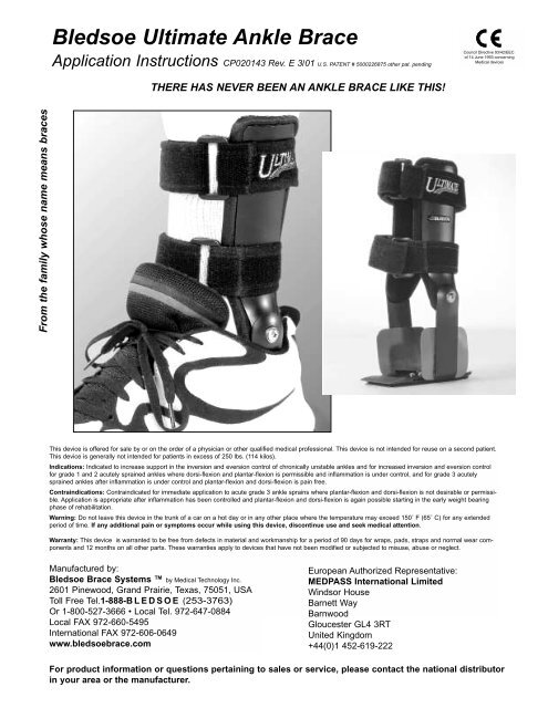
From the family whose name means braces<br />
<strong>Bledsoe</strong> <strong>Ultimate</strong> <strong>Ankle</strong> <strong>Brace</strong><br />
<strong>Application</strong> <strong>Instructions</strong> CP020143 Rev. E 3/01 U.S. PATENT # 5000226875 other pat. pending<br />
THERE HAS NEVER BEEN AN ANKLE BRACE LIKE THIS!<br />
Council Directive 93/42/EEC<br />
of 14 June 1993 concerning<br />
Medical devices<br />
This device is offered for sale by or on the order of a physician or other qualified medical professional. This device is not intended for reuse on a second patient.<br />
This device is generally not intended for patients in excess of 250 lbs. (114 kilos).<br />
Indications: Indicated to increase support in the inversion and eversion control of chronically unstable ankles and for increased inversion and eversion control<br />
for grade 1 and 2 acutely sprained ankles where dorsi-flexion and plantar-flexion is permissible and inflammation is under control, and for grade 3 acutely<br />
sprained ankles after inflammation is under control and plantar-flexion and dorsi-flexion is pain free.<br />
Contraindications: Contraindicated for immediate application to acute grade 3 ankle sprains where plantar-flexion and dorsi-flexion is not desirable or permissible.<br />
<strong>Application</strong> is appropriate after inflammation has been controlled and plantar-flexion and dorsi-flexion is again possible starting in the early weight bearing<br />
phase of rehabilitation.<br />
Warning: Do not leave this device in the trunk of a car on a hot day or in any other place where the temperature may exceed 150˚ F (65˚ C) for any extended<br />
period of time. If any additional pain or symptoms occur while using this device, discontinue use and seek medical attention.<br />
Warranty: This device is warranted to be free from defects in material and workmanship for a period of 90 days for wraps, pads, straps and normal wear components<br />
and 12 months on all other parts. These warranties apply to devices that have not been modified or subjected to misuse, abuse or neglect.<br />
Manufactured by:<br />
<strong>Bledsoe</strong> <strong>Brace</strong> Systems by Medical Technology Inc.<br />
2601 Pinewood, Grand Prairie, Texas, 75051, USA<br />
Toll Free Tel.1-888-BLEDSOE (253-3763)<br />
Or 1-800-527-3666 • Local Tel. 972-647-0884<br />
Local FAX 972-660-5495<br />
International FAX 972-606-0649<br />
www.bledsoebrace.com<br />
European Authorized Representative:<br />
MEDPASS International Limited<br />
Windsor House<br />
Barnett Way<br />
Barnwood<br />
Gloucester GL4 3RT<br />
United Kingdom<br />
+44(0)1 452-619-222<br />
For product information or questions pertaining to sales or service, please contact the national distributor<br />
in your area or the manufacturer.
<strong>Bledsoe</strong> <strong>Ultimate</strong> <strong>Ankle</strong> <strong>Brace</strong> <strong>Application</strong> <strong>Instructions</strong><br />
<strong>Quick</strong>-<strong>Fit</strong><br />
Step 1. Temporarily remove the inner<br />
sole from the sport shoe. If the inner<br />
sole is attached with glue, carefully<br />
remove it and remove any remaining<br />
debris. Clean as necessary. If the inner<br />
sole is damaged, replace it with another<br />
one from any local drug or shoe<br />
store.<br />
Step 4. Slip the foot into the shoe and<br />
move the upright arms to a comfortable<br />
position. Tie the shoe in a normal<br />
manner.<br />
Page 2 of 15 CP020143 Rev. E 3/01<br />
Step 1 Step 2 Step 3<br />
Step 4<br />
Step 2. Pull the protective backing<br />
from the loop fastener piece and center<br />
it in heel area of shoe with an even<br />
perimeter spacing and with the outer<br />
edge parallel, with the outer edge of<br />
the shoe. The position is not very<br />
critical.<br />
Step 5<br />
Step 5. Grasp each arm and move the<br />
ankle brace back and forth as well as<br />
rotationally, until both plates are<br />
centered over the ankle bones. Be<br />
careful to feel the front and back edges<br />
of each plate to be certain each one is<br />
centered over its ankle bone.<br />
Step 3. Place the ankle brace into the<br />
shoe with the plastic quick-fit protector<br />
applied. Replace the inner sole over<br />
the brace. Unfasten the straps and<br />
remove each strap from one arm leaving<br />
the strap attached to the arm<br />
nearest the D-ring.<br />
Step 6<br />
Position the arms upright against the<br />
sides of the leg. Press in firmly on both<br />
upper plates while wrapping each strap<br />
around the leg. Attach the straps inner<br />
surface to the hook patch on the other<br />
plate. Pass the strap end through the<br />
D-ring and tension comfortably, then<br />
fasten the end. Move the foot and<br />
ankle in all directions to be certain<br />
there are no point pressures.<br />
(see next page)
<strong>Bledsoe</strong> <strong>Ultimate</strong> <strong>Ankle</strong> <strong>Brace</strong> <strong>Application</strong> <strong>Instructions</strong><br />
<strong>Quick</strong>-<strong>Fit</strong><br />
Step 6a. It is recommended that you<br />
walk around the room and move the<br />
ankle into every possible position, to<br />
be absolutely certain there are no point<br />
pressures. When the brace is in a<br />
comfortable position, grasp the outer<br />
tab and peel it loose from the arm, then<br />
tear off the upper tab piece at the<br />
scored area by pulling to the back or<br />
front of the brace.<br />
Step 6b. Peel loose the upper tab on<br />
the inner side of the brace, then carefully<br />
pull out the quick-fit applicator.<br />
Step down on the brace to engage the<br />
fastener strip. The brace is now ready!<br />
To refit in another shoe, reattach the<br />
plastic film to the brace with tape. If<br />
any discomfort or pressure is present,<br />
it may be necessary to refit<br />
using the standard application<br />
instructions.<br />
Page 3 of 15 CP020143 Rev. E 3/01
<strong>Bledsoe</strong> <strong>Ultimate</strong> <strong>Ankle</strong> <strong>Brace</strong> <strong>Application</strong> <strong>Instructions</strong><br />
(Alternate fitting method without quick fit)<br />
2. Test fit the <strong>Ultimate</strong> <strong>Ankle</strong> <strong>Brace</strong> into the shoe to be certain it will fit before<br />
removing the inner sole.<br />
Page 4 of 15 CP020143 Rev. E 3/01<br />
Step 1<br />
Step 3<br />
1. Place foot in the shoe. Position a small piece of tape at the top edge of<br />
both sides of the shoe just below each ankle bone (malleolus). Mark the<br />
center position (see arrow) of each ankle bone with a vertical line on the tape<br />
for later help in positioning the ankle brace. Note: After inserting the brace,<br />
these marks will usually be 1/8”-3/16” (3cm-5cm) farther back due to the<br />
slightly increased width of the brace in the shoe.<br />
Step 2<br />
3. Carefully remove the inner sole from the inside of the shoe. Remove any<br />
remaining inner sole material and debris. Clean the inner lower surface<br />
where the inner sole was previously placed using rubbing alcohol or other<br />
appropriate cleaner. The shoe must be clean and dry before applying the<br />
loop pile fastening strip to the shoe.<br />
Note: Replacement inner soles are available at most shoe stores or drug<br />
stores.
<strong>Bledsoe</strong> <strong>Ultimate</strong> <strong>Ankle</strong> <strong>Brace</strong> <strong>Application</strong> <strong>Instructions</strong><br />
Step 4<br />
5. Loosen the straps from the D-rings, disengage each strap from the hook<br />
fastener on one curved plate so that each strap is only attached to the<br />
curved plate nearest to the D-ring. Be certain to refasten the hook end back<br />
to the strap surface to prevent entanglement.<br />
Step 6<br />
4. Test fit the loop pile fastening strip inside the shoe before removing the<br />
protective backing from the adhesive. Center the strip from side to side in the<br />
shoe with an even perimeter space around the edges of the strip at the heel<br />
area. Once certain of the position, remove the protective backing from the<br />
adhesive and place the strip into place. Press firmly to engage the adhesive.<br />
Step 5<br />
6. Using the #2 Phillips head screwdriver provided, loosen 1/2 turn on each<br />
of the four Phillips truss screws on the footplate. This permits the lower<br />
arms of the brace to be adjusted for width and position.<br />
Page 5 of 15 CP020143 Rev. E 3/01
<strong>Bledsoe</strong> <strong>Ultimate</strong> <strong>Ankle</strong> <strong>Brace</strong> <strong>Application</strong> <strong>Instructions</strong><br />
8. Beginning with the arm for the outer ankle bone (lateral malleolus), push<br />
the arm outward until the plastic plate and arm are in contact with the side<br />
of the shoe. Then slide the arm along the inner side surface of the shoe until<br />
the center of the hinge screw is in alignment with or slightly in front of the<br />
mark on the tape which represents the approximate position of the outer<br />
ankle bone (lateral malleolus). Press the arm outward firmly against the<br />
shoe side while maintaining this alignment, and snug the two phillips head<br />
screws at the back of the slot on the footplate to prevent movement. Now<br />
repeat the same procedure for the other arm for the inner ankle bone<br />
(medial malleolus). Be certain the arms are in firm contact with the sides of<br />
the shoe and that the center hinge screws for both hinges are aligned<br />
slightly forward of the marks on the tape strips. Tighten all four Phillips head<br />
screws firmly but do not overtorque.<br />
Page 6 of 15 CP020143 Rev. E 3/01<br />
Step 7<br />
Step 9<br />
7. Position the <strong>Brace</strong> into the shoe with the footplate evenly spaced from side<br />
to side and an even perimeter space between the footplate and the shoe at<br />
the heel area. Press firmly into position to engage the hook and loop pile<br />
fastener.<br />
9a. Replace the inner sole in the shoe over the footplate.<br />
Step 8<br />
9b.Test fit by slipping the foot into the shoe while the ankle brace curved<br />
plates are folded rearwards. Do Not Spread the Arms To <strong>Fit</strong> the Foot!<br />
Fasten the shoe strings. Check the position of the pivot points to be certain<br />
they are in alignment with the ankle bone. If not, readjust the lower arms<br />
until they are vertically aligned with the ankle bones. Remove the tape<br />
strips.
<strong>Bledsoe</strong> <strong>Ultimate</strong> <strong>Ankle</strong> <strong>Brace</strong> <strong>Application</strong> <strong>Instructions</strong><br />
Step 10<br />
11. Check the position of the hinges and test for any pressure points on the<br />
ankle bones when turning, pivoting, twisting, walking, or running. If<br />
necessary, readjust the position of the hinges to eliminate any point<br />
pressure. If pressure points cannot be eliminated, check to be certain<br />
the center pivot point for each hinge is slightly higher than the ankle<br />
bones. If not, it is necessary to obtain the proper size.<br />
Do not use this device if excess pressure points are present!<br />
Step 12<br />
10. Swing the curved plates into position on the sides of the leg. Unfasten the<br />
hook end of the strap and wrap it around the leg to the opposite side with one<br />
hand while firmly holding and squeezing both curved plates against the sides<br />
of the leg. Wrap the strap over the hook patch on the opposite curved plate to<br />
engage the hook fastener to the inner loop pile surface of the strap. Pass the<br />
strap end through the D-ring, pull back, tension the strap comfortably and<br />
fasten the hook to the strap surface.<br />
12. The <strong>Bledsoe</strong> ULTIMATE <strong>Ankle</strong> <strong>Brace</strong> is now ready for use. Always<br />
inspect for loose, damaged, or worn parts before each use. If any<br />
discrepancy is noted, repair or replace the parts before use.<br />
Step 11<br />
Page 7 of 15 CP020143 Rev. E 3/01
SPECIAL INSTRUCTIONS FOR ORTHOTISTS<br />
This device may be custom formed by a trained Orthotist using certain precautions. The Aluminum Alloy is 7075-T6<br />
and is extremely stiff and springy. Do not attempt to bend or further form any portions of the soleplate or the formed<br />
upper plates. The lower medial and lateral upright arms may be formed by using smooth curves over a round<br />
mandrel of not less than 1" (2.54cm) in diameter. Protect the bent angle at the bottom of each arm and do not<br />
change the bend in this area.<br />
LUBRICATION & DISASSEMBLY INSTRUCTIONS<br />
The <strong>Bledsoe</strong> ULTIMATE <strong>Ankle</strong> <strong>Brace</strong> can be disassembled to permit cleaning or replacement of parts. The hinges<br />
contain NYLATRON self-lubricating spacers for smooth operation which can be replaced. The hinge should be<br />
cleaned and relubricated frequently if exposed to dirt, sand, or other hostile elements. Use the tube of hinge lubricant<br />
provided (or a good quality bearing grease) to relubricate the center pivot bushings of each hinge. Be certain to<br />
place one drop of the resettable thread-locking adhesive (can be obtained from <strong>Bledsoe</strong>) on the threads at the side<br />
of the tip of each screw before reassembling. Allow at least 30 minutes after assembly for the thread-locking adhesive<br />
to cure before using the brace. Do not use any other type of thread-locking adhesive or it may be impossible to<br />
remove the screws later. The sizes of the footplate and the lower arms are marked on each part. When ordering<br />
replacement parts, please state the size and left or right.<br />
HINGE DISASSEMBLY<br />
The outer curved plate and lower arm are different from the inner curved plate and lower arm.The outer curved plate<br />
is symmetrical while the inner plate is not symmetrical. The bend in the outer lower arm is constant radius while the<br />
inner lower arm is a cone shaped bend. If uncertain of their positions, mark them before removal.<br />
Remove the Phillips truss head screw from the hinge center while holding the curved plate. Be careful to note the<br />
Stainless Steel washer and small NYLATRON washer just beneath the screw head. The pivot bushing is<br />
permanently attached to the curved upper plate. If excessive wear is present on the bushing, replace the plate<br />
assembly. If excessive wear is present in the pivot hole, replace the lower arm. Clean the bushing, hole, and NYLA-<br />
TRON washers with ordinary dishwashing detergent or soap. Place the large NYLATRON washer over the bushing<br />
on the curved plate. Apply a small amount of hinge lubricant to the pivot bushing, then slip the pivot bushing through<br />
the hole in the lower arm from the inside.<br />
Note that the Stainless Steel washer has a flat spot on it’s inner hole. This flat area is to be aligned with the flat area<br />
on the end of the pivot bushing. Place the small NYLATRON washer on the pivot bushing first followed by the Stainless<br />
Steel washer being careful to align the flats. Now place one drop of thread-locking adhesive on the threads of<br />
the Phillips truss head screw at the side of the tip. Thread the screw in by hand before using a screwdriver to prevent<br />
stripping of the threads. Tighten the screw firmly with a #2 Phillips screwdriver being careful not to permit the<br />
washers to come off of the flat part of the bushing. Allow at least 30 minutes for the thread-locking adhesive to cure<br />
before use.<br />
Page 8 of 15 CP020143 Rev. E 3/01
FOOTPLATE REPLACEMENT<br />
The footplate is replaceable as an assembly. Please state the footplate size and left or right when ordering.<br />
The adhesive backed hook fastener strip is already applied at the factory on the new footplate. Remove<br />
the four Phillips truss head screws from the upper surface of the footplate and remove the four nuts from<br />
the slot at the bottom of the footplate. Replace the arms in the new footplate and refit the screws and nuts.<br />
The nuts should align themselves in the slot on the lower surface of the footplate. Readjust the position of<br />
the arms by following the original application instructions.<br />
LOWER ARM & PLASTIC PROTECTOR PLATE REPLACEMENT<br />
The lower arms each have a plastic protector plate attached with peel-and-stick adhesive on their inner<br />
lower surface. To replace these plates, first obtain the new plates with adhesive backed strips from <strong>Bledsoe</strong><br />
<strong>Brace</strong> Systems. The plates are universal in size. Carefully remove the old plates and clean the old adhesive<br />
from the arms with a suitable adhesive remover solvent obtainable from any Automotive Parts Store.<br />
Do not apply solvent to the plastic plates. Test fit the plates then remove the adhesive backing and place<br />
the plates at the lower edge of the inner arm surface with the cut out notch of the plate just above the<br />
curve. Do not place the plates too low on the curved or bent area. The plate must be affixed to the flat portion<br />
of the inner surface of the lower arm.<br />
The lower arms may be replaced and are sized. They are left and right as well as outer (lateral) and inner<br />
(medial) and are available in different height ranges. First obtain the numbers on the old arms or state the<br />
size, part number of the old brace, as well as left or right when ordering. Remove the lower arms from the<br />
footplate as stated above under footplate replacement. Then remove the upper curved plates as stated in<br />
the hinge disassembly instructions. Replace the lower arms and plastic protector plates as stated in the<br />
above sections, then readjust the brace as stated in the original application instructions.<br />
MATERIALS/COMPATIBILITY<br />
The <strong>Bledsoe</strong> ULTIMATE <strong>Ankle</strong> <strong>Brace</strong> is constructed of black anodized 7075-T6 Aluminum Alloy with pads<br />
made from Polyester/Nylon fabric surface heat bonded to cross-linked polyethylene foam. The screws and<br />
nuts are Stainless Steel, while the bushings are 416C heat treated Stainless Steel. The wear washers are<br />
Graphite impregnated Nylon called NYLATRON. The straps are composed of woven Nylon loop pile fabric<br />
with molded or woven Nylon hook material. The D-rings are made from Delrin (Acetal) plastic. The hinge<br />
lubricant is a standard Lithium based wheel bearing grease. All components are made in Texas. The materials<br />
are well known and widely used for such devices. No known hazardous or allergic materials are utilized.<br />
Page 9 of 15 CP020143 Rev. E 3/01
REPLACEMENT PARTS (EXPLODED VIEW)<br />
UPPER CURVED PLATE<br />
ASSEMBLIES W/BUSHING<br />
W/HOOK PATCH<br />
AS002320 (OUTER)<br />
NYLATRON<br />
WASHER, LARGE<br />
AS001005<br />
NYLATRON<br />
WASHER<br />
AS001001<br />
STAINLESS<br />
STEEL WASHER<br />
AS001002<br />
HINGE SCREWS<br />
#10-32<br />
TRUSS HEAD<br />
CH040037<br />
LOWER ARMS, OUTER (LATERAL)<br />
AS001150-AS001159 (10 SIZE LEFT)<br />
AS001250-AS001259 (10 SIZE RIGHT)<br />
Page 10 of 15 CP020143 Rev. E 3/01<br />
OUTER PAD<br />
(LATERAL)<br />
W/ADHESIVE<br />
OUTER<br />
LOWER PAD<br />
W/ADHESIVE<br />
FOOTPLATE ASSEMBLY<br />
AS008101-AS008109 (5 SIZE LEFT)<br />
AS008201-AS008209 (5 SIZE RIGHT)<br />
HOOK FASTENER FOR FOOTPLATE<br />
AS011101-AS011109 (5 SIZE LEFT)<br />
AS011201-AS011209 (5 SIZE RIGHT)<br />
LOOP FASTENER FOR SHOE<br />
AS012101-AS012109 (5 SIZE LEFT)<br />
AS012201-AS012209 (5 SIZE RIGHT)<br />
STRAP KIT, 2 STRAPS<br />
AS010002<br />
PAD KIT, LEFT/RIGHT<br />
AS010100/AS010200<br />
INNER PAD<br />
(LATERAL)<br />
LEFT/RIGHT<br />
W/ADHESIVE<br />
LOWER ARM PLASTIC PROTECTOR<br />
PLATES W/ADHESIVE<br />
AS006010<br />
UPPER CURVED PLATE<br />
ASSEMBLIES W/BUSHING<br />
W/HOOK PATCH<br />
AS002120 (INNER LEFT)<br />
AS002220 (INNER RIGHT)<br />
NYLATRON<br />
WASHER, LARGE<br />
AS001005<br />
NYLATRON<br />
WASHER<br />
AS001001<br />
STAINLESS<br />
STEEL WASHER<br />
AS001002<br />
HINGE SCREWS<br />
#10-32, TRUSS HEAD<br />
CH040037<br />
LOWER ARMS, INNER (MEDIAL)<br />
AS001100-AS001109 (10 SIZE LEFT)<br />
AS001200-AS001209 (10 SIZE RIGHT)<br />
4 X #6-32 PHILLIPS<br />
TRUSS HEAD SCREW<br />
CH040038<br />
4 X #6-32 SELF<br />
LOCKING NUT<br />
CH070031<br />
HINGE LIBRICANT<br />
BK001500--<br />
THREAD LOCK<br />
DA010126
STRAP KIT<br />
Universal AS010002 2 straps<br />
REPLACEMENT PARTS LIST<br />
PAD KIT<br />
Left AS010100 includes all necessary pads, with adhesive backing<br />
Right AS010200 includes all necessary pads, with adhesive backing<br />
UPPER PLATE<br />
Left Inner AS002120 with bushing and hook patches<br />
Right Inner AS002220 with bushing and hook patches<br />
Universal Outer AS002320 with bushing and hook patches<br />
LOWER INNER ARMS (medial) LOWER OUTER ARMS (lateral)<br />
00L Left AS001100 50L Left AS001150<br />
01L Left AS001101 51L Left AS001151<br />
02L Left AS001102 52L Left AS001152<br />
03L Left AS001103 53L Left AS001153<br />
04L Left AS001104 54L Left AS001154<br />
05L Left AS001105 55L Left AS001155<br />
06L Left AS001106 56L Left AS001156<br />
07L Left AS001107 57L Left AS001157<br />
08L Left AS001108 58L Left AS001158<br />
09L Left AS001109 59L Left AS001159<br />
00R Right AS001200 50R Right AS001250<br />
01R Right AS001201 51R Right AS001251<br />
02R Right AS001202 52R Right AS001252<br />
03R Right AS001203 53R Right AS001253<br />
04R Right AS001204 54R Right AS001254<br />
05R Right AS001205 55R Right AS001255<br />
06R Right AS001206 56R Right AS001256<br />
07R Right AS001207 57R Right AS001257<br />
08R Right AS001208 58R Right AS001258<br />
09R Right AS001209 59R Right AS001259<br />
FOOTPLATE ASSEMBLY<br />
Extra Small Left AS008101<br />
Small Left AS008103<br />
Medium Left AS008105<br />
Large Left AS008107<br />
Extra Large Left AS008109<br />
Extra Small Right AS008201<br />
Small Right AS008203<br />
Medium Right AS008205<br />
Large Right AS008207<br />
Extra Large Right AS008209<br />
Page 11 of 15 CP020143 Rev. E 3/01
LOWER ARM PROTECTOR PLATE<br />
Standard AS006010 for 02 - 09 and 50 - 59 lower arms<br />
Extra small AS006011 for 00, 01, 50 and 51 lower arms<br />
ANKLE HINGE REFURBISHING KIT<br />
Full Set AS010007 Includes: (lubricant, threadlock, screws, washers)<br />
LOWER ARM ADJUSTMENT SCREW KIT<br />
Universal AS010003 Includes: (screws, nuts)<br />
HOOK FASTENER FOR FOOTPLATE<br />
Extra Small Left AS011101<br />
Small Left AS011103<br />
Medium Left AS011105<br />
Large Left AS011107<br />
Extra Large Left AS011109<br />
Extra Small Right AS011201<br />
Small Right AS011203<br />
Medium Right AS011205<br />
Large Right AS011207<br />
Extra Large Right AS011209<br />
PILE FASTENER FOR SHOE<br />
Extra Small Left AS012101<br />
Small Left AS012103<br />
Medium Left AS012105<br />
Large Left AS012107<br />
Extra Large Left AS012109<br />
Extra Small Right AS012201<br />
Small Right AS012203<br />
Medium Right AS012205<br />
Large Right AS012207<br />
Extra Large Right AS012209<br />
HINGE LUBRICANT BK001500<br />
THREAD LOCK DA010126<br />
INSTRUCTION SHEET CP020143<br />
MEASURING CARD<br />
In Inches CP010107<br />
Page 12 of 15 CP020143 Rev. E 3/01
Cut on dotted Line<br />
Page 13 of 15 CP020143 Rev. E 3/01
Page 14 of 15 CP020143 Rev. E 3/01
NOTE:<br />
ADDING AN ADDITIONAL PAD TO THE MEDIAL PLASTIC PROTECTOR PLATE IS<br />
RECOMMENDED IF PATIENT HAS;<br />
• LOWER THAN NORMAL ARCH<br />
• MODERATE TO EXTREME EVERSION<br />
• VALGUS POSITIONING OF THE ANKLE<br />
TO APPLY:<br />
1. PEEL PROTECTIVE BACKING<br />
FROM ADHESIVE ON BACKSIDE<br />
OF PAD<br />
2. APPLY PAD TO MEDIAL PLATE<br />
WITH THINNER EDGE OF PAD<br />
ALIGNED WITH THE TOP OF THE<br />
PLASTIC PLATE AS SHOWN<br />
Page 15 of 15 CP020143 Rev. E 3/01

