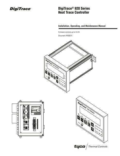
DigiTrace® 920 Series Heat Trace Controller - California Detection ...
DigiTrace® 920 Series Heat Trace Controller - California Detection ...
DigiTrace® 920 Series Heat Trace Controller - California Detection ...

Create successful ePaper yourself
Turn your PDF publications into a flip-book with our unique Google optimized e-Paper software.
Digi<strong>Trace</strong> <strong>920</strong> SERIES<br />
A<br />
B<br />
ALARM MONITOR CONFIG<br />
SHIFT A/B<br />
BACK ENTER<br />
LOCK<br />
® Digi<strong>Trace</strong><br />
<strong>920</strong> <strong>Series</strong><br />
<strong>Heat</strong> <strong>Trace</strong> <strong>Controller</strong><br />
Installation, Operating, and Maintenance Manual<br />
Firmware versions up to V3.2X<br />
Document #H56874<br />
PROGRAMMABLE DUAL POINT<br />
HEAT TRACING CONTROLLER<br />
STATUS<br />
ALARM<br />
OUTPUT<br />
Tx<br />
Rx<br />
Digi<strong>Trace</strong> <strong>920</strong> SERIES<br />
ALARM MONITOR CONFIG<br />
SHIFT A/B<br />
BACK ENTER<br />
LOCK<br />
STATUS<br />
ALARM<br />
OUTPUT
Table of Contents<br />
Introduction . . . . . . . . . . . . . . . . . . . . . . . . . . . . . . . . . . . . . . . . . . . . . . . . . . . . . . 5<br />
Certification . . . . . . . . . . . . . . . . . . . . . . . . . . . . . . . . . . . . . . . . . . . . . . . . . . . . . . . . . . . . . . 5<br />
Limited Warranty . . . . . . . . . . . . . . . . . . . . . . . . . . . . . . . . . . . . . . . . . . . . . . . . . . . . . . . . . . 5<br />
Warranty Exclusion/Disclaimer . . . . . . . . . . . . . . . . . . . . . . . . . . . . . . . . . . . . . . . . . . . . . . . 5<br />
Exclusive Remedies . . . . . . . . . . . . . . . . . . . . . . . . . . . . . . . . . . . . . . . . . . . . . . . . . . . . . . . . 5<br />
Conducted and Radiated Emissions—FCC/DOC Statement of Compliance . . . . . . . . . . . . . . 5<br />
What’s New . . . . . . . . . . . . . . . . . . . . . . . . . . . . . . . . . . . . . . . . . . . . . . . . . . . . . . 6<br />
New <strong>Controller</strong> Features. . . . . . . . . . . . . . . . . . . . . . . . . . . . . . . . . . . . . . . . . . . . . . . . . . . . . 6<br />
New Operator Console Features. . . . . . . . . . . . . . . . . . . . . . . . . . . . . . . . . . . . . . . . . . . . . . . 7<br />
Section 1 Overview. . . . . . . . . . . . . . . . . . . . . . . . . . . . . . . . . . . . . . . . . . . . . . . . . 7<br />
1.1 <strong>Controller</strong>s Covered by this Manual . . . . . . . . . . . . . . . . . . . . . . . . . . . . . . . . . . . . . . . . . . 7<br />
1.2 Product Overview . . . . . . . . . . . . . . . . . . . . . . . . . . . . . . . . . . . . . . . . . . . . . . . . . . . . . . . . 7<br />
1.3 Modular Components . . . . . . . . . . . . . . . . . . . . . . . . . . . . . . . . . . . . . . . . . . . . . . . . . . . . .9<br />
1.4 <strong>Controller</strong> Assemblies. . . . . . . . . . . . . . . . . . . . . . . . . . . . . . . . . . . . . . . . . . . . . . . . . . . .10<br />
1.5 Ordering and Configuration Guide . . . . . . . . . . . . . . . . . . . . . . . . . . . . . . . . . . . . . . . . . . 10<br />
Section 2 Installation and Wiring . . . . . . . . . . . . . . . . . . . . . . . . . . . . . . . . . . . . . . 12<br />
2.1 Introduction . . . . . . . . . . . . . . . . . . . . . . . . . . . . . . . . . . . . . . . . . . . . . . . . . . . . . . . . . . . 12<br />
2.2 Initial Inspection . . . . . . . . . . . . . . . . . . . . . . . . . . . . . . . . . . . . . . . . . . . . . . . . . . . . . . . . 12<br />
2.3 Operator Safety Considerations . . . . . . . . . . . . . . . . . . . . . . . . . . . . . . . . . . . . . . . . . . . . 12<br />
2.4 Operating Environment . . . . . . . . . . . . . . . . . . . . . . . . . . . . . . . . . . . . . . . . . . . . . . . . . . . 12<br />
2.5 Installation Location . . . . . . . . . . . . . . . . . . . . . . . . . . . . . . . . . . . . . . . . . . . . . . . . . . . . . 12<br />
2.6 Mounting Procedures . . . . . . . . . . . . . . . . . . . . . . . . . . . . . . . . . . . . . . . . . . . . . . . . . . . . 13<br />
2.7 Wiring. . . . . . . . . . . . . . . . . . . . . . . . . . . . . . . . . . . . . . . . . . . . . . . . . . . . . . . . . . . . . . . . 14<br />
2.8 Initial Power-up . . . . . . . . . . . . . . . . . . . . . . . . . . . . . . . . . . . . . . . . . . . . . . . . . . . . . . . . 17<br />
2.9 Setup for the <strong>920</strong> . . . . . . . . . . . . . . . . . . . . . . . . . . . . . . . . . . . . . . . . . . . . . . . . . . . . . . . 18<br />
Section 3 Programming and Configuration . . . . . . . . . . . . . . . . . . . . . . . . . . . . . . . . 18<br />
3.1 Introduction . . . . . . . . . . . . . . . . . . . . . . . . . . . . . . . . . . . . . . . . . . . . . . . . . . . . . . . . . . . 18<br />
3.2 Front Panel Features . . . . . . . . . . . . . . . . . . . . . . . . . . . . . . . . . . . . . . . . . . . . . . . . . . . . . 19<br />
3.3 <strong>920</strong> Operator Console Display . . . . . . . . . . . . . . . . . . . . . . . . . . . . . . . . . . . . . . . . . . . . . 19<br />
3.4 <strong>920</strong> Functions. . . . . . . . . . . . . . . . . . . . . . . . . . . . . . . . . . . . . . . . . . . . . . . . . . . . . . . . . . 20<br />
3.5 Control Point Setup . . . . . . . . . . . . . . . . . . . . . . . . . . . . . . . . . . . . . . . . . . . . . . . . . . . . . 20<br />
3.6 Common <strong>Controller</strong> Setup . . . . . . . . . . . . . . . . . . . . . . . . . . . . . . . . . . . . . . . . . . . . . . . . 29<br />
3.7 Temperature Alarms . . . . . . . . . . . . . . . . . . . . . . . . . . . . . . . . . . . . . . . . . . . . . . . . . . . . .32<br />
3.8 Other Alarms. . . . . . . . . . . . . . . . . . . . . . . . . . . . . . . . . . . . . . . . . . . . . . . . . . . . . . . . . . . 34<br />
3.9 Communications Setup. . . . . . . . . . . . . . . . . . . . . . . . . . . . . . . . . . . . . . . . . . . . . . . . . . . 42<br />
3.10 Operator Console Functions . . . . . . . . . . . . . . . . . . . . . . . . . . . . . . . . . . . . . . . . . . . . . . 45<br />
3.11 Copy Configuration Functions (V3.11 and up) . . . . . . . . . . . . . . . . . . . . . . . . . . . . . . . . 46<br />
Section 4 Monitored Parameters . . . . . . . . . . . . . . . . . . . . . . . . . . . . . . . . . . . . . . 47<br />
4.1 Introduction . . . . . . . . . . . . . . . . . . . . . . . . . . . . . . . . . . . . . . . . . . . . . . . . . . . . . . . . . . . 47<br />
4.2 Analog Readings. . . . . . . . . . . . . . . . . . . . . . . . . . . . . . . . . . . . . . . . . . . . . . . . . . . . . . . . 47<br />
4.3 Maintenance Data . . . . . . . . . . . . . . . . . . . . . . . . . . . . . . . . . . . . . . . . . . . . . . . . . . . . . . . 49<br />
Section 5 Control Modes . . . . . . . . . . . . . . . . . . . . . . . . . . . . . . . . . . . . . . . . . . . . 50<br />
5.1 Introduction . . . . . . . . . . . . . . . . . . . . . . . . . . . . . . . . . . . . . . . . . . . . . . . . . . . . . . . . . . . 50<br />
5.2 Switch Control Modes . . . . . . . . . . . . . . . . . . . . . . . . . . . . . . . . . . . . . . . . . . . . . . . . . . . 50<br />
5.3 Load Shedding Control Mode . . . . . . . . . . . . . . . . . . . . . . . . . . . . . . . . . . . . . . . . . . . . . . 52<br />
5.4 TEMPBUS Control Mode . . . . . . . . . . . . . . . . . . . . . . . . . . . . . . . . . . . . . . . . . . . . . . . . 53<br />
Section 6 Troubleshooting . . . . . . . . . . . . . . . . . . . . . . . . . . . . . . . . . . . . . . . . . . . 55<br />
6.1 Operator Checks . . . . . . . . . . . . . . . . . . . . . . . . . . . . . . . . . . . . . . . . . . . . . . . . . . . . . . . . 55<br />
6.2 Common Problem Areas. . . . . . . . . . . . . . . . . . . . . . . . . . . . . . . . . . . . . . . . . . . . . . . . . . 55<br />
6.3 Common Alarms—What to look for . . . . . . . . . . . . . . . . . . . . . . . . . . . . . . . . . . . . . . . . . 58<br />
Section 7 Maintenance . . . . . . . . . . . . . . . . . . . . . . . . . . . . . . . . . . . . . . . . . . . . . 60<br />
7.1 Operator Maintenance. . . . . . . . . . . . . . . . . . . . . . . . . . . . . . . . . . . . . . . . . . . . . . . . . . . .60<br />
7.2 Replaceable Parts . . . . . . . . . . . . . . . . . . . . . . . . . . . . . . . . . . . . . . . . . . . . . . . . . . . . . . . 60<br />
Appendix A Specifications . . . . . . . . . . . . . . . . . . . . . . . . . . . . . . . . . . . . . . . . . . . 61<br />
Appendix B Typical Enclosure Dimensions . . . . . . . . . . . . . . . . . . . . . . . . . . . . . . . . 63<br />
B.1 Single-Point Assemblies #10160-003 and #10160-009 . . . . . . . . . . . . . . . . . . . . . . . . . 63<br />
B.2 Dual-Point Assemblies #10160-120 and #10160-121 . . . . . . . . . . . . . . . . . . . . . . . . . . . 64<br />
3
4<br />
B.3 Four-Point Assembly #10160-125 . . . . . . . . . . . . . . . . . . . . . . . . . . . . . . . . . . . . . . . . . . 65<br />
B.4 Eight-Point Assembly #10160-035 . . . . . . . . . . . . . . . . . . . . . . . . . . . . . . . . . . . . . . . . . 66<br />
B.5 Twenty-Point Assembly #10160-045 . . . . . . . . . . . . . . . . . . . . . . . . . . . . . . . . . . . . . . . . 67<br />
Appendix C Wiring Diagrams . . . . . . . . . . . . . . . . . . . . . . . . . . . . . . . . . . . . . . . . . 68<br />
C.1 TS Wiring . . . . . . . . . . . . . . . . . . . . . . . . . . . . . . . . . . . . . . . . . . . . . . . . . . . . . . . . . . . . 68<br />
C.2 Power Wiring . . . . . . . . . . . . . . . . . . . . . . . . . . . . . . . . . . . . . . . . . . . . . . . . . . . . . . . . . . 70<br />
C.3 Communication Wiring . . . . . . . . . . . . . . . . . . . . . . . . . . . . . . . . . . . . . . . . . . . . . . . . . . 71<br />
C.4 Alarm Output Wiring . . . . . . . . . . . . . . . . . . . . . . . . . . . . . . . . . . . . . . . . . . . . . . . . . . . .71<br />
C.5 External Input/Output Port Wiring . . . . . . . . . . . . . . . . . . . . . . . . . . . . . . . . . . . . . . . . . . 73<br />
Appendix D HTC Load Shedding Sequence. . . . . . . . . . . . . . . . . . . . . . . . . . . . . . . . 74<br />
Appendix E 100 Ω Platinum RTD Table . . . . . . . . . . . . . . . . . . . . . . . . . . . . . . . . . . 75<br />
Appendix F 100 Ω Nickel-Iron RTD Table. . . . . . . . . . . . . . . . . . . . . . . . . . . . . . . . . 76<br />
Appendix G Factory Default/Configuration Sheets . . . . . . . . . . . . . . . . . . . . . . . . . . . 77<br />
G.1 Configuration Sheet V3.00 . . . . . . . . . . . . . . . . . . . . . . . . . . . . . . . . . . . . . . . . . . . . . . . 77<br />
G.2 <strong>920</strong> <strong>Series</strong> HTC Configuration Sheet V3.1X . . . . . . . . . . . . . . . . . . . . . . . . . . . . . . . . . . . 80
Introduction<br />
Certification<br />
Limited Warranty<br />
Warranty Exclusion/Disclaimer<br />
Exclusive Remedies<br />
Conducted and Radiated Emissions—FCC/DOC Statement of Compliance<br />
Installation and Maintenance Instructions for Firmware Versions up to and Including V3.2X<br />
This manual provides information pertaining to the installation, operation, testing, adjustment,<br />
and maintenance of the <strong>Digi<strong>Trace</strong>®</strong><br />
Model <strong>920</strong> <strong>Series</strong> <strong>Heat</strong> <strong>Trace</strong> Control and Monitoring products.<br />
Additional copies of the operating manual may be ordered separately through your Tyco Thermal<br />
Controls representative or online at www.tycothermal.com using the document number H56874.<br />
Notice: The information contained in this document is subject to change without notice.<br />
Tyco Thermal Controls certifies that this product met its published specifications at the time of<br />
shipment from the Factory.<br />
This Tyco Thermal Controls product is warranted against defects in material and workmanship<br />
for a period of 18 months from the date of installation or 24 months from the date of purchase,<br />
whichever occurs first. During the warranty period, Tyco Thermal Controls will, at its option,<br />
either repair or replace products that prove to be defective.<br />
For warranty service or repair, this product must be returned to a service facility designated by<br />
Tyco Thermal Controls. The Buyer shall prepay shipping charges to Tyco Thermal Controls and<br />
Tyco Thermal Controls shall pay shipping charges to return the product to the Buyer. However,<br />
the Buyer shall pay all shipping charges, duties, and taxes for products returned to Tyco Thermal<br />
Controls from another country.<br />
Tyco Thermal Controls warrants that the software and firmware designated by Tyco Thermal<br />
Controls for use with the Digi<strong>Trace</strong> <strong>920</strong> <strong>Controller</strong> will execute its programming instructions<br />
properly. Tyco Thermal Controls does not warrant that the operation of the hardware, or software,<br />
or firmware will be uninterrupted or error-free<br />
The foregoing warranty shall not apply to defects resulting from improper or inadequate maintenance<br />
by the Buyer, Buyer-supplied software or interfacing, unauthorized modification or misuse,<br />
operation outside of the specifications for the product, or improper installation.<br />
No other warranty is expressed or implied. Tyco Thermal Controls disclaims the implied warranties<br />
of merchantability and fitness for a particular purpose.<br />
The remedies provided herein are the buyer’s sole and exclusive remedies. Tyco Thermal<br />
Controls shall not be liable for any direct, indirect, special, incidental, or consequential damages,<br />
whether based on contract, tort, or any other legal theory.<br />
This equipment has been tested and found to comply with the limits for a Class A digital device,<br />
pursuant to Part 15 of the FCC rules. These limits are designed to provide reasonable protection<br />
against harmful interference when the equipment is operated in a commercial environment. This<br />
equipment generates, uses, and can radiate radio frequency energy and, if not installed and used<br />
5
What’s New<br />
New <strong>Controller</strong> Features<br />
6<br />
in accordance with the instruction manual, may cause harmful interference to radio communications.<br />
Operation of this equipment in a residential area is likely to cause harmful interference, in<br />
which case the user will be required to correct the interference at his own expense.<br />
This equipment does not exceed Class A limits for radio emissions as set out in Schedule V to<br />
VIII of the Radio Interference Regulations of Communication Canada.<br />
Cet apparel respecte les limites de bruits radioelectriques applicables aux appareils numeriques<br />
de Classe A prescrites dans la norme sur le materiel brouilleur: “Appareils Numeriques,” NMB-<br />
003 edictee par le Ministre des Communications.<br />
This section provides a summary of the new features that have been added since the last version<br />
of this manual was printed. It is assumed that the reader is already familiar with the earlier versions<br />
of the <strong>920</strong> <strong>Controller</strong>.<br />
• Alarm filtering is now available for:<br />
– LOW and HIGH TS ALARMS (see sections 3.7.7 on page 33 and 3.7.8 on page 34)<br />
– LOW and HIGH CURRENT ALARMS (see sections 3.8.2 on page 35 and 3.8.4 on page 36)<br />
– HIGH GFI ALARMS (see section 3.8.6 on page 36)<br />
– LOW and HIGH VOLTAGE ALARMS (see sections 3.8.9 on page 37 and 3.8.11 on page 38)<br />
– LOW and HIGH RESISTANCE ALARMS (see sections 3.8.13 on page 38 and 3.8.15 on<br />
page 39).<br />
Alarm filtering will prevent an alarm from being indicated until the alarm condition has<br />
existed for the duration of the alarm filter time.<br />
• Two new SWITCH CONTROL MODES have been added for use with Ambient Temperature control:<br />
– Proportional Ambient SSR<br />
– Proportional Ambient Contactor (see sections 3.5.3 on page 21 and 5.2 on page 50).<br />
•<br />
ASCII and RTU ModBus communications protocol support (see section 3.9.1 on page 42).<br />
• Support for an isolated, 2-wire RS-485 communications interface (see section 1.4.5).<br />
• A 3-phase power calculation feature has been included for use with balanced, Y-connected<br />
heating loads (see section 3.5.10 on page 23).<br />
• A Temperature Sensor ( TS)<br />
Fail Mode feature is now available to allow the output to be forced<br />
ON or OFF when a control temperature failure occurs (see section 3.5.11 on page 23).<br />
• A TEMPBUS feature to allow one “master” <strong>920</strong> controller to share its temperature sensor<br />
information with up to 25 “slave” controllers (up to 50 control points). This includes the<br />
addition of three TS CONTROL MODES (see sections 3.5.12 on page 24 and 5.4 on page 53).<br />
• Support for 100 ohm nickel-iron RTDs along with the standard 100 ohm platinum types (see<br />
sections 3.5.13 on page 24 and 3.5.16 on page 25).<br />
• Manual voltage source selection (see section 3.5.19 on page 26).<br />
• Support for FORCE ON<br />
and FORCE OFF<br />
on page 28 and 3.6.3 on page 29).<br />
modes using the EXTERNAL input (see sections 3.5.27<br />
• Features to reload factory default parameters as well as copy configuration parameters from<br />
one point to another are now included (see section 3.11 on page 46).<br />
• New maintenance alarming to track contactor wear (see section 3.8.23 on page 42).
New Operator Console Features<br />
Section 1 Overview<br />
1.1 <strong>Controller</strong>s Covered by this Manual<br />
1.2 Product Overview<br />
• Monitor PEAK LOAD CURRENT,<br />
PEAK GFI,<br />
and the EXTERNAL INPUT STATUS through communications<br />
(see sections 4.3.6 on page 50, 4.3.7 on page 50, and 4.3.8 on page 50).<br />
• The ability to adjust the display scroll rate is now available (see section 3.6.10 on page 31).<br />
• Maintenance data resetting is now supported (see section 4.3 on page 49).<br />
• Display and reset the CONTACTOR CYCLE COUNTER (see section 4.3.3 on page 49).<br />
• Limit the range of the CONTROL SETPOINT setting for <strong>920</strong> Operator Console users<br />
(see sections 3.5.29 on page 29 and 3.5.30 on page 29).<br />
• An UNLOCK DATABASE feature was added to the <strong>920</strong> Operator Console’s “Configuration Mode<br />
Main Menu” (see section 3.10.3 on page 46).<br />
• The display test no longer occurs at startup; instead, the user may activate it from a menu<br />
option (see section 3.10.5 on page 46).<br />
This document covers the <strong>920</strong> <strong>Series</strong> of heat trace controllers and available options. The information<br />
coincides with the specific releases of firmware for the <strong>920</strong> product which are listed on<br />
the cover. As Tyco Thermal Controls releases new firmware to modify or enhance the product<br />
significantly, new documentation will accompany these releases. To ensure that you are using<br />
the correct documentation for your particular version of controller, please check the firmware<br />
version number of the <strong>920</strong> against the version number listed on the front of this manual. This<br />
can be displayed using the optional <strong>920</strong> Operator Console or a communicating device. As subsequent<br />
changes are made, supplements to this document will be included in manuals shipped<br />
after the firmware is released. Supplements will make specific reference to the operational or<br />
functional changes.<br />
1.2.1 DESCRIPTION<br />
The <strong>920</strong> <strong>Series</strong> <strong>Heat</strong>-Tracing <strong>Controller</strong> controls, monitors, and communicates alarms and data<br />
for one or two heating circuits. As a dual-point device, it offers a complete range of control and<br />
monitoring features, as well as superior reliability compared to multipoint systems. Its modular,<br />
scalable architecture yields cost-effective multipoint assemblies without the expense of additional<br />
control points that are not required. Available for use with external solid-state relays<br />
(SSRs) or contactors in either one-, two-, or three-pole configurations and the ability to switch<br />
loads up to 600 Vac makes the <strong>920</strong> the most versatile product on the market.<br />
1.2.2 FEATURES<br />
A detailed description of available features can be found in Section III of this manual. Highlights<br />
of specific features are included in the following text.<br />
Front Display<br />
The control module includes LED status indicators to show output and alarm conditions. Using<br />
the optional <strong>920</strong> Operator Console, the setpoint temperature, actual control temperature, and<br />
load current are immediately accessible to plant operators and maintenance staff. The display<br />
units are field selectable for °F or °C.<br />
7
8<br />
–40°F to 140°F (–40°C to 60°C) Operation<br />
Extended temperature operation permits installation in all but the harshest environments. SSR<br />
output modules are limited to operating ambient temperatures of 104°F (40°C) without derating.<br />
Single or Dual Temperature Sensor Inputs<br />
The ability to use one or two temperature sensor ( TS)<br />
inputs for each control point allows the<br />
selection of one of eleven control modes and programming of all temperature parameters.<br />
High and Low Temperature Alarms<br />
High and low temperature alarms are offered for both inputs of each control point.<br />
High and Low Current Alarms<br />
Low current alarm is more than just a continuity level alarm. The <strong>920</strong> offers full adjustment over<br />
the entire current measurement range for both high and low current alarm limits.<br />
Solid State or Contactor Output<br />
The <strong>920</strong> is available with externally-mounted solid-state relay ( SSR)<br />
output switches or contactors.<br />
With the SSR option, the user may select a time-proportional control algorithm, a simple<br />
deadband mode, or one of two ambient control algorithms. The contactor versions always use<br />
either the deadband mode or the proportional ambient contactor mode. Switching device failure<br />
alarms are supported for both types of output devices.<br />
Ground-Fault Alarm and Trip<br />
Ground-fault (GF) current levels are monitored and displayed in milliamps. The availability of the<br />
actual ground-fault level gives the user the choice of both alarm and trip levels suitable for the<br />
particular installation. Using multiple SSRs<br />
or a multipole contactor allows all powered legs of<br />
non-neutral circuits to be switched off under GF conditions.<br />
Overcurrent Protection<br />
A unique overcurrent protection algorithm greatly reduces the possibility of damage to the circuit<br />
or the controller in the event of a temporary overload while allowing for initially high in-rush<br />
currents ( SSR options only).<br />
Soft Starting<br />
Given the circuit breaker size, the <strong>920</strong> will limit the energy let-through to help prevent nuisance<br />
breaker trips due to cable in-rush. This feature makes the controller particularly attractive for use<br />
with self-regulating cables ( SSR options only).<br />
Minimum/Maximum Temperature Tracking<br />
The controller maintains the minimum and maximum temperature values seen by the controller<br />
since the last reset of these values. This is helpful in determining causes of temperature alarms.<br />
Latching/Non-Latching Temperature Alarms<br />
User-selectable, non-latching temperature alarms allow the controller to automatically clear the<br />
alarm when the condition no longer exists.<br />
High and Low Voltage Alarms<br />
Operating at voltages less than design can cause serious loss of heater output. The alarming of<br />
preset voltage deviations ensures availability of sufficient wattage output.<br />
Power Limiting<br />
The <strong>920</strong> will control the maximum output wattage if the full load power exceeds the specified<br />
maximum power setpoint. This feature eliminates the need for low voltage transformers in many<br />
applications and can assist in standardization of heating cable types ( SSR options only).<br />
Autocycling<br />
The controller will energize the circuit for 10 seconds at a programmable interval. Circuit alarms<br />
will be generated at the time of autocycle instead of when the heat is required. This feature eliminates<br />
the need for a preventive maintenance program as these tests are performed at regular<br />
intervals by the controller.<br />
Temperature Sensor Failure Alarm<br />
Both open and shorted sensors are detected and alarmed by the controller.
1.3 Modular Components<br />
Random Start<br />
A startup delay between 0 and 9 seconds ensures that all units do not come on line at the same<br />
time.<br />
Full Digital Communications<br />
An optional internal communications interface allows the communication of alarms and analog<br />
data to a monitoring system. Industry-standard RS-232 or RS-485 serial communications are<br />
available for applications requiring direct interfacing to other devices. The modem version maintains<br />
compatibility with legacy products including the GCC-9000/780 <strong>Series</strong> (Group Communications<br />
<strong>Controller</strong>). With the availability of the heat trace data at the user’s fingertips, historical<br />
trending of temperatures, power consumption, or other parameters are available for analysis and<br />
system optimization.<br />
CSA C/US and Factory Mutual Approved<br />
The <strong>920</strong> series of controllers is approved for Class I, Division 2, Groups A,B,C,D and Zone 2<br />
hazardous locations, making it ideal for direct installation in the field. This can save the significant<br />
expense of wiring back to a centrally-located electrical distribution center.<br />
The <strong>920</strong> series controller is made up of a number of building blocks, allowing the ultimate in<br />
design flexibility. Each component’s primary function is described below.<br />
1.3.1 CONTROL MODULE<br />
The <strong>920</strong> control module forms the heart of a single- or dual-point heat trace control solution.<br />
Each plug-in module provides all of the intelligence required to control and monitor two independent<br />
heat trace circuits. It includes indicators for alarm and output status and a connector for<br />
use with a <strong>920</strong> Operator Console. An internal connector is provided to plug into an optional communications<br />
interface.<br />
The control module packaging provides a rugged, vibration-proof design. Once it is plugged into<br />
a terminal board, the module is fastened using the two captive screws included as part of the<br />
rear cover. It is important that these two screws be securely fastened whenever the module is<br />
powered.<br />
1.3.2 TERMINAL BOARD<br />
The terminal board eases maintenance and troubleshooting by providing a termination point for<br />
all of the low-voltage signals. The <strong>920</strong> control module may be installed or removed without disturbing<br />
the field wiring. Temperature sensor, communications, and alarm control wiring are connected<br />
to the lever-operated spring terminals, providing gas-tight, vibration-resistant<br />
connections.<br />
1.3.3 OPERATOR CONSOLE<br />
A large, easy-to-read alphanumeric display and menu-driven interface ease controller configuration<br />
and eliminate the need for an external programmer. The console may be left installed permanently<br />
or may be installed temporarily for display/setup during maintenance and<br />
troubleshooting. Access is available for all monitored parameters, programmed values, and<br />
alarm information. Enhanced security is provided by password protection.<br />
The unique design of the operator console allows it to be installed or removed under power, even<br />
in hazardous areas.<br />
1.3.4 SWITCH INTERFACE<br />
Universal single-phase current monitoring, single- or 3-phase ground-fault detection, and voltage<br />
monitoring are provided by the Switch Interface ( SIS/SIC)<br />
module. One device is required for<br />
each control point, and two versions are available: SIS for use with SSRs,<br />
and SIC for use with the<br />
contactor. Both units also incorporate a universal power supply, allowing operation directly from<br />
100 Vac to 277 Vac. Use with higher trace voltages is also possible, using a separate power<br />
source or a small step-down transformer.<br />
9
1.4 <strong>Controller</strong> Assemblies<br />
1.5 Ordering and Configuration Guide<br />
10<br />
Redundant operation is supported, allowing a control module to automatically power itself from<br />
either of two switch interface modules or both. This permits one heat-trace circuit to be turned<br />
off for maintenance without affecting the operation of the other circuit.<br />
1.3.5 COMMUNICATIONS INTERFACE<br />
In applications where the user wishes remote configuration capability or wants to communicate<br />
trace information and/or alarms to another device such as the GCC (Group Communications<br />
<strong>Controller</strong>), an optional communications interface may be installed in the control module.<br />
A modem version that maintains compatibility with legacy products is available, or other industrystandard<br />
interfaces such as RS-232 and RS-485 may be specified.<br />
1.3.6 SOLID-STATE RELAY OUTPUT MODULE<br />
In applications where the benefits of solid-state control are desired, a modular solid-state relay<br />
(SSR) is available. This component is easily installed on the outside of an enclosure using a single<br />
3/4 NPT knockout and locknut providing a weatherproof seal. This allows the heat generated<br />
by the SSR to be dissipated directly to the ambient air, without increasing the internal temperature<br />
of the enclosure. When applications require two-pole or 3-phase switching, multiple SSR<br />
modules may be ganged together, allowing the same component to be used.<br />
Due to its modular packaging, the <strong>920</strong> easily supports single-, dual-, or multi-point configurations.<br />
Factory standard assemblies are available in a variety of enclosure types, and panels made<br />
up of multiple points are also available. Refer to the Ordering Guide in section 1.5 on page 10 for<br />
a sample listing of available configurations. If your application requires a customized solution,<br />
please contact your Tyco Thermal Controls representative for help in specifying an assembly<br />
suited to your particular requirements.<br />
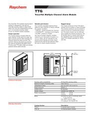
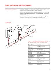
<strong>920</strong> series control assemblies are ordered as three separate items:<br />
Fig. 1.6 <strong>920</strong> series control assemblies<br />
Digi<strong>Trace</strong> <strong>920</strong> SERIES<br />
A<br />
B<br />
STATUS<br />
ALARM MONITOR CONFIG<br />
ALARM<br />
SHIFT A/B<br />
BACK ENTER<br />
OUTPUT<br />
LOCK<br />
PROGRAMMABLE DUAL POINT<br />
HEAT TRACING CONTROLLER<br />
Enclosure assembly Control module(s)<br />
(One for every two circuits)<br />
Tx<br />
Rx<br />
Digi<strong>Trace</strong> <strong>920</strong> SERIES<br />
ALARM MONITOR CONFIG<br />
SHIFT A/B<br />
BACK ENTER<br />
LOCK<br />
Tyco Thermal Controls maintains a shelf stock of enclosure assemblies, control modules, and<br />
consoles. All other enclosure assemblies are built to order. Not all options may be listed. Contact<br />
your local representative for any special applications you may have.<br />
PROGRAMMABLE DUAL POINT<br />
HEAT TRACING CONTROLLER<br />
STATUS<br />
ALARM<br />
OUTPUT<br />
Optional operator<br />
console(s)
Enclosure Assemblies<br />
1.5.1 ENCLOSURE ASSEMBLY<br />
Description Catalog number Part number Weight/lbs<br />
Digi<strong>Trace</strong> <strong>920</strong> controller–2 Pt in a 14" x 12" x 8" FRP enclosure<br />
with window and quick-release latches, control module, and operator<br />
console. 1P 30 A 277 V SSR/pt. Controls two circuits, each<br />
with a 1-pole solid-state relay. (Approved for Class 1, Div. 2 areas)<br />
<strong>920</strong>*E4FWL*SIS302*SS3102*HTC*CON 10160-010 27<br />
Digi<strong>Trace</strong> <strong>920</strong> controller–2 Pt in a 14" x 12" x 8" FRP enclosure<br />
with window and quick-release latches, control module, and operator<br />
console. Includes an isolated 2-wire RS-485 communication<br />
option. 1P 30 A 277 V SSR/pt. Controls two circuits, each with a<br />
1-pole solid-state relay. (Approved for Class 1, Div. 2 areas)<br />
Digi<strong>Trace</strong> <strong>920</strong> controller–2 Pt in a 14" x 12" x 8" FRP enclosure<br />
with window and quick-release latches, control module, and operator<br />
console. 2P 30 A 277 V SSR/pt. Controls two circuits, each<br />
with a 2-pole solid-state relay. (Approved for Class 1, Div. 2 areas)<br />
Digi<strong>Trace</strong> <strong>920</strong> controller–2 Pt in a 14" x 12" x 8" FRP enclosure<br />
with window and quick-release latches, control module, and operator<br />
console. Includes an isolated 2-wire RS-485 communication<br />
option. 2P 30 A 277 V SSR/pt. Controls two circuits, each with a<br />
2-pole solid-state relay. (Approved for Class 1, Div. 2, areas)<br />
<strong>920</strong>*E4FWL*SIS302*SS3102*HTC485*CON 10160-011 27<br />
<strong>920</strong>*E4FWL*SIS302*SS3202*HTC*CON 10160-012 32<br />
<strong>920</strong>*E4FWL*SIS302*SS3202*HTC485*CON 10160-013 32<br />
Digi<strong>Trace</strong>–Digi<strong>Trace</strong><br />
Supervisory Software Digi<strong>Trace</strong> Supervisor 10391-002 1<br />
Note: The NEC (and CEC) rules specify that all ungrounded—i.e., hot—legs of a circuit, must be switched in the event of a ground fault. This means for<br />
207 V single-phase applications, you must specify a 2-pole (2P) version if you are not using external GFI breakers.<br />
Control Modules<br />
Digi<strong>Trace</strong> <strong>920</strong> controller–Control<br />
module only<br />
(No communications options installed)<br />
Digi<strong>Trace</strong> <strong>920</strong> controller–Control<br />
module with an isolated<br />
2-wire RS-485 communication option installed<br />
Digi<strong>Trace</strong> <strong>920</strong> controller–Control<br />
module with modem<br />
communications option installed<br />
<strong>920</strong>HTC 10260-001 1<br />
<strong>920</strong>HTC*485 10260-004 1<br />
<strong>920</strong>HTC*MDM 10260-002 1<br />
Operator Console<br />
Digi<strong>Trace</strong> <strong>920</strong> controller–Operator<br />
console <strong>920</strong>CON 10260-005 1<br />
Contact your local representative for other available configurations that are not listed above.<br />
11
Section 2 Installation and Wiring<br />
2.1 Introduction<br />
2.2 Initial Inspection<br />
2.3 Operator Safety Considerations<br />
2.4 Operating Environment<br />
2.5 Installation Location<br />
12<br />
Caution: Be sure all personnel involved in installation, servicing, and programming are qualified<br />
and familiar with electrical equipment, their ratings and proper practices and codes. Multiple<br />
voltages and signal levels may be present during the installation, operation, and servicing of this<br />
product. Do not power the product until the safety provisions outlined in this section have been<br />
observed.<br />
This section includes information on the initial inspection, preparation for use, and storage<br />
instructions for the <strong>920</strong> series heat trace controller.<br />
Caution: Solid-state relay (SSR) modules may be extremely hot immediately after power is<br />
removed. Exercise care when handling SSRs.<br />
Inspect the shipping container for damage. If the shipping container or cushioning material is<br />
damaged, it should be kept until the contents of the shipment have been verified for completeness<br />
and the equipment has been checked mechanically and electrically. Procedures for configuring<br />
and operating the heat trace controller are given in Section 3 on page 18. If the shipment is<br />
incomplete there is mechanical damage, a defect, or the controller does not pass the electrical<br />
performance tests, notify your Tyco Thermal Controls representative. If the shipping container is<br />
damaged, or the cushioning material shows signs of stress, notify the carrier as well as your<br />
Tyco Thermal Controls representative. Keep the shipping materials for the carrier’s inspection.<br />
The standard <strong>920</strong> controller using solid-state relays is suitable for Class I, Division 2, Groups A,<br />
B, C, D and Zone 2 hazardous areas. Hazardous areas are defined by Article 500 of the National<br />
Electrical Code and Section 18 of the Canadian Electrical Code. Contactor-based assemblies are<br />
suitable for use in ordinary (non-hazardous) areas only.<br />
Caution: Many wiring configurations will use more than one power source and all must be deenergized<br />
prior to performing any maintenance on a controller circuit.<br />
The operating environment should be within the limitations described in the <strong>920</strong> heat trace controller<br />
specifications outlined in Appendix A on page 61.<br />
The wide ambient operating temperature range of the controller permits installation in any convenient<br />
location. Considerations should include expected atmospheric conditions, accessibility<br />
for maintenance and testing, the location of existing conduits, and hazardous area rating. Ambient<br />
temperature conditions may affect load current ratings.<br />
Caution: Always be sure that the intended location is classified as an area that the product is<br />
approved for as defined by Article 500 of the National Electrical Code and/or Part I, Section 18 of<br />
the Canadian Electrical Code.
2.6 Mounting Procedures<br />
Mounting hole dimensions for the standard enclosures are shown in Appendix B on page 63. If<br />
possible, conduit entries should be made in the bottom of the enclosure to reduce the possibility<br />
of water entry or leakage. Conduit entries must be drilled/punched following the enclosure manufacturer’s<br />
recommendations. Use bushings suitable for the enclosure type and install such that<br />
the completed installation remains waterproof. Grounding hubs and conductors must be<br />
installed in accordance with Article 501-4(b) of the National Electrical Code and Part I of the<br />
Canadian Electrical Code.<br />
The user may want to consider enclosure drain holes in applications where moisture is a problem;<br />
drill 0.125" holes in the bottom of the enclosure on both the left and right sides. Two holes<br />
reduce the possibility that one will plug and ensures drainage if the enclosure is not perfectly<br />
level. Note that drilling holes in the enclosure compromises the NEMA 4 rating. <strong>Controller</strong>s<br />
should be removed from the enclosure before any holes are drilled or cut to prevent damage due<br />
to flying debris.<br />
2.6.1 CONTROL MODULE INSTALLATION AND REMOVAL<br />
Caution: Always ensure that the power to the unit is turned off during installation or removal to<br />
avoid the risk of injury and damage to the controllers.<br />
Warning—Explosion Hazard! Do not install or remove the control module while the unit is<br />
powered.<br />
Fig 2.1 Control module installation<br />
The <strong>920</strong> series controller is designed to be mounted to a flat back plate/panel using a terminal<br />
board. This plug-in design simplifies installation and maintenance by allowing all of the lowvoltage<br />
field wiring to remain undisturbed while a control module is installed or removed.<br />
Installation of the control module is easily accomplished by plugging it into the connector on the<br />
terminal board.<br />
• The module is fully inserted once its rear cover is flush to the top surface of the terminal<br />
board. The connectors are designed to be self-aligning, so no undue force should be<br />
required.<br />
• Next, secure the module using the two captive screws provided (one located on each side of<br />
the rear cover). These should thread easily into the terminal board. Be sure to align the<br />
screws properly to avoid cross-threading them.<br />
To remove the control module, loosen the two captive screws. Once they have been completely<br />
loosened, they will float freely in their respective retaining collars without falling out. The module<br />
may now simply be pulled straight out of its connection.<br />
2.6.2 OPERATOR CONSOLE INSTALLATION AND REMOVAL<br />
The operator console is designed to be easily installed or removed while the controller is powered—even<br />
in Class I Division 2 and Zone 2 hazardous areas. It may be temporarily or permanently<br />
installed.<br />
The console is installed in three steps:<br />
13
2.7 Wiring<br />
14<br />
Step 1 “Hook” the lip provided on the rear cover of the console over the top edge of the control<br />
module front plate.<br />
Fig. 2.2 Console installation – Step 1<br />
Step 2 “Hinge” the bottom of the console downwards until it is flush with the front of the control<br />
module.<br />
Fig. 2.3 Console installation – Step 2<br />
Step 3 If the console is to be permanently installed, secure it to the control module using the<br />
captive screw provided. It should be finger tight only. Do not over-tighten the screw or damage<br />
to the console housing may occur.<br />
Fig. 2.4 Console installation – Step 3<br />
To remove the console, follow the three steps outlined above in reverse order.<br />
Wiring diagrams for typical configurations are included in Appendix C on page 68.<br />
Caution: Always verify wiring connections before applying power to the controller or connected<br />
circuits. To avoid injury or equipment damage, do not install or remove wiring while controller<br />
power is on.<br />
To minimize the chance of loose connections, the terminal board uses lever-operated, springloaded<br />
terminals. See Appendix A on page 61 for allowable wire sizes and recommended insulation<br />
strip lengths.
2.7.1 TEMPERATURE SENSOR CONNECTIONS<br />
Use shielded, twisted, three-conductor wire for the extension of RTD leads. The wire size should<br />
ensure that the maximum allowable lead resistance is not exceeded. Shields on RTD wiring<br />
should be grounded at the controller end only, using the terminals provided.<br />
Temperature Sensors Terminal No.<br />
Point A – Shield 25<br />
Point A TS 1 Source (WHT) 26<br />
Point A TS 1 Sense (WHT) 27<br />
Point A TS 1 Common (RED) 28<br />
Point A – Shield 9<br />
Point A TS 2 Source (WHT) 10<br />
Point A TS 2 Sense (WHT) 11<br />
Point A TS 2 Common (RED) 12<br />
Point B – Shield 29<br />
Point B TS 1 Source (WHT) 30<br />
Point B TS 1 Sense (WHT) 31<br />
Point B TS 1 Common (RED) 32<br />
Point B – Shield 13<br />
Point B TS 2 Source (WHT) 14<br />
Point B TS 2 Sense (WHT) 15<br />
Point B TS 2 Common (RED) 16<br />
Note: Some RTDs may be constructed with the Sense wire color-coded as Black.<br />
2.7.2 ALARM RELAY CONNECTIONS<br />
The alarm output relay is a programmable dry contact output. It may be programmed for N.O.,<br />
N.C., steady or flashing operation, and is typically used to annunciate an alarm to an external<br />
device such as a DCS, PLC, etc.<br />
Note: The alarm relay is intended to be used for switching low-voltage, low-current signals. Do<br />
not use this relay to directly switch line voltages. Ensure that your application stays within the<br />
ratings of the relay contacts as defined in Appendix A on page 61.<br />
The alarm relay may also be used in conjunction with the +9 Vdc source to switch an external,<br />
line-voltage relay to drive a local pilot light, etc. Refer to the wiring diagrams in Appendix C on<br />
page 68 for example connection details.<br />
Alarm and Control Signals Terminal No.<br />
Alarm relay dry contact output 17<br />
Alarm relay dry contact output 18<br />
Ground 19<br />
+9 Vdc nominal Out (100 mAmps maximum) 1<br />
Common 2<br />
Common 3<br />
2.7.3 EXTERNAL INPUT/OUTPUT<br />
These input and output terminals are used to implement the Override and Ambient Temperature<br />
Control Mode features. Refer to Section 3 on page 18 for programming details, and Appendix C<br />
on page 68 for example wiring diagrams.<br />
15
16<br />
Miscellaneous Signals Terminal No.<br />
External input (+) 20<br />
External input (-) 21<br />
External output (+) 4<br />
External output(-) 5<br />
2.7.4 COMMUNICATION SIGNAL CONNECTIONS<br />
The communications terminal assignments change based on the type of option installed. If<br />
present in a control module, the type of communications interface will be identified by a label<br />
located next to the module’s rating label.<br />
Communications wiring should use twisted conductor, shielded cable. Shields on communications<br />
wiring should be grounded at one end only, using the terminals provided.<br />
The following tables define the appropriate signal connections for the various types of interfaces:<br />
RS-485 (2-Wire) Connections<br />
Communication Signal Terminal No.<br />
Receive/transmit data (+) 6<br />
Receive/transmit data (-) 22<br />
Shield 8<br />
Shield 24<br />
RS-232 Connections<br />
Communication Signal Terminal No.<br />
Receive data 6<br />
Data carrier detect 7<br />
Clear to send 8<br />
Transmit data 22<br />
Request to send 23<br />
Common 24<br />
Modem Interface Connections (Note that these particular signals are not polarity sensitive)<br />
Communication Signal Terminal No.<br />
Modem 6<br />
Modem 22<br />
Shield 8<br />
Shield 24<br />
2.7.5 POWER CONNECTIONS<br />
All of the power terminals are numbered for easy identification. Do not attempt to use wire sizes<br />
that exceed the marked terminal ratings and avoid terminating two wires on the same terminal<br />
whenever possible.<br />
Always be sure that all terminals are adequately tightened according to the terminal manufacturer’s<br />
specification. See Appendix A on page 61 for allowable wire sizes, recommended insulation<br />
strip lengths, and tightening torque. A loose terminal can cause arcing and damage to the<br />
terminal or incorrect operation of the controller.<br />
Note: Make sure that power terminals are re-tightened several days after installation. Stranded<br />
wire will tend to compress when initially installed; therefore, these terminals should be checked<br />
for tightness several times after the system is installed to ensure that a good connection is main-
2.8 Initial Power-up<br />
tained. Be certain to use the proper size screwdriver for the terminal blocks to minimize the<br />
chance of damage to the terminals.<br />
If the controllers are installed in either a metallic or non-metallic enclosure, follow the enclosure<br />
manufacturer’s recommendations for proper grounding. Do not rely on conduit connections to<br />
provide a suitable ground.<br />
Grounding terminals/screws are provided for connection of system ground leads. Proper system<br />
grounding is required for safe and correct operation of the controller’s protection features.<br />
2.7.6 INPUT POWER<br />
The <strong>920</strong> controller may be powered directly from the trace voltage (120 Vac to 277 Vac),<br />
through a step-down transformer, or from a separate circuit. The same wiring terminal assignments<br />
are used in all configurations, as defined below:<br />
Power Connections Terminal No.<br />
Line/L1 power input 1<br />
Line/L1 Control Power Input 2<br />
Neutral/L2 Power Input 3<br />
Neutral/L2 Control Power Input 4<br />
L3 Power Input (3Ph only) 5<br />
Line/L1 Output to <strong>Trace</strong> 6<br />
Neutral/L2 Output to <strong>Trace</strong> 7<br />
L3 Output to <strong>Trace</strong> (3Ph only) 8<br />
Note that terminals 5 and 8 are only used for implementing 3-phase switching (this is true for<br />
both SSR and contactor configurations).<br />
When powering the controller directly from the incoming trace power (120 Vac to 277 Vac),<br />
jumpers are installed between terminals 1 and 2 and 3 and 4. This is the standard factory configuration.<br />
When the controller is to be powered from another voltage source, the jumpers between<br />
terminals 1 and 2 and 3 and 4 should be removed, and the controller power connected to terminals<br />
2 and 4.<br />
In applications where a neutral-based 4-wire 3-phase source is available, the controller may be<br />
powered from one line to neutral connection, while the trace is operated from the line-to-line<br />
connection, eliminating the need for step-down transformers or separate power sources. This<br />
can be accomplished by removing the jumper between terminals 3 and 4 only. <strong>Controller</strong> power<br />
can then be derived from the L1 trace power on terminals 1 and 2 and the incoming neutral connection<br />
for controller power would be connected to terminal 4.<br />
Wiring diagrams for typical 1- and 2-pole configurations are included in Appendix C on page 68.<br />
Note: The contactor version Switch Interface modules provide a switched line voltage signal to<br />
drive the contactor coil. This is derived from the control power and, as such, requires that the<br />
contactor coil voltage be specified to match the control voltage present on terminals 2 and 4.<br />
Caution: Many wiring configurations will use more than one power source and all must be deenergized<br />
prior to performing any maintenance on a controller circuit. When servicing one control<br />
point, remember that power may also be present on the second control point.<br />
Caution: Before applying power to the controller, ensure that powering the circuit will not damage<br />
it if power limiting or the setpoint temperature have not been set correctly. If there is any<br />
doubt, the load should be disconnected until the <strong>920</strong> has been suitably programmed for correct<br />
and safe operation.<br />
17
2.9 Setup for the <strong>920</strong><br />
Section 3 Programming and Configuration<br />
3.1 Introduction<br />
18<br />
2.8.1 INITIAL CABLE TEST<br />
To minimize the risk of damage to the controller due to a cable fault, the integrity of the heating<br />
cable should be verified by:<br />
1. Using a megger to perform a high-voltage insulation test<br />
2. Using an ohmmeter to ensure that the heating cable is not shorted<br />
These tests must be performed with the controller output disconnected. Once the cable has been<br />
checked, it may be reconnected to the controller and power applied.<br />
2.8.2 RANDOM START DELAY<br />
All <strong>920</strong> series control modules incorporate a RANDOM START-UP DELAY feature, ensuring that all<br />
units do not power on at the same time. When power is first applied to a controller, it will hold its<br />
output off for a random time (0 to 9 seconds), equal to the last digit of the HTCBUS communications<br />
address (see section 3.9.2 on page 43). Once the start-up delay has timed out, the controller<br />
will begin normal operation.<br />
The <strong>920</strong> may be programmed using the optional <strong>920</strong> Operator Console, or a Group Communications<br />
<strong>Controller</strong> (GCC) if the modem communications option is installed. For instructions on the<br />
operation of these devices, refer to the corresponding operating manuals. For complete instructions<br />
on programming the <strong>920</strong>, see the Section 3 on page 18.<br />
2.9.1 VOLTAGE READING SETUP<br />
The <strong>920</strong> series control module is tested, calibrated, and ordered separately from the switch<br />
interface modules which contain the voltage sensing circuitry. This prevents Tyco Thermal<br />
Controls from calibrating the control modules to specific switch interfaces and removing any<br />
component inaccuracies. Generally, the voltage readings will be within 3 Vac to 5 Vac when<br />
shipped from Tyco Thermal Controls. If more accurate voltage readings are desired, they may be<br />
adjusted as part of the initial setup of the controller. This requires measurement of the trace voltage<br />
using a multimeter and adjusting the VOLTAGE TURNS RATIO setting to arrive at more accurate<br />
voltage readings. See section 3.5.21 on page 26.<br />
2.9.2 SWITCH RATING SETUP (SSR ONLY)<br />
The <strong>920</strong> series control module is ordered and shipped as a separate item from the enclosure<br />
assembly. This prevents Tyco Thermal Controls from predetermining the SWITCH CURRENT<br />
RATING settings since various types of output switches are available.<br />
The user should verify that the switch current ratings are set properly for the rating of the solidstate<br />
relays that are included as part of the enclosure assembly. Refer to section 3.5.7 on<br />
page 22 for more information on the SWITCH CURRENT RATING setting. Tyco Thermal Controls<br />
default setting is defined in Appendix F on page 76.<br />
This section provides complete operating and setup instructions for the <strong>920</strong> <strong>Series</strong> <strong>Heat</strong>-Tracing<br />
<strong>Controller</strong>. The text describes each available function in detail, its purpose, valid range settings,<br />
the procedure for use, and some operational tips and suggestions.<br />
While configuring the controller, it is important to remember that the <strong>920</strong> series controller is a<br />
two control point device. Both control points allow completely independent operation and, as<br />
such, have their own individual settings that must be configured. Throughout the text, the first<br />
control point is referred to “Point A” and the second as “Point B.”
3.2 Front Panel Features<br />
3.3 <strong>920</strong> Operator Console Display<br />
Fig 3.1 Digi<strong>Trace</strong> <strong>920</strong> front panel<br />
Front panel features of the heat trace controller are shown in Figure 3.1. The remainder of this<br />
Section describes the front panel status and display LEDs.<br />
3.2.1 <strong>920</strong> FRONT PANEL DISPLAY<br />
The basic <strong>920</strong> series control module front panel includes seven LED indicators. Four of these are<br />
used to indicate the “Output” and “Alarm” status of control points A and B.<br />
Status LEDs<br />
“Power On” LED<br />
Communications status<br />
indicators<br />
Alarm status<br />
indicators<br />
Output status<br />
indicators<br />
ALARM<br />
OUTPUT<br />
A B<br />
<strong>920</strong> SERIES<br />
OUTPUT The OUTPUT LED, when illuminated steadily, indicates that the output of the controller is<br />
turned on and is allowing current to flow in the trace circuit. For SSR versions, a flashing LED<br />
indicates that the controller is pulsing its output on and off to maintain the setpoint temperature<br />
and/or control the average amount of current/power the tracer uses. A separate LED is provided<br />
for Point A and Point B.<br />
ALARM The ALARM LEDs will flash (approximately once per second) when the controller has<br />
detected an alarm condition. A separate LED is provided for Point A and Point B.<br />
TRANSMIT The TRANSMIT LED (“Tx”) flashes when the controller is sending information over its<br />
communications port to another device. This LED is only used when an optional communications<br />
interface is installed.<br />
RECEIVE The “RECEIVE” LED (“Rx”) flashes when the controller is receiving information over its<br />
communications port from another device. This LED is only used when an optional communications<br />
interface is installed.<br />
POWER Indicates the module is powered on.<br />
POWER<br />
TRANSMIT<br />
RECEIVE<br />
ADDRESS<br />
A - 20910<br />
B - 20911<br />
Note: Older versions of the controller may not have this LED.<br />
PROGRAMMABLE DUAL POINT<br />
HEAT TRACING CONTROLLER<br />
CONSOLE INTERFACE<br />
Communications addresses<br />
for Control Point A and<br />
Control Point B<br />
Operator<br />
console<br />
connection<br />
The optional <strong>920</strong> Operator Console provides a menu-driven, alphanumeric interface to ease configuration<br />
and troubleshooting. The following features are part of the controller’s programming,<br />
but are only used in conjunction with the <strong>920</strong> Operator Console. For a detailed description of<br />
each of the console features and operating instructions, refer to the separate Digi<strong>Trace</strong> <strong>920</strong><br />
<strong>Series</strong> HTC Operator Console—Installation and Operating Instructions (Tyco Thermal Controls<br />
reference H56903).<br />
19
3.4 <strong>920</strong> Functions<br />
3.5 Control Point Setup<br />
20<br />
The sections that follow explain the various functions of the <strong>920</strong> controller and how they can be<br />
accessed. The first line of each section identifies the function to be described. Each section goes<br />
on to explain the Purpose of the function, the Range over which it may be set, the Procedure for<br />
setting or enabling the feature, and finally any Notes or Cautions that pertain to the particular<br />
function.<br />
Setting and using the alarming functions of the <strong>920</strong> controller is a two step procedure:<br />
1. The alarm must be enabled or disabled accordingly. When using the <strong>920</strong> Operator Console,<br />
access to all alarming functions is available using the CONFIGURE mode sub-menus. When<br />
using the Model 780/GCC-9000 Group Communications <strong>Controller</strong>, the alarm masks may be<br />
found in the HTC SETUP Section. Please see the appropriate operating manual for instructions<br />
on accessing these parameters.<br />
2. The corresponding alarm point value may be modified appropriately for the application.<br />
When using the <strong>920</strong> Operator Console, access to the alarm points is also available using the<br />
CONFIGURE mode sub-menus. Modification of the alarm setpoint values is found in the HTC<br />
SETPOINTS Section of the Model 780/GCC-9000 Group Communications <strong>Controller</strong>. Please<br />
see the appropriate operating manual for instructions on accessing this feature.<br />
Note: The <strong>920</strong> Operator Console or the Model 780/GCC-9000 will not allow modification of an<br />
alarm point value if the alarm has been disabled (DIS) with the exception of the HIGH TS ALARM<br />
temperature settings. These may still be modified if the corresponding HIGH LIMIT CUTOUT has<br />
been enabled (ENA).<br />
This Section describes the setup parameters that relate to a specific control point—either Point<br />
A or Point B. These parameters must be configured for each of the two control points that are<br />
used.<br />
3.5.1 CONTROL SETPOINT TEMPERATURE<br />
Purpose: The CONTROL SETPOINT temperature is the value at which the heat trace controller<br />
maintains the circuit temperature through either proportional, proportional ambient SSR, proportional<br />
ambient contactor, or deadband control, depending on the controllers’ configuration. The<br />
CONTROL SETPOINT temperature is compared to the temperature measured by the control temperature<br />
sensor (TS). A decision is then made to turn on or turn off the output to control power<br />
to the tracer.<br />
Range: –76°F to 1058°F (–60°C to 570°C)<br />
Procedure: Adjust the CONTROL SETPOINT temperature value to the desired maintain temperature.<br />
The HTC will switch the output ON and OFF in an attempt to maintain this temperature.<br />
Notes:<br />
• See section 5.2 on page 50 of this manual for an explanation of Proportional, Proportional<br />
Ambient SSR, Proportional Ambient Contactor and Deadband Control algorithms.<br />
• When using an optional <strong>920</strong> Operator Console (for V3.11 and up) the CONTROL SETPOINT<br />
temperature range may be limited to the CONSOLE SETPOINT MAXIMUM and MINIMUM values<br />
(see sections 3.5.29 on page 29 and 3.5.30 on page 29). This is a safety feature to prevent<br />
users in the field from modifying the CONTROL SETPOINT temperature setting to a dangerous<br />
level.<br />
3.5.2 ALPHANUMERIC TAG ASSIGNMENT<br />
Purpose: A 19-character alphanumeric TAG may be assigned to a control point to allow it to be<br />
easily associated with a pipe, vessel, process, circuit, drawing name or number.<br />
Setting: Any combination of 19 characters from A-Z, 0-9, /, -, ., (,) or #.
Procedure: Using the <strong>920</strong> Operator Console, enter the desired text. Refer to the separate<br />
Digi<strong>Trace</strong> <strong>920</strong> <strong>Series</strong> HTC Operator Console—Installation and Operating Instructions (Tyco Thermal<br />
Controls reference H56903) for TAG entry information.<br />
3.5.3 SWITCH CONTROL MODE<br />
Purpose: This allows selection of the type of algorithm to be used by the HTC to maintain the<br />
CONTROL SETPOINT temperature. There are four different control algorithms available in the<br />
HTC—proportional, proportional ambient SSR, proportional ambient contactor, and deadband.<br />
See section 5.2 on page 50 for a complete explanation of these controlling techniques as implemented<br />
in the HTC.<br />
Setting: PROPORTIONAL, PROPORTIONAL AMBIENT SSR (V3.11+), PROPORTIONAL AMBIENT CON-<br />
TACTOR (V3.11+), or DEADBAND<br />
Procedure: Select the desired control technique. Note that deadband control and proportional<br />
ambient contactor should be selected when using contactors or when precise control and<br />
advanced current handling functions are not required.<br />
Note: If deadband is selected, a DEADBAND setting will be available in the HTC configuration<br />
menu, else a PROPORTIONAL BAND setting will be available. No MAXIMUM POWER, SWITCH CUR-<br />
RENT RATING or CIRCUIT BREAKER CURRENT RATING settings are available when the controller is<br />
set to operate in either contactor mode. If proportional ambient contactor is selected, the CYCLE<br />
TIME setting will also be available.<br />
3.5.4 PROPORTIONAL BAND SETTING<br />
(For use with the three proportional control modes only)<br />
Purpose: When an HTC equipped with SSRs is used to control a heating circuit, proportional or<br />
proportional ambient SSR modes are normally used, allowing for more precise temperature control.<br />
When using contactors, the proportional ambient contactor mode should be selected.<br />
This programmable proportional band acts to vary the on to off time of the output based on the<br />
difference between the measured control temperature and the desired CONTROL SETPOINT<br />
temperature.<br />
Range: 2°F to 90°F (1°C to 50°C)<br />
2°F to 630°F (1°C to 350°C) V3.2x and up<br />
Procedure: Adjust the PROPORTIONAL BAND setting to the desired differential from the CONTROL<br />
SETPOINT temperature.<br />
Notes:<br />
• See section 5.2 on page 50 for an explanation of how the three proportional modes use the<br />
PROPORTIONAL BAND setting.<br />
• When using series-type, constant wattage, or self-regulating tracers in an ambient temperature<br />
control application, significant energy savings may be realized by setting the PROPOR-<br />
TIONAL BAND to match the expected range of operating ambient temperatures. <strong>Trace</strong>r design<br />
is normally done assuming worst-case conditions, where 100% of the design output power<br />
is required to maintain the desired minimum temperature. When the ambient temperature is<br />
above the design minimum but some heat is still required, adjusting the PROPORTIONAL BAND<br />
width accordingly will allow only the amount of power required by the application to be consumed,<br />
while maintaining the minimum required temperature.<br />
Example: A water line must be protected from freezing when the ambient temperature falls<br />
below 10°C. Either the proportional ambient SSR or proportional ambient contactor mode is<br />
selected as the control method (depending on the type of switch being used). The heater and<br />
insulation are chosen to impart enough heat to the line to keep it from freezing at a worst-case<br />
ambient temperature of –40°C. At 10°C, the heater should be completely off, since no heat is<br />
required at this temperature to guarantee that the product will not freeze. It follows that the<br />
amount of heat required by the water line decreases as the ambient temperature increases from<br />
–40°C to 10°C (theoretically, at –15°C the heater output should be approximately 50%). Setting<br />
21
22<br />
the CONTROL SETPOINT temperature to 10°C, and the PROPORTIONAL BAND to 50°C, will force the<br />
controller’s output to be 100% on at –40°C, 50% on at –15°C, and off at 10°C.<br />
3.5.5 DEADBAND SETTING<br />
(Deadband control mode only or if a point controls an INHIBIT output signal)<br />
Purpose: When an HTC equipped with a contactor is used to control a trace circuit, it is necessary<br />
to use deadband rather than proportional control. This is done to prevent the contactor<br />
from switching on and off rapidly and being worn out prematurely. This deadband acts as an on/<br />
off control where the decision to turn the output off or on is based upon a window of difference<br />
between the measured control temperature and the desired CONTROL SETPOINT temperature.<br />
Range: 2°F to 90°F (1°C to 50°C)<br />
Procedure: Adjust the DEADBAND setting to the desired differential from the desired CONTROL<br />
SETPOINT temperature. When the control temperature is above the setpoint + deadband value,<br />
the controller will turn off the output to the tracer. If the control temperature drops down below<br />
the setpoint, the output will be turned back on. Note that the smaller the DEADBAND setting, the<br />
more often the contactor will cycle on and off, decreasing its operational life.<br />
Notes:<br />
• See section 5.2 on page 50 for an explanation of deadband control. Note that the MAXIMUM<br />
POWER, SWITCH CURRENT RATING, and CIRCUIT BREAKER CURRENT RATING settings are not<br />
available when the HTC is set to deadband mode (typically when switching a contactor).<br />
• The DEADBAND parameter is also available for Point A when the EXTERNAL OUTPUT is configured<br />
for use as an INHIBIT output. See section 3.6.4 on page 30 for additional details.<br />
3.5.6 CYCLE TIME SETTING (V3.11 AND UP)<br />
(For proportional ambient contactor control mode only)<br />
Purpose: This parameter determines the minimum amount of time it will take for a complete<br />
contactor ON-OFF-ON cycle.<br />
Range: 10 to 255 minutes<br />
Procedure: Adjust the CYCLE TIME setting to yield the desired contactor ON+OFF time for a particular<br />
duty cycle. For instance, if the contactor should remain on for five minutes with a 50% duty<br />
cycle, then the CYCLE TIME should be 10 minutes. A new duty cycle (based on measured control<br />
temperature, PROPORTIONAL BAND and CONTROL SETPOINT) is calculated every time the contactor<br />
is required to change state.<br />
Notes:<br />
• If the calculated duty cycle is 0% or 100%, then the contactor will not change state and the<br />
duty cycle will not be calculated again for a time period = CYCLE TIME/30.<br />
• The minimum cycle time setting is 10 minutes, and the minimum controller output duty cycle<br />
is 3%. This results in a minimum contactor ON time of 18 seconds.<br />
3.5.7 SWITCH CURRENT RATING SETTING (SSR ONLY)<br />
Purpose: The SWITCH CURRENT RATING setting defines the current rating of the output switch. It<br />
is used by the controller to limit the maximum average current that will be allowed to flow to the<br />
load before it begins to adjust the output duty cycle, limiting the amount of current to an acceptable<br />
level.<br />
Range: 0.3 to 100.0 amps<br />
(CURRENT TURNS RATIO = 1.00)<br />
Procedure: Adjust the SWITCH CURRENT RATING setting to match the current rating of the output<br />
device (i.e. 30.0 amps). Note that the SWITCH CURRENT RATING setting is affected by the<br />
CURRENT TURNS RATIO setting. The absolute maximum adjusted SWITCH CURRENT RATING setting<br />
is 300.0 amps. The absolute minimum adjusted SWITCH CURRENT RATING setting is 0.1 amps.<br />
See section 3.5.22 on page 26 for more information regarding the CURRENT TURNS RATIO<br />
function.
3.5.8 CIRCUIT BREAKER CURRENT RATING SETTING (SSR ONLY)<br />
Purpose: The CIRCUIT BREAKER CURRENT RATING setting helps prevent in-rush induced nuisance<br />
tripping of the circuit breaker immediately upstream of the controller. The HTC evaluates the<br />
square of the current related to time (I 2 T) and adjusts the output duty cycle accordingly, limiting<br />
the amount of current to an acceptable level.<br />
Range: 0.3 to 100.0 amps<br />
(CURRENT TURNS RATIO = 1.00)<br />
Procedure: Adjust the CIRCUIT BREAKER CURRENT RATING setting to the heating circuit breaker<br />
size (i.e. 30.0 amps). Note that the CIRCUIT BREAKER CURRENT RATING setting is affected by the<br />
CURRENT TURNS RATIO setting. The absolute maximum adjusted CIRCUIT BREAKER CURRENT RAT-<br />
ING setting is 300.0 amps. The absolute minimum adjusted CIRCUIT BREAKER CURRENT RATING<br />
setting is 0.1 amps. See section 3.5.22 on page 26 for more information regarding the CURRENT<br />
TURNS RATIO function.<br />
Note: This feature should not be used to reduce the size of a circuit breaker or increase the maximum<br />
heating cable length. It can be quite effective in preventing nuisance trips due to incorrect<br />
design or factors outside those considered by the design.<br />
3.5.9 MAXIMUM POWER SETTING (SSR ONLY)<br />
Purpose: This user-selectable level limits the maximum amount of power applied to a heat trace<br />
circuit. This is an average power calculated by the controller using the average current and<br />
applied voltage. The HTC switches the output on and off rapidly to limit the average current to an<br />
appropriate level. The MAXIMUM POWER level may be adjusted to eliminate step-down transformers,<br />
lower the effective output wattage of a cable, or implement energy management of the heat<br />
trace circuit.<br />
Range: 3 to 33,000 Watts<br />
(VOLTAGE and CURRENT TURNS RATIOS = 1.00)<br />
Procedure: Adjust the MAXIMUM POWER level to the desired value (watts). Use the TEST TRACING<br />
function to observe the power limiting operation.<br />
Notes:<br />
• This function may be set within reasonable limits for the particular tracer being powered. The<br />
effective resolution of the setting is limited to 1/30th of the calculated full on power.<br />
• Do not set the MAXIMUM POWER below full output for applications that do not require control<br />
of power.<br />
• This feature is affected by the VOLTAGE and CURRENT TURNS RATIO settings. The maximum<br />
range using adjusted values of voltage and current is 65,535 watts. See sections 3.5.21 on<br />
page 26 and 3.5.22 on page 26 for more information regarding the turns ratio functions.<br />
3.5.10 3-PHASE POWER CALCULATION (V3.11 AND UP)<br />
Purpose: This parameter selects the type of power calculation that the HTC is to perform.<br />
Setting: NO or YES<br />
Procedure: If an automatic 3-phase power calculation is desired, select YES. If a normal power<br />
calculation is desired, select NO.<br />
Note: For the total 3-phase power calculation to be accurate the following conditions must be<br />
met:<br />
• All three phases must be balanced and star (“Y”) connected<br />
• The measured corrected current is one of the phase currents<br />
• The measured corrected voltage is the line to line voltage<br />
The formula used to calculate this total power is: P total = √3 x I phase x V line-line<br />
3.5.11 TS FAIL MODE (V3.11 AND UP)<br />
Purpose: This parameter determines whether the HTC turns the output switch ON or OFF if all<br />
selected temperature sensors fail to provide a control temperature.<br />
23
24<br />
Setting: OFF or ON<br />
Procedure: If the HTC should turn the output switch off when it cannot read a valid control temperature,<br />
then select OFF; otherwise, if the output switch should turn on, then select ON.<br />
Note: This parameter is part of the TS CONTROL MODE.<br />
3.5.12 TEMPERATURE SENSOR CONTROL MODE<br />
Purpose: The TS CONTROL MODE allows the selection of one of eleven possible temperature control<br />
modes for the controller. The different modes allow redundant fail-safe temperature sensing,<br />
averaging, or minimum maintain temperature control.<br />
Setting: Select one of the following eleven possible modes:<br />
Control TS and Description<br />
CONTROL USING TS 1, FAIL OFF/ON<br />
CONTROL USING TS 1, FAIL TO TS 2<br />
CONTROL USING TS 2, FAIL OFF/ON<br />
CONTROL USING TS 2, FAIL TO TS 1<br />
CONTROL ON AVERAGE, FAIL OFF/ON<br />
CONTROL ON AVERAGE, FAIL TO GOOD<br />
CONTROL ON LOWEST, FAIL OFF/ON<br />
CONTROL ON LOWEST, FAIL TO GOOD<br />
The following are only available in V3.11+:<br />
CONTROL USING EXT. INPUT, FAIL OFF/ON<br />
CONTROL USING EXT. INPUT, FAIL TO TS 1<br />
CONTROL USING EXT. INPUT, FAIL TO TS 2<br />
Where OFF/ON = <strong>Controller</strong>’s output switch turned OFF or ON as determined by the TS FAIL MODE.<br />
Example: With a TS CONTROL MODE of CONTROL ON AVERAGE, FAIL TO GOOD, the controller will<br />
measure both sensors (TS 1 and TS 2), averaging the two temperature value;, display the results;<br />
and cycle the heater ON or OFF to maintain the CONTROL SETPOINT temperature. This is the primary<br />
control mode. If either sensor should fail, the controller will transfer control to the remaining<br />
“good” sensor and generate the appropriate TS 1 or TS 2 FAILURE ALARM (assuming that the<br />
alarm is enabled). The temperature will now be maintained based on this measured value. If the<br />
remaining good sensor fails, the controller will turn the heater OFF or ON as determined by the TS<br />
FAIL MODE setting. The appropriate TS 1 or TS 2 FAILURE ALARM will be also be generated.<br />
Procedure: Select the control mode that best suits the application.<br />
Notes:<br />
• Ensure that TS FAILURE ALARMS are enabled. See sections 3.7.1 on page 32, 3.7.4 on<br />
page 32, and 3.7.10 on page 34 for a complete explanation of RTD failure detection in the<br />
HTC.<br />
• If the selected TS CONTROL MODE uses the EXTERNAL INPUT then the EXTERNAL INPUT must be<br />
set to TEMPBUS (see Section 3.6.3). Also, the CONTROL TS FAILURE ALARM is non-latching in<br />
this mode.<br />
• Fail safe mode is always disabled if the TS CONTROL MODE = EXT. INPUT, FAIL OFF/ON.<br />
3.5.13 TS 1 TYPE (V3.11 AND UP)<br />
Purpose: This parameter specifies the type of RTD that is connected to the HTC’s TS 1 input.<br />
Setting: 3-wire 100 Ω platinum or 2-(or 3-) wire 100 Ω nickel-iron (Ni-Fe)<br />
Procedure: Select the type of RTD that is connected to the TS 1 input.<br />
Note: If a 2-wire 100 Ω nickel-iron (Ni-Fe) RTD is selected then the TS 1 LEAD RESISTANCE must<br />
be entered manually (see section 3.5.14 on page 24).<br />
3.5.14 TS 1 LEAD RESISTANCE (V3.11 AND UP)<br />
(For Ni-Fe RTDs only)
Purpose: This parameter specifies the lead resistance of a 2-wire nickel-iron RTD connected to<br />
the HTC’s TS 1 input.<br />
Range: 0 to 20.00 Ω<br />
Procedure: Measure the resistance of one of the nickel-iron RTD leads (from the RTD to the HTC’s<br />
TS 1 input) and use this value as the TS 1 LEAD RESISTANCE.<br />
3.5.15 TS 1 HIGH LIMIT CUTOUT<br />
Purpose: When enabled, the TS 1 HIGH LIMIT CUTOUT feature will override the CONTROL SETPOINT<br />
temperature and force the controller output off if the TS 1 reading exceeds the HIGH TS 1 ALARM<br />
temperature setting. This is a non-latching condition, so once the TS 1 reading drops below the<br />
HIGH TS 1 ALARM temperature setting, the controller will resume normal operation.<br />
Setting: ENABLE or DISABLE<br />
Procedure: Enable or disable the cutout feature as desired.<br />
Notes:<br />
• The TS 1 HIGH LIMIT CUTOUT feature overrides an autocycle test. A pending autocycle will be<br />
initiated immediately after the TS 1 temperature drops below the HIGH TS 1 ALARM temperature<br />
setting.<br />
• If a TS 1 failure occurs and the TS 1 HIGH LIMIT CUTOUT feature is enabled, the switch output<br />
will latch off regardless of the TS CONTROL MODE setting or the TS FAIL MODE setting.<br />
• If the TS 1 HIGH LIMIT CUTOUT feature is enabled, then the HIGH TS 1 ALARM temperature setting<br />
can be set, regardless of whether the HIGH TS 1 ALARM is enabled.<br />
3.5.16 TS 2 TYPE (V3.11 AND UP)<br />
Purpose: This parameter specifies the type of RTD that is connected to the HTC’s TS 2 input.<br />
Setting: 3-wire 100 Ω platinum or 2- (or 3-) wire 100 Ω nickel-iron (Ni-Fe)<br />
Procedure: Select the type of RTD that is connected to the TS 2 input.<br />
Note: If a 2-wire 100 Ω nickel-iron (Ni-Fe) RTD is selected then the TS 2 LEAD RESISTANCE must<br />
be entered (see section 3.5.17 on page 25).<br />
3.5.17 TS 2 LEAD RESISTANCE (V3.11 AND UP)<br />
(For Ni-Fe RTDs only)<br />
Purpose: This parameter specifies the lead resistance of a 2-wire nickel-iron RTD connected to<br />
the HTC’s TS 2 input.<br />
Range: 0 to 20.00 Ω<br />
Procedure: Measure the resistance of one of the nickel-iron RTD leads (from the RTD to the HTC’s<br />
TS 2 input) and use this value as the TS 2 LEAD RESISTANCE.<br />
3.5.18 TS 2 HIGH LIMIT CUTOUT<br />
Purpose: When enabled, the TS 2 HIGH LIMIT CUTOUT feature will override the CONTROL SETPOINT<br />
temperature and force the controller output off if the TS 2 reading exceeds the HIGH TS 2 ALARM<br />
temperature setting. This is a non-latching condition, so once the TS 2 reading drops below the<br />
HIGH TS 2 ALARM temperature setting, the controller will resume normal operation.<br />
Setting: ENABLE or DISABLE<br />
Procedure: Enable or disable the cutout feature as desired.<br />
Notes:<br />
• The TS 2 HIGH LIMIT CUTOUT feature overrides an autocycle test. A pending autocycle will be<br />
initiated immediately after the TS 2 temperature drops below the HIGH TS 2 ALARM temperature<br />
setting.<br />
• If a TS 2 failure occurs and the TS 2 HIGH LIMIT CUTOUT feature is enabled, the switch output<br />
will latch off regardless of the TS CONTROL MODE setting or the TS FAIL MODE setting.<br />
25
26<br />
• If the TS 2 HIGH LIMIT CUTOUT feature is enabled, then the HIGH TS 2 ALARM temperature setting<br />
can be set, regardless of whether the HIGH TS 2 ALARM is enabled.<br />
3.5.19 VOLTAGE SOURCE (V3.11 AND UP)<br />
Purpose: This parameter specifies which voltage source the HTC should use for its voltage measurements.<br />
Setting: POINT A or POINT B or FIXED<br />
Procedure: If the HTC is not powered from a dedicated switch interface an alternate voltage<br />
source can be selected. If a fixed constant voltage value is to be used then that FIXED VOLTAGE<br />
SETTING must also be entered (see section 3.5.20 on page 26).<br />
Notes:<br />
• If an alternate voltage source is selected, then all voltage alarming features are disabled for<br />
this HTC and the VOLTAGE TURNS RATIO is not used.<br />
• It is not possible to set both points to use the others’ voltage source.<br />
3.5.20 FIXED VOLTAGE SETTING (V3.11 AND UP)<br />
(Only if VOLTAGE SOURCE = FIXED)<br />
Purpose: This parameter specifies the voltage value that the HTC should use when the VOLTAGE<br />
SOURCE = FIXED.<br />
Range: 0 to 1000 Volts<br />
Procedure: Adjust the FIXED VOLTAGE setting to the desired level.<br />
Note: All voltage alarming features are disabled for this HTC and the VOLTAGE TURNS RATIO is not<br />
used when the VOLTAGE SOURCE is set to FIXED.<br />
3.5.21 VOLTAGE TURNS RATIO ADJUSTMENT<br />
Purpose: The VOLTAGE TURNS RATIO adjusts voltage readings for applications where a controller<br />
is switching a load through a step-up or step-down transformer, or is being powered from a<br />
source with a different voltage level than the trace voltage.<br />
Range: 0.10 to 9.90 (TO 1)<br />
Procedure: Adjust the VOLTAGE TURNS RATIO to equal the ratio of the circuit voltage to the controller<br />
input voltage. Compare the indicated voltage to the measured voltage after setting the<br />
turns ratio and adjust until the two readings are as close as possible.<br />
e.g.: <strong>Heat</strong>ing Circuit Voltage: 480 Volts<br />
Module Input Voltage: 120 Volts<br />
VOLTAGE TURNS RATIO Setting: 4.00<br />
Notes:<br />
• When the VOLTAGE TURNS RATIO has been set appropriately, the HTC will calculate the circuit<br />
power using the adjusted current and voltage readings. Voltage alarms also use the adjusted<br />
circuit voltages.<br />
• The VOLTAGE TURNS RATIO is not used if the selected VOLTAGE SOURCE is not from the dedicated<br />
switch interface.<br />
3.5.22 CURRENT TURNS RATIO ADJUSTMENT<br />
Purpose: The CURRENT TURNS RATIO adjusts current readings for applications where a controller<br />
is monitoring a load through an external step-up or step-down current transformer.<br />
Range: 0.10 to 60.00 (TO 1)<br />
Procedure: Adjust the CURRENT TURNS RATIO to equal the ratio of the primary to secondary<br />
windings of the external current transformer. Compare the indicated current to the measured<br />
current after setting of the CURRENT TURNS RATIO and adjust until the two readings are as close<br />
as possible.
Note: When the CURRENT TURNS RATIO has been set appropriately, the HTC will calculate the circuit<br />
power using the adjusted current and voltage readings. Current alarms, as well as the switch<br />
and circuit breaker limiting functions, also use the adjusted circuit currents.<br />
3.5.23 AUTOCYCLE ENABLING<br />
Purpose: The autocycle function momentarily (approximately 10 seconds) applies power to the<br />
heating circuit at the selected interval. It is used to test the integrity of the heating circuit. Alarms<br />
present at the time of autocycle then become latched and remain active after the completion of<br />
the autocycle function. Auto-cycling effectively eliminates the need for preventive maintenance<br />
by automatically verifying the heating circuit integrity.<br />
Setting: ENABLE or DISABLE<br />
Procedure: Enable or disable the auto-cycling feature as desired. If the feature is disabled, you<br />
will not be prompted to enter the AUTOCYCLE INTERVAL or AUTOCYCLE UNITS.<br />
Notes:<br />
• Auto-cycling should always be enabled for normal operation. Disabling this feature should<br />
only be required where the HTC system is monitoring a circuit exercised by some other<br />
device or means. Although this function defeats temperature control and forces output on,<br />
the controller will continue to adjust the output for protection purposes or power limiting<br />
(SSR option only).<br />
• Auto-cycling is inhibited if the controller is in the load shedding mode. See section 5.3 on<br />
page 52.<br />
• If auto-cycling is enabled, the HTC will always autocycle for 10 seconds when power is initially<br />
applied.<br />
• If auto-cycling is enabled, TS FAIL MODE = OFF and all the control temperature sensors have<br />
failed, the HTC will still perform an autocycle.<br />
• If an alarm condition, with an alarm filter time greater than 0, appears during the autocycling,<br />
then the autocycle may be extended (past the 10 seconds) until the alarm filter time<br />
has expired.<br />
3.5.24 AUTOCYCLE TIME INTERVAL<br />
Purpose: AUTOCYCLE INTERVAL is the number of hours/minutes between successive heating circuit<br />
integrity tests depending on the AUTOCYCLE UNITS specified.<br />
Range: 1 to 240<br />
Procedure: Set the AUTOCYCLE INTERVAL to the desired time period.<br />
Notes:<br />
• When using proportional ambient contactor mode, the CYCLE TIME setting should be less<br />
than the AUTOCYCLE INTERVAL otherwise auto-cycling could affect the duty cycle.<br />
• If an AC ALARM becomes active during an autocycle, but the AUTOCYCLE INTERVAL expires<br />
prior to the corresponding ALARM FILTER time, then auto-cycling will continue until the<br />
ALARM FILTER time has elapsed.<br />
• For the earliest possible alarming of heating circuit problems the AUTOCYCLE INTERVAL<br />
should be set to a small value.<br />
3.5.25 AUTOCYCLE TIME UNITS<br />
Purpose: The autocycle time units parameter allows selection of minutes or hours for the<br />
AUTOCYCLE INTERVAL setting.<br />
Setting: HOURS or MINUTES<br />
Procedure: Set the AUTOCYCLE UNITS to the desired time units.<br />
3.5.26 INHIBIT CONTROL (V3.00 ONLY)<br />
Purpose: This feature allows the HTC’s EXTERNAL INPUT to override the controller’s temperature<br />
control and force the output switch off. This is especially useful when the user wishes to turn a<br />
controller or a group of controllers off over the summer months, during maintenance, or when a<br />
line is flowing and does not require heating.<br />
27
28<br />
Setting: ENABLE or DISABLE<br />
Procedure: Enable or disable the INHIBIT CONTROL for the control point being programmed.<br />
Notes:<br />
• The EXTERNAL INPUT must also be programmed as INHIBIT before this parameter can be set.<br />
See section 3.6.3 on page 29 for further details.<br />
• If the autocycle feature is enabled, it will continue to function even when the INHIBIT mode is<br />
active.<br />
• Fail-safe mode is inactive if the INHIBIT mode is active.<br />
• Both of the LOW TS ALARMS are inactive if the INHIBIT mode is active.<br />
3.5.27 OVERRIDE SOURCE (V3.11 AND UP)<br />
Purpose: An override signal can be sent to the HTC from one of two sources. This override signal<br />
can be used to override the controller’s temperature control and force the output switch off or<br />
on. This is especially useful when the user wishes to turn a controller or a group of controllers<br />
off over the summer months, during maintenance, or when a line is flowing and does not require<br />
heating.<br />
Setting: REMOTE or EXT. INPUT<br />
Procedure: If the override signal will be generated remotely and received by the HTC via the<br />
optional communications interface, select REMOTE as the OVERRIDE SOURCE. If the override signal<br />
will be received by the HTC via the external input terminals on the <strong>920</strong> terminal board, select<br />
EXTERNAL INPUT as the OVERRIDE SOURCE.<br />
Notes:<br />
• If the EXTERNAL INPUT is not configured as either INHIBIT or FORCE ON then OVERRIDE SOURCE<br />
will always automatically be set to REMOTE. See section 3.6.3 on page 29 for further details.<br />
• If the autocycle feature is enabled, it will continue to function even when an INHIBIT override<br />
signal is being received as long as load shedding is not active.<br />
• Fail-safe mode is inactive if an INHIBIT override signal is being received.<br />
• Load shedding and fail-safe mode are inactive if a FORCE ON override signal is being received.<br />
• Only the LOW TS ALARMS for temperature sensors used by the TS CONTROL MODE are inactive<br />
if an INHIBIT override signal is being received.<br />
3.5.28 LOAD SHEDDING ENABLING<br />
Purpose: The load shedding function allows the controller output to be forced OFF by way of a<br />
remote contact input on the 780 Group Communications <strong>Controller</strong> or using the communications<br />
port and an upstream device. It may be used to turn OFF the output of one or more controllers<br />
in order to reduce energy consumption to avoid peak demand surcharges, remove power<br />
from unused circuits, or remove power from circuits that may be subjected to steam cleaning.<br />
Setting: ENABLE or DISABLE<br />
Procedure: Enable or disable the load shedding control mode as desired.<br />
Notes:<br />
• To completely configure the HTC for load shedding operation, the following additional parameters<br />
must be set up if using the Model 780/GCC-9000:<br />
– Fail-safe mode<br />
– Load shedding GCC contact association<br />
• These additional parameters may only be accessed using the Group Communications <strong>Controller</strong>.<br />
See the appropriate section of the GCC manual for further details.<br />
• Fail-safe mode is not supported when using proportional ambient SSR mode or proportional<br />
ambient contactor mode.<br />
• Fail-safe mode is not supported if the TS CONTROL MODE = EXT. INPUT, FAIL OFF/ON.<br />
• For fail-safe mode to function, at least one LOW TS ALARM of the controlling temperature sensor(s)<br />
must be enabled and the corresponding LOW TS ALARM temperature setting must be<br />
less than the CONTROL SETPOINT temperature.
3.6 Common <strong>Controller</strong> Setup<br />
3.5.29 CONSOLE SETPOINT MAXIMUM (V3.11 AND UP)<br />
Note: The CONSOLE SETPOINT MAXIMUM is not displayed on the optional <strong>920</strong> Operator Console.<br />
Purpose: When using an optional <strong>920</strong> Operator Console (for V3.11 and up) the maximum setting<br />
of the CONTROL SETPOINT temperature may be limited to the CONSOLE SETPOINT MAXIMUM<br />
value. This is a safety feature to prevent users in the field from modifying the CONTROL SETPOINT<br />
temperature setting to a dangerous level.<br />
Range: –76°F to 1058°F (–60°C to 570°C)<br />
Procedure: Adjust the CONSOLE SETPOINT MAXIMUM temperature value to limit the maximum<br />
allowable CONTROL SETPOINT TEMPERATURE that may be set using the optional <strong>920</strong> Operator<br />
Console. The CONSOLE SETPOINT MAXIMUM may only be set using a communicating device such<br />
as the Model 780/GCC-9000. See the 780/GCC-9000 manual for the proper procedure.<br />
3.5.30 CONSOLE SETPOINT MINIMUM (V3.11 AND UP)<br />
Note: The CONSOLE SETPOINT MINIMUM is not displayed on the optional <strong>920</strong> Operator Console.<br />
Purpose: When using an optional <strong>920</strong> Operator Console (for V3.11 and up) the minimum setting<br />
of the CONTROL SETPOINT temperature may be limited to the CONSOLE SETPOINT MINIMUM value.<br />
This is a safety feature to prevent users in the field from modifying the CONTROL SETPOINT temperature<br />
setting to a dangerous level.<br />
Range: –76°F to 1058°F (–60°C to 570°C)<br />
Procedure: Adjust the CONSOLE SETPOINT MINIMUM temperature value to limit the minimum<br />
allowable CONTROL SETPOINT TEMPERATURE that may be set using the optional <strong>920</strong> Operator<br />
Console. The CONSOLE SETPOINT MINIMUM may only be set using a communicating device such<br />
as the Model 780/GCC-9000. See the 780/GCC-9000 manual for the proper procedure.<br />
The following section describes the setup parameters that are common for both of the two control<br />
points—Point A and Point B. These parameters need only be configured once to define their<br />
operation for both control points.<br />
3.6.1 TEMPERATURE DISPLAY UNITS<br />
Purpose: This allows selection of the type of temperature units to display when using the <strong>920</strong><br />
Operator Console. All temperature-related values will be displayed in the selected units.<br />
Note: This setting will not affect the temperature units displayed at a 780/GCC-9000 Group Communications<br />
<strong>Controller</strong>. The GCC may be set independently.<br />
Setting: DEGREES C or DEGREES F<br />
Procedure: Adjust the setting to the desired temperature units (°F or °C).<br />
Note: To minimize possible confusion, temperature units should be set the same on the HTC and<br />
any other communicating devices.<br />
3.6.2 VERSION OF FIRMWARE AND HARDWARE<br />
Purpose: The first three digits of the version number indicate the revision level of the firmware<br />
programmed into the controller. As new features are added to the HTC, the firmware revision<br />
level is incremented to allow the user to determine which features are available for the particular<br />
unit being used. The fourth digit (V3.11 and up only) indicates the type of <strong>920</strong> hardware. A “0”<br />
indicates that an EPROM is being used, which means the firmware cannot be upgraded without<br />
replacing the EPROM. A “1” indicates that the firmware is stored in a FLASH memory device and<br />
can be upgraded via the optional communications interface.<br />
3.6.3 EXTERNAL INPUT PORT<br />
Purpose: This input port may be used as an OVERRIDE SOURCE or a TEMPBUS temperature<br />
source for either point. As an OVERRIDE SOURCE, it can sense a remote dry contact closure and<br />
29
30<br />
override the controller’s temperature control and force its output switch off or on. As a TEMPBUS<br />
temperature source, either controller can control its output switch using the TEMPBUS temperature<br />
rather than temperatures from TS 1 or TS 2.<br />
Setting: NOT USED, TEMPBUS (V3.11+), INHIBIT or FORCE ON (V3.11+)<br />
Procedure: If the EXTERNAL INPUT is not being used by either point, select NOT USED. If either<br />
point requires a TEMPBUS temperature signal, select TEMPBUS and set the point TS CONTROL<br />
MODE to a mode using the EXTERNAL INPUT (see section 3.5.12 on page 24). For TEMPBUS<br />
operation description see section 5.4 on page 53.<br />
If a remote dry contact closure should force either point’s output switch off, select INHIBIT. If a<br />
remote dry contact closure should force either point’s output switch on, select FORCE ON.<br />
If the EXTERNAL INPUT is set to INHIBIT or FORCE ON, the point’s OVERRIDE SOURCE (for V3.11+)<br />
must be set to EXT. INPUT or its INHIBIT CONTROL (for V3.00) must be enabled.<br />
Notes:<br />
• When used with the INHIBIT/FORCE ON feature, a contact closure sensed by the EXTERNAL<br />
INPUT will initiate the INHIBIT/FORCE ON mode. An open input will cause the controller to<br />
revert to normal temperature control operation. One possible use of the INHIBIT feature is to<br />
use an external device (such as a flow meter) to provide a contact closure if there is flow in a<br />
line. As long as the line has adequate flow, the heating will be off (INHIBITed from operating).<br />
See Appendix C on page 68 for typical connection diagrams when using this input.<br />
• EXTERNAL INPUT must be set to INHIBIT or FORCE ON before OVERRIDE SOURCE (for V3.11+)<br />
can be set to EXT. INPUT; or INHIBIT CONTROL (for V3.00) can be edited. For V3.11 and up, setting<br />
EXTERNAL INPUT to NOT USED or TEMPBUS will automatically set OVERRIDE SOURCE to<br />
REMOTE.<br />
3.6.4 EXTERNAL OUTPUT PORT<br />
Purpose: The EXTERNAL OUTPUT port can be programmed to allow Point A to function as a “master”<br />
<strong>920</strong> HTC to control up to 25 “slave” <strong>920</strong> HTC units. A “master” can either force its “slaves” to<br />
override their temperature control and force their output switch off (INHIBIT), or it can send its<br />
control temperature to its “slaves” so they can do their own temperature control using this temperature<br />
(TEMPBUS).<br />
An INHIBIT “master” may be useful when a number of “slave” controllers use their own RTDs,<br />
but are to be turned off based on the ambient temperature. This will allow disabling of the<br />
“slave” controllers during the summer months, during a maintenance shutdown, etc.<br />
A TEMPBUS “master” may be useful when a number of “slave” controllers do not have their<br />
own temperature sensors and are set to control the ambient temperature.<br />
Setting: NOT USED, TEMPBUS (V3.11+) or INHIBIT<br />
Procedure: Select NOT USED if Point A is not a “master” controlling the EXTERNAL OUTPUT port.<br />
Select INHIBIT if Point A will be controlling the EXTERNAL OUTPUT port as an INHIBIT “master.”<br />
Select TEMPBUS if Point A will be sending its control temperature out the EXTERNAL OUTPUT<br />
port. For TEMPBUS operation description see section 5.4 on page 53.<br />
Notes:<br />
• The “master” and “slave” controllers must be installed in the same enclosure. The EXTERNAL<br />
OUTPUT PORT signal is not intended to be connected over extended distances or between<br />
enclosures.<br />
• If EXTERNAL OUTPUT is set to INHIBIT, then the DEADBAND parameter for Point A will be used<br />
to define the operation of the EXTERNAL OUTPUT port, even though the SWITCH CONTROL<br />
MODE for Point A may not be set for DEADBAND operation. See section 3.5.5 on page 22 for<br />
additional details regarding the DEADBAND mode.<br />
• If the EXTERNAL INPUT PORT input is not being used, Point B may be configured as a “slave”<br />
for a controller with its Point A configured as a “master.”
3.6.5 FLASH ALARM OUTPUT SETTING<br />
Purpose: Programs the alarm output relay for flashing or steady output in case of an alarm<br />
condition.<br />
Setting: YES (Flash) or NO (Steady)<br />
Procedure: Set the alarm output relay to flash or not to flash on an alarm condition, whichever<br />
suits the application.<br />
Notes:<br />
• If the alarm output is used to drive a pilot light, select YES to enable flashing operation. When<br />
the output is also configured for normally closed operation, the pilot light will be on steady<br />
for normal operation, flash in case of alarm and be extinguished due to a bulb failure or loss<br />
of power.<br />
• If multiple alarm outputs from different controllers are wired in series (i.e.: multipoint panels),<br />
set this parameter to NO (steady).<br />
3.6.6 ALARM OUTPUT NORMAL STATE<br />
Purpose: Configures the alarm output relay for normally open or normally closed operation. The<br />
normal condition is assumed to be when the HTC is powered and no alarms exist.<br />
Setting: N.O. (Normally Open) or N.C. (Normally Closed)<br />
Procedure: Set the alarm output relay to normally open or normally closed to suit the application.<br />
Note: If a pilot light is used for indication of alarms, normally closed operation provides a steady<br />
illumination of the lamp when the circuit is operating correctly. A light that is flashing or out indicates<br />
a fault condition. A burned out lamp is readily identified if the HTC is set to flash the alarm<br />
output relay in case of alarm. See the section 3.6.5 on page 31.<br />
3.6.7 LANGUAGE<br />
Purpose: Defines which language the optional <strong>920</strong> Operator Console uses when prompting the<br />
user for input and/or displaying messages and status.<br />
Setting: ENGLISH or FRANCAIS<br />
Procedure: Select the language of choice—ENGLISH for English prompts and messages, or<br />
FRANCAIS for French prompts and messages.<br />
3.6.8 POINT B USED<br />
Purpose: Allows the second control point (Point B) to be disabled when it is not being used. This<br />
is an easy method of disabling all ALARMS, etc. without having to set each parameter.<br />
Setting: YES or NO<br />
Procedure: Select NO to disable Point B, choose YES to use Point B.<br />
Notes:<br />
• Selecting NO has the following effect on Point B parameters:<br />
– All relevant ALARMS are masked<br />
– The control output is held off<br />
– No programming, configuration, or messages are available using the optional <strong>920</strong> Operator<br />
Console<br />
• Complete Point B access remains available using the optional communications interface.<br />
3.6.9 PASSCODE<br />
See section 3.10.1 on page 45.<br />
3.6.10 SCROLL DELAY SETTING (V3.11 AND UP)<br />
Purpose: For ease of viewing, allows the user to modify the speed at which information is<br />
scrolled on the optional Operator Console.<br />
Range: 0.07 to 0.25 seconds<br />
31
3.7 Temperature Alarms<br />
32<br />
Procedure: Decreasing the scroll delay value will cause the information on the display to scroll<br />
faster. Increasing the scroll delay value will cause the information on the display to scroll slower.<br />
This section defines the temperature-related alarming functions of the <strong>920</strong> controller. These<br />
parameters must be set up individually for both Point A and Point B.<br />
3.7.1 TEMPERATURE SENSOR 1 FAILURE ALARM<br />
Purpose: Enabling TS 1 FAILURE will provide indication of an open or shorted failure of TS 1.<br />
Alarm Mask: ENABLE or DISABLE<br />
Procedure: Enable or disable alarming of a failed first temperature sensor (TS 1) as required.<br />
Notes:<br />
• This failure alarm should be enabled if a temperature sensor is connected to the TS 1 input.<br />
• This alarm is always latched and must be reset by the user.<br />
3.7.2 LOW TEMPERATURE SENSOR 1 ALARM<br />
Purpose: If enabled, the LOW TS 1 ALARM allows for alarming of low temperature conditions as<br />
sensed by the first temperature sensor (TS 1).<br />
Alarm Mask: ENABLE or DISABLE<br />
Range: –76°F to 1058°F (–60°C to 570°C)<br />
Procedure: Adjust the LOW TS 1 ALARM temperature setpoint to the desired value. Note that the<br />
LOW TS 1 ALARM must be enabled in order to adjust the LOW TS 1 ALARM temperature setpoint.<br />
Notes:<br />
• This alarm should normally be enabled and the setpoint should be appropriate for the heating<br />
application. Maintaining a minimum 5°C differential between low temperature alarming and<br />
the CONTROL SETPOINT temperature will minimize nuisance alarming due to momentary dips<br />
in temperature. Another alternative to this is to configure the controller for non-latching temperature<br />
alarms.<br />
• This alarm must be enabled and its setpoint must be below the CONTROL SETPOINT temperature<br />
if fail-safe mode uses the temperature from TS 1.<br />
3.7.3 HIGH TEMPERATURE SENSOR 1 ALARM<br />
Purpose: If enabled, the HIGH TS 1 ALARM allows for alarming of high temperature conditions as<br />
sensed by the first temperature sensor (TS 1).<br />
Alarm Mask: ENABLE or DISABLE<br />
Range: –76°F to 1058°F (–60°C to 570°CF)<br />
Procedure: Adjust the HIGH TS 1 ALARM temperature setpoint to the desired value. Note that the<br />
HIGH TS 1 ALARM must be enabled in order to adjust the HIGH TS 1 ALARM temperature setpoint<br />
unless the TS 1 HIGH LIMIT CUTOUT feature is enabled.<br />
Note: This alarm should only be used for applications involving a product that is sensitive to<br />
over temperature. General use may result in nuisance alarms due to the outflow of hot product<br />
or steam. This may be a case where the alarm should be enabled and nonlatching temperature<br />
alarming used. A high temperature condition resulting from a forced on failure of the heating circuit<br />
should first be alarmed by the SWITCH FAILURE ALARM. See section 3.8.18 on page 40 for<br />
more information.<br />
3.7.4 TEMPERATURE SENSOR 2 FAILURE ALARM<br />
Purpose: Enabling TS 2 FAILURE provides indication of an open or shorted failure of TS 2.<br />
Alarm Mask: ENABLE or DISABLE<br />
Procedure: Enable or disable alarming of a failed second temperature sensor (TS 2) as required.
Notes:<br />
• If no second sensor is installed, disable this alarm. This failure alarm should be enabled if a<br />
second temperature sensor is connected to the TS 2 input.<br />
• This alarm is always latched and must be reset by the user.<br />
3.7.5 LOW TEMPERATURE SENSOR 2 ALARM<br />
Purpose: If enabled, the LOW TS 2 ALARM allows for alarming of low temperature conditions as<br />
sensed by the second temperature sensor (TS 2).<br />
Alarm Mask: ENABLE or DISABLE<br />
Range: –76°F to 1058°F (–60°C to 570°C)<br />
Procedure: Adjust LOW TS 2 ALARM temperature setpoint to the desired value. Note that the LOW<br />
TS 2 ALARM must be enabled in order to adjust the LOW TS 2 ALARM temperature setpoint.<br />
Notes:<br />
• If no second sensor is installed, this alarm should be disabled. This alarm should be enabled<br />
and the setpoint should be appropriate for the heating application. Maintaining a minimum<br />
5°C differential between low temperature alarming and the CONTROL SETPOINT temperature<br />
minimizes nuisance alarming due to momentary dips in temperature. Another alternative to<br />
this is to configure the controller for non-latching temperature alarms.<br />
• This alarm must be enabled and its setpoint must be below the CONTROL SETPOINT temperature<br />
if fail-safe mode uses the temperature from TS 2.<br />
3.7.6 HIGH TEMPERATURE SENSOR 2 ALARM<br />
Purpose: If enabled, the HIGH TS 2 ALARM allows for alarming of high temperature conditions as<br />
sensed by the second temperature sensor (TS 2).<br />
Alarm Mask: ENABLE or DISABLE<br />
Range: –76°F to 1058°F (–60°C to 570°C)<br />
Procedure: Adjust the HIGH TS 2 ALARM temperature setpoint to the desired value. Note that the<br />
HIGH TS 2 ALARM must be enabled in order to adjust the HIGH TS 2 ALARM temperature setpoint<br />
unless the TS 2 HIGH LIMIT CUTOUT feature is enabled.<br />
Note: If no second sensor is installed, disable this alarm. This alarm may be used for applications<br />
where a product that is sensitive to over temperature is involved. General usage could<br />
result in nuisance alarms due to the flow of hot product or steam out. This may be a case where<br />
the alarm could be enabled and non-latching temperature alarming used. A high temperature<br />
condition resulting from a forced on failure of the heating circuit should first be alarmed by the<br />
SWITCH FAILURE ALARM. See section 3.8.18 on page 40 for more information.<br />
3.7.7 LOW TEMPERATURE SENSOR ALARM FILTER TIME SETTING (V3.11 AND UP)<br />
Purpose: The LOW TS ALARM FILTER will prevent LOW TS 1 and/or LOW TS 2 ALARMS from being<br />
indicated until their corresponding alarm condition has existed for the duration of the LOW TS<br />
ALARM FILTER time.<br />
Range: 0 to 999 Minutes<br />
Procedure: Adjust the LOW TS ALARM FILTER time to the desired value. Note that either the LOW<br />
TS 1 ALARM and/or the LOW TS 2 ALARM must be enabled in order to adjust the LOW TS ALARM<br />
FILTER time.<br />
Notes:<br />
• If an alarm condition appears and then disappears before the alarm filter time has expired,<br />
the filter timer is reset and the alarm condition must exist again for the entire alarm filter time<br />
before the corresponding alarm will be indicated.<br />
• If the user resets an alarm while the alarm condition is still exists, then the alarm will not be<br />
indicated again until the entire alarm filter time has expired.<br />
33
3.8 Other Alarms<br />
34<br />
3.7.8 HIGH TEMPERATURE SENSOR ALARM FILTER TIME SETTING (V3.11 AND UP)<br />
Purpose: The HIGH TS ALARM FILTER will prevent HIGH TS 1 and/or HIGH TS 2 ALARMS from being<br />
indicated until their corresponding alarm condition has existed for the duration of the HIGH TS<br />
ALARM FILTER time.<br />
Range: 0 to 999 minutes<br />
Procedure: Adjust the HIGH TS ALARM FILTER time to the desired value. Note that either the HIGH<br />
TS 1 ALARM and/or the HIGH TS 2 ALARM must be enabled in order to adjust the HIGH TS ALARM<br />
FILTER time.<br />
Notes:<br />
• If an alarm condition appears and then disappears before the alarm filter time has expired,<br />
the filter timer is reset and the alarm condition must exist again for the entire alarm filter time<br />
before the corresponding alarm will be indicated.<br />
• If the user resets an alarm while the alarm condition is still exists, the alarm will not be indicated<br />
again until the entire alarm filter time has expired.<br />
• The HIGH TS ALARM FILTER time setting does not affect the cutout time when the HIGH LIMIT<br />
CUTOUT feature is enabled.<br />
3.7.9 LATCH TEMPERATURE SENSOR ALARMS SETTING<br />
Purpose: This allows for the selection of automatic clearing of all HIGH and LOW TS ALARMS<br />
(non-latching) when a temperature alarm condition no longer exists or permanent alarming of<br />
such a condition (latching) until the alarm is manually reset.<br />
Setting: YES (LATCHING) or NO (NONLATCHING)<br />
Procedure: Adjust the LATCH TS ALARMS setting to the desired mode (latching or nonlatching).<br />
Notes:<br />
• If your application is subject to periodic situations where cold or hot product is part of the<br />
process, it may be appropriate to configure the HTC for nonlatching temperature alarms to<br />
avoid nuisance alarms. If it is important to be aware of any temperature alarm conditions that<br />
may have existed in a pipe, the HTC should be configured for latching temperature alarms.<br />
• This setting does not affect the TS FAILURE ALARMS; these are always latching.<br />
3.7.10 CONTROL TEMPERATURE SENSOR FAILURE ALARM<br />
Purpose: CONTROL TS FAILURE ALARM indicates a failure of the temperature sensor designated as<br />
the control sensor.<br />
One of eleven TS CONTROL MODES may be selected. These modes determine which TS INPUT and/<br />
or EXT. INPUT is designated to provide the control temperature. See section 3.5.12 on page 24 for<br />
a full description of the temperature sensor control designations.<br />
Alarm Mask: ENABLE or DISABLE<br />
Procedure: Enable or disable the alarming of a failure of the designated control temperature sensor<br />
as required.<br />
Note: This alarm should always be enabled. If the controller experiences a CONTROL TS FAILURE it<br />
will turn the output off or on (as specified by TS FAIL MODE) until this alarm is cleared. If the TS<br />
CONTROL MODE uses the EXTERNAL INPUT, a CONTROL TS FAILURE is self-clearing (i.e., is nonlatching).<br />
This Section defines the nontemperature-related alarming functions of the <strong>920</strong> controller: current,<br />
ground fault, voltage and resistance. These parameters must be set up individually for both<br />
Point A and Point B.
3.8.1 LOW LOAD CURRENT ALARM<br />
Purpose: Alarms current levels that are lower than a preset limit for the application. Monitoring<br />
for lower-than-expected current levels may be an effective means of continuity monitoring. See<br />
also HIGH RESISTANCE ALARM in section 3.8.14 on page 39.<br />
Alarm Mask: ENABLE or DISABLE<br />
Range:0.3 to 100.0 amps<br />
(CURRENT TURNS RATIO = 1.00)<br />
Procedure: Adjust the LOW CURRENT ALARM level to the desired value. Note that the LOW CUR-<br />
RENT ALARM must be enabled in order to adjust the LOW CURRENT ALARM level. Also note that<br />
the LOW CURRENT ALARM level is affected by the CURRENT TURNS RATIO setting. The absolute<br />
maximum adjusted LOW CURRENT ALARM level is 300.0 amps. The absolute minimum adjusted<br />
LOW CURRENT ALARM level is 0.1 amps. See section 3.5.22 on page 26 for more information<br />
regarding the CURRENT TURNS RATIO function.<br />
Notes (V3.00 only):<br />
• To minimize nuisance LOW CURRENT ALARMS, the HTC must detect a current level less than<br />
the LOW CURRENT ALARM setpoint for a period longer than approximately 20 consecutive seconds.<br />
• For series-type heating cables, adjusting the LOW CURRENT ALARM to 50% of full load current<br />
will properly alarm a problem and reduce nuisance alarms due to voltage dips. Parallel<br />
heaters should be adjusted to a level as close as possible to full load current but lower than<br />
the current at worst-case voltage. The low current setting as a percentage of full load current<br />
will vary depending on the facility and its power system.<br />
• A LOW CURRENT ALARM may also result from a switch failed open. The controller cannot<br />
detect a switch failure due to no current. A no current condition would be identified by a LOW<br />
CURRENT ALARM (if enabled) and the analog value reported with the alarm will be 0.0 A.<br />
• It may be advantageous to consider using the HIGH RESISTANCE ALARM to indicate a cable<br />
fault when using certain types of heaters. See sections 3.8.12 on page 38 and 3.8.14 on<br />
page 39 for an explanation of the resistance alarming feature.<br />
3.8.2 LOW LOAD CURRENT ALARM FILTER TIME SETTING (V3.11 AND UP)<br />
Purpose: The LOW CURRENT ALARM FILTER will prevent LOW LOAD CURRENT ALARMS from being<br />
indicated until a low current condition has existed for the duration of the LOW CURRENT ALARM<br />
FILTER time.<br />
Range: 0 to 12 seconds<br />
Procedure: Adjust the LOW CURRENT ALARM FILTER time to the desired value. Note that the LOW<br />
CURRENT ALARM must be enabled in order to adjust the LOW CURRENT ALARM FILTER time.<br />
Notes:<br />
• If an alarm condition appears and then disappears before the alarm filter time has expired,<br />
the filter timer is reset and the alarm condition must exist again for the entire alarm filter time<br />
before the corresponding alarm will be indicated.<br />
• If the user resets an alarm while the alarm condition is still exists, the alarm will not be indicated<br />
again until the entire alarm filter time has expired.<br />
3.8.3 HIGH LOAD CURRENT ALARM<br />
Purpose: Alarms current levels that are higher than a preset limit for the application.<br />
Alarm Mask: ENABLE or DISABLE<br />
Range: 0.3 to 100.0 amps<br />
(CURRENT TURNS RATIO = 1.00)<br />
Procedure: Adjust the HIGH CURRENT ALARM level to the desired value. Note that the HIGH CUR-<br />
RENT ALARM must be enabled in order to adjust the HIGH CURRENT ALARM level. Also note that<br />
the HIGH CURRENT ALARM level is affected by the CURRENT TURNS RATIO setting. The absolute<br />
maximum adjusted HIGH CURRENT ALARM level is 300.0 amps. The absolute minimum adjusted<br />
35
36<br />
HIGH CURRENT ALARM level is 0.1 amps. See section 3.5.22 on page 26 for more information<br />
regarding the CURRENT TURNS RATIO function.<br />
Note: As the HTC automatically protects itself from overload, it would not normally be necessary<br />
to enable this alarm. This automatic protection can be used effectively to guard against accidental<br />
paralleling of heating circuits. In-rush or cold start currents typically associated with self-<br />
regulating cables may cause nuisance HIGH CURRENT ALARMS. If this is undesirable the alarm<br />
should be disabled.<br />
3.8.4 HIGH LOAD CURRENT ALARM FILTER TIME SETTING (V3.11 AND UP)<br />
Purpose: The HIGH CURRENT ALARM FILTER will prevent HIGH LOAD CURRENT ALARMS from being<br />
indicated until a high current condition has existed for the duration of the HIGH CURRENT ALARM<br />
FILTER time.<br />
Range: 0 to 12 seconds<br />
Procedure: Adjust the HIGH CURRENT ALARM FILTER time to the desired value. Note that the HIGH<br />
CURRENT ALARM must be enabled in order to adjust the HIGH CURRENT ALARM FILTER time.<br />
Notes:<br />
• If an alarm condition appears and then disappears before the alarm filter time has expired,<br />
the filter timer is reset and the alarm condition must exist again for the entire alarm filter time<br />
before the corresponding alarm will be indicated.<br />
• If the user resets an alarm while the alarm condition is still exists, the alarm will not be indicated<br />
again until the entire alarm filter time has expired.<br />
3.8.5 HIGH GROUND-FAULT CURRENT ALARM<br />
Purpose: Alarms ground-fault current levels which are higher than a preset limit for the application.<br />
Alarm Mask: ENABLE or DISABLE<br />
Range: 20 to 250 mAmps<br />
Procedure: Adjust the HIGH GFI ALARM level to the desired value. Note that the HIGH GFI ALARM<br />
must be enabled in order to adjust the HIGH GFI level.<br />
3.8.6 HIGH GROUND-FAULT CURRENT ALARM FILTER TIME SETTING (V3.11 AND UP)<br />
Purpose: The HIGH GFI ALARM FILTER will prevent HIGH GFI ALARMS from being indicated until a<br />
high GFI condition has existed for the duration of the HIGH GFI ALARM FILTER time.<br />
Range: 0 to 12 seconds<br />
Procedure: Adjust the HIGH GFI ALARM FILTER time to the desired value. Note that the HIGH GFI<br />
ALARM must be enabled in order to adjust the HIGH GFI ALARM FILTER time.<br />
Notes:<br />
• If an alarm condition appears and then disappears before the alarm filter time has expired,<br />
the filter timer is reset and the alarm condition must exist again for the entire alarm filter time<br />
before the corresponding alarm will be indicated.<br />
• If the user resets an alarm while the alarm condition is still exists, the alarm will not be indicated<br />
again until the entire alarm filter time has expired.<br />
3.8.7 GROUND-FAULT TRIP ALARM<br />
Purpose: This value sets the upper limit of allowable ground-fault leakage current. Exceeding<br />
this limit will result in the output switch being latched off and the GFI TRIP ALARM activated to<br />
indicate a ground fault condition.<br />
Alarm Mask: ENABLE or DISABLE<br />
Range: 20 to 250 mAmps<br />
Procedure: If ground-fault tripping is desired, enable the GFI TRIP ALARM and adjust the GF TRIP<br />
CURRENT to the desired value. To disable ground-fault tripping, disable the alarm. Note that the<br />
GFI TRIP ALARM must be enabled in order to adjust the G.F. TRIP CURRENT level.
Caution: In order to implement a ground-fault trip function, all nongrounded power conductors<br />
must be opened upon detection of a ground-fault condition.<br />
Note: National Electrical Codes require that all legs of non-neutral based power sources be<br />
opened upon detection of a ground fault. Multipole switch configurations should be used on<br />
non-neutral based power systems. Check the requirements with your local electrical authority.<br />
3.8.8 LOW VOLTAGE ALARM<br />
Purpose: Alarms voltage levels that are lower than a preset limit for the application.<br />
Alarm Mask: ENABLE or DISABLE<br />
Range: 10 to 330 volts (VOLTAGE TURNS RATIO = 1.00)<br />
Procedure: Adjust the LOW VOLTAGE ALARM level to the desired value. The LOW VOLTAGE ALARM<br />
must be enabled to adjust the LOW VOLTAGE ALARM level. Also, the LOW VOLTAGE ALARM level is<br />
affected by the VOLTAGE TURNS RATIO setting. The absolute maximum adjusted LOW VOLTAGE<br />
ALARM level is 1000 volts. The absolute minimum adjusted LOW VOLTAGE ALARM level is 1 volt.<br />
See section 3.5.21 on page 26 for more information regarding the VOLTAGE TURNS RATIO.<br />
Notes:<br />
• The LOW VOLTAGE ALARM is only available if VOLTAGE SOURCE is set to the Point being used.<br />
• The LOW VOLTAGE ALARM should always be enabled. Since the HTC may be powered from<br />
either of two switch interface modules (assuming a dual-point installation), the loss of power<br />
on one circuit will not necessarily be indicated at the alarm output or as a communications<br />
failure.<br />
3.8.9 LOW VOLTAGE ALARM FILTER TIME SETTING (V3.11 AND UP)<br />
Purpose: The LOW VOLTAGE ALARM FILTER will prevent LOW VOLTAGE ALARMS from being indicated<br />
until a low voltage condition has existed for the duration of the LOW VOLTAGE ALARM FILTER<br />
time.<br />
Range: 0 to 12 seconds<br />
Procedure: Adjust the LOW VOLTAGE ALARM FILTER time to the desired value. The LOW VOLTAGE<br />
ALARM must be enabled to adjust the LOW VOLTAGE ALARM FILTER time. Also, the LOW VOLTAGE<br />
ALARM FILTER is only available if VOLTAGE SOURCE is set to the Point being used.<br />
Notes:<br />
• If an alarm condition appears and then disappears before the alarm filter time has expired,<br />
the filter timer is reset and the alarm condition must exist again for the entire alarm filter time<br />
before the corresponding alarm will be indicated.<br />
• If the user resets an alarm while the alarm condition is still exists, the alarm will not be indicated<br />
again until the entire alarm filter time has expired.<br />
3.8.10 HIGH VOLTAGE ALARM<br />
Purpose: Alarms voltage levels that are higher than a preset limit for the application. Serves as a<br />
monitor of the voltage used to power the trace circuit.<br />
Alarm Mask: ENABLE or DISABLE<br />
Range: 10 to 330 volts (VOLTAGE TURNS RATIO = 1.00)<br />
Procedure: Adjust the HIGH VOLTAGE ALARM level to the desired value. The HIGH VOLTAGE ALARM<br />
must be enabled in order to adjust the HIGH VOLTAGE ALARM level. Also, the HIGH VOLTAGE ALARM<br />
level is affected by the VOLTAGE TURNS RATIO setting. The absolute maximum adjusted HIGH<br />
VOLTAGE ALARM level is 1000 volts. The absolute minimum adjusted HIGH VOLTAGE ALARM level<br />
is 1 volt. See section 3.5.21 on page 26 for more information regarding the VOLTAGE TURNS<br />
RATIO function.<br />
Note: The HIGH VOLTAGE ALARM is only available if VOLTAGE SOURCE is set to the Point being<br />
used.<br />
37
38<br />
3.8.11 HIGH VOLTAGE ALARM FILTER TIME SETTING (V3.11 AND UP)<br />
Purpose: The HIGH VOLTAGE ALARM FILTER will prevent HIGH VOLTAGE ALARMS from being indicated<br />
until a high voltage condition has existed for the duration of the HIGH VOLTAGE ALARM FIL-<br />
TER time.<br />
Range: 0 to 12 seconds<br />
Procedure: Adjust the HIGH VOLTAGE ALARM FILTER time to the desired value. The HIGH VOLTAGE<br />
ALARM must be enabled to adjust the HIGH VOLTAGE ALARM FILTER time. Also, the HIGH VOLTAGE<br />
ALARM FILTER is only available if VOLTAGE SOURCE is set to the Point being used.<br />
Notes:<br />
• If an alarm condition appears and then disappears before the alarm filter time has expired,<br />
the filter timer is reset and the alarm condition must exist again for the entire alarm filter time<br />
before the corresponding alarm will be indicated.<br />
• If the user resets an alarm while the alarm condition is still exists, the alarm will not be indicated<br />
again until the entire alarm filter time has expired.<br />
3.8.12 LOW RESISTANCE ALARM<br />
Purpose: Alarms heater resistance levels that have decreased from the NOMINAL RESISTANCE<br />
setting by more than the selected amount.<br />
Alarm Mask: ENABLE or DISABLE<br />
Range: 1 to 100% (deviation from NOMINAL RESISTANCE)<br />
Procedure: Adjust the LOW RESISTANCE ALARM deviation to the desired value. The LOW RESIS-<br />
TANCE ALARM must be enabled in order to adjust the LOW RESISTANCE deviation.<br />
Notes:<br />
• This feature is not normally enabled. It can be used effectively to guard against accidental<br />
paralleling of heating circuits. Be careful when using this alarm feature with heating cables<br />
that exhibit a variable resistance with temperature. Low resistance alarming may not be practical<br />
when the load has an increasing resistance with temperature (such as self-regulating<br />
cables).<br />
• Use of the LOW RESISTANCE ALARM assumes that the controller power is derived from the<br />
same circuit as the tracing power (either by direct connection or through a step-down transformer).<br />
Disable this alarm if the controller is powered from a separate circuit.<br />
• No LOW RESISTANCE ALARMS will be generated if the measured voltage is below the LOW<br />
VOLTAGE ALARM setpoint, regardless of whether the LOW VOLTAGE ALARM is enabled. This<br />
stops an alarm from being generated when the circuit power is turned off. If the LOW VOLTAGE<br />
ALARM is disabled ensure that the LOW VOLTAGE setpoint is set to a relevant level otherwise<br />
no LOW RESISTANCE ALARMS will occur.<br />
• LOW RESISTANCE ALARMS will only be generated if the output switch is on.<br />
3.8.13 LOW RESISTANCE ALARM FILTER TIME SETTING (V3.11 AND UP)<br />
Purpose: The LOW RESISTANCE ALARM FILTER will prevent LOW RESISTANCE ALARMS from being<br />
indicated until a low resistance condition has existed for the duration of the LOW RESISTANCE<br />
ALARM FILTER time.<br />
Range: 0 to 12 seconds<br />
Procedure: Adjust the LOW RESISTANCE ALARM FILTER time to the desired value. The LOW<br />
RESISTANCE ALARM must be enabled to adjust the LOW RESISTANCE ALARM FILTER time.<br />
Notes:<br />
• If an alarm condition appears and then disappears before the alarm filter time has expired,<br />
the filter timer is reset and the alarm condition must exist again for the entire alarm filter time<br />
before the corresponding alarm will be indicated.<br />
• If the user resets an alarm while the alarm condition is still exists, the alarm will not be indicated<br />
again until the entire alarm filter time has expired.
3.8.14 HIGH RESISTANCE ALARM<br />
Purpose: Alarms heater resistance levels that have increased from the NOMINAL RESISTANCE setting<br />
by more than the selected amount. The HIGH RESISTANCE ALARM may be used to indicate an<br />
open or a high resistance connection or, when using constant-wattage parallel cables, may indicate<br />
the failure of one or more heating zones. It may also be used to monitor a failed series-type<br />
cable or connection in 3-phase applications while minimizing nuisance alarms created by voltage<br />
fluctuations.<br />
Alarm Mask: ENABLE or DISABLE<br />
Range: 1 to 250% (deviation from NOMINAL RESISTANCE)<br />
Procedure: Adjust the HIGH RESISTANCE ALARM level to the desired value. The HIGH RESISTANCE<br />
ALARM must be enabled to adjust the HIGH RESISTANCE deviation.<br />
Notes:<br />
• Using the LOW CURRENT ALARM feature to ensure that unexpected decreases in current consumption<br />
by the heating cable are alarmed is a reliable method of monitoring the integrity of<br />
series-type heating cables. When using parallel-type heaters (zoned constant-wattage or selfregulating)<br />
or in 3-phase installations, the LOW CURRENT ALARM setting must be chosen as<br />
close as possible to the lowest expected current to detect failed zones, cable degradation, or<br />
a lost phase. The problem with such a close setting is that it inevitably leads to nuisance<br />
alarms, particularly when voltage fluctuations are present. By using the HIGH RESISTANCE<br />
ALARM, nuisance alarms due to voltage dips may be minimized.<br />
• Use of the HIGH RESISTANCE ALARM assumes that the controller power is derived from the<br />
same circuit as the tracing power (either by direct connection or through a step-down transformer).<br />
Disable this alarm if the controller is powered from a separate circuit.<br />
• Be careful when using this alarm feature with heating cables that exhibit a variable resistance<br />
with temperature. High resistance alarming may not be as effective if the load has a decreasing<br />
resistance with temperature.<br />
• No HIGH RESISTANCE ALARMS will be generated if the measured voltage is below the LOW<br />
VOLTAGE ALARM setpoint, regardless of whether the LOW VOLTAGE ALARM is enabled. This<br />
stops an alarm from being generated when the circuit power is turned off. If the LOW VOLTAGE<br />
ALARM is disabled ensure that the LOW VOLTAGE setpoint is set to a relevant level, otherwise<br />
no HIGH RESISTANCE ALARMS will occur.<br />
• HIGH RESISTANCE ALARMS will only be generated if the output switch is on.<br />
3.8.15 HIGH RESISTANCE ALARM FILTER TIME SETTING (V3.11 AND UP)<br />
Purpose: The HIGH RESISTANCE ALARM FILTER will prevent HIGH RESISTANCE ALARMS from being<br />
indicated until a high resistance condition has existed for the duration of the HIGH RESISTANCE<br />
ALARM FILTER time.<br />
Range: 0 to 12 seconds<br />
Procedure: Adjust the HIGH RESISTANCE ALARM FILTER time to the desired value. The HIGH RESIS-<br />
TANCE ALARM must be enabled to adjust the HIGH RESISTANCE ALARM FILTER time.<br />
Notes:<br />
• If an alarm condition appears and then disappears before the alarm filter time has expired,<br />
the filter timer is reset and the alarm condition must exist again for the entire alarm filter time<br />
before the corresponding alarm will be indicated.<br />
• If the user resets an alarm while the alarm condition is still exists, the alarm will not be indicated<br />
again until the entire alarm filter time has expired.<br />
3.8.16 NOMINAL RESISTANCE SETTING<br />
Purpose: This parameter defines the nominal expected heater resistance. A value must be<br />
entered by the user to allow the HIGH and LOW RESISTANCE ALARMS to be used. In installations<br />
where the power source may experience periodic fluctuations (surges and/or brown-out conditions),<br />
alarming on resistance deviation offers an improved method of monitoring tracer integrity<br />
over simple LOW and HIGH CURRENT ALARMS. Since the ratio of voltage to current is<br />
39
40<br />
monitored, the HIGH and LOW RESISTANCE ALARMS offer cable monitoring that is relatively<br />
immune to voltage fluctuations.<br />
Range: 2.00 to 2000.00 Ω<br />
Procedure: The NOMINAL RESISTANCE value can only be set if either the LOW RESISTANCE and/or<br />
the HIGH RESISTANCE ALARMS are enabled. Once the controller and the heating cable have been<br />
installed, the following procedure should be used to determine the NOMINAL RESISTANCE setting:<br />
• Adjust the CONTROL SETPOINT temperature to turn on the output switch.<br />
• Allow the load to come up to design temperature and its power consumption to stabilize.<br />
• Using the <strong>920</strong> Operator Console, access the RESISTANCE reading and record its value. Return<br />
the CONTROL SETPOINT temperature to its proper setting.<br />
• Enter the recorded resistance value as the NOMINAL RESISTANCE setting.<br />
Note: The setup procedure outlined above may have to be repeated a number of times to arrive<br />
at a correct nominal resistance setting. This value will be affected by the heating cable temperature,<br />
which in turn is affected by ambient temperature, insulation level, a full or empty pipe or<br />
vessel, etc.<br />
3.8.17 OVERCURRENT TRIP ALARM (SSR ONLY)<br />
Purpose: The overcurrent trip feature is always enabled when using an SSR output switch and is<br />
used to provide protection for the output switch. Enabling this alarm will only inform the user of<br />
an excessively high current condition and that the output switch has been latched off. During a<br />
high current condition, the controller attempts to soft start a heating cable by a technique involving<br />
measured in-rush current and the SWITCH CURRENT RATING. If the controller is unable to start<br />
the cable, it will eventually trip its output switch off and will not retry or pulse its output switch<br />
again. At this point the OVERCURRENT TRIP ALARM is latched on.<br />
Notes:<br />
• The controller is not a safety cutout or an overcurrent protective device as defined by the<br />
National and Canadian Electrical Codes (NEC and CEC). A protective device such as a circuit<br />
breaker or fuse must be included as part of a proper design and be selected in accordance<br />
with the requirements defined in the National Electrical Code (NEC) and/or the Canadian Electrical<br />
Code (CEC).<br />
• The controller cannot protect the SSR from short circuits or excessive overcurrent conditions.<br />
Always ensure that the power is off prior to performing any maintenance or troubleshooting<br />
of the heating circuit. Verify that no damage has occurred to the cable or the<br />
controller prior to re-energizing the circuit.<br />
Alarm Mask: ENABLE or DISABLE<br />
Procedure: Adjust the SWITCH CURRENT RATING setting to the actual current rating of the SSR.<br />
Enable or disable the alarm as required. Note that the OVERCURRENT TRIP ALARM does not have<br />
to be enabled in order to adjust the SWITCH CURRENT RATING setting.<br />
Note: This alarm should be left enabled since an overcurrent trip condition would normally represent<br />
a serious problem. This is a factory-set alarm value and disabling the alarm does not disable<br />
the overcurrent trip function. In some applications the use of self-regulating cables will<br />
produce very high in-rush currents during cold startup. These currents may exceed the overcurrent<br />
trip limit and the controller will not be able to soft start the trace circuit. If this condition persists,<br />
please contact your nearest sales office for recommendations and solutions to this<br />
problem.<br />
3.8.18 SWITCH FAILURE ALARM<br />
Purpose: The purpose of the SWITCH FAILURE ALARM is to indicate that an output switch failure<br />
has occurred. The controller determines that if the output switch is turned off and there is load<br />
current present, then the output switch has failed closed and the alarm is latched on.<br />
Alarm Mask: ENABLE or DISABLE<br />
Procedure: Enable or disable the alarming of an output switch that has failed in the closed position.
Note: The SWITCH FAILURE ALARM should always be enabled. A high temperature condition as a<br />
result of a failed circuit can only be caused if the output switch fails closed. When an output<br />
switch fails closed, the controller cannot turn the tracer power off, therefore no protection features<br />
are available (ground-fault trip, power limiting, etc.). If a SWITCH FAILURE ALARM is<br />
detected, the unit should be serviced immediately.<br />
3.8.19 HTC RESET ALARM<br />
Purpose: The HTC RESET ALARM is used to indicate:<br />
1. Power to the HTC has been interrupted and subsequently restored.<br />
2. A transient has caused the HTC’s microprocessor to restart.<br />
3. An internal condition has caused the HTC’s microprocessor to restart its program.<br />
Alarm Mask: ENABLE or DISABLE<br />
Procedure: Enable or disable alarming on reset as desired.<br />
Note: Normally the HTC RESET ALARM is left disabled since powering the controller off and on for<br />
maintenance or troubleshooting would require the user to reset this alarm every time. If the particular<br />
installation includes a Model 780/GCC-9000, this alarm may be left enabled since resets<br />
are not considered normal occurrences and the Model 780/GCC-9000 provides the capability to<br />
easily log and reset alarms such as these. The difference in time between when a COMMUNICA-<br />
TIONS FAIL ALARM and an HTC RESET ALARM are logged provide an indication of how long the circuit<br />
has been “OFF.”<br />
3.8.20 CIRCUIT BREAKER LIMITING STATUS (SSR ONLY)<br />
Purpose: The circuit breaker limiting feature is always enabled when using an SSR output switch<br />
and is intended to prevent the circuit breaker immediately upstream of the controller from tripping<br />
during a temporary overcurrent condition. Enabling this alarm will only inform the user that<br />
circuit breaker limiting is currently active.<br />
Alarm Mask: ENABLE or DISABLE<br />
Procedure: Adjust the CIRCUIT BREAKER CURRENT RATING setting to the heating circuit breaker<br />
size (i.e. 15.0 or 20.0 amps). Enable or disable the alarm as required. The CIRCUIT BREAKER<br />
LIMITING ALARM need not be enabled in order to adjust the CIRCUIT BREAKER CURRENT RATING<br />
setting.<br />
Notes:<br />
• This is a non-latching alarm.<br />
• This alarm is advisory. If the measured current exceeds the level that would cause the<br />
upstream circuit breaker to release, the HTC will begin to switch the SSR ON and OFF rapidly to<br />
limit the average current to an acceptable level.<br />
3.8.21 POWER-LIMITING STATUS (SSR ONLY)<br />
Purpose: The power-limiting feature is always enabled when using an SSR output switch and is<br />
intended to limit the average amount of power that is applied to the trace circuit. The controller<br />
measures the voltage and current of the trace circuit and will vary its output switch to limit the<br />
amount of power applied to the trace to the value set by the MAXIMUM POWER setting. Enabling<br />
this alarm will only inform the user that power limiting is currently active.<br />
Alarm Mask: ENABLE or DISABLE<br />
Procedure: Adjust the MAXIMUM POWER setting to the desired value. Enable or disable the alarm<br />
as required. The POWER LIMITING ALARM need not be enabled to adjust the MAXIMUM POWER setting.<br />
Notes:<br />
• This is a non-latching alarm.<br />
• This alarm is advisory and is normally disabled. It will be active if the MAXIMUM POWER setting<br />
is set below the power output level required for temperature maintenance. In other<br />
words, if the circuit demands the maximum power allowed and the alarm is enabled, then<br />
41
3.9 Communications Setup<br />
42<br />
this alarm will be indicated and the output switch will pulse ON and OFF to limit the average<br />
power output to a value approximately equal to the MAXIMUM POWER setting<br />
3.8.22 SWITCH LIMITING STATUS (SSR ONLY)<br />
Purpose: The switch limiting feature is always enabled when using an SSR output switch and<br />
provides protection for the output switch. Enabling this alarm will only inform the user that<br />
switch limiting is currently active and an excessively high current condition is present. The controller<br />
pulses its output switch for a small number of cycles and reads the resulting current. If<br />
the measured current exceeds the SWITCH RATING setting, the duty cycle of its output switch will<br />
be varied so that an average current not exceeding the SWITCH RATING setting is maintained.<br />
Alarm Mask: ENABLE or DISABLE<br />
Procedure: Adjust the SWITCH CURRENT RATING setting to the actual current rating of the SSR.<br />
Enable or disable the alarm as required. The SWITCH LIMITING ALARM need not be enabled to<br />
adjust the SWITCH CURRENT rating setting.<br />
Notes:<br />
• This is a non-latching alarm.<br />
• This alarm is normally enabled. Currents in this range cannot be considered normal and<br />
should be investigated.<br />
3.8.23 CONTACTOR COUNT ALARM (V3.11 AND UP)<br />
Purpose: Generates an alarm if the number of off-to-on transitions of a contactor reaches or<br />
exceeds the CONTACTOR COUNT ALARM setting. This serves as a method to perform preventative<br />
maintenance on the contactor before a failure is likely to occur.<br />
Alarm Mask: ENABLE or DISABLE<br />
Range: 0 to 999999 off-to-on transitions<br />
Procedure: Adjust the CONTACTOR ALARM setting to the desired value. The CONTACTOR ALARM<br />
must be enabled to adjust the CONTACTOR ALARM setting.<br />
Note: The CONTACTOR ALARM is only available if the SWITCH CONTROL MODE is set to either DEAD-<br />
BAND or PROPORTIONAL AMBIENT CONTACTOR.<br />
3.8.24 EEROM DATA FAILURE ALARM<br />
Purpose: The EEROM DATA FAILURE ALARM indicates that the controller has detected a failure in<br />
its nonvolatile memory.<br />
Alarm Mask: ENABLE or DISABLE<br />
Procedure: Enable or disable alarming of a nonvolatile memory failure as desired.<br />
Note: The EEROM DATA FAILURE ALARM should always be enabled. This memory stores all of the<br />
controller’s configuration and calibration settings and the alarm will only be generated if the<br />
microprocessor cannot bypass the failed area of its memory. This indicates an internal problem,<br />
and the control module should be replaced and returned to Tyco Thermal Controls for repair.<br />
The following section describes the setup parameters that relate to the way the controller communicates<br />
with another device. If the optional communications interface is not installed in the<br />
<strong>920</strong> control module, these parameters need not be configured. All these parameters are common<br />
for both of the two control points—Point A and Point B, except the HTCBUS ADDRESS,<br />
MODBUS ADDRESS, and MODBUS SUB ADDRESS settings, as<br />
applicable.<br />
3.9.1 PROTOCOL<br />
Purpose: Defines the communications language used by the controller to communicate with<br />
other devices.
Setting: HTCBUS or MODBUS ASCII (V3.11+) or MODBUS RTU (V3.11+)<br />
Procedure: Select the HTCBUS protocol when communicating with existing Tyco Thermal Controls<br />
<strong>Heat</strong> <strong>Trace</strong> Control products, including the Model 780/GCC-9000 Group Communications<br />
<strong>Controller</strong>.<br />
If you are communicating directly with the controller using a different device, select the MODBUS<br />
protocol. For a detailed description of the controller’s MODBUS mapping, please refer to the separate<br />
Digi<strong>Trace</strong> <strong>920</strong> <strong>Series</strong> <strong>Heat</strong> <strong>Trace</strong> <strong>Controller</strong>—Modbus Protocol Interface Mapping document<br />
(Tyco Thermal Controls reference H57366 ).<br />
3.9.2 HTCBUS ADDRESS<br />
Purpose: Defines the communications address to be used by the controller when using the HTC-<br />
BUS protocol to communicate with a Model 780/GCC-9000. When in the Point A configuration<br />
menu, this sets the Point A HTCBUS ADDRESS; when in the Point B configuration menu, this<br />
sets the Point B HTCBUS ADDRESS. Either may be set independently of the other.<br />
Range: 1 to 16,777,215<br />
Procedure: Set the communications address as desired. This must be an address unique to the<br />
entire communications network to avoid messaging conflicts. The HTCBUS protocol must be<br />
selected in order to set the HTCBUS ADDRESS.<br />
Note: A unique HTCBUS communications address is always assigned by Tyco Thermal Controls<br />
and identified by the label on the front of the <strong>920</strong> control module (see Figure 3.1). Use the preassigned<br />
address whenever possible to minimize the chances of an address being duplicated in the<br />
user’s system.<br />
3.9.3 MODBUS ADDRESS (V3.11 AND UP)<br />
Purpose: The MODBUS ADDRESS, along with the MODBUS SUB ADDRESS, defines the communications<br />
address to be used by the controller when using either MODBUS protocol to communicate<br />
with a MODBUS compatible device. When in the Point A configuration menu, this sets the<br />
Point A MODBUS ADDRESS; when in the Point B configuration menu, this sets the Point B MOD-<br />
BUS ADDRESS. Either may be set independently of the other.<br />
Range: 1 to 247<br />
Procedure: Set the communications address as desired. Together with the MODBUS SUB<br />
ADDRESS, this combination must be unique to the entire communications network to avoid messaging<br />
conflicts. Either MODBUS protocol must be selected in order to set the MODBUS<br />
ADDRESS.<br />
3.9.4 MODBUS SUB ADDRESS (V3.11 AND UP)<br />
Purpose: The MODBUS SUB ADDRESS, along with the MODBUS ADDRESS, defines the communications<br />
address to be used by the controller when using either MODBUS protocol to communicate<br />
with a MODBUS compatible device. When in the Point A configuration menu, this sets the<br />
Point A MODBUS SUB ADDRESS; when in the Point B configuration menu, this sets the Point B<br />
MODBUS SUB ADDRESS. Either may be set independently of the other.<br />
Range: 0 to 31<br />
Procedure: Set the communications sub address as desired. Together with the MODBUS<br />
ADDRESS, this combination must be unique to the entire communications network to avoid messaging<br />
conflicts. Either MODBUS protocol must be selected in order to set the MODBUS SUB<br />
ADDRESS.<br />
Note: Since a <strong>920</strong> HTC does not use all 65,535 data addresses available for each MODBUS<br />
ADDRESS, this data address range is subdivided to allow up to 32 HTCs to share the same MOD-<br />
BUS ADDRESS. This increases the number of HTCs allowed on a single MODBUS port from 247<br />
to 7,904 (=247 x 32). This requires that any HTC sharing the same MODBUS ADDRESS as<br />
another HTC must have its own unique MODBUS SUB ADDRESS.<br />
43
44<br />
3.9.5 BAUD RATE<br />
Purpose: Defines the data rate at which communications occur.<br />
Setting: AUTO or 9600 or 4800 or 2400 or 1200 or 600 or 300<br />
Procedure: Select the data rate to be compatible with other devices that will be connected to the<br />
controller for communications purposes.<br />
Note: Not all communications interfaces support the various data rates, so the data rate should<br />
be set to AUTO. The controller will automatically select a BAUD RATE that is compatible with the<br />
communications interface installed. If BAUD RATE = AUTO and a MODEM communication interface<br />
is used, a data rate of 300 is selected. Otherwise, if BAUD RATE = AUTO and a non-MODEM communications<br />
interface is used, a data rate of 9600 is used.<br />
3.9.6 PARITY (MODBUS) (V3.11 AND UP)<br />
Purpose: Defines the type of parity bit used with MODBUS communications.<br />
Setting: NONE or ODD or EVEN<br />
Procedure: Select the desired type of parity. Note that PARITY can only be selected when using<br />
either MODBUS protocol.<br />
3.9.7 HARDWARE<br />
Purpose: Identifies the type of communications interface installed in the <strong>920</strong> control module.<br />
The controller automatically determines and displays which communications interface type is<br />
available.<br />
Values: NONE, MODEM or RS-232 or RS-485<br />
3.9.8 DRIVER<br />
Purpose: Defines the way the controller’s program communicates with the communications<br />
interface.<br />
Setting: AUTO or RS-232 or RS-485 or MODEM<br />
Procedure: Select AUTO to enable the controller to choose the setting that matches the communications<br />
interface installed.<br />
3.9.9 PROFILE<br />
Purpose: Defines the way the controller’s program supports communications handshaking and<br />
communication interface signals.<br />
Setting: AUTO or<br />
FLOW CONTROL RS-232 or<br />
STANDARD RS-232 or<br />
3-WIRE RS-232 or<br />
RS-485 or<br />
EXTERNAL MODEM or<br />
1200 BAUD MODEM or<br />
300 BAUD MODEM<br />
Procedure: Select the PROFILE to be compatible with other devices connected to the controller<br />
for communications purposes. The setting should be AUTO. The controller will automatically<br />
select a profile based on the type of communications interface installed in the <strong>920</strong> control module.<br />
Notes:<br />
• AUTO: Selects a communications profile based on the data rate and the type of communications<br />
interface installed in the control module.<br />
• FLOW CONTROL RS-232: Continuously asserts RTS (Request To Send), CTS (Clear To Send) is<br />
required to enable any data transmitted, uses DCD (Data Carrier Detect) to qualify receive<br />
data.
3.10 Operator Console Functions<br />
• STANDARD RS-232: Continuously asserts RTS, CTS is required to initiate a transmit sequence,<br />
but is ignored once transmitting has begun, uses DCD to qualify receive data. This is the profile<br />
used when PROFILE = AUTO and an RS-232 communication interface is used with <strong>920</strong><br />
V3.00.<br />
• 3-WIRE RS-232: Continuously asserts RTS, CTS and DCD are ignored. This is the profile used<br />
when PROFILE = AUTO and an RS-232 communication interface is used with <strong>920</strong> V3.11+.<br />
• RS-485: Uses RTS and the Tx Delay timer, CTS and DCD are ignored. This is the profile used<br />
when PROFILE = AUTO and an RS-485 communication interface is used.<br />
• EXTERNAL MODEM: Uses RTS and the Tx Delay timer, ignores CTS, uses DCD to qualify each<br />
receive data character and to sense an idle channel condition.<br />
• 1200 BAUD MODEM: Uses RTS with a fixed 10 msec Tx Delay time, ignores CTS, uses DCD to<br />
qualify each receive data character. This is the profile used when PROFILE = AUTO,<br />
BAUD RATE = 1200 and a MODEM communication interface is used.<br />
• 300 BAUD MODEM: Uses RTS with a fixed 30 msec Tx Delay time, ignores CTS, uses DCD to<br />
qualify each receive data character. This is the profile used when PROFILE = AUTO,<br />
BAUD RATE ≠ 1200 and a MODEM communication interface is used.<br />
3.9.10 TX DELAY<br />
Purpose: Allows a programmable delay between the receipt of a communications message and<br />
the controller’s reply. In some applications, it may be necessary to delay the controller’s<br />
response to an inquiry for a short period of time to allow external devices to start up, stabilize,<br />
and/or synchronize.<br />
Range: 0.00 to 2.50 seconds<br />
Procedure: Set the amount of delay between the receipt of a message and the controller’s<br />
response as required.<br />
Note: This selectable TX DELAY is only used if the PROFILE is set to either RS-485 or AUTO and an<br />
RS-485 interface is installed.<br />
The following features are part of the controller’s programming, but are only used in conjunction<br />
with the optional <strong>920</strong> Operator Console. For a detailed description of each of the console features<br />
and operating instructions, refer to the separate document Digi<strong>Trace</strong> <strong>920</strong> <strong>Series</strong> HTC Operator<br />
Console—Installation and Operating Instructions (Tyco Thermal Controls reference<br />
H56903) for the particular version of controller firmware that you are using.<br />
3.10.1 PASSCODE<br />
Purpose: The four-digit PASSCODE feature prevents unauthorized users from modifying the controller’s<br />
configuration parameters via a <strong>920</strong> Operator Console.<br />
Range: 0000 to 9999<br />
Procedure: Enter the desired PASSCODE (in the “Common Setup” sub-menu) using the optional<br />
<strong>920</strong> Operator Console keypad. A PASSCODE of 0000 disables the lockout feature and allows all<br />
configuration parameters to be modified using the <strong>920</strong> Operator Console without requiring a<br />
PASSCODE. Setting the PASSCODE to any other value will require the database to be unlocked, by<br />
entering the correct PASSCODE, prior to modifying any of the controller’s configuration parameters<br />
using the optional <strong>920</strong> Operator Console.<br />
Note: The PASSCODE can only be edited if it is set to 0 or the database has been unlocked by<br />
entering the proper PASSCODE.<br />
3.10.2 LOCK DATABASE<br />
Purpose: If the PASSCODE has been enabled (PASSCODE is not set to 0) and the user has<br />
unlocked console modification access to the controller’s configuration parameters, the LOCK<br />
DATABASE feature allows the user to re-lock this modification access once programming has<br />
been completed.<br />
45
3.11 Copy Configuration Functions (V3.11 and up)<br />
46<br />
Procedure: Select the LOCK DATABASE function (at the end of the “Configuration Mode Main<br />
Menu”) to lock out <strong>920</strong> Operator Console configuration modification access. The display will<br />
confirm the operation by displaying a “DATABASE LOCKED” message.<br />
Note: <strong>920</strong> Operator Console configuration modification access will automatically re-lock after<br />
approximately 5 minutes of keypad inactivity.<br />
3.10.3 UNLOCK DATABASE<br />
Purpose: If a PASSCODE has been enabled (PASSCODE is not set to 0) and the user wants to modify<br />
any of the controller’s configuration parameters using a <strong>920</strong> Operator Console, the database<br />
must first be unlocked.<br />
Procedure: Try modifying any configuration parameter, or select the UNLOCK DATABASE function<br />
(at the end of the “Configuration Mode Main Menu” for V3.11 and up), and a prompt for the<br />
PASSCODE will appear. If the correct PASSCODE is entered, the display will confirm the operation<br />
by displaying a DATABASE UNLOCKED message.<br />
3.10.4 TEST TRACING<br />
Purpose: The TEST TRACING feature provides an easy method of temporarily overriding the temperature<br />
control, without having to modify the CONTROL SETPOINT temperature or any other configuration<br />
parameter.<br />
Procedure: Select the TEST TRACING function to force the output switch on for approximately 30<br />
seconds. After the test time has expired, the unit will automatically revert to normal operation.<br />
Notes:<br />
• This feature only overrides temperature control; it does not override other control parameters<br />
such as power limiting.<br />
• This feature is inhibited if the point is in load-shedding mode.<br />
3.10.5 DISPLAY TEST (V3.11 AND UP)<br />
Purpose: The DISPLAY TEST feature provides an easy method of illuminating each display segment<br />
and all the LEDs of the <strong>920</strong> Operator Console to ensure that they are functioning properly.<br />
Procedure: Select the DISPLAY TEST and watch the <strong>920</strong> console to verify that each display segment<br />
and each LED is illuminated during the test sequence.<br />
Note: Pressing any key on the <strong>920</strong> Operator Console keypad during the DISPLAY TEST causes the<br />
DISPLAY TEST to abort.<br />
The following functions provide a quick method of setting all of the controller’s configuration<br />
parameters to a predefined state.<br />
3.11.1 COPY DEFAULTS TO COMMON (V3.11 AND UP)<br />
Purpose: Loads Tyco Thermal Controls’ default configuration parameters that are common to<br />
both Point A and Point B as defined in Appendix F.<br />
Procedure: Enter the “Copy Configuration Sub-Menu” and select DEFAULTS TO COMMON.<br />
Notes:<br />
• This function overwrites the communication configuration parameters, which could affect<br />
existing communications to the controller.<br />
• This function causes the OVERRIDE SOURCE for each point to be set to REMOTE. This is<br />
because the EXTERNAL INPUT setting is set to NOT USED.<br />
3.11.2 COPY DEFAULTS TO POINT A (V3.11 AND UP)<br />
Purpose: Loads the point-specific Tyco Thermal Controls default configuration parameters, as<br />
defined in Appendix F, for Point A. As well, all of Point A’s maintenance data are reset. All load-
Section 4 Monitored Parameters<br />
4.1 Introduction<br />
4.2 Analog Readings<br />
shedding parameters (including fail-safe) are configured with default values. The CONSOLE SET-<br />
POINT MAXIMUM and MINIMUM are also configured with default values.<br />
Procedure: Enter the “Copy Configuration Sub-Menu” and select DEFAULTS TO A.<br />
3.11.3 COPY DEFAULTS TO POINT B (V3.11 AND UP)<br />
Purpose: Loads the point-specific Tyco Thermal Controls default configuration parameters, as<br />
defined in Appendix F, for Point B. As well, all of Point B’s maintenance data are reset. All loadshedding<br />
parameters (including fail safe) are configured with default values. The CONSOLE SET-<br />
POINT MAXIMUM and MINIMUM are also configured with default values.<br />
Procedure: Enter the “Copy Configuration Sub-Menu” and select DEFAULTS TO B.<br />
3.11.4 COPY POINT A TO POINT B (V3.11 AND UP)<br />
Purpose: Copies the point-specific configuration parameters of Point A to Point B. Point A’s configuration<br />
parameters are not changed.<br />
Procedure: Enter the “Copy Configuration Sub-Menu” and select A TO B.<br />
Notes:<br />
• To ensure that the TAGs for both points are not the same, Point A’s TAG is copied, the last<br />
character incremented by one, and then written to Point B’s TAG.<br />
• None of the communications addresses or the maintenance data values are copied.<br />
3.11.5 COPY POINT B TO POINT A (V3.11 AND UP)<br />
Purpose: Copies the point-specific configuration parameters of Point B to Point A. Point B’s configuration<br />
parameters are not changed.<br />
Procedure: Enter the “Copy Configuration Sub-Menu” and select B TO A.<br />
Notes:<br />
• To ensure that the TAGs for both points are not the same, Point B’s TAG is copied, the last<br />
character incremented by one, and then written to Point A’s TAG.<br />
• None of the communications addresses or the maintenance data values are copied.<br />
The following is a brief summary of each of the measured and calculated parameters the <strong>920</strong><br />
series control module provides to the user. Detailed information regarding settings, alarms limits,<br />
etc. may be found in Section 3 on page 18. For detailed information regarding the display of<br />
these variables using the <strong>920</strong> operator console or the Model 780/GCC-9000, refer to the appropriate<br />
user manuals.<br />
4.2.1 CONTROL TEMPERATURE<br />
Purpose: This is the temperature the controller uses to determine whether its output switch<br />
should be on or off. Depending on the TS CONTROL MODE setting, whether one or two RTDs are<br />
installed, and TEMPBUS is being used, the CONTROL TEMPERATURE may be derived from TS 1,<br />
TS 2, TEMPBUS or a combination of the three temperatures. See section 3.5.12 on page 24 of<br />
this manual for further details regarding the TS CONTROL MODE settings.<br />
4.2.2 TS 1 TEMPERATURE<br />
Purpose: This temperature is the value the controller reads from the RTD connected to its TS 1<br />
input. Depending on the TS CONTROL MODE, it may be used to determine the CONTROL TEMPERA-<br />
TURE (see section 4.2.1 on page 47).<br />
47
48<br />
Note (V3.11 and up): If the TS 1 input is not being used by the controller, the TS 1 TEMPERATURE<br />
is not displayed.<br />
Note: Changing the TS Type will affect the temperature reading.<br />
4.2.3 TS 2 TEMPERATURE<br />
Purpose: This temperature is the value that the controller is reading from the RTD connected to<br />
its TS 2 input. Depending on the TS CONTROL MODE, it may be used to determine the CONTROL<br />
TEMPERATURE (see section 4.2.1 on page 47).<br />
Note (V3.11 and up): If the TS 2 input is not being used by the controller, the TS 2 TEMPERATURE<br />
is not displayed.<br />
Note: Changing the TS Type will affect the temperature reading.<br />
4.2.4 LOAD CURRENT<br />
Purpose: The LOAD CURRENT reading indicates the average current being drawn by the heating<br />
cable.<br />
Note: The controller calculates the LOAD CURRENT using the current sensed by the switch interface<br />
module multiplied by the CURRENT TURNS RATIO to yield an adjusted current value.<br />
4.2.5 RESISTANCE<br />
Purpose: Resistance is calculated using the average adjusted voltage reading divided by the<br />
average adjusted current reading to yield a load resistance in ohms. If the controller’s output<br />
switch is on but no current is present, the RESISTANCE will read “open circuit.”<br />
Note: If the controller’s output switch is off, the RESISTANCE will display the last resistance which<br />
was calculated while the output switch was on.<br />
4.2.6 GROUND FAULT CURRENT<br />
Purpose: If the controller detects any leakage current in the output circuit, it will indicate the<br />
level in milliamps.<br />
Note: To minimize nuisance alarms, the controller will not report a leakage current of less than<br />
20 mAmps.<br />
4.2.7 VOLTAGE<br />
Purpose: The voltage reading indicates the average circuit voltage being measured by the switch<br />
interface.<br />
Note: The controller calculates this parameter using the voltage sensed by the switch interface<br />
module and multiplying it by the VOLTAGE TURNS RATIO to yield an adjusted voltage value.<br />
4.2.8 POWER<br />
Purpose: Load power provides an indication of the average power being consumed by the heat<br />
trace cable or the total 3-phase power being consumed by a balanced 3-phase star (“Y”) connected<br />
load.<br />
Notes:<br />
• The controller calculates load power by multiplying the average adjusted voltage reading by<br />
the average adjusted current reading.<br />
• The controller may be set up to calculate total 3-phase power for a balanced star (“Y”) connected<br />
load if the 3-PHASE POWER CALCULATION parameter is enabled. In this case, total<br />
3-phase power is calculated using the following equation:<br />
P total = √3 x I phase x V line-line<br />
Where I phase = the adjusted phase current being measured, and V line-line = the adjusted<br />
voltage reading being measured. The VOLTAGE and CURRENT TURNS RATIOS affect both<br />
calculations.
4.3 Maintenance Data<br />
4.3.1 MAX / MIN TEMPERATURE VALUES<br />
MAX CONTROL TEMP<br />
MIN CONTROL TEMP<br />
TS 1 MAX TEMP<br />
TS 1 MIN TEMP<br />
TS 2 MAX TEMP<br />
TS 2 MIN TEMP<br />
Purpose: This feature indicates the maximum and minimum temperatures ever recorded by the<br />
HTC since the last time the values were reset. It may be useful to log the maximum/minimum<br />
temperatures ever experienced on a particular trace circuit for the purposes of troubleshooting<br />
or gathering data for future design criteria. The temperature values are written to the controller’s<br />
nonvolatile memory once every 24 hours or whenever any maintenance data is reset by the user.<br />
maximum/minimum temperatures are recorded for TS 1, TS 2 and the CONTROL TS.<br />
Range: Can only be reset (cleared) by the operator.<br />
Procedure: The maximum/minimum temperatures can be reset using the optional <strong>920</strong> Operator<br />
Console (V3.11+) or a communicating device. Resetting any one of the temperatures will reset<br />
all of them.<br />
4.3.2 POWER ACCUMULATOR<br />
Purpose: This feature indicates the total power consumption of the trace circuit since the last<br />
time the POWER ACCUMULATOR was reset. It may be useful to log the amount of power consumed<br />
on a particular trace circuit for the purposes of energy management or gathering data for<br />
future design criteria. The value of this accumulator is written to the controller’s nonvolatile<br />
memory once every 24 hours or whenever any maintenance data is reset by the user.<br />
Procedure: The POWER ACCUMULATOR may be reset to zero using the optional <strong>920</strong> Operator<br />
Console (V3.11+) or a communicating device.<br />
Note: The POWER ACCUMULATOR value will roll over to zero when the upper limit of the POWER<br />
ACCUMULATOR has been exceeded. This upper limit is 429,496,729.5 kW-hours for V3.00, and<br />
214,748,364.7 kW-hours for V3.11 and up.<br />
4.3.3 CONTACTOR CYCLE COUNTER (V3.11 AND UP)<br />
Purpose: This feature indicates the total number of off-to-on transitions a contactor has completed<br />
since the last time the CONTACTOR CYCLE COUNTER was reset. This serves as a method to<br />
do preventative maintenance on the contactor according to the manufacturer’s specifications.<br />
The count value is written to the controller’s nonvolatile memory once every 24 hours or whenever<br />
any maintenance data is reset by the user.<br />
Procedure: The CONTACTOR CYCLE COUNTER may be reset to zero using the optional <strong>920</strong> Operator<br />
Console or a communicating device.<br />
Notes:<br />
• Once the CONTACTOR CYCLE COUNTER reaches 999,999,999 it stops counting.<br />
• The CONTACTOR CYCLE COUNTER is only indicated if the SWITCH CONTROL MODE is set to either<br />
DEADBAND or PROPORTIONAL AMBIENT CONTACTOR.<br />
4.3.4 TIME IN USE<br />
Purpose: The purpose of this feature is to indicate the total hours of controller use since its initial<br />
operation. It may be useful to log the amount of time a controller has been in service for the<br />
purposes of maintenance planning or reliability testing. The value of this accumulator is written<br />
to the controller’s nonvolatile memory once every 24 hours or whenever any maintenance data is<br />
reset by the user.<br />
Procedure: The IN USE hours accumulator can be reset to zero using the optional <strong>920</strong> Operator<br />
Console (V3.11+) or a communicating device.<br />
49
Section 5 Control Modes<br />
5.1 Introduction<br />
5.2 Switch Control Modes<br />
50<br />
Note: The IN USE hours accumulator value will roll over to zero when the upper limit of the accumulator<br />
has been exceeded. This limit is 4,294,967,295 hours for V3.00, and 999,999,999 hours<br />
for V3.11 and up.<br />
4.3.5 TIME SINCE LAST RESET<br />
Purpose: This feature indicates the total hours of controller use since the last reset. It may be<br />
useful to log the amount of time a particular controller has been in service since the last time the<br />
controller’s power was cycled for troubleshooting purposes.<br />
Procedure: The TIME SINCE LAST RESET hours accumulator can only be reset by cycling the controller’s<br />
power.<br />
Note: The TIME SINCE LAST RESET will roll over to zero when the upper limit of 65,535 hours has<br />
been exceeded.<br />
4.3.6 PEAK LOAD CURRENT (V3.11 AND UP)<br />
Note: The PEAK LOAD CURRENT is not displayed on the optional <strong>920</strong> Operator Console.<br />
Purpose: This feature indicates the highest instantaneous load current measured since the last<br />
time the PEAK LOAD CURRENT was reset. This value is written to the controller’s nonvolatile memory<br />
once every 24 hours or whenever any maintenance data is reset by the user.<br />
Procedure: The PEAK LOAD CURRENT may only be reset to zero using a communicating device.<br />
4.3.7 PEAK GROUND-FAULT CURRENT (V3.11 AND UP)<br />
Note: The PEAK GROUND-FAULT CURRENT is not displayed on the optional <strong>920</strong> Operator Console.<br />
Purpose: This feature indicates the highest instantaneous ground-fault current measured since<br />
the last time the PEAK GROUND-FAULT CURRENT was reset. This current value is written to the<br />
controller’s nonvolatile memory once every 24 hours or whenever any maintenance data is reset<br />
by the user.<br />
Procedure: The PEAK LOAD CURRENT may only be reset to zero using a communicating device.<br />
4.3.8 EXTERNAL INPUT STATUS (V3.11 AND UP)<br />
Note: The EXTERNAL INPUT STATUS is not displayed on the optional <strong>920</strong> Operator Console.<br />
Purpose: This feature indicates the actual status of the external input regardless of the controller’s<br />
configuration. This can assist the operator who wishes to use the controller’s external input<br />
to monitor the status of an external dry contact and pass this on to another device.<br />
Procedure: The EXTERNAL INPUT STATUS may only be viewed using a MODBUS-capable software<br />
package.<br />
There are several types of control modes in the controller. Some of these modes require further<br />
explanation in order to fully understand and implement their operation.<br />
This section describes the control modes available in the HTC and how to set their associated<br />
parameters.<br />
There are four SWITCH CONTROL modes associated with the HTC. The following is an explanation<br />
of their implementation in the controller and the differences between them.
5.2.1 PROPORTIONAL CONTROL (FOR USE WITH SSRS ONLY)<br />
Proportional control on the HTC is implemented as follows:<br />
When using SSRs to directly control the power applied to a trace circuit, the output may be<br />
switched on/off very rapidly. The controller implements proportional temperature control on a<br />
cycle-by-cycle basis (50 or 60 Hz power line cycle). This algorithm monitors the temperature of<br />
the heating circuit and compares it to the CONTROL SETPOINT temperature. If the temperature of<br />
the control sensor is at or below the CONTROL SETPOINT temperature, power is applied to the<br />
trace with a duty cycle of 100%—the controller output is full on. If the temperature sensed by<br />
the control sensor is equal to or greater than the CONTROL SETPOINT temperature + the PROPOR-<br />
TIONAL BAND setting, the controller output will have a duty cycle of 0%—the output will be off.<br />
The temperature of the control sensor is constantly monitored and the output duty cycle is<br />
adjusted proportionally according to where the temperature falls within the 0%–100% band.<br />
Proportional Control Temperature Band<br />
Control Sensor Temperature Duty Cycle<br />
Setpoint + proportional band 0%<br />
Setpoint + proportional band/2 50%<br />
Setpoint 100%<br />
5.2.2 DEADBAND CONTROL (FOR USE WITH EXTERNAL CONTACTORS)<br />
Deadband control on the HTC is implemented as follows:<br />
When using the HTC in an application where the controller is used to open and close a contactor,<br />
proportional control cannot be used. In these cases a deadband control algorithm is used. The<br />
output duty cycle is not controlled; instead, the output is either fully on or completely off. The<br />
user can set the DEADBAND value. The controller monitors the temperature of the trace circuit<br />
and compares it to the CONTROL SETPOINT temperature as in the proportional control. If the control<br />
sensor temperature is above the CONTROL SETPOINT temperature by more than the DEAD-<br />
BAND value, the output is turned off. If the control sensor temperature falls below the CONTROL<br />
SETPOINT temperature the output is turned on. This is a simple control algorithm but it works<br />
very effectively in heat trace applications where the temperature of a traced system changes relatively<br />
slowly.<br />
Deadband Control Temperature Band<br />
Control Sensor Temperature Output State<br />
Setpoint + deadband Off<br />
Setpoint On<br />
When the control sensor temperature is within the deadband, the output does not change its<br />
state. Also, when using deadband control a contactor is not allowed to toggle faster than every<br />
two seconds. If an AC alarm with an alarm filter time greater than 0 is detected, the contactor will<br />
not toggle until the alarm filter time has expired.<br />
5.2.3 PROPORTIONAL AMBIENT SSR CONTROL (FOR USE WITH SSRS ONLY)<br />
When an HTC using an SSR is used to control the output using the ambient temperature, this<br />
control mode should be used.<br />
Proportional ambient SSR control on the HTC is implemented as follows:<br />
• When using SSRs to directly control the power applied to a heating circuit, the output may be<br />
switched on/off very rapidly. The controller implements proportional temperature control on<br />
a cycle-by-cycle basis (50 or 60 Hz power line cycle).<br />
• This algorithm monitors ambient temperature and compares it to the CONTROL SETPOINT<br />
temperature. If the temperature of the control sensor is at or below the CONTROL SETPOINT<br />
temperature minus the PROPORTIONAL BAND setting, power is applied to the trace with a duty<br />
cycle of 100%—the controller output is fully on.<br />
51
5.3 Load Shedding Control Mode<br />
52<br />
• If the temperature sensed by the control sensor is equal to or greater than the CONTROL SET-<br />
POINT temperature, the output will have a duty cycle of 0%—the controller output will be off.<br />
• The temperature of the control sensor is constantly monitored and the output duty cycle is<br />
adjusted proportionally according to where the temperature falls within the 0%–100% band.<br />
Proportional Ambient SSR Control Temperature Band<br />
Control Sensor Temperature Duty Cycle<br />
Setpoint 0%<br />
Setpoint - proportional band/2 50%<br />
Setpoint - proportional band 100%<br />
Note: The load shedding fail-safe mode is not supported when using proportional ambient SSR<br />
control, since ambient temperature is being monitored rather than pipe temperature.<br />
5.2.4 PROPORTIONAL AMBIENT CONTACTOR CONTROL (FOR USE WITH EXTERNAL<br />
CONTACTORS)<br />
When an HTC using a contactor is used to control the output based on the ambient temperature<br />
this control mode should be used.<br />
Proportional ambient contactor control on the HTC is implemented as follows:<br />
• The output may not be switched on/off rapidly when using a contactor, so proportional temperature<br />
control is implemented by applying the required duty cycle over the selected CYCLE<br />
TIME.<br />
• The output is fully on for a portion of the CYCLE TIME as determined by the calculated duty<br />
cycle, and it will be completely off for the remainder of the CYCLE TIME.<br />
• The duty cycle is calculated each time the output toggles, based on the ambient temperature,<br />
PROPORTIONAL BAND setting, and the CONTROL SETPOINT temperature setting.<br />
• The controller monitors the ambient temperature and compares it to the CONTROL SETPOINT<br />
temperature as in proportional ambient SSR control. If the temperature of the control sensor<br />
is at or below the CONTROL SETPOINT temperature minus the PROPORTIONAL BAND setting,<br />
power is applied to the trace with a duty cycle of 100%. The controller output will be fully on<br />
for 1/30th of the CYCLE TIME setting before the duty cycle is calculated again.<br />
• If the temperature sensed by the control sensor is equal to or greater than the CONTROL SET-<br />
POINT temperature, the output will have a duty cycle of 0%. The controller output will be off<br />
for 1/30th of the CYCLE TIME setting before the duty cycle is calculated again.<br />
Proportional Ambient Contactor Control Temperature Band<br />
Control Sensor Temperature Duty Cycle<br />
Setpoint 0%<br />
Setpoint - proportional band/2 50%<br />
Setpoint - proportional band 100%<br />
Note: The load shedding fail-safe mode is not supported when using proportional ambient contactor<br />
control, since ambient temperature is being monitored rather than pipe temperature.<br />
If an AC alarm with an alarm filter time greater than 0 is detected, the contactor will not toggle<br />
until the alarm filter time has expired.<br />
Load shedding is a control mode that can be programmed and initiated only by an external communicating<br />
device, or by the Model 780/GCC-9000 Group Communications <strong>Controller</strong>, which<br />
overrides temperature control and forces the output of the controller OFF until reset by the 780/<br />
GCC. When using a GCC, load shedding is initiated by a contact closure (or opening) on one of<br />
the four contact inputs. Each contact input initiates a load shedding command for the group of
5.4 TEMPBUS Control Mode<br />
controllers associated with that contact input. Each controller may be associated with one or<br />
more groups. Refer to the Load Shedding Section in the GCC manual for details on setting up the<br />
load shedding features of the HTC when using a GCC.<br />
When power is applied to the controller, it determines if load shedding mode has been enabled.<br />
If enabled, the controller immediately enters load shedding operation (holding its output off) and<br />
waits to see if the GCC or an external communicating device has initiated a load shedding command.<br />
If no command is present the controller resumes normal operation. If a load shedding<br />
command is present, the controller will continue to hold the output OFF, until one of three conditions<br />
occurs:<br />
1. The GCC contact input or zone definition bits of an external communicating device which initiated<br />
load shedding clears and the command to terminate load shedding mode is issued.<br />
2. Communications are interrupted between the controller and its communicating device, as in<br />
the case of a damaged communications wire. Approximately 30 seconds after communications<br />
ceases the controller will return to normal operation.<br />
3. Communications between the controllers and the external communicating device goes offline<br />
for approximately two minutes, as occurs when the 760 Hand Held Programmer is used<br />
to communicate with the controller.<br />
Note: The controller will return to normal operation if communications between the 780 or external<br />
communicating device and the controller are disrupted in any way. This will return temperature<br />
control to the HTC. Also, the HTC does not perform a periodic autocycle test while operating<br />
in load shed mode. When using a GCC, it must be configured for load shedding operation before<br />
the controller can be set up for load shedding control.<br />
Three parameters must be set in the controller to configure it for load shedding operation:<br />
1. The load shedding feature must be enabled.<br />
2. The FAIL SAFE MODE parameter must be enabled or disabled depending on the application<br />
requirements. If FAIL SAFE MODE is enabled, then at least one LOW TS ALARM (of a TS used in<br />
the TS CONTROL MODE) must be enabled. If the alarm temperature exceeds the CONTROL SET-<br />
POINT temperature, fail-safe mode will be disabled.<br />
3. The GCC contact input(s) or zone definition bits of an external communicating device that are<br />
to be associated with the load shedding action for the controller must be defined.<br />
These parameters can only be configured using an external communicating device or the Model<br />
780/GCC-9000 Group Communications <strong>Controller</strong>. Refer to the Model 780/GCC-9000 user manual<br />
for details on how to set up these options. The optional <strong>920</strong> Operator Console can be used to<br />
enable or disable the load shedding feature, but not to set any other load-shedding parameters.<br />
Notes:<br />
• Fail-safe mode is always disabled if the SWITCH CONTROL MODE is set to either of the two proportional<br />
ambient control modes, or the TS CONTROL MODE = EXT INPUT, FAIL OFF/ON<br />
• Fail-safe mode is disabled if the TS CONTROL MODE is set to either EXT INPUT, FAIL TS 1 or EXT<br />
INPUT, FAIL TS 2 and a control temperature failure occurs.<br />
• The HTC will turn on its output switch when the control temperature becomes less than the<br />
highest LOW TS ALARM temperature if the following conditions are met:<br />
– Fail-safe mode is enabled<br />
– Load shedding is active<br />
– The TS CONTROL MODE uses both TS 1 and TS 2<br />
– Both TS 1 and TS 2 have their LOW TS ALARMS enabled<br />
• A FORCE ON override signal has higher priority than a load shedding signal. An INHIBIT signal<br />
has higher priority than fail safe mode.<br />
TEMPBUS is short for Temperature Bus. This refers to a connection that allows one “master”<br />
HTC to share its control temperature with a number of “slave” HTCs. Up to 25 “slave” HTCs can<br />
be connected to this bus. Refer to the wiring diagrams in Appendix C for example connection<br />
details.<br />
53
54<br />
5.4.1 TEMPBUS MASTER<br />
Only Point A of a <strong>920</strong> HTC can be configured as a TEMPBUS “master.” A TS CONTROL MODE<br />
using either TS 1 and/or TS 2 should be selected and the EXTERNAL OUTPUT should be set to<br />
TEMPBUS. This will cause the measured control temperature of Point A to be sent out the<br />
EXTERNAL OUTPUT port.<br />
Notes:<br />
• If a TEMPBUS “master” has its temperature control overridden by an INHIBIT override or a<br />
FORCE ON override signal, it will pass this override signal over the TEMPBUS to its “slaves.”<br />
• Load shedding, fail-safe, or auto-cycling conditions are not passed over the TEMPBUS from<br />
a “master” to its “slaves.”<br />
5.4.2 TEMPBUS SLAVE<br />
Both Point A and/or Point B of a <strong>920</strong> HTC can be configured as a TEMPBUS “slave.” The EXTER-<br />
NAL INPUT should be set to TEMPBUS, then the point’s TS CONTROL MODE must be set to a mode<br />
using the EXTERNAL INPUT. The “slave” controller will perform its own temperature control using<br />
the control temperature of the “master.”<br />
If a TEMPBUS “slave” does not receive a control temperature from a TEMPBUS “master” at<br />
least once every 15 seconds, then a CONTROL TS FAILURE ALARM will occur. This alarm is nonlatching<br />
for TEMPBUS “slaves” and will be cleared automatically once a control temperature is<br />
received again. Point B can be a “slave” to Point A of the same controller.<br />
Note: Other features that require the use of the EXTERNAL INPUT (INHIBIT or OVERRIDE) may not<br />
be used at the same time as the TEMPBUS “slave” feature.
Section 6 Troubleshooting<br />
6.1 Operator Checks<br />
6.2 Common Problem Areas<br />
Upon receipt of the controller, or to check the controller for an indication of normal operation,<br />
follow the operational procedures shown below. These procedures are designed to familiarize<br />
the operator with the controller and to provide an understanding of its operation.<br />
To determine if a fault is associated with the heat tracing, wiring or the controller, it is necessary<br />
to troubleshoot the wiring and tracer circuit. If the fault remains, remove power from the controller<br />
and exchange it with another controller. This may require some reprogramming of the new<br />
HTC.<br />
If the fault clears, exchange the controller on another circuit to determine if the fault moves with<br />
the controller. If the fault moves with the controller, verify that the HTC has been configured correctly<br />
for the application. If the configuration is correct, return the controller to Tyco Thermal<br />
Controls for evaluation.<br />
Note: If the controller does not operate properly and is being returned to Tyco Thermal Controls<br />
for service, information must be provided as to why the unit was removed from service. Contact<br />
the Tyco Thermal Controls customer service department for an authorization form and number<br />
prior to returning any units for repair.<br />
6.1.1 GETTING STARTED<br />
To access the functions of the <strong>920</strong> <strong>Series</strong> HTC, use the optional <strong>920</strong> Operator Console. If the<br />
modem communications option is installed in the <strong>920</strong> control module, the Model 780/GCC-9000<br />
Group Communications <strong>Controller</strong> may also be used to access controller parameters. Refer to<br />
the operating manual for the particular device that you are using for operational details.<br />
The HTC can be used as an effective troubleshooting tool to pinpoint problem areas of heat trace<br />
circuits. Described below are a few of the more common problem areas, their symptoms, and<br />
parameters to check to determine the actual faulty portion of the heat trace circuit.<br />
6.2.1 CONTROL POINT A VERSUS CONTROL POINT B<br />
Remember that the <strong>920</strong> series controller is a two-point device!<br />
One of the most common errors is to confuse settings, displays, or alarms for one control point<br />
with the second control point. When programming or troubleshooting, always confirm that you<br />
are referencing the control point of interest—either Point A or Point B.<br />
6.2.2 RTDS<br />
RTD failures after installation can generally be attributed to incorrect wiring or improper installation<br />
of the sensor. Some specific RTD problems and troubleshooting methods follow.<br />
1. TS Failure Alarm(s)<br />
If the HTC controller indicates a failure of an RTD:<br />
• Ensure that the RTD is a 3-wire 100 Ω Platinum Type (for V3.00). For V3.11 and up ensure<br />
that the TS TYPE setting matches the RTD being used.<br />
• Turn off the power to the controller before proceeding!<br />
• Disconnect the RTD wiring from the input terminals.<br />
• Measure the RTD’s resistance between the source (WHT) and sense (WHT) leads at the controller.<br />
It should not exceed 40 Ω. Excessive lead resistance will cause a TS FAILURE ALARM<br />
and must be corrected. Look for loose terminals, excessive lead length, or insufficient wire<br />
gauge and correct as necessary.<br />
• Measure the RTD’s resistance between the source (WHT) or sense (WHT) lead and the common<br />
(RED) lead of the RTD at the controller. This should be between 60 Ω and 330 Ω depend-<br />
55
56<br />
ing on the temperature and the lead resistance. See Appendix D on page 74 or Appendix E on<br />
page 75.<br />
• Verify that the RTD is wired correctly. The heat-tracing controllers will always be terminated in<br />
the order: source (WHT), sense (WHT), common (RED). When using the terminal board, these<br />
terminals are marked as follows:<br />
Terminal No. Description<br />
25 Point A, Shield<br />
26 Point A, TS 1 Source (WHT)<br />
27 Point A, TS 1 Sense (WHT)<br />
28 Point A, TS 1 Common (RED)<br />
9 Point A, Shield<br />
10 Point A, TS 2 Source (WHT)<br />
11 Point A, TS 2 Sense (WHT)<br />
12 Point A, TS 2 Common (RED)<br />
29 Point B, Shield<br />
30 Point B, TS 1 Source (WHT)<br />
31 Point B, TS 1 Sense (WHT)<br />
32 Point B, TS 1 Common (RED)<br />
13 Point B, Shield<br />
14 Point B, TS 2 Source (WHT)<br />
15 Point B, TS 2 Sense (WHT)<br />
16 Point B, TS 2 Common (RED)<br />
The RTD manufacturer will typically color code the leads with the source and sense being the<br />
same color, and the common a different color. Ensure that the RTD extension wire shield is terminated<br />
at one end only, normally using the terminal block provided at the terminal board.<br />
Note: Some RTDs may have the Sense wire color coded as Black.<br />
2. Questionable Temperature<br />
If you feel that the indicated or displayed temperature is not correct, the controller and the RTD<br />
can be quickly checked for correct operation.<br />
To verify the RTD:<br />
Turn off the power to the controller before proceeding!<br />
• Disconnect the RTD wiring from the input terminals.<br />
• To calculate the temperature indicated by the RTD, measure the resistance from source (white<br />
wire) or sense (white wire) to common (red wire) and subtract the resistance measured<br />
between source and sense. This will give a compensated resistance value that can be crossreferenced<br />
to the RTD table, DIN Standard 43760 found in Appendix D on page 74 or Appendix<br />
E on page 75. Compare the measured resistance and cross-referenced temperature value<br />
obtained from the RTD table to the indicated or displayed value. These should agree to within<br />
the accuracy standards of the HTC and the RTD.<br />
To verify the <strong>Controller</strong>:<br />
Turn off the power to the controller before proceeding!<br />
• Disconnect the RTD wiring from the input terminals.<br />
• Connect a 100 Ω resistor across the source or sense terminal and common. Insert a jumper<br />
between the source and sense terminals.<br />
• Apply power to the controller. The indicated or displayed temperature should be about 0°C<br />
(32°F) depending on the actual resistance of the test resistor if TS TYPE is set to 100 Ω Platinum.<br />
3. Unstable or Bouncing Temperature<br />
An erratic indication of temperature can be caused by several factors external to the controller;<br />
however, a bouncing temperature of a few degrees should not be confused with incorrect opera-
tion. The controller’s accuracy and resolution will result in an indicated temperature change of a<br />
couple of degrees if the measured resistance temperature falls between two discrete values. This<br />
is sometimes referred to as quantization error.<br />
If the bounce or instability is excessive, check:<br />
• Wire used for extension of the RTD should be three-wire, twisted and shielded with the shield<br />
grounded at the controller only. Each of the three lead wires must be of the same gauge.<br />
• The ideal installation has a separate conduit for the RTD leads (if they have been extended). It<br />
is not usually a problem to run low signal levels in the same conduit as the power leads even<br />
in high-power applications, as long as the RTD wire is a twisted, shielded type with an insulation<br />
rating equal to or greater than the highest voltage in the conduit. Follow the proper Electrical<br />
Code for your particular installation.<br />
• Terminal connections that are not tight can add resistance to an RTD circuit. Check the tightness<br />
of all screw terminal connections at time of installation and during subsequent maintenance<br />
checks.<br />
• Check the specifications for the particular cable being used to ensure that it does not have<br />
excessive capacitance when used in long lengths. This can cause a temperature offset<br />
between what the controller reads and what the RTD actually measures. This again is normally<br />
not a problem since the controller compensates for all but the worst cases of this.<br />
• Lastly, it is possible for the RTD itself to fail on an intermittent basis but this failure mode<br />
should be considered unusual. This kind of failure is probably the most difficult to find but<br />
fortunately it is also the least likely as a failure mechanism.<br />
6.2.3 GROUND FAULT<br />
Ground-fault alarms can be due to incorrect installation as well as leakage resulting from wet<br />
system components or faulted cables.<br />
The <strong>920</strong> series switch interface detects ground faults by summing the outgoing and return trace<br />
currents through an internal current transformer. Under normal operating conditions (no ground<br />
fault condition) this current will be zero. When there is a flow of current from one of the trace<br />
supply wires to ground, a ground-fault condition occurs.<br />
If a ground-fault alarm is present on start-up of a new installation, it is likely due to a wiring error<br />
or damaged cable. To verify this condition:<br />
• Check that the heating circuit neutrals return to the controller and are not connected directly<br />
to the distribution panel. This can be a common problem if the installation is a retrofit situation.<br />
• On paralleled circuits, be certain that ALL neutrals return. The late addition of a circuit may<br />
not be obvious.<br />
Use the monitoring feature available at the <strong>920</strong> Operator Console or the Model 780/GCC-9000<br />
Group Communications <strong>Controller</strong> to view the measured ground-fault current at the heat-trace<br />
controller. If this value is at the maximum that the controller can measure, it is usually an indication<br />
that the wiring is incorrect. If the value is less than 250 mAmps, an actual ground-fault condition<br />
may exist in the cable.<br />
Note: The controller monitors the integrity of the ground-fault (GF) detection transformer and<br />
associated wiring. If a fault is detected, the controller will report a GF value of 300 mAmps.<br />
57
6.3 Common Alarms—What to look for<br />
Alarm Description Cause of Alarm<br />
High TS 1/TS 2 Temperature Appears when the temperature exceeds the HIGH TS<br />
ALARM<br />
Low TS 1/TS 2 Temperature Appears when the temperature decreases below the<br />
LOW TS ALARM temperature.<br />
58<br />
• Alarm temperature setting too close to maintain<br />
temperature<br />
• Flow of hot product<br />
• Steaming out lines<br />
• Incorrect tracer wiring<br />
• Incorrect RTD TYPE selected<br />
• Alarm temperature setting too close to maintain<br />
temperature<br />
• Flow of cold product<br />
• Empty pipe<br />
• Damaged, wet, or missing insulation<br />
• <strong>Heat</strong>ing cable not sized properly for the application<br />
• <strong>Heat</strong>ing cable damaged<br />
• Incorrect RTD TYPE selected<br />
TS 1/TS 2 Failure Indicates that a sensor is operating improperly. • Incorrect or damaged field wiring—open leads or excess<br />
resistance, either intermittent or continuous, may be due to<br />
broken or damaged wires or loose terminals<br />
• Damaged or inoperative temperature sensors<br />
Control TS Failure Alarms a failure of the temperature-sensing element<br />
designated as the control element by the TS CONTROL<br />
MODE setting. Depending on the chosen TS FAIL MODE<br />
and TS CONTROL MODE, the output switch may be<br />
latched off or on until this failure is corrected.<br />
High Current Alarms current levels that are greater than the HIGH<br />
CURRENT ALARM setting for the application.<br />
Low Current Alarms current levels that are less than the LOW CUR-<br />
RENT ALARM setting<br />
High GFI Alarms ground-fault current levels that are greater than<br />
the HIGH GFI ALARM setting<br />
GFI Trip This value sets the upper limit of allowable ground-fault<br />
leakage. Exceeding this link results in the output switch<br />
being latched off and the alarm activated to indicate a<br />
ground-fault condition.<br />
High Voltage Alarms voltage levels that are greater than the HIGH<br />
VOLTAGE ALARM setting<br />
Low Voltage This alarms voltage levels which are less than the<br />
LOW VOLTAGE ALARM setting.<br />
• Incorrect or damaged field wiring—open leads or excess<br />
resistance, either intermittent or continuous, may be due to<br />
broken or damaged wires or loose terminals<br />
• Damaged or inoperative temperature sensors<br />
• Alarm setting too close to normal operating<br />
• High in-rush current from cold start of self-regulating cable<br />
• Damaged or partially shorted heating cable<br />
• “As built” cable length is greater than design value<br />
• Incorrect CURRENT TURNS RATIO setting<br />
• Alarm setting too close to normal operating current<br />
• Low source voltage<br />
• Damaged or inoperative heating cable<br />
• Open connection—wiring problem, SSR or contactor failed<br />
open<br />
• Incorrect CURRENT TURNS RATIO setting<br />
• Alarm setting too close to normal leakage current<br />
• Damaged cable insulation and/or moisture present<br />
• Moisture in junction box<br />
• Poor splice or termination<br />
• Moisture provides conductive ground path that allows<br />
ground-fault current<br />
• Trip setting too normal leakage current<br />
• Damaged cable insulation and/or moisture present<br />
• Moisture in junction box<br />
• Poor splice or termination<br />
• Moisture provides conductive ground path that allows<br />
ground-fault current<br />
• Alarm setting too close to normal operating voltage<br />
• Incorrect wiring<br />
• Incorrect VOLTAGE TURNS RATIO<br />
• Power surge<br />
• Alarm setting too close to normal operating voltage<br />
• Damaged power cable<br />
• Incorrect VOLTAGE TURNS RATIO<br />
• Brown-out conditions<br />
• Loss of power to the circuit
6.3 Common Alarms—What to look for (Continued)<br />
Alarm Description Cause of Alarm<br />
Overcurrent Trip If the controller is unable to start the cable due to high<br />
current or after attempting to soft start it, the controller<br />
trips off its output switch.<br />
Switch Failure This alarm will indicate that the controller senses current<br />
flow when the output switch should be off.<br />
HTC Reset This alarm is latched when power is restored after an<br />
interruption. Used to identify intermittent power losses.<br />
Power Limiting This alarm indicates that the solid-state relay is limiting<br />
the average amount of power that is applied to the trace<br />
circuit as defined by the MAXIMUM POWER setting.<br />
C B Limiting This alarm indicates that the controller is limiting the<br />
average current to the CIRCUIT BREAKER CURRENT RAT-<br />
ING setting.<br />
Switch Limiting This alarm indicates that the controller is limiting the<br />
average current that is applied to the trace circuit based<br />
on the SWITCH RATING setting to protect the solid-state<br />
relay from excess current.<br />
High Resistance This alarm indicates that the heating cable resistance<br />
has deviated from the NOMINAL RESISTANCE setting by<br />
more than the HIGH RESISTANCE ALARM setting.<br />
Low Resistance This alarm indicates that the heating cable resistance<br />
has deviated from the NOMINAL RESISTANCE setting by<br />
more than the LOW RESISTANCE ALARM setting.<br />
EEROM Data Failure This alarm indicates that the controller has detected a<br />
failure in its nonvolatile memory (this is where all of the<br />
controller’s configuration and calibration settings are<br />
stored). This indicates an internal problem and the HTC<br />
should be replaced and returned to Tyco Thermal Controls<br />
for repair.<br />
Contactor Count<br />
(V3.11 and up)<br />
This alarm indicates that the number of off-to-on transitions<br />
of a contactor has exceeded the CONTACTOR<br />
COUNT ALARM setting and needs to be replaced.<br />
• Excessive in-rush current<br />
• Incorrect wiring<br />
• Damaged cable<br />
• Switch rating set too low<br />
• Incorrect CURRENT TURNS RATIO setting<br />
• Some other device has energized the heat trace cable<br />
• Output switch has failed<br />
• Circuit breaker tripped<br />
• Power line transient<br />
• Power applied to trace circuit is being limited to the MAXI-<br />
MUM POWER setting<br />
• Incorrect VOLTAGE and/or CURRENT TURNS RATIO setting<br />
• Excessive current caused by in-rush current<br />
• C.B. CURRENT RATING setting too low for normal heater current<br />
draw or not matched to actual circuit breaker size<br />
• Incorrect CURRENT TURNS RATIO setting<br />
• Excessive current caused by in-rush current<br />
• Incorrect CURRENT TURNS RATIO setting<br />
• Alarm setting too close to actual operating resistance<br />
• NOMINAL RESISTANCE not set properly<br />
• Open connection—wiring problem<br />
• Damaged cable<br />
• Incorrect VOLTAGE and/or CURRENT TURNS RATIO setting<br />
• Alarm setting too close to actual operating resistance<br />
• NOMINAL RESISTANCE not set properly<br />
• Partial short—wiring problem<br />
• Damaged cable<br />
• Incorrect VOLTAGE and/or CURRENT TURNS RATIO setting<br />
• The HTC cannot bypass the failed area of its memory and<br />
has loaded factory defaults into this failed area.<br />
• Contactor may be worn.<br />
• Some configuration parameter (i.e. DEADBAND, AUTO CYCLE<br />
INTERVAL, load shedding etc.) is causing the contactor to<br />
toggle more than usual.<br />
59
Section 7 Maintenance<br />
7.1 Operator Maintenance<br />
7.2 Replaceable Parts<br />
60<br />
The <strong>920</strong> series controller is designed to be a maintenance-free product. Once installed properly,<br />
the only maintenance required is retightening of the terminal connections approximately one<br />
week after installation and inspection periodically thereafter. Also, alarm pilot lamps (if installed)<br />
and contactors may need periodic replacement.<br />
Caution: Make sure that the power to the controller is OFF when replacing the pilot lamps! Also,<br />
be certain power to the controller is OFF before attempting to test or service the heat tracing. Do<br />
not rely on the controller as a disconnect device!<br />
There are no user-serviceable parts in the <strong>920</strong> series controller or accessories, except lamps in<br />
optional alarm pilot lights. The unit is designed to be modular and easily changed out in the field.<br />
Modules appearing inoperative should be returned to the nearest Tyco Thermal Controls Service<br />
Center for service.<br />
Warning: Tampering with the <strong>920</strong> components without approval from Tyco Thermal Controls<br />
could result in the product’s warranty being void.
Appendix A Specifications<br />
Specifications are @ 25°C unless otherwise noted and are subject to change without notice.<br />
System Ratings<br />
Storage ambient –40°F to 185°F (–40°C to 85°C)<br />
Approvals CSA C/US, Factory Mutual<br />
Classification • Cl I, Div 2, Grp A,B,C,D and Ex nA IIA, IIB, IIC (Zone 2)<br />
• SSR Version T-code: T4 (T3A with optional pilot light)<br />
• Ordinary locations (SSR and contactor versions)<br />
<strong>920</strong> <strong>Series</strong> Wiring Terminal Ratings<br />
Terminal board 28-12 AWG, strip length: 0.22"<br />
Switch interface 28-14 AWG, strip length: 0.33"<br />
Power terminals 30 A: 22-8 AWG, strip length: 0.47", torque: 16.0 lb-in<br />
60 A: 14-6 AWG, strip length: 0.47", torque: 26.5 lb-in<br />
<strong>920</strong> <strong>Series</strong> Control Module (per control point)<br />
Operating temperature –40°F to 140°F (–40°C to 60°C)<br />
Power requirement 9 Vdc nominal, 600 ma maximum<br />
Control modes Proportional, deadband, proportional ambient (SSR), proportional<br />
ambient (contactor) modes, adjustable 2°F to 90°F<br />
(1°C to 50°C) above setpoint<br />
Temperature inputs (2) RTD inputs: 3-wire 100Ω Platinum (DIN 43760,<br />
α=0.00385Ω/Ω/°C) or 2/3-wire 100Ω Ni-Fe, open/shorted<br />
sensor detection/protection, lead resistance compensated 0 to<br />
20Ω per lead.<br />
Temperature measurement range –76°F to 1058°F (–60°C to 570°C), accuracy: ± 0.5% of span<br />
± 1LSD<br />
Voltage measurement range 50 to 295 Vac (with voltage turns ratio @ 1:1), accuracy: ± 1%<br />
of span ± 2LSD, repeatability: ± 1.5% of span<br />
Current measurement range 0.3 to 100 A (with current turns ratio @ 1:1), resolution: 0.1 A<br />
(0.3 to 11 A range), 0.3 A (11 to 40 A range), 0.7 A<br />
(40 to 100 A range), accuracy: ± 2.5% of reading ± resolution,<br />
repeatability: ± 3% of reading ± resolution<br />
GF current measurement range 20 to 250 ma, accuracy: ± 2.5% of span ± 2 LSD at nominal<br />
load, repeatability: ± 4% of span<br />
Alarm relay output Dry contact, 48 Vac/dc, 500 ma, 10 VA switching maximum<br />
<strong>920</strong> <strong>Series</strong> SSR Switch Interface Module<br />
Operating temperature –40°F to 140°F (–40°C to 60°C)<br />
Power requirements 100 to 277 Vac nominal, 1 PH, 60 Hz ±3 Hz or 50 Hz ±2 Hz,<br />
100 ma. maximum<br />
Output power +9 Vdc nominal, 650 ma maximum<br />
SSR drive +9 Vdc nominal, 75 ma maximum<br />
Current sense range 1000:1, 0.3 to 60 A, 50/60 Hz, 1 PH<br />
GF current sense range 1000:1, 20 to 250 ma, 50/60 Hz, 1 or 3 PH<br />
Wiring terminals 28-14 AWG, strip length: 0.33"<br />
61
62<br />
<strong>920</strong> <strong>Series</strong> SSR Output Modules<br />
Operating Temperature –40°F to 104°F (–40°C to 40°C)<br />
Switch Rating • 30 A resistive continuous @ 277Vac max. standard, 600 Vac<br />
max. optional, 1 PH, 50/60 Hz, 80 A 1 sec. in-rush, 625 A 1<br />
cycle in-rush<br />
• 60 A resistive continuous @ 600 Vac max., 1 PH, 50/60 Hz,<br />
120 A 1 sec. in-rush, 1000 A 1 cycle in-rush<br />
Input Drive Requirement 4-32 Vdc, 1500 Ω nominal input resistance<br />
Environment Type 4X / IP66<br />
<strong>920</strong> <strong>Series</strong> Contactor Ratings<br />
Operating Temperature –40°F to 104°F (–40°C to 40°C)<br />
Contact Rating 30 A resistive continuous @ 600 Vac max. standard, 60 A<br />
maximum opt., 50/60Hz, 3 pole<br />
Coil Rating 120 or 208/240 or 277 Vac, 50/60 Hz, 109 VA in-rush, 10 VA<br />
sealed<br />
<strong>920</strong> <strong>Series</strong> Operator Console<br />
Operating Temperature –40°F to 104°F (–40°C to 60°C)<br />
Power Requirement +9 Vdc nominal, 500 ma maximum
Appendix B Typical Enclosure Dimensions<br />
B.1 Single-Point Assemblies #10160-003 and #10160-009<br />
1 Point FRP<br />
1- or 2-pole 30 A SSR assembly<br />
1 Pole Model: <strong>920</strong>*E2FWL*SIS301*SS3101<br />
2 Pole Model: <strong>920</strong>*E2FWL*SIS301*SS3201<br />
6.25<br />
Digi<strong>Trace</strong> <strong>920</strong> <strong>Series</strong><br />
A B<br />
12.50<br />
1<br />
2<br />
3<br />
4<br />
6<br />
7<br />
The following drawings provide the user with enclosure size and mounting dimensions for the<br />
stock enclosure assemblies. Please contact your local Tyco Thermal Controls representative for<br />
information regarding other available sizes and configurations.<br />
33.68<br />
10.50<br />
7.95<br />
13.08<br />
Mounting holes 0.3" diameter,<br />
4 places<br />
63
B.2 Dual-Point Assemblies #10160-120 and #10160-121<br />
64<br />
2 Point FRP<br />
1- or 2-pole 30 A SSR assembly<br />
1 Pole Model: <strong>920</strong>*E4FWL*SIS302*SS3102<br />
2 Pole Model: <strong>920</strong>*E4FWL*SIS302*SS3202<br />
8.31<br />
Digi<strong>Trace</strong> <strong>920</strong> <strong>Series</strong><br />
1<br />
2<br />
3<br />
4<br />
6<br />
7<br />
1<br />
2<br />
3<br />
4<br />
6<br />
7<br />
14.55<br />
18.00<br />
12.55<br />
10.00<br />
13.08<br />
Mounting holes 0.3" diameter,<br />
4 places
B.3 Four-Point Assembly #10160-125<br />
4 Point FRP<br />
1-pole 30 A SSR assembly<br />
Model: <strong>920</strong>*E6FWL*SIS304*SS3104<br />
8.31 17.27<br />
16.55<br />
Digi<strong>Trace</strong> <strong>920</strong> <strong>Series</strong><br />
Digi<strong>Trace</strong> <strong>920</strong> <strong>Series</strong><br />
12.00<br />
17.13<br />
Mounting holes 0.3" diameter,<br />
4 places<br />
65
B.4 Eight-Point Assembly #10160-035<br />
66<br />
8-Point FRP<br />
1-pole 30 A SSR assembly<br />
Model: <strong>920</strong>*E10FWQ1*SIS308*SS3108<br />
12.95<br />
Digi<strong>Trace</strong> <strong>920</strong> <strong>Series</strong> Digi<strong>Trace</strong> <strong>920</strong> <strong>Series</strong><br />
Digi<strong>Trace</strong> <strong>920</strong> <strong>Series</strong> Digi<strong>Trace</strong> <strong>920</strong> <strong>Series</strong><br />
30.51<br />
30.11<br />
24.11<br />
21.86<br />
31.32<br />
Mounting holes 0.375" diameter,<br />
4 places
B.5 Twenty-Point Assembly #10160-045<br />
20-Point FRP<br />
1-pole 30 A SSR assembly<br />
Model: <strong>920</strong>*E14FWQ1*SIS320*SS3120<br />
12.95<br />
40.35<br />
38.48<br />
32.48<br />
30.24<br />
31.32<br />
Mounting holes<br />
0.375" diameter,<br />
4 places<br />
67
Appendix C Wiring Diagrams<br />
C.1 TS Wiring<br />
68<br />
The following drawings provide sample wiring diagrams for the <strong>920</strong> <strong>Series</strong> control products and<br />
optional accessories. Please contact your local Tyco Thermal Controls representative for information<br />
regarding other available options.<br />
C.1.1 100 Ω PLATINUM RTD WIRING<br />
Control<br />
Point A<br />
RTD 1<br />
Control<br />
Point A<br />
RTD 2<br />
Terminal board<br />
Shield<br />
Source<br />
Sense<br />
Common<br />
Shield<br />
Source<br />
Sense<br />
Common<br />
Control Point A<br />
TS1 and TS2 Wiring Diagram<br />
Control<br />
Point B<br />
RTD 1<br />
Control<br />
Point B<br />
RTD 2<br />
Terminal board<br />
Shield<br />
Source<br />
Sense<br />
Common<br />
Shield<br />
Source<br />
Sense<br />
Common<br />
Control Point B<br />
TS1 and TS2 Wiring Diagram<br />
25<br />
26<br />
27<br />
28<br />
9<br />
10<br />
11<br />
12<br />
29<br />
30<br />
31<br />
32<br />
13<br />
14<br />
15<br />
16<br />
Drain<br />
Wht<br />
Wht<br />
Red<br />
Drain<br />
Wht<br />
Wht<br />
Red<br />
Drain<br />
Wht<br />
Wht<br />
Red<br />
Drain<br />
Wht<br />
Wht<br />
Red<br />
100Ω<br />
Pt RTD<br />
100Ω<br />
Pt RTD<br />
100Ω<br />
Pt RTD<br />
100Ω<br />
Pt RTD<br />
Note: Temperature sensor manufacturers may use different lead wire colors than those shown in<br />
the diagram above. Some common color combinations are shown in the table below, but others<br />
may also be available. See sections 3.7.1 on page 32 and 6.2.2 on page 55 for additional details.<br />
Lead Wire<br />
Lead Wire<br />
IEC 751<br />
Signal Description Color Scheme #1 Color Scheme #2 Color Scheme #3<br />
Source White White Red<br />
Sense White Black Red<br />
Common Red Red White
C.1.2 100Ω NICKEL IRON RTD WIRING<br />
Control Point A<br />
RTD 1<br />
Control Point A<br />
RTD 2<br />
Control Point B<br />
RTD 1<br />
Control Point B<br />
RTD 2<br />
Terminal board<br />
Terminal board<br />
Control Point B<br />
TS1 and TS2 wiring diagram<br />
Shield 25<br />
Source 26<br />
Sense 27<br />
Common 28<br />
Shield 9<br />
Source 10<br />
Sense 11<br />
Common 12<br />
Shield 29<br />
Source 30<br />
Sense 31<br />
Common 32<br />
Shield 13<br />
Source 14<br />
Sense 15<br />
Common 16<br />
Drain<br />
Jumper<br />
Drain<br />
Jumper<br />
Drain<br />
Jumper<br />
Drain<br />
Jumper<br />
100 Ω<br />
Ni-Fe RTD<br />
100 Ω<br />
Ni-Fe RTD<br />
100 Ω<br />
Ni-Fe RTD<br />
100 Ω<br />
Ni-Fe RTD<br />
69
C.2 Power Wiring<br />
70<br />
C.2.1 CONTROLLER POWERED DIRECTLY FROM 1 PH OR 3-WIRE 3 PH SOURCE<br />
<strong>Trace</strong> power in (L1/line)<br />
Control power in (L1/line)<br />
<strong>Trace</strong> power in (L2/neutral)<br />
Control power in (L2/neutral)<br />
<strong>Trace</strong> power in (L3)<br />
<strong>Trace</strong> power out (L1/line)<br />
<strong>Trace</strong> power out (L2/neutral)<br />
<strong>Trace</strong> power out (L3)<br />
C.2.2 CONTROLLER POWERED DIRECTLY FROM 4-WIRE 3 PH SOURCE<br />
<strong>Trace</strong> power in (L1/line)<br />
Control power in (L1/line)<br />
<strong>Trace</strong> power in (L2/neutral)<br />
Control power in (L2/neutral)<br />
<strong>Trace</strong> power in (L3)<br />
<strong>Trace</strong> power out (L1/line)<br />
<strong>Trace</strong> power out (L2/neutral)<br />
<strong>Trace</strong> power out (L3)<br />
C.2.3 CONTROLLER POWERED FROM A SEPARATE CIRCUIT<br />
<strong>Trace</strong> power in (L1/line)<br />
Control power in (L1/line)<br />
<strong>Trace</strong> power in (L2/neutral)<br />
Control power in (L2/neutral)<br />
<strong>Trace</strong> power in (L3)<br />
<strong>Trace</strong> power out (L1/line)<br />
<strong>Trace</strong> power out (L2/neutral)<br />
<strong>Trace</strong> power out (L3)<br />
J1<br />
J2<br />
1<br />
2<br />
3<br />
4<br />
5<br />
6<br />
7<br />
8<br />
L1/line<br />
L2/neutral<br />
L3<br />
L1/line<br />
L2/neutral<br />
L3<br />
1PH or 3-wire 3PH<br />
Input power<br />
(Max. 277 Vac line-line)<br />
<strong>Trace</strong>r(s)<br />
Notes:<br />
1. Jumpers J1 and J2 are normally supplied by the Factory<br />
2. Terminals 5 and 8 are only supplied when 3 phase versions are<br />
ordered from the Factory<br />
J1<br />
1<br />
2<br />
3<br />
4<br />
5<br />
6<br />
7<br />
8<br />
L1<br />
L2<br />
Neutral<br />
L3<br />
L1<br />
L2<br />
L3<br />
<strong>Trace</strong>r(s)<br />
Notes:<br />
1. Jumpers J1 and J2 are normally supplied by the Factory<br />
2. Terminals 5 and 8 are only supplied when 3 phase versions are<br />
ordered from the Factory<br />
3. Remove jumper J2<br />
1 L1/line<br />
2 L1/line<br />
3 L2/neutral<br />
4 L2/neutral<br />
5 L3<br />
6 L1/line<br />
7 L2/neutral<br />
8 L3<br />
4 wire 3PH<br />
Input power<br />
(Max. 277 Vac line-neutral)<br />
1PH<br />
120–277 Vac<br />
Control power input<br />
1PH or 3PH<br />
<strong>Trace</strong> power input<br />
<strong>Trace</strong>r(s)<br />
Notes:<br />
1. Jumpers J1 and J2 are normally supplied by the Factory<br />
2. Terminals 5 and 8 are only supplied when 3 phase versions are<br />
ordered from the Factory<br />
3. Remove jumpers J1 and J2
C.3 Communication Wiring<br />
C.4 Alarm Output Wiring<br />
C.3.1 2-WIRE MODEM OPTION<br />
Terminal board<br />
Comm 1<br />
Comm 2<br />
Comm 3<br />
Comm 4<br />
Comm 5<br />
Ground<br />
C.3.2 2-WIRE RS-485 OPTION<br />
Terminal board<br />
Comm 1<br />
Comm 2<br />
Comm 3<br />
Comm 4<br />
Comm 5<br />
Ground<br />
C.3.3 RS-232 OPTION<br />
Terminal board<br />
Comm 1<br />
Comm 2<br />
Comm 3<br />
Comm 4<br />
Comm 5<br />
Ground<br />
6<br />
7<br />
8<br />
22<br />
23<br />
24 Drain<br />
6<br />
7<br />
8<br />
22<br />
23<br />
24 Drain<br />
6<br />
7<br />
8<br />
22<br />
23<br />
24<br />
C.4.1 USED AS A DRY CONTACT<br />
Terminal board<br />
+9Vdc Nom<br />
Alarm<br />
Relay<br />
1<br />
17<br />
18<br />
2<br />
Common<br />
Modem<br />
Modem<br />
RXD/TXD +<br />
RXD/TXD –<br />
RXD<br />
DCD<br />
CTS<br />
TXD<br />
RTS<br />
Common<br />
Dry contact<br />
Output<br />
71
72<br />
C.4.2 USED AS A SWITCHED DC CONTACT<br />
Terminal board<br />
1<br />
+ 9Vdc Nom<br />
17<br />
Alarm<br />
Relay<br />
18<br />
2<br />
Common<br />
+ 9VDC (Switched<br />
– on alarm)<br />
C.4.3 USED TO DRIVE AN OPTIONAL EXTERNAL RELAY<br />
Terminal board<br />
+9Vdc Nom 1<br />
17<br />
Alarm relay<br />
18<br />
Common 2<br />
Terminal board<br />
+9Vdc nom 1<br />
Alarm<br />
17<br />
Relay 18<br />
Common 2<br />
3<br />
4<br />
+Control<br />
–Input<br />
Crydom MS11-CX240D5<br />
AC alarm<br />
Relay out<br />
C.4.4 USED TO DRIVE AN OPTIONAL EXTERNAL PILOT LIGHT<br />
Power terminals<br />
<strong>Trace</strong> power in (L1/line)<br />
Control power on (L1/line)<br />
<strong>Trace</strong> power in (L2/neutral)<br />
Control power on (L2/neutral)<br />
3 +Control<br />
4 –Input<br />
J1<br />
J2<br />
1<br />
2<br />
3<br />
4<br />
Crydom MS11-CX240D5<br />
AC alarm<br />
Relay out<br />
~<br />
1<br />
~ 2<br />
Switched line/L1<br />
1<br />
2<br />
1A 277Vac max switched<br />
Alarm output<br />
Optional line<br />
voltage alarm light
C.5 External Input/Output Port Wiring<br />
Terminal board<br />
Ext. contact<br />
Output<br />
Ext. contact<br />
Input<br />
Ambient sensing “master” <strong>920</strong> controller<br />
C.5.1 EXTERNAL INHIBIT/OVERRIDE USING A DRY CONTACT<br />
Terminal board<br />
+9Vdc nom<br />
Ext. contact<br />
Input<br />
Common<br />
1<br />
20<br />
+<br />
– 21<br />
2<br />
C.5.2 EXTERNAL INHIBIT/OVERRIDE USING A DC SIGNAL<br />
Terminal board<br />
+9Vdc nom 1<br />
20<br />
+<br />
Ext. contact<br />
Input<br />
– 21<br />
Common 2<br />
C.5.3 TEMPBUS AND INHIBIT MASTER/SLAVE CONNECTIONS<br />
+<br />
–<br />
4<br />
5<br />
+ 20<br />
– 21<br />
Up to 25 “slave” <strong>920</strong> controllers (50 points)<br />
may be tied to one “master” <strong>920</strong> controller.<br />
Note that the “master” and “slave”<br />
controllers must be installed within the<br />
same enclosure.<br />
+<br />
–<br />
20 +<br />
21 –<br />
20 +<br />
21 –<br />
20 +<br />
21 –<br />
+<br />
–<br />
External dry contact<br />
(Close to activiate inhibit or override mode)<br />
(2kΩ max total loop resistance)<br />
Terminal board<br />
Ext. contact<br />
Input<br />
Terminal board<br />
Ext. contact<br />
Input<br />
Terminal board<br />
Ext. contact<br />
Input<br />
+5VDC to 24VDC nominal, 10ma. max<br />
“Slave” <strong>920</strong> controller #1<br />
“Slave” <strong>920</strong> controller #2<br />
“Slave” <strong>920</strong> controller #25<br />
73
Appendix D HTC Load Shedding Sequence<br />
74<br />
Y<br />
Y<br />
Load<br />
shedding<br />
command<br />
received?<br />
HTC<br />
load shed<br />
enabled?<br />
All other<br />
contact inputs<br />
active?<br />
[1]<br />
Y<br />
Is<br />
communications<br />
active?<br />
[2]<br />
Y<br />
Has HTC<br />
power been<br />
reset?<br />
N<br />
Fail safe mode<br />
enabled?<br />
N<br />
N<br />
N<br />
N<br />
N<br />
Y<br />
Y<br />
Normal control<br />
mode<br />
HTC holds its output<br />
OFF for 30 seconds<br />
Control at low<br />
temp. alarm setpoint<br />
HTC temp. at<br />
low temp.<br />
alarm SP?<br />
[3]<br />
1. If an HTC is associated with more than one contact input, all inputs must be activated before<br />
the HTC will go into a Load Shedding mode.<br />
2. If communications between an HTC and an upstream device such as a GCC or supervisory<br />
software are interrupted, or if the power has been reset to the HTC, the HTC will hold its output<br />
OFF, waiting for a Load Shedding command<br />
3. Only if the Low Temperature Alarm is ENABLED.<br />
Y<br />
N<br />
All matching HTCs set their<br />
outputs to OFF<br />
HTC display indicates load<br />
shedding mode [4]<br />
4. For <strong>920</strong> <strong>Series</strong> controllers, a “” message will displayed after the load<br />
current reading.
Appendix E 100 Ω Platinum RTD Table<br />
IEC751 (1983)—100 Ω Platinum Resistance Temperature (RTD)—0.00385 Ohms/Ohm/°C<br />
Ohms °F °C Ohms °F °C Ohms °F °C<br />
62.28 –139 –95 159.18 311 155 248.76 761 405<br />
64.30 –130 –90 161.04 320 160 250.48 770 410<br />
66.31 –121 –85 162.90 329 165 252.19 779 415<br />
68.33 –112 –80 164.76 338 170 253.90 788 420<br />
70.33 –103 –75 166.61 347 175 255.61 797 425<br />
72.33 –94 –70 168.46 356 180 257.32 806 430<br />
74.33 –85 –65 170.31 365 185 259.02 815 435<br />
76.33 –76 –60 172.16 374 190 260.72 824 440<br />
78.32 –67 –55 174.00 383 195 262.42 833 445<br />
80.31 –58 –50 175.84 392 200 264.11 842 450<br />
82.29 –49 –45 177.68 401 205 265.80 851 455<br />
84.27 –40 –40 179.51 410 210 267.49 860 460<br />
86.25 –31 –35 181.34 419 215 269.18 869 465<br />
88.22 –22 –30 183.17 428 220 270.86 878 470<br />
90.19 –13 –25 184.99 437 225 272.54 887 475<br />
92.16 –4 –20 186.82 446 230 274.22 896 480<br />
94.12 5 –15 188.63 455 235 275.89 905 485<br />
96.09 14 –10 190.45 464 240 277.56 914 490<br />
98.04 23 –5 192.26 473 245 279.23 923 495<br />
100.0 32 0 194.07 482 250 280.90 932 500<br />
101.95 41 5 195.88 491 255 282.56 941 505<br />
103.90 50 10 197.69 500 260 284.22 950 510<br />
105.85 59 15 199.49 509 265 285.87 959 515<br />
107.79 68 20 201.29 518 270 287.53 968 520<br />
109.73 77 25 203.08 527 275 289.18 977 525<br />
111.67 86 30 204.88 536 280 290.83 986 530<br />
113.61 95 35 206.67 545 285 292.47 995 535<br />
115.54 104 40 208.45 554 290 294.11 1004 540<br />
117.47 113 45 210.24 563 295 295.75 1013 545<br />
119.40 122 50 212.02 572 300 297.39 1022 550<br />
121.32 131 55 213.80 581 305 299.02 1031 555<br />
123.24 140 60 215.57 590 310 300.65 1040 560<br />
125.16 149 65 217.35 599 315 302.28 1049 565<br />
127.07 158 70 219.12 608 320 303.91 1058 570<br />
128.98 167 75 220.88 617 325 305.53 1067 575<br />
130.89 176 80 222.65 626 330 307.15 1076 580<br />
132.80 185 85 224.41 635 335 308.76 1085 585<br />
134.70 194 90 226.17 644 340 310.38 1094 590<br />
136.60 203 95 227.92 653 345 311.99 1103 595<br />
138.50 212 100 229.67 662 350 313.59 1112 600<br />
140.39 221 105 231.42 671 355 315.20 1121 605<br />
142.29 230 110 233.17 680 360 316.80 1130 610<br />
144.17 239 115 234.91 689 365 318.40 1139 615<br />
146.06 248 120 236.65 698 370 319.99 1148 620<br />
147.94 257 125 238.39 707 375 321.59 1157 625<br />
149.82 266 130 240.13 716 380 323.18 1166 630<br />
151.70 275 135 241.86 725 385 324.76 1175 635<br />
153.58 284 140 243.59 734 390 326.35 1184 640<br />
155.45 293 145 245.31 743 395 327.93 1193 645<br />
157.31 302 150 247.04 752 400 329.51 1202 650<br />
75
Appendix F 100 Ω Nickel-Iron RTD Table<br />
Ohms °F °C Ohms °F °C Ohms °F °C<br />
69.8 –100 –73 133.4 155 68 218.2 410 210<br />
71.1 –95 –70 134.8 160 71 220.1 415 212<br />
72.3 –90 –67 136.3 165 73 222.0 420 215<br />
73.1 –85 –65 137.8 170 76 223.9 425 218<br />
74.3 –80 –62 139.3 175 79 225.8 430 221<br />
75.5 –75 –59 140.8 180 82 227.7 435 223<br />
76.7 –70 –56 142.3 185 85 229.6 440 226<br />
78.0 –65 –53 143.8 190 87 231.5 445 229<br />
78.8 –60 –51 145.3 195 90 233.5 450 232<br />
80.0 –55 –48 146.8 200 93 235.4 455 235<br />
81.2 –50 –45 148.4 205 96 237.4 460 237<br />
82.2 –45 –42 149.9 210 98 239.3 465 240<br />
82.9 –40 –40 151.5 215 101 241.3 470 243<br />
84.2 –35 –37 153.0 220 104 243.3 475 246<br />
85.7 –30 –34 154.6 225 107 245.3 480 248<br />
86.9 –25 –31 156.2 230 110 247.2 485 251<br />
88.1 –20 –28 157.7 235 112 249.3 490 254<br />
88.9 –15 –26 159.3 240 115 251.2 495 257<br />
90.1 –10 –23 160.9 245 118 253.3 500 260<br />
91.4 –5 –20 162.5 250 121 255.2 505 262<br />
92.2 0 –17 164.2 255 123 257.3 510 265<br />
93.4 5 –15 165.8 260 126 259.3 515 268<br />
94.5 10 –12 167.4 265 129 261.4 520 271<br />
95.8 15 –9 169.0 270 132 263.4 525 273<br />
97.1 20 –6 170.7 275 135 265.5 530 276<br />
98.3 25 –3 172.3 280 137 267.6 535 279<br />
99.5 30 –1 174.0 285 140 269.6 540 282<br />
100.8 35 1 157.7 290 143 271.7 545 285<br />
102.0 40 4 177.4 295 146 273.8 550 287<br />
103.3 45 7 179.1 300 148 275.9 555 290<br />
104.5 50 10 180.8 305 515 278.0 560 293<br />
105.9 55 12 182.5 310 154 280.1 565 296<br />
107.2 60 15 184.2 315 157 282.3 570 298<br />
108.5 65 18 185.9 320 160 284.4 575 301<br />
109.8 70 21 187.6 325 162 286.5 580 304<br />
111.1 75 23 189. 330 165 288.6 585 307<br />
112.5 80 26 191.1 335 168 290.8 590 310<br />
113.8 85 29 192.9 340 171 293.1 595 312<br />
115.2 90 32 194.5 345 173 295.2 600 315<br />
116.5 95 35 196.4 350 176 297.5 605 318<br />
117.9 100 37 198.2 355 179 299.8 610 321<br />
119.2 105 40 199.9 360 182 301.4 615 323<br />
120.6 110 43 201.7 365 185 303.7 620 326<br />
122.0 115 46 203.5 370 187 306.0 625 329<br />
123.4 120 48 205.3 375 190 308.3 630 332<br />
124.8 125 51 207.2 380 193 310.6 635 335<br />
126.2 130 54 109.0 385 196 312.2 640 337<br />
127.6 135 57 210.8 390 198 314.5 645 340<br />
129.0 140 60 212.7 395 201 316.8 650 343<br />
130.5 145 62 214.5 400 204 319.1 655 346<br />
131.9 150 65 216.4 405 207 320.6 660 348<br />
76
Appendix G Factory Default/Configuration Sheets<br />
G.1 Configuration Sheet V3.00<br />
The following defines the default <strong>920</strong> <strong>Series</strong> control module configuration as set by Tyco Thermal<br />
Controls for firmware V3.00. These settings are subject to change without notice. It is the<br />
user’s responsibility to verify that all configuration parameters are chosen appropriately for the<br />
intended application. Note: It is recommended that all parameters common to both Control<br />
Points A and B be programmed first.<br />
Common Setup Sub-Menu<br />
Parameter Factory User<br />
Temp. Units °F<br />
Firmware Version V3.0 n/a<br />
Ext. Contact Input Not used<br />
Ext. Contact Output Not used<br />
Flash Alarm Output Yes<br />
Alarm Output State N.C.<br />
Language English<br />
Point B Used Yes<br />
Passcode 0<br />
Communication Setup Sub-Menu<br />
Parameter Factory User<br />
HTCBUS Addr (factory ID)<br />
Protocol HTCBUS<br />
Baud Rate AUTO<br />
Hardware None, modem, RS-232 (if installed)<br />
Driver Auto<br />
Profile Auto<br />
Tx Delay 0.02 secs<br />
Point Setup Sub-Menu<br />
Parameter Factory User<br />
Tag TAG-32768<br />
Switch Control Mode Proportional<br />
Prop Band 4°F (2°C)<br />
Deadband n/a<br />
Switch Rating 30.0 A<br />
Circuit Breaker 30.0 A<br />
Max Power 7200 W<br />
TS CTL Mode TS1-Fail Off<br />
TS1 – High Limit Disable<br />
TS2 – High Limit Disable<br />
Volt Turns Ratio 1.00 to 1<br />
77
78<br />
Point Setup Sub-Menu (Continued)<br />
Current Turns Ratio 1.00 to 1<br />
Autocycle Enable<br />
Autocycle Interval 8<br />
Autocycle Units Hours<br />
Inhibit Ctl Disable<br />
Load Shedding Disable<br />
Configuration Mode Main Menu<br />
Parameter Factory User<br />
Control Setpoint 68°F (20°C)<br />
TS Alarms Configuration Sub-Menu<br />
Parameter Factory User<br />
TS 1 Fail Enable<br />
Lo TS 1 Alarm Enable<br />
Lo TS 1 14°F (–10°C)<br />
Hi TS 1 Alarm Enable<br />
Hi TS 1 212°F (100°C)<br />
TS 2 Fail Disable<br />
Lo TS 2 Alarm Disable<br />
Lo TS 2 —<br />
Hi TS 2 Alarm Disable<br />
Hi TS 2 —<br />
Latch TS Alarms Yes<br />
TS CTL Fail Alarm Enable
Other Alarms Configuration Sub-Menu<br />
Parameter Factory User<br />
Lo Load Alarm Enable<br />
Lo Load 1.00 A<br />
Hi Load Alarm Disable<br />
Hi Load —<br />
Hi GFI Alarm Enable<br />
Hi GFI 50 ma<br />
GFI Trip Alarm Enable<br />
GFI Trip 75 ma<br />
Lo Volt Alarm Enable<br />
Lo Volt 90 V<br />
High Volt Alarm Enable<br />
Hi Volt 270 V<br />
Nominal Resist 6.00 Ω<br />
Lo Resist Alarm Disable<br />
Lo Resist —<br />
Hi Resist Alarm Disable<br />
Hi Resist —<br />
Overcurrent Trip Enable<br />
Switch Fail Alarm Enable<br />
HTC Reset Alarm Disable<br />
C.B. Limit Alarm Disable<br />
Power Limit Alarm Disable<br />
Switch Limit Alarm Disable<br />
EEROM Data Fail Disable<br />
79
G.2 <strong>920</strong> <strong>Series</strong> HTC Configuration Sheet V3.1X and V3.2X<br />
80<br />
= Most commonly changed setting<br />
Note: Select temperature units before any other settings are entered.<br />
Configuration Mode Main Menu<br />
Parameter Factory User<br />
Control Setpoint 68°F (20°C)<br />
Lo TS 1 14°F (–10°C)<br />
Lo Load 1.0 A<br />
Hi GFI 50 mA<br />
GFI Trip 75 mA<br />
TS Alarms Configuration Sub-Menu<br />
Parameter Factory User<br />
TS 1 Fail Enable<br />
Lo TS 1 Enable<br />
Lo TS 1 14°F (–10°C)<br />
Hi TS 1 Disable<br />
Hi TS 1 *n/a (212°F (100°C))<br />
TS 2 Fail Disable<br />
Lo TS 2 Disable<br />
Lo TS 2 *n/a (14°F (–10°C))<br />
Hi TS 2 Disable<br />
Hi TS 2 *n/a (212°F (100°C))<br />
Lo TS Filter 0 min<br />
Hi TS Filter *n/a (0 min)<br />
Latch TS Alarms Yes<br />
CTL TS Fail Enable<br />
Other Alarms Configuration Sub-Menu<br />
Parameter Factory User<br />
Lo Load Enable<br />
Lo Load 1.0 A<br />
Lo Load Filter 0 sec<br />
Hi Load Disable<br />
Hi Load *n/a (30.0 A)<br />
Hi Load Filter *n/a (0 sec)<br />
Hi GFI Enable<br />
Hi GFI 50 mA<br />
Hi GFI Filter 0 sec
Other Alarms Configuration Sub-Menu (Continued)<br />
GFI Trip Enable<br />
GFI Trip 75 mA<br />
Lo Volt Enable<br />
Lo Volt 90 V<br />
Lo Volt Filter 0 sec<br />
Hi Volt Disable<br />
Hi Volt *n/a (270 V)<br />
Hi Volt Filter *n/a (0 sec)<br />
Lo Resist Disable<br />
Lo Resist *n/a (50%)<br />
Lo Resist Filter *n/a (0 sec)<br />
Hi Resist Disable<br />
Hi Resist *n/a (50%)<br />
Hi Resist Filter *n/a (0 sec)<br />
Nominal Resist *n/a (6.00 Ω)<br />
Overcurrent Trip Enable<br />
Switch Fail Enable<br />
HTC Reset Disable<br />
C.B. Limiting Disable<br />
Power Limiting Disable<br />
Switch Limiting Disable<br />
Contactor Count *n/a (Enable)<br />
Countactor Count *n/a (200,000)<br />
EEROM Data Fail Enable<br />
81
82<br />
Point Setup Sub-Menu<br />
Parameter Factory User<br />
Tag TAG-(factory ID)<br />
Switch Control Mode Proportional<br />
Prop Band 4°F (2°C)<br />
Deadband *n/a (5°F(3°C))<br />
Cycle Time *n/a (10 min)<br />
Switch Rating 30.0 A<br />
Circuit Breaker 30.0 A<br />
Max Power 7200 W<br />
3 Ph Pwr Calc No<br />
TS Fail Mode Off<br />
TS CTL Mode TS1-Fail Off<br />
TS 1 Type 100 Ω Plat<br />
TS 1 Lead Resist *n/a (0 Ω)<br />
TS 1 Hi Limit Disable<br />
TS 2 Type 100 Ω Plat<br />
TS 2 Lead Resist *n/a (0 Ω)<br />
TS 2 Hi Limit Disable<br />
Volt Source Pt A (or Pt B)<br />
Fixed Volt *n/a (120V)<br />
Volt Turns Ratio 1.00 to 1<br />
Current Turns Ratio 1.00 to 1<br />
Autocycle Enable<br />
Autocycle Interval 8<br />
Autocycle Units Hours<br />
Override Source Remote<br />
Load Shedding Disable<br />
Common Setup Sub-Menu<br />
Parameter Factory User<br />
Temperature Units °F<br />
Version V3.2x.xx n/a<br />
Ext. Input Not used<br />
Ext. Output Not used<br />
Flash Alarm Output Yes<br />
Alarm Output N.C.<br />
Language English<br />
Point B Used Yes<br />
Passcode 0<br />
Scroll Delay 0.15 secs<br />
Copy Config… (see user manual)
Communication Setup Sub-Menu<br />
Parameter Factory User<br />
Protocol HTCBUS<br />
HTCBUS Addr (factory ID)<br />
Modbus Addr *n/a (1)<br />
Modbus Sub Addr *n/a (0)<br />
Baud Rate Auto<br />
Parity *n/a (None)<br />
Hardware None, modem, RS-232, RS-485 n/a<br />
Driver Auto<br />
Profile Auto<br />
Tx Delay 0.06 secs<br />
*n/a Parameter may only appear if certain features are enabled. Values shown in brackets are<br />
Tyco Thermal Controls defaults if the settings are enabled.<br />
This information defines the default <strong>920</strong> <strong>Series</strong> control module configuration as set by Tyco<br />
Thermal Controls for firmware up to V3.2x. These settings are subject to change without notice.<br />
It is the user’s responsibility to verify that all configuration parameters are chosen appropriately<br />
for the intended application.<br />
83
WORLDWIDE HEADQUARTERS<br />
TYCO THERMAL CONTROLS<br />
300 Constitution Drive<br />
Menlo Park, <strong>California</strong> 94025-1164<br />
USA<br />
Phone: (800) 545-6258<br />
Fax: (800) 596-5004<br />
info@tycothermal.com<br />
www.tycothermal.com<br />
Important: All information, including illustrations, is believed to be reliable. Users, however,<br />
should independently evaluate the suitability of each product for their particular application. Tyco<br />
Thermal Controls makes no warranties as to the accuracy or completeness of the information,<br />
and disclaims any liability regarding its use. Tyco Thermal Controls’ only obligations are those in<br />
the Tyco Thermal Controls Standard Terms and Conditions of Sale for this product, and in no<br />
case will Tyco Thermal Controls or its distributors be liable for any incidental, indirect, or consequential<br />
damages arising from the sale, resale, use, or misuse of the product. Specifications are<br />
subject to change without notice. In addition, Tyco Thermal Controls reserves the right to make<br />
changes—without notification to Buyer—to processing or materials that do not affect compliance<br />
with any applicable specification.<br />
Tyco and Digi<strong>Trace</strong> are trademarks of Tyco Thermal Controls LLC or its affiliates.<br />
CANADA<br />
TYCO THERMAL CONTROLS<br />
250 West Street<br />
Trenton, Ontario<br />
Canada K8V 5S2<br />
Phone: (800) 545-6258<br />
Fax: (800) 596-5004<br />
LATIN AMERICA<br />
TYCO THERMAL CONTROLS<br />
Carlos Calvo 2560<br />
(C1230AAP)<br />
Buenos Aires, Argentina<br />
Phone: (54 11) 4 308 6444<br />
Fax: (54 11) 4 308 6445<br />
© 2005 Tyco Thermal Controls LLC Printed in U.S.A. Previously Pyrotenax doc# 20726006 H56874 10/05