Create successful ePaper yourself
Turn your PDF publications into a flip-book with our unique Google optimized e-Paper software.
Technical information<br />
A<br />
A/91
A Punch & Die – Table of types and application possibilities<br />
Punch dimension<br />
Standard punch round<br />
For use with<br />
Wrench Hand-Hydraulic punch<br />
Compact, Compact-Combi,<br />
Compact Flex<br />
Battery packed<br />
Hydraulic punch<br />
Akku Compact<br />
Foot-and electrohydraulic<br />
pump with<br />
SKP-1 hydraulic cylinder<br />
12,7 - 82,0 mm n n n n<br />
89,0 - 120,0 mm<br />
Splitter punch round TRISTAR/ TRISTAR PLUS/ TRISTAR PLUS -S<br />
n<br />
with special screw, nut and<br />
distance sleeve (Prod.-No.<br />
01398L/ 01419/ 01396)<br />
12,5 - 63,5 mm n n n n<br />
Puncher square<br />
12,7 x 12,7 mm - 25,4 x 25,4 mm n n n n<br />
45,5 x 45,5 mm - 68,0 x 68,0 mm n n n<br />
92,0 x 92,0 mm<br />
n<br />
with special screw and<br />
distance sleeve<br />
(Prod.-No. 01395/ 01396)<br />
n<br />
125,0 x 125,0 mm - 138,0 x 138,0 mm n<br />
Puncher square for stainless steel<br />
46,0 x 46,0 mm - 68,0 x 68,0 mm n n n<br />
92,0 x 92,0 mm<br />
Puncher rectangular<br />
n<br />
with special screw and<br />
distance sleeve<br />
(Prod.-No. 01395/ 01396)<br />
17,0 x 19,0 mm - 25,0 x 50,0 mm n n n n<br />
45,0 x 92,0 mm - 46,0 x 92,0 mm n n n<br />
68,0 x 138,0 mm n<br />
Puncher rectangular for heavy connectors<br />
36,0 x 52,0 mm - 46,0 x 86,0 mm n n n<br />
46,0 x 112,0 mm n<br />
Puncher special shapes<br />
Ø 22,5 mm with 3 mm nose n n n n<br />
Ø 22,5 mm 2-side flattened to 18,5 mm n n n n<br />
Ø 22,5 mm 4-side flattened to 20,1 mm n n n n<br />
BKS-Profile cylinder n n n n<br />
Ø 16,3 mm 4-side flattened to 14,1 mm n n n n<br />
Puncher - Sub-Min-D<br />
9 pin - 50 pin n n n n<br />
A/92<br />
n<br />
n
Puncher – For manual and hydraulic operation<br />
Square, rectangular and special shapes<br />
1. Screw draw stud ❸ with thread fully into the hydraulic cylinder ❽.<br />
2. Die ❹ must not be canted when placed on draw stud ❸.<br />
Use distance bushes ❺ if necessary.<br />
3. Insert draw stud ❸ through pre-drilled hole in the control cabinet door.<br />
4. Set the punch ❷ squarely on the hydraulic draw stud from the rear and<br />
tighten the lock nut ➊.<br />
5. Align the puncher ❷ on the cross-hair with the four markings.<br />
Operating the hydraulic pump<br />
n Draw the punch fully through the metal.<br />
n Do not use force.<br />
n Release the pressure on the hydraulic cylinder after the punching operation<br />
by opening the valve wheel on the pump (hydraulic cylinder body).<br />
n Disassemble the puncher and remove the waste from the die.<br />
Caution:<br />
n Only operate the puncher until the metal is cut. Avoid the punch acting<br />
against the inside of the die.<br />
n Staggered punching (nibbling) is not possible.<br />
n Never use force.<br />
Important!<br />
n Draw stud, cutter and guides should always be oiled or greased; punch<br />
and die then move more easily.<br />
n Sharpen the punch in good time, depending on degree of bluntness.<br />
➊<br />
lock nut<br />
❷ punch<br />
❸ draw stud<br />
❹ die<br />
❺ distance bush<br />
adapter for hydraulic operation<br />
❻<br />
Puncher – Did you know?<br />
Punchers with three cutting tips as standard<br />
The waste drops easily out of the die, if you turn the punch 2-3 turns further<br />
into the die using a spanner after the punching operation. ➊<br />
This pushes the waste piece over the edge of the die and so falls freely out<br />
of the die if you have predrilled 11 or 21 mm. ❷<br />
❼<br />
❹<br />
➊<br />
➊<br />
❷ ❷<br />
❸<br />
forcing nut for manual operation<br />
❽ hydraulic cylinder When operated with wrench, use forcing nut ❼<br />
instead of adapter ❻<br />
➊<br />
❷<br />
❽<br />
❹<br />
❺<br />
❸<br />
❻<br />
❹<br />
➊<br />
❷<br />
❼<br />
❸<br />
Puncher cutting diagram<br />
A<br />
A/93
A HSS Bi Metal Hole Saws – Speed Chart<br />
Recommended Speed for various materials (RPM)<br />
Diameter Mild Steel Cast Iron Tool steel + Brass Aluminium Wood<br />
mm stainless steels<br />
14 580 400 300 790 900 3000<br />
16 550 365 275 730 825 3000<br />
17 500 330 250 665 750 3000<br />
19 460 300 230 600 690 3000<br />
20 440 290 220 580 660 3000<br />
21 425 280 210 560 635 3000<br />
22 390 260 195 520 585 3000<br />
24 370 245 185 495 555 3000<br />
25 350 235 175 470 525 2700<br />
27 325 215 160 435 480 2700<br />
29 300 200 150 400 450 2700<br />
30 285 190 145 380 425 2400<br />
32 275 180 140 380 410 2400<br />
33 260 175 135 345 390 2400<br />
35 250 165 125 330 375 2400<br />
37 240 160 120 315 360 2400<br />
38 230 150 115 300 345 2400<br />
40 220 145 110 290 330 2100<br />
41 210 140 105 280 315 2100<br />
43 205 135 100 270 305 2100<br />
44 195 130 95 260 295 2100<br />
46 190 125 95 250 285 2100<br />
48 180 120 90 240 270 2100<br />
51 170 115 85 230 255 2000<br />
52 165 110 80 220 245 2000<br />
54 160 105 80 210 240 2000<br />
57 150 100 75 200 225 2000<br />
59 145 100 75 195 225 2000<br />
60 140 95 70 190 220 2000<br />
64 135 90 65 180 205 1800<br />
65 130 85 65 175 200 1800<br />
67 130 85 65 170 195 1800<br />
70 125 80 60 160 185 1800<br />
73 120 80 60 160 180 1800<br />
76 115 75 55 150 170 1500<br />
79 110 70 55 140 165 1500<br />
83 105 70 50 140 155 1500<br />
86 100 65 50 130 150 1200<br />
89 95 65 45 130 145 1200<br />
92 95 60 45 120 140 1200<br />
95 90 60 45 120 135 1200<br />
98 90 60 45 120 135 1200<br />
102 85 55 40 110 130 1000<br />
105 80 55 40 110 120 1000<br />
108 80 55 40 110 120 900<br />
111 80 50 40 100 120 900<br />
114 75 50 35 100 105 900<br />
121 75 50 35 95 95 900<br />
127 65 45 30 90 90 800<br />
133 60 40 25 86 85 800<br />
140 60 40 25 85 85 800<br />
146 55 35 25 75 75 800<br />
152 55 35 25 75 75 800<br />
These speeds are benchmarks. The speed can we higher or lower, this depends on the material type and<br />
the cutting behaviour.<br />
Attention: Do not use cutting oil, if you are cutting cast iron. If you are cutting aluminium use paraffin<br />
wax or paraffin.<br />
Calculation of the Cutting Speed<br />
n = Speed (1/min)<br />
π x d x n<br />
v = Cutting speed (m/min) v = ––––––––––––<br />
c c 1000<br />
d = Tool diameter (mm)<br />
A/94
TCT-Hole Saws – Speed Chart<br />
Speed calculation<br />
n = Speed (1/min)<br />
vc x 1000<br />
v = Cutting Speed (m/min) n = –––––––––––––<br />
c d • π<br />
d = Tool diameter (mm)<br />
FRP Hole Saws<br />
Ø mm Timber Plastics Masonry Wall<br />
Chipboard tiles*<br />
25/30/35 1000 800 800 500<br />
40/45/50 800 600 700 400<br />
58 to 74 600 400 600 400<br />
80/105 400 300 300 300<br />
* Drilling in tiles only up to a scratch hardness of 6, mark centre, set the centre drill and drill<br />
through the glaze with at a low speed, allow the saw teeth to penetrate the glazing uniformly,<br />
running as smoothly and level as possible, so that the edge of the hole is made without chipping.<br />
Continue drilling at a normal drilling speed. Tiles with a scratch hardness greater than<br />
6 may only be cut with diamond or carbide hole saws.<br />
Worked sample:<br />
d = 20 mm<br />
50000<br />
v = 50 m/min n = ––––––––––––– = 795,77 1/min<br />
c 20 • π<br />
A<br />
Notes on use<br />
• Use rotation only. Switch off impact or hammer drill.<br />
• Impact and shock on the sharp, ground carbide cutters can lead to small carbide splinters and<br />
thus to a severe loss of performance.<br />
• Do not tilt the hole saw in the hole.<br />
• Remove the drill core after each operation. Remove the sawdust when drilling timber and timber<br />
products.<br />
Notes on use<br />
For multipurpose hole saw with rim countersink<br />
• The rim countersink is placed between hole saw and adapter and the carbide cutter is used to<br />
make a countersink in timber and timber substitutes. This makes it possible to fit sockets flush.<br />
Important notes on use<br />
- The hole saw with rim countersink may not be stopped before it is removed.<br />
- Advance with care, to prevent the cut edges tearing.<br />
A/95
B<br />
■ Core Drills machine only a fraction of the material at the same bore<br />
diameter than a twist drill<br />
■ The remaining core is ejected after finishing the drilling process.<br />
■ Thereby minor power and feed pressures are required.<br />
■ When using twist drills, it is possibly required to pre-drill. This is<br />
entirely omitted when using core drills, you can directly drill with the<br />
requested diameter.<br />
The primary drilling time is abbreviated considerably depending on the<br />
cutting diameter.<br />
B/130<br />
The Core Drilling Principle<br />
Economies on chipping<br />
volume of a core drill<br />
compared with a twist drill<br />
64% saving<br />
75% saving<br />
81% saving<br />
85% saving
For ALFRA Cutters – RPM-Chart<br />
For HSS and HSS-Co Cutter For TCT Cutter<br />
Material Unalloyed Alloyed Alusteel<br />
steel alloy<br />
up to 700 up to 1000<br />
N/mm 2 N/mm 2<br />
Vc=m/min 30 20 30<br />
Lubricants Cutting oil Cutting oil Cutting oil<br />
Ø mm Ø inch rpm rpm rpm<br />
Not suitable for automatic feed!<br />
12 15 /32 796 531 796<br />
13 33 /64 735 490 735<br />
14 35 /64 682 455 682<br />
15 19 /32 637 425 637<br />
16 5 /8 597 398 597<br />
17 43 /64 562 375 562<br />
18 45 /64 531 354 531<br />
19 3 /4 503 335 503<br />
20 25 /32 478 318 478<br />
21 53 /64 455 303 455<br />
22 7 /8 434 290 434<br />
23 29 /32 415 277 415<br />
24 15 /16 398 265 398<br />
25 63 /64 382 255 382<br />
26 1 1 /32 367 245 367<br />
27 1 1 /16 354 236 354<br />
28 1 3 /32 341 227 341<br />
29 1 9 /64 329 220 329<br />
30 1 3 /16 318 212 318<br />
31 1 7 /32 308 205 308<br />
32 1 17 / 64 299 199 299<br />
33 1 19 / 64 290 193 290<br />
34 1 11 / 32 281 187 281<br />
35 1 3 /8 273 182 273<br />
36 1 27 / 64 265 177 265<br />
37 1 29 / 64 258 172 258<br />
38 1 1 /2 251 168 251<br />
39 1 17 / 32 245 163 245<br />
40 1 37 / 64 239 159 239<br />
41 1 39 / 64 233 155 233<br />
42 1 21 / 32 227 152 227<br />
43 1 11 / 16 222 148 222<br />
44 1 47 / 64 217 145 217<br />
45 1 25 / 32 212 142 212<br />
46 1 13 / 16 208 138 208<br />
47 1 55 / 64 203 136 203<br />
48 1 57 / 64 199 133 199<br />
49 1 15 / 16 195 130 195<br />
50 1 31 / 32 191 127 191<br />
60 2 3 / 8 159 106 159<br />
While drilling Hardox, we recommend the use of our ASP 30/ASP 60 cutters.<br />
Please use while drilling Hardox, pure cutting oil and reduce the rotation<br />
speed by 10%. Consult the column „alloyed steel“ until 1.000 N/mm 2 .<br />
Please, use only magnet drilling machines with a high adhesion force or<br />
pillar drilling machines or milling machines.<br />
Material Unalloyed Alloyed Alusteel<br />
steel alloy<br />
up to 700 up to 1000<br />
N/mm 2 N/mm 2<br />
B<br />
Vc=m/min 50 35 60<br />
Lubricants Cutting oil Cutting oil Cutting oil<br />
Ø mm Ø inch rpm rpm rpm<br />
Not suitable for automatic feed!<br />
18 45 /64 885 619 1062<br />
19 3 /4 838 587 1006<br />
20 25 /32 796 557 955<br />
21 53 /64 758 531 910<br />
22 7 /8 724 507 869<br />
23 29 /32 692 485 831<br />
24 15 /16 663 464 796<br />
25 63 /64 637 446 764<br />
26 1 1 /32 612 429 735<br />
27 1 1 /16 590 413 708<br />
28 1 3 /32 569 398 682<br />
29 1 9 /64 549 384 659<br />
30 1 3 /16 531 372 637<br />
31 1 7 /32 514 360 616<br />
32 1 17 / 64 498 348 597<br />
33 1 19 / 64 483 338 579<br />
34 1 11 / 32 468 328 562<br />
35 1 3 /8 455 318 546<br />
36 1 27 / 64 442 310 531<br />
37 1 29 / 64 430 301 531<br />
38 1 1 /2 419 293 503<br />
39 1 17 / 32 408 286 490<br />
40 1 37 / 64 398 279 478<br />
41 1 39 / 64 388 272 466<br />
42 1 21 / 32 379 265 455<br />
43 1 11 / 16 370 259 444<br />
44 1 47 / 64 362 253 434<br />
45 1 25 / 32 354 248 425<br />
46 1 13 / 16 346 242 415<br />
47 1 55 / 64 339 237 407<br />
48 1 57 / 64 332 232 398<br />
49 1 15 / 16 325 227 390<br />
50 1 31 / 32 318 223 382<br />
55 2 5 / 32 290 203 347<br />
60 2 3 / 8 265 186 318<br />
65 2 9 / 16 245 171 294<br />
70 2 3 / 4 227 159 273<br />
75 2 61 / 64 212 149 255<br />
80 3 5 / 32 199 139 239<br />
85 3 11 / 32 187 131 225<br />
90 3 35 / 64 177 124 212<br />
95 3 47 / 64 168 117 201<br />
100 3 15 / 16 159 111 191<br />
B/131
B Tapping – Recommendet dimensions (ISO 26H-tolerance)<br />
Recommendet characteristics for the use of drills with tapping attachments<br />
Tapping: the tap must be adjusted on the prepared boring in the workpiece.<br />
Put down spindle, until the tap touches the surface and the process can be<br />
started. Please comply with below chart for metric ISO thread.<br />
Bore Hole Chart metric ISO-thread<br />
<strong>Tips</strong> for tapping<br />
Dimension Thread Pitch drill-Ø<br />
M3 0.5 2.5<br />
M4 0.7 3.3<br />
M5 0.8 4.2<br />
M6 1 5<br />
M8 1.25 6.8<br />
M10 1.5 8.5<br />
M12 1.75 10.2<br />
M14 2 12<br />
M16 2 14<br />
M18 2.5 15.5<br />
M20 2.5 17.5<br />
1. Clearance Hole<br />
For Clearance Holes we recommend alongside mentioned taps, which<br />
safely conveys the chips out of the hole. The specially shaped grinding<br />
guarantees a safe re-mounting, when the tap opted out of the thread<br />
hole and returns in left hand rotation.<br />
2. Tapped Blind Holes<br />
For Tapped Blind Holes we recommend alongside mentioned taps. The<br />
chips are conveyed out of the hole contrary to the cutting direction.<br />
Important: do not run aground with tap, as otherwise the automatic return<br />
run won‘t be activated. A correspondingly larger pre-drilling depth<br />
must be carried out.<br />
In case of a disregard, the tap must be manually released.<br />
3. Pocket Holes up to 1.5 x D<br />
Taps according to alongside mentioned image are suitable. Here as<br />
well, the chips are conveyed out of the hole contrary to the cutting<br />
direction. Important: do not run aground with tap. A correspondingly<br />
larger pre-drilling depth must be carried out.<br />
In case of a disregard, the tap must be manually released.<br />
Beside our taps with reinforced shanks, other taps according to DIN 376<br />
with tapper shank are suitable as well<br />
Please work with sufficient recommended for tapping by the corresponding<br />
manufacturer.<br />
B/132<br />
Metric Fine Thread<br />
Dimension Thread Pitch drill-Ø<br />
M8x1 1 7<br />
M10x1 1 9<br />
M12x1 1 11<br />
M12x1.5 1.5 10.5<br />
M14x1 1 13<br />
M14x1.5 1.5 12.5<br />
M16x1 1 15<br />
M16x1.5 1.5 14.5<br />
M20x1 1 19<br />
M20x1.5 1.5 18.5<br />
Chip ejection downwards trough the bore<br />
Chip ejection alongside the tool<br />
Chip ejection alongside the tool<br />
DIN 371 with reinforced<br />
shank Shape B, with spiral<br />
face inclination, 3.5 to 5<br />
convolutions.<br />
DIN 376 with tapper shank<br />
Tap depth 3 x D<br />
DIN 371 with reinforced shank<br />
spiral grooved, ca. 35° right<br />
hand twist, Section chape C,<br />
ca. 3 convolutions<br />
DIN 376 with tapper shank<br />
Tap depth 2.5 x D<br />
DIN 371 with reinforced shank<br />
spiral grooved, ca. 17° right<br />
hand twist, Section chape C,<br />
ca. 3 convolutions<br />
DIN 376 with tapper shank<br />
Tap depth 1.5 x D
Punching Unit APS 60/70/120 – Notes on use<br />
How to select the correct ratio of material thickness to tool size<br />
The choice of the proper tool size at a given material thickness is a usual<br />
question in daily practice.<br />
For customary punch models, an old rule says that the minimum tool size<br />
is the material thickness.<br />
This rule is no more valid for our hydraulically actuated punches.<br />
The rule only still applies for fast moving mechanical presses: Thicker<br />
materials could cause the punch to break.<br />
With our ALFRA PRESS APS-punches, the process is carried out by a<br />
smooth, slow motion allowing the punching of holes with a diameter<br />
smaller than the material thickness.<br />
But still, a certain minimum diameter has to be respected. For that<br />
reason, we have carried out tests, and the results are demonstrated in<br />
fig.1. Example:<br />
You want to punch holes into a steel plate made from DIN S233. Which is<br />
the correct ratio of material thickness to tool size?<br />
The shear strength of the material is at 30 kg/mm 2 approx. The recommended<br />
ratio is represented by line A. The corresponding value on the<br />
ordinate is 1.3.<br />
Result: The recommended ratio is 1.3.<br />
The upper tolerance limit for that ratio is represented by line B which at<br />
this point gives an ordinate value of 1.7. Hence, it is possible to punch<br />
holes with a diameter of only 1/1.7 of the material thickness. You may<br />
use this tolerance value for exception, but the service life of the tool will<br />
be significantly reduced.<br />
We would like to remind you only to use line A for the correct determination<br />
of the ratio of material thickness to hole size.<br />
Proper ratio at a given shear strength<br />
Ratio of material thickness to tool size<br />
Shear strength<br />
Minimum tool size at a given material thickness<br />
B<br />
At a given material thickness, fig. 2 can be used for the rapid determination<br />
of the tool size. The values for Al, Cu, DIN S233 and St 70 are<br />
indicated.<br />
Example:<br />
You want to punch holes into a steel plate of DIN S233; the material<br />
thickness is 20 mm. Which is the minimum hole diameter to be punched?<br />
Look for the corresponding value on the solid line.<br />
Result: Minimum hole diameter is 15 mm.<br />
The dashed line represents the upper tolerance values, which can be<br />
used only for exception (reduced tool life).<br />
We recommend you to select the hole size by means of the solid line.<br />
ALFRA punches and dies are made of high-quality materials. But still,<br />
sometimes a tool may break.<br />
The following reasons have to be taken into account:<br />
1. Incorrect selection of the ratio of tool size to material thickness.<br />
2. The material is not aligned straight on the die.<br />
3. Disturbing movements during the punch process.<br />
4. The hold-down is damaged, or its height is not adjusted correctly, so<br />
that the material will be tilted during the removing of the punch.<br />
5. The distance between hold-down and tool is too large. Thin sheets<br />
can be bended during the removing of the punch. In such cases, the<br />
tool breaks at the cutting edge in the form of thin leaves.<br />
Tool size<br />
In that case we recommend the hold-down to be equipped with a<br />
bridge or the utilization of a special hold-down.<br />
1 2<br />
Material thickness<br />
B/133
B ALFRA Punching Units APS – Working Area<br />
Material DIN S275<br />
Material thickness Required force for punching [kN] (10 kN … approx. 1 ton) • Punch diameter (mm)<br />
mm 7 8 9 10 11 12 13 14 15 16 17 18 19 20 21 22 23 24 25 26 27 28<br />
Material DIN S233 APS 60 APS 70/70D APS 120/110D<br />
3 25 28 32 35 39 43 46 50 53 57 60 64 67 71 74 78 82 85 89 92 96 99<br />
4 33 38 43 47 52 57 61 66 71 76 80 85 90 94 99 104 109 113 118 123 128 132<br />
APS 60 5 41 47 53 59 65 71 77 83 89 94 100 106 112 118 124 130 136 142 148 154 159 165<br />
(DIN S275) 6 50 57 64 71 78 85 92 99 106 113 120 128 135 142 149 156 163 170 177 184 191 198<br />
7 58 66 74 83 91 99 107 116 124 132 141 149 157 165 174 182 190 198 207 215 223 232<br />
8 76 85 94 104 113 123 132 142 151 161 170 180 189 198 208 217 227 236 246 255 265<br />
9 96 106 117 128 138 149 159 170 181 191 202 213 223 234 245 255 266 276 287 298<br />
10 118 130 142 154 165 177 189 201 213 224 236 248 260 272 283 295 307 319 331<br />
APS 70 11 143 156 169 182 195 208 221 234 247 260 273 286 299 312 325 338 351 364<br />
APS 70D 12 170 184 198 213 227 241 255 269 283 298 312 326 340 354 369 383 397<br />
(DIN S275) 13 200 215 230 246 261 276 292 307 322 338 353 369 384 399 415 430<br />
APS 120 14 232 248 265 281 298 314 331 347 364 380 397 413 430 447 463<br />
APS 110D 15 266 283 301 319 337 354 372 390 408 425 443 461 478 496<br />
(DIN S275) 16 302 321 340 359 378 397 416 435 454 472 491 510 529<br />
17 341 361 382 402 422 442 462 482 502 522 542 562<br />
18 383 404 425 447 468 489 510 532 553 574 595<br />
Actual punching force DIN S233 DIN S275 DIN S355 DIN E335 C 25 C 35 C 45 C 60<br />
APS 60 70 120 70D 110D Rm max (sheet metal) 470 510 630 710 600 700 800 900<br />
in kN 225 313 470 454 508 Tau max = 0.85 * Rm max 376 408 504 568 480 560 640 720<br />
coef. (Steel X / DIN S233) 1.00 1.09 1.34 1.51 1.28 1.49 1.70 1.91<br />
Example 1: punching instrument APS 70D, F max=454 kN Example 2: punching instrument APS 70, F max=313 kN<br />
Punch diameter Ø=20 mm Punch diameter Ø=21 mm<br />
Material thickness T=8 mm Material thickness T=12 mm<br />
Material C 45, R m max=800 N/mm 2 Material DIN S275, R m max=510 N/mm 2<br />
Calculation 1: F = F(DIN S233) * coeff.(C 45/DIN S233) Calculation 2: F = F(DIN S233) * coeff.DIN S275/DIN S233)<br />
F = 189 * 1.70 = 321.3 kN F = 298 * 1.09= 324.8 kN<br />
F is smaller than F max, punching force is sufficient F is smaller than F max;<br />
Punching force is not sufficient;<br />
Please select our APS 120<br />
Conversion – Pressure<br />
■ Pascal (pa) =1 Newton (N) /m 2<br />
■ 1 Bar (bar) =<br />
10 hoch 5 Pa = 10 hoch 5 N/m 2 = 10 N/m 2 = 750.06 Quecksilbersäule (QS)<br />
■ 1 bar = 1.019 bar = 0.1 N/mm 2 = 14.5 psi<br />
■ 1 kg /cm2 (atu) = 0.981 bar = 0.0981 N/mm2 = 14.2234 psi<br />
■ 1 bar = 1.02 technical atmospheres (at) = 1.02 kp/cm2 = 10 N/cm2<br />
■ 1 physical atmospheres (atm) =<br />
Conversion Table – Units of Pressure<br />
Converting the pressure units “bar” and “psi”<br />
B/134<br />
Bar psi psi bar<br />
1 14.5 1 0.068965517<br />
10 145 100 6.896551724<br />
100 1450 100 6.896551724<br />
500 7250 5000 344.8275862<br />
1000 14500 10000 689.6551724<br />
1200 17400 10500 724.137931<br />
1.013 bar = 1.033 bar = 760 mm WC = 760 torr<br />
■ 1 torr = 1.332 mbar<br />
■ 1 m water column (mWC = 0.0980665 bar<br />
■ 1 mmWC = 0.0980665 mbar = 9.80655 Pa<br />
■ 1 N/mm2 = 10 bar = 10.19 bar = 145 psi<br />
■ 1 psi = 0.069 bar = 0.0703 bar 00.0069 N/mm2
ALFRA – <strong>Tips</strong> for right deburring<br />
Model KFH 150, KFH 250, KFT 250, KFT 500<br />
Our precision high performance motors are continuously adjustable. We<br />
recommend to start with a low engine speed and to raise it continuously<br />
when milling.<br />
The optimal engine speed can be detected by the running noise of the<br />
milling cutter and by the infeed.<br />
The tool depending cutting speed, can be found out with the help of<br />
a well known formula and therefore the revolution can be adjusted in<br />
advance:<br />
v c 1000<br />
n = ––––––––––– U/min d = cutter-Ø, n = rpm, 3.14 = Pi<br />
d x 3.14<br />
Responsible for the milling cutter speed (N) and the cutting speed (Vc) are<br />
first of all the used material, the bevel height and the cutting geometry of<br />
the solid carbide-milling cutter.<br />
The bevel height (h)<br />
For choosing the right solid carbide-milling cutter the bevel height is determining.<br />
When using the table based models KFT 250 and KFT 500 it must<br />
be considered, that the tool needs to be hold and controlled manually. If<br />
the milling power is too high, especially for little work pieces, the bevel<br />
height should be reached by several production steps.<br />
Don‘t do bigger bevels in one go!<br />
Bevel width (b)<br />
The bevel width can be measured by use of the formula (b = h x 1.414)<br />
Rotating direction<br />
B<br />
When machining the work pieces on the table based models, the rotating<br />
direction must be obeyed.<br />
When using the hand operated models (KFH 150, KFH 250) the running<br />
direction (compare arrow) must be considered.<br />
Synchronous milling is only applicable for a very small bevel height.<br />
Surface finish<br />
The surface finish of the bevel is depending on the used solid carbide<br />
milling cutter and the material as well as on the chosen infeed. If the chips<br />
start to glow, the infeed was too high or the milling cutters too thin.<br />
Tool saving costs<br />
ALFRA Bevel Milling Machine – SKF 63-15<br />
Material Advance Recommendation<br />
General construction steels up to 850 N/mm 2 0.8 - 1.0 m/min<br />
Hardened steels over 850 N/mm 2 0.75 m/min<br />
Stainless and acid-proof steels up to 600 N/mm 2 0.5 m/min<br />
Steel casting up to 450 N/mm 2 0.6 m/min<br />
Cast iron up to 400 N/mm 2 0.8 - 1.0 m/min<br />
Aluminium 0.4 m/min<br />
(special indexable inserts required, available on separate request)<br />
ALFRA – Carbide Milling Plates for Bevel Milling Machine SKF-63-15<br />
Prod.-No.<br />
Carbide Milling plates, TiAIN/TiN-PVD multilayer coating 25013<br />
Universal for steel and stainless steel<br />
Clearance angle 11°<br />
Carbide Milling plates, TiAIN/TiN-PVD multilayer coating 25010.15036B<br />
for steel < 850 N/mm 2 ; stainless steel 900 N/mm 2<br />
Clearance angle 20°<br />
In combination with the above mentioned models also standard solid<br />
carbide-end mill with face grinding can be used. By moving the milling<br />
cutter inside the arbor, the milling cutter can be consumed totally.<br />
Cost reduction:<br />
The bigger part of the End Mill´s cutting range can be used by moving the<br />
End Mill in the collet.<br />
Prod.-No.<br />
Carbide Milling plates, TiAIN/TiN-PVD multilayer coating 25010.15036E<br />
for steel < 1400 N/mm 2 ; stainless steel 900 N/mm 2<br />
Clearance angle 11°<br />
Carbide Milling plates, high gloss polished 25010.15036.C<br />
for aluminium and NE-metals<br />
Clearance angle 11°<br />
B/135
B TCT cutting tools – Technical terms<br />
Clearance Angle<br />
Is the angle between the TCT tooth and the material to be cut.<br />
ALFRA TCT Cutters are equipped with serveral clearance angles at a<br />
cutting edge.<br />
Cutting Depth<br />
Is the maximum material thickness which might be cut with the particular<br />
tool (not to be mistaken with the constructive height of the tool).<br />
Chip Flute<br />
Takes the generated chips and advances this out of the bore.<br />
Chip Forwarding Pitch<br />
Forwards the chips from the TCT tooth to the chip flute.<br />
Chip Surface<br />
On this surface the chip is formed.<br />
Chip Angle<br />
Is the angle between tool axis and chip surface.<br />
Tooth Excess Length<br />
Is the carbide excess to the basic body.<br />
Tooth Height Difference<br />
Acts as a chip breaker.<br />
RPM, cutting speed and feed (approximate value)<br />
Rotabest ® -TCT cutter<br />
Not suitable for automatic feed<br />
Material m/min mm/rpm<br />
Constructional steel 50 kp/m 2 40-60 0.08-0.12<br />
Steel 50-70 kp/m 2 30-50 0.08-0.12<br />
Stainless steel 18-45 0.8-0.10<br />
Cast iron 65-95 0.12-0.20<br />
Non-ferrous metals, Aluminium 100-550 0.22-0.45<br />
Exotic alloys 10-30 0.05-0.08<br />
Exactness (approximate value)/input/+ 0.10 mm Output /±0 mm<br />
B/136
HSS Bi Metal Hole Saws – Notes on use<br />
To achieve the best results:<br />
1. Use the hole saws at the recommended cutting speed, see guide table<br />
on the packaging.<br />
2. Do not apply excess pressure. Apply a little more pressure for a harder<br />
material and less pressure for a softer material.<br />
3. In order to achieve good centring, the centre drill must project approximately<br />
6 mm beyond the teeth. It is recommended that the hole is<br />
first predrilled with a twist drill and then the centre drill is used in the<br />
adapter as a centring pin.<br />
4. Use a good cutting oil when drilling metal. This extends the hole saw‘s<br />
service life and prevents premature blunting of the tooth tips.<br />
5. The arbor of the adapter must be firmly clamped with the flattened<br />
sides correctly seated in the chuck.<br />
6. The hole saw must cut into the workpiece at a right angle. Avoid tilting.<br />
Risk of accident.<br />
7. If large hole saw diameters are used in hand-held drills, the hand-held<br />
drill must be held particularly firmly. A drill stand should be used where<br />
possible.<br />
8. The adapter must be firmly screwed into the hole saw with all its<br />
thread and the driver pins must be firmly seated in the driver holes.<br />
9. Secure the driver pins with the rotating ring or lock in the case of a<br />
quick-change adapter.<br />
10. Wear protective goggles when working with the bi-metal hole saws and<br />
keep hands away in case saw runs out. Never attempt to stop with<br />
your hands a saw that is running off.<br />
11. Lift the saw clear frequently, especially when cutting timber, chipboard<br />
and wood substitutes and remove the sawdust and chips. If this is not<br />
done, the tooth tips can burn and the hole saw will jam in the cut.<br />
12. We recommend the following procedure when drilling timber, chipboard<br />
and wood substitutes:<br />
Drill a number of holes immediately<br />
inside the cut. This helps carry the<br />
chips away and avoids frequent<br />
interruptions in cutting to clean the<br />
tooth tips.<br />
If the workpiece is especially thick ...<br />
... it is also recommended that you cut<br />
from both sides, or drill a number of<br />
holes immediately inside the circular cut. This helps carry the chips away<br />
and avoids frequent interruptions in cutting to clean the tooth tips.<br />
Enlarging existing holes<br />
Existing holes 32 mm (1 1/4”) or more in<br />
diameter may be enlarged with a simple<br />
trick: Take a 32 mm diameter hole saw<br />
and screw this inside the hole saw on<br />
the projecting thread of the A2 adapter.<br />
The inner hole saw then acts as a kind of<br />
guiding hole saw for extending existing<br />
holes, see photo.<br />
B<br />
What you absolutely must avoid:<br />
1. Drilling at too fast or too slow a cutting speed. The teeth will glide over<br />
the material and become prematurely blunt.<br />
2. Avoid bringing the saw teeth abruptly down on the workpiece, the<br />
teeth will break off.<br />
3. Never cut metallic materials dry. Always use a cutting oil.<br />
4. Never bring the saw up to the workpiece on a slant. There is a risk of<br />
injury when hand drills are used. The saw can break up or the arbor<br />
could be damaged.<br />
5. Ensure that the hole saw is running true. Check the chuck as necessary.<br />
6. Never screw the adapter‘s guide pins only partially into the hole saw<br />
guide holes. The thread of the hole saw could be torn out.<br />
7. Never regrind the hole saw freely by hand. Have hole saws reground<br />
by a specialist. Care must be taken to ensure sufficient residual setting<br />
and a uniform tooth height.<br />
8. If the tool arbor is pushed into the chuck or if the arbor shears off, the<br />
advance pressure is too great.<br />
9. If the hole saw is unevenly worn on the outside, then the saw is not<br />
running true or the material to be sawn was not correctly clamped.<br />
10. If the tooth tips are blued, the saw has been used without cutting oil,<br />
or at too high a cutting speed.<br />
B/137
B HSS Bi Metal Hole Saws – Speed Chart<br />
Recommended Speed for various materials (RPM)<br />
Diameter Mild Steel Cast Iron Tool steel + Brass Aluminium Wood<br />
mm stainless steels<br />
14 580 400 300 790 900 3000<br />
16 550 365 275 730 825 3000<br />
17 500 330 250 665 750 3000<br />
19 460 300 230 600 690 3000<br />
20 440 290 220 580 660 3000<br />
21 425 280 210 560 635 3000<br />
22 390 260 195 520 585 3000<br />
24 370 245 185 495 555 3000<br />
25 350 235 175 470 525 2700<br />
27 325 215 160 435 480 2700<br />
29 300 200 150 400 450 2700<br />
30 285 190 145 380 425 2400<br />
32 275 180 140 380 410 2400<br />
33 260 175 135 345 390 2400<br />
35 250 165 125 330 375 2400<br />
37 240 160 120 315 360 2400<br />
38 230 150 115 300 345 2400<br />
40 220 145 110 290 330 2100<br />
41 210 140 105 280 315 2100<br />
43 205 135 100 270 305 2100<br />
44 195 130 95 260 295 2100<br />
46 190 125 95 250 285 2100<br />
48 180 120 90 240 270 2100<br />
51 170 115 85 230 255 2000<br />
52 165 110 80 220 245 2000<br />
54 160 105 80 210 240 2000<br />
57 150 100 75 200 225 2000<br />
59 145 100 75 195 225 2000<br />
60 140 95 70 190 220 2000<br />
64 135 90 65 180 205 1800<br />
65 130 85 65 175 200 1800<br />
67 130 85 65 170 195 1800<br />
70 125 80 60 160 185 1800<br />
73 120 80 60 160 180 1800<br />
76 115 75 55 150 170 1500<br />
79 110 70 55 140 165 1500<br />
83 105 70 50 140 155 1500<br />
86 100 65 50 130 150 1200<br />
89 95 65 45 130 145 1200<br />
92 95 60 45 120 140 1200<br />
95 90 60 45 120 135 1200<br />
98 90 60 45 120 135 1200<br />
102 85 55 40 110 130 1000<br />
105 80 55 40 110 120 1000<br />
108 80 55 40 110 120 900<br />
111 80 50 40 100 120 900<br />
114 75 50 35 100 105 900<br />
121 75 50 35 95 95 900<br />
127 65 45 30 90 90 800<br />
133 60 40 25 86 85 800<br />
140 60 40 25 85 85 800<br />
146 55 35 25 75 75 800<br />
152 55 35 25 75 75 800<br />
These speeds are benchmarks. The speed can we higher or lower, this depends on the material type and<br />
the cutting behaviour.<br />
Attention: Do not use cutting oil, if you are cutting cast iron. If you are cutting aluminium use paraffin<br />
wax or paraffin.<br />
Calculation of the Cutting Speed<br />
n = Speed (1/min)<br />
π x d x n<br />
v = Cutting speed (m/min) v = ––––––––––––<br />
c c 1000<br />
d = Tool diameter (mm)<br />
B/138
TCT-Hole Saws – Speed Chart<br />
Speed calculation<br />
n = Speed (1/min)<br />
v x 1000<br />
v = Cutting Speed (m/min) n = –––––––––––––<br />
c<br />
c d • π<br />
d = Tool diameter (mm)<br />
FRP Hole Saws<br />
Ø mm Timber Plastics Masonry Wall<br />
Chipboard tiles*<br />
25/30/35 1000 800 800 500<br />
40/45/50 800 600 700 400<br />
58 to 74 600 400 600 400<br />
80/105 400 300 300 300<br />
* Drilling in tiles only up to a scratch hardness of 6, mark centre, set the centre drill and drill<br />
through the glaze with at a low speed, allow the saw teeth to penetrate the glazing uniformly,<br />
running as smoothly and level as possible, so that the edge of the hole is made without<br />
chipping. Continue drilling at a normal drilling speed. Tiles with a scratch hardness greater than<br />
6 may only be cut with diamond or carbide hole saws.<br />
Worked sample:<br />
d = 20 mm<br />
50000<br />
v = 50 m/min n = ––––––––––––– = 795.77 1/min<br />
c 20 • π<br />
B<br />
Notes on use<br />
• Use rotation only. Switch off impact or hammer drill.<br />
• Impact and shock on the sharp, ground carbide cutters can lead to small carbide splinters and<br />
thus to a severe loss of performance.<br />
• Do not tilt the hole saw in the hole.<br />
• Remove the drill core after each operation. Remove the sawdust when drilling timber and timber<br />
products.<br />
Notes on use<br />
For multipurpose hole saw with rim countersink<br />
• The rim countersink is placed between hole saw and adapter and the carbide cutter is used to<br />
make a countersink in timber and timber substitutes. This makes it possible to fit sockets flush.<br />
Important notes on use<br />
- The hole saw with rim countersink may not be stopped before it is removed.<br />
- Advance with care, to prevent the cut edges tearing.<br />
B/139
B Speed Chart – Multi-Step Drills/Conical One-Lip Bits<br />
ALFRA-Multi-step drills<br />
These drills were especially to drill perfectly round and simultaneously deburred holes insheet<br />
metals of 4 - 6 mm. The radius transition simultaneously deburrs or bezels the holes. While<br />
conical one-lip bits drill slightly conical holes, cylindrical holes can be drilled with ALFRA Multistep<br />
drills. The tools are axial-radially relief ground and ccan be resharpened at the breast of<br />
the cutting tooth.<br />
We recommend the use of pillar drilling machines, however, the small ALFRA Multi-step drills can<br />
be used on adjustable hand drilling machines.<br />
Imperatively use sufficient cooling (ALFRA coolant stick or bore emulsion)?<br />
ALFRA HSS DM 05 precision Multistep Drill<br />
• Take notice of the cuttig speed<br />
• Grease the cutting lips in case of application<br />
The holes are deburred on both sides by the multistep drills. The multistep drill drills holes in thin<br />
materials, enlarges existing holes, makes inclined holes, drills pipes, makes holes penetrating each<br />
other. Suitable for any hand drill. For steel — PVC — polystrol — polyester — Plexiglas — card —<br />
plywood and similar materials. Can be reground many times, if treated carefully.<br />
Material Mild steel Mild steel Alloy steel Cast iron Cast iron Stainless CuZn alloy CuZn alloy AL alloy Thermo- Duro- Wood<br />
steel brittle tough plastic plastic<br />
< 700 > 700 < 1000 < 250 > 250<br />
N/mm2 N/mm2 N/mm2 N/mm2 N/mm2 < 11% Si<br />
Material gauge 5.0 mm 5.0 mm 5.0 mm 5.0 mm 5.0 mm 3.0 mm 5.0 mm 5.0 mm 5.0 mm 5.0 mm 5.0 mm 25.0 mm<br />
Lubricant<br />
Vc = m/min<br />
Drilling paste Drilling paste Drilling paste<br />
25 20 - 25 20<br />
Air<br />
15<br />
Air<br />
10<br />
Drilling paste<br />
5<br />
Air<br />
60<br />
Luft/Air<br />
35<br />
Drilling paste<br />
30<br />
H O 2<br />
20<br />
Air<br />
15<br />
Air<br />
> 40<br />
Ø mm rpm rpm rpm rpm rpm rpm rpm rpm rpm rpm rpm rpm<br />
4.0 - 12.0 1900 - 600 1700 - 580 1550 - 520 1190 - 400 800 - 250 400 - 130 4700 - 1550 2750 - 920 2350 - 790 1550 - 520 1190 - 400 3000 - 1000<br />
4.0 - 20.0 1900 - 400 1700 - 350 1550 - 300 1190 - 240 800 - 160 400 - 80 4700 - 950 2750 - 550 2350 - 470 1550 - 300 1190 - 240 3000 - 650<br />
12.0 - 20.0 600 - 400 600 - 350 520 - 300 400 - 240 250 - 160 130 - 80 1550 - 950 920 - 550 790 - 470 520 - 300 400 - 240 1000 - 650<br />
4.0 - 24.0 1900 - 300 1700 - 280 1550 - 250 1190 - 200 800 - 130 400 - 65 4700 - 790 2750 - 460 2350 - 400 1550 - 250 1190 - 200 3000 - 550<br />
6.0 - 30.0 1300 - 250 1200 - 230 1000 - 200 780 - 150 530 - 100 250 - 50 3150 - 630 1850 - 370 1590 - 310 1000 - 200 780 - 150 2100 - 420<br />
20.0 - 30.0 400 - 250 350 - 230 300 - 200 230 - 150 160 - 100 80 - 50 950 - 630 550 - 370 470 - 310 300 - 200 230 - 150 650 - 420<br />
6.0 - 36.0 1300 - 220 1200 - 200 1000 - 170 780 - 130 530 - 90 250 - 45 3150 - 530 1850 - 300 1590 - 260 1000 - 170 780 - 130 2100 - 350<br />
30.0 - 40.0 250 - 200 230 - 180 200 - 150 150 - 120 100 - 80 50 - 40 630 - 470 370 - 280 310 - 240 200 - 150 150 - 120 420 - 310<br />
40.0 - 50.0 200 - 160 180 - 140 150 - 125 120 - 90 80 - 65 40 - 30 470 - 380 280 - 220 240 - 190 150 - 125 120 - 90 310 - 250<br />
50.0 - 60.0 160 - 130 140 - 110 125 - 100 90 - 80 65 - 50 30 - 25 380 - 310 220 - 185 190 - 150 125 - 100 90 - 80 250 - 210<br />
ALFRA participates in many national and international exhibitions<br />
Practical World Cologne<br />
Hannover Fair<br />
Elektrotechnik Dortmund<br />
Eltefa Stuttgart<br />
EFA Leipzig<br />
SPS Nuremberg<br />
Blechexpo Stuttgart<br />
Schweißen + Schneiden Essen<br />
… international fairs<br />
around the world<br />
B/140
Information ALFRA<br />
Copyright by Alfred Raith GmbH<br />
2012<br />
All technical details, descriptions and illustrations contained in this<br />
catalogue are non-committal. Technical modifications due to permanent<br />
innovation reserved.<br />
ALFRA accepts no responsibility for possible typographical errors.<br />
With publication of this catalogue, previous catalogues become invalid.<br />
No part of this publication may be reproduced without the prior permission<br />
of the publishers.<br />
As at April 2012<br />
All rights reserved.<br />
B<br />
B/141
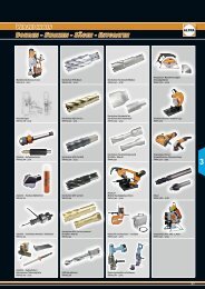
APunching – Bending – Cutting<br />
B Drilling<br />
– punching – cutting – deburring<br />
Alfred Raith GmbH • 2. Industriestraße 10 • DE - 68766 Hockenheim • P. O. Box 1667 • DE - 68759 Hockenheim<br />
Phone +49 (0) 62 05/30 51 - 0 • Fax +49 (0) 62 05/30 51 - 135 • Internet: www.alfra.de • E-mail: export@alfra.de<br />
04/2012