CPT International 02/2022

You also want an ePaper? Increase the reach of your titles
YUMPU automatically turns print PDFs into web optimized ePapers that Google loves.
www.cpt-international.com<br />
WITH SUPPLIERS GUIDE<br />
June<br />
2<strong>02</strong>2<br />
CASTING<br />
PLANT AND TECHNOLOGY<br />
INTERNATIONAL<br />
2<br />
The great<br />
Freedom<br />
Design freedom, free of emissions.<br />
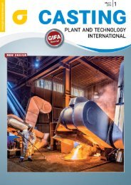
Inorganic binders for 3D printing sand<br />
molds and cores.
WIR FREUEN UNS AUF IHREN BESUCH<br />
IN HALLE 9, STAND 9-618<br />
WE LOOK FORWARD TO YOUR VISIT<br />
IN HALL 9, BOOTH 9-618<br />
08. – 10.06.2<strong>02</strong>2 in Nürnberg/Nuremberg<br />
DVS Media GmbH • Aachener Straße 172 • 4<strong>02</strong>23 Düsseldorf<br />
P +49 2 11 15 91-142 • F +49 2 11 15 91-150 • anzeigen@dvs-media.info • www.dvs-media.eu
EDITORIAL<br />
The green foundry is on the<br />
way<br />
Ever-harsher environmental and health & safety at work regulations, greater<br />
demands from original equipment manufacturers (OEMs) regarding sustainability<br />
of the supply chain, and a generally growing awareness of green topics:<br />
the foundry industry faces a turning point. So it is only logical that suppliers<br />
also look into sustainable environmentally friendly products. In this issue you<br />
can read about the latest developments on the path to the green foundry.<br />
Photo: BDG<br />
Jan Kretzmann<br />
Editor-in-chief<br />
e-mail: jan.kretzmann@bdguss.de<br />
Föhl, a German specialist in zinc<br />
die-casting, offers an ecological<br />
alternative to conventional hot<br />
chamber casting with its hot runner technology,<br />
which not only reduces the need<br />
for material and energy, but also enables<br />
the production of entirely new shapes<br />
with zinc. As an energy-intensive production<br />
company, Föhl is particularly aware<br />
of its responsibility and has already been<br />
operating CO2-neutrally since 2<strong>02</strong>0. A<br />
clear incentive for us to take a closer<br />
look at this progressive process.<br />
Sustainability is also the focus of our<br />
second die-casting topic. ExOne from<br />
southern Germany are experts in 3D<br />
printing applications, with an awareness<br />
of environmentally friendly technologies<br />
– inorganic 3D printing promises<br />
considerably lower BTEX, CO2, odor<br />
and noise emissions, as well as improved<br />
working conditions. The system can<br />
be integrated in existing plants, and<br />
enables a step-by-step introduction of<br />
these modern and sustainable processes<br />
for mold and core production.<br />
Our article on new types of furan<br />
resins is also all about environmental<br />
protection. Furan binders – actually ‘old<br />
hat’, having been introduced as long<br />
ago as the late 1950s – could be classified<br />
as the first real NoBake binders due<br />
to their ability to self-harden under acidic<br />
conditions at ambient temperature<br />
(without heat). They are used to produce<br />
all types of metal castings of all<br />
sizes – from small components to large<br />
products, such as the rotor hubs of wind<br />
turbines. In this regard, ASK Chemicals<br />
has now developed a new generation<br />
of environmentally friendly furan resins<br />
with a low content of free furfuryl alcohol<br />
(without the skull-and-crossbones<br />
label), whose performance is comparable<br />
with standard furan resins.<br />
Our article about the cylinder heads<br />
of the current Porsche naturally aspirated<br />
engine may well be a treat for automotive<br />
enthusiasts. Compared to its<br />
predecessor, the 718 Boxster / Cayman<br />
GTS 4.0 liter, Spyder and Cayman GT4<br />
series of engines make greater stress<br />
and weight demands on this fundamental<br />
component. These demands are<br />
countered with a special thin-walled<br />
casting design that is reliably reproducible<br />
with permanent molds using the<br />
Rotacast process. Find out how Porsche<br />
and Nemak have mastered this challenge<br />
to implement the centerpiece of<br />
this powerful high-tech engine.<br />
One Swedish-Thai joint venture is a<br />
project for the complete simulation of<br />
unheated, laser-controlled stopper casting<br />
implemented by pourtech AB (from<br />
Göteborg) and M5 Engineering (based<br />
in Bangkok). In recent months, the two<br />
companies have simulated in detail the<br />
technological basis for unheated casting<br />
with the help of Magma casting simulation<br />
– creating optimization potentials.<br />
Have a good read!<br />
CASTING PLANT & TECHNOLOGY 2/2<strong>02</strong>2 3
CONTENTS<br />
FEATURES<br />
6 DIE CASTING<br />
Gradual Progress to the green foundry<br />
Inorganic 3D printing can be integrated into the<br />
existing environment and enables modern and<br />
sustainable mold and core production.<br />
Andreas Müller<br />
8 DIE CASTING<br />
Hot runner technology enables<br />
casting of filigree geometries<br />
Zinc die-casting specialist Föhl offers an<br />
environmentally friendly alternative to<br />
conventional hot-chamber die-casting.<br />
Nadine Konstanty<br />
12 COREMAKING<br />
The world‘s largest coremaking engine<br />
Laempe Mössner Sinto has assembled the world’s<br />
largest core shooting machine, weighing over 300<br />
tonnes.<br />
Thomas Doriath<br />
PROCESS<br />
Structural components<br />
for automotive<br />
industrie are a key<br />
product for die<br />
casters.<br />
CASTING<br />
Porsche Boxster<br />
models with new<br />
thin-walled cylinder<br />
heads.<br />
14 CASTING<br />
Conserve resources and protect the<br />
environment with Magmasoft<br />
How Brazilian faucet and shower specialist Docol<br />
actively contributes to environmental protection.<br />
Pia Sonntag<br />
www.cpt-international.com<br />
June<br />
WITH SUPPLIERS GUIDE 2<strong>02</strong>2<br />
CASTING<br />
2<br />
PLANT AND TECHNOLOGY<br />
INTERNATIONAL<br />
The great<br />
Freedom<br />
Design freedom, free of emissions.<br />
Inorganic binders for 3D printing sand<br />
molds and cores.<br />
Cover-Photo:<br />
ExOne GmbH<br />
Daimlerstrasse 22, 86368 Gersthofen,<br />
Germany europe@exone.com<br />
www.exone.com<br />
COMPANY<br />
Attention to more<br />
than the mandatory<br />
standards is necessary<br />
when buying the<br />
right protective<br />
clothing.<br />
ExOne is a worldwide leading manufacturer for powerful<br />
3D printers since 1995. The products solve toughest<br />
problems and enable world-changing innovations.<br />
4
CONTENTS<br />
16 CASTING<br />
Complex casting without a melt<br />
Find out about the hybrid gel casting process.<br />
Sebastian Riecker<br />
19 PROCESS<br />
The right release agent for greater<br />
efficiency and sustainability<br />
Increasing demand from differing sectors involves<br />
new requirements for die-casters regarding component<br />
quality and process optimization. Selecting the<br />
right release agent can help achieve new goals.<br />
John Belyk, Darko Tomazic, Albrecht Vogel<br />
22 PROCESS<br />
Automation trends in material testing<br />
Material tests are increasing being automated.<br />
Find out about new possibilities.<br />
Wolfgang Mörsch<br />
25 PROCESS<br />
High sorting efficiency despite impurities<br />
A new type of complete plant with three<br />
operating modes filters recycling aluminum<br />
from difficult input material.<br />
Sophie Kesy<br />
28 PROCESS<br />
Consistent and agile exploitation<br />
of business opportunities<br />
Using chances in distribution effectively.<br />
Peter Schreiber<br />
36 CASTING<br />
Eco-friendly furan resigns<br />
A new generation of eco-friendly furan resins with<br />
low furfuryl alcohol and standard performance.<br />
Nicolas A. Riensch, Thomas Krey, Carolin Wallenhorst<br />
40 CASTING<br />
Thin-walled Porsche Boxer cylinder heads<br />
How Porsche and Nemak used the Rotacast process<br />
for a new Boxer engine generation.<br />
Günter Vogelezang, Bernhard Stauder<br />
45 CASTING<br />
PROCESS<br />
In the fully<br />
automated testing<br />
laboratory, AGVs<br />
transport the samples<br />
between the sample<br />
preparation area and<br />
the testing machines.<br />
Pouring process simulation<br />
How pour-tech AB and M5 engineering simulated<br />
the unheated pouring and created potential for optimization.<br />
Michael Colditz Sävedalen, Loedwilat Thipramongkhon,<br />
Chindanai Challinak<br />
COLUMNS<br />
3 EDITORIAL<br />
49 NEWS IN BRIEF<br />
54 SUPPLIERS GUIDE<br />
62 PREVIEW/IMPRINT<br />
CASTING PLANT & TECHNOLOGY 2/2<strong>02</strong>2 5
plex cores and molds that offer designers<br />
considerably greater freedoms than<br />
conventional processes. It also offers<br />
the direct manufacturing of components<br />
in almost any numbers, from prototypes<br />
to serial production. It is thus<br />
competitive compared to traditional<br />
mold production, and an opportunity to<br />
strengthen a foundry’s competitive<br />
position by expanding its portfolio.<br />
Sustainable chain<br />
Inorganic binders are increasingly being<br />
used for the 3D printing of cores and<br />
molds. Technology leader ExOne uses a<br />
water-based, alkali-silicate binder,<br />
S-Max ® Pro, for the inorganic serial production<br />
of sand cores. The modular system<br />
consists of the S-Max Pro Sand 3D<br />
printer with a Siemens PLC control system,<br />
a microwave station, an automated<br />
de-sanding station, a jobbox and<br />
the appropriate conveyor system. The<br />
expensive ventilation system, essential<br />
for removing toxic emissions when<br />
organic binders are used, is no longer<br />
necessary. Depending on the core’s volume<br />
and geometry, after printing it is<br />
dried and hardened in the microwave<br />
for a period ranging from a few minutes<br />
to about 45 minutes and then<br />
automatically de-sanded in a fraction of<br />
the time otherwise required. The loose<br />
sand is recycled for subsequent printing<br />
processes, ensuring sustainability<br />
throughout the chain. After finishing,<br />
the cores can be stored dry or immediately<br />
inserted in the mold and used for<br />
casting. The technical casting properties<br />
and strength of the cores can be controlled<br />
via the gating system.<br />
Process optimization<br />
by linking up to four<br />
S-Max Pro Sand 3D<br />
printers with one<br />
automatic de-sanding<br />
station.<br />
individual components in the periphery<br />
mean that the plant can grow over time<br />
and adapt to changing throughput. The<br />
microwave and de-sanding stations can<br />
each be combined with up to four<br />
S-Max Pro Sand 3D printers, while core<br />
removal, fine de-sanding and quality<br />
assurance can practically be automated<br />
as desired using robots. The system thus<br />
offers a relatively straightforward entry<br />
to the world of inorganic binders, and<br />
the possibility of gradually migrating to<br />
environmentally friendly processes.<br />
Physical limits are being raised<br />
Organic binders have a considerably<br />
greater market share worldwide than<br />
inorganic binders. This is not solely due<br />
to this process being much younger<br />
than others. Inorganic binders are (still)<br />
not suitable for every application. Heat<br />
behavior above 900°C – generally<br />
uncritical for aluminum castings – is particularly<br />
problematic for processing<br />
steel and sets physical limits. These cannot<br />
be ignored, but are constantly<br />
being raised. Like many institutes and<br />
researchers, ExOne is also working on<br />
preventing vitrification at higher temperatures<br />
by using admixtures, among<br />
other things. At present, however, each<br />
foundry must individually ask itself<br />
whether the process of inorganic binder<br />
jetting matches its particular product<br />
portfolio – yet. Early adopters, companies<br />
with a view of the future of<br />
foundry technology that want to test<br />
whether they can already use the technology,<br />
can try it out in pilot projects<br />
conducted in collaboration with ExOne.<br />
Organic binders also have<br />
green potential<br />
Organic binders, however, have not yet<br />
exhausted their sustainability potentials.<br />
ExOne has already achieved ideal<br />
results in the high-temperature range<br />
with modified furan binders, for example,<br />
that are free from resorcinol and<br />
BPA. Inorganic binders will be available<br />
for all temperature ranges in the<br />
medium and long term. Until then,<br />
foundries should follow a twin-track<br />
approach: if possible, the inorganic<br />
binder and S-Max Pro Sand from ExOne<br />
is to be preferred for light metal casting<br />
at temperatures of up to 900°C. In addition,<br />
the low-classification furan binders<br />
from ExOne provide an organic but<br />
environmentally friendly and safe alternative<br />
to conventional materials.<br />
www.exone.com<br />
System technology that grows as<br />
required<br />
The system solution’s high level of modularity<br />
and the good performance of<br />
Automatic de-sanding and unpacking of complex mold geometries.<br />
CASTING PLANT & TECHNOLOGY 2/2<strong>02</strong>2 7
DIE CASTING<br />
Thomas Herper from Föhl explains hot runner technology using a casting as an example.<br />
Zinc die-casting<br />
Hot runner technology enables<br />
casting of filigree geometries<br />
Föhl, the zinc die-casting specialist based in Baden-Württemberg, offers an environmentally<br />
friendly alternative to conventional hot-chamber die-casting with its hot runner<br />
technology, which not only reduces material and energy consumption, but also enables<br />
completely new shapes with zinc.<br />
By Nadine Konstanty<br />
Photos and Graphics: FOEHL<br />
If desired, the process can be carried<br />
out without a gating system or with<br />
a greatly reduced one, and enables<br />
the casting of geometries with wall<br />
thicknesses of just 0.3 mm and part<br />
weights of below 2 g. Compared to<br />
conventional processes, it is characterized<br />
by greater component quality<br />
due to fewer air inclusions and a high<br />
density of > 650 g/cm3. Finishing<br />
requirements are also considerably<br />
reduced.<br />
Lived sustainability ensures technological<br />
lead<br />
Föhl is well aware of its responsibilities<br />
– particularly as an energy-intensive<br />
production company – and has already<br />
been operating CO2-neutrally since<br />
8
35,00<br />
Quantity CO2 per unit<br />
HOT RUNNER<br />
30,00<br />
25,00<br />
CONVENTIONAL<br />
HOT RUNNER<br />
Reduction of CO 2<br />
emissions by about 80%<br />
Quantity CO2 in g<br />
20,00<br />
15,00<br />
10,00<br />
5,00<br />
0,00<br />
in g<br />
in g<br />
At Föhl<br />
with green electricity so<br />
CO 2<br />
emissions at<br />
ZERO<br />
Quantity CO2 generated in Germany with electricity mix / unit<br />
Quantity CO 2<br />
generated CNG / unit<br />
2<strong>02</strong>0. Environmentally friendly reorganization<br />
measures, renewable energies,<br />
intensive development work, newly<br />
planted forests, and energy scouts all go<br />
hand-in-hand at the family-owned company<br />
in Rudersberg. Sustainable thinking<br />
also has a major influence on development.<br />
So, among other things,<br />
hot-runner processes – developed<br />
in-house – make a contribution towards<br />
reducing the use of energy and materials<br />
in the firm’s core technology of casting.<br />
The proportion of return materials<br />
has been reduced by up to 50%, for<br />
example. Moreover, the lower levels of<br />
sprue means that up to twice as many<br />
parts per shot can be cast given the<br />
same machine size. This results in less<br />
material consumption, more rapid<br />
throughput, and lower energy costs.<br />
“Our aim was to double the number<br />
of parts produced on the same machine.<br />
This has been achieved with new technology,<br />
in that we reduce the runner<br />
and gating to a minimum or do without<br />
any gating at all, and correspondingly<br />
introduce less air into our mold. A positive<br />
side effect of this is that it minimizes<br />
problematic inclusions, which can<br />
cause weak points. Last but not least,<br />
the environment profits because energy<br />
consumption is lower and there is less<br />
return material because of the doubling<br />
of the cavities,” explains Thomas Herper,<br />
responsible for Technical Sales at<br />
Föhl.<br />
Fig. 2: Part of window fitting made with 32-fold hot runner design.<br />
Hot runner nozzle for improved<br />
quality<br />
The development of a new hot runner<br />
nozzle for zinc die-casting, similar to<br />
the hot runner technology familiar from<br />
plastic injection molding, provides the<br />
basis for sprue-free casting. During the<br />
process, the melt is fed directly into the<br />
a<br />
b<br />
Fig. 3a: Motor covers for ventilators produced using hot runner technology.<br />
Fig. 3b: Motor cover for ventilator produced conventionally.<br />
CASTING PLANT & TECHNOLOGY 2/2<strong>02</strong>2 9
DIE CASTING<br />
cavity via the hot runner nozzle. So<br />
parts are zinc die-cast without, or with<br />
far less, sprue formation, which considerably<br />
reduces the air inclusions in the<br />
product due to the lack of gating. Correspondingly,<br />
even with very low wall<br />
thicknesses of from 0.3 mm, parts now<br />
only exhibit minimal porosity – about<br />
2.3%. The use of hot runner nozzles<br />
allows the casting of more complex<br />
shapes that would not be possible with<br />
conventional processes. The use of several<br />
hot runner nozzles also offers the<br />
advantage of multiple mold occupancy.<br />
The use of several nozzles for one component<br />
increases the material quantity<br />
that is introduced into the mold cavity<br />
in the same time. This supports homogeneous<br />
cooling of the cast product<br />
and prevents shrinkage cavities or<br />
stresses.<br />
The positioning of the hot runner<br />
nozzle directly on the component permits<br />
pinpoint feeding-in of the material.<br />
Thus, like with pinpoint gating<br />
during plastic injection molding, the<br />
flow paths into the tool and kept short<br />
and regular. Round castings can now<br />
also be implemented very well because<br />
no flattening is required for any sectioning<br />
of the gating system. The distances<br />
travelled by the material into the<br />
cavity – particularly at the center of the<br />
component – are short. Thus the material<br />
flow into the shaping area is no longer<br />
the diameter of the product to be<br />
manufactured, but the radius. The lack<br />
of a gating system also creates space for<br />
additional cavities on the machine and<br />
reduces follow-up processes.<br />
Serial production for automotive<br />
and industrial applications<br />
Fig. 4a: Conventional process with 8 castings per mold vs. hot runner technology with 16-fold<br />
mold design.<br />
Fig. 4b: Hot runner technology cuts CO2 emissions by about 80% compared to conventional<br />
casting.<br />
The proportion of hot runner products<br />
in serial production at Föhl is steadily<br />
increasing – so high unit numbers have<br />
become established as the norm. Other<br />
projects are taking place during the<br />
design and sample phases. Whereby the<br />
figures compared to conventional production<br />
speak for themselves, as all<br />
aspects yield optimized results. In a case<br />
study on a retaining washer for automotive<br />
construction with dimensions of<br />
ø20 mm x 3.4 mm and a component<br />
weight of 6 g, a saving of 40% in return<br />
a<br />
b<br />
material was achieved using a 16-fold<br />
mold design – doubling the cavities<br />
using the same machine and with density<br />
improved by 1.22% for the 6.5 m.<br />
units currently produced each year.<br />
www.foehl.de/en<br />
10
The international technical journal<br />
WE ACCOMPANY THE FUTURE OF<br />
THE INTERNATIONAL STEEL INDUSTRY<br />
steel production<br />
application technology<br />
innovation + management<br />
processing<br />
READ STEEL + TECHNOLOGY REGULARLY.<br />
SUBSCRIBE NOW AT WWW.DVS-MEDIA.EU/EN/MAGAZINES/STAHL
COREMAKING<br />
Photos: Laempe Mössner Sinto GmbH<br />
Laempe LHL200-1700<br />
Laempe employees pose with the new flagship, the<br />
LHL200-1700. The picture gives an impression of the<br />
facility’s enormous size.<br />
The world’s largest core shooter<br />
Laempe Mössner Sinto has assembled the world’s largest core shooting machine<br />
at a works in Magdeburg (Saxony-Anhalt). The customer is a leading Chinese engine<br />
manufacturer.<br />
By Thomas Doriath<br />
Laempe constructed this automated<br />
core shooter – which exceeds all<br />
previous dimensions – for a large<br />
Chinese engine producer. The Laempe<br />
machine will be used in Weifang, China,<br />
to produce cores for casting ships’<br />
engines. The LHL200-1700, as the<br />
machine is officially called, has been put<br />
into operation with the customer,<br />
shipped out and is currently being set<br />
up at destination.<br />
The LHL200-1700 will be installed<br />
and operated in China. The heavyweight<br />
among core shooters is an<br />
impressive giant – eleven meters tall, 16<br />
meters long and 30 meters wide, with a<br />
weight of 300 tonnes. The dimensions<br />
of the core box are the same as those of<br />
a standard Laempe core shooter. The<br />
shooting volume of the LHL200-1700 is<br />
1,700 liters with core box dimensions of<br />
3 x 3 meters and a tool weight of up to<br />
30 tonnes – also a new record in the<br />
foundry industry. Consequently, the<br />
cores also set new standards: they can<br />
weigh up to 2.5 tonnes, and the customer<br />
will use them in their foundry as<br />
parts of a mold for ships’ engines.<br />
The core shooter was designed in<br />
Schopfheim, Baden, by the research and<br />
development department of Laempe<br />
Mössner Sinto GmbH, and produced in<br />
Meitzendorf and, since the machine<br />
12
dimensions would have exceeded the<br />
possibilities of Laempe’s own production<br />
hall, the record LHL was assembled<br />
at SKET GmbH (Schwermaschinenkombinat<br />
Ernst Thälmann) in Magdeburg.<br />
“The LHL200-1700 is a milestone for<br />
us because it shows that we are the perfect<br />
partner for foundries when it<br />
comes to the construction of customized<br />
machines. This major project was<br />
implemented with excellent collaboration<br />
between all the departments at<br />
our three locations in Meitzendorf,<br />
Schopfheim and Mannheim. This<br />
impressively demonstrates how<br />
cross-departmental and cross-site cooperation<br />
can lead to top performance in<br />
the interests of our customers,” says<br />
Rudolf Wintgens, Managing Director of<br />
Laempe Mössner Sinto GmbH. Laempe<br />
employs around 240 people at its headquarters<br />
in Meitzendorf, about 90<br />
employees in Schopfheim and eleven in<br />
Mannheim.<br />
Delivery of the LHL200-1700 is the<br />
largest component of the customer’s<br />
order. The company from the Shandong<br />
province produces engines, among<br />
other things, and employs more than<br />
50,000 people.<br />
www.laempe.com<br />
On target.<br />
IR Cameras. Pyrometers. Accessories.<br />
Software. We measure temperature<br />
non-contact from –50 °C to +3000 °C.<br />
Visit: www.optris.global<br />
Our affordable and fixed installed<br />
longwave and shortwave IR cameras<br />
with analog/digital outputs are ideal<br />
for industrial and R&D applications.<br />
Rudolf Wintgens, Managing Director of Laempe Mössner Sinto, standing next to a<br />
produced core.<br />
when temperature matters
CASTING DIE CASTING<br />
Numerical simulation<br />
Conserve resources and protect<br />
the environment with Magmasoft<br />
For Brazilian faucet and shower specialist Docol, sustainability is an integral part of their<br />
corporate policy. To actively contribute to environmental protection in this area, the<br />
company decided to use numerical simulation with Magmasoft.<br />
By Pia Sonntag, Aachen<br />
Photos: Magmasoft<br />
The following example shows how<br />
virtual simulation enabled Docol<br />
to reduce the scrap rate in the<br />
production of a single-lever mixer.<br />
Figure 1a shows the „Lift“ mixer, whose<br />
body is cast from a copper-zinc alloy in<br />
a low-pressure casting process. The cast<br />
part systematically showed hot tears in<br />
the rear area, which affected the surface<br />
of the part, (Fig. 1c). Hot tears<br />
occur at the end of solidification,<br />
usually run along grain boundaries, and<br />
the fracture surface is intercrystallin.<br />
This formation mechanism can often be<br />
recognized from the shape of the crack,<br />
which is „jagged“ in the finished part,<br />
(Fig. 1d).<br />
In order to find a solution as quickly<br />
as possible, Docol contacted Magma<br />
with the question: What is the optimal<br />
way to detect the factors influencing<br />
the tendency for hot tears? The objective<br />
was to reduce scrap by 50% and<br />
thus reduce material consumption. At<br />
the same time, the lead time in production<br />
should be shortened systematically.<br />
Fig. 2 shows the initial situation:<br />
There is still partially solidified melt in<br />
the rear area of the component, while<br />
the material outside is already comple-<br />
14
Fig. 1: „Lift“-single-lever<br />
mixer (a),<br />
Magmasoft-model<br />
(b) and occuring casting<br />
defect (c) as<br />
well as location of<br />
heat tear (d).<br />
tely solidified. This means that here<br />
even slight stresses are sufficient to<br />
form ductile deformations or cracks.<br />
The entire height of the single-lever<br />
mixer shows increased strain rates in<br />
areas that have not yet solidified ((Fig.<br />
2a) (Fig. 2b). This causes a high hot tear<br />
tendency (Fig. 2c).<br />
Shrinkage porosity remains stable<br />
Based on this results analysis, Docol set<br />
up a virtual test plan with Magmasoft to<br />
investigate the influence of geometry<br />
variations on the tendency for hot tears.<br />
The geometry was parameterized at the<br />
gate (thickness and radius) and within<br />
the casting (wall thickness). However, it<br />
was important to ensure that the<br />
change in casting and process parameters<br />
did not lead to an increased shrinkage<br />
porosity in the critical area. The<br />
evaluation of the 25 different designs<br />
calculated by Magmasoft showed that,<br />
with regard to hot tears, design 20 is the<br />
optimal variant: lower strain rates<br />
(represented by the result ‚Max Principal<br />
Strain Rate‘) as well as reduced fraction<br />
liquid (‚Fraction Liquid‘) in the investigated<br />
area. Figure 3 compares the results<br />
of the original and the optimized version<br />
of the project. The hot tear tendency<br />
decreases significantly and the<br />
shrinkage porosity remains stable at a<br />
low level. Mission accomplished.<br />
The change of geometry reduced<br />
scrap by 70% and weight by 8%. In<br />
addition to the robust production as<br />
well as the desired quality requirements,<br />
there were further advantages<br />
with regard to sustainability: the<br />
consumption and the disposal of sand<br />
and resins were minimized. In addition,<br />
the consumption of water, electrical<br />
energy, abrasives and liquid gas was<br />
reduced. As it turns out, protecting<br />
nature and being environmentally conscious<br />
can be so easy when you have the<br />
right tools.<br />
www.magmasoft.de/en/<br />
Fig. 2: result analysis of the initial situation: (a) fraction liquid ‚Fraction Liquid‘, (b) strain rates<br />
‚Max. Principal Strain Rate‘, (c) Hot Tear Tendency ‚Hot Tear‘.<br />
Fig. 3: Comparison of the initial and the optimized version: The optimized version shows a lower fraction liquid ((a) vs. (c)) as well as lower<br />
strain rates ((b) vs. (d)).<br />
CASTING PLANT & TECHNOLOGY 2/2<strong>02</strong>2 15
CASTING<br />
Photos and graphics: FRAUNHOFER IFAM<br />
Gel casting<br />
From the suspension to a dense metal component<br />
in just a few steps.<br />
Producing complex castings<br />
without a melt<br />
It is impossible to burn one’s fingers here. No metal is melted for subsequent casting<br />
when the hybrid gel casting process is used. This is a suspension casting technique that<br />
permits the production of complex metal components with internal channels and thus<br />
achieves the structural freedom of additive processes. The process chain is equally suitable<br />
for the production of components made of metals or ceramics.<br />
By Sebastian Riecker, Dresden<br />
The gel casting hybrid suspension<br />
process runs at moderate temperatures<br />
and makes very low<br />
demands of the molds. The newly<br />
developed metal powder suspension –<br />
which mainly consists of water, powdered<br />
metal (generally greater than 55<br />
percent of volume), and a variety of<br />
organic additives – is at the heart of this<br />
innovative process presented by the<br />
researchers of the Fraunhofer Institute<br />
for Manufacturing Technology and<br />
Advanced Materials (IFAM) in Dresden.<br />
The suspension is liquid when heated to<br />
about 40 - 70°C, and hardens into a<br />
flexible but solid gel when cooled to<br />
room temperature.<br />
The process<br />
The following process steps are necessary<br />
to produce metallic components<br />
using the gel casting technique (Fig. 1):<br />
FRAUNHOFER IFAM, DRESDEN<br />
Mold production<br />
As with classic metal casting, molds are<br />
required. But, because of the low thermal<br />
and mechanical stresses in suspension<br />
casting, these can be made of plastic,<br />
wax, metal, or even other materials<br />
such as wood. A simple approach is the<br />
production of plastic molds from a 3D<br />
The Fraunhofer Institute for Manufacturing Technology and Advanced Materials<br />
(IFAM) in Dresden is one of the world’s leading research institutions in the field<br />
of powder metallurgical technologies, as well as sinter and composite materials<br />
for functional applications. It carries out fundamental applied research to<br />
develop solution-oriented materials and technologies. Its activities range from<br />
the industrial implementation of research results to the production of prototype<br />
components and their transfer to industrial use. Developments take place along<br />
the entire process chain. In the field of additive manufacturing, powder-based<br />
selective electron beam melting (SEBM) and five sinter-based processes are currently<br />
being further developed. In addition to the gel casting process described<br />
above, the sinter-based AM processes include 3D screen printing, fused filament<br />
fabrication (FFF), lithography-based metal manufacturing (LMM) and the MoldJet<br />
process. All technological expertise in this area is consolidated in the ICAM (Innovation<br />
Center Additive Manufacturing) of the Fraunhofer IFAM in Dresden.<br />
16
Polymer<br />
Mold Production<br />
Casting Process<br />
Demolding<br />
1<br />
Heat Treatment<br />
Fig. 1: The individual process steps in gel casting based on an example: a) mold production, b) filling with suspension, c) removal of the<br />
hardened component from the mold, d) heat treatment.<br />
printer via the so-called fused filament<br />
fabrication (FFF) process.<br />
Suspension casting<br />
After heating to 40 - 70°C, the suspension<br />
has a viscosity similar to that of varnish<br />
and can be inserted into the mold.<br />
This can be carried out without pressure<br />
in open or closed molds, or supported<br />
by pressure with vacuum or positive<br />
pressure.<br />
Removal from the mold<br />
Depending on the complexity of the<br />
component, the castings can be directly<br />
removed from the mold after cooling<br />
and meshing of the binder (Fig. 2) or<br />
the mold can be completely dissolved in<br />
a solvent bath. Complex undercut structures<br />
and internal channels can be<br />
achieved by using a lost-mold technique<br />
and dissolution in a solvent bath.<br />
Heat treatment<br />
The demolded component still consists<br />
of metal powder and binder (adhesive)<br />
in the form of a so-called green part.<br />
After pre-drying, the organic components<br />
are now burnt out in a furnace<br />
process (thermal de-binding) and the<br />
still-porous green part transformed into<br />
a dense metal component at high temperatures<br />
(sintering).<br />
FeSi6.5, FeCo50 or nickel-based alloys<br />
such as Inconel 718 (2.4668) and Inconel<br />
625 (2.4856); light metal alloys such as<br />
Ti-6Al-4V (3.7164); or even pure copper<br />
and copper alloys, refractory metals and<br />
alloys, as well as hard metals and composite<br />
materials. Up to now the process<br />
has been successfully tested on tool<br />
steel M2, stainless steel 316L, hard<br />
metal (tungsten carbide), copper-diamond<br />
and Ti-6Al-4V.<br />
The components exhibit typical sinter<br />
structures and are somewhat finely<br />
grained. The structure naturally<br />
depends on the material and the heat<br />
treatment, and can be precisely<br />
adjusted via the furnace process, if<br />
required. As a result of the high sintering<br />
temperatures of about 80% of the<br />
melting temperature, the components<br />
come out of the furnace stress-free and<br />
have a very finely distributed residual<br />
porosity of typically 0.1 - 4%. If the<br />
demands made of the material are particularly<br />
high, the components can be<br />
completely re-pressed with hot isostatic<br />
pressing. Whereby the component<br />
properties are comparable to those of<br />
components produced using metal<br />
powder injection molding. For stainless<br />
steel, for example, a tensile strength of<br />
514 MPa and a uniform elongation of<br />
41% was achieved. The material specification<br />
for 1.4404 is a tensile strength of<br />
500 - 700 MPa and a breaking elongation<br />
of 30 - 40% [1].<br />
Geometries<br />
The components that can be manufactured<br />
mainly depend on the geometries<br />
that can be produced as a mold, and<br />
whether these can be filled without<br />
faults. The suspension remains liquid for<br />
several minutes so that a too-rapid<br />
hardening is generally no problem<br />
during pouring. Moreover, there is no<br />
loss of volume during hardening (meshing),<br />
so that the shrinkage cavities<br />
caused by thermal shrinkage are also<br />
not relevant here. In contrast to this,<br />
plastic molds are not permeable to air,<br />
so the prevention of gas pores in the<br />
corners of the molds requires a suitable<br />
casting process or air vents.<br />
When one takes these aspects into<br />
account, wall thicknesses of about 0.3<br />
mm to > 40 mm can be achieved in a<br />
component. Fine structures or a particularly<br />
smooth mold surface are thereby<br />
reflected in great detail. For example,<br />
printed molds can be smoothed using<br />
solvent before the casting process to<br />
avoid subsequent complicated finishing<br />
of the metal component (Fig. 3). The<br />
Materials and properties<br />
The process route via the green part<br />
made of metal powder and the sintering<br />
step in the furnace is already familiar<br />
from other processes such as ‘press &<br />
sinter’, metal injection molding (MIM),<br />
or sinter-based additive manufacturing<br />
(AM). So a wide range of materials is<br />
already available that are, in principle,<br />
also suitable for processing via the gel<br />
casting process. Typical examples of<br />
these include various iron-based alloys<br />
such as the stainless steels 316L (1.4404)<br />
and 17-4PH (1.4542); working steels<br />
such as M2 (1.3343), D2 (1.2379) or H13<br />
(1.2344); magnetic alloys such as<br />
Fig. 2: Direct<br />
removal of the<br />
so-called green part<br />
from a divided,<br />
3D-printed plastic<br />
mold (component<br />
from input picture).<br />
CASTING PLANT & TECHNOLOGY 2/2<strong>02</strong>2 17
CASTING<br />
Fig. 3: Complex<br />
mathematical<br />
‘gyroid’ structure<br />
made of stainless<br />
steel 316L, produced<br />
using a plastic<br />
3D-printed mold<br />
smoothed in a solvent<br />
bath.<br />
sintered parts have a correspondingly<br />
high surface quality when milled molds<br />
are used. In addition, internal channels<br />
and strong undercuts can be implemented<br />
by using lost molds. Fig. 4 shows<br />
part of a calibration tool for plastic<br />
extrusion. The component was made of<br />
M2, weighs about 800 g, and contains<br />
both vacuum and cooling channels.<br />
The weight of sintered components<br />
is typically below 500 g, though in<br />
exceptional cases – and depending on<br />
the material and geometry – weights of<br />
up to 5 kg are also possible. Users of the<br />
gel casting process have many possibilities<br />
for individually adapting the process<br />
because both mold production and<br />
the casting process can be very specifically<br />
fashioned. Individual single parts<br />
can be produced using a mold made via<br />
additive manufacturing, while small<br />
and medium-sized series can be implemented<br />
with reusable permanent<br />
molds. Depending on the component<br />
geometry, mass production is conceivable<br />
with filling on a conveyor belt.<br />
If certain component features cannot<br />
be generated directly via the casting<br />
process, there is still the possibility<br />
of mechanically processing the green<br />
part, which consists of powder and<br />
binder, before sintering. Whereby the<br />
strength of the green part is similar to<br />
that of plaster, and the cutting forces<br />
during processing are very low – so<br />
work can take place without coolant.<br />
Whereby very fine details can be<br />
achieved with good surface quality. In a<br />
trial geometry (Fig. 5), pins with a<br />
length of 2 mm and a diameter of 0.4<br />
mm could be carved out with multiple<br />
reproducibility and fault-free. The<br />
milled structure could then be converted<br />
to a dense component without<br />
deformation. Whether a part can be<br />
produced depends on many factors that<br />
must be individually assessed. The limits<br />
of what is technically possible are constantly<br />
expanding because the process is<br />
continuously developing.<br />
Summary<br />
The gel casting process is a suspension<br />
casting technique that was developed<br />
for the production of complex metal<br />
parts. It requires no liquid metal and<br />
can be implemented with many different<br />
alloys, pure metals or composite<br />
materials. The use of watery suspensions<br />
at low temperatures, and the<br />
great freedom permitted during production<br />
of the mold and during the<br />
casting process, make gel casting very<br />
flexible and individually adaptable.<br />
www.ifam.fraunhofer.de/gelcasting<br />
Further information:<br />
The Fraunhofer Institute for Manufacturing<br />
Technology and Advanced<br />
Materials (IFAM)<br />
Dr.-Ing. Sebastian Riecker<br />
Winterbergstrasse 28<br />
D-01277 Dresden<br />
Germany<br />
Tel.: +49 (0)351 2537-429<br />
e-mail: Sebastian.riecker@ifam-dd.<br />
fraunhofer.de<br />
Literature:<br />
[1] Wegst, Claus W, & Wegst, Micah,<br />
Stahlschlüssel-Taschenbuch, 22. Aufl.<br />
2010, Verlag Stahlschlüssel Wegst<br />
GmbH, Marbach.<br />
Fig. 4: Part of a calibration tool with internal<br />
vacuum and cooling channels: a) CAD sectional<br />
view and b) sintered component made of<br />
working steel M2. The mold was 3D-printed,<br />
the component could subsequently be<br />
removed from the mold in an acetone bath.<br />
Fig. 5: Test component with fine pins (D = 0.4 mm, H = 2 mm) milled and sintered from<br />
the green body (consisting of powder and binder).<br />
18
PROCESS<br />
Process optimization<br />
The right release agent for greater<br />
efficiency and sustainability<br />
Increasing demand from differing sectors always involves new requirements for die-casters<br />
regarding component quality and process optimization. As a result, options that<br />
really can be implemented and that are sustainable are required to optimize production<br />
processes to meet rising competitive and costs pressures. Selected releasing agents – proven<br />
to meet the rigorous and demanding requirements in practice – are available to help<br />
reach these goals.<br />
By John Belyk, Darko Tomazic, Albrecht Vogel, Maisach near Munich<br />
Photos and graphics: Chem-Trend<br />
Innovations in die-casting are obvious:<br />
innovative technologies, for example,<br />
promise to increase efficiency during<br />
the production process. New materials,<br />
tools and processes are regularly presented,<br />
and digitalization and the use<br />
of robots promise further improvements<br />
in production. The result: continuous<br />
optimization and increasing component<br />
quality.<br />
Die-casting on the rise<br />
These developments coincide with<br />
changing, though constantly growing,<br />
demand. Whereby the changes in automotive<br />
construction – the key industry<br />
for die-casting, for which a major proportion<br />
of production is destined – are<br />
of particular significance (Fig. 1). No<br />
change in this trend is discernible, even<br />
with the upcoming development<br />
towards alternative drives. On the contrary:<br />
although the drives of e-vehicles<br />
require far fewer cast components that<br />
was the case for combustion engines, a<br />
considerably higher proportion of light<br />
components are required – and carmakers<br />
rely on dependable partners in the<br />
foundry industry for their production.<br />
Whereby die-casting also profits from<br />
positive economic development in<br />
CASTING PLANT & TECHNOLOGY 2/2<strong>02</strong>2 19
PROCESS<br />
Release agents have a key role in the<br />
production process, providing the<br />
die-casting industry with decisive leverage<br />
for positioning itself as future-oriented<br />
and sustainable. Because the<br />
quality properties of advanced release<br />
agents are still underestimated.<br />
Whereby they have a considerable<br />
effect on the quality features of the finished<br />
components – and an intensive<br />
effect on a variety of areas such as process<br />
technology, component function<br />
and, consequently, not least on environmental<br />
impact (Fig. 3). The length of<br />
the service lives of foundry tools is also<br />
dependent on this – apart from the<br />
question of how much mold release<br />
agent is actually required.<br />
Fig. 1: Structural components for vehicle production are a key product for die-casters.<br />
other important segments that are also<br />
significant purchasers of components:<br />
medical technology, for example, or<br />
home electronics, the e-bike segment<br />
and 5G mobile phone technology are<br />
booming.<br />
High competitive pressure and<br />
a poor environmental balance<br />
But even if it sounds paradoxical, the<br />
costs and competitive pressures facing<br />
die-casting companies are increasing<br />
given the constant high demand – particularly<br />
because a large number of<br />
machines are in operation. The benefits<br />
brought about by new technologies<br />
often have an insufficient effect from<br />
an economic point-of-view, because<br />
unexpected situations frequently arise<br />
in the production process and cannot<br />
be handled with the advertised technological<br />
improvements alone. Consider<br />
premature mold wear, high consumption<br />
of compressed air, and rising<br />
energy requirements. These considerable<br />
‘frictional losses’ are caused by the<br />
casting process itself which, in turn, is<br />
characterized by factors such as temperature,<br />
pressure, and the growing<br />
size and complexity of the castings<br />
(Fig. 2). Furthermore, there is a high<br />
consumption of resources in many<br />
cases. Water, for example, is required to<br />
dilute the release agents used. The<br />
more waste water, the higher the costs.<br />
Another challenge facing the sector<br />
is gaining in importance given the topicality<br />
of climate and environmental protection:<br />
the compromises made regarding<br />
sustainability. Not for nothing is the<br />
foundry industry still considered traditional,<br />
energy-intensive and, at least to<br />
some extent, not very environmentally<br />
aware. Though there are already many<br />
companies that show that one can do<br />
better – for example by reducing CO 2<br />
emissions and waste, the need for fresh<br />
water to dilute release agents, or even<br />
the use of release agents in the production<br />
process itself.<br />
Mold release agents with<br />
a key function<br />
Fig. 2: The complexity<br />
of structural<br />
components, in this<br />
case a side member<br />
made of aluminum,<br />
affects the cost-effectiveness<br />
of the<br />
casting process.<br />
Selecting the right release agent<br />
The current generation of release<br />
agents is, by and large, extremely effective,<br />
but there are still very few sustainable<br />
solutions that really offer maximum<br />
process efficiency and<br />
effectiveness. Applications with minimal<br />
quantity requirements are particularly<br />
recommended because a minimum<br />
amount of release agent to protect the<br />
mold is sufficient for optimum results,<br />
applied to the location that is of most<br />
importance for component demolding.<br />
The following criteria are relevant for<br />
deciding on the specific suitable solution:<br />
> A highly efficient release agent concentrate<br />
considerably reduces release<br />
agent consumption because the smallest<br />
of quantities is sufficient to ensure<br />
high demolding performance.<br />
> The application of only a very low<br />
volume of release agent leads to a completely<br />
new type of process and production<br />
technology – for which a variety of<br />
terms already exist on the market, for<br />
example micro-sprays and minimum<br />
quantity sprays.<br />
> A certain expertise is required to<br />
exploit all the advantages. For example,<br />
the use of a special release agent is<br />
required that meets both the demands<br />
of the process (new application technology,<br />
increased mold temperatures) and<br />
the requirements of the component<br />
(OEM delivery specifications).<br />
20
Fig. 3: Advanced release agents have a major<br />
influence on process technology and<br />
environmental impacts.<br />
> The application of minimum<br />
amounts of release agent reduces the<br />
gradients between the tensile stresses<br />
and compressive stresses in the casting<br />
tool, leading to increased tool service<br />
lives.<br />
the costs associated with the die-casting<br />
process. Chem-Trend suggested the<br />
Hera micro-spray to help the company<br />
take a major step forward – regarding<br />
both the technology and the processes.<br />
For this purpose, the customer’s casting<br />
process was analyzed, new paths taken<br />
together, and a future-oriented casting<br />
concept established.<br />
The customer was able to continuously<br />
improve their original results with<br />
the help of a Hera solution presented<br />
ten years ago, in combination with<br />
modern technology for applying the<br />
release agent and optimized mold temperature<br />
control. In particular, Chem-<br />
Trend was able to provide the customer<br />
with fundamental process optimization<br />
support.<br />
The benefits of Hera were immediately<br />
apparent: the cycle time was reduced by<br />
10.5%, leading to a considerable<br />
increase in productivity. Other shortand<br />
long-term benefits included:<br />
> Overall optimization of the production<br />
process.<br />
> Longer mold service lives due to<br />
reduced thermal shock.<br />
> Efficient and reliable spray application<br />
– both for static and mobile spraying.<br />
> Considerably reduced consumption<br />
of compressed air, and much lower use<br />
of fresh water – and almost no waste<br />
water.<br />
> Improved sustainability.<br />
https://chemtrend.com<br />
Watch a video at:<br />
https://bit.ly/3rlNlLO<br />
John Belyk, Global Business Development<br />
Director for Die-Casting, Darko<br />
Tomazic, Sales Manager Die-Casting<br />
Northern Europe, Albrecht Vogel, Sales<br />
and Application Engineer, Chem-Trend<br />
Users can already take advantage of<br />
extremely positive effects by applying<br />
very low amounts of release agent:<br />
> The enormously reduced spraying<br />
volume lessens the otherwise induced<br />
temperature shock, leading to increased<br />
mold lifetimes.<br />
> The lack of diluting water improves<br />
the cast structure because less residual<br />
water and steam is trapped (porosity).<br />
The volume of waste water – which<br />
would otherwise have to be recycled or<br />
expensively disposed of – is also<br />
reduced.<br />
> The lower spraying time correspondingly<br />
reduces the total cycle time. This<br />
increases yields.<br />
> The consumption of compressed air<br />
is considerably reduced because dry<br />
blowing is no longer required after<br />
spraying.<br />
> Less heat energy (and thus electricity)<br />
is required because thermal regulation<br />
of the mold changes from heating<br />
to cooling, leading to a more positive<br />
carbon footprint.<br />
M<br />
M<br />
R<br />
odernization<br />
aintenance<br />
etrofit<br />
Application example from<br />
the automotive sector<br />
A company in the automotive industry<br />
was looking for possibilities for optimizing<br />
its casting processes and reducing<br />
info@rump.de • www.rump.de • +49 5258 508 0<br />
CASTING PLANT & TECHNOLOGY 2/2<strong>02</strong>2 21
PROCESS<br />
Photos: ZwickRoell<br />
In the fully automated testing laboratory, AGVs transport the samples between the sample preparation area and the testing machines.<br />
Industry 4.0<br />
Automation trends in<br />
material testing<br />
Material tests are increasing being automated because even the slightest disruptions can<br />
change the measurement results. Time-consuming or monotonous work is also increasingly<br />
being left to robots. ZwickRoell offers comprehensive possibilities for automating<br />
material tests. The testing systems range from the efficient automation of small series<br />
tests by means of collaborative robots in a testing laboratory to fully automated testing<br />
laboratories that work around the clock.<br />
By Wolfgang Mörsch, Ulm<br />
Classic robotic testing systems, for<br />
example based on industrial<br />
robots, have been used successfully<br />
for years. They are able to move<br />
even heavy specimens because of their<br />
high load capacity. The wide range of<br />
specimen magazines makes them ideal<br />
for long test series – hundreds, and<br />
even thousands, of specimens are<br />
autonomously processed magazine-by-magazine.<br />
For example, using<br />
various roboTest testing systems from<br />
ZwickRoell. In connection with the corresponding<br />
testing machine, they are<br />
not only the perfect solution for standard<br />
tensile tests on metals or plastics<br />
under normal conditions – flexure tests;<br />
temperature-controlled tensile, notch<br />
impact and puncture tests; as well as<br />
measurements of ball indentation hardness<br />
can also be automated.<br />
Complete systems<br />
Not only can the actual test be performed<br />
without employee intervention,<br />
but ZwickRoell also builds fully autono-<br />
22
mous testing laboratories using AGVs<br />
(automated guided vehicles) and additional<br />
handling robots that are coordinated<br />
with ZwickRoell’s autoEdition 3,<br />
just like the robots used for the testing<br />
process. When necessary, they run 24<br />
hours a day and autonomously assume<br />
materials testing, from placement of<br />
the specimens onto a transport belt to<br />
disposal of the destroyed specimen.<br />
All that’s left for workers to do are<br />
specimen production and preparation.<br />
A fully automated testing lab is especially<br />
worthwhile for quality assurance<br />
in ongoing production with high material<br />
throughput. After removing the<br />
specimens or materials from the manufacturing<br />
process, they are formed into<br />
the required shape and size. Every specimen<br />
is given a bar code or 2D code and<br />
can then be automatically and clearly<br />
identified in the system.<br />
The only thing left is transfer of the<br />
specimens to the robot testing lab: the<br />
specimens are placed on a belt conveyor<br />
and sent risk-free within reach of the<br />
robot, they are recognized by their<br />
code, assigned to the correct test and<br />
testing machine, and sorted onto the<br />
proper tray.<br />
Driverless transport<br />
Fig. 2: An AGV delivering samples to a roboTest testing system.<br />
Further transport is carried out by the<br />
AGVs, which bring the trays to the particular<br />
testing machine. They use the<br />
integrated laser navigation system to<br />
create a map of their surroundings and<br />
autonomously find the ideal route to<br />
their destination. Their autonomous<br />
navigation makes them superior to classic<br />
solutions which, for example, have<br />
to follow a wire embedded in the driving<br />
lane or a contrast line glued to it.<br />
Their only way to react to obstacles is to<br />
stop and wait until the path is free or to<br />
inform an operator. If the path is not<br />
freed up, the delivery remains stationary<br />
– in the worst case, until the material<br />
runs out at the destination station<br />
and an employee searches for the<br />
cause. The solution used by ZwickRoell,<br />
on the other hand, can drive around<br />
obstacles and thus ensure stability of<br />
the transport chain.<br />
When the AGV has arrived at the<br />
intended testing machine, it loads its<br />
tray – and thus the fresh samples – into<br />
the magazine of the testing system.<br />
One of the recognized robot testing systems<br />
from ZwickRoell, such as the robo-<br />
Test L, takes over processing of the samples<br />
delivered. Filling of the testing<br />
machine, the testing process, transfer of<br />
the data to the customer’s software system<br />
and, of course, removal of the<br />
destroyed samples all takes place completely<br />
automatically. Here, too, the<br />
identification numbers of the test<br />
pieces are read out by cameras to correctly<br />
link the test data with the particular<br />
sample.<br />
An AGV picks up the empty trays<br />
again and transports them back for<br />
sample preparation, where they are<br />
CASTING PLANT & TECHNOLOGY 2/2<strong>02</strong>2 23
PROCESS<br />
Test N can work alongside persons without<br />
the need for additional safety measures<br />
– locked off work areas are<br />
unnecessary.<br />
Fig. 3: Automation of hardness tests with the roboTest N.<br />
refilled and the next cycle starts from<br />
the beginning.<br />
Automating small series tests<br />
Until now, the work carried out successfully<br />
on a large scale – saving a lot of<br />
time – has not been economical on a<br />
small scale. The installation of stationary<br />
robotic testing systems is costly and<br />
requires time, as well as specialists who<br />
are familiar with their programming. In<br />
addition, depending on the system, a<br />
wide range of safety measures are necessary<br />
to avoid injuries and accidents:<br />
the powerful industrial robots are not<br />
intended for use in direct collaboration<br />
with humans. They do not have the<br />
option of reacting to their environment<br />
with an emergency stop, for example, if<br />
a person moves within their working<br />
range. In most cases a safety barrier is<br />
required, eliminating direct interactions<br />
between the robot and humans. So up<br />
until now small series tests have been<br />
carried out by humans. Even if a task is<br />
extremely monotonous, it was much<br />
quicker to entrust an employee with 20<br />
tensile tests or 50 Charpy impact tests,<br />
than to install a large robotic testing<br />
system.<br />
For the first time, with roboTest N,<br />
ZwickRoell is able to offer automation<br />
of series testing with a small number of<br />
specimens and a lower specimen<br />
weight. Based on a smart robot, the system<br />
is fully integrated in ZwickRoell’s<br />
autoEdition 3 and testXpert III. So no<br />
robot operator terminal or special robot<br />
programming and operating knowledge<br />
are necessary. Instead the roboTest<br />
N is literally taken ‘by the hand’ and<br />
taught the necessary point of reference.<br />
In regards to software, parameters are<br />
set in a familiar software environment.<br />
Not only is the setup of the smart robot<br />
easy and uncomplicated, its work speed<br />
and force are similar to human proportions.<br />
Sensors detect external influences<br />
and stop the system if something gets<br />
in its way. Therefore, once cleared with<br />
laboratory safety personnel, the robo-<br />
Diverse application options<br />
The lightweight robot is fastened to a<br />
movable table specifically intended for<br />
it. This mobile base widely expands<br />
application options. The smart robot<br />
can be moved to the appropriate testing<br />
machine and connected to the system.<br />
This not only enables uncomplicated<br />
processing of alternating small<br />
series, but also the automated performance<br />
of a variety of tests. Tensile and<br />
compression tests can be processed<br />
autonomously, as can three-point flexure<br />
tests, Charpy impact tests or hardness<br />
tests.<br />
The movable base also provides<br />
space for customized magazines – produced,<br />
for example, in a 3D printer –<br />
from which the roboTest N can automatically<br />
take additional specimens. If<br />
started just before the end of a shift,<br />
the robot can thus extend the workday<br />
by the contents of a magazine, and the<br />
results are available at the start of the<br />
next day.<br />
Automation of monotonous standard<br />
tests allows qualified employees to<br />
focus on more complex test applications<br />
that require greater attention. The<br />
independence from the operator that is<br />
achieved with the use of a robot is also<br />
a benefit. The uniform movement<br />
sequences in feeding the testing<br />
machine, and the subsequent consistent<br />
positioning of the specimens, eliminate<br />
user errors or inaccuracies – and<br />
increase the reliability of test results.<br />
Summary<br />
Robotic testing systems provide the user<br />
with a number of benefits in series testing,<br />
from time savings all the way to<br />
improvement of the informative value<br />
of the test results. ZwickRoell covers the<br />
full range of testing automation with a<br />
various of roboTest testing systems –<br />
from short-term support for continually<br />
changing small series in the lab, all the<br />
way up to fully automated testing laboratories<br />
without human intervention.<br />
www.zwickroell.com<br />
24
PROCESS<br />
Fig. 1: Shredding and sorting of aluminum scrap: the first step is to feed the raw material into the ‘ripper’, where it is shredded.<br />
Aluminum preparation<br />
High sorting efficiency despite<br />
impurities<br />
A new type of complete plant with three operating modes filters recycling aluminum<br />
from difficult input material. The gentle temperature-reduced preparation process is<br />
intended to prevent ignition and explosions of the dusts, and alloys with magnesium<br />
content, during the shredding operation.<br />
By Sophie Kesy<br />
Photos: Erdwich GmbH<br />
Metals are currently among the<br />
most sought-after raw materials<br />
worldwide: the aluminum<br />
price alone has risen from about 1620<br />
USD/t to more than 2550 USD/t since<br />
early July 2<strong>02</strong>0. The advantage of aluminum<br />
is that the metal can be melted<br />
and processed to make a variety of products<br />
almost any number of times. And<br />
the recycling of aluminum scrap only<br />
requires five percent of the energy compared<br />
to producing primary aluminum.<br />
But the recycling companies must supply<br />
material that is as pure as possible<br />
– which can be melted and reprocessed<br />
without delays – for processing companies<br />
(such as carmakers or the producers<br />
of electronic articles or packaging materials)<br />
to purchase the raw material at<br />
the prices demanded.<br />
High purity demands require new<br />
plant concept<br />
Until a few years ago, an Austrian company<br />
used a conventional two-shaft<br />
shredder for its shredding. But the plant<br />
regularly suffered mechanical breakdowns<br />
and blockages, which had a considerable<br />
negative impact on operations.<br />
So the company started looking<br />
for a replacement shredding plant in<br />
CASTING PLANT & TECHNOLOGY 2/2<strong>02</strong>2 25
PROCESS<br />
Zerkleinerungs-Systeme GmbH. “Then<br />
there was the fact that some of the<br />
input material was made up of undefined<br />
constituents, such as non-metallic<br />
intrusive materials or even solid bits of<br />
iron, that made sorting more difficult.<br />
So it was necessary to implement several<br />
processes and appropriate equipment<br />
for separating the various materials<br />
and alloys.”<br />
Fig. 2: A gripper helps pre-sort the raw material.<br />
2017. After comprehensive consultations<br />
with Erdwich, the management<br />
decided to install the RM1350 ripper.<br />
Compared to the previous shredder, the<br />
main advantage of this two-shaft ripper<br />
developed by Erdwich is that the blades<br />
do not simply shred the input material<br />
but literally tear it apart thanks to their<br />
special shape. As a result, the plant can<br />
grip the aluminum scrap much better<br />
and there are rarely blockages or<br />
damage to the machine.<br />
As the metal processing firms, however,<br />
increasingly demanded unmixed<br />
recycling materials, in 2019 the management<br />
decided to optimize the entire<br />
plant concept regarding preparation of<br />
the aluminum scrap. Due to its good<br />
experience with the two-shaft ripper,<br />
the company again turned to the shredding<br />
system experts at Erdwich. But this<br />
time, a single machine would not<br />
resolve the situation: in order to be able<br />
to react as flexibly as possible to differing<br />
input materials, the Iglingen-based<br />
company planned and implemented a<br />
complete plant concept which integrated<br />
the existing two-shaft ripper. The<br />
shredder plant was supplemented with<br />
a hammer mill, also developed by Erdwich.<br />
Whereby the aim was to solve<br />
several challenges at the same time.<br />
“For one thing, the space available for<br />
the plant was limited to a very narrow<br />
half-open hall which necessitated very<br />
accurate dimensioning and forward-looking<br />
planning,” explains Harald Erdwich,<br />
Managing Director of Erdwich<br />
Three different operating modes<br />
for differing input materials<br />
While ultra-fine materials, such as sand<br />
or dirt particles, are extracted using a<br />
vibrating screen, a magnetic drum<br />
separator ensures that pieces of iron<br />
are removed from the shredded aluminum<br />
scrap via the magnet. A zig-zag<br />
air separator also separates out foils or<br />
wood chips from the metallic components,<br />
while an eddy current separator<br />
is responsible for filtering out pieces of<br />
plastic. There is also a four-fold sorting<br />
device for impure alloys, which works<br />
using X-ray detection, among other<br />
things. This enables particularly fine<br />
separation of the materials and thus a<br />
high level of grade purity.<br />
But the input fractions are not<br />
always composed in the same way. In<br />
order to be able to react more flexibly,<br />
Erdwich therefore implemented a<br />
hitherto unique concept: three different<br />
modes can be set for the efficient<br />
processing of the material. “In mode A,<br />
the aluminum scrap is fed directly into<br />
the RM1350 pre-shredder by means of<br />
a gripper or stacker, and then re-shredded<br />
using our HA800 hammer mill,”<br />
Erdwich reports. “The mixed fractions<br />
are separated using various sorting<br />
techniques and then discharged into<br />
containers provided by the customer.”<br />
Mode B enables the faster processing<br />
of pure aluminum scrap. After shredding<br />
in the twin-shaft shredder, a separation<br />
of FE and V2A material is carried<br />
out by means of a double magnetic<br />
stage; the discharge into the existing<br />
containers is carried out using swiveling<br />
stockpile belt.<br />
Double feeding enables parallel<br />
processing of input fractions<br />
Mode C is a special feature: this mode<br />
ensures double feeding in order to be<br />
able to process input material with different<br />
compositions at the same time.<br />
This makes it possible to process both<br />
pure aluminum scrap, as in mode B, and<br />
aluminum/copper cast material in parallel.<br />
The latter is fed into the vibrating<br />
feeder via the mobile conveyor belt,<br />
26
Fig. 3: The material is re-shredded in the hammer mill and then sorted.<br />
Fig. 4: The end-product: the output fractions<br />
are only about 70 mm in size after shredding<br />
with the hammer mill.<br />
crushed by a hammer mill, separated by<br />
means of X-ray sorting, and then transported<br />
into containers. The different<br />
modes can be selected on the operator<br />
panel by means of a softkey before the<br />
system is started. A throughput of up to<br />
2500 kg/h can be achieved, depending<br />
on the composition of the material and<br />
the mode.<br />
Gentle shredding and sensors prevent<br />
ignitable dust concentrations<br />
“However, the shredding process for<br />
aluminum scrap, in particular, must be<br />
constantly monitored,” explains Erdwich.<br />
“Because as soon as aluminum is<br />
shredded to less than 4 mm, or the<br />
input material contains aluminium<br />
alloys with magnesium components, it<br />
can ignite and trigger an explosion.” In<br />
the case of aluminum dust, for example,<br />
a concentration of 50 g/m³ is sufficient<br />
to reach an ignitable air concentration.<br />
If there are magnesium admixtures, the<br />
material reacts even more sensitively:<br />
here, the mere frictional energy can<br />
trigger spontaneous combustion. “To<br />
avoid accidents, the cutting mechanism<br />
geometry of the ripper is therefore designed<br />
in such a way that the material is<br />
shredded as gently as possible under<br />
temperature-reduced conditions,” explains<br />
Erdwich. “Sensors also ensure that<br />
no excessive dust concentration can<br />
occur inside the hammer mill if, for<br />
example, there is a filter defect or other<br />
failure of the extraction/filter system.”<br />
After crushing with the hammer mill,<br />
the output fractions are only about 70<br />
mm in size, so the material can easily be<br />
transported and subsequently remelted.<br />
Changes in the composition of the input<br />
material do not pose a problem because<br />
the three different operating modes<br />
and the innovative sorting techniques<br />
mean that other types of scrap can also<br />
be processed gently. There is no need to<br />
worry about clogging or machine breakages.<br />
With the plant completely<br />
planned and implemented by Erdwich,<br />
the company is optimally equipped for<br />
the future and can easily and quickly<br />
adapt to new developments in scrap<br />
processing without having to put up<br />
with lengthy repairs and downtimes.<br />
www.erdwich.com<br />
www.agtos.com<br />
375-01/22-4c-GB<br />
CASTING PLANT & TECHNOLOGY 2/2<strong>02</strong>2 27
COMPANY<br />
Photo: sommai – stock.adobe.com<br />
Corporate management<br />
Consistent and agile exploitation<br />
of business opportunities<br />
Sales personnel at companies are often unclear about what they should do to achieve<br />
their sales targets during the coming months. This is because there is often a gaping<br />
planning gap between the sales strategy and the everyday work of sales staff. A selling<br />
plan would close this gap.<br />
By Peter Schreiber, Ilsfeld<br />
The same procedure every year.<br />
The Executive Board or company<br />
management announces the<br />
goals for the coming fiscal year to the<br />
sales managers. For example: “Sales<br />
should increase by 15% with returns<br />
rising by three percent. We also want<br />
to achieve 20 percent of our sales with<br />
services, and 20 percent with new<br />
customers.”<br />
The sales managers sit down with<br />
their staff and tell them: “Next year,<br />
you must... This is, admittedly, a demanding<br />
target – but it is achievable.” But<br />
the sales personnel groan: “We were<br />
only able to reach the sales target this<br />
year with great difficulty. How are we<br />
going to pile on another 15 percent<br />
again, especially given the current<br />
Covid-related situation in which nobody<br />
knows what’s going to happen?”<br />
Strategic goals are soon forgotten<br />
Those responsible for key accounts are<br />
meanwhile going through their regular<br />
customers in their heads: “I’ve almost<br />
certainly got 100,000 euros of sales at<br />
Customer A and 60,000 euros at Customer<br />
B. Then there’s Customer C with…<br />
That means that 60 percent of the sales<br />
are already almost taken care of. So I still<br />
need to find orders for 250,000 euros<br />
and then I’ve reached the sales target.”<br />
In an instant, however, the sales personnel<br />
have forgotten strategic sales<br />
goals such as:<br />
> acquire new customers, or<br />
> sell more services, or<br />
> aim for higher profit margins, or<br />
> find reference customers for new<br />
product lines<br />
28
deriving goals for their everyday<br />
work from their defined targets, and<br />
> planning the measures necessary to<br />
achieve them.<br />
So most companies have sales plans that<br />
list the sales planned with individual<br />
customers or customer groups, but they<br />
do not have selling plans – i.e. the planning<br />
of measures that define the activities<br />
that the sales personnel want to use<br />
to achieve their targets (Fig. 1).<br />
Photos: Peter Schreiber<br />
Fig. 1: Selling plans list the measures with which sales personnel want to achieve their targets.<br />
(Graphic: Peter Schreiber)<br />
– because experience has shown them<br />
that: “Ultimately, my bosses focus on<br />
the sales near the end of a quarter or<br />
the year. And I’ll get my commission if<br />
they are OK.” So they carry on working<br />
as usual without re-planning their work<br />
to take the new goals into account.<br />
have derived their definition of (strategic)<br />
goals. They also have no access to<br />
the sales data that they require to<br />
enable them to plan measures, such as<br />
the profit margins aimed for with customers.<br />
And almost all companies lack a<br />
tool that supports the sales staff in:<br />
B2B: successful sales require planning<br />
The creation of such selling plans is<br />
indispensable for the planning and controlling<br />
of sales success in B2B sales<br />
because:<br />
> How should sales personnel adequately<br />
react to market opportunities<br />
and risks if they have not analyzed<br />
the situation regarding the market<br />
and the competition?<br />
> How should they discover untapped<br />
market potentials if they do not<br />
know the needs of their (not yet)<br />
customers in their sales region?<br />
> How should they work effectively if<br />
they do not know which (not yet)<br />
customers offer major opportunities<br />
for landing additional orders in response<br />
to their company providing<br />
The market drives sales – not the<br />
other way round<br />
One often registers such attitudes in<br />
companies due to the following strategic<br />
planning gap in sales departments: individual<br />
targets are generally formulated<br />
in addition to the departmental goals –<br />
but without planning any sales measures<br />
derived from the strategic goals, referencing<br />
individual customers or customer<br />
groups and oriented upon the potentials<br />
of target customers and the opportunities<br />
for achieving the desired outcome.<br />
And what if sales managers want such<br />
planning of measures from their staff?<br />
Then they often hear excuses such as “I<br />
can’t plan so far ahead; I have to be flexible.”<br />
The sales personnel thus consider<br />
their lack of planning to be proof of<br />
their agility. In reality, however, such statements<br />
are generally an indication that<br />
the market drives sales and not that sales<br />
drive the market.<br />
Many companies, however, do not<br />
meet the prerequisites for professionally<br />
planning measures for their<br />
employees. Personnel are, for example,<br />
often insufficiently informed about the<br />
assumptions from which their superiors<br />
Fig. 2: Sales staff receive a ‘planning letter’ from the management every year describing the<br />
corporate goals and sales strategy. (Graphic: Peter Schreiber)<br />
CASTING PLANT & TECHNOLOGY 2/2<strong>02</strong>2 29
COMPANY<br />
some added value that they also do<br />
not know about?<br />
The analysis and planning processes<br />
must themselves meet certain prerequisites<br />
in order to ensure that sales personnel<br />
are open to such market analysis<br />
and planning of measures. For example:<br />
The order of the planning steps<br />
must be inherently logical and their<br />
benefits comprehensible for the staff.<br />
The necessary data must be easily<br />
accessible or provided in prepared form.<br />
And the planning effort, and thus<br />
the time required, must be manageable.<br />
In addition, the planning should be<br />
in a dynamic form. The employees must<br />
therefore be able to change and update<br />
the plans at any time.<br />
A practical example: creating a<br />
selling plan<br />
The example of a production company<br />
that introduced such a sales planning<br />
and controlling instrument and designed<br />
an appropriate computer program<br />
for their sales staff with support from<br />
Peter Schreiber & Partner illustrates<br />
how to create selling plans.<br />
In the company, the management<br />
writes a ‘planning letter’ to its almost<br />
100 sales personnel every year after the<br />
(sales) goals have been formulated for<br />
the coming year (Fig. 2). The letter first<br />
explains what the future sales targets are<br />
on the basis of the corporate goals and<br />
the sales strategy, and which planning<br />
data and market estimations they were<br />
based on. The employees are also informed<br />
about the derived operative targets<br />
this involves for them. With this preliminary<br />
information, the employees can<br />
start working out individual selling plans<br />
for themselves and their sales region.<br />
This process is divided into four phases:<br />
1. Analysis of the business environment,<br />
the market, and the company’s<br />
own situation.<br />
2. Formulation of forecasts and<br />
assumptions.<br />
3. Consideration of the defined aims,<br />
and derivation of their own goals.<br />
4. The development and planning of<br />
measures that conform to the strategy<br />
and goals.<br />
Market analysis<br />
During the analysis phase the sales personnel<br />
first identify the external factors<br />
that will probably influence their work<br />
currently or in the future. This may<br />
involve overall economic, political,<br />
legal, technological and sector-related<br />
aspects; as well as those that only affect<br />
their sales region. Then they estimate<br />
whether this offers opportunities or<br />
poses risks for their work (Fig. 3).<br />
After this, the sales personnel are<br />
asked to name the five strongest rivals<br />
in their region together with their estimated<br />
market share. They should also<br />
input potential new competitors in the<br />
computer program. In addition, they<br />
should estimate whether the competition<br />
will become harsher – differentiated<br />
into factors such as price, quality<br />
and service.<br />
After the sales personnel have<br />
gained such an overview of their market,<br />
they focus on which two companies<br />
they consider to be their toughest competitors.<br />
They then name the strengths<br />
and weaknesses of these rivals in<br />
technical, process/organizational, social/<br />
communicative and commercial/economic<br />
terms. The aim here is that the sales<br />
staff should be aware of the factors<br />
upon which the current market position<br />
of the competitor is based. Because<br />
then they can use this information to<br />
work out where they can apply leverage<br />
to win over these customers or this<br />
market share. The opportunities and<br />
risks identified by the sales staff flow<br />
into an automatically generated graphic<br />
and finally into a SWOT analysis.<br />
Analyzing one’s own situation<br />
But before this, the sales personnel analyze<br />
their own situation. They start by<br />
inputting into the computer program<br />
the sales and profit margins achieved in<br />
the past in the individual market or product<br />
segments so that their development<br />
is clear to see. Controlling provides<br />
the necessary data. When the<br />
employees see the development of their<br />
sales and profit margins they should<br />
name the factors leading to success in<br />
their sector. They should also estimate<br />
how strongly these factors are present<br />
in their company or sales department<br />
compared with the competitors.<br />
After this analytical step, the sales<br />
personnel list the ten customers that<br />
currently purchase most – with their<br />
names as well as the sales achieved with<br />
them – and assign them to pre-defined<br />
customer groups, e.g. OEMs, plant constructors,<br />
users. The sales to the individual<br />
customers or customer groups are<br />
automatically graphically visualized as a<br />
proportion of total sales so that imbalances<br />
in the customer structure and<br />
dependencies on major customers can<br />
be seen because they are to be taken<br />
into account in the planning of goals<br />
and measures.<br />
Photo: Ngampol – stock.adobe.com<br />
Fig. 3: During the analysis phase, the sales personnel identify the factors that influence their<br />
work.<br />
Formulating forecasts and defining<br />
goals<br />
After the analysis phase comes the formulation<br />
of forecasts and assumptions.<br />
Now the sales staff should formulate<br />
customer- and region-related assumptions,<br />
for example about how their<br />
customers’ behavior will change as a<br />
result of the coronavirus pandemic or<br />
due to changed procurement rules. Or<br />
how newly launched products or major<br />
upcoming projects will affect customer<br />
relationships. Now the sales staff should<br />
think about what special aspects and<br />
developments in their region, and at<br />
30
their customers, should be taken into<br />
account in the planning of goals and<br />
measures.<br />
Thus prepared, in Phase 3 they formulate<br />
the targets for their own work<br />
– differentiated into financial, market<br />
and process goals, as well as personal<br />
goals. In a first step, the employees<br />
should identify ten target customers in<br />
their sales region, where:<br />
> there is great potential for growth,<br />
and<br />
> there is a good opportunity to<br />
achieve growth in sales due to the<br />
added value that the employee’s<br />
company can offer them.<br />
For these ten target customers they<br />
should break down in detail:<br />
> the sales potentials in the individual<br />
product segments,<br />
> the sales they were already able to<br />
achieve there the year before, and<br />
> what sales they want to achieve<br />
there in the coming year.<br />
The sales personnel therefore now<br />
define for themselves where and with<br />
what they want to achieve the desired<br />
sales. The planned sales are added up<br />
again and graphically prepared in such<br />
a way that the sales employee immediately<br />
sees what sales they will achieve in<br />
the individual product groups as well as<br />
in total, if everything goes as planned.<br />
– for example due to the planned attack<br />
on a competitor.<br />
During the year, the sales employees<br />
can also always input into the computer<br />
program the extent to which they have<br />
already fulfilled particular tasks, and<br />
achieved the corresponding goals, so<br />
that they can always see:<br />
> Am I on the right path for achieving<br />
my annual target? And:<br />
> Where do I need to do something<br />
more to achieve this target?<br />
This overview is simplified by a traffic<br />
light function. A green light appears<br />
when a goal has been achieved. The<br />
traffic light is amber if divergences<br />
appear, and something therefore needs<br />
to be done in response. And red lights<br />
up if there is a risk that a sales employee<br />
is losing sight of the objective.<br />
Less gut feeling, more brain<br />
The company deliberately decided<br />
against using the data the sales staff<br />
put into the ‘selling plan’ program and<br />
determined the measures centrally –<br />
among other things, to prevent the<br />
program being considered as an instrument<br />
of control and not a planning and<br />
controlling instrument. It is, however,<br />
common practice for the employees<br />
and their superiors to start the computer<br />
program for their employee appraisal<br />
interviews, and to discuss whether<br />
the planned measures comply with the<br />
strategy and can be used to achieve the<br />
objectives. The employee’s planning is<br />
also used to determine what (operative)<br />
support they need.<br />
Among other reasons, this way of<br />
using the system has resulted in a high<br />
level of acceptance of the ‘selling plan’<br />
instrument among sales staff. The company<br />
also learned that employee<br />
appraisals are much more effective<br />
because there is a systematic basis for<br />
discussions. Furthermore, the sales<br />
employees work their market with<br />
much greater structure than before.<br />
And, on the basis of their market overview<br />
and structured planning, they can<br />
react to market changes with greater<br />
agility. Because they rely less on a diffuse<br />
gut feeling in their work and more<br />
on strategic considerations. This is also<br />
reflected in the sales figures.<br />
www.schreiber-training.de<br />
Peter Schreiber is the owner of the B2B<br />
sales and management consultancy<br />
Peter Schreiber & Partner in Ilsfeld, near<br />
Heilbronn.<br />
Defining customer- and region-related<br />
measures<br />
Planning of the measures in compliance<br />
with the strategy and customers takes<br />
place after the sales staff have defined<br />
the target customers and what they<br />
want to sell them. Now the employees<br />
formulate the individual measures for<br />
achieving the desired sales for each of<br />
the ten target customers. All measures<br />
have deadlines.<br />
The individual customers are not the<br />
focus of the second part of the measures<br />
planning process. Now it is instead<br />
about opening up the entire sales<br />
region. The defined operational objectives<br />
for the sales staff are listed in the<br />
computer mask provided for this purpose<br />
– like in a balance scorecard. For<br />
each objective, the sales employees<br />
should formulate five measures that<br />
they will use to achieve the objective.<br />
These are also given deadlines. In the<br />
third part of the measures planning, the<br />
measures brought about in response to<br />
particular sales objectives are defined<br />
<strong>International</strong> Fair of Technologies for Foundry<br />
20-22.09.2<strong>02</strong>2<br />
KIELCE, POLAND<br />
HEAT TREATMENT<br />
ALUMINIUM<br />
& NONFERMET<br />
RECYKLING<br />
metal.targikielce.pl
REACH TOP DECISION-MAKERS +<br />
FOUNDRY TRADE VISITORS<br />
WORLDWIDE<br />
ON SITE<br />
DIRECTLY<br />
SPOT ON<br />
Media<br />
Information
The leading English-language trade journal for the foundry industry with<br />
worldwide distribution:<br />
CASTING PLANT AND TECHNOLOGY INTERNATIONAL<br />
Issue # 3|2<strong>02</strong>2<br />
Core Production<br />
Molding Material<br />
Die-Casting<br />
Foundry Plants<br />
Sand Preparation &<br />
Regeneration<br />
Advertising Deadline:<br />
August 12, 2<strong>02</strong>2<br />
Issue # 4|2<strong>02</strong>2<br />
including<br />
FOOTBALL WORLD CUP 2<strong>02</strong>2<br />
Match Schedule<br />
METAL – <strong>International</strong> Fair for Foundry<br />
Technology in Kielce (Poland) 20.-22.09.2<strong>02</strong>2<br />
FOND-EX – <strong>International</strong> foundry trade fair<br />
in Brünn (Czech Republic) 03.-07.10.2<strong>02</strong>2<br />
TURKCAST in Istanbul (Turkey)<br />
06.-08.10.2<strong>02</strong>2<br />
74th World Foundry Congress in Busan (Korea)<br />
16.-20.10.2<strong>02</strong>2<br />
ALUMINIUM INDIA in Bhubaneswar (India)<br />
February 2<strong>02</strong>3<br />
Die-Casting<br />
Die-Casting Process<br />
3-D-Printing & Digitalization<br />
Environment & Energy<br />
Advertising Deadline:<br />
November 18, 2<strong>02</strong>2<br />
including<br />
YEARLY CALENDAR 2<strong>02</strong>3<br />
INTERMOLD – <strong>International</strong> Die, Mould & Related<br />
Equipment Exhibition Goyang in Seoul (Korea)<br />
March 2<strong>02</strong>3
COMPANY<br />
The safety offered by PPE not only depends on its protection class, but also its maintenance and a good fit.<br />
Purchasing protective clothing<br />
Caution about common PPE<br />
misconceptions<br />
Attention to more than the mandatory standards is necessary when buying the right<br />
protective clothing. The wearers’ safety should always be the top priority. This article dispels<br />
common misconceptions and provides six useful tips that should be followed when<br />
selecting PPE.<br />
By Teodora Guncheva, Dreieich<br />
Photos: CWS<br />
1. Light or heavy PPE?<br />
In the past, the weight of the PPE was<br />
considered an important indicator of<br />
quality and durability. During recent<br />
years, however, many producers have<br />
decided to make their protective clothing<br />
lighter to improve wearing comfort.<br />
The convenience and appearance<br />
of PPE are now also focused on – ultimately,<br />
employees should feel good<br />
while working. So the clothing should<br />
be safe, fashionable, and comfortable<br />
to wear. A lower weight of the fabric<br />
works well for certain requirements and<br />
can offer good protection in these<br />
cases. Where the demands are greater,<br />
however, thinner fabrics may be worn<br />
out after a few uses. So it is impossible<br />
to make sweeping statements about the<br />
weight of PPE. The area of use and level<br />
of wear are ultimately decisive when<br />
deciding which protective clothing is<br />
right.<br />
2. Have the needs and risk analyses<br />
been taken into account?<br />
In a first step, every company must<br />
make an internal risk analysis that<br />
determines and evaluates all the risks<br />
faced by employees. Work clothes can<br />
34
contribute towards minimizing them.<br />
The precise protective clothing should<br />
be carefully selected. Whereby it is<br />
necessary to compare the various PPE<br />
and obtain detailed advice. An accurate<br />
needs analysis takes into account requirements<br />
and personal preferences to<br />
determine the suitable clothing. Whereby,<br />
above all, the specified standards<br />
must be observed. The total number of<br />
standards covering particular PPE need<br />
not always be a quality feature. More is<br />
not always more.<br />
3. Do more standards mean more<br />
protection?<br />
Multifunctional protection or multi-standard<br />
clothing is protective clothing<br />
that offers numerous protective<br />
properties. These generally range from<br />
heat/flame protection and welding protection,<br />
through arc fault protection, to<br />
chemical protection and supplementary<br />
high-visibility functionality (Fig. 1).<br />
Demand for this type of PPE has also<br />
risen recently because it is often assumed<br />
that the more protective functions,<br />
the safer the clothing is overall.<br />
For someone who does welding<br />
work every day it ultimately makes<br />
sense to select welding protection in at<br />
least Class 2. Because it does not help<br />
the wearers if the clothing also offers<br />
additional chemical protection but does<br />
not have the required level of welding<br />
protection. So classic welding protection<br />
clothing is the right choice in this case.<br />
A detailed consultation accompanied by<br />
a needs analysis – as also offered by service<br />
provider CWS Workwear – should<br />
therefore always take place in advance.<br />
4. Have the employees<br />
tested the PPE?<br />
Employees should be involved in the<br />
process before any final decision is<br />
made. They can wear and test the clothing<br />
during everyday work in advance.<br />
In some industries, such as foundries,<br />
so-called shower tests can be carried<br />
out, whereby the resistance of the<br />
material to molten metal splashes is<br />
tested. The drip-off behavior of molten<br />
metal and the flammability of the fabric,<br />
in particular, are observed. In other<br />
areas, the visibility of employees or<br />
weatherproofing is of decisive importance.<br />
CWS Workwear also offers companies<br />
a wearability test so that they<br />
can be completely confident about the<br />
suitability of the PPE. Companies<br />
should always demand an opportunity<br />
to conduct their own test of the PPE in<br />
practice. This can considerably simplify<br />
the decision, especially when there are<br />
several suppliers or collections in the<br />
running.<br />
5. Do the work clothes fit?<br />
The fit of the clothing is a decisive criterion,<br />
not just for optimum wearing<br />
comfort but also for safety reasons.<br />
Whereby not only is the right size<br />
important, but also the overall fit. Each<br />
article of clothing is different. If the size<br />
does not fit an employee the procurement<br />
process should permit exchange<br />
for a different size. The same applies for<br />
trouser or arm lengths. The employer<br />
should ensure that adjustments are carried<br />
out if these are too long or too<br />
short.<br />
When the work clothes fit and sit<br />
properly it not only looks professional<br />
and increases worker satisfaction – it<br />
also enables safe work. Thus, for<br />
example, high-visibility clothing whose<br />
legs and arms are too long become<br />
creased – covering the reflective stripes<br />
and making the wearer less visible. This<br />
is why regulations stipulate that high-visibility<br />
clothing must have five centimeters<br />
between the reflector and the end<br />
of the trouser leg. During welding or in<br />
foundries, for example, if the trouser<br />
legs are too short metal splashes can<br />
enter the shoe and cause injuries. Every<br />
change to clothing is subject to strict<br />
safety regulations – and cannot be carried<br />
out by amateurs.<br />
6.Has maintenance been<br />
organized?<br />
As with all other work clothes, the care<br />
and maintenance of PPE should be precisely<br />
regulated. Service providers like<br />
CWS offer a comprehensive service here<br />
which, in addition to washing, also<br />
includes repair of the clothing. The<br />
major advantage: protective clothing<br />
has a considerably longer service life<br />
when it has long-term professional<br />
maintenance. Repair of the clothing<br />
also requires professional treatment.<br />
Thus, for example, use of original materials<br />
for repairs is stipulated. Any repair<br />
of PPE must be carried out with great<br />
care because the fabric can break, causing<br />
gaps in the protective function for<br />
the wearer.<br />
Temperatures that are too high<br />
during washing or drying can damage<br />
the intelligent functional fabric and<br />
make it ineffective – thus, for example,<br />
the brightness of reflectors may be lost.<br />
Specialized washing programs are used<br />
in professional industrial laundries,<br />
determined by the particular type of<br />
clothing and its level of contamination.<br />
The handling of protective clothing,<br />
from changes through care to maintenance,<br />
should therefore only be<br />
undertaken by specialist personnel.<br />
www.cws.com<br />
Teodora Guncheva, PPE Expert, CWS<br />
Workwear<br />
Fig. 1: When it comes to the protection classes of PPE what matters is selecting the right ones<br />
and not as many as possible.<br />
CASTING PLANT & TECHNOLOGY 2/2<strong>02</strong>2 35
CASTING<br />
Binders<br />
New generation of environmentally<br />
friendly furan resins<br />
Photo: stepper.yull /Shutterstock.com<br />
The modern foundry sector is characterized by strict quality requirements and demanding<br />
environmental regulations to observe emission limit values. The costs pressure is<br />
currently further intensified due to strongly rising raw material prices. At the same time,<br />
sustainability aspects and the awareness of health aspects are increasingly gaining in<br />
importance. In this regard, ASK Chemicals has developed a new generation of environmentally<br />
friendly furan resins with a low content of free furfuryl alcohol and performance<br />
that compares with standard furan resins.<br />
By Nicolas A. Riensch, Thomas Krey and Carolin Wallenhorst<br />
36
The development of new binders<br />
for ColdBox, NoBake or inorganic<br />
core and mold production processes<br />
is subject to constantly increasing<br />
demands regarding productivity with<br />
unchanged high casting qualities (prevention<br />
of casting faults due to nitrogen,<br />
sulfur or related elements). At the<br />
same time, the binders developed must<br />
comply with strict emission and environmental<br />
regulations (regarding, for<br />
example, BTX and total emissions), as<br />
well as health and safety at work limit<br />
values. As in other industries, the<br />
importance of sustainability is growing,<br />
leading to ever-greater pressures. The<br />
constantly rising demand for efficient<br />
and economical foundry chemistry solutions<br />
is above all due to the high costs<br />
pressure – mainly driven by wage costs<br />
and raw material prices.<br />
ASK Chemicals has been carrying out<br />
research in NoBake technology since the<br />
invention of PEP-SET binder technology<br />
in the 1970s. The producer has been<br />
offering customer-specific furan NoBake<br />
binders (FNBs) for several decades, e.g.<br />
based on its core product Askuran.<br />
Unlike phenol-urethane or ester-hardened<br />
phenol systems that are based on<br />
petrochemical components, furan binders<br />
are based on furfuryl alcohol, an<br />
easily available raw material obtained<br />
from agricultural waste such as maize or<br />
rice husks. This is therefore a renewable<br />
raw material [1]. Interest in furfuryl<br />
alcohol has increased greatly, mainly<br />
due to declining stocks of petrochemical<br />
compounds.<br />
Furan binders were introduced in the<br />
late 1950s and could be classified as the<br />
first real NoBake binders due to their<br />
self-hardening capability under acidic<br />
conditions at ambient temperature<br />
(without heat) [2]. In general, FNB systems<br />
exhibit a high level of thermal stability<br />
and hot strength, as well as excellent<br />
disintegration properties. They can<br />
be used to produce all types of metal<br />
castings of all sizes, from small to large,<br />
e.g. the rotor hubs of wind turbines.<br />
The basic chemical structure<br />
Aryl sulfonic acids have generally been<br />
used as hardening catalysts. Addition of<br />
the catalyst starts the polymerization<br />
reaction, which involves chain propagation<br />
and meshing. In the case of FNB<br />
resins, the starting point of the polymerization<br />
reaction between two furfuryl<br />
alcohol (FA) monomers is the construction<br />
of a methylene bridge with the formation<br />
of water. This leads to Condensation<br />
Product 1, which still has one<br />
Fig. 1: Top: FA-FA Condensation Product 1 and proposed structure of an FNB Polymer 2. Bottom:<br />
Proposed phenol resin synthesis via condensation of phenol P and formaldehyde F and<br />
further condensation.<br />
Fig. 2: Data obtained for an FNB and a PFNB system (ASK Chemicals): a) Evaluation of storage<br />
stability through monitoring of rise in viscosity during storage at ambient temperature over<br />
time; b+c) Data (ASK Chemicals) obtained under the following conditions: 100% new sand, 1%<br />
resin, 0.4% hardener; b) Reactivity of FNB and PFNB on the basis of the processing and stripping<br />
times; c) Sand analysis and observation of strength development after 2 h, 4 h and 24 h.<br />
Photo: ASK Chemicals Photo: ASK Chemicals<br />
CASTING PLANT & TECHNOLOGY 2/2<strong>02</strong>2 37
CASTING<br />
reactive methylol group (Fig. 1, top,<br />
orange box). Further completed condensation<br />
reactions result in the proposed<br />
FNB Polymer 2.<br />
Compared to this, phenol-novolak<br />
resin synthesis takes place via the condensation<br />
of phenol P with formaldehyde<br />
F to obtain proposed Condensation<br />
Product 3 and proposed Polymer 4<br />
(Fig. 1, bottom).<br />
In the case of FNB resins, no addition<br />
of formaldehyde is necessary to start<br />
the reaction because a methylol group<br />
is present in both the FA monomer and<br />
the condensation product (Fig. 1, top,<br />
orange box) [3].<br />
Environmental requirements and<br />
casting performance<br />
In general, FNB binders based exclusively<br />
on furfuryl alcohol are very<br />
environmentally compatible. On the<br />
other hand, the sand cores and molds<br />
produced tend to crack and break<br />
during casting and general handling<br />
due to lack of flexibility [2]. Typically,<br />
polymers based on urea and formaldehyde<br />
are added to improve tensile<br />
strength and flexibility. During recent<br />
years, this technology has been called<br />
‘new furan technology’ (NFT) [2b]. The<br />
modified resins have a similar hardening<br />
speed to phenol-urethane systems<br />
but exhibit the environmental<br />
and casting quality properties of<br />
furans. These systems also have better<br />
reactivity and thorough hardening.<br />
Under the brand name Askuran, ASK<br />
Chemicals has developed and optimized<br />
its portfolio of FNBs in collaboration<br />
with customers to enable the company<br />
to offer customized solutions for<br />
all types of castings. The Askuran portfolio<br />
also includes mixed resins, including<br />
furan-phenol systems such as<br />
Fig. 3: Hazard labelling of standard furan resins (free FA: 50 - 95%) and MAGNASET resins<br />
(free FA:
ange of resins offering specific features<br />
that are suitable for all types of castings<br />
and customer requirements, with good<br />
mold properties and excellent casting<br />
surfaces. Magnaset 5912 LFA is a phenol-free<br />
resin with a very low content<br />
of free formaldehyde (
CASTING<br />
Photo: PORSCHE AG<br />
Maximum engine performance in the models Spyder and GT4.<br />
Engine technology<br />
Thin-walled cylinder heads for<br />
engines in Porsche Boxer<br />
Compared to its predecessors, the 718 Boxster / Cayman GTS 4.0 Liter, Spyder and Cayman<br />
GT4 series of engines make greater load and weight demands of cylinder heads. In<br />
addition to a special design, these demands are being met with thin-walled castings –<br />
reliably made using permanent mold casting with the Rotacast process.<br />
By Günter Vogelezang, Weissach and Bernhard Stauder, Linz<br />
The performance-optimized Porsche<br />
Boxer’s B6S engine was derived<br />
from the basic 4.0-liter engine<br />
within the existing Porsche 9A2 modular<br />
system and designed specifically to<br />
meet the requirements of a high-revving<br />
naturally aspirated engine.<br />
The Porsche Boxer 4.0-liter engine<br />
The main components of the 9A2<br />
modular system are:<br />
> two borehole variants: 91 mm and<br />
1<strong>02</strong> mm,<br />
> two stroke variants: 76.4 mm and<br />
81.5 mm,<br />
> closed-deck AlSi7 crankcase with<br />
iron (Fe) track coating,<br />
> four-valve technology with inlet/outlet<br />
camshaft adjustment,<br />
> centrally positioned direct gasoline<br />
injection,<br />
> integrated dry sump with fully variable<br />
oil pump,<br />
> thermal management with switchable<br />
water pump and map-controlled<br />
thermostat,<br />
> compliant with EU6 AP emission<br />
standard.<br />
The valve train, cylinder head with<br />
cross-flow cooling, the suction unit and<br />
the exhaust system were basically com-<br />
40
pletely newly developed for use as a<br />
naturally aspirated engine. Proven systems<br />
– such as the integrated dry sump<br />
with plastic oil sump, the timing and<br />
belt drives as well as the thermal<br />
management with switchable water<br />
pump – were adopted by the 9A2evo<br />
turbo engine with minor adaptations.<br />
As in the predecessor model, the engine<br />
is installed in the vehicle as a mid-mounted<br />
engine with three-point mounting<br />
(Fig. 1).<br />
Demands made of the cylinder<br />
heads<br />
In order to take the increased performance<br />
demand into account, it was<br />
necessary to increase cylinder filling by<br />
improving the flow rate coefficient of<br />
the inlet ducts with longer timing<br />
cross-sections by means of demanding<br />
valve lift curves. The greater heat input<br />
due to the increased performance<br />
requires an optimized water jacket so<br />
that the alloy AlSi7Cu0.5Mg-T6 with air<br />
quenching can still be used. To ensure<br />
the return feeding of the oil from the<br />
cylinder heads in highly dynamic drive<br />
mode it was necessary to further<br />
develop the design of the oil cores and<br />
reduce oil throughput. Weight reduction<br />
is desirable both for high-revving<br />
operation (regarding high longitudinal<br />
and cross-dynamism) and for sustainability.<br />
Adaptation of the technical design<br />
The very different requirements compared<br />
to turbo engines necessitated a<br />
redesign of the cylinder heads. For the<br />
benefit of large inlet valves, compact<br />
spark plugs with M10 threads (proven in<br />
the 918 Spyder) were used instead of<br />
the 14 mm of the predecessor. The Piezo/A<br />
nozzle adopted from the turbo<br />
engines was arranged on the outlet side<br />
to rule out any wetting of the inlet<br />
valve during the injection process (Fig.<br />
2). The spark plugs are thus centrally<br />
positioned. In addition, the ground<br />
electrodes of the spark plugs are installed<br />
with a tight angular tolerance in the<br />
direction of the outlet to deliberately<br />
reduce spark plug temperature and<br />
ensure a long component service life.<br />
On the basis of the new layout – with a<br />
twisted injector position compared to<br />
the turbo engines – the inlet channels,<br />
inlet valves and area close to the valves<br />
in the combustion chamber were numerically<br />
optimized with a proven CAD<br />
model. To achieve good filling, the flow<br />
may not be broken at the transition of<br />
the channel to the seating ring on the<br />
Fig. 1: 4.0-liter Boxer’s<br />
naturally aspirated B6S<br />
engine (internal designation:<br />
9A2evo).<br />
bottom, even at full stroke. For maximum<br />
filling, however, it is not sufficient<br />
to consider just the channel and seat<br />
region, but also discharge in the cylinders.<br />
In addition, the flow proportion at<br />
the perimeter of the seating ring was<br />
evaluated in a polar diagram and optimally<br />
homogenized via adjustment of<br />
the valve diameter, the distances of the<br />
inlet valves from one another, and the<br />
distance of the valves from the cylinder<br />
wall (Fig. 3). The simulation found the<br />
optimum at an inlet valve diameter of<br />
42.3 mm. As the geometry in front of,<br />
within, and behind the valve gap exhibits<br />
an optimum that changes with the<br />
valve lift, the challenge here was to<br />
determine the best possible integral<br />
geometry. Following processing of the<br />
seating ring, the cast surface of the inlet<br />
channel’s internal contour is now processed<br />
in three paths, so that the tolerances<br />
and variance of the flow in the<br />
decisive area of the channel can be<br />
minimized in serial production (Fig. 4).<br />
Compared to the predecessor engine, it<br />
was thus possible to achieve a considerable<br />
increase in the inlet valve flow rate<br />
cooefficients. In combination with the<br />
inlet valve stroke (which was also enlarged),<br />
this provides clear filling benefits<br />
for the new naturally aspirated engine.<br />
The following diagram shows further<br />
increasing potential for extension levels<br />
compared to the predecessor beyond<br />
the valve stroke of 12 mm (Fig. 5).<br />
Fig. 2: Arrangement of the components and parameters of numerical inlet channel optimization.<br />
Graphic: PORSCHE AG Photo: PORSCHE AG<br />
CASTING PLANT & TECHNOLOGY 2/2<strong>02</strong>2 41
CASTING<br />
Photo: PORSCHE AG Graphic: PORSCHE AG Photo and Graphic: PORSCHE AG<br />
Fig. 3: Simulated speed in the inlet channel and in valve gap.<br />
Fig. 5: Comparison of throughflow quality in the inlet channel between the 9A2evo 4.0 liter<br />
and the 9A1 3.8 liter.<br />
Fig. 6: Valve drive of<br />
the 718 4.0-liter<br />
naturally aspirated<br />
engine.<br />
Fig. 4: Processing of the inlet channel.<br />
The outlet channels and valves were<br />
also optimized in a transient simulation<br />
of the outlet process. The change from<br />
inlet-side switching tappets and outlet-side<br />
3-CF tappets to roller cam followers<br />
enabled a reduction in friction and<br />
an increase in valve speed. In order to<br />
open up the full potential of the roller<br />
cam followers, a precision-cast lever was<br />
developed for lower mass and greater<br />
rigidity. This configuration of the valve<br />
drive, with the relatively short timings<br />
with large strokes due to high accelerations,<br />
ultimately made switchability<br />
unnecessary. Thanks to adjustment of<br />
hydraulic valve clearance, the valve<br />
drive is maintenance-free despite<br />
high-revving operation (Fig. 6). The<br />
doubling of the bearing forces – resulting<br />
from the design of the valve drive<br />
to more than 8,000 rpm and valve strokes<br />
of up to 14 mm – made a particularly<br />
stiff mounting of the camshafts<br />
inevitable, achieved via a so-called<br />
guide frame structure. The oil circulation<br />
system in the cylinder heads had to<br />
be improved regarding both oil throughput<br />
and dead volumes. The oil throughflow<br />
of a cylinder head arises from the<br />
number of users and their oil throughflow.<br />
The main measures are:<br />
> changing from switching tappets to<br />
roller cam followers.<br />
> moving the oil feed point to the<br />
area of a local low bearing clearance<br />
from below, just in front of the<br />
hydrodynamic pressure peak in the<br />
camshaft bearings, taking into<br />
account the rotational directions<br />
and displacement paths.<br />
Determining the optimum location of<br />
the oil feed point in the camshaft bearings<br />
is calculated by means of simulation<br />
for all four camshafts. The oil<br />
42
consumption could thus be reduced to a<br />
sixth of the output value per bearing<br />
(Fig. 7). The design of the oil cores was<br />
focused on the oil flowing back reliably<br />
and rapidly to the suction points – even<br />
under 1.4 g lateral acceleration. For this<br />
purpose, great value was placed on a<br />
smooth design with walls as vertical as<br />
possible in the installation position. The<br />
volume of the pressure-free oil chamber<br />
could be reduced by 0.7 and 0.8 l per<br />
cylinder head by means of additional<br />
cores between the cylinders. These<br />
areas are oil-free and are vented with a<br />
small borehole on the outlet side (Fig.<br />
8). The familiar cross-flow cooling could<br />
be improved to the extent that even at<br />
extension levels the maximum temperatures<br />
in the combustion chamber<br />
remained below 250°C regarding the<br />
heat transfer coefficients – without any<br />
notable increase in pressure loss.<br />
Adaptation of the casting technology<br />
The requirement of combining large<br />
gas channels with the central spark<br />
plug and injector positions dictated the<br />
use of thin-walled casting as the production<br />
process. Like the GT3 cylinder<br />
heads, the 718 sand-cast prototype<br />
cylinder heads were designed with a<br />
general wall thickness of 3 mm. Casting<br />
trials by the company Nemak during<br />
the awarding of the contract demonstrated<br />
the feasibility of thin-walled casting<br />
in a mold using the Rotacast process<br />
without any major additional<br />
effort. Controlled rotation and the<br />
consistently high melt temperature at<br />
the casting front enable complete filling<br />
of the mold, and the high temperature<br />
gradient due to intensive combustion<br />
chamber cooling supports the<br />
feed very well. The AlSi7Cu0.5Mg alloy,<br />
proven in two generations of engines<br />
since 2008, could be used without problems<br />
and – with T64 air quenching –<br />
led to very good static and dynamic<br />
coefficients with high thermal stability,<br />
low density and good corrosion<br />
resistance. The stresses could be<br />
reduced and the rigidity increased by<br />
exploiting the experience gained from<br />
the design of the 9A2 cylinder heads<br />
and the supplementary displacing<br />
cores. The weight of the two cylinder<br />
heads fell by a total of 3.2 kg compared<br />
to the predecessor while, at the same<br />
time, the combustion pressure to be<br />
borne rose by 24%. In addition to the<br />
evident advantages in driving dynamism,<br />
this weight reduction also takes<br />
into account sustainability aspects due<br />
Fig. 7: Oil feed point in 9A2evo and 718 4.0-liter lead frames.<br />
Fig. 8: Oil return in pressure-free oil chamber.<br />
to the reduction in the material required<br />
and thus lower energy use.<br />
Managing casting changes<br />
The first feasibility assessment of the<br />
data in the enquiry for the B6S<br />
(9A2evo) cylinder head took place on<br />
the basis of the many years of experience<br />
gained in this product segment<br />
and were very positive. The main new<br />
requirement involved the component<br />
areas designed with a nominal wall<br />
thickness of 3 mm – around the gascarrying<br />
channels to the water chamber,<br />
the oil chamber with displacement<br />
areas, and the cast-on chain box. This<br />
would be a further 25% reduction compared<br />
to previous demanding nominal<br />
wall thicknesses of 4 - 4.5 mm made<br />
using permanent mold casting. Additional<br />
investigations were therefore required,<br />
as well as measures regarding tool<br />
design, process control and inspection<br />
processes, to ensure producibility. The<br />
company’s quality orientation and<br />
openness for process improvement<br />
across all departments was important<br />
for the subsequent success. Based on<br />
these considerations, it was necessary to<br />
analyze the local specifications for the<br />
present component design, starting<br />
with adaptation of the casting simulation.<br />
A cell number increased by a factor<br />
of 4 had to be used for the casting<br />
simulation shown in Fig. 9 to sufficiently<br />
resolve the wall thickness, increasing<br />
computing time by a factor of ten. The<br />
thin-walled nature of the component<br />
needed to be represented sufficiently<br />
accurately – particularly in the areas of<br />
high ribs, the oil chamber walls, and the<br />
chain box (Fig. 10). This refinement was<br />
important, especially during the<br />
development phase, for identifying<br />
neuralgic component areas and planning<br />
the necessary measures for the<br />
tool concept.<br />
The tool concept<br />
The tool concept involves, in particular,<br />
the casting mold, core box occupancy<br />
and shrinkage determinations, as well<br />
Graphic: PORSCHE AG Graphic: PORSCHE AG<br />
CASTING PLANT & TECHNOLOGY 2/2<strong>02</strong>2 43
CASTING<br />
Graphic: NEMAK<br />
a<br />
b<br />
Fig. 9: Casting simulation and casting: a) Casting simulation using the chain box as an<br />
example, illustrating moistening at the 3-mm-thick cross-section, b) Final component, chain<br />
box view.<br />
important cores to be minimized and an<br />
absolute minimum wall thickness of 2.3<br />
mm guaranteed. The challenge of<br />
delineating the completely thin-walled<br />
chain box without deformation required<br />
several measures, both in mold<br />
technology and in the design, as well as<br />
introducing additional geometries in<br />
the processing areas. In combination<br />
with the heat treatment and air quenching,<br />
the chain box thus remained within<br />
the necessary tolerance (Fig. 12).<br />
Graphic: PORSCHE AG<br />
Fig. 10: Sectional view of the component.<br />
as the very important tolerances in this<br />
project for the core prints and fixing of<br />
the cores. The molds were appropriately<br />
designed for the process requirements<br />
determined earlier, with active temperature<br />
regulation via cooling and heating<br />
processes, with additional ventilation<br />
measures through inserts and surface<br />
ribbing (Fig. 11). These aspects were<br />
further refined after the initial casting<br />
batches. The cooling effect of the combustion<br />
chamber inserts led to DAS<br />
values of below 20 µm throughout the<br />
entire combustion chamber area. Regarding<br />
their dimensional accuracy, these<br />
inserts are finely adjustable within a<br />
range of 50 µm. In addition, the channel<br />
cores are fixed in the mold using a<br />
special clamping concept without play.<br />
The shrinkage factors of the warm-box<br />
and cold-box cores used were defined in<br />
advance on the basis of similar product<br />
families. Great care was taken to ensure<br />
dimensional accuracy in the water<br />
jacket and flow channel areas, in particular,<br />
suppressing a variety of multi-dimensional<br />
shrinkage factors. In combination<br />
with dimensionally optimized<br />
core prints, this allows the relative positional<br />
tolerance of these functionally<br />
Process design<br />
Design of the process for this thin-walled<br />
component required special attention<br />
to potential filling and cold-running<br />
problems. It was also necessary to<br />
minimize porosity risks at node points<br />
(e.g. bolt slugs) in isolated positions<br />
completely surrounded by thin-walled<br />
areas. To achieve continuous production,<br />
the manufacture of the heads for<br />
cylinder banks 1-3 and 4-6 is carried<br />
out on a Rotacast tandem casting plant<br />
with two molds simultaneously. The<br />
resultant flexible choice of mold filling<br />
speed ensures continuous filling of the<br />
thin-walled areas. As expected, the<br />
mold slider temperatures required restriction<br />
of the temperature range to 50<br />
- 80% of an otherwise usual range for<br />
casting. In the wake of component-related<br />
experimental casting batches,<br />
reliable serial parameters were defined<br />
during the development process (Fig.<br />
13). The logging of a mold side-element<br />
temperature and a comparative<br />
measurement point in Fig. 13a shows<br />
how sensitive casting quality is to the<br />
temperature. So a stable thermal state<br />
is necessary for successful serial production,<br />
as well as an absolute minimum<br />
mold temperature in general (see<br />
Fig. 13b). This causes multidimensional<br />
consequences that led to the use of<br />
automated data analysis tools to identify<br />
quality risks to enable their avoidance.<br />
Photo and Graphic: NEMAK<br />
a<br />
b<br />
Fig. 11: Mold construction: a) Mold with individually cooled combustion chamber inserts,<br />
with front sides with mold inserts behind to form a rib structure, b) Casting mold with inserted<br />
water jacket and channel cores as well as chain box core.<br />
Quality concept / serial capability<br />
As for other products, a quality<br />
assurance concept was implemented for<br />
cylinder head production and for the<br />
methods used. During sampling, the use<br />
of CT for imaging the 3D volume of the<br />
water chamber is particularly noteworthy.<br />
In combination with GOM contour<br />
scans, it provided almost complete<br />
3D measurement of the component.<br />
Wall thickness sections verify the precise<br />
core orientation achieved through the<br />
tool concept. The water cooling channels<br />
in the highly thermally-mechani-<br />
44
cally stressed spandrel area had a 3 mm<br />
wall thickness to the channel (Fig. 14).<br />
A high awareness of production<br />
quality and a consistent lived culture of<br />
improvement is required in practical<br />
manufacturing. This results in the need<br />
to carry out production processes with<br />
maximum attention and a high level of<br />
continuity. In order to monitor the<br />
serial quality of these components, the<br />
pervasiveness of the water chamber was<br />
quickly and automatically checked using<br />
an At-Line CT testing unit, after no<br />
alternative inspection methods proved<br />
applicable for the existing water jacket<br />
geometry. This examination is already<br />
carried out on the blank before heat<br />
treatment to enable rapid feedback for<br />
the production team. The volume dataset<br />
generally offers the possibility of<br />
testing the integrity of a component,<br />
for example any displacement of cores.<br />
During the course of the further process<br />
chain there is then heat treatment with<br />
hardening inspections, CNC processing<br />
with checks, a tightness test, and packaging<br />
for dispatch after positive proof of<br />
all test features has been provided on<br />
the basis of the NORIS process data logging<br />
system. This concept allows the<br />
usual quality indicators to be maintained<br />
both on the customer side and<br />
internally.<br />
Conclusions and prospects<br />
The first prototypes have shown that<br />
thin-walled casting is also a challenge<br />
when sand casting is used. Extensive<br />
thin-walled areas of the cylinder heads<br />
are often only possible to cast completely<br />
using sand casting with gravity filling<br />
if additional measures – such as<br />
fluting in the cores and higher casting<br />
temperatures – are taken. The rotating<br />
mold-filling of the Rotacast process significantly<br />
reduces the tendency to<br />
cold-running, even with permanent<br />
mold casting. In other areas, the thin<br />
wall thicknesses can be very well provided<br />
with a normal casting process.<br />
Cold-running is only a risk with longer<br />
stand times, particularly for the external<br />
ribs. Their casting-oriented design<br />
(regarding thickness, shape, position<br />
and their venting) is critical for reliable<br />
mold filling. The chain box – with its<br />
large and thin areas – also makes great<br />
demands of a stable casting process.<br />
In permanent mold casting of<br />
thin-walled components it is more<br />
about controlling the hardening<br />
through active mold temperature control<br />
(heating and cooling) to disperse<br />
shrinkage deficits at isolated node<br />
Fig. 12: Deformation optimization for the chain box: location of typical chain box deformation<br />
a) In starting state and b) The stabilization achieved after application of the measures.<br />
points. The shrinkage factors for the<br />
sand cores are to be designed with even<br />
more differentiation regarding all the<br />
axes, and positioning of the core in the<br />
mold must be robust regarding locational<br />
tolerance. On the basis of the robust<br />
Rotacast casting process with the use of<br />
intensive combustion chamber cooling,<br />
high mechanical values were again confirmed<br />
with the alloy AlSi7Cu0.5Mg,<br />
and with heat treatment with air quenching.<br />
As a result of the good structure<br />
and reliable process, the cast thin-walled<br />
718 4.0-liter cylinder heads form the<br />
basis for the coming cylinder heads in<br />
higher unit numbers. To increase the<br />
process reliability of future cylinder<br />
heads, they should be designed as<br />
externally smooth as possible and provided<br />
with stiffening ribs pointing<br />
a<br />
a<br />
inwards in the sand cores. Minor<br />
wall-thickness adaptations or special<br />
flow assistance is only required in the<br />
area of the extensive chain boxes for<br />
process stabilization. Cooling to master<br />
the maximum temperatures, thermal<br />
stresses and for reliability will have to<br />
be further developed with a view to<br />
more increases in performance and<br />
more demanding (also supercharged)<br />
combustion processes to implement the<br />
combination of thin-walled casting and<br />
turbo engines.<br />
www.porsche.de, www.nemak.com<br />
Dr. F. Günther Vogelezang, Manager<br />
Base Engine Design Boxer Engines, Porsche<br />
AG, Weissach.<br />
Dr. Bernhard Stauder, Nemak Europe,<br />
Linz.<br />
Fig. 13: Process control: a) Process development regarding temperature control, b) Serial process<br />
temperatures at the mold elements above a casting shaft.<br />
a<br />
Fig. 14: Quality assurance: a) Inspection of core adhesive, b) CT inspection of water jacket integrity.<br />
b<br />
b<br />
b<br />
GRAPHIC: NEMAK<br />
GRAPHIC: NEMAK<br />
GRAPHIC: NEMAK<br />
CASTING PLANT & TECHNOLOGY 2/2<strong>02</strong>2 45
CASTING<br />
Photos: POUR-TECH / M5 ENGINEERING<br />
Interchangeable stopper pouring vessel with open hydraulic charging flap.<br />
Case Study<br />
Simulation of the pouring process<br />
Swedish-Thai joint venture: In the past few months, the companies pour-tech AB from<br />
Gothenburg and the Bangkok company M5 Engineering have simulated the technological<br />
basis for unheated pouring in detail and created potential for optimization.<br />
By Michael Colditz Sävedalen, Göteborg, Sweden<br />
Loedwilat Thipramongkhon,<br />
Chindanai Challinak, Bangkok, Thailand<br />
Energy costs and their reduction in<br />
the foundry process have been the<br />
dominant issues in our industry for<br />
years. Around 80% of this energy is<br />
used in the area of melting and holding<br />
the temperature of molten metal. More<br />
and more efficient melting technologies<br />
have been used in the melting shops in<br />
recent years, so that nowadays marginal<br />
reductions are expected.<br />
With the project of the wholistic simulation<br />
of the unheated, laser-controlled<br />
bottom stopper pouring, further potential<br />
for energy savings should be discovered.<br />
The term ‘wholistic’ considers the<br />
process from the targeted refilling of the<br />
molten metal in the pouring vessel to the<br />
filling of the mold via the pouring cup<br />
into the down sprue of the gating system.<br />
On the trail of the secret<br />
Another important issue in the project<br />
was the actual secret of the foundries to<br />
produce high-quality castings with the<br />
lowest scrap rate: the constant process<br />
conditions. Only those who produce continuously<br />
under constant process conditions<br />
can also expect high-quality products.<br />
Two casting processes were<br />
known on green sand mold lines:<br />
> Discontinuous ladle pouring with<br />
the necessary large pouring cups, residual<br />
amounts of iron remaining in the<br />
ladle at the end of the pouring cycle<br />
and ladle changing times that are missing<br />
for production.<br />
> Stopper pouring in channel induction<br />
furnaces, which are heated 24<br />
hours a day and metal grade changes<br />
consume a lot of time because of the<br />
large sump.<br />
46
To find a way around the complications<br />
and increase flexibility, pour-tech AB<br />
has created a pouring technology that<br />
combines the best of both: the unheated<br />
stopper pouring device with<br />
instream temperature measurement,<br />
inoculation and an artificial intelligence-controlled<br />
pouring process.<br />
Efficiency is key<br />
The process is ideal for continuous pouring<br />
with a uniform bath level in the<br />
pouring cup of up to 600 molds per<br />
hour on vertical parted mold lines, as<br />
well as more complex pouring parameters<br />
on large, slower running horizontal<br />
parted mold lines. With regular recharging<br />
according to pour-tech AB guidelines<br />
for the pouring vessel, the temperature<br />
losses can be kept constant at<br />
under 2K loss per minute. In the past<br />
eleven years, the pouring process has<br />
been continuously developed by pourtech<br />
AB and is becoming more and<br />
more popular worldwide. One of the<br />
reasons for the success are greatly<br />
reduced carbon footprint, reduced manpower,<br />
higher yield, the avoidance of<br />
holding energy and reduced repairs to<br />
the refractory lining.<br />
The system itself has robust steel<br />
construction and hydraulics, stable<br />
laser technology and comprehensible<br />
control technology. Now it was time to<br />
take this leading technology to a new<br />
level through further development.<br />
The basics about the unheated pouring<br />
process were worked out together with<br />
the specialists from M5 Engineering<br />
(Thailand) Co. Ltd. Their expertise in<br />
process optimization has now contributed<br />
to the optimization of the process<br />
through extensive simulations. The<br />
temperature distribution and turbulence<br />
during pouring of the molds and<br />
the recharging of melt into the pouring<br />
vessel, but also for laminar pouring via<br />
stopper and nozzle, were explained<br />
and improved.<br />
Based on intensive preliminary discussions<br />
between pour-tech AB and M5<br />
Engineering (Thailand) Co. Ltd. on<br />
technical questions, the first simulations<br />
were carried out. They showed the optimization<br />
potential for various topics<br />
that had not been thought of, which<br />
were also tackled immediately. This<br />
included the optimization of the refractory<br />
lining of the pouring vessel in the<br />
inlet for low-turbulence recharging and<br />
thus the reduction of the air entrapment<br />
of the melt in the otherwise closed<br />
pouring device. As a result, the<br />
angle at which the molten metal hits<br />
Figure 1: Laser-controlled stopper pouring on a vertical parted mold line.<br />
Figure 2: Summery of basic devices to create a production operated by artificial intelligence.<br />
Figure 3: Air entrapment in pouring vessel and flow tracer through pouring nozzle down to<br />
mold.<br />
CASTING PLANT & TECHNOLOGY 2/2<strong>02</strong>2 47
CASTING<br />
alloy change can be carried out by<br />
over-treatment of the fresh molt in<br />
many cases without first emptying the<br />
vessel.<br />
Ultimately, a design was found that<br />
increases flexibility for foundries while<br />
reducing production costs. At the same<br />
time, the laminar exit of the molten<br />
metal from the pouring nozzle during<br />
mold filling could be verified. For<br />
foundries, there is sometimes an ROI of<br />
just six months using this pouring<br />
device.<br />
Figure 4: Reduced air entrapment at refilling from initial value in the process optimization.<br />
Figure 5: Different shapes of the slag weir before simulation of the flow behaviour / correlation<br />
matrix.<br />
the lining was optimized and the air<br />
entrapment was reduced to below 10%<br />
of the initial value. An automatic skip<br />
system to empty transfer ladles was<br />
designed for this, which ensures a<br />
defined and constant refilling process.<br />
The first of these systems are already in<br />
operation.<br />
which also gave valuable information<br />
for future developments. In this way,<br />
the heal in the vessel could be reduced<br />
by more than 25%. About six seconds<br />
after the start of recharging, the fresh<br />
molten metal has reached the area of <br />
the stopper and nozzle. The mixing<br />
takes place very quickly. As a result, an<br />
Summary<br />
With more than 30 years of experience<br />
and over 500 installed systems for pouring<br />
iron-based alloys, pour-tech AB has<br />
become the leading supplier of automatic<br />
pouring equipment. Through<br />
intensive cooperation with M5/MAG-<br />
MASOFT the basic knowledge of the<br />
process could be deepened and new<br />
conclusions from simulations could be<br />
summarized. In this way, constructive<br />
detail changes could be made, which<br />
reduce possible sources of error. A casting<br />
defect always arises from the sum<br />
of a large number of parameters that<br />
lie outside the respective process<br />
window. The changes made will thus<br />
reduce the bundle of these possible<br />
sources and casting failures and facilitate<br />
troubleshooting in the operational<br />
process.<br />
www.pour-tech.com<br />
www.m5engineering.co.th<br />
Alloy change as a part of the<br />
simulation<br />
Another major topic was the design of<br />
the slag weir to prevent process slag in<br />
the area around the stopper. This slag<br />
weir extends the service life of the stopper<br />
and nozzle, but ensures at the same<br />
time no slag particles are poured. As<br />
important as this slag weir is to keep<br />
clean melt and stopper and nozzle,<br />
when changing alloys, it increases the<br />
time for fresh molten metal of the new<br />
alloy and the previous alloy to mix in<br />
the heal of the vessel.<br />
In order to optimize all requirements<br />
in relation to each other, several designs<br />
of a new slag weir were drawn and the<br />
process was simulated with these new<br />
variants. These comparisons also<br />
brought new and unexpected results,<br />
Figure 6: Automatic, unheated pouring system.<br />
48
NEWS<br />
SURFACE FINISHING<br />
The largest multivib vibratory finishing machine<br />
Photo: Walther Trowal<br />
The blisks are finished in the processing bowl (red). A conveyor belt returns the processing<br />
media into a storage hopper above the processing bowl.<br />
Walther Trowal introduces the MV 50<br />
multivib vibratory finishing machine for<br />
the fully automatic surface finishing of<br />
large components for aircraft turbines<br />
like blisks, but also for forging dies.<br />
With an internal diameter of 1,650 mm<br />
the MV 50 is the largest machine of its<br />
kind ever built by the company.<br />
The first of this new generation of mass<br />
finishing machines will be used for finishing<br />
blisks (“blade integrated disks”)<br />
for aircraft turbines. To a considerable<br />
extent the quality of the surface finish<br />
on these components determines, how<br />
well they are performing under operational<br />
loads. A good surface finish<br />
allows the turbulence-free airflow<br />
through the integrated blades. This<br />
helps decrease the fuel consumption<br />
and noise emissions and optimizes the<br />
overall efficiency.<br />
The company who purchased the<br />
first MV 50 finishing machine chose the<br />
mass finishing technology, because<br />
blisks require an extremely smooth surface,<br />
but with the sharp edges of the<br />
blade segments remaining intact.<br />
With a usable diameter of 1,300 mm<br />
the MV 50 can also handle planetary<br />
gears for wind turbines, where the finishing<br />
of internal surface areas is especially<br />
critical. Likewise, it can also be<br />
used for large forging dies, which, to<br />
date, could not be treated in a mass finishing<br />
machine.<br />
The new finishing system was<br />
designed for fully automatic operation.<br />
Once the work piece has been mounted<br />
into the bottom of the processing bowl,<br />
no additional manual operations are<br />
required. Compared to previous finishing<br />
methods this improves the process<br />
consistency and stability. Moreover, the<br />
new finishing system saves time,<br />
because on average the finishing process<br />
requires cycle times of less than<br />
three hours.<br />
Christoph Cruse, sales director at Walther<br />
Trowal, is focusing on the special<br />
quality requirements of the aerospace<br />
industry: „Especially in the production of<br />
components for aircraft turbines any<br />
manual manufacturing operations can<br />
be detrimental because they can be<br />
highly inconsistent. With the new automated<br />
machine we are eliminating the<br />
risk for human error. Moreover, the finishing<br />
time per blisk is reduced from several<br />
days to a few hours.”<br />
For finishing the surface of blisks<br />
Walther Trowal is using the processing<br />
media AF. This media generates<br />
extremely low surface roughness readings<br />
on the materials typically used for<br />
the manufacture of blisks. The first MV<br />
50 machine will be delivered to an aerospace<br />
customer by September 2<strong>02</strong>2.<br />
www.walther-trowal.com/en/<br />
PALLETIZING<br />
Increased efficiency with robot-based palletizers<br />
German company Keller IMS from<br />
Ibbenbüren-Laggenbeck has convinced<br />
an aluminium foundry operator: By<br />
replacing a failure-prone ingot stacking<br />
system with an industrial robot palletizing<br />
system, downtimes could be<br />
reduced and the speed of palletizing<br />
400°C hot aluminium ingots increased.<br />
Ingot stacking racks, which are placed<br />
on a roller conveyor, serve as means of<br />
transport. A fixed stopper is installed<br />
at the end of the conveyor. In this way,<br />
the frames which are adjusted on one<br />
side are made available to the robot.<br />
The frames and ingots are handled by a<br />
layer gripper with an offset system<br />
(Photo 1). The ingots are transferred<br />
from an existing mould belt to the<br />
existing conveyor system. Afterwards,<br />
they move against a hinged stop and<br />
are aligned transversely to the direction<br />
of transport. Alignment is<br />
achieved programme-controlled by<br />
means of a rotating device. The foot<br />
ingot layers are transferred to a second<br />
chain conveyor and are then spaced by<br />
stoppers as desired. The industrial<br />
robot moves a rack, removes a layer of<br />
ingots and positions it on the rack. At<br />
the same time, the first ingot layer is<br />
formed. After a defined number of<br />
ingots have been lined up, a lifting<br />
device removes the layer from the conveyor<br />
(Photo 2). The next layer is<br />
already lined up in parallel and can<br />
then be palletized.<br />
The robot-based palletizing process is<br />
characterised in particular by the following<br />
features:<br />
> Individual pick-up and transfer from<br />
an ingot mould belt to a conveyor<br />
system<br />
> Product-dependent positioning by<br />
optional turning device<br />
CASTING PLANT & TECHNOLOGY 2/2<strong>02</strong>2 49
NEWS<br />
Photos: Keller IMS<br />
Photo 1: Exact palletizing with height compensation system.<br />
Photo 2: Performance optimization through retractable lifting device.<br />
> Positioning of foot ingots by means<br />
of a flexible stopper built into the<br />
conveyor system, which can be<br />
adjusted mechanically or automatically<br />
as desired.<br />
> Individual gripping technology for<br />
handling a wide variety of geometries<br />
> Optional lifting device to increase<br />
production<br />
> Optional functional extension of the<br />
robot by transferring transport<br />
frames<br />
> Optional device to protect plant<br />
components against radiant heat<br />
Components of the system<br />
Industrial robot - With the very flexible<br />
industrial robot, the working area is<br />
optimally utilized. Software modules<br />
can be used to virtually limit the working<br />
area of the robot so that the operator<br />
and the machine are completely<br />
protected.<br />
Unit load gripper - The material<br />
take-up and the payload are designed<br />
product-specifically.<br />
Lifting device - The lifting device is<br />
used to lift out the individual ingot layers<br />
in order to achieve continuous transport<br />
of the aluminium ingots through<br />
the chain conveyor while the palletizer<br />
carries out other work such as moving<br />
transport racks.<br />
Integrated stoppers are used to<br />
ensure exact positioning of the aluminium<br />
ingots. Depending on the product,<br />
a wide variety of palletizing options are<br />
possible through manual or automatic<br />
adjustment.<br />
Solutions from Keller IMS can be easily<br />
and individually integrated into<br />
existing production lines. By means of<br />
continuously improved technology, a<br />
robot-supported system was developed<br />
in which the scope of the components<br />
used was reduced to the most necessary.<br />
At the same time, it was possible to<br />
achieve high availability with minimal<br />
susceptibility to faults.<br />
With the creation of complex 3D<br />
process simulations, the process could<br />
be made visible to the customer already<br />
in the project phase and before the<br />
start of production, and spatial particularities<br />
could be taken into account in<br />
the conceptual design of the plant.<br />
www.keller.de/en/<br />
GLASS-FREE FOR HOT PROCESSES<br />
First fully nanoceramic wheel casting coating<br />
According to Ceranovis, the company<br />
has succeeded in developing a nano-ceramic,<br />
functional basic coating that can<br />
be applied to metal surfaces with a temperature<br />
of up to 500 °C. A full nanoceramic<br />
system is thus available that does<br />
not require a water glass binder.<br />
Top coatings are offered for aluminum<br />
gravity die casting that protect the<br />
underlying functional coating and thus<br />
generally triple the service life of the<br />
overall system. The early sintering<br />
nano-ceramic generates an inert, robust<br />
shell providing this protection. The<br />
functional base coating, on the other<br />
hand, is based on a glass-binder system,<br />
as are all such coatings. Especially in<br />
very hot processes such as wheel casting<br />
or other processes in low-pressure die<br />
casting, the glassy binder systems are<br />
the weak point.<br />
The nano-ceramic becomes more<br />
robust as the mold temperature<br />
increases and develops its full potential<br />
in these very hot processes. The zirconia-based<br />
nanobinder sinters at temperatures<br />
of 400°C and above. However,<br />
applying a nanoceramic in the production<br />
process at these or higher mold<br />
temperatures had been considered difficult<br />
to date.<br />
For some years now, Ceranovis has<br />
been able to offer a nano-ceramic top<br />
coating for wheel casting, which can be<br />
applied to an existing base coating at<br />
temperatures above 400°C. The resulting<br />
“RIM” system is considered one of<br />
the best on the market in terms of quality<br />
and performance. The nano-ceramic<br />
top coating can also be combined with<br />
some competitor products to form a<br />
high-performance system.<br />
It has now been possible to develop<br />
a nano-ceramic, functional base coating<br />
that can be applied to metal surfaces at<br />
temperatures of up to 500°C. This<br />
makes it possible to produce a fully<br />
nanoceramic top coating. Thus, a fully<br />
nano-ceramic system can be offered<br />
that does not require a water glass<br />
binder. This 1-layer coating has so far<br />
been used mainly in the bottom mold in<br />
wheel casting, where it delivers impressive<br />
results. The roughness meets the<br />
high demands on appearance and coating<br />
technology. With impressively fine<br />
50
Photo: Ceranovis<br />
The coating is particularly suitable for molds used in low-pressure casting of wheels and<br />
engine parts.<br />
and stable surface quality, the service<br />
life in practice reaches an unprecedented<br />
level. Frequent touchup does<br />
not result in any loss of product quality.<br />
Production batches of over 2,000 pieces<br />
are possible without tool replacement.<br />
This is the result of field tests in wheel<br />
casting of AlSi11 and AlSi7Mg grades.<br />
The product offered as “RIMBOP”<br />
should be used primarily in molds that<br />
reach high temperatures in the manufacturing<br />
process. Preheating of the<br />
molds in the furnace to process temperature<br />
is recommended. This also<br />
improves productivity, as heating up the<br />
mold in the production unit is avoided.<br />
The nanoceramics are thus sintered<br />
directly. However, it also sintered in situ<br />
with the first melt contact if sufficient<br />
preheating cannot be guaranteed. Best<br />
results can be expected in the low-pressure<br />
casting of wheels and engine parts.<br />
Transferring this young innovation to<br />
other manufacturing areas is currently<br />
being tested with high expectations.<br />
www.ceranovis.com<br />
INTERNATIONAL CONGRESS<br />
Join “InCeight Casting C8” 2<strong>02</strong>2<br />
The <strong>International</strong> Congress of the<br />
Foundry Industry for intelligent Combining<br />
of Design, Casting, Computer Simulation,<br />
Checking and Cyclic Behavior for<br />
efficient Cast Components „InCeight<br />
Casting C8“ offers the opportunity to<br />
share experiences and knowledge of all<br />
the disciplines involved in the product<br />
life cycle of cast components.<br />
The congress targets people from<br />
research & development, construction<br />
& design, production & quality assurance<br />
from mechanical and plant engineering,<br />
foundries and material processing,<br />
vehicle construction and power<br />
generation, and provides a view going<br />
beyond companies’ own products and<br />
services, allowing consideration of<br />
other casting materials, new methods<br />
of component testing and dimensioning,<br />
and reliable designs optimized for<br />
lightweight construction.<br />
www.inceight-casting.com<br />
The aim is to develop a common understanding<br />
of the various requirements<br />
for high-performance and efficient cast<br />
products. Now the proceedings of the<br />
1st congress are available at Fraunhofer<br />
Bookshop (online-Version). From 6 to 8<br />
March 2<strong>02</strong>3, the second congress<br />
„InCeight Casting C8“will take place in<br />
Darmstadt, Germany.<br />
The disciplines design and product<br />
development, structural durability,<br />
non-destructive component testing,<br />
foundry technology and simulation are<br />
on the agenda. Papers focus on linking<br />
methods and competencies from the<br />
various disciplines, with the aim of<br />
obtaining efficient, optimized cast components.<br />
Foundries, designers, users of<br />
cast components and experts in simulation,<br />
structural durability and non-destructive<br />
testing will benefit from this.<br />
The 2<strong>02</strong>1 congress: Dr. Christoph Bleicher (Fraunhofer Institute for Structural Durability and<br />
System Reliability LBF) with presenter Thomas Ranft.<br />
Photo: Fraunhofer LBF<br />
CASTING PLANT & TECHNOLOGY 2/2<strong>02</strong>2 51
NEWS<br />
EIRICH GROUP<br />
Site extension in India<br />
Photo: Eirich Group<br />
A new milestone for the globally active<br />
Eirich Group: a new plant in India will<br />
produce state-of-the-art machinery and<br />
equipment in the future.<br />
The Eirich Group, with Maschinenfabrik<br />
Gustav Eirich as its strategic center in<br />
Hardheim, Germany, has been a global<br />
leader in mixing and processing technology<br />
for almost 160 years. With a new<br />
building in India, Eirich is continuing its<br />
strategy of global expansion. The<br />
groundbreaking ceremony for the construction<br />
of the new plant site of the<br />
subsidiary of Eirich India took place in<br />
the Chakan industrial area in Pune,<br />
India. It is planned to start production<br />
of Eirich machinery and equipment as<br />
early as mid-2<strong>02</strong>3.<br />
Stephan Eirich is the fifth generation<br />
to head the family business and sees the<br />
expansion of the Indian site as an important<br />
strategic step for the Eirich Group:<br />
“India has a lot of technical talent and a<br />
good infrastructure, which is also ideally<br />
suited to producing more of our products<br />
locally. Proximity to our customers in the<br />
world’s major markets is always a guiding<br />
principle for us. The second plant in India<br />
is in line with the country’s “Made in<br />
India” philosophy, but also reflects our<br />
confidence to serve markets outside India<br />
once the ramp-up curve is successfully<br />
mastered,” says Eirich.<br />
Located on a three-acre site in Pune’s<br />
Chakan Industrial Area, this new manufacturing<br />
facility will produce intensive<br />
mixers and plant technology. Eirich<br />
enjoys a strong market position worldwide<br />
for its unique mixing and processing<br />
technology in various industry segments<br />
such as metallurgy, refractories,<br />
ceramics, agrochemicals, foundry, battery,<br />
carbon products and many more.<br />
With the commissioning of the Chakan<br />
plant, Eirich India will significantly<br />
increase its capacity. The current site in<br />
Mumbai, established in 1998, is too<br />
small today and will be relocated once<br />
the new plant is completed.<br />
“India is a focus market for Eirich.<br />
The Chakan plant, with its expanded<br />
capacity, will meet the growing demand<br />
for our products in all customer industries.<br />
And especially the on-site support<br />
of our Indian customers with fast service,<br />
spare parts “Made in India” and<br />
good process consultancy is key for us.<br />
The space limitations in Mumbai became<br />
a critical bottleneck for us and we are all<br />
the more looking forward to the new<br />
plant. Even more so because from 2<strong>02</strong>5<br />
onwards, Eirich India will then also be<br />
able to supply overseas markets with<br />
parts and complete machines through a<br />
strong network of Eirich Group companies<br />
in 12 countries,” said Mr. Sourav<br />
Sen, MD, Eirich India.<br />
www.eirich.com/en/<br />
DIE CASTING<br />
Intelligent solutions by Quaker Houghton<br />
Industrial process fluids producer<br />
Quaker Houghton is showing its portfolio<br />
of die casting solutions at EURO-<br />
GUSS 2<strong>02</strong>2. Taking place in Nuremberg,<br />
Germany, from 8-10 June, the<br />
international trade show brings<br />
together experts from the die casting<br />
industry.<br />
Visitors to Quaker Houghton’s stand,<br />
Booth 628 in Hall 7, will have the opportunity<br />
to discover Quaker Houghton’s<br />
smarter solution for die casting, DieCast<br />
iQ, combining process and lubrication<br />
solutions together to drive manufacturing<br />
change in high pressure aluminium<br />
die casting from start to finish.<br />
Quaker Houghton’s complete solution<br />
includes die and plunger lubricants<br />
and application systems, process fluids,<br />
fire resistant hydraulics, high performance<br />
metalworking fluids and<br />
post-casting porosity sealing from its<br />
subsidiary business, Ultraseal <strong>International</strong>.<br />
Technical experts from the busi-<br />
52
ness will be on hand to guide visitors<br />
through Quaker Houghton’s range of<br />
equipment, lubricant, and service solutions,<br />
including the unique Lubrolene<br />
electrostatic die lubricant solutions<br />
which will be on display.<br />
Dr Mark Cross, Global Business<br />
Development Director - Die Casting at<br />
Quaker Houghton, said, “Automotive<br />
production processes are changing rapidly<br />
with engineers pushing boundaries<br />
in design, and as a result, die cast components<br />
are becoming larger and<br />
increasingly complex. As the industry<br />
looks to produce more complex structural<br />
parts, die casting needs to become<br />
more intelligent.<br />
“We are leading this revolution.<br />
With a comprehensive product range,<br />
unrivalled process expertise, industry<br />
knowledge and customised support,<br />
Quaker Houghton provides the end-toend<br />
solution for intelligent die casting.<br />
We’re eager to show this at EUROGUSS<br />
2<strong>02</strong>2 and talk to customers about how<br />
they can drive efficiency, maximise performance<br />
and achieve lightweighting<br />
targets, all through one single source.”<br />
Quaker Houghton will be situated at<br />
stand 7-628 at EUROGUSS 2<strong>02</strong>2.<br />
www.diecastiq.quakerhoughton.com<br />
Photo: Quaker Houghton<br />
Media Kit 2<strong>02</strong>2<br />
Give your marketing<br />
the significant boost!<br />
+49 211 1591 142<br />
CASTING PLANT & TECHNOLOGY 2/2<strong>02</strong>2 53
© DVS Media GmbH<br />
Contact person: Vanessa Wollstein<br />
Aachener Straße 172 : +49 211 1591-152<br />
4<strong>02</strong>23 Düsseldorf : +49 211 1591-150<br />
: vanessa.wollstein@dvs-media.info<br />
: www.keytocasting.com<br />
1 Foundry Plants and Equipment<br />
17 Surface Treatment and Drying<br />
2<br />
Melting Plants and Equipment for Iron and<br />
Steel Castings and for Malleable Cast Iron<br />
18<br />
Plant, Transport, Stock, and Handling<br />
Engineering<br />
3 Melting Plants and Equipment for NFM<br />
4 Refractories Technology<br />
19 Pattern- and Diemaking<br />
20 Control Systems and Automation<br />
5<br />
6<br />
7<br />
8<br />
Non-metal Raw Materials and Auxiliaries for<br />
Melting Shop<br />
Metallic Charge Materials for Iron and Steel<br />
Castings and for Malleable Cast Iron<br />
Metallic Charge and Treatment Materials for<br />
Light and Heavy Metal Castings<br />
Plants and Machines for Moulding and<br />
Coremaking Processes<br />
21 Testing of Materials<br />
22 Analysis Technique and Laboratory<br />
23 Air Technique and Equipment<br />
24 Environmental Protection and Disposal<br />
9 Moulding Sands<br />
10 Sand Conditioning and Reclamation<br />
11 Moulding Auxiliaries<br />
12 Gating and Feeding<br />
13 Casting Machines and Equipment<br />
25 Accident Prevention and Ergonomics<br />
26 Other Products for Casting Industry<br />
27 Consulting and Service<br />
28 Castings<br />
29 By-Products<br />
14<br />
Discharging, Cleaning, Finishing of Raw<br />
Castings<br />
30 Data Processing Technology<br />
15 Surface Treatment<br />
16 Welding and Cutting<br />
31 Foundries<br />
32 Additive manufacturing / 3-D printing<br />
54
03 Melting Plants and Equipment for NFM<br />
03.<strong>02</strong> Melting and Holding Furnaces, Electrically<br />
Heated<br />
▼ Aluminium Melting Furnaces 630<br />
Refratechnik Steel GmbH<br />
Refratechnik Casting GmbH<br />
Am Seestern 5, 40547 Düsseldorf, Germany<br />
+49 211 5858-0<br />
E-Mail:<br />
steel@refra.com<br />
Internet:<br />
www.refra.com<br />
▼ Insulating Products 1130<br />
08 Plants and Machines for Moulding and<br />
Coremaking Processes<br />
08.<strong>02</strong> Moulding and Coremaking Machines<br />
▼ Multi-Stage Vacuum Process 3223<br />
LOI Thermoprocess GmbH<br />
45141 Essen/Germany<br />
+49 201 1891-1<br />
E-Mail:<br />
service-loi@tenova.com<br />
Internet:<br />
www.loi.tenova.com<br />
▼ Remelting Furnaces 700<br />
EIKA, S.COOP<br />
Urresolo 47, 48277 Etxebarria<br />
+34 946 16 77 32<br />
Internet:<br />
Spain<br />
E-Mail:<br />
aagirregomezkorta@isoleika.es<br />
Internet:<br />
www.isoleika.es<br />
▼ Micro Porous Insulating Materials 1220<br />
Pfeiffer Vacuum GmbH<br />
35614 Asslar, Germany<br />
+49 6441 8<strong>02</strong>-1190 7 +49 6441 8<strong>02</strong>-1199<br />
E-Mail:<br />
andreas.wuerz@pfeiffer-vacuum.de<br />
Internet:<br />
www.pfeiffer-vacuum.de<br />
09 Moulding Sands<br />
09.01 Basic Moulding Sands<br />
▼ Chromite Sands 3630<br />
LOI Thermoprocess GmbH<br />
45141 Essen/Germany<br />
+49 201 1891-1<br />
E-Mail:<br />
service-loi@tenova.com<br />
Internet:<br />
www.loi.tenova.com<br />
04 Refractories Technology<br />
04.01 Plants, Equipment and Tools for Lining in Melting<br />
and Casting<br />
▼ Mixers and Chargers for Refractory Mixes 930<br />
EIKA, S.COOP<br />
Urresolo 47, 48277 Etxebarria<br />
+34 946 16 77 32<br />
Internet:<br />
Spain<br />
E-Mail:<br />
aagirregomezkorta@isoleika.es<br />
Internet:<br />
www.isoleika.es<br />
▼ Ladle Refractory Mixes 1240<br />
GTP Schäfer GmbH<br />
41515 Grevenbroich, Germany<br />
+49 2181 23394-0 7 +49 2181 23394-55<br />
E-Mail:<br />
info@gtp-schaefer.de<br />
Internet:<br />
www.gtp-schaefer.com<br />
▼ Ceramic Sands/Chamotte Sands 3645<br />
UELZENER Maschinen GmbH<br />
Stahlstr. 26-28, 65428 Rüsselsheim, Germany<br />
+49 6142 177 68 0<br />
E-Mail:<br />
contact@uelzener-ums.de<br />
Internet:<br />
www.uelzener-ums.de<br />
▼ Gunning for Relining of Cupolas 950<br />
UELZENER Maschinen GmbH<br />
Stahlstr. 26-28, 65428 Rüsselsheim, Germany<br />
+49 6142 177 68 0<br />
E-Mail:<br />
contact@uelzener-ums.de<br />
Internet:<br />
www.uelzener-ums.de<br />
04.04 Refractory Building<br />
▼ Maintenance of Refractory Linings 1462<br />
GTP Schäfer GmbH<br />
41515 Grevenbroich, Germany<br />
+49 2181 23394-0 7 +49 2181 23394-55<br />
E-Mail:<br />
info@gtp-schaefer.de<br />
Internet:<br />
www.gtp-schaefer.com<br />
▼ Silica Sands 3720<br />
STROBEL QUARZSAND GmbH<br />
Freihungsand, 92271 Freihung, Germany<br />
+49 9646 9201-0 7 +49 9646 9201-701<br />
E-Mail:<br />
info@strobel-quarzsand.de<br />
Internet:<br />
www.strobel-quarzsand.de<br />
UELZENER Maschinen GmbH<br />
Stahlstr. 26-28, 65428 Rüsselsheim, Germany<br />
+49 6142 177 68 0<br />
E-Mail:<br />
contact@uelzener-ums.de<br />
Internet:<br />
www.uelzener-ums.de<br />
04.<strong>02</strong> Refractory Materials (Shaped and Non Shaped)<br />
▼ Refractories, in general 1040<br />
UELZENER Maschinen GmbH<br />
Stahlstr. 26-28, 65428 Rüsselsheim, Germany<br />
+49 6142 177 68 0<br />
E-Mail:<br />
contact@uelzener-ums.de<br />
Internet:<br />
www.uelzener-ums.de<br />
05 Non-metal Raw Materials and Auxiliaries for<br />
Melting Shop<br />
05.04 Carburization Agents<br />
▼ Coke Breeze, Coke-Dust 1680<br />
09.04 Mould and Core Coating<br />
▼ Blackings, in general 4270<br />
ARISTON Formstaub-Werke GmbH & Co. KG<br />
Worringerstr. 255, 45289 Essen, Germany<br />
+49 201 57761 7 +49 201 570648<br />
Internet:<br />
www.ariston-essen.de<br />
EIKA, S.COOP<br />
Urresolo 47, 48277 Etxebarria<br />
+34 946 16 77 32<br />
Internet:<br />
Spain<br />
E-Mail:<br />
aagirregomezkorta@isoleika.es<br />
Internet:<br />
www.isoleika.es<br />
ARISTON Formstaub-Werke GmbH & Co. KG<br />
Worringerstr. 255, 45289 Essen, Germany<br />
+49 201 57761 7 +49 201 570648<br />
Internet:<br />
www.ariston-essen.de<br />
CASTING PLANT & TECHNOLOGY 2/2<strong>02</strong>2 55
SUPPLIERS GUIDE<br />
09.06 Moulding Sands Testing<br />
▼ Moisture Testing Equipment for Moulding Sand 4410<br />
▼ Scales and Weighing Control 4590<br />
▼ Exothermic Feeder Sleeves 5420<br />
Maschinenfabrik Gustav Eirich GmbH & Co KG<br />
Walldürner Str. 50, 74736 Hardheim, Germany<br />
Internet:<br />
www.eirich.de<br />
▼ Moulding Sand Testing Equipment, in general 4420<br />
Maschinenfabrik Gustav Eirich GmbH & Co KG<br />
Walldürner Str. 50, 74736 Hardheim, Germany<br />
Internet:<br />
www.eirich.de<br />
10.04 Sand Reconditioning<br />
▼ Sand Coolers 4720<br />
GTP Schäfer GmbH<br />
41515 Grevenbroich, Germany<br />
+49 2181 23394-0 7 +49 2181 23394-55<br />
E-Mail:<br />
info@gtp-schaefer.de<br />
Internet:<br />
www.gtp-schaefer.com<br />
▼ Exothermic Feeding Compounds 5430<br />
Maschinenfabrik Gustav Eirich GmbH & Co KG<br />
Walldürner Str. 50, 74736 Hardheim, Germany<br />
Internet:<br />
www.eirich.de<br />
10 Sand Conditioning and Reclamation<br />
Maschinenfabrik Gustav Eirich GmbH & Co KG<br />
Walldürner Str. 50, 74736 Hardheim, Germany<br />
Internet:<br />
www.eirich.de<br />
12 Gating and Feeding<br />
GTP Schäfer GmbH<br />
41515 Grevenbroich, Germany<br />
+49 2181 23394-0 7 +49 2181 23394-55<br />
E-Mail:<br />
info@gtp-schaefer.de<br />
Internet:<br />
www.gtp-schaefer.com<br />
13 Casting Machines and Equipment<br />
10.01 Moulding Sand Conditioning<br />
▼ Aerators for Moulding Sand Ready-to-Use 4470<br />
Maschinenfabrik Gustav Eirich GmbH & Co KG<br />
Walldürner Str. 50, 74736 Hardheim, Germany<br />
Internet:<br />
www.eirich.de<br />
▼ Sand Preparation Plants and Machines 4480<br />
Maschinenfabrik Gustav Eirich GmbH & Co KG<br />
Walldürner Str. 50, 74736 Hardheim, Germany<br />
Internet:<br />
www.eirich.de<br />
▼ Mixers 4520<br />
Maschinenfabrik Gustav Eirich GmbH & Co KG<br />
Walldürner Str. 50, 74736 Hardheim, Germany<br />
Internet:<br />
www.eirich.de<br />
▼ Sand Mixers 4550<br />
▼ Covering Agents 5320<br />
Refratechnik Steel GmbH<br />
Refratechnik Casting GmbH<br />
Am Seestern 5, 40547 Düsseldorf, Germany<br />
+49 211 5858-0<br />
E-Mail:<br />
steel@refra.com<br />
Internet:<br />
www.refra.com<br />
▼ Breaker Cores 5340<br />
GTP Schäfer GmbH<br />
41515 Grevenbroich, Germany<br />
+49 2181 23394-0 7 +49 2181 23394-55<br />
E-Mail:<br />
info@gtp-schaefer.de<br />
Internet:<br />
www.gtp-schaefer.com<br />
▼ Exothermic Products 5360<br />
GTP Schäfer GmbH<br />
41515 Grevenbroich, Germany<br />
+49 2181 23394-0 7 +49 2181 23394-55<br />
E-Mail:<br />
info@gtp-schaefer.de<br />
Internet:<br />
www.gtp-schaefer.com<br />
▼ Insulating Sleeves 5375<br />
13.<strong>02</strong> Die Casting and Accessories<br />
▼ Diecasting Lubricants 5670<br />
Chem-Trend (Deutschland) GmbH<br />
Robert-Koch-Str. 27, 22851 Norderstedt, Germany<br />
+49 40 52955-0 7 +49 40 52955-2111<br />
E-Mail:<br />
service@chemtrend.de<br />
Internet:<br />
www.chemtrend.com<br />
▼ Diecasting Parting Agents 5680<br />
Chem-Trend (Deutschland) GmbH<br />
Robert-Koch-Str. 27, 22851 Norderstedt, Germany<br />
+49 40 52955-0 7 +49 40 52955-2111<br />
E-Mail:<br />
service@chemtrend.de<br />
Internet:<br />
www.chemtrend.com<br />
▼ Hydraulic Cylinders 5750<br />
Maschinenfabrik Gustav Eirich GmbH & Co KG<br />
Walldürner Str. 50, 74736 Hardheim, Germany<br />
Internet:<br />
www.eirich.de<br />
▼ Aerators 4560<br />
GTP Schäfer GmbH<br />
41515 Grevenbroich, Germany<br />
+49 2181 23394-0 7 +49 2181 23394-55<br />
E-Mail:<br />
info@gtp-schaefer.de<br />
Internet:<br />
www.gtp-schaefer.com<br />
▼ Exothermic Mini-Feeders 5400<br />
HYDROPNEU GmbH<br />
Sudetenstr. , 73760 Ostfildern, Germany<br />
+49 711 342999-0 7 +49 711 342999-1<br />
E-Mail:<br />
info@hydropneu.de<br />
Internet:<br />
www.hydropneu.de<br />
▼ Piston Lubricants 5790<br />
Maschinenfabrik Gustav Eirich GmbH & Co KG<br />
Walldürner Str. 50, 74736 Hardheim, Germany<br />
Internet:<br />
www.eirich.de<br />
GTP Schäfer GmbH<br />
41515 Grevenbroich, Germany<br />
+49 2181 23394-0 7 +49 2181 23394-55<br />
E-Mail:<br />
info@gtp-schaefer.de<br />
Internet:<br />
www.gtp-schaefer.com<br />
Chem-Trend (Deutschland) GmbH<br />
Robert-Koch-Str. 27, 22851 Norderstedt, Germany<br />
+49 40 52955-0 7 +49 40 52955-2111<br />
E-Mail:<br />
service@chemtrend.de<br />
Internet:<br />
www.chemtrend.com<br />
56
▼ Parting Agents for Dies 5850<br />
▼ Annealing and Hardening Furnaces 7430<br />
18 Plant, Transport, Stock, and Handling<br />
Engineering<br />
Chem-Trend (Deutschland) GmbH<br />
Robert-Koch-Str. 27, 22851 Norderstedt, Germany<br />
+49 40 52955-0 7 +49 40 52955-2111<br />
E-Mail:<br />
service@chemtrend.de<br />
Internet:<br />
www.chemtrend.com<br />
▼ Dry Lubricants (Beads) 5865<br />
Chem-Trend (Deutschland) GmbH<br />
Robert-Koch-Str. 27, 22851 Norderstedt, Germany<br />
+49 40 52955-0 7 +49 40 52955-2111<br />
E-Mail:<br />
service@chemtrend.de<br />
Internet:<br />
www.chemtrend.com<br />
▼ Multi-Stage Vacuum Process 5876<br />
LOI Thermoprocess GmbH<br />
45141 Essen/Germany<br />
+49 201 1891-1<br />
E-Mail:<br />
service-loi@tenova.com<br />
Internet:<br />
www.loi.tenova.com<br />
▼ Solution Annealing Furnaces 7455<br />
LOI Thermoprocess GmbH<br />
45141 Essen/Germany<br />
+49 201 1891-1<br />
E-Mail:<br />
service-loi@tenova.com<br />
Internet:<br />
www.loi.tenova.com<br />
▼ Annealing Furnaces 7490<br />
18.01 Continuous Conveyors and Accessories<br />
▼ Vibratory Motors 7980<br />
FRIEDRICH Schwingtechnik GmbH<br />
Am Höfgen 24, 42781 Haan, Germany<br />
+49 2129 3790-0 7 +49 2129 3790-37<br />
E-Mail:<br />
info@friedrich-schwingtechnik.de<br />
Internet:<br />
www.friedrich-schwingtechnik.de<br />
20 Control Systems and Automation<br />
20.01 Control and Adjustment Systems<br />
▼ Automation and Control for Sand Preparation 9030<br />
Pfeiffer Vacuum GmbH<br />
35614 Asslar, Germany<br />
+49 6441 8<strong>02</strong>-1190 7 +49 6441 8<strong>02</strong>-1199<br />
E-Mail:<br />
andreas.wuerz@pfeiffer-vacuum.de<br />
Internet:<br />
www.pfeiffer-vacuum.de<br />
17 Surface Treatment and Drying<br />
▼ Heat Treatment and Drying 7398<br />
LOI Thermoprocess GmbH<br />
45141 Essen/Germany<br />
+49 201 1891-1<br />
E-Mail:<br />
service-loi@tenova.com<br />
Internet:<br />
www.loi.tenova.com<br />
▼ Quenching and Tempering Furnaces 7510<br />
Maschinenfabrik Gustav Eirich GmbH & Co KG<br />
Walldürner Str. 50, 74736 Hardheim, Germany<br />
Internet:<br />
www.eirich.de<br />
20.<strong>02</strong> Measuring and Control Instruments<br />
▼ Immersion Thermo Couples 9230<br />
Gebr. Löcher Glüherei GmbH<br />
Mühlenseifen 2, 57271 Hilchenbach, Germany<br />
+49 2733 8968-0 7 +49 2733 8968-10<br />
Internet:<br />
www.loecher-glueherei.de<br />
17.01 Plants and Furnaces<br />
▼ Tempering Furnaces 7400<br />
LOI Thermoprocess GmbH<br />
45141 Essen/Germany<br />
+49 201 1891-1<br />
E-Mail:<br />
service-loi@tenova.com<br />
Internet:<br />
www.loi.tenova.com<br />
▼ Ageing Furnaces 7401<br />
LOI Thermoprocess GmbH<br />
45141 Essen/Germany<br />
+49 201 1891-1<br />
E-Mail:<br />
service-loi@tenova.com<br />
Internet:<br />
www.loi.tenova.com<br />
LOI Thermoprocess GmbH<br />
45141 Essen/Germany<br />
+49 201 1891-1<br />
E-Mail:<br />
service-loi@tenova.com<br />
Internet:<br />
www.loi.tenova.com<br />
▼ Heat Treating Furnaces 7520<br />
LOI Thermoprocess GmbH<br />
45141 Essen/Germany<br />
+49 201 1891-1<br />
E-Mail:<br />
service-loi@tenova.com<br />
Internet:<br />
www.loi.tenova.com<br />
▼ Hearth Bogie Type Furnaces 7525<br />
LOI Thermoprocess GmbH<br />
45141 Essen/Germany<br />
+49 201 1891-1<br />
E-Mail:<br />
service-loi@tenova.com<br />
Internet:<br />
www.loi.tenova.com<br />
MINKON GmbH<br />
Heinrich-Hertz-Str. 30-32, 40699 Erkrath, Germany<br />
+49 211 209908-0 7 +49 211 209908-90<br />
E-Mail:<br />
info@minkon.de<br />
Internet:<br />
www.minkon.de<br />
▼ Laser Measurement Techniques 9310<br />
POLYTEC GmbH<br />
76337 Waldbronn, Germany<br />
+49 7243 604-0 7 +49 7243 69944<br />
E-Mail:<br />
Lm@polytec.de<br />
Internet:<br />
www.polytec.de<br />
▼ Positioning Control 9345<br />
POLYTEC GmbH<br />
76337 Waldbronn, Germany<br />
+49 7243 604-0 7 +49 7243 69944<br />
E-Mail:<br />
Lm@polytec.de<br />
Internet:<br />
www.polytec.de<br />
CASTING PLANT & TECHNOLOGY 2/2<strong>02</strong>2 57
SUPPLIERS GUIDE<br />
▼ Temperature Measurement 9380<br />
22 Analysis Technique and Laboratory Equipment<br />
▼ Simulation Services 11310<br />
▼ Sampling Systems 9970<br />
MINKON GmbH<br />
Heinrich-Hertz-Str. 30-32, 40699 Erkrath, Germany<br />
+49 211 209908-0 7 +49 211 209908-90<br />
E-Mail:<br />
info@minkon.de<br />
Internet:<br />
www.minkon.de<br />
▼ Thermal Analysis Equipment 9400<br />
MINKON GmbH<br />
Heinrich-Hertz-Str. 30-32, 40699 Erkrath, Germany<br />
+49 211 209908-0 7 +49 211 209908-90<br />
E-Mail:<br />
info@minkon.de<br />
Internet:<br />
www.minkon.de<br />
MAGMA Giessereitechnologie GmbH<br />
Kackertstr. 11, 52072 Aachen, Germany<br />
+49 241 88901-0 7 +49 241 88901-60<br />
E-Mail:<br />
info@magmasoft.de<br />
Internet:<br />
www.magmasoft.com<br />
▼ Heat Treatment 11345<br />
24 Environmental Protection and Disposal<br />
MINKON GmbH<br />
Heinrich-Hertz-Str. 30-32, 40699 Erkrath, Germany<br />
+49 211 209908-0 7 +49 211 209908-90<br />
E-Mail:<br />
info@minkon.de<br />
Internet:<br />
www.minkon.de<br />
▼ Thermo Couples 9410<br />
▼ Waste Disposal, Repreparation, and Utilization 24.03<br />
Remondis Production GmbH - LEGRAN<br />
Brunnenstraße 138 , 44536 Lünen<br />
+49 2306 106 8831<br />
Internet:<br />
Germany<br />
E-Mail:<br />
yannik.droste@remondis.de<br />
Internet:<br />
www.legran.de<br />
Gebr. Löcher Glüherei GmbH<br />
Mühlenseifen 2, 57271 Hilchenbach, Germany<br />
+49 2733 8968-0 7 +49 2733 8968-10<br />
Internet:<br />
www.loecher-glueherei.de<br />
28 Castings<br />
▼ Aluminium Pressure Diecasting 11390<br />
MINKON GmbH<br />
Heinrich-Hertz-Str. 30-32, 40699 Erkrath, Germany<br />
+49 211 209908-0 7 +49 211 209908-90<br />
E-Mail:<br />
info@minkon.de<br />
Internet:<br />
www.minkon.de<br />
20.03 Data Acquisition and Processing<br />
▼ Numerical Solidification Analysis<br />
and Process Simulation 9500<br />
26 Other Products for Casting Industry<br />
26.<strong>02</strong> Industrial Commodities<br />
▼ Joints, Asbestos-free 11120<br />
Schött Druckguß GmbH<br />
Aluminium Die Casting<br />
Postfach:<br />
27 66, 58687 Menden, Germany<br />
+49 2373 1608-0 7 +49 2373 1608-110<br />
E-Mail:<br />
vertrieb@schoett-druckguss.de<br />
Internet:<br />
www.schoett-druckguss.de<br />
▼ Rolled Wire 11489<br />
MAGMA Giessereitechnologie GmbH<br />
Kackertstr. 11, 52072 Aachen, Germany<br />
+49 241 88901-0 7 +49 241 88901-60<br />
E-Mail:<br />
info@magmasoft.de<br />
Internet:<br />
www.magmasoft.com<br />
▼ Numerical Solidification Simulation<br />
and Process Optimization 95<strong>02</strong><br />
MINKON GmbH<br />
Heinrich-Hertz-Str. 30-32, 40699 Erkrath, Germany<br />
+49 211 209908-0 7 +49 211 209908-90<br />
E-Mail:<br />
info@minkon.de<br />
Internet:<br />
www.minkon.de<br />
▼ Sealing and Insulating Products up to 1260 øC 11125<br />
Behringer GmbH<br />
Maschinenfabrik und Eisengiesserei<br />
Postfach:<br />
1153, 74910 Kirchardt, Germany<br />
+49 7266 207-0 7 +49 7266 207-500<br />
Internet:<br />
www.behringer.net<br />
▼ Spheroidal Iron 11540<br />
MAGMA Giessereitechnologie GmbH<br />
Kackertstr. 11, 52072 Aachen, Germany<br />
+49 241 88901-0 7 +49 241 88901-60<br />
E-Mail:<br />
info@magmasoft.de<br />
Internet:<br />
www.magmasoft.com<br />
▼ Simulation Software 9522<br />
MINKON GmbH<br />
Heinrich-Hertz-Str. 30-32, 40699 Erkrath, Germany<br />
+49 211 209908-0 7 +49 211 209908-90<br />
E-Mail:<br />
info@minkon.de<br />
Internet:<br />
www.minkon.de<br />
27 Consulting and Service<br />
▼ Machining 11292<br />
Behringer GmbH<br />
Maschinenfabrik und Eisengiesserei<br />
Postfach:<br />
1153, 74910 Kirchardt, Germany<br />
+49 7266 207-0 7 +49 7266 207-500<br />
Internet:<br />
www.behringer.net<br />
30 Data Processing Technology<br />
▼ Mold Filling and Solidification Simulation 11700<br />
MAGMA Giessereitechnologie GmbH<br />
Kackertstr. 11, 52072 Aachen, Germany<br />
+49 241 88901-0 7 +49 241 88901-60<br />
E-Mail:<br />
info@magmasoft.de<br />
Internet:<br />
www.magmasoft.com<br />
Behringer GmbH<br />
Maschinenfabrik und Eisengiesserei<br />
Postfach:<br />
1153, 74910 Kirchardt, Germany<br />
+49 7266 207-0 7 +49 7266 207-500<br />
Internet:<br />
www.behringer.net<br />
MAGMA Giessereitechnologie GmbH<br />
Kackertstr. 11, 52072 Aachen, Germany<br />
+49 241 88901-0 7 +49 241 88901-60<br />
E-Mail:<br />
info@magmasoft.de<br />
Internet:<br />
www.magmasoft.com<br />
58
31 Foundries<br />
31.01 Iron, Steel, and Malleable-Iron Foundries<br />
▼ Iron Foudries 11855<br />
Behringer GmbH<br />
Maschinenfabrik und Eisengiesserei<br />
Postfach:<br />
1153, 74910 Kirchardt, Germany<br />
+49 7266 207-0 7 +49 7266 207-500<br />
Internet:<br />
www.behringer.net<br />
Index to Companies<br />
Company Product Company Product<br />
ARISTON Formstaub-Werke<br />
GmbH & Co. KG 1680, 4270<br />
BEHRINGER GmbH 11292, 11489, 11540, 11855<br />
Maschinenfabrik&Eisengießerei<br />
Chem Trend (Deutschland) GmbH 5670, 5680, 5790, 5850, 5865<br />
Maschinenfabrik 4410, 4420, 4470, 4480, 4520,<br />
Gustav Eirich GmbH u. Co KG 4550, 4560, 4590, 4720, 9030<br />
Friedrich Schwingtechnik GmbH 7980<br />
GTP Schäfer 3630, 3645, 5340, 5360, 5375,<br />
Giesstechnische Produkte GmbH 5400, 5420, 5430<br />
HYDROPNEU GmbH 5750<br />
EIKA, S.COOP 1040, 1130, 1220<br />
REMONDIS Production GmbH 24.03<br />
Gebr. Löcher Glüherei 7398, 11345<br />
GmbH<br />
LOI Thermprocess GmbH 630, 700, 7400, 7401, 7430,<br />
7455, 7490, 7510, 7520, 7525<br />
MAGMA Gießereitechnologie GmbH 9500, 95<strong>02</strong>, 9522, 11310, 11700<br />
MINKON GmbH 9230, 9380, 9400, 9410, 9970,<br />
Geschäftsleitung 11120, 11125<br />
Pfeiffer Vacuum GmbH 3223, 5876<br />
Polytec GmbH 9310, 9345<br />
Refratechnik Steel GmbH 1040, 5320<br />
Schött-Druckguß GmbH 11390<br />
Strobel Quarzsand GmbH 3720<br />
Uelzener Maschinen GmbH 930, 950, 1240, 1462<br />
Click here for the product list:<br />
CASTING PLANT & TECHNOLOGY 2/2<strong>02</strong>2 59
Order form<br />
Our entry:<br />
Company<br />
Street Address – P.O. Box<br />
Postal Code, City<br />
Phone<br />
Email<br />
Internet<br />
Our entry should be published under the following numbers from the list of headwords:<br />
1.<br />
6.<br />
2.<br />
3.<br />
4.<br />
5.<br />
7.<br />
8.<br />
9.<br />
10.<br />
Suppliers<br />
Guide:<br />
Circulation:<br />
5,000 copies<br />
Frequency:<br />
4 per annum<br />
Language: English<br />
For further keywords please use a separate sheet.<br />
It‘s possible to add new keywords to the existing<br />
list of keywords (appropriate to the main group).<br />
The entries in the KEY TO CASTING INDUSTRY<br />
SUPPLIERS GUIDE take place in each case with a<br />
term of 12 months until they are cancelled. Discontinuation<br />
will be accepted at the end of a subscribtion<br />
year considering 6 weeks notice. Deadline is<br />
the 15 th of each month.<br />
In addition and at no extra charge: Your entry on the<br />
internet on www.keytocasting.com with a link to<br />
your homepage and as well the publication of your<br />
company logo.<br />
Please send the order form with your logo (jpg-file)<br />
to: vanessa.wollstein@dvs-media.info.<br />
Prices:<br />
The price of your entry depends on the number of keywords.<br />
Number of keywords<br />
Cost per annum/per keyword (EUR)*<br />
1 – 2 200.00<br />
3 – 5 190.00<br />
6 – 11 180.00<br />
12 – 15 170.00<br />
16 – 20 160.00<br />
21 + on request<br />
* The prices are subject to VAT.<br />
60
INTERNATIONAL FAIRS AND CONGRESSES<br />
Fairs and Congresses<br />
Euroguss 2<strong>02</strong>2<br />
June, 8-10, 2<strong>02</strong>2, Nuremberg, Germany<br />
www.euroguss.de/en<br />
6. Conference „Steels in Cars and Trucks”<br />
June, 19-23, 2<strong>02</strong>2, Milan, Italy<br />
www.sct-2<strong>02</strong>2.com<br />
CastForge<br />
June, 21-23, 2<strong>02</strong>2, Stuttgart, Germany<br />
www.messe-stuttgart.de/castforge/en<br />
Zinc Die Casting Conference – Europe<br />
October, 5-7, 2<strong>02</strong>2, Koblenz, Germany<br />
www.zinc.org/2<strong>02</strong>0-zinc-die-casting-conference-europe<br />
GIFA Southeast Asia 2<strong>02</strong>2<br />
October, 5-7, 2<strong>02</strong>2, Bangkok, Thailand<br />
www.gifa-southeastasia.com/<br />
Advertisers‘ Index<br />
AGTOS Gesellschaft für technische Oberflächensysteme<br />
mbH, Emsdetten /Germany 27<br />
ExOne GmbH, Gersthofen/Germany<br />
GLAMA Maschinenbau GmbH,<br />
Gladbeck<br />
Title<br />
Back Cover<br />
Optris GmbH, Berlin/Germany 13<br />
Rump Strahlanlagen GmbH & Co.,<br />
Salzkotten/Germany21<br />
Simpson Technologies Corporation,<br />
Aurora/USA39<br />
Targi Kielce S.A., Kielce/Poland 31<br />
CASTING PLANT & TECHNOLOGY 2/2<strong>02</strong>2 61
PREVIEW/IMPRINT<br />
The Euroguss, which takes place<br />
every two years, is the biggest<br />
trade fair of its kind, focuses on<br />
innovative solutions for die casting<br />
processes like aluminium die casting,<br />
magnesium die casting or zinc<br />
die casting.<br />
Preview of the next issue<br />
Selection of topics:<br />
Euroguss, CastForge, specialist congresses<br />
Due to the postponement caused by the pandemic, important trade fairs in Germany are clustered in June: Euroguss in Nuremberg<br />
is the performance show for the die casting industry at the beginning of June. Shortly afterwards, at the end of June,<br />
there is CastForge in Stuttgart, the trade fair for cast and forged parts with processing. Both trade fairs are flanked by specialist<br />
congresses – Die Casting Day and Iron Casting Forum – with a program of lectures. In edition 3 we report in detail on both<br />
trade fairs.<br />
Company report<br />
Germany wants to become climate neutral by 2045. On the one hand, Germany’s foundry industry will benefit from this,<br />
because many components have to be replaced, but on the other hand, foundries themselves also have to modernize. Our<br />
company report uses the foundry Harzguss Zorge from the south-eastern Harz region, Germany, to explain the challenges that<br />
have to be mastered on the way to decarbonization.<br />
Hybrid casting - 3D printing for investment casting models in machining<br />
In search of optimization potential in the investment casting process, BLANK has developed a hybrid process in which the wax<br />
parts are now additively manufactured and then fed into the regular investment casting process. This shortens the production<br />
time and geometries can be realized that were previously hardly possible in investment casting.<br />
Imprint<br />
Publisher:<br />
German Foundry Association<br />
Editor-in-chief:<br />
Jan Kretzmann<br />
P.O. Box 10 51 44<br />
40042 Düsseldorf, Germany<br />
Telephone: +49 211 6871-358<br />
Telefax: +49 211 6871-365<br />
E-mail: redaktion@bdguss.de<br />
Published by:<br />
DVS Media GmbH<br />
Aachener Straße 172<br />
4<strong>02</strong>23 Düsseldorf, Germany<br />
Telephone: +49 211 1591-0<br />
Telefax: +49 211 1591-150<br />
E-Mail: media@dvs-media.info<br />
Managing Director:<br />
Dirk Sieben<br />
Advertising Manager:<br />
Markus Winterhalter<br />
Art Director:<br />
Dietmar Brandenburg<br />
Circulation:<br />
DVS Media GmbH, Reader Service<br />
Telephone: +49 6123 9238-145<br />
E-Mail: dvsmedia@vuservice.de<br />
Annual subscription rate (incl. postage)<br />
Home: € 113,– incl. 7% VAT; Member States<br />
in the EC: Subscribers with VAT-No. and<br />
Third Countries: € 113,–; Subscribers without<br />
VAT-No.: € 113,– plus 7% VAT;<br />
Single copy € 33,–.<br />
Minimum subscription period 12 months.<br />
Termination of subscriptions can only be made<br />
from 31st December and notice of<br />
termination must be received by the<br />
Publishers by 15th November.<br />
Otherwise, the subscription is automatically<br />
renewed and payable for a further<br />
12 months.<br />
Advertising rate card No. 29 from 1.1.2<strong>02</strong>0<br />
Publication: Quarterly<br />
© 2<strong>02</strong>2 DVS Media GmbH · Düsseldorf<br />
Printed by:<br />
D+L Printpartner GmbH<br />
Schlavenhorst 10<br />
46395 Bocholt, Printed in Germany<br />
Printed on paper bleached totally chlorine-free<br />
All rights, including those of translation into<br />
foreign languages and storage in data banks,<br />
reserved.<br />
Photomechanical reproduction (photocopy,<br />
microcopy) of this technical publication or<br />
parts of it is not allowed without special<br />
permission.<br />
The reproduction in this journal of registered<br />
trademarks does not warrant the assumption,<br />
even without any special marking, that such<br />
names are to be considered free under the<br />
trade-mark law and may be used by anyone.<br />
Certification of circulation by the German<br />
Audit Bureau of Circulation<br />
ISSN 0935-7262<br />
62
Your Key to<br />
Deciders<br />
CASTING<br />
PLANT AND TECHNOLOGY<br />
INTERNATIONAL<br />
THE KEY TO CASTING INDUSTRY SUPPLIERS GUIDE<br />
Your advantages:<br />
4 x in CASTING PLANT AND<br />
TECHNOLOGY INTERNATIONAL<br />
1 year online<br />
Complete company address including<br />
e-mail and homepage<br />
Your entry on www.keytocasting.com<br />
with a link to your homepage<br />
Your company logo on<br />
www.keytocasting.com as well as<br />
in the magazines<br />
Fast & easy search function on<br />
www.keytocasting.com<br />
NOW ONLINE<br />
Circulation: 5,000 copies<br />
Frequency: 4 per annum<br />
Language: English<br />
Your contact persons:<br />
DVS Media GmbH • Aachener Straße 172 • 4<strong>02</strong>23 Düsseldorf<br />
P +49 2 11 15 91-152 • P +49 2 11 15 91-155 • F +49 211 15 91-150<br />
vanessa.wollstein@dvs-media.info • britta.wingartz@dvs-media.info • www.giesserei.eu
always<br />
the durable<br />
solution<br />
Cost effective heavy duty<br />
mobile equipment<br />
for aluminium industries . . .<br />
GLAMA Maschinenbau GmbH<br />
Headquarters:<br />
Hornstraße 19<br />
D-45964 Gladbeck / Germany<br />
Fon: +49 (0) 2043 9738 0<br />
Fax: +49 (0) 2043 9738 50<br />
email: info@glama.de<br />
GLAMA USA Inc.<br />
ALUMINIUM CHINA<br />
6-8 July 2<strong>02</strong>2<br />
Visit us at Stand No 1E23<br />
Shanghai New <strong>International</strong> Expo Centre<br />
NEW ADDRESS:<br />
60 Helwig St., Berea, Ohio 44017<br />
Fon: +1 877 452 6266<br />
Email: sales@glama-us.com<br />
glama.de