

Data Sheet T 8331 EN Electric Actuator Type 3374 - exakm.gr
Data Sheet T 8331 EN Electric Actuator Type 3374 - exakm.gr
Data Sheet T 8331 EN Electric Actuator Type 3374 - exakm.gr

You also want an ePaper? Increase the reach of your titles
YUMPU automatically turns print PDFs into web optimized ePapers that Google loves.
<strong>Electric</strong> <strong>Actuator</strong><br />
<strong>Type</strong> <strong>3374</strong><br />
Application<br />
<strong>Electric</strong> actuator designed for use in industrial plants and in<br />
heating, ventilation and air-conditioning systems.<br />
The <strong>Type</strong> <strong>3374</strong> <strong>Electric</strong> <strong>Actuator</strong>s are linear actuators available<br />
with or without fail-safe action. They can be combined with<br />
valves from various SAMSON series.<br />
Special features:<br />
• 15 or 30 mm travel<br />
• Power supply 230 or 24 V, 50 Hz<br />
• Synchronous motor with planetary gear<br />
• Motor switched off by torque-dependent switches<br />
• Mechanical override<br />
Normal version<br />
<strong>Type</strong> <strong>3374</strong> ⋅ <strong>Actuator</strong> optionally available with either inte<strong>gr</strong>ated<br />
yoke or central attachment using a M 30 x 1.5 ring nut<br />
including necessary coupling parts.<br />
<strong>Type</strong>tested version ⋅ <strong>Actuator</strong> with fail-safe action "actuator<br />
stem extends" for various SAMSON valves. Register number<br />
available on request.<br />
Further versions with<br />
– Two adjustable two-way limit switches<br />
– Two potentiometers<br />
Digital positioner<br />
– Automatic travel calibration<br />
– Different operating modes can be selected using selector<br />
switch<br />
Setting by means of TROVIS-VIEW:<br />
– Additional functions can be set and transferred using a PC or<br />
a memory pen<br />
– Characteristic either linear, equal percentage or freely determinable<br />
by entering the desired points<br />
– Priority position<br />
– Action selectable when input signal fails<br />
No further potentiometers are available for version with digital<br />
positioner.<br />
Associated Information <strong>Sheet</strong> T 8350 <strong>EN</strong><br />
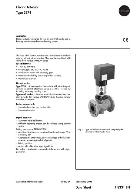
Fig. 1 ⋅ <strong>Type</strong> <strong>3374</strong> <strong>Electric</strong> <strong>Actuator</strong> with inte<strong>gr</strong>ated yoke<br />
attached to V2001 Globe Valve<br />
Edition May 2003<br />
<strong>Data</strong> <strong>Sheet</strong> T <strong>8331</strong> <strong>EN</strong>
Principle of operation<br />
The electric actuators consist of a reversible synchronous motor<br />
and a maintenance-free planetary gear with ball screw. The<br />
motor is switched off by torque-dependent switches when the<br />
end positions are reached or in case of overload.<br />
The <strong>Type</strong> <strong>3374</strong> <strong>Actuator</strong>s with inte<strong>gr</strong>ated yoke (Fig. 3a) are<br />
primarily combined with the following valves:<br />
• V2001 Series<br />
• <strong>Type</strong> 3260 in DN 65 to DN 150<br />
• <strong>Type</strong> 3214 in DN 65 to DN 100.<br />
The <strong>Type</strong> <strong>3374</strong> <strong>Actuator</strong>s with central attachment are primarily<br />
combined with valves with yokes of their own:<br />
• 240 Series (Fig. 3b)<br />
• <strong>Type</strong> 3214 in DN 125 to 250 (Fig. 3c)<br />
Fail-safe action<br />
The <strong>Type</strong> <strong>3374</strong> <strong>Actuator</strong>s are optionally available with fail-safe<br />
action:<br />
<strong>Actuator</strong> stem "extends": when the power supply fails, the<br />
actuator stem extends.<br />
<strong>Actuator</strong> stem "retracts": when the power supply fails, the<br />
actuator stem retracts.<br />
Ordering text<br />
<strong>Electric</strong> <strong>Actuator</strong> <strong>Type</strong> <strong>3374</strong>- ...<br />
Rated travel 15 or 30 mm<br />
Version with fail-safe <strong>Actuator</strong> stem extends or retracts<br />
action only with 15 mm travel<br />
<strong>Electric</strong>al connection 230 or 24 V, 50 Hz<br />
Additional electrical equipment (see Table 1)<br />
Two limit switches<br />
Two potentiometers 0 to 1000 Ω<br />
Digital positioner<br />
Specifications subject to change without notice.<br />
2<br />
3a 3b<br />
3c<br />
End position switch with tag<br />
Nennhub<br />
15<br />
Fig. 2 ⋅ Partial view with opened cover<br />
Potentiometer gears<br />
Nennhub<br />
15<br />
Microswitch Switching cam for microswitch<br />
With inte<strong>gr</strong>ated yoke for<br />
3a ⋅ V2001 Series, <strong>Type</strong> 3260 (DN 65 to 150)<br />
<strong>Type</strong> 3214 (DN 65 to 100)<br />
With central attachment for<br />
3b ⋅ 240 Series<br />
3c ⋅ <strong>Type</strong> 3214 (DN 125 to 250)<br />
240 Series (<strong>Type</strong> 3241 and <strong>Type</strong> 3244)<br />
Fig. 3 ⋅ Attachment to various valves<br />
T <strong>8331</strong> <strong>EN</strong>
Table 1 ⋅ Technichal data<br />
<strong>Type</strong> <strong>3374</strong> -10 -11 -15 -21 -26 -31 -36<br />
Fail-safe action Without With<br />
Operating direction − <strong>Actuator</strong> stem extends <strong>Actuator</strong> stem retracts<br />
Valve attach- Ring nut − − • − • − •<br />
ment with<br />
Yoke • • − • − • −<br />
Rated travel mm 30 15 30 15 15<br />
Actuating time for rated travel * s 240/120* 120/60* 240/120* 120/60* 120/60*<br />
Actuating time in case of fail-safe<br />
action<br />
− 12 s<br />
Positioning Act. stem extends 2500 2000<br />
force in N Act. stem retracts 2500 500<br />
<strong>Electric</strong>al connection 207 to 253 V, 50 Hz or 21.6 to 27.6 V, 50 Hz ⋅ Other voltages on request<br />
Power consumption Max. 18 VA<br />
Switchoff Torque-dependent<br />
Permissible ambient temperature 5 ... 60 °C<br />
Storage temperature −20 ... 70 °C<br />
De<strong>gr</strong>ee of protection IP 54 according to DIN IEC 529 ⋅ Suspended mounting not permissible!<br />
IP 65 with cable glands (M 20x1.5 with metal nut SW 23/24)<br />
Overvoltage category II<br />
Design and inspection <strong>EN</strong> 61 010 Edition 3.94<br />
Class of protection<br />
II<br />
Noise immunity<br />
<strong>EN</strong> 50 082 Part 2<br />
Noise emission<br />
<strong>EN</strong> 50 082 Part 1<br />
Manual override<br />
4 mm hex wrench ⋅ No adjustment possible after fail-safe action is triggered<br />
Weight approx. kg 3.2 3.2 3.3 3.9 4.0 3.5 3.6<br />
Additional electrical equipment<br />
Limit switches Two travel-dependent adjustable limit switches ⋅ 250 VAC, 3 A<br />
Potentiometers<br />
Digital positioner<br />
Two potentiometers: 0 ... 1000 Ω (900 Ω at rated travel), max. 1 mA ⋅ Not with version inc. positioner<br />
Input and output 4(0) ... 20 mA ⋅ 2(0) ... 10 V<br />
Operating modes Can be selected using selector switch<br />
Additional settings can be determined using TROVIS-VIEW and can be transferred using a PC or<br />
memory pen<br />
Characteristic Linear, equal percentage or freely determinable <strong>gr</strong>aph ⋅ Determinable using TROVIS-VIEW<br />
Travel adjustment During automatic travel calibration<br />
Interface <strong>Data</strong> transmission with settings, operating status, error messages per SAMSON interface protocol<br />
* Half of the actuating time on request<br />
Table 2 ⋅ Materials (WN = material number according to DIN)<br />
Housing and cover PPO glass-fiber reinforced<br />
Central attachment and yoke Flange: Aluminum, connecting thread M 30 x 1.5<br />
Formed sheet: WN 1.4301H injected into housing, bore hole 30 mm<br />
<strong>Actuator</strong> stem WN 1.4305<br />
3<br />
T <strong>8331</strong> <strong>EN</strong>
<strong>Electric</strong>al connection ⋅ Version for three-step signal<br />
<strong>Electric</strong>al connection ⋅ Version with digital positioner<br />
Dimensions<br />
120<br />
41 44 42 51 54 52<br />
V mA<br />
+ _ +<br />
mA V V<br />
+ _ +<br />
+ _<br />
31 32 33 13 12 11<br />
SAMSON AG ⋅ MESS- UND REGELTECHNIK<br />
Weismüllerstraße 3 ⋅ 60314 Frankfurt am Main ⋅ Germany<br />
Phone +49 69 4 00 9-0 ⋅ Fax +49 69 4 00 9-15 07<br />
Internet: http://www.samson.de<br />
L<br />
Ce Ce<br />
– + N N L<br />
aL eL N N L<br />
Limit switches (optional)<br />
294<br />
50 15 (30)<br />
60<br />
81 82 83 84 L N<br />
193<br />
+ _ V<br />
L N<br />
Position transmitter Input Binary Binary output Power supply<br />
input max. 25 mA<br />
eL<br />
aL<br />
Magnet for version<br />
with fail-safe action<br />
<strong>Actuator</strong> stem retracts<br />
<strong>Actuator</strong> stem extends<br />
Limit switches (optional) Potentiometers (optional)<br />
41 44 42 51 54 52 81 82 83 91 92 93<br />
90 (75) 204<br />
Magnet for version<br />
with fail-safe action only<br />
<strong>Type</strong> <strong>3374</strong>-10/-21/-31 -15/-26/-36<br />
30 (15)<br />
T <strong>8331</strong> <strong>EN</strong>


