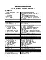
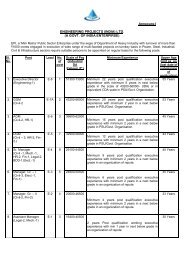
4 General Technical Specification of Bhilai Steel Plant, SAIL ...
4 General Technical Specification of Bhilai Steel Plant, SAIL ...
4 General Technical Specification of Bhilai Steel Plant, SAIL ...

Create successful ePaper yourself
Turn your PDF publications into a flip-book with our unique Google optimized e-Paper software.
© 2007 MECON Limited<br />
All rights reserved<br />
<strong>General</strong> <strong>Technical</strong> <strong>Specification</strong><br />
v) Separate seal pots shall be provided for different gasses.<br />
vi) Removal <strong>of</strong> condensate from branch line from inter shop gas pipe and inshop<br />
gas pipe should be carried out in separate condensate seal pots.<br />
vii) Minimum height <strong>of</strong> the water seal in the condensate seal pot shall exceed the<br />
maximum working pressure <strong>of</strong> gas by 500 mm, but this height in no case shall<br />
be lower than 2000 mm.<br />
If necessary, the height <strong>of</strong> water seal can be increased by adding more than one<br />
seal pot in series. However, number <strong>of</strong> such seal pots shall not exceed three.<br />
Further base plate <strong>of</strong> seal pot shall have minimum thickness <strong>of</strong> 16 mm.<br />
While installing common seal pot for a number <strong>of</strong> gas pipe, height <strong>of</strong> water seal<br />
should exceed by 500 mm the maximum working pressure in any <strong>of</strong> the<br />
connected gas pipe.<br />
viii) Design <strong>of</strong> condensate seal pots should ensure protection against leakage <strong>of</strong><br />
harmful gases into building by providing vent <strong>of</strong> adequate height on the seal pot.<br />
ix) Condensate seal pot shall be provided with purging facilities.<br />
x) Installation <strong>of</strong> condensate seal pot for in shop gas network is allowed inside the<br />
buildings.<br />
Condensate Drain Arrangement for Medium pressure High pressures gas<br />
i) Condensate disposal for gases having higher line pressure have to be done by<br />
using adequate pressure seal pots.<br />
ii) In a high pressure seal pot the metallic float is utilized for disposal <strong>of</strong> condensate<br />
and prevent leakage <strong>of</strong> gas from the pot.<br />
iii) The seal pot should be air tight and wall thickness should be decided on the line<br />
test pressure.<br />
iv) Condensate coming out <strong>of</strong> seal pot should be discharged into phenolic sewerage<br />
line or in a reservoir provided locally.<br />
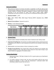
02.08. STEAM TRAPS / MOISTURE TRAPS-<br />
At low points in steam & compressed air pipeline steam traps / moisture traps with<br />
strainer assembly will be provided to drain out the condensate. Selection <strong>of</strong> steam trap<br />
shall be as per IPSS: 1-06-039 – 02. Installation <strong>of</strong> steam traps shall be as per IPSS: 1-<br />
06-037<br />
02.09. PURGING SYSTEM<br />
System for feeding purge gas and venting <strong>of</strong> gas/ air from the piping system shall be<br />
provided for all fuel gas piping.<br />
Purging<br />
i) Gas pipelines <strong>of</strong> blast furnace gas, coke oven gas, converter gas and mixed gas<br />
shall be equipped with nitrogen or steam pipe connection with isolation valve.<br />
The connection <strong>of</strong> nitrogen or steam pipeline to the gas pipeline shall be done by<br />
means <strong>of</strong> flexible hose which shall be connected only during the period <strong>of</strong><br />
purging.<br />
Gases & Liquid Fluids<br />
Page 10 <strong>of</strong> 51<br />
GS-02