4 General Technical Specification of Bhilai Steel Plant, SAIL ...
4 General Technical Specification of Bhilai Steel Plant, SAIL ...
4 General Technical Specification of Bhilai Steel Plant, SAIL ...

You also want an ePaper? Increase the reach of your titles
YUMPU automatically turns print PDFs into web optimized ePapers that Google loves.
TENDER DOCUMENT<br />
NIT No.: DLI/C&E/WI-665/284<br />
FOR<br />
Tender for ‘Design, Engineering, Supply , installation,<br />
testing & commissioning <strong>of</strong> ‘DUST SUPPRESSION<br />
PACKAGE AND ASSOCIATED WORKS’ for the<br />
project <strong>of</strong> “Augmentation <strong>of</strong> Raw Material Handling<br />
Receipt and Handling facilities with new OHP Part– B<br />
(Package- 061) <strong>of</strong> <strong>Bhilai</strong> <strong>Steel</strong> <strong>Plant</strong>, (<strong>SAIL</strong>)”.<br />
VOLUME – 4<br />
<strong>General</strong> <strong>Technical</strong> <strong>Specification</strong><br />
<strong>of</strong><br />
<strong>Bhilai</strong> <strong>Steel</strong> <strong>Plant</strong>, <strong>SAIL</strong><br />
ENGINEERING PROJECTS (INDIA) LIMITED<br />
(A GOVT. OF INDIA ENTERPRISE)<br />
Core-3, Scope Complex, 7, Institutional Area,<br />
Lodhi Road, New Delhi-110003<br />
TEL NO: 011-24361666 FAX NO. 011- 24363426
STEEL AUTHORITY OF INDIA LIMITED<br />
BHILAI STEEL PLANT<br />
GENERAL SPECIFICATION<br />
FOR<br />
PREFFERED MAKES<br />
(GS – 13)<br />
MECON LIMITED<br />
RANCHI – 834002<br />
No. MEC/S/1901/11/38/0/00/00/F1889/R2 JULY, 2007
SL.<br />
NO.<br />
© 2007 MECON Limited<br />
All rights reserved<br />
<strong>General</strong> <strong>Technical</strong> <strong>Specification</strong><br />
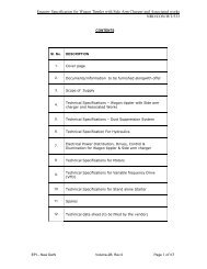
CONTENTS<br />
DESCRIPTION<br />
Preferred Makes<br />
Page 1 <strong>of</strong> 1<br />
PAGE<br />
NO.<br />
01 PREAMBLE 1<br />
02 FLUID SYSTEM 2<br />
03 VENTILATION, AIR CONDITIONING AND AIR<br />
POLLUTION CONTROL EQUIPMENT<br />
04 HANDLING & HOISTING EQUIPMENT 11<br />
05 REPAIR & MAINTENANCE FACILITIES 16<br />
06 ELECTRICAL 17<br />
07 INSTRUMENTATION 25<br />
08 FIRE PROTECTION SYSTEM 30<br />
09 BOF GCP EQUIPMENT 30<br />
10 INFORMATION SYSTEM 32<br />
11 FLUID SYSTEMS & PIPING ENGG<br />
(LUBRICATION & HYDRAULICS)<br />
9<br />
34<br />
GS-13
01. PREAMBLE<br />
© 2007 MECON Limited<br />
All rights reserved<br />
<strong>General</strong> <strong>Technical</strong> <strong>Specification</strong><br />
This document “PREFERRED MAKES OF EQUIPMENT AND SUPPLIES” is a part <strong>of</strong><br />
the tender specification for various packages <strong>of</strong> BHILAI STEEL PLANT.<br />
The makes <strong>of</strong> various equipment and supplies in respect <strong>of</strong> imported/indigenous<br />
equipment/components/materials are listed out in this document. It is essential that the<br />
equipment/component/materials to be supplied from imported/indigenous sources by the<br />
Tenderer will be <strong>of</strong> any one <strong>of</strong> the makes listed against that particular equipment/<br />
component/material in this documents..<br />
In case the Tenderer/ Contractor intends to substitute any particular make <strong>of</strong> equipment /<br />
components/ materials by a make other than that listed in this document, the Tenderer<br />
shall clearly bring out the same in his tender along with justification and indicate the<br />
alternative makes <strong>of</strong>fered by him. It will be prerogative <strong>of</strong> the Purchaser to accept or<br />
reject the alternative makes so <strong>of</strong>fered.<br />
Preferred Makes<br />
Page 1 <strong>of</strong> 37<br />
GS-13
01 FLUID SYSTEM<br />
01.01 Water Supply Facilities<br />
Sl.<br />
No.<br />
© 2007 MECON Limited<br />
All rights reserved<br />
<strong>General</strong> <strong>Technical</strong> <strong>Specification</strong><br />
Item Description Manufacturers<br />
1 Horizontal<br />
Centrifugal Pumps<br />
2 Vertical Turbine<br />
Pumps<br />
3 Vertical Wet Pit<br />
Type Pumps<br />
: Kirloskar Brothers, KSB, Beacon Weir, Khimline, Jyoti,<br />
Sintech, Ghaziabad.<br />
: Kirloskar Brothers, Voltas, WPIL, Jyoti,<br />
: SU Motors, Kishore Pumps, Kirloskar Brothers, KSB.<br />
4 Submersible Pumps : KSB, SU Motors, Kirloskar Brothers, Kishore Pumps,<br />
Darling, Beacon Weir.<br />
5 Slurry Pump : Akay, Sam Engg., MBE, KBL, KSB Pumps, WARMAN.<br />
6 Dosing Pump : Shapo Tools, Asia LMI (Madras), Positive Metering Pumps,<br />
Toshniwal, Milton Roy India.<br />
7 Cooling Towers : PCTPL, Shri Ram Tower Tech, Gammon, Himgiri, Southern<br />
Cooling Tower, BDT, GEA<br />
8 Pressure Filters : Thermax, Ion-Exchange, Resin India, Driplex, Doshion, VA<br />
Tech Wabag, UEM, Aquatech<br />
9 Sluice Gates : Jash Engineering, IVPL<br />
10 Travelling Water<br />
Screen<br />
: Macmet, Triveni, Otokiln, Mecgale (Nagpur), <strong>General</strong><br />
Mechanical<br />
11 Sludge Scrapper : Triveni, Neo – Parisrutan, Mata India, Geomiller<br />
12 Fire Hydrants : New Age Industries, <strong>Steel</strong>age Industires, ASCO, Strumech,<br />
Vijay Fire, Zenith<br />
13 Basket Strainers : Filteration Engrs, J.N Marshall, Masturlal Fabrication , ARF<br />
Engg, Purolator Filters, ABB, Filters Mfd India<br />
14 Duplex Strainers : Filteration Engrs., Otokiln, Superflo<br />
15 Rubber Dismantling<br />
Joints<br />
16 Diesel Engine<br />
17 S<strong>of</strong>tening & DM<br />
<strong>Plant</strong><br />
18 R O <strong>Plant</strong>s<br />
19 Effluent Treatment<br />
<strong>Plant</strong><br />
20 Drinking water<br />
Treatment <strong>Plant</strong><br />
: BDX, CORI Engineers, D.Wren,<br />
:<br />
:<br />
:<br />
:<br />
:<br />
Cummins/Ashok Layland/Ruston<br />
Doshi / Resin India / Thermax / Thermax Cullinyan / VA<br />
Tech / Ion Exchange /Triveni / GEA Energy Systems/<br />
Driplex Water Engg, Triveni,<br />
UEM India, VA Tech, GEA Energy Systems, Ion Exchange,<br />
Driplex Water Engg, Triveni,<br />
UEM India, VA Tech, GEA Energy Systems, Triveni,<br />
UEM India, VA Tech, GEA Energy Systems, Driplex Water<br />
Engg , Triveni,<br />
21 Basalt Liners : DEMECH, Vidyut Green Bank, Enviro Abrasian, Garden<br />
Preferred Makes<br />
Page 2 <strong>of</strong> 37<br />
GS-13
Sl.<br />
No.<br />
© 2007 MECON Limited<br />
All rights reserved<br />
<strong>General</strong> <strong>Technical</strong> <strong>Specification</strong><br />
Item Description Manufacturers<br />
22 Oil Skimmer : JVM Engg.<br />
23 Plate Heat<br />
Exchangers<br />
Reach Ship Builders & Engg.<br />
: Alfalaval, GEA Ec<strong>of</strong>lex, IDMC<br />
24 Surge Tanks : Anup Engg., Zenith Erectors, Haldia., Perfect Engg., Sakthi<br />
Hitech<br />
25 C.I. Valves (gate,<br />
globe, NRV)<br />
26 CS Valves (gate,<br />
NRV)<br />
: Kirloskar Brothers, Steam & Mining, IVPL, AV Valves, Shiv<br />
Durga, BDK, Fouress.<br />
: Audco, Fouress, BHEL, Sakhi, KSB, Steam & Mining, BDK,<br />
Kirloskar, Virgo<br />
27 Plug Valves : Audco- L&T, Vass Ind., Xomox, Virgo, BDK, Steam &<br />
Mining.<br />
28 Ball Valves : Audco, KSB, AL Saunders, Xomox, Virgo, BDK, Virgo ,<br />
29 GM Valves : Leader, Steam & Mining, NECO, Upadhyay Valves, Kalpana<br />
Valves<br />
30 Butterfly Valves<br />
:<br />
L&T, Fouress, Kirloskar Brothers, IVPL, VIRGO, AL<br />
(Manually &<br />
electrically<br />
operated)<br />
Saunders, Steam & Mining, Keystone, BDK, XOMOX.<br />
31 Diaphragm Valves<br />
:<br />
AL Saunders, Fluid System, BDK , Steam & Mining.<br />
32 Float Valve<br />
:<br />
Leader, IVPL, IM Engineers, Steam & Mining.<br />
33 Control Valve<br />
:<br />
BHEL, L&T, Fouress, IL, MIL Controls, NECO Scharbet,<br />
Darling<br />
34 Solenoid Valve<br />
:<br />
Rotex, Sicmag, Scharder, NECO INDFOS, Eastern<br />
Pneumatic, Bluestar, AVCON, ASCO, Mercury<br />
35 Air Release Valve<br />
:<br />
Shiva Durga, IVPL, IM Engineers, Steam & Mining,<br />
Schroder Duncum, Fluid Line Valves.<br />
36 Pressure Reducing<br />
:<br />
JNM, Fouress, Bestobell, IL, Mazda, Nirmal Ind., Forbes<br />
Valve<br />
Marshal<br />
37 Strainer/Filter<br />
:<br />
Otokiln, Superflo, Triveni Plenty, Filter Mfg. Ind., Purolator,<br />
Filteration Engineers<br />
38 Electric Actuators<br />
:<br />
Beacon Rotork, Auma, Marsh Engineers, Keystone,<br />
Limitorque, Antrieb, IL, Palghat<br />
39 Rotory Pneumatic<br />
:<br />
AL Saunders, Xomox, EL-O-Matic, Virgo, L&T, Flocon,<br />
Actuators<br />
Precision Processing Equipt. Co.<br />
40 Hoses<br />
:<br />
Aer<strong>of</strong>lox/Markwel/Senior Flexonics, Inalsa, Teksons<br />
41 Pipes a) MS/GI<br />
:<br />
<strong>SAIL</strong>/TATA/Jindal/Zenith/Man/SAW/Surindra/Welspun/Prak<br />
esh<br />
b) DI<br />
:<br />
Electro <strong>Steel</strong> Casting<br />
42 RCC Pipes &<br />
Fittings<br />
: SUR Industrial Pipes, Hind Ceramics, Indian Hume Pipes,<br />
Daya Cuncrching.<br />
43 HDPE Pipes & : EMCO, KWH Heliplastic Polyolefins, Oriplast<br />
Preferred Makes<br />
Page 3 <strong>of</strong> 37<br />
GS-13
Sl.<br />
No.<br />
© 2007 MECON Limited<br />
All rights reserved<br />
<strong>General</strong> <strong>Technical</strong> <strong>Specification</strong><br />
Item Description Manufacturers<br />
Fittings<br />
44 PVC Pipes &<br />
Fittings<br />
45 SS Pipes / SS<br />
Fittings<br />
46 Seamless, Stainless<br />
<strong>Steel</strong> Pipes/Tubes<br />
47 Fittings for the<br />
above Pipes/Tubes<br />
48 Wrapping & Coating<br />
for pipes<br />
49 Chemical Dosing<br />
System<br />
: Oriplast, Finolex, Bharat Pipe & Fittings, Supreme<br />
Industries.<br />
:<br />
:<br />
:<br />
Heavy Metal Tubes, Nobel Tubes, Rajendra Mech. Ind.,<br />
Vitrag, <strong>SAIL</strong>, Poonam Enterprises, N.L.Hazra, M.S.Fittings<br />
Choksy Tubes, MJ Patel, Nagardas Kanji, Poonam<br />
Enterprises, Sandulk Asia, Noble Tubes, Allied <strong>Steel</strong>, <strong>SAIL</strong>,<br />
Maharastra Seamless (P) Ltd,<br />
EBY Ind., High-Tech, Hydro technic, Hydro-Air Engg.,<br />
Project Toolings, Shivananda, M.J.Patel, Nobles Tubes,<br />
Allied <strong>Steel</strong>, Poonam Enterprises, N.L.Hazra, M.S.Fittings<br />
: Rustech Products, HOTACO, IWL, M P Tar Products<br />
Hindustan Dorr Oliver, Tellabs Chemicals,<br />
Chembonddrewtreat ltd., NALCO<br />
01.02 Valves For Fuel Gas, Steam, Nitrogen, LPG & Compressed Air Facilities<br />
Item Description Manufacturers<br />
C.I. Valves for Fuel Gas &<br />
Compressed Air (gate,<br />
globe, NRV)<br />
CS, FS, SS Valves for<br />
Steam, Feed Water, &<br />
LPG (Gate, Globe, NRV)<br />
CI, CS, SS & FS Plug<br />
Valves<br />
Ball Valves :<br />
GM Valves :<br />
: Kirloskar Brothers, GM Dalui, Steam &<br />
Mining, H.Sarker, IVPL, AV Valves, Leader,<br />
Associated tooling, BDK, Kalpana Valves<br />
: L&T (Audco Div), Fouress, BHEL, KSB, GM<br />
Dalui, Leader, BDK, NECO, Associated<br />
Tooling, Hawa Egr., Vass Ind, Advance<br />
Valves, Kalpana Valves<br />
: Vass Ind., Xomox, Virgo, BDK, Leader,<br />
Steam and Mining, GM Dalui, H.Sarkar,<br />
Audco<br />
Audco, Vass Ind, KSB, BDK, Micr<strong>of</strong>inish,<br />
Niton,AL Saunders, Xomox, Virgo, United<br />
Engineers, Steam & Mining, Hi-Tech<br />
B.Valves<br />
Bombay Metals, GM Dalui, Leader, NECO,<br />
Kalpana Valves<br />
Preferred Makes<br />
Page 4 <strong>of</strong> 37<br />
GS-13
© 2007 MECON Limited<br />
All rights reserved<br />
Butterfly Valves :<br />
Diaphragm Valves :<br />
Pressure Control<br />
Valve/Pressure Reducing<br />
Valve<br />
Large Diameter Goggle<br />
Valve<br />
Fabricated Gate Valves :<br />
Safety Relief Valve<br />
(Pressure relief Valves)<br />
<strong>General</strong> <strong>Technical</strong> <strong>Specification</strong><br />
:<br />
:<br />
:<br />
Audco, Fouress, Kirloskar Brothers, IVPL,<br />
Inter Valve, Virgo, AL Saunders, Keystone,<br />
BDK, Leader, AVC Engg., Crowley & Ray,<br />
Xomox, Tyco, Hi-Tech.<br />
AL Saunders, Fluid System, Leader, BDK,<br />
Xomox, Steam & Mining<br />
JNM, Fouress, Bestobell, IL, Mazda, Nirmal<br />
Ind., Vanaz, Kosan Metal, Vass Ind., RK<br />
Control, Fluid Line, Forbes Marshal, Leader.<br />
Audco, Fouress, Cimmco, L&T<br />
Fouress, Cimmco, BECO, Beekay, L&T,<br />
Kalpana Valves<br />
BHEL, Keystone, Bliss Anand, L&T (Audco<br />
Div.), Sempell, Fainger, Leser Valves (P)<br />
Ltd., IL, Anderson, Kosan.<br />
02.03 Miscellaneous Gas Facility & Compressed Air Equipment<br />
Item Description Manufacturers<br />
Oxygen Acetylene & LPG<br />
Manifolds<br />
SS Bellows Expansion<br />
Joints<br />
Centrifugal Gas Booster :<br />
Twin Lobe Type Booster :<br />
:<br />
:<br />
Kamrup Industrial Gases, INOX, Titan<br />
Engg., BOC, Ramba Hydrogen, Asiatic<br />
Oxygen<br />
Flexican, Flexatherm, SURR Ind., Pressel<br />
(Cuttack), BD Engr., Eludyne Engr., SPB,<br />
SEPL, PEBI, Lonestar, GBM Mfg., TI<br />
Flexible Tube.<br />
Andrew Yule, TLT, James Howden (U.K),<br />
Donkin (U.K), Hibhen<br />
Skoda, CKD Kompressors, MD Pneumatics,<br />
Demag Delavl, Bryan Donkin Sulzer, Oil &<br />
Gas <strong>Plant</strong> Engg., (Tuthill), Kay International<br />
Preferred Makes<br />
Page 5 <strong>of</strong> 37<br />
GS-13
© 2007 MECON Limited<br />
All rights reserved<br />
<strong>General</strong> <strong>Technical</strong> <strong>Specification</strong><br />
Gas/Air Compressors :<br />
Hoses :<br />
Valves for Oxygen Services:<br />
Item Description Manufacturers<br />
1. Non-Ferrous:<br />
For Isolation :<br />
Ingersoll Rand, Atlas Copco, KG Khosla,<br />
Kirloskar Pneumatic, Chicago Pneumatic,<br />
Mannesman Demag, Eliat, Cooper, Sulzor,<br />
Corken (USA)<br />
Flexican, Gaytri Industrial Corpn., Inalsa,<br />
Teksons, Sudeep Industries, Markwell<br />
Preferred Makes<br />
Page 6 <strong>of</strong> 37<br />
Bestobell (UK), ETH IRELAND (France),<br />
RT Orseal (UK), Truflo (Belgium),<br />
Worcestor Controls (UK),<br />
Quick Sheet-<strong>of</strong>f Valve : Bestobell (UK), ETH IRELAND (France),<br />
RT Orseal (UK), Truflo (Belgium),<br />
Worcestor Controls (UK), Moorco, SEBIM<br />
Pressure Control Valve (PCV) &<br />
Flow Control Valve (FCV)<br />
: SEVERN (UK), NELES SECK GLOKON<br />
(UK), IL (Palghat)<br />
Solenoid Valve : AVCON, SEITZ, ROTEX, ASCO<br />
Safety Relief Valve (SRV) : KUNKLE (USA), KEYSTONE (USA),<br />
BROADY (UK), MOORCO, SEBIM, IL<br />
(Palghat)<br />
Pressure Regulators (Self<br />
regulating with pressure<br />
gauge)for Oxygen<br />
2. Stainless <strong>Steel</strong> (SS)<br />
(manual)<br />
POWER & ENERGY<br />
: ESAB, BOC, Speciality Gases, Kamrup<br />
Industrial Gases, Venaz Engineers, Nirmal<br />
Ind.<br />
: Precision Engg., BDK, Niton, Akay, Leader,<br />
Audco, Sakhi & Co., KSB<br />
GS-13
© 2007 MECON Limited<br />
All rights reserved<br />
<strong>General</strong> <strong>Technical</strong> <strong>Specification</strong><br />
Item Description Manufacturers<br />
Air Drying Uuit :<br />
Condensate Pumps :<br />
Ejector :<br />
Trap & Strainer for<br />
Compressed Air & Steam<br />
Actuators<br />
Electrical<br />
Pneumatic<br />
Heat Exchanger<br />
(Shell & Tube Type)<br />
Control Valves :<br />
Pressure Vessel & Tanks :<br />
Thermal Insulation :<br />
Suction Filters :<br />
:<br />
:<br />
:<br />
:<br />
Chemech, Cleanair, Delair, Indcon, Mellcon,<br />
Mirch Mirex, Gasoenergy System Pune.<br />
KSB, BHEL, Kirloskar Brothers, Mather &<br />
Platt, Khimline, Sigma<br />
BHEL, Weigand, Newfield, Mazda<br />
Uniklinger, ESCO, JNM, Dryton Greaves,<br />
Forbes Marshall, Hawa Engrs., Mazda<br />
AUMA India, Beacon Rotork Controls,<br />
Continental Pr<strong>of</strong>iles, Emtork Actuators,<br />
Limitorque<br />
Marsh Engg., Keystone, IL, Massoneilan, EL-<br />
O-MATIC, Virgo, AL Saunder, L&T, Flocan<br />
BHPV, Kaveri, Texmaco, Thermax, Babcock<br />
& Wicox, Parkair Engg., Rhine, Universal<br />
Heat Exchanger, Godrej, L&T, GEI Godavari,<br />
Patel Air Temp., Hindustan Radiaton<br />
Blue Star, Fouress Engg., IL, JNM, Mazda,<br />
Forbes Marshall<br />
Beekay Engg., BHPV, ISGEC, Kaveri Engg.,<br />
TSL, Lloyds <strong>Steel</strong>, Mukand, Parkair Engg.,<br />
Grasim Industries, Anup Thermal System,<br />
Texmaco, SV Tank, Grasim Industries,<br />
Hyderfuel Industries.<br />
Hyderapad Industries, Lloyds Insulation,<br />
Rockwool, Thermax Heat Tracers, U.P.<br />
Twiga Fibreglass.<br />
FMI, KAAF, L&T, Flakt, Autokiln Filter, GEC<br />
Alsthom, Filtration Engr., ARF Engg., ABB,<br />
Dyna Filter, Purolator Filters, GM Dalui<br />
Preferred Makes<br />
Page 7 <strong>of</strong> 37<br />
GS-13
© 2007 MECON Limited<br />
All rights reserved<br />
<strong>General</strong> <strong>Technical</strong> <strong>Specification</strong><br />
02.04 Pipes & Fittings for Water Supply, Gas Facilities, Steam and Compressed Air<br />
Facilities.<br />
Item Description Manufacturers<br />
SW/SAW, ERW/EFW MS<br />
Pipes<br />
SS Pipes / SS Fittings :<br />
Seamless, Stainless <strong>Steel</strong><br />
Pipes/Tubes<br />
Fittings for the above<br />
Pipes/Tubes<br />
RCC Pipes & Fittings :<br />
:<br />
:<br />
:<br />
<strong>SAIL</strong>, BHEL, TISCO, Jindal, Ajanta, Zenith,<br />
Saw Pipes, Welspun, Man Industries,<br />
Surindra Engg., Maharastra Seamless,<br />
Indian Seamless, BST, Advance <strong>Steel</strong>, Good<br />
Luck, Indus Tubes, Mukat, Lloyds, Poonam<br />
Enterprises, Soor Neogi Koumar.<br />
Heavy Metal Tubes, Nobel Tubes, Rajendra<br />
Mech. Ind., Sterling Supply Agency, Vitrag,<br />
<strong>SAIL</strong>, Poonam Enterprises, N.L.Hazra,<br />
M.S.Fittings<br />
Amardeep <strong>Steel</strong>, Choksy Tubes, MJ Patel,<br />
Nagardas Kanji, Poonam Enterprises,<br />
Sandulk Asia, MEC Tubes, Nagardas &<br />
Kusai, Noble Tubes, Allied <strong>Steel</strong>, Kamlesh<br />
Tube, Menilal & Bro, Uday Tubes, <strong>SAIL</strong>,<br />
Maharastra Seamless (P) Ltd, Imperial<br />
<strong>Steel</strong>, Soor Neogi Koumar.<br />
EBY Ind., High-Tech, Hydro technic, Hydro-<br />
Air Engg., Project Toolings, Shivananda,<br />
M.J.Patel, Nagardas & Kusai, MEC Tubes,<br />
Nobles Tubes, Amardeep <strong>Steel</strong>, Allied <strong>Steel</strong>,<br />
Kamlesh Tube, Menilal & Bros, Poonam<br />
Enterprises, N.L.Hazra, M.S.Fittings<br />
SUR Industrial Pipes, Hind Ceramics, Indian<br />
Hume Pipes, Daya Cuncrching.<br />
HDPE Pipes & Fittings : EMCO, KWH Heliplastic Polyolefins, Oriplast<br />
PVC Pipes & Fittings :<br />
Oriplast, Finolex, Bharat Pipe & Fittings,<br />
Supreme Industries.<br />
Preferred Makes<br />
Page 8 <strong>of</strong> 37<br />
GS-13
© 2007 MECON Limited<br />
All rights reserved<br />
<strong>General</strong> <strong>Technical</strong> <strong>Specification</strong><br />
03. VENTILATION, AIR CONDITIONING & AIR POLLUTION CONTROL EQUIPMENT<br />
Item Description Manufacturers<br />
Centrifugal fans for<br />
Ventilation<br />
Centrigugal fans for<br />
Dedusting<br />
Tube axial fans / Propeller<br />
Fans<br />
: C.Doctor, EFE, AEROVENT, Flow Link,<br />
Andrew Yule, RIECO, ISEL, BATLIBOI,<br />
Flaktwood, REITZ, ACCEL, Dustven,<br />
INDFAN,<br />
:<br />
BHEL, TLT, C.Doctor, Andrew Yule, RIECO,<br />
Batliboi, F.Harley, Flaktwood, REITZ,<br />
DUSTVEN, ISEL, INDFAN<br />
: C.Doctor, EFE, Flow Link, ALMONARD,<br />
ACCEL, KHAITAN, AEROVENT, ISEL,<br />
INDFAN<br />
Panel filter for air : FMI, Clean Filter Industries, EFE, ACCEL,<br />
FILTRONIC, FLOWLINK, CADILLAC, C.<br />
DOCTOR<br />
Air washer :<br />
Man coolers :<br />
Ro<strong>of</strong> exhauster :<br />
Window air conditioners :<br />
Packaged air conditioners :<br />
C.Doctor, EFE, FLOW LINK, FHARLEY,<br />
ALSTOM, Dustven, BATLIBOI, FMI<br />
C.Doctor, Ventura, LM ENGINEERS,<br />
KHAITAN, ALMONARD, DUSTVEN,<br />
FLOWLINK<br />
C.Doctor, EFE, ACCEL, ALMONARD,<br />
FLOWLINK, INDFAN, AEROVENT<br />
Fedders Lloyd, VOLTAS, Blue Star, ARCTIC,<br />
Carrier Aircon, LG, Samsung, HITACHI<br />
VOLTAS, Blue Star, KIRLOSKAR, ACCEL,<br />
BATLIBOI, EMERSON, FEDDERS LLOYDS,<br />
ROOS TEMPKOOL, ROOTS COOLING<br />
Preferred Makes<br />
Page 9 <strong>of</strong> 37<br />
GS-13
© 2007 MECON Limited<br />
All rights reserved<br />
<strong>General</strong> <strong>Technical</strong> <strong>Specification</strong><br />
Item Description Manufacturers<br />
Packaged chillers :<br />
Air handling units :<br />
Cooling towers :<br />
VOLTAS, Blue Star, ALSTOM, Batliboi,<br />
ACCEL, FEDDERS LLOYD, KIRLOSKAR,<br />
PNEUMATIC<br />
VOLTAS, BLUE STAR, ALSTOM, BATLIBOI,<br />
PATELS AIR TEMP, ROOTS COOLING<br />
PAHARPUR, MIHIR, ADVANCE, GAMMON<br />
INDIA, Southern Cooling Towers Ltd.,<br />
SHRIRAM TOWER TECH.<br />
Refrigerant compressors : VOLTAS, SHRIRAM, ACCEL, BLUE STAR, ,<br />
Atlas Copco, Kirloskar, HITACHI<br />
Cyclones :<br />
THERMAX, RIECO, ALSTOM, C.DOCTOR,<br />
F.HARLEY, Dustven, EFE<br />
Multicyclones : THERMAX, ALSTOM, C. DOCTOR,<br />
BATLIBOI, RIECO, F.HARLEY, EFE<br />
Bag filters<br />
(Cap – 10,000 m 3 /h to<br />
80, 000 m 3 /h)<br />
Bag filters<br />
(Cap –Above 80,000 m 3 /h)<br />
Wet scrubbers :<br />
Venturi scrubbers :<br />
Electrostatic precipitators :<br />
: THERMAX, ALSTOM, ANDREW YULE,<br />
RIECO, C.DOCTOR. F.HARLEY, Dustven,<br />
BATLIBOI, FMI<br />
:<br />
ALSTOM, RIECO, THERMAX, VAI, Dustven,<br />
BATLIBOI<br />
ALSTOM, THERMAX, BATLIBOI, RIECO,<br />
C.DOCTOR, F.HARLEY, EFE, SOIL &<br />
ENVIRO SYSTEM<br />
BATLIBOI, THERMAX, RIECO, ALSTOM,<br />
Dustven<br />
ANDREW YULE, THERMAX, BHEL,<br />
VOLTAS, ABB, VAI<br />
Insulation TWIGA, LLOYDS, BAKELITE HYLAM,<br />
MALANPUR ENTECH<br />
Valves for air conditioning : DANFOSS, HONEYWELL, BLUE STAR<br />
Vibration isolators : DUNLOP, EMERALD<br />
Centrifugal horizontal<br />
pumps<br />
Horizontal split casing<br />
pumps<br />
:<br />
:<br />
KSB, BEACON WEIR, VOLTAS,<br />
KIRLOSKAR<br />
VOLTAS, BEACON WEIR, KSB,<br />
KIRLOSKAR<br />
Preferred Makes<br />
Page 10 <strong>of</strong> 37<br />
GS-13
© 2007 MECON Limited<br />
All rights reserved<br />
<strong>General</strong> <strong>Technical</strong> <strong>Specification</strong><br />
04. HANDLING & HOISTING EQUIPMENT & COMPONENTS<br />
04.01 Equipment<br />
Item Description Manufacturers<br />
EOT Crane<br />
(Up to 10T capacity)<br />
EOT Crane<br />
(Up to 50 T capacity)<br />
EOT Crane<br />
(Above 50 T capacity)<br />
: Armsel, Avon, FAFECO, Mukand, WMI,<br />
Anupam, Shivpra, Tubr<strong>of</strong>urguson<br />
:<br />
HEC, Jessop, Mukand, Hyderabad Ind. Ltd.,<br />
WMI, FAFECO, Unique, Anupam<br />
: Jessops, HEC, Mukand, FAFECO, Unique,<br />
WMI, .<br />
Underslung Cranes (Upto<br />
5t only)<br />
: Armsel, Brady & Morris, Shivpra<br />
Electric Hoists : Armsel, Shivpra,WH Brady, Brady & Morris,<br />
Grip Engrs., Hi-tech, Century Crane<br />
Transfer Cars : HEC, L&T, Hyderabad Ind., Mukand, Eqipt<br />
Engrs, ELECON, TRF<br />
Chain Pulley Blocks &<br />
hand operated travelling<br />
cranes.<br />
: Armsel, Century Cranes, Brady & Morris, Light<br />
Lift Ind., Hi-tech, MR Engg. Lifting Equipment<br />
Shunting Winch : Beekay, HEC, Armsel, Century Cranes, Nirmal<br />
Equipments, Mining & MH Equipment, Cyclo<br />
transmission<br />
Jib Crane : Brady & Morris, Century Cranes, Hi-tech, Grip<br />
Engrs., Elite, Light Lifting, Armsel<br />
Crawler Mounted Mobile<br />
Crane<br />
: TIL, Hyderabad Industries, TATA-P&H<br />
Excavator/ Shovel : TIL, HEC, Hyderabad Industries, BEML<br />
Elevator/Lift : OTIS, OMEGA, Kone, ECE<br />
Preferred Makes<br />
Page 11 <strong>of</strong> 37<br />
GS-13
© 2007 MECON Limited<br />
All rights reserved<br />
<strong>General</strong> <strong>Technical</strong> <strong>Specification</strong><br />
04.02 Mechanical Components/ Equipment<br />
Item Description Manufacturers<br />
Hooks : Herman Mohta, Free Trading Corporation,<br />
<strong>Steel</strong> Forgings & Engg..<br />
Flexible / Geared coupling : Hicliff, Concord, Wellman, GBM, Alliance, New<br />
Allenbery Works,Elecon,<br />
Wire rope : Bharat Wire Rope, Orion Ropes, Usha Martin<br />
Bearings for Cranes : SKF, FAG<br />
Bearings for other<br />
equipment<br />
: SKF, FAG, Tata Timken, Asian Bearings,<br />
NRB,MBM<br />
Oil Seals : Vaco Oil Seals, Rubber Equipment & Engg.<br />
Sealjet India (Pune), Sealpack, Champion<br />
Seals<br />
Lubrication Fittings : Lubcon, AFMC, Prakash, Lincoln<br />
Lubricating Systems : AFMC, Prakash, Grindwell Norton, Lincoln<br />
Helios<br />
Gear box : New Allenburry, Greaves Cotton, ELECON,<br />
Shanti Gears, Flender, AR Engg, Kirloskar,I.C.<br />
Hydraulic Systems : Vickers Sperry, Yuken, Manesmann, Rexroth,<br />
Hugglands Denison-Parker<br />
Hydraulic Coupling : Fluidomat, Ghatge Patil, VOITH, Prembrill<br />
Centrifugal blowers : REITZ, Flaht Wood, James Howden (UK)<br />
Burners : Stein Heurtey, Techint, LOI, Weswan North<br />
American, Ecllpse, Hotwork<br />
Recuperators : Eastern Equipment, GEFFI (Germany)<br />
SAFMAT (France), North American Minnt. Co.<br />
Thermal Transfer Corporation (USA)<br />
Preferred Makes<br />
Page 12 <strong>of</strong> 37<br />
GS-13
© 2007 MECON Limited<br />
All rights reserved<br />
<strong>General</strong> <strong>Technical</strong> <strong>Specification</strong><br />
Item Description Manufacturers<br />
Hydraulic<br />
Power/Cylinders<br />
High Pressure<br />
Vane/Piston Pump<br />
: Rexroth, Vickers, Wipro, Usha Telehoist,<br />
Veljan, Yuken, Oscar.<br />
: Vickers, Yuker, Rexroth, Hugglands, Denison<br />
Crusher : Sayaji, HEC, McNally Bharat, TRF, ELECON<br />
DCEM Brake : Electromag, BCH, Industries Syndicate, Storm<br />
Kraft, Speed-O-Control<br />
Track type Limit Switch : Electromag, BCH, Speed-O-Control, Jayshree,<br />
EP&C, Bengal Technocrats<br />
Thruster Brake : Electromag, BCH, Speed-o-Control, Elite<br />
Belt changing Device : Nilos, Shawalmex<br />
Conveyor Belting : Northland Rubber, Phoenix-Yule, Oriental<br />
Rubber<br />
Vibrating Screen : IC, TRF, ELECON, McNally Bharat, L &T, HEC,<br />
Orien, Electromag, Hydrabad Industries<br />
Vibratory Feeder : Electromag, IC, TRF, Orien Engineers,<br />
ELECON, McNally Bharat<br />
Magnetic Separators : Electromag, WMI, Magnet Corporation, Electro<br />
magnetic Ind., Ericz, Sartorius, Hans Bockels,<br />
Krupp Forder, Technick ,L & T<br />
Pneumatic Actuators : Prepec, Technomech, Nucon Industries,<br />
OSCAR Equipt, Veljan Hydair.<br />
Electro Mechanical<br />
Actuators<br />
:<br />
PREPEC, Technomech, Pebco<br />
Preferred Makes<br />
Page 13 <strong>of</strong> 37<br />
GS-13
© 2007 MECON Limited<br />
All rights reserved<br />
<strong>General</strong> <strong>Technical</strong> <strong>Specification</strong><br />
Item Description Manufacturers<br />
Rubber liner : TEGA, Kaveri<br />
Polymer liner :<br />
Polyethelene liner :<br />
Polyurethane liner :<br />
Cast Basalt liner :<br />
Belt Scraper/ Belt<br />
Cleaner<br />
TEGA, Kaveri<br />
Kaveri, Tega<br />
Kaveri, Tega<br />
DECCAN, Enviro Abrasion<br />
: Hosch Equipment, Vinar IDC, Kaveri Macmet,<br />
Hindustan Udyog Ltd., Karam Chand Thapper,<br />
Cobit Engg, Elecon, TRF, Promac, BMH<br />
Concare<br />
Belt Switches : Jayshree, PROTO CONTROL, EPC<br />
Bin Vibrator : Electromag, Electromagnetic Industries, IC<br />
Samplers :<br />
Belt Vulcanisers :<br />
Sector Gates, Diverter<br />
Gates, Rack and Pinion<br />
Gates etc.<br />
Flexowel Conveyors :<br />
Drag Chain Conveyors :<br />
:<br />
Prisector (UK), Ramsay Engg (USA), Eastmn<br />
Crusher, Advanced system sampling (P) Ltd.<br />
Shaw Almex, Nilos India, SV Dattar<br />
Vinar, IDC, Macmet, TRF, Precision<br />
Processing, Moktali, Holtzman, Mining &<br />
Material, Chennai Radha,<br />
METSO, Flexowel<br />
Moktali Engrs., TRF, Equipt Engrs, Redler<br />
India, Enviro Abrasion, Karam Chand Thapar,<br />
Preferred Makes<br />
Page 14 <strong>of</strong> 37<br />
GS-13
© 2007 MECON Limited<br />
All rights reserved<br />
<strong>General</strong> <strong>Technical</strong> <strong>Specification</strong><br />
Item Description Manufacturers<br />
Bucket Elevator :<br />
Belt Feeder :<br />
Reclaimer :<br />
Stacker :<br />
Stacker – Cum-<br />
Reclaimer<br />
:<br />
Wagon Tippler :<br />
Wagon Loader :<br />
Belt Weigh Feeders &<br />
Weigh Hopper<br />
Belt Weigh Scale :<br />
:<br />
Moktali, Golden Electrical, Hindustan Udyog,<br />
Vinar, Cobit, Shree Conveyor, IDC, Orien,<br />
Macmet, Elecon, TRF<br />
Vinar, IDC, HEC, Orien, Macmet, Elecon, TRF,<br />
Cobit<br />
Metso, L&T, Elecon, TRF, HEC<br />
Metso, L&T, Elecon, TRF, HEC<br />
Metso, L&T, Elecon, TRF, HEC<br />
L&T, HEC, Elecon, TRF, Metso<br />
L&T, HEC, Elecon, TRF, Metso<br />
Kistler – Morse, Sartorius Mechatronics,<br />
Transweigh, Avery, Jenson Nicholson<br />
Kistler-Morse, Transweigh, Avery, Sartorius<br />
Mechatronics, Jenson Nicholson<br />
Conveyor belt pulleys : Elecon, TRF, McNally Bharat, Macmet, HEC<br />
Conveyor Idlers :<br />
Pneumatic Handling<br />
Equipment<br />
Front – end – loader :<br />
Fork-lift-truck :<br />
:<br />
Elecon, TRF, McNally Bharat, Kali, Hindustan<br />
Udyog Ltd., Macmet<br />
TTG, Scorpio<br />
TIL, Hyderabad Industries Ltd.,<br />
Godrej, Voltas, TIL<br />
Preferred Makes<br />
Page 15 <strong>of</strong> 37<br />
GS-13
© 2007 MECON Limited<br />
All rights reserved<br />
<strong>General</strong> <strong>Technical</strong> <strong>Specification</strong><br />
05. REPAIR & MAINTENANCE FACILITIES<br />
Item Description Manufacturers<br />
Centre Lathe :<br />
Universal Milling m/c :<br />
Shaper :<br />
Radial Drilling m/c :<br />
Horizontal Boring m/c :<br />
Submerged Arc Welding<br />
Set<br />
HMT, Mysore Kirloskar, HEC<br />
HMT, BFW, Batliboi<br />
PAL, P&B, Loyal<br />
HMT, Batliboi, Kerry Jost, HEC<br />
HMT, HEC, PAL<br />
: Advani, ESAB, ADOR, Mogora, COSMIC<br />
Welding Rectifier : Advani, ESAB, ADOR, Mogora, COSMIC<br />
Welding Transformer : Advani, ESAB, MEMCO<br />
Universal Tool and Cutter<br />
Grinding m/c<br />
: HMT, Praga, Batliboi<br />
Hydraulic Press : BEMCO, P&B, Centerprise<br />
Cast Iron Plate : Jash, Madras Gauge, P&B<br />
Power Hacksaw : ITL, P&B, EIFCO<br />
Column Drilling m/c : HMT, Thakoor, Kerry Jost, EIFCO, Batliboi<br />
Bench Drilling m/c : Accuax, EIFCO, P&B, Thakoor<br />
Double-ended Pedestal<br />
Grinder<br />
: Grind Tools, GECO, AMC, P&B<br />
Cylindrical Grinder : HMT, Mysore Kirloskar, ELP<br />
Tools & Tackles : P&B, Mekaster, Centerprise, Ally<br />
Measuring Tools and<br />
Gauges<br />
: P&B, Bombay Tools<br />
Garage Equipment : ELGI, USHA, WAP, P&B<br />
Oiling & Greasing : ELGI, P&B<br />
Preferred Makes<br />
Page 16 <strong>of</strong> 37<br />
GS-13
06. ELECTRICAL<br />
© 2007 MECON Limited<br />
All rights reserved<br />
<strong>General</strong> <strong>Technical</strong> <strong>Specification</strong><br />
The list <strong>of</strong> acceptable makes for various electrical and automation equipment is given below.<br />
A ) POWER DISTRIBUTION EQUIPMENT<br />
SL.<br />
NO.<br />
1. TRANSFORMERS<br />
EQUIPMENT PREFERRED MAKES<br />
a) DISTRIBUTION<br />
TRANSFORMER (OIL<br />
TYPE) (11 or 6.6/0.433<br />
KV)<br />
b) DRY TYPE<br />
TRANSFORMER<br />
ABB / AREVA / / CGL / BHEL / BHARAT BIJLEE / VOLT<br />
AMP/ KIRLOSKAR /INTRA VIDYUT /<br />
INTRA VIDYUT / VOLTAMP / KEC<br />
2. 11kV / 6.6KV ISOLATOR A BOND STRAND / S&S,MADRAS / HIVELM / SIEMENS /<br />
DREISCHER-PANICKER.<br />
3. 415V SWITCHBOARD SIEMENS / L&T / GE POWER / SCHNEIDER<br />
4. LT BUSDUCT STARDRIVE / C&S / PCE / ECC / BRIGHT ENGINEERS/<br />
VIDHYUT CONTROL<br />
5. BATTERY<br />
a) NICKEL - CADMIUM AMCO / HBL NIFE<br />
b) VALVE REGULATED<br />
LEAD ACID<br />
MAINTENANCE FREE<br />
BATTERY (VRLA)<br />
HBL NIFE / AMARARAJA / EXIDE<br />
c) BATTERY ( PLANTE) HBL NIFE / AMARARAJA / EXIDE<br />
6. BATTERY CHARGER/<br />
DCDB<br />
CHHABI / HBL NIFE/ CALDYNE / AMARA RAJA /<br />
KIRLOSKAR<br />
7. PROTECTIVE RELAYS AREVA / ABB / SIEMENS/ER<br />
8. AUXILIARY RELAYS ABB / ER / SIEMENS / AREVA<br />
9. HEAT SRINKABLE<br />
CABLE JOINTING KITS/<br />
STRAIGHT THROUGH<br />
JOINTS (H.T)<br />
10. METER (ANALOGUE<br />
TYPE)<br />
11. CURRENT<br />
TRANSFORMERS<br />
12. POTENTIAL<br />
TRANSFORMER<br />
RAYCHEM / DENSON / M-SEAL<br />
IMP / AE / MECO / SECURE METERS / CONZERV / L&T /<br />
RISHAV<br />
ABB / SILKANS / INSTRANS / PRAGATI / IMP/ AE /<br />
KAPPA / PRAYOG / SIEMENS / L&T<br />
ABB / BHEL / SILKANS / PRAGATI / IMP / KAPPA /<br />
PRAYOG /SIEMENS / ABB / INDOCOIL / PRECISION<br />
Preferred Makes<br />
Page 17 <strong>of</strong> 37<br />
GS-13
SL.<br />
NO.<br />
© 2007 MECON Limited<br />
All rights reserved<br />
<strong>General</strong> <strong>Technical</strong> <strong>Specification</strong><br />
EQUIPMENT PREFERRED MAKES<br />
13. 11KV/ 6.6KV CABLES ASIAN CABLES (RPG) / CCI / UNIVERSAL / NICCO /<br />
POLYCAB / HAVELLS<br />
14. DIGITAL TYPE<br />
MULTIFUNCTION<br />
METER<br />
CONSERVE / L&T / SECURE / ER / RISHAV<br />
B ) LT PANELS , DRIVES , AUTOMATION & CONTROL ACCESSORIES.<br />
SL.NO. SUB GROUP MAKES<br />
1. MCC (NON DRAW<br />
OUT)<br />
2. POWER<br />
DISTRIBUTION BOARD<br />
(PDB)<br />
3. CONTROL DESK<br />
&POST<br />
4. LOCAL CONTROL<br />
STATION (LCS)<br />
5. LIGHTING<br />
DISTRIBUTION BOARD<br />
MLDB, SLDB<br />
SCHNEIDER / L&T / SIEMENS / GEPOWER<br />
HINDUSTAN CONTROL / VENUS / SIEMENS / ABB / L&T<br />
/ GEPC / HAVELLS<br />
HINDUSTAN CONTROL / POWER & PROTECTION /<br />
ECC / VENUS / BCH / HAVELLS / GEMCO<br />
HINDUSTAN CONTROL / POWER & PROTECTION /<br />
ECC / VENUS / BCH / HAVELLS / GEMCO<br />
HINDUSTAN CONTROL / POWER & PROTECTION /<br />
ECC / VENUS / GEPC / BCH<br />
6. VVVF AC DRIVE ABB / ROCKWELL AUTOMATION / SIEMENS / VACON /<br />
SCHNEIDER / L&T<br />
7. SOFT STARTER ROCKWELL AUTOMATION / ABB / SCHNEIDER /<br />
SIEMENS<br />
8. PROGRAMMABLE<br />
LOGIC CONTROLER<br />
(PLC)<br />
9. UNINTERRUPTED<br />
POWER SUPPLY<br />
(UPS)<br />
10. LT AC MOTOR<br />
(SQ. CAGE)<br />
ABB ( 800 XA) / GE-FANUC ( PAC Rx7i) / ROCKWELL<br />
AUTOMATION (CONTROLOGIX) / SIEMENS (S7<br />
SERIES)<br />
TATA LIBERT (EMERSON) / GE / FUJI / DB<br />
ELECTRONICS<br />
ABB / BHARAT BIJLEE / CGL / KIRLOSKAR ELECTRIC<br />
ALSTOM / SIEMENS<br />
11. LT AC MOTORS ALSTOM / KEC / CGL / SIEMENS<br />
(CRANE DUTY)<br />
12. HT AC MOTOR BHEL / ABB / CGL / SIEMENS / KIRLOSKAR ELECTRIC /<br />
ALSTOM / WEG / GE<br />
13. LT AC GEARED KIRLOSKAR ELECTRIC / POWERBUILD / NEW ALLEN<br />
Preferred Makes<br />
Page 18 <strong>of</strong> 37<br />
GS-13
© 2007 MECON Limited<br />
All rights reserved<br />
<strong>General</strong> <strong>Technical</strong> <strong>Specification</strong><br />
SL.NO. SUB GROUP MAKES<br />
MOTOR BERRY / IEC / AUMA<br />
14. FLAME PROOF LT<br />
SQUIRREL CAGE AC<br />
MOTOR<br />
15. SLIPRING MOTOR<br />
(OTHER THAN CRANE<br />
DUTY)<br />
16. LT AC VVVF MOTORS<br />
FOR ROLLER TABLE<br />
APPLICATION<br />
17. STALL TORQUE<br />
MOTOR<br />
ALSTOM / BHARAT BIJLE / ABB / CGL<br />
KIRLOSKAR ELECTRIC / SIEMENS<br />
CGL / ALSTOM / SIEMENS / KIRLOSKAR ELECT CO.<br />
SIEMENS / ABB / KIRLOSKAR ELECT CO. / ALSTOM /<br />
CGL<br />
DEMAG<br />
18. ACTUATOR AUMA / ROTORK / LIMITORQUE<br />
19. MOTOR PROTECTION<br />
CIRCUIT BREAKER<br />
(MPCB)<br />
20. MOULDED CASE<br />
CIRCUIT BREAKERS<br />
(MCCB)<br />
21. MINIATURE CIRCUIT<br />
BREAKER (MCB)<br />
22. EARTH LEAKAE<br />
CIRCUIT<br />
BREAKER.(ELCB)<br />
SCHNEIDER / ABB / L&T / GEPOWER / SIEMENS<br />
SIEMENS / ABB / L&T / GEPOWER / SCHNEIDER<br />
HAVELLS / MDS LEGRAND / SCHNEIDER / STANDARD<br />
/ GEPOWER / HAGAR (L & T) / ABB / SIEMENS<br />
HAVELLS / MDS LEGRAND / SCHNEIDER / STANDARD<br />
/ GEPOWER / HAGAR (L & T) / ABB / SIEMENS<br />
23. HRC FUSES L&T / SIEMENS / BUSMAN / GEPOWER / INDO-ASIAN<br />
24. VACUUM<br />
CONTACTOR (LT)<br />
25. AC POWER<br />
CONTACTORS<br />
26. CRANE DUTY POWER<br />
CONTACTORS<br />
27. THERMAL OVER LOAD<br />
RELAY<br />
28. ELECTRONIC<br />
THERMAL OVERLOAD<br />
RELAY<br />
29. CONTROL SWITCHES<br />
/<br />
SELECTOR<br />
SWITCHES<br />
SIEMENS / L&T / ABB / SCHNIEDER<br />
ABB / L&T / SCHNEIDER / SIEMENS / GE POWER /<br />
BCH<br />
ABB / SCHNEIDER / L&T / SIEMENS / GEPOWER<br />
ABB / C&S / BCH / L&T / SCHNEIDER/ GEPOWER /<br />
SIEMENS<br />
FANOX / SAMWHA / MOELLER / LG / SPECHER &<br />
SCHUH<br />
ABB / ALSTOM / BCH / KAYCEE / GEPOWER / SIEMENS<br />
Preferred Makes<br />
Page 19 <strong>of</strong> 37<br />
GS-13
© 2007 MECON Limited<br />
All rights reserved<br />
<strong>General</strong> <strong>Technical</strong> <strong>Specification</strong><br />
SL.NO. SUB GROUP MAKES<br />
30. PUSH BUTTONS BCH / L&T / SCHNEIDER / SIEMENS / GEPOWER<br />
31. TIMERS/TIME DELAY<br />
RELAY<br />
ABB / BCH / L&T / GEPOWER / SIEMENS / EAPL<br />
32. AUXILIARY RELAYS ABB / BCH / L&T / SCHNEIDER / GEPOWER / SIEMENS<br />
33. MASTER<br />
CONTROLLER<br />
EPCC (KAKKU) / SCHNIEDER / SIEMENS /<br />
STROMKRAFT / TELEMECHANIQUE<br />
34. LIMIT SWITCHES BCH / EPCC (KAKKU) / AG MECHANIC / ESSEN<br />
GEPOWER / JAIBALAJI / SCHNEIDER / SIEMENS<br />
35. PULL CORD<br />
SWITCHES<br />
EPCC (KAKKU) / AG MECHANIC / TELEMECHANIQUE /<br />
JAYSHREE ENTERPRISES / STROMKRAFT / PROTO<br />
CONTROL<br />
36. BELT SWAY SWITCH EPCC (KAKKU) / AG MECHANIC / TELEMECH /<br />
JAYSHREE ENTERPRISES / STROMKRAFT /<br />
PROTO CONTROL<br />
37. GRAVITY TYPE LIMIT<br />
SWITCH<br />
38. ROTARY LIMIT<br />
SWITCH<br />
39. PROXIMITY &PHOTO<br />
ELECTRIC SENSORS<br />
EPCC (KAKKU) / STROMKRAFT / KAYCEE<br />
EPCC (KAKKU) / AG MECHANIC ENTERPRISE /<br />
SCHNEIDER / TELEMECH<br />
ROCKWELL / SCHNIEDER / SIEMENS/ OMRON / SICK /<br />
DELTA / LINE & LINDE / TELEMECHANIQUE<br />
40. PULSE ENCODER HUBNER / HEIDENHEIN / ROCKWELL AUTOMATION<br />
(ALLEN BRADLEY) / LEONARD BAUR GERMANY / SICK<br />
(GERMANY)<br />
41. INDICATING LAMP<br />
LED TYPE<br />
42. HOOTER / BUZZER /<br />
BELL / SIRENS<br />
43. SOLID STATE<br />
ANNUNCIATOR<br />
SIEMENS / L&T / BINAY / ESSEN / BCH / VAISHNO<br />
EPCC (KAKKU) / KHERAJ<br />
ADVANI OERLIKON / AREVA / APLAB/ CONTROL &<br />
DYNAMICS / DIGICON INSTRUMENTATION LTD. / L&T /<br />
MINILEC<br />
44. TEMP. SCANNER ADVANI OERLIKON / ECIL / INSTRUMENTATION LTD. /<br />
MASIBUS / PYROTECH / SIEMENS<br />
45. LAMPS BAJAJ / CROMPTON GREAVES / GE LIGHTING /<br />
PHILIPS / OSRAM / SIGMA<br />
46. LIGHT FITTING<br />
(FIXTURES)<br />
BAJAJ / CROMPTON GREAVES / GE LIGHTING /<br />
PHILIPS<br />
Preferred Makes<br />
Page 20 <strong>of</strong> 37<br />
GS-13
© 2007 MECON Limited<br />
All rights reserved<br />
<strong>General</strong> <strong>Technical</strong> <strong>Specification</strong><br />
SL.NO. SUB GROUP MAKES<br />
COMPLETE WITH ALL<br />
ACCESSORIES<br />
EXCEPT LAMP.<br />
47. LIGHTING WIRE (PVC) CCI / DELTON / FINOLEX / NICCO / UNIVERSAL<br />
48. 5A/15A PIANO SWITCH ANCHOR / ELLORA / MDS LEGRAND / PRECISION /<br />
HAVELLS<br />
49. FLAME PROOF LIGHT<br />
FITTING<br />
50. EXHAUST FANS CGL / KHAITAN / BAJAJ<br />
51. CEILLING FANS CGL / KHAITAN / HAVELS<br />
GOVAN / BALIGA / FLEXPRO / SUDHIR / CEAG / FCG /<br />
SIGMA<br />
52. PERSONAL<br />
COMPUTER<br />
HP / DELL. / LENOVO / IBM<br />
53. LAP TOP/ NOTEBOOK IBM / HP / LENOVO / DELL<br />
54. HRC FUSE<br />
(SEMICONDUCTOR<br />
PROTECTION)<br />
55. ELECTRONIC<br />
WEIGHING SYSTEM<br />
56. PVC POWER CABLES<br />
(LT)<br />
57. PVC CONTROL<br />
CABLES<br />
58. HEAT RESISTANT<br />
CABLES (EPR/CSP &<br />
SR)<br />
59. SCREENED CABLES &<br />
SPECIAL CABLES<br />
60. CABLE TERMINATION<br />
KITS (XLPE)<br />
61. TERMINAL<br />
CONNECTOR<br />
BUSMANN / JE MULLER / FERRAZ / GEPOWER /<br />
SIEMENS<br />
ABB / SARTORIOUS / SANMAR / SCHENK /<br />
TRANSWEIGH / KELK<br />
CCI / UNIVERSAL / NICCO / RPG CABLES (ASIAN) /<br />
POLYCAB / FINOLEX / TORRENT / HAVELLS<br />
CCI / LAPP / NICCO / RPG CABLES (ASIAN) /<br />
UNIVERSAL / POLY CAB / FINOLEX / TOSHNIWAL /<br />
DELTON<br />
CCI / LAPP / NICCO / RPG CABLES (ASIAN) /<br />
UNIVERSAL / TOSHNIWAL / DELTON<br />
CCI / BELDEN / LAPP / FINOLEX / POLY CAB / NICCO /<br />
TOSHNIWAL / DELTON<br />
MSEAL, 3M / RAYCHEM<br />
CONNECT WELL / ESSEN-DINKY / PHOENIX / WAGO /<br />
LAPP<br />
62. TRAILING CABLES LAPP / CCI / UNIVERSAL / ASIAN / NICCO<br />
63. WELDING SOCKET BCH / SCHNIDER / BEST & CROMPTON / GEPOWER /<br />
HAVELL / JAIBALAJI<br />
64. LIFTING MAGNETS ELECTROMAG / EPCC (KAKKU) / STERLING<br />
MAGNETICS / SUPERLIFT<br />
65. POWERPACK FOR<br />
MAGNETS<br />
ELECTROMAG / BCH / EPCC (KAKKU)<br />
Preferred Makes<br />
Page 21 <strong>of</strong> 37<br />
GS-13
© 2007 MECON Limited<br />
All rights reserved<br />
<strong>General</strong> <strong>Technical</strong> <strong>Specification</strong><br />
SL.NO. SUB GROUP MAKES<br />
66. RESISTORS (CRANE) BCH / ELECTROMAG / AMP CONTROL / EPCC /<br />
SIEMENS / RESITECH / NARKHEDGE<br />
67. LT CAPACITORS GEPOWER / ABB / CGL / UNI STAR / BHEL<br />
68. CABLE REELING<br />
DRUM<br />
69. DC<br />
ELECTROMAGNETIC<br />
BRAKE<br />
70. ELECTRO MAGNETIC<br />
OVERLOAD RELAYS<br />
71. OIL DASH POT<br />
OVERLOAD RELAYS<br />
72. CONTROL<br />
TRANSFORMERS<br />
73. CRANE CONTROL<br />
PANELS<br />
BENGAL TECHNOCRAT, / ELECTRO ZAVOD /<br />
ELECTROMAG<br />
BCH<br />
C) FIRE DETECTION & ALARM. (F.D.A) SYSTEM<br />
SL.NO<br />
DEVICES<br />
.<br />
1. INTELLIGENT DETECTORS<br />
( PHOTO ELECTRIC, HEAT, THERMAL)<br />
UL /FM / APPROVED<br />
2. INTELLIGENT FIRE ALARM CONTEROL<br />
PANELS<br />
UL /FM / APPROVED<br />
3. ADDRESSABLE MANUAL CALL POINTS<br />
INCLUDING HAND SETS .<br />
UL /FM / APPROVED<br />
4. MONITOR MODULES<br />
UL /FM / APPROVED<br />
5. FAULT ISOLATION MODULE<br />
UL /FM / APPROVED<br />
6. CONTROL MODULES<br />
UL /FM / APPROVED<br />
7. UV FLAME DETECTORS<br />
UL /FM /APPROVED<br />
BHARAT HEAVY ELECTRICALS LTD / BHARTIA<br />
CUTLER-HAMMER LTD / KILBURN ELECTRICALS LTD.<br />
KILBURN ELECTRICALS LTD / ELECTROGEAR<br />
SIEMENS LTD. / INDCOIL MANUFACTURING CO. /<br />
INTRAVIDYUT / AUTOMATIC ELECTRIC LTD. (AE) /<br />
INDUSHREE / BHARTIA CUTLER-HAMMER LTD.<br />
HINDUSTAN CONTROL / ECC / VENUS / MEDITRON /<br />
EPCC<br />
Preferred Makes<br />
Page 22 <strong>of</strong> 37<br />
MAKES<br />
SIMPLEX / NOTIFIER / EDWARDS<br />
-DO-<br />
-DO-<br />
-DO-<br />
-DO-<br />
-DO-<br />
PATOL / DETRONICS / SPECTREX<br />
GS-13
© 2007 MECON Limited<br />
All rights reserved<br />
<strong>General</strong> <strong>Technical</strong> <strong>Specification</strong><br />
8. BEAM DETECTORS<br />
UL /FM / APPROVED<br />
9. IR FLAME DETECTORS<br />
SOLAR BLIND EMBER, FIRE<br />
UL /FM / APPROVED<br />
10. ANALOG LINEAR HEAT SENSING CABLE<br />
A) WITH METAL BRAID STEEL/BRONZE,<br />
COPPER<br />
B) WITH NYLON BRAID<br />
UL /FM / APPROVED<br />
11. DIGITAL LINEAR HEAT SENSING CABLE<br />
A) WITH NYLON BRAID<br />
B) WITH METAL BRAID STEEL,<br />
BRONZE, COPPER .<br />
UL /FM / APPROVED<br />
CONTROL UNIT FOR DIGITAL LHS<br />
CABLE<br />
UL /FM / APPROVED<br />
12 VIDEO DISPLAY UNIT INCLUDING CPU,<br />
PC, MONITOR, PRINTER ETC.<br />
Preferred Makes<br />
Page 23 <strong>of</strong> 37<br />
EDWARDS / NOTIFIER / SIMPLEX<br />
ODTI / PATOL / DET-TRONIX /<br />
SPECTREX<br />
KIDDE / L.G.M / PATOL.<br />
KIDDE / L.G.M / PATOL<br />
DELL / HP / HCL / WIPRO / IBM<br />
COMPATIBLE.<br />
13 SIREN KHERAJ / BEMCO / TULU<br />
14 CABLES<br />
A: FOR DETECTOR CABLING<br />
(I) IMPORTED<br />
BELDON / SOUTHWEST / ALPHA<br />
(II) INDIGENOUS<br />
FINOLEX / DELTON / UNIVERSAL /<br />
NICCO / POLYCAB / FORTGLOSTER<br />
/ HAVELLS<br />
15 POWER CABLE FINOLEX / DELTON / UNIVERSAL /<br />
NICCO / POLYCAB / FORTGLOSTER<br />
/ HAVELLS<br />
16 SIGNAL CABLE USHA BELTON / HCL / DELTON /<br />
VINDHYA TELELINK<br />
17 M.S.CONDUIT AS PER IS-9537-PART-II- NICCO / BHARAT / ZENITH / BEC<br />
1981<br />
/ CENTURY<br />
18 GI CONDUITS BEC / NICCO / ZENITH<br />
19 ROAD CROSSING G.I PIPES NICCO / TATA / JINDAL<br />
GS-13
20 F.D.A SYSTEM SUPPLIERS<br />
21<br />
© 2007 MECON Limited<br />
All rights reserved<br />
ELECTRONIC PRIVATE AUTOMATIC<br />
BRANCH TELEPHONE EXCHANGE<br />
(EPABX) SUPPLIERS<br />
22 C.C.T.V SYSTEM SUPPLIERS<br />
<strong>General</strong> <strong>Technical</strong> <strong>Specification</strong><br />
Preferred Makes<br />
Page 24 <strong>of</strong> 37<br />
1. ELECTRONICS CORPORATION<br />
OF INDIA LTD,<br />
2. TECHNICAL TRADE LINKS PVT.<br />
LTD.<br />
3. GUNNEBO INDIA LTD.,<br />
4. MATHER & PLATT PUMPS (I) LTD.<br />
5. M/S AGNICE FIRE PROTECTION<br />
LIMITED.<br />
6. M/S TECHNICO (INDIA) PVT.<br />
LIMITED.<br />
7. NOTIFIER.<br />
8. SIEMENS.<br />
9. TECHNO FIRE.<br />
10. NEW FIRE.<br />
11. TYCO FIRE & SECURITY.<br />
1. M/S INDIAN TELEPHONE<br />
INDUSTRIES LIMITED.<br />
2. M/S AVAYA GLOBAL CONNECT<br />
LIMITED.<br />
3. M/S SIEMENS LIMITED.<br />
4. M/S ALCATEL.<br />
5. M/S B.P.L TELECOM PVT.<br />
LIMITED.<br />
6. M/S CROMPTION GREAVES<br />
LIMITED.<br />
7. ERICSSON.<br />
1. M/S E.C.I.L.<br />
2. M/S NELCO LIMITED.<br />
3. M/S DATAMATICS INFORMATION<br />
TECHNOLOGY LIMITED.<br />
4. M/S PHILIPS/BOSCH<br />
5. M/S PELCO<br />
GS-13
Sl.<br />
No.<br />
23<br />
24<br />
25<br />
26<br />
© 2007 MECON Limited<br />
All rights reserved<br />
LOUD SPEAKER TALK BACK(LSTB) /<br />
LOUD SPEAKER<br />
INTERCOMMUNICATION(LSIS)<br />
SYSTEMS SUPPLIERS<br />
TELEPHONE CABLE SUPPLIERS<br />
FIBRE OPTIC (F.O) CABLE.<br />
<strong>General</strong> <strong>Technical</strong> <strong>Specification</strong><br />
Preferred Makes<br />
Page 25 <strong>of</strong> 37<br />
1. M/S POWER SYSTEMS.<br />
2. PHI-AUDIOCOM.<br />
3.M/S MOTAWANE PRIVATE LIMITED<br />
1. DELTON CABLES.<br />
2. TELE-LINK NICCO.<br />
3. FINOLEX.<br />
MOLEX/LUCENT/AMPHINOL/BIRLA<br />
ERRICSSON/OPTEL.<br />
V.H.F SYSTEM MOTORALA/ YEASU/SIMOCO/ADINO<br />
07. INSTRUMENTATION<br />
A. Field Instruments:<br />
ITEM DESCRIPTION PREFERRED MAKES<br />
1. Pressure / Differential Pressure gauge : WIKA, Manometer India, A.N. Instruments, Precision<br />
Industries, <strong>General</strong> Instruments, Waaree instruments,<br />
Forbes Marshall, Walchandnagar (Tiwac) , Hirlekar (DP<br />
gauge)<br />
2. Pressure / Differential Pressure<br />
switches.<br />
3. Pressure / Differential Pressure<br />
Transmitters<br />
:<br />
Ifm. WIKA, Kasturba (Orion-Ashcr<strong>of</strong>t),Switzer, Indfoss,<br />
Vasutech,<br />
: Emerson (Rosemount), Chemtrols (Fuji), Honeywell,<br />
Yokogawa, Siemens , ABB<br />
4. Temperature gauges : WIKA, Manometer India, A.N. Instruments, <strong>General</strong><br />
instruments, Waaree instruments, GE gauges,<br />
Walchandnagar, Precision Industries.<br />
5. Thermocouple & RTD / thermowell : <strong>General</strong> Instruments, Nagman Instruments, Toshniwal<br />
GS-13
Sl.<br />
No.<br />
© 2007 MECON Limited<br />
All rights reserved<br />
<strong>General</strong> <strong>Technical</strong> <strong>Specification</strong><br />
ITEM DESCRIPTION PREFERRED MAKES<br />
Industries, Tempsens, Pyro-electric Instruments, Industrial<br />
Instrumentation, Altop, Waree, Detriv.<br />
6. Temperature Switch : WIKA, Manometer India, A.N.Instruments, <strong>General</strong><br />
Instruments, Indfoss, Switzer, Vasutech.<br />
7. Temperature transmitter : Emerson (Rosemount), Yokogawa, Honeywell, Siemens,<br />
Fuji (Chemtrols,) , ABB<br />
8. Rotameters : Krohne-Marshall, Instrumentation engineers, Trac,<br />
Eureka instruments. Chemtrols, Rota Instruments.<br />
9. Orifice Plate & flanges Assembly/<br />
Venturi , Flow nozzle<br />
: Engineering Specialities, Micro-precision, Hydropneumatics,<br />
Chemtrols-Samil, Instrumentation ltd,<br />
10. DP type Flow / Level Transmitters : Emerson (Rosemount), Chemtrols (Fuji), Honeywell,<br />
Yokogawa, Siemens , ABB<br />
11. Flow Switch : Ifm. , Krohne-Marshall, Switzer, Levcon, D.K. Instruments,<br />
12. Electromagnetic flow meter : Yokogawa, Emerson (Rosemount), Krohne-Marshall,<br />
Endress & Hauser, ABB.<br />
13. Vortex Flow meter : Emerson(Rosemount), Krohne -Marshall, Yokogawa,<br />
Vortex Instruments<br />
14. Mass (coriolis) flow meter Emerson (Rosemount) , Yokogawa, Krohne –Marshall,<br />
ABB, Endress & Hauser, Rockwin.<br />
15. Level gauge (magnetic & reflex type) Chemtrol, Levcon Instruments, Pratolina Instruments,<br />
Waaree Instruments, Forbes Marshall, Techtrol, Sigma,<br />
Asian Industrial Valves & Instruments.<br />
16. Level Switch (Conductivity type) : Chemtrol (Vega), Endress & Hauser, Switzer Instruments,<br />
SB Electro-mechanical, Techtrol, Nivo Controls, Level-<br />
Tech<br />
17. Level Switch (Capacitance/RF type) : Chemtrol (Vega), Endress & Hauser, Switzer Instruments,<br />
SB Electro-mechanical, Techtrol, Nivo Controls, Level-<br />
Tech<br />
18. Level Switch (Tuning fork/ Rod type) : Chemtrol (Vega), Endress & Hauser, S.B. Electromechanical,<br />
,Nivo Controls<br />
19. Level Switch (Float type) : Emerson,Trac, Chemtrols, Forbes Marshall, D K<br />
Instruments, Levcon Instruments, Techtrol , V-Automat,<br />
Warree<br />
Preferred Makes<br />
Page 26 <strong>of</strong> 37<br />
GS-13
Sl.<br />
No.<br />
© 2007 MECON Limited<br />
All rights reserved<br />
<strong>General</strong> <strong>Technical</strong> <strong>Specification</strong><br />
ITEM DESCRIPTION PREFERRED MAKES<br />
20. Level Switch/ Transmitter (Displacer<br />
type)<br />
21. Level Switch/ Transmitter (Ultrasonic<br />
type)<br />
: Emerson, Chemtrols (Eckard), Trac, D K Instruments,<br />
Levcon Instruments,<br />
: Chemtrol (Vega) , Endress & Hauser, Krohne Marshall,<br />
Siemens (Miltronics) ,Toshbro controls (Enraf)<br />
22. Level Switch/ Transmitter (Radar type) : Chemtrol (Vega) , Emerson (Rosemount), , Endress &<br />
Hauser ,Toshbro controls (Enraf), Krohne- Marshall<br />
23. Level Switch/ Transmitter (Nucleonic<br />
type)<br />
: Concord International (Dr. Berthold), Emerson (Kay Ray),<br />
ECIL.<br />
24. Level switch (Electro- mech type) : Nivo Controls, Endress & Hauser, S.B. Electromechanicals.<br />
25. Control valve : Fisher-Xomox ,Instrumentation Ltd, Dresser Industries<br />
(Masoneilan) , Valtek, Samson Controls(Globe type),<br />
Forbes Marshall ( Arca ), ABB, Fouress, Tyco valves<br />
(Keystone- Butterfly), MIL Controls, Dembla<br />
26. Electrical Actuator : Auma, Limitorque, Marsh, Instrumentation Ltd<br />
( Bernard), Rotork, Keystone.<br />
27. Pneumatic Actuator : Fisher-Xomox , Instrumentation Ltd., Dresser Industries<br />
(Masoneilan), Valtek, Samson Controls, ABB, MIL<br />
Controls, Forbes Marshall (Arca), Keystone, Virgo,<br />
Habonim Vaas..<br />
28. Electro-hydraulic actuator : Reineke, Askania<br />
29. Self- regulating pressure control valve : Samson Controls, Nirmal Industries, Forbes Marshall,<br />
Instrumentation Ltd.<br />
30. I/P converters : Shreyas-Barton, Fisher –Xomox, Forbes Marshall (Moore<br />
products), Marsh-Bell<strong>of</strong>ram, MIL controls, ABB, Watson –<br />
Smith.<br />
31. Pneumatic Positioner, : Instrumentation Ltd., Fisher-Xomox , Dresser Industries<br />
(Masoneilan), Samson Controls, Forbes Marshall ( Arca),<br />
ABB, Fouress, MIL,<br />
32. Electro- pneumatic positioner Fisher-Xomox, ,Siemens, Dresser Industries (Masoneilan),<br />
Samson Controls, Instrumentation Ltd., Forbes Marshall<br />
(Arca), ABB, Fouress, MIL controls.<br />
33. Solenoid Valve : Burkert, Herion, Rotex, Schrader-Schovill, Jucomatic,<br />
Avcon, .Asco<br />
Preferred Makes<br />
Page 27 <strong>of</strong> 37<br />
GS-13
Sl.<br />
No.<br />
© 2007 MECON Limited<br />
All rights reserved<br />
<strong>General</strong> <strong>Technical</strong> <strong>Specification</strong><br />
ITEM DESCRIPTION PREFERRED MAKES<br />
34. Air filter regulator : Shavo-Norgren, Marsh-Bell<strong>of</strong>ram, Placka, Schrader-<br />
Schovill.<br />
B.<br />
Control room Instrumentation<br />
1. Distributed Control System (DCS) : Yokogawa (CS 3000), Honeywell (Experion +C 300), ABB<br />
(AC 800 XA), Emerson (Delta V), Siemens (PCS 7+<br />
S7400H).<br />
2. Programmable Logic Controllers. : Refer Electrical list.<br />
3. Digital Indicator : Pyrotech Electronics, Lectrotek, Chino-Laxsons, Micro<br />
systems, Master Electronics, Masibus Instruments,<br />
Ranutrol, Honeywell.<br />
4. Bargraph Indicator : Chino-Laxsons , Masibus Instruments , Pyrotech<br />
Electronics, Lectrotek, Teletherm. Ranutrol<br />
5. Recorders (Chart Less) : Eurotherm, Yokogawa, Chino-laxsons, Honeywell,<br />
Siemens, ABB.<br />
6. Microprocessor based controller : Yokogawa, Siemens, Honeywell, Eurotherm, Fuji, ABB,<br />
Forbes Marshall,Toshiba<br />
7. Digital scanners : Lectrotek, Micro systems, Master Electronics, MB controls,<br />
Masibus Instruments, Procon.<br />
8. DC Power Supply Unit : Aplab, Elnova,Siemens, Phoenix, Schneider,<br />
9. IS Interface/Zenner Barrier Pepperl & Fuchs, MTL, Stahl<br />
10. Signal isolators : Pepperl & Fuchs, MTL, Stahl, Yokogawa, Forbes Marshall<br />
(Protech), Chino-Laxsons, Phoenix<br />
11. Annunciation system : IIC, Procon, Micro Systems & Controls, Minilec,<br />
Instrumentation Ltd, Lectrotek, Piri systems, Pyrotech<br />
Electronics, MB controls & Systems Semuda.<br />
12. Instrument Panels/ Control Desk : Rittal, Pyrotech, Radha Krishna Controls, Instrumentation<br />
Ltd.<br />
13. Instrumentation Cable Universal Cables, Delton, Thermopads, KEI industries,<br />
Paramount Cables, Lapp cables, Cords cables, Uniflex<br />
cables, Brooks Cables, Elkay Telelinks, Rajnigandha,<br />
Special Cables, TCL Cables, Friends Cable, Daksha<br />
Cable, Crystal Cables, Udey Pyro-Cables, Elkay<br />
Telelinks, Fort Gloster<br />
Preferred Makes<br />
Page 28 <strong>of</strong> 37<br />
GS-13
Sl.<br />
No.<br />
© 2007 MECON Limited<br />
All rights reserved<br />
<strong>General</strong> <strong>Technical</strong> <strong>Specification</strong><br />
ITEM DESCRIPTION PREFERRED MAKES<br />
14. Thermocouple Compensating Cable : Toshniwal Cables, <strong>General</strong> Instruments, Paramount<br />
Cables, Udey pyro-cables, Cords cables, Brooks, Daksha<br />
Cables, Friends Cable.<br />
C. Analytical / Special Instruments<br />
1. Gas analysis Instruments : ABB (H&B), MSA, Emerson, Siemens, Chemtrols<br />
(Maihak), Forbes Marshall, Fuji, Beiler & lang (CO-<br />
Monitor), Honeywell, Yokogawa.<br />
2. Gas Detectors Beiler & lang (CO-Monitor), Dragger, Oldham, Industrial<br />
Scientific Corporation, Detronics.<br />
3. Calorific Value (CV) analyzers : Reineke, Union. Yokogawa<br />
4. Moisture Analyzers (Nucleonic) : Concord International (Dr. Berthold), Emerson (Analytical)<br />
5. ORP/PH/ Conductivity meter /<br />
Transmitter<br />
: Emerson (Analytical), Forbes Marshall (Polymetron),<br />
Yokogawa, ABB, Ion Exchange, Honeywell.<br />
6. Moisture Sensor & Transmitter : Invensys (Foxboro), Bartec, GE-Panametrics<br />
7. Flame Detector : Honeywell, Durag Instruments<br />
8. Vibration sensors & monitors : Bentley Nevada, Schenck -Avery, Josts Engineering<br />
(Bruel & Kjaer), SPM Instruments, , Mechanalysis India<br />
(IRD).<br />
9. Positive Displacement meter : Toshbro controls.(Bopp & Reuther), Forbes Marshall (<br />
Moorco products), Liquid Controls, Emerson.<br />
10. Annubar / Flow tube : Emerson, Switzer Instruments.<br />
11. Infrared radiation pyrometer : Land, Chino-Laxsons, Toshniwal (Raytek), Ircon, Nagman<br />
(Wahl),<br />
12. Dip lance type Molten metal<br />
temperature measurement system &<br />
T/C Tips<br />
: Ardee Enterprise ( Electronite) , Ferrotran<br />
13. Slag detection system : El<strong>of</strong> Hanson (EMLI), Land.<br />
Preferred Makes<br />
Page 29 <strong>of</strong> 37<br />
GS-13
Sl.<br />
No.<br />
14. SPM analyser<br />
15. SOx- NOx analyser<br />
© 2007 MECON Limited<br />
All rights reserved<br />
<strong>General</strong> <strong>Technical</strong> <strong>Specification</strong><br />
ITEM DESCRIPTION PREFERRED MAKES<br />
08. FIRE PROTECTION SYSTEM<br />
Emerson, Yokogawa, Durag, ABB, Honeywell, Forbes<br />
Marshall (Codel).<br />
Forbes Marshall, Emerson, Yokogawa, ABB, Honeywell<br />
1. <strong>Steel</strong> pipes - <strong>SAIL</strong>, ITC, JINDAL, Ajanta, Maharastra<br />
Seamless, Prakash Tubes Gujarat <strong>Steel</strong><br />
tubes,<br />
2. <strong>Steel</strong> pipes fittings - Tube Bends, Jindal, Ajanta Shivananda,<br />
EBY Industries.<br />
3. Spray nozzles/Projectors - Laxmi sprinklers, Reliable, Avon, Mather<br />
and Platt, HD Fire.<br />
4. Deluge valves - Mather & Platt, ACE turnkey, Vijay Fire<br />
Protection System Ltd, HD Fire.<br />
5. Outside coating& Wrapping - Llyods/STP<br />
for pipes<br />
6. Quartzoid bulb detector - H.D. Fire Protect Co., Mather &<br />
Platt, Any other TAC approved<br />
make<br />
7. Diesel Engine : Kirloskar-Cummins, Crompton-<br />
Greaves, Ashok Leyland<br />
8. Fire extinguishers : New Fire, VIPL, Zenith, ASCO<br />
Strumech<br />
9. Fixed fire protection system - New Age, Agnice, Vijay<br />
Industries& Project , Lloyds<br />
Preferred Makes<br />
Page 30 <strong>of</strong> 37<br />
GS-13
© 2007 MECON Limited<br />
All rights reserved<br />
<strong>General</strong> <strong>Technical</strong> <strong>Specification</strong><br />
Insulation, Techno Fire Controls<br />
New Fire Engineers<br />
10. Passive Fire protection Llyod, 3M, Vijay System, Signum<br />
09. BOF GCP EQUIPMENTS:-<br />
Following equipment/supplies specific to BOF-Gas Cleaning <strong>Plant</strong> shall be<br />
manufactured by any <strong>of</strong> the following vendors listed below:-<br />
Preferred Makes<br />
Page 31 <strong>of</strong> 37<br />
GS-13
SL.<br />
NO.<br />
1. Hood, Stack and Lance<br />
sealing device<br />
© 2007 MECON Limited<br />
All rights reserved<br />
<strong>General</strong> <strong>Technical</strong> <strong>Specification</strong><br />
EQUIPMENT VENDOR/MANUFACTURER<br />
2. Hood traverse carriage, Stack<br />
inspection device, Hood<br />
bottom closure device<br />
3. Pressure vessels<br />
- Expansion vessel, Mixing<br />
drum, Make-up water tank,<br />
Sample cooler, Blow-down<br />
& drainage expansion tanks<br />
and Emergency spray<br />
vessel<br />
ISGEC, ACC-BABCOCK (ABL), BHPVL, L & T<br />
L&T, WMI CRANES, JESSOP, MUKAND<br />
ISGEC, ABL, BHPVL, TSL, KAVERI ENGG.<br />
4. Additive feeding system BEEKAY, SIMPLEX, MUKAND<br />
5. Gas holder MICCO, SMS-DEMAG, CLAYTON – WALKER<br />
6. Fabricated gas ducts (Dia><br />
1200 mm), Trestles/Duct<br />
Supports, Flare stack<br />
structure Walkways/Accesses<br />
7. Electrostatic precipitator (wet<br />
type)<br />
BEEKAY, ROURKELA FABRICATION,<br />
BHARAT WEST – FALIA, SUBURBAN ENGG.,<br />
KM UDYOG, OTTO, APV<br />
VOLTAS, OTTO, ORIENT, ANDREW YULE<br />
8. ID fan NEU (France), JAMES HOWDEN (UK),<br />
ROTHEMUHLE (Germany), DONKIN (UK),<br />
FLAKTWOODS<br />
9. Centrifugal horizontal CW<br />
pumps<br />
Fabricated equipments<br />
- Stack cover plate,<br />
Saturator, Hydraulic seal<br />
Recycling tank,<br />
Convergent/Divergent<br />
ducts, Changeover<br />
device, Hydraulic nonreturn<br />
valve, Condensate<br />
seal pots, Sump cover<br />
INGERSOLL, SULZER<br />
NHEC, BHPVL, KCP, BINNY ENGG. WORKS,<br />
ABL, ISGEC, OTTO<br />
Preferred Makes<br />
Page 32 <strong>of</strong> 37<br />
GS-13
© 2007 MECON Limited<br />
All rights reserved<br />
<strong>General</strong> <strong>Technical</strong> <strong>Specification</strong><br />
- For any other equipment/supplies which are not covered above, the<br />
make/manufacturer’s name shall be mutually agreed between Purchaser /Consultant<br />
and the successful Tenderer.<br />
10. INFORMATION SYSTEM<br />
Preferred Makes for Level-II automation<br />
Server Computers : IBM/HP/SUN<br />
Client Computers (PC) : IBM/Lenovo/HP-Compaq/DELL<br />
Network Equipment<br />
• Active components : CISCO<br />
• Passive components : LUCENT/AMP<br />
Application s<strong>of</strong>tware including<br />
Process control models : Technology Supplier<br />
Preferred Makes<br />
Page 33 <strong>of</strong> 37<br />
GS-13
© 2007 MECON Limited<br />
All rights reserved<br />
<strong>General</strong> <strong>Technical</strong> <strong>Specification</strong><br />
11. FLUID SYSTEMS & PIPING ENGG (LUBRICATION & HYDRAULICS)<br />
PREFERRED MAKE OF ITEMS<br />
SL.<br />
NO.<br />
ITEM MAKE AREA<br />
1<br />
Piston / Vane Pumps &<br />
Hydraulic Motors<br />
Rexroth / Parker / Kawasaki /<br />
Eaton<br />
Hydraulics<br />
2 Gear Pump<br />
Del Pd Pumps (ROTODEL) /<br />
Tushaco / Rexroth / Parker / Alfa<br />
Hydraulics / Oil<br />
Lubrication<br />
3 Screw Pump IMO / Allwiler / Nortek<br />
Hydraulics / Oil<br />
Lubrication<br />
4<br />
Centrifugal Pump for<br />
Descaling System<br />
KSB / Halberg / Wier Descaling<br />
5<br />
Piston Pump for Descaling<br />
System<br />
Uraca / Wepuko / Hauhinco Descaling<br />
6<br />
Centrifugal Pump (12 Bar &<br />
below)<br />
KSB / Kirloskar / Voltas / Mather &<br />
Platt / Beacon / Wier<br />
Water<br />
7<br />
Submersible Type Sump<br />
Pump<br />
KSB / Flygt / Grundfos Sump<br />
8 Grease Lubrication System<br />
Lincoln Helios / Bijur Delimon /<br />
Nortek<br />
Grease<br />
9 Oil Lubrication System Lincoln Helios / Shaan Lube Oil Lubrication<br />
10 Air Oil System<br />
Rebs / Dropsa / Bijur Delimon /<br />
Nortek<br />
Rotex, / Schrader Duncan / Shavo<br />
Air-Oil Lubrication<br />
11 Air Controls<br />
Norgren / Nucon / Ross / SMC /<br />
Rexroth / Parker<br />
Pneumatics<br />
12 Hydraulic Proportional Valve<br />
Rexroth / Parker / Eaton / Yuken<br />
(Japan)<br />
13 Hydraulic System Rexroth / Parker / Eaton / Yuken<br />
14 Hydraulic Control Valve Rexroth / Parker / Eaton / Yuken Hydraulics<br />
15 Hydraulic Servo Valve Moog / Rexroth<br />
16 Manual Valves<br />
Manual Gate / Globe Valves<br />
Oil Lubrication /<br />
16.1 with & without gear for High<br />
Pressure application<br />
Manual Gate / Globe Valves<br />
KSB / BHEL / AUDCO / BDK Descaling<br />
16.2<br />
with & without for Low<br />
Pressure application (16 Bar<br />
and Low)<br />
KSB / BHEL / VIRGO / AUDCO /<br />
BDK / Fouress / Akay<br />
16.3 Butterfly Valve AUDCO / VIRGO / BDK<br />
16.4 Ball Valve<br />
AUDCO / FOURESS / BDK /<br />
VIRGO /<br />
16.5 Check Valve (Disc Type) – AUDCO / BDK / FOURESS<br />
Preferred Makes<br />
Page 34 <strong>of</strong> 37<br />
GS-13
SL.<br />
NO.<br />
16.6<br />
16.7<br />
16.8<br />
17<br />
© 2007 MECON Limited<br />
All rights reserved<br />
<strong>General</strong> <strong>Technical</strong> <strong>Specification</strong><br />
ITEM MAKE AREA<br />
Low Pressure<br />
Check Valve ( Spring<br />
Loaded) – Low Pressure<br />
Check Valve (Spring Loaded)<br />
– High Pressure<br />
Check Valve (Disc Type) –<br />
High Pressure<br />
Control Valve for oil<br />
lubrication system<br />
AUDCO / BDK / FOURESS<br />
AUDCO / BDK<br />
AUDCO / BDK<br />
Forbes Marshall / Samsung /<br />
Fisher / RK Controls / Nirmal<br />
Industrial Controls<br />
Preferred Makes<br />
Page 35 <strong>of</strong> 37<br />
Oil Lubrication<br />
18<br />
Spray Valve for Descaling<br />
System<br />
Hunt / Elwood Descaling<br />
19 Air Release Valve Upadhyay / Steam & Mining / BDK Water<br />
20 Air / Gas Safety Relief Valve<br />
Moorco / L & T / Fainger /<br />
Mankenberg<br />
Descaling<br />
21<br />
Actuators for operating<br />
Valves<br />
L& T / Virgo / Rotex / AVCON Oil Lubrication<br />
22<br />
Accumulator with safety shut<br />
<strong>of</strong>f block<br />
Christie / Hydac / Parker / EPE Hydraulics<br />
23 Accumulator Charging Kit Christie / Hydac / Parker / EPE Hydraulics<br />
24<br />
Accumulator for Descaling<br />
System<br />
WSR / BHPV / ISGEC Descaling<br />
25 Pressure Filter Hydac / Pall / Internormen / Parker Hydraulics<br />
26 Return Filter Hydac / Pall / Internormen / Parker Hydraulics<br />
27 Basket Filter<br />
Internormen / Hydac / Pall / Ball<br />
Filters<br />
Oil Lubrication<br />
28 Auto Back wash Filter<br />
Ball & Kirch, / Hydac / Fluid<br />
engineering<br />
Descaling / Water<br />
29 Basket Strainer for water<br />
Superflo / Hydac / EPE /<br />
Internormen / Multitex<br />
Hydraulics / Oil<br />
Lubrication<br />
30 HP Compressor Ingersoll Rand / Aerotechnic Coltri Descaling<br />
31 Heat Exchanger Alfa Laval / Indswep / Tranter<br />
Hydraulics / Oil<br />
Lubrication<br />
Sigma / Levcon / Shridhan / Hydraulics / Oil<br />
32 Level Indicator Switch Magnetrol / Buhler / Tectral / Lubrication /<br />
WEKA / Peneberthy / Kobold Descaling<br />
33<br />
Pressure Gauge &<br />
Temperature Gauge<br />
A.N. Instruments / H.Guru / Wika /<br />
Forbes Marshal / Stauff / Hydac /<br />
kobold<br />
Hydraulics / Oil<br />
Lubrication /<br />
Descaling / Utility<br />
Services<br />
34 Pressure Switch<br />
Rexroth / Switzer / Hydac / Parker /<br />
Dadfoss (Indfoss) / Kobold<br />
Hydraulics / Oil<br />
Lubrication /<br />
Descaling<br />
35 Differential Pressure Fisher Rosemount / Forbes Descaling<br />
GS-13
SL.<br />
NO.<br />
© 2007 MECON Limited<br />
All rights reserved<br />
<strong>General</strong> <strong>Technical</strong> <strong>Specification</strong><br />
ITEM MAKE AREA<br />
Transmitter Marshall<br />
36 Thermostat<br />
37<br />
Differential Pressure Gauge<br />
cum Switch<br />
Switzer / Hydac / Stauff / Verma<br />
Trafag / Johnson Control / Kobold<br />
Switzer / Danfoss / Indfoss / Hydac<br />
Preferred Makes<br />
Page 36 <strong>of</strong> 37<br />
Hydraulics / Oil<br />
Lubrication /<br />
Descaling<br />
Hydraulics / Oil<br />
Lubrication /<br />
Descaling<br />
38 Pressure Transmitter Hydac / Forbes Marshall Hydraulics<br />
39 Temperature Transmitter<br />
Hydac / Forbes Marshall / Kobold /<br />
Johnson Control /<br />
39 Flow Switch<br />
Forbes Marshall / Stauff / Kobold /<br />
Rockwin / SMC / HYLOC / Flow<br />
Mon<br />
40 Flowmeter cum Totaliser Rockwin / Forbes Marshall<br />
41 Pipes / Tubes<br />
41.1<br />
41.2<br />
41.3<br />
Carbon <strong>Steel</strong> Seamless Pipes<br />
/ Tubes<br />
Stainless <strong>Steel</strong> Seamless<br />
Pipes / Tubes<br />
Carbon <strong>Steel</strong> ERW - SAW<br />
Pipes / Tubes<br />
42 Pipes / Tubes Fittings<br />
43<br />
Clamps (Polypropylene<br />
Clamp, U-Bolts)<br />
44 Hose with end fittings<br />
Jindal / Ratnamani / Maharashtra<br />
Seamless / MJ Patel / Indian<br />
Seamless / Gandhi Special Tubes /<br />
BHEL<br />
Jindal / Choksi Tubes / Ratnamani /<br />
MJ Patel<br />
Maharashtra Seamless / MJ Patel /<br />
Gandhi Special Tubes / <strong>SAIL</strong> /<br />
Jindal Saw / Ratnamani / Surya<br />
Roshni / MAN / Wellspun<br />
Hyd-air / Hyloc Hydoitechnic / MS<br />
Fittings / NL Hazra / Project Tooling<br />
Systems / Tube Bend / Parker /<br />
AVIT / Zest Technologies<br />
Project Tooling Systems / Stauff /<br />
Hydair<br />
Hydrokrimp / Indo-industrial /<br />
Hydrolines / Superseals / Parker<br />
Oil Lubrication /<br />
Descaling<br />
Hydraulics / Oil<br />
Lubrication /<br />
Descaling<br />
Hydraulics / Oil<br />
Lubrication /<br />
Descaling<br />
Hydraulics / Oil<br />
Lubrication /<br />
Descaling<br />
Hydraulics / Oil<br />
Lubrication /<br />
Descaling<br />
45 Flanges Echjay / NL Hazra / MS Fittings<br />
Hydraulics / Oil<br />
Lubrication /<br />
Descaling<br />
46 SAE Flange AVIT / Parker / Hyloc / Stauff Hydraulics<br />
47 Electrical Heater Escorts / Alco / Helios<br />
Hydraulics / Oil<br />
Lubrication<br />
48 Air Breathers Internormen / Parker / Hydac<br />
Hydraulics / Oil<br />
Lubrication<br />
49 Portable Filter Unit Internormen / Hydac / Rexroth / Hydraulics<br />
GS-13
© 2007 MECON Limited<br />
All rights reserved<br />
<strong>General</strong> <strong>Technical</strong> <strong>Specification</strong><br />
SL.<br />
NO.<br />
ITEM MAKE AREA<br />
50 Contamination Analysis Kit<br />
Parker<br />
PALL / Hydac / Internorman /<br />
Parker<br />
Hydraulics<br />
51 Centrifuge Alfa Laval / Westfalia<br />
Hydraulics / Oil<br />
Lubrication<br />
52 Vacuum Dehydrator Filtervac / Pall / Parker / Nortek<br />
Hydraulics / Oil<br />
Lubrication<br />
53 Electrostatic Liquid Cleaner KLEENTEK / Ferrocare Hydraulics<br />
54<br />
Mobile Motorised Pump-<br />
Motor-Filter Unit for Oil Filling<br />
PALL / Hydac / Internorman /<br />
Parker<br />
Hydraulics / Oil<br />
Lubrication<br />
55<br />
Chain Pulley Blocks & Hand<br />
Operating Traveling Cranes<br />
Batliboi / Moris / WH Brady & Co.<br />
Hydraulics / Oil<br />
Lubrication<br />
56 Spray Nozzles Lechler / Spraying system<br />
Descaling / Gear<br />
boxes<br />
57 Nitrogen Booster Station Hydac / Parker Hydraulics<br />
58 Water in Oil detector IMA / Parker / UCC<br />
59 Lubricating oil<br />
Indian oil / HP / BP / Castrol / Mobil<br />
Exxon<br />
60 Hydraulic oil<br />
Indian oil / HP / BP / Castrol /<br />
Mobile Exxon<br />
61 Flushing Oil<br />
Indian oil / HP / BP / Castrol /<br />
Mobile Exxon<br />
62 Grease<br />
Indian oil / HP / BP / Castrol /<br />
Balmer Lourie<br />
63 Expansion Joint ESBI / STANFLEX / ELAFLEX<br />
Preferred Makes<br />
Page 37 <strong>of</strong> 37<br />
GS-13
02. GASES AND LIQUID FUELS<br />
02.01. REGULATIONS<br />
© 2007 MECON Limited<br />
All rights reserved<br />
<strong>General</strong> <strong>Technical</strong> <strong>Specification</strong><br />
The entire interplant and in shop pipelines shall conform to the provisions <strong>of</strong> relevant<br />
Indian statutory regulations, wherever applicable, such as :<br />
- Indian Safety Rules<br />
- Static & Mobile Pressure Vessels Rules<br />
- Indian Petroleum Regulations<br />
- Indian Explosives Manual<br />
- The Carbide <strong>of</strong> Calcium Rules<br />
- Indian Boiler Regulations<br />
The Contractor shall have to obtain clearance/ approval <strong>of</strong> all the relevant drawings/<br />
documents from such statutory bodies.<br />
02.02. PIPING LAYOUT<br />
<strong>General</strong><br />
Routing and layout <strong>of</strong> piping system shall be as per good engineering practice. Following<br />
factors shall be taken into consideration while designing piping system.<br />
• All functional requirements shall be fully satisfied.<br />
• Adequate clearance is provided for equipment and operating personnel.<br />
• Easy access for operation and maintenance <strong>of</strong> piping component.<br />
• Convenient supporting points for piping, equipment, valves, etc.<br />
• Adequate flexibility for thermal expansion / movements.<br />
• Aesthetics and neat appearance.<br />
Pipe Laying for Fuel Gases, Industrial Gases, Liquid Fuels, Compressed Air and<br />
Steam<br />
01. The gas pipes installed along building wall should not cross window and door<br />
way.<br />
02. While laying high pressure gas pipes along the walls, the later should be firepro<strong>of</strong>.<br />
In doing so, the gas pipes should be laid along solid walls or above the<br />
windows <strong>of</strong> upper floors <strong>of</strong> plant buildings.<br />
03. When gas pipes are installed along external walls <strong>of</strong> buildings below window<br />
ways, installation <strong>of</strong> flange, thread joints and also installation <strong>of</strong> accessories is<br />
not allowed.<br />
04. Gas pipe may be laid along with pipes <strong>of</strong> water, steam, air, etc. and also with<br />
oxygen on a common support provided conditions stipulated under various<br />
clauses are followed.<br />
05. The following conditions shall be observed when installing gas pipes with other<br />
pipes :<br />
Gases & Liquid Fluids<br />
Page 1 <strong>of</strong> 51<br />
GS-02
© 2007 MECON Limited<br />
All rights reserved<br />
<strong>General</strong> <strong>Technical</strong> <strong>Specification</strong><br />
a) Additional pipes on existing gas pipes will be allowed to be laid only<br />
with the permission <strong>of</strong> concerned plant personnel.<br />
b) In each case, the gas pipes and supporting structures shall be checked<br />
with due consideration for additional loads and practical state <strong>of</strong> the<br />
metal structure <strong>of</strong> gas pipes.<br />
c) When installing with pipes carrying corrosive fluids they shall be kept at<br />
least 500 mm below or by the side <strong>of</strong> the gas pipe at a distance <strong>of</strong><br />
500mm.<br />
If flange joints are provided on pipes carrying corrosive liquids, it is<br />
necessary to mount protective baffle plate against falling <strong>of</strong> corrosive<br />
liquids on gas pipes and their supports.<br />
d) The associated gas pipes at the places on gas pipes where valves and<br />
other devices are mounted, should be kept at a minimum 800 mm<br />
distance from the main pipe.<br />
e) Drainage <strong>of</strong> the associate pipes should be laid to one side at a distance<br />
so that condensate does not fall on gas pipes/ its accessories,<br />
supporting structures and their elements, etc.<br />
06. The branch line should generally be installed outside building along ro<strong>of</strong> wall.<br />
Branch line having diameter less than 500 mm may be laid inside shop building.<br />
07. Branch line from gas main entering into building through building wall should<br />
pass through casings. Internal clearance between casing and pipe should be<br />
suitably filled up, wherever required.<br />
08. Gas branch line from gas main passing through ro<strong>of</strong> covering should have<br />
circular opening. For this purpose, a circular opening should be made on ro<strong>of</strong><br />
and a taper hood should be provided on the branch line above the ro<strong>of</strong> for<br />
protection from rain.<br />
09. Shop headers (except headers <strong>of</strong> By-product <strong>Plant</strong>) should be mounted at a<br />
height having minimum ground clearance <strong>of</strong> 4500 mm, when laying them outside<br />
the building wall.<br />
10. Layout <strong>of</strong> gas consuming units in various shops should be such that it is<br />
possible to bring the gas pipes above ground.<br />
11. Gas pipes <strong>of</strong> coke oven, natural gas and also their mixtures with blast furnace<br />
gas may be installed in channels and casings, in the region <strong>of</strong> gas supply to<br />
furnace and other consuming units.<br />
The following conditions should be observed for this purpose :<br />
a) Clearance between wall and bottom should be at least 400 mm, and for gas<br />
pipes <strong>of</strong> 200 mm and below clearances should not be less than the gas pipe<br />
diameter.<br />
b) Installation <strong>of</strong> flanges, threaded joints and accessories (except accessories for<br />
removal <strong>of</strong> condensate on a pipeline) is not allowed when it is laid in a channel.<br />
The number <strong>of</strong> welds on such gas pipes should be restricted to a minimum.<br />
Gases & Liquid Fluids<br />
Page 2 <strong>of</strong> 51<br />
GS-02
© 2007 MECON Limited<br />
All rights reserved<br />
<strong>General</strong> <strong>Technical</strong> <strong>Specification</strong><br />
c) Installation <strong>of</strong> gas pipes with air pipes to gas consumer units is allowed to be laid<br />
in channels.<br />
d) Channels with gas pipes should not cross other channels, In case, it is<br />
unavoidable, air tight tie-plate should be made and gas pipe should be placed in<br />
casing. Ends <strong>of</strong> casing should be taken out beyond the limit <strong>of</strong> tie-plate by 300<br />
mm at both ends.<br />
e) Channels should have provisions for natural ventilation.<br />
12. Gas pipes in buildings should be located at places convenient for servicing,<br />
inspection and repair. It is not allowed to lay gas pipes at places where there are<br />
chances <strong>of</strong> damage due to shop transport.<br />
13. For gas lines installed in hot zone, it is recommended to provide protection<br />
against overheating <strong>of</strong> gas pipes.<br />
14. It is allowed to fasten gas pipes to frames <strong>of</strong> furnaces, boilers and other units<br />
provided these frames are checked for strength by calculations.<br />
15. Gas pipes are not allowed to pass through buildings producing or having<br />
materials liable to explode or burn and building <strong>of</strong> power distributing devices and<br />
substations and ventilation chambers and through buildings, in which gas pipe<br />
may be damaged by intensive corrosion.<br />
16. Gas pipes should not cross ventilation doors, air exhauster, flue pipes and also<br />
gas pipes should not be installed in insufficiently ventilated space and in<br />
underground buildings.<br />
17. Installation <strong>of</strong> high pressure gas pipes below main working platforms <strong>of</strong> shops is<br />
not permitted.<br />
18. Gas pipes along bridges should be made <strong>of</strong> seamless pipe and laid in the open<br />
at a horizontal distance <strong>of</strong> one metre from ends <strong>of</strong> pavements for passing <strong>of</strong><br />
people and it should be within reach for servicing. Supporting elements <strong>of</strong> the<br />
bridge should be accordingly checked for loads from gas pipes. Laying <strong>of</strong> gas<br />
pipes in channels <strong>of</strong> bridges is not allowed. All welding joints <strong>of</strong> gas pipes in the<br />
area <strong>of</strong> their attachment to bridge should be radiographed.<br />
19. Gas pipes passing through walls, ceilings, and other structures <strong>of</strong> buildings <strong>of</strong><br />
construction shall be encased in a steel pipe having inside dia at least 50 mm<br />
more than that <strong>of</strong> the oxygen pipe. The Gas pipe shall have no joints in the<br />
section at such crossings. The gap between the gas pipe and the outer pipe<br />
shall be filled with non/inflammable material, but allowing vertical and horizontal<br />
movement.<br />
20. The laying <strong>of</strong> moist fuel gas pipelines shall be as per IPPS: 1-06-014-95<br />
21 Pressure pipe work for gases and liquid fuels generally shall be routed<br />
overhead. All overhead interplant pipe work to be routed such that they will have<br />
a minimum clearance <strong>of</strong> 6.0m between bottom <strong>of</strong> supporting structures / pipes<br />
and road / railway track. The pipelines laid over hot tracks shall have a minimum<br />
clearance <strong>of</strong> 10.0m. In case, protective shields are used in these places, this<br />
clearance may be reduced to 6.0m. Buried pipes, wherever laid, shall be<br />
provided with a minimum earth covering <strong>of</strong> 1200mm in areas subject to<br />
Gases & Liquid Fluids<br />
Page 3 <strong>of</strong> 51<br />
GS-02
© 2007 MECON Limited<br />
All rights reserved<br />
<strong>General</strong> <strong>Technical</strong> <strong>Specification</strong><br />
temporary loads and minimum earth covering <strong>of</strong> 1000mm in areas not subject to<br />
temporary loads, unless otherwise specified.<br />
22. For the pipelines laid on ro<strong>of</strong>, the distance from the external edge <strong>of</strong> the pipe to<br />
the ro<strong>of</strong> shall be at least 0.5m.<br />
23. All shop headers, except for gravity fluids, shall be generally routed along<br />
columns in multiple rows at a height 4 to 6m above floor level. The connections<br />
to equipment shall be taken through suitable covered floor trenches for shops at<br />
ground floor and for basements, for elevated operating floors, the equipment<br />
pipe work connection may be taken below the floor level. All isolated single pipe<br />
connections to equipment shall be buried in the flooring / equipment foundations.<br />
Pipe work from basement and oil cellars to main equipment shall be routed in<br />
pipe tunnels / trenches with adequate spacing for easy maintenance. All pipe<br />
trenches shall be covered by chequered plate or by concrete slabs.<br />
24. The bleeder pipes for purging lines and other exhaust pipe work shall be routed<br />
upward along columns / gable ends and / or walls to a minimum height <strong>of</strong><br />
4,000mm above the ro<strong>of</strong> level / platforms.<br />
25. For the gas pipelines laid along the building walls, the clearance between the<br />
gas pipelines and the wall shall be adopted so as to ensure the possibility for<br />
maintenance <strong>of</strong> the gas pipelines. The gas pipelines laid on the walls must not<br />
cross the window and door openings.<br />
26. Branch pipes from the headers to the building through walls and the ro<strong>of</strong> shall be<br />
encased.<br />
27. Gas pipelines shall be earthed. When laid under the high voltage lines, a<br />
protective sheet guarding shall be provided above the gas pipelines. The<br />
guarding shall be earthed. The earthing resistance must be not over 10 ohm.<br />
28. Platforms, access ladders, hand railing, etc. shall be provided for operation and<br />
maintenance <strong>of</strong> valves, instruments and controls. Manholes and hatches shall be<br />
provided for access inside the gas pipelines.<br />
29. At all the places <strong>of</strong> regular maintenance (gate valves, throttle valves, orifice<br />
plates, hatches, manholes, bleeders, etc.) if located at a height <strong>of</strong> over 2.5m<br />
from the maintenance level, provision shall be made for stationary platforms with<br />
the railings and stairs / ladders.<br />
30. To ensure the condensate drainage, the gas pipelines shall be laid with a<br />
gradient <strong>of</strong> about 0.005 towards the water drains.<br />
Condensate drains shall be equipped with bleeders.<br />
Necessary water pipe work for condensate seal pot shall be provided.<br />
31. Flash back arrestors shall be provided in each section <strong>of</strong> the pipe work for<br />
acetylene and LP gas to prevent flame propagation or pressure surges. They<br />
may be <strong>of</strong> hydraulic / cartridge type flash back arrestors or back pressure valves.<br />
32. All branch pipes from main header shall be connected through a hydraulic<br />
arrestor.<br />
Gases & Liquid Fluids<br />
Page 4 <strong>of</strong> 51<br />
GS-02
© 2007 MECON Limited<br />
All rights reserved<br />
<strong>General</strong> <strong>Technical</strong> <strong>Specification</strong><br />
33. Shut-<strong>of</strong>f globe valves shall be provided on both the inlet and outlet sides <strong>of</strong> the<br />
arrestor and unions shall be provided for repair or replacement, if required.<br />
34. Oxygen pipelines may be laid on either side <strong>of</strong> the fuel gas line as per the<br />
following norms.<br />
Oxygen Pressure in<br />
Kg/cm 2<br />
Diameter <strong>of</strong> Oxygen<br />
pipe mm<br />
Gases & Liquid Fluids<br />
Page 5 <strong>of</strong> 51<br />
Permissible gap in<br />
mm<br />
Upto 0.1 Upto DN 500 300<br />
Upto 0.1 Above 500 600<br />
0.1 to 16 Upto 500 800<br />
16 to 35 Upto 200 800<br />
Continuous installation is not allowed if the oxygen pressure is more than 16 Kg/cm 2 and<br />
diameter <strong>of</strong> pipe is more than 200mm and also if the oxygen pressure is more than 35<br />
Kg/cm 2 for any size.<br />
Minimum clearances <strong>of</strong> overhead oxygen pipelines (surface to surface)<br />
02.03. DESIGN PARAMETERS<br />
i) Explosion Hazardous shops : 3 meters clearance<br />
ii) Railway tracks : 3 meters<br />
iii) Railway bridge and platform : 3 meters<br />
iv) Roads : 1.5 meters upto<br />
embankment<br />
v) High voltage Transmission lines<br />
A. Parallel to pipelines : 10 meters<br />
B. Crossing the pipelines upto 20kv : 3meters<br />
35 to 150kv 220kv : 4 meters<br />
vi) To place <strong>of</strong> hot metal tapping and<br />
Source <strong>of</strong> open fire : 10 meters<br />
vii) Insulated L.T cables : 0.5 meters<br />
Bare conductor L.T : 1.0 meters.<br />
Design pressure for various categories <strong>of</strong> piping shall be as follows :<br />
Low Pressure Fuel gas piping : 1.25 Times Maximum Operating<br />
Pressure<br />
( Up to 1500 mm WC MOP) : But not less than 2000 mmWC<br />
All other gas piping : 1.25 Times Maximum Operating<br />
Pressure<br />
Steam piping : 1.5 times Maximum Operating<br />
Pressure.<br />
Design temperature for all fluids shall be maximum working temperature <strong>of</strong> fluid. In case<br />
<strong>of</strong> ambient temperature, design temperature may be taken as 60 deg C for piping<br />
exposed to sun and 45 deg C for indoor piping.<br />
GS-02
© 2007 MECON Limited<br />
All rights reserved<br />
<strong>General</strong> <strong>Technical</strong> <strong>Specification</strong><br />
Flow rate for design purpose shall be taken as peak flow rate for the respective section.<br />
In case <strong>of</strong> branches to individual consumers, peak flow rate for the consumers shall be<br />
considered. For common branches and main headers, peak flow rate based on<br />
consumption pattern/ diversity factor may be used for pipe sizing.<br />
Future augmentation <strong>of</strong> flow rate for common piping shall also be taken into<br />
consideration for pipe sizing.<br />
02.04. SELECTION OF PIPE SIZE<br />
• Pipelines shall be sized by limiting the gas velocity in the pipeline as per Table<br />
02-01.<br />
• Peak flow rate based on the distribution pattern shall be considered for sizing <strong>of</strong><br />
pipes.<br />
• Sizing shall be based on actual flow rate at worst combination <strong>of</strong> parameters i.e.<br />
lowest pressure and highest temperature.<br />
• In case recommended velocity is dependant on diameter range, after initial<br />
sizing, velocity should be re-checked and if required size should be recalculated.<br />
• Nearest higher standard pipe size shall be selected after calculation.<br />
For critical applications, pipe sizes should be re-checked after pressure drop calculations<br />
and availability <strong>of</strong> required pressure at consumer point. If required pipe size may be<br />
increased to meet the pressure drop criteria.<br />
RECOMMENDED VELOCITIES IN CARBON STEEL PIPES<br />
A : Low Pressure Fuel Gases<br />
Sl.<br />
No<br />
Nominal Pipe<br />
Dia – (mm)<br />
Gas Velocity, m/sec (maximum)<br />
CO Gas, Mixed BF &<br />
BF & BOF Gas<br />
Natural Gas Corex Gas<br />
1 20 – 80 2 2 2<br />
2 100 - 250 3 - 4 4 – 5 4 –5<br />
3 300 – 500 5 - 6 6 – 7 5 – 7<br />
4 600 – 800 6 – 7 7 – 8 7 - 8<br />
5 900 – 1200 8 - 10 9 – 12 8 – 11<br />
6 1300 – 2000 11 - 18 13 – 20 12 – 19<br />
7 > 2000 20 - 25 23 - 28 21 - 27<br />
B : Medium Pressure & High Pressure Gases<br />
Gases & Liquid Fluids<br />
Page 6 <strong>of</strong> 51<br />
TABLE 02-01<br />
Remarks<br />
Medium<br />
Pressure Range<br />
(kgf/cm 2 g)<br />
Gas Velocity, m/sec<br />
(maximum)<br />
Remarks<br />
Nitrogen, Argon,<br />
Up to 6 8 –10 See Note 1<br />
Compressed Air,<br />
6 - 16 12 – 16<br />
Instrument Air 16 - 40 Up to 20<br />
Oxygen<br />
Up to 16 12 See Note 2<br />
16 - 40 8<br />
LPG Up to 3 8<br />
Acetylene Up to 1.2 8 Up to DN 25<br />
Liquid Fuels All Pressures 1.5<br />
GS-02
© 2007 MECON Limited<br />
All rights reserved<br />
C : FOR STEAM<br />
<strong>General</strong> <strong>Technical</strong> <strong>Specification</strong><br />
Sl.<br />
No<br />
Fluid Condition<br />
Average Velocity, m/sec<br />
Up to DN 50 to DN 200mm<br />
DN 50mm DN 150mm and above<br />
1 SATURATED AT SUB-<br />
ATMOSPHERIC<br />
PRESSURE<br />
- 10 – 15 15 – 20<br />
2 SATURATED AT 1 TO 7<br />
Kgf/cm 2 (g)<br />
15 – 22 20 – 33 25 – 43<br />
3 SATURATED ABOVE 7<br />
Kgf/cm 2 (g)<br />
15 – 25 20 – 35 30 – 50<br />
4 SUPERHEATED UPTO 7<br />
Kgf/cm 2 (g)<br />
20 – 30 25 – 40 30 – 50<br />
5 SUPERHEATED ABOVE<br />
7 TO 35 Kgf/cm 2 (g)<br />
20 - 33 28 – 43 35 - 55<br />
Gases & Liquid Fluids<br />
Page 7 <strong>of</strong> 51<br />
Remarks<br />
Steam piping network comes under the purview <strong>of</strong> IBR and thickness calculation shall be<br />
carried-out as per stipulations indicated in IBR and approval <strong>of</strong> CIB shall be obtained.<br />
02.05. EXPANSION AND FLEXIBILITY.<br />
All Pipe work shall be designed to provide sufficient flexibility against thermal expansion<br />
to prevent development <strong>of</strong> undesirable forces and moments at points <strong>of</strong> connection to<br />
equipment, at anchorage or at guide points.<br />
As far as possible, flexibility shall be provided by planning route with change <strong>of</strong> direction<br />
or by the use <strong>of</strong> bends, loops or <strong>of</strong>f-sets.<br />
Whenever self-compensation can not be achieved by pipe routing, provision for thermal<br />
expansion shall be made by providing expansion loops or expansion joints as per<br />
following criteria:<br />
• U loops shall be provided for all low pressure fuel gas piping up to DN 300 size<br />
and high pressure piping for all sizes.<br />
• For high pressure piping, where U-loop is not possible, bellow type expansion<br />
joint shall be provided. Bellow type compensators shall also be provided in low<br />
pressure gas lines.<br />
While locating the expansion joints following guidelines should be followed:<br />
• Bellow compensators should be located preferably in the center <strong>of</strong> two fixed<br />
points.<br />
• U-Compensators should be located in between two fixed points with variation in<br />
pipe lengths in the ratio <strong>of</strong> 1:2 (max).<br />
• Gland Compensators should be located near the fixed supports to facilitate<br />
smooth functioning.<br />
• Bellow and gland compensators shall have flanged connection with pipes<br />
GS-02
© 2007 MECON Limited<br />
All rights reserved<br />
U-loop Compensator<br />
<strong>General</strong> <strong>Technical</strong> <strong>Specification</strong><br />
U-loops shall be provided in piping system using elbows/ bends as per piping material<br />
specification.<br />
U-loops shall be in horizontal plane and loops for many pipes running in parallel may be<br />
provided at same location parallel to each other.<br />
Loops shall be in the same plane as the pipe route. However, in some cases, where<br />
there may be obstruction due to other parallel pipes, U-loop plane may be raised to clear<br />
the pipes by providing bends.<br />
Loops in vertical plane can be provided in exceptional cases if horizontal loop is not<br />
possible due to layout considerations. Provision shall be made in piping for draining <strong>of</strong><br />
condensate, venting, etc.<br />
Bellow Compensator<br />
Bellow type expansion joints shall be made from SS sheet and can be single or multi<br />
layer with number <strong>of</strong> convolutions.<br />
Loads due to Compensators<br />
Loads on anchor points due to bellow compensators shall be considered based on the<br />
feed back from supplier / manufacturer.<br />
02.06. VALVES AND MEASURING DEVICES<br />
Valves shall be provided on pipe work for isolation <strong>of</strong> pipe sections and equipment,<br />
control <strong>of</strong> pressure, flow and level <strong>of</strong> fluids, venting, draining, pressure relief, etc. They<br />
shall be suitable for the service conditions in all respects and located suitably<br />
considering ease <strong>of</strong> operation and maintenance. <strong>General</strong>ly the following practice shall be<br />
followed;<br />
- Stop valves :<br />
On all pipelines both at the sources and consumers also in the branch pipes to<br />
individual buildings and shops with a nominal diameter <strong>of</strong> 100 mm and above (if<br />
required, for smaller diameter as well).<br />
- Isolating and by-pass valves for flow meters, filters, etc.<br />
- Check valve on all pipelines requiring unidirectional flow.<br />
- Quick action safety shut-<strong>of</strong>f valve on fuel oil, gas/ air lines to furnaces and<br />
heaters as well as before each consumer or group <strong>of</strong> consumers.<br />
- Pressure regulating valves with isolating, by-pass and relief valves for all<br />
pressure reducing installations.<br />
- Manual drain valves at low points and manual vent valves at all high points <strong>of</strong><br />
pipe work.<br />
- Regulating valves with integral pressure gauge for all oxygen outlet points, fuel<br />
gas outlet, etc.<br />
- All valves shall be provided with the operating handle/ lever/ wrench within easy<br />
reach. Where necessary, operating platforms shall be provided. Valves located<br />
in inaccessible locations such as basements, tunnels, etc. Shall have remote<br />
actuation by means <strong>of</strong> electric motors, solenoids, etc.<br />
Gases & Liquid Fluids<br />
Page 8 <strong>of</strong> 51<br />
GS-02
© 2007 MECON Limited<br />
All rights reserved<br />
<strong>General</strong> <strong>Technical</strong> <strong>Specification</strong><br />
- For fluid lines with working pressures over 16 atg, valves <strong>of</strong> diameter 300 mm<br />
and above shall be provided with by-pass arrangement, unless otherwise<br />
specified in technical specifications.<br />
- Shut-<strong>of</strong>f valves <strong>of</strong> dia 500 mm and above as well as shut-<strong>of</strong>f valves <strong>of</strong> all<br />
diameter with remote or automatic control shall be provided with electric drives.<br />
- To facilitate operation <strong>of</strong> manually operated valves, adequate gearing and<br />
handling arrangement shall be provided, wherever necessary<br />
- All gas branch pipes from the in shop collector to the consumers shall be<br />
provided with bleed valve arrangement comprising two gate valves in succession<br />
with a bleeder in between. After the second gate valve (upstream), a provision<br />
shall be made for installation <strong>of</strong> a blank flange.<br />
- Shop pipe work for all production and ancillary units shall have metering <strong>of</strong> flow<br />
and pressure at the battery limits.<br />
- Sectionalising <strong>of</strong> pipe work for fuel gases such as coke oven gas, blast furnace<br />
gas, mixed gas and converter gas will be provided to facilitate maintenance<br />
work. This may be achieved by water seals, goggle valves, spectacle blinds or<br />
patented gas tight isolators.<br />
02.07. CONDENSATE DISPOSAL<br />
Fuel gases as well as other gasses contain moisture and other condensable impurities<br />
which get separated during fluid transportation through piping system, effective<br />
condensate removal system should be incorporated to prevent accumulation <strong>of</strong><br />
condensate in pipes which otherwise may cause obstruction to proper gas flow and<br />
excess live load to the pipe/ structure.<br />
All piping for gasses containing moisture etc. like BF / Coke oven / BOF gas, Mixed gas,<br />
Compressed air, Steam & Natural gas are laid with gradient / slope. A slope <strong>of</strong> 5mm per<br />
meter run shall be provided for the above pipelines. In case <strong>of</strong> space constraint to<br />
accommodate slope, it may be reduced to 0.003 particularly for in shop piping. For<br />
straight length <strong>of</strong> pipeline, low / high points should be located generally at a distance 100<br />
meters. However, in no case it should exceed 300 meters.<br />
Condensate drain points shall be provided at all low points. In case <strong>of</strong> low pressure gas<br />
lines, automatic drainage system though seal pots shall be provided.<br />
For compressed air lines and steam lines, automatic condensate / steam traps shall be<br />
provided.<br />
Condensate Drain Arrangement for Low Pressure Gases<br />
i) Drainage shall be provided at all the low points <strong>of</strong> gas pipes carrying moist<br />
gases for condensate removal. Disposal <strong>of</strong> condensate shall be through seal<br />
pots/ condensate drain installations.<br />
ii) Distance between any two drain points <strong>of</strong> a gas pipe within a radius <strong>of</strong> 100<br />
meters from gas cleaning plant should not exceed 60 meters.<br />
iii) Drainage system for outdoor gas networks should be located in open air with<br />
necessary accessibility for operation.<br />
iv) Pipes for condensate removal from inter shop gas pipes <strong>of</strong> blast furnace gas in a<br />
radius <strong>of</strong> 400 m from gas cleaning plant should be at least 80 mm diameter. For<br />
pipelines beyond 400 m and also for gas pipes for other moist gases, diameter<br />
<strong>of</strong> condensate removal pipes should not be less than 50 mm.<br />
Gases & Liquid Fluids<br />
Page 9 <strong>of</strong> 51<br />
GS-02
© 2007 MECON Limited<br />
All rights reserved<br />
<strong>General</strong> <strong>Technical</strong> <strong>Specification</strong><br />
v) Separate seal pots shall be provided for different gasses.<br />
vi) Removal <strong>of</strong> condensate from branch line from inter shop gas pipe and inshop<br />
gas pipe should be carried out in separate condensate seal pots.<br />
vii) Minimum height <strong>of</strong> the water seal in the condensate seal pot shall exceed the<br />
maximum working pressure <strong>of</strong> gas by 500 mm, but this height in no case shall<br />
be lower than 2000 mm.<br />
If necessary, the height <strong>of</strong> water seal can be increased by adding more than one<br />
seal pot in series. However, number <strong>of</strong> such seal pots shall not exceed three.<br />
Further base plate <strong>of</strong> seal pot shall have minimum thickness <strong>of</strong> 16 mm.<br />
While installing common seal pot for a number <strong>of</strong> gas pipe, height <strong>of</strong> water seal<br />
should exceed by 500 mm the maximum working pressure in any <strong>of</strong> the<br />
connected gas pipe.<br />
viii) Design <strong>of</strong> condensate seal pots should ensure protection against leakage <strong>of</strong><br />
harmful gases into building by providing vent <strong>of</strong> adequate height on the seal pot.<br />
ix) Condensate seal pot shall be provided with purging facilities.<br />
x) Installation <strong>of</strong> condensate seal pot for in shop gas network is allowed inside the<br />
buildings.<br />
Condensate Drain Arrangement for Medium pressure High pressures gas<br />
i) Condensate disposal for gases having higher line pressure have to be done by<br />
using adequate pressure seal pots.<br />
ii) In a high pressure seal pot the metallic float is utilized for disposal <strong>of</strong> condensate<br />
and prevent leakage <strong>of</strong> gas from the pot.<br />
iii) The seal pot should be air tight and wall thickness should be decided on the line<br />
test pressure.<br />
iv) Condensate coming out <strong>of</strong> seal pot should be discharged into phenolic sewerage<br />
line or in a reservoir provided locally.<br />
02.08. STEAM TRAPS / MOISTURE TRAPS-<br />
At low points in steam & compressed air pipeline steam traps / moisture traps with<br />
strainer assembly will be provided to drain out the condensate. Selection <strong>of</strong> steam trap<br />
shall be as per IPSS: 1-06-039 – 02. Installation <strong>of</strong> steam traps shall be as per IPSS: 1-<br />
06-037<br />
02.09. PURGING SYSTEM<br />
System for feeding purge gas and venting <strong>of</strong> gas/ air from the piping system shall be<br />
provided for all fuel gas piping.<br />
Purging<br />
i) Gas pipelines <strong>of</strong> blast furnace gas, coke oven gas, converter gas and mixed gas<br />
shall be equipped with nitrogen or steam pipe connection with isolation valve.<br />
The connection <strong>of</strong> nitrogen or steam pipeline to the gas pipeline shall be done by<br />
means <strong>of</strong> flexible hose which shall be connected only during the period <strong>of</strong><br />
purging.<br />
Gases & Liquid Fluids<br />
Page 10 <strong>of</strong> 51<br />
GS-02
© 2007 MECON Limited<br />
All rights reserved<br />
<strong>General</strong> <strong>Technical</strong> <strong>Specification</strong><br />
ii) Location <strong>of</strong> purge gas inlet points and vents shall be such that entire section <strong>of</strong><br />
piping can be purged with minimum dead space. Purging points shall be<br />
provided at low points.<br />
iii) Purging points shall not in any case be provided at bottom half <strong>of</strong> the gas mains.<br />
iv) Purge points for fuel gas pipes up to DN 950 mm shall be <strong>of</strong> minimum DN 25<br />
mm same for pipes <strong>of</strong> DN 1000 mm & above shall be <strong>of</strong> minimum DN 50 mm.<br />
02.10. BLEEDERS/ VENTS<br />
Bleeders shall be provided on all the gas handling devices and pipelines for purging and<br />
venting any section <strong>of</strong> the gas pipeline. The purging bleeders <strong>of</strong> pipelines carrying<br />
different fluids, separated by gate valves, are not allowed to be combined into one<br />
bleeders. The bleeders shall be taken above the gas pipeline or above ro<strong>of</strong> <strong>of</strong> the<br />
building by at least 4 m, but not lower than 12 m from the ground level. Bleeders on shop<br />
ro<strong>of</strong>s shall be located away from ro<strong>of</strong> monitors.<br />
i) Bleeder/vents shall be provided for purging / venting any section <strong>of</strong> the pipeline.<br />
Bleeders shall be located generally at all high points in the piping system.<br />
Bleeder / vents shall also be provided at down stream / upstream <strong>of</strong> isolating<br />
devices & U-seals.<br />
ii) All vents shall discharge at a safe height into atmosphere. The vents shall be<br />
above the operating floor / platform for vent valve or ro<strong>of</strong> <strong>of</strong> the building 4m, but<br />
not lower than 8 meters from the ground level. In the presence <strong>of</strong> the aeration<br />
monitors on the ro<strong>of</strong> <strong>of</strong> the building, the vents shall be located so as to eliminate<br />
the possibility <strong>of</strong> purged gas getting inside the premises.<br />
iii) On straight lengths bleeder/vent shall generally be provided at an interval <strong>of</strong> 100<br />
meters.<br />
iv) All vents shall have T piece/cowl with bird screen preferably at the top. For<br />
isolation <strong>of</strong> bleeder/vent pipe flanged gate valve <strong>of</strong> rising stem type shall be<br />
provided. Sampling points (DN 25) below isolation valve with lubricated taper<br />
plug valve shall be provided in the line to monitor gas samples at the time <strong>of</strong><br />
purging.<br />
v) Vent pipes <strong>of</strong> different gases shall not be connected through a common vent.<br />
vi) Recommended sizes <strong>of</strong> bleeder / vent pipes corresponding to gas pipe diameter<br />
are indicated in Table – 02.02.<br />
Table –02.02<br />
RECOMMENDED SIZES OF BLEEDER / VENT PIPES<br />
DN<br />
Bleeder pipe dia. DN (mm)<br />
(mm) Low Pressure Fuel gas Natural gas/Corex Gas<br />
20 - 20<br />
25 - 20<br />
40 - 20<br />
50 50 20<br />
65 50 20<br />
80 50 20<br />
100 50 20<br />
150 50 25<br />
Gases & Liquid Fluids<br />
Page 11 <strong>of</strong> 51<br />
GS-02
© 2007 MECON Limited<br />
All rights reserved<br />
<strong>General</strong> <strong>Technical</strong> <strong>Specification</strong><br />
DN<br />
Bleeder pipe dia. DN (mm)<br />
(mm) Low Pressure Fuel gas Natural gas/Corex Gas<br />
200 50 25<br />
250 50 25<br />
300 50 25<br />
400 80 50<br />
500 80 50<br />
600 80 50<br />
700 100 80<br />
800 100 80<br />
900 100 80<br />
1000 150 100<br />
1100 150 100<br />
1200 150 100<br />
1300 150 150<br />
1400 150 150<br />
1500 200 150<br />
1600 200 -<br />
1800 200 -<br />
2000 250 -<br />
2200 250 -<br />
2400 250 -<br />
2500 250 -<br />
2800 250 -<br />
3000 250 -<br />
3200 300 -<br />
3500 300 -<br />
02.11. VALVES AND ISOLATING DEVICES<br />
Isolating devices shall be provided in piping system for isolation <strong>of</strong> pipe sections as well<br />
as for isolation <strong>of</strong> all other mounted accessories for the purpose <strong>of</strong> operation and<br />
maintenance. They shall be suitable for the service conditions in all respects and located<br />
suitably considering ease <strong>of</strong> operation and maintenance.<br />
Isolation valves shall be provided at the following locations:<br />
• On all pipe lines both at the source and at consumer ends<br />
• On all branch pipes to individual buildings and shops<br />
• On all bleeder / vent pipes, purge gas inlet points, drain points, sampling<br />
connections, etc.<br />
• On all by-pass lines for large valve, regulators, filters, moisture traps etc.<br />
• Instrumentation tapping points.<br />
Selection <strong>of</strong> Isolating devices:<br />
The gas cut-<strong>of</strong>f arrangement shall ensure the possibility <strong>of</strong> complete cut-<strong>of</strong>f gas along<br />
with fast and safe operation. Gate valves with rising stem shall be used normally for<br />
isolation in piping system.<br />
Pipe work for fuel gases such as Blast Furnace Gas, Coke Oven Gas, Converter Gas,<br />
Mixed Gas with low operating pressure shall have some means <strong>of</strong> gas tight isolation <strong>of</strong><br />
sections <strong>of</strong> the pipe work to facilitate maintenance work. These may be water seals,<br />
goggle valves, spectacle blinds, or gas tight isolators / slide plate valves, etc.<br />
Necessary water pipe work shall be provided for water seal.<br />
Gases & Liquid Fluids<br />
Page 12 <strong>of</strong> 51<br />
GS-02
© 2007 MECON Limited<br />
All rights reserved<br />
<strong>General</strong> <strong>Technical</strong> <strong>Specification</strong><br />
For sections where the gas tight isolating device can not be provided, provision to insert<br />
blind flange at outlet <strong>of</strong> gate valve shall be made.<br />
Sectionalizing / isolation for purging <strong>of</strong> fuel gas lines may be done with Spectacle blinds.<br />
Gas tight butterfly valves may be used for isolation near consumption points requiring<br />
frequent and quick operation. These can be valves with gas tight seating or eccentric<br />
valves for gas tight isolation.<br />
Emergency quick shut <strong>of</strong>f valves shall also be double eccentric butterfly valves.<br />
For fluid lines with working pressure over 16 kg/cm2 (g), valves <strong>of</strong> DN 300 and above<br />
shall be provided with by-pass arrangement or depressurisation arrangement for pipe<br />
sections.<br />
Selection <strong>of</strong> Actuators for Isolating devices:<br />
Manually operated shut-<strong>of</strong>f gate valves <strong>of</strong> size DN 300 to DN 450 for low pressure lines<br />
shall have gear drive. For high pressure lines, gear operator shall be provided as per<br />
manufacturer’s recommendations for limiting the operating torque to acceptable limits.<br />
Gate Valves <strong>of</strong> size DN 500 and above shall be provided with electric actuators. Electric<br />
actuators for fuel gas lines shall be <strong>of</strong> flame pro<strong>of</strong> design if located in gas zone/in shop.<br />
In the interplant area these actuators need not be flame pro<strong>of</strong>. Position and torque limit<br />
switches shall be provided on actuators. Manual over ride shall also be available in<br />
actuators.<br />
Goggle valves shall have electrical actuators for disc/ plate movement and electro<br />
hydraulic drive for flange separation. Manual arrangement for valve operation shall also<br />
be provided with gear and chain operation from convenient location. The hydraulic power<br />
pack for the valve shall include one motorized pump and one manual pump. Encased<br />
design goggle valve with vent shall be used at locations closed to buildings.<br />
Electrically operated gate valves for gas pipelines <strong>of</strong> smaller diameter are recommended<br />
to be used only if they are incorporated in the automation scheme.<br />
All valves located remotely, requiring frequent operation and / or with automatic control<br />
shall be provided with electric drives, electro- pneumatic drive, solenoids etc.<br />
Check valves shall be used in piping system where unidirectional flow is required. For<br />
small size pipes below DN 50, lift check valves shall be used. For DN 50 and above,<br />
swing check valves or dual plate check valve shall be used. Lift check valves shall be<br />
used only in horizontal pipeline. It should not be used in vertical pipeline. For low<br />
pressure gas lines dual plate check valve will be used.<br />
The Pressure Regulating valve shall be <strong>of</strong> globe / needle type, with material<br />
specifications, dimensional standards etc. as per the relevant Piping Material<br />
<strong>Specification</strong> (PMS) for the service for which the valve is intended.<br />
001 For Compressed Air<br />
Pressure regulators <strong>of</strong> sizes up to DN 50 shall be complete with a prefilter having 40<br />
micron porous bronze filtering element in shatterpro<strong>of</strong> plastic or glass container,<br />
pressure regulator and pressure relief arrangement to prevent overpressure at<br />
downstream <strong>of</strong> the regulator.<br />
Gases & Liquid Fluids<br />
Page 13 <strong>of</strong> 51<br />
GS-02
© 2007 MECON Limited<br />
All rights reserved<br />
<strong>General</strong> <strong>Technical</strong> <strong>Specification</strong><br />
For higher sizes to meet larger flow rates, the pressure regulator shall be self actuating<br />
type as per manufacturer’s standards, but capable <strong>of</strong> meeting the service conditions and<br />
duty specified.<br />
002 For Steam<br />
For sizes up to DN 50, pressure reducing valves <strong>of</strong> single seated diaphragm type having<br />
in-built strainer, with screwed ends up to DN 20 for PN 10 and below and flanged ends<br />
for higher sizes and for higher PN. Body <strong>of</strong> main and pilot valves shall be <strong>of</strong> carbon steel<br />
/ alloy steel castings / forging, diaphragms shall be <strong>of</strong> stainless steel, internal springs <strong>of</strong><br />
stainless steel and pressure adjustment springs <strong>of</strong> spring steel.<br />
For higher sizes to meet larger flow rates, the pressure reducing valves shall be as per<br />
manufactures standards, but capable <strong>of</strong> meeting the service conditions and duty<br />
specified.<br />
003 For Other Gases<br />
For dry air, nitrogen and argon the pressure reducing valves shall be <strong>of</strong> stainless steel.<br />
For oxygen service, the valve shall be <strong>of</strong> bronze construction and shall be degreased and<br />
cleaned to meet the service requirements.<br />
For acetylene and LP gas services, the pressure regulators shall have material for the<br />
service.<br />
Pressure regulators for large diameter gas lines shall comprise butterfly type valves<br />
actuated by means <strong>of</strong> an oil hydraulic control system, which is actuated in turn by<br />
changes in the preset downstream pressure through impulse pipe work.<br />
Pressure Relief Valves<br />
These shall be spring loaded type and shall automatically open when the pressure on<br />
the pipelines, on which they are mounted, exceed preset values. The valves shall have<br />
end connections and materials specified for throttling valves in relevant PMS.<br />
Relief / Safety valves for steam service shall have IBR certification. Relief valves shall<br />
have hand wheel / wrench for adjustment <strong>of</strong> preset value <strong>of</strong> relief pressure.<br />
Pressure relief valves shall always be used on outlet lines from the pressure reducing<br />
valves. Pressure relief valves shall be designed for full flow rate from pressure<br />
regulators. Set pressure shall be 10 % higher than the maximum working pressure at<br />
outlet <strong>of</strong> regulator.<br />
Filters<br />
Filters will be installed in piping system before the pressure regulators/ control valves<br />
and at consumer points depending on nature <strong>of</strong> fluid and technological requirements. For<br />
small size pipes below DN 50, Y-type strainers with sintered/ wire mesh cartridge may be<br />
used. For higher sizes, straight line mounted filters with removable cartridge shall be<br />
used.<br />
Filter element can be <strong>of</strong> wire mesh, sintered material, woven fibers or other suitable type<br />
as per process requirement. Filtration area shall be at least 500% <strong>of</strong> the inlet cross<br />
section area.<br />
Gases & Liquid Fluids<br />
Page 14 <strong>of</strong> 51<br />
GS-02
© 2007 MECON Limited<br />
All rights reserved<br />
Safety Shut-Off Valves<br />
<strong>General</strong> <strong>Technical</strong> <strong>Specification</strong><br />
These shall shut-<strong>of</strong>f in case the pressure on the upstream side <strong>of</strong> the valve becomes<br />
less than preset values. The valves shall be <strong>of</strong> globe type for DN 50 and below and<br />
butterfly type for sizes above DN 50; the material shall be suitable for service conditions.<br />
The valves shall be actuated by electromagnetic or pneumatic device working in<br />
conjunction with pressure switches located on the pipelines being safeguarded and shall<br />
include all components required for its functioning.<br />
Electrical continuity<br />
Metallic electro static jumpers shall be provided at all locations on all flanged<br />
connections, in case <strong>of</strong> flammable gases and oxygen. This is to prevent accumulation <strong>of</strong><br />
static electricity in pipe sections. Piping system shall be suitably earthed at a regular<br />
length <strong>of</strong> pipeline.<br />
Measuring and control devices<br />
Instrumentation and control devices shall be provided for monitoring the fluid distribution<br />
system, regulation <strong>of</strong> pressure and flow.<br />
Flow measurement shall be provided at battery limit <strong>of</strong> all production and consuming<br />
units, inlet/ outlet piping <strong>of</strong> storage installations, on surplus gas bleeder piping to flare<br />
system etc. When orifice plates are used, proper care shall be taken in piping layout for<br />
preventing accumulation <strong>of</strong> condensate by providing suitable slope or drain system.<br />
Requirement <strong>of</strong> straight length upstream and downstream <strong>of</strong> flow sensors shall be<br />
maintained as per instrumentation requirements. Normally the straight length<br />
recommended is 10 times pipe dia before inlet and 5 times pipe dia after outlet <strong>of</strong> device.<br />
Pressure measurement shall be provided at battery limits <strong>of</strong> production and consumer<br />
units, at outlet <strong>of</strong> storage systems, inlet and outlet <strong>of</strong> pressure regulators/ controllers, etc.<br />
Pressure and Flow Control valves shall be provided at gas mixing stations, main<br />
pressure regulating stations, flare stack piping, inlet/ outlet piping <strong>of</strong> storage installations<br />
(gas holders). For low pressure gas lines, butterfly type control valves shall be used. For<br />
high pressure gases, globe valves may be used. Sizing <strong>of</strong> control valves shall be based<br />
on flow rate and pressure parameters.<br />
02.12. HOSES & HOSE BOXES<br />
<strong>General</strong> purpose oxygen and propane shall be provided with necessary isolating valves,<br />
pressure control valves, Hoses & Hose boxes at each consumer points. Nipples along<br />
with quick coupling hoses shall be provided for steam, compressed air and Nitrogen for<br />
purging and other needs.<br />
02.13. SPECIAL CONSIDERATIONS FOR OXYGEN PIPING<br />
Filters should be installed in the oxygen pipeline system at the following points:<br />
a) At the outlet <strong>of</strong> the oxygen plant.<br />
b) Upstream <strong>of</strong> components having s<strong>of</strong>t seating in contact with the oxygen stream e.g.<br />
pressure regulator and control valves.<br />
c) Upstream <strong>of</strong> components that have moving parts in contract with the oxygen stream e.g.<br />
flow measuring and limiting devices.<br />
Provision shall be made for safe and easy access for frequent cleaning and / or<br />
replacement <strong>of</strong> the filter element. The larger capacity filters like (a) above should be<br />
provided with differential pressure gauge for monitoring the condition and providing<br />
Gases & Liquid Fluids<br />
Page 15 <strong>of</strong> 51<br />
GS-02
© 2007 MECON Limited<br />
All rights reserved<br />
<strong>General</strong> <strong>Technical</strong> <strong>Specification</strong><br />
indication for cleaning / replacement <strong>of</strong> the filter element. The filter bodies shall<br />
preferably be <strong>of</strong> copper alloy or stainless steel and filter element <strong>of</strong> copper alloy or glass<br />
cloth suitably earthed to the filter body with copper wires.<br />
Two (2) or more pressure relief valves should be provided downstream <strong>of</strong> each set <strong>of</strong><br />
pressure reducing valves. One or more main relief valve(s) should be capable <strong>of</strong><br />
discharging 100% <strong>of</strong> the full oxygen flow and limiting the pressure within the defined<br />
limits. The secondary relief valve should be sized to discharge the nominal leakage from<br />
the pressure reducing valves. The relief valves should be positioned as close as possible<br />
to the pressure reducing valves. The vent lines from the relief valves should be<br />
preferably <strong>of</strong> stainless steel or copper.<br />
Consideration should be given for providing small size pressure equalisation bypass<br />
isolation valves across large diameter isolation valves in large pipeline systems so as to<br />
ensure safe pressurization <strong>of</strong> the downstream pipeline. The bypass pipe work and valve<br />
should be <strong>of</strong> copper or copper alloy.<br />
Fire break sections may be installed in the oxygen pipeline to limit the propagation <strong>of</strong><br />
combustion in a steel pipeline. Fire break sections may be introduced immediately<br />
downstream <strong>of</strong> the main isolation and throttling valves where the velocities can be high.<br />
The fire break section will be either a length <strong>of</strong> copper pipe having the same inside<br />
diameter as the main pipe with flanges fitted at the two ends which is installed between<br />
the steel pipes or a copper insert tube made from copper sheet / tube and inserted inside<br />
the steel pipe downstream <strong>of</strong> the valves. The copper insert tube is generally used in<br />
large diameter steel pipelines.<br />
In steel pipelines, care should be taken to install isolation valves on straight sections <strong>of</strong><br />
the pipeline. Any pipeline component which is likely to cause a change in the flow<br />
pattern, like reducer, bend, tee or “Y” connection, orifice plate etc., should be at a<br />
distance <strong>of</strong> at least four diameters away from the valve.<br />
For cleaning <strong>of</strong> the gaseous oxygen pipelines after erection, provision for “pigging” will<br />
be provided for pipelines having diameters upto DN 200. However, if the pipeline is<br />
pickled and phosphated as per approved procedure, pigging <strong>of</strong> pipelines is not essential.<br />
The bends on these pipelines will have a radius <strong>of</strong> 5 DN. Extra care will be taken<br />
regarding cleanliness <strong>of</strong> large dia. pipeline (DN 250 and above) during installation. The<br />
bends for the larger dia. Pipes will have a radius <strong>of</strong> 3 DN.<br />
Gaseous oxygen pipe work shall preferably have butt welded pipe joints. To reduce<br />
safety hazards the number <strong>of</strong> components should be kept to a minimum compatible with<br />
the system requirements. Flange joints shall be used only for connection <strong>of</strong> the pipe to<br />
the system components on the pipe work. Threaded joints and couplings should be<br />
sparingly used.<br />
02.14. DESIGN CONSIDERATIONS<br />
Piping system shall be designed with high degree <strong>of</strong> reliability so that the systems<br />
perform the duty <strong>of</strong> fluid handling without structural or functional failure under most<br />
adverse condition <strong>of</strong> plant operation. All piping systems shall be designed with sufficient<br />
corrosion and stress margins to ensure a life time without failure, not less than the life <strong>of</strong><br />
the plant. 7000 complete cycle <strong>of</strong> operation shall be considered for stress analysis<br />
purpose. Piping system shall not impose reactions on equipment terminals exceeding<br />
permissible limits even under adverse operating conditions. Personnel injury from<br />
discharge <strong>of</strong> hot fluids from drains, steam traps, hot pipes or exposures to pipe vibrations<br />
shall be guarded against.<br />
Piping coming under the purview <strong>of</strong> Indian Boiler Regulations (IBR) shall be<br />
designed in accordance with such regulations. The design criteria <strong>of</strong> piping coming<br />
under the purview <strong>of</strong> IBR shall have to be approved by "Chief Inspector <strong>of</strong> Boilers"<br />
Gases & Liquid Fluids<br />
Page 16 <strong>of</strong> 51<br />
GS-02
© 2007 MECON Limited<br />
All rights reserved<br />
<strong>General</strong> <strong>Technical</strong> <strong>Specification</strong><br />
<strong>of</strong> the respective State prior to manufacture. All welding procedures, stress<br />
relieving procedures, inspection / testing / certificates and all other records shall<br />
have to be approved by Chief Inspector <strong>of</strong> Boilers in approved form.<br />
Pipes having nominal bore less than 15 mm, shall not be used. Design pressure <strong>of</strong><br />
steam and all other service pipelines shall be considered as 1.2 times the<br />
maximum expected pressure. However it shall not be less than 4.0 kg/cm 2 gauge<br />
for steam services and 3.5 kg/cm 2 gauge for other services.<br />
Design temperature for steam services shall be as pr IBR and for other pipelines<br />
shall be 5 deg. above the maximum sustained service temperature expected.<br />
All the piping coming under the purview <strong>of</strong> IBR, shall be designed with the<br />
allowable design stresses as per IBR. For all other piping, the allowable design<br />
stress shall not be more than that specified in ANSI B 31.1 or BS:806 latest<br />
revision. Pipe thickness <strong>of</strong> all pipeline shall be taken as per the pipe thickness<br />
schedules. The design and stress analysis shall take into account the effect <strong>of</strong><br />
internal/external pressures, thermal expansion, self weight <strong>of</strong> piping, support<br />
reactions, shock due to relieving devices, surge and water hammer, earth quake<br />
and wind effect, noise and vibrations, corrosion and erosion etc. and any other<br />
effects dictated by recommended engineering practices.<br />
Adequate flexibility shall be provided in the pipelines to keep stress and reactions<br />
in the system arising due to thermal expansion or other effects within limits. Where<br />
the piping terminates at an equipment or at the terminal point <strong>of</strong> a system, the<br />
reactions and thermal movement imposed by piping on the equipment or the<br />
system concerned shall be well within the limits specified.<br />
The flexibility analysis <strong>of</strong> steam, condensate and hot service media pipelines shall<br />
be furnished.<br />
01. Pipes shall be sized for minimum pressure drops and considering the velocity limitation<br />
for various types <strong>of</strong> fluids.<br />
02. Adequate flexibility shall be provided in the pipelines to keep stresses and reactions in<br />
the system arising due to thermal expansion or other effects within limits. Where the<br />
piping terminates at an equipment or at the terminal point <strong>of</strong> a system, the reactions and<br />
thermal movement imposed by piping on the equipment or the system concerned shall<br />
be well within the limits specified.<br />
03. If cold springing <strong>of</strong> pipeline is used, care shall be taken in determining the location and<br />
amount <strong>of</strong> cold spring gap. Cold spring gap shall be located at points where the bending<br />
and torsional moments are minimum. Use <strong>of</strong> cold spring gaps less than 10mm shall not<br />
be acceptable and cold spring gaps above 100mm shall be avoided. All outdoor piping<br />
exposed to sunlight carrying fluid at a temperature less than 80 0 C shall be designed<br />
considering thermal expansion corresponding to 80 0 C and empty pipe as one <strong>of</strong> the<br />
operating conditions although not necessarily the worst.<br />
04. All piping shall have butt welded connections with minimum <strong>of</strong> flanged joints for<br />
connection to vessels and equipment to facilitate erection and maintenance. All high<br />
pressure steam valves and accessories shall have welded connections. Standard fittings<br />
shall be used wherever practicable. Unless otherwise specified, for all welded lines with<br />
pressure above 4 kg/cm2 g and / or temperature above 200 0 C, branch connections with<br />
branch sizes upto 25% <strong>of</strong> welded mains shall be made with special forged steel welded<br />
fittings.<br />
Gases & Liquid Fluids<br />
Page 17 <strong>of</strong> 51<br />
GS-02
© 2007 MECON Limited<br />
All rights reserved<br />
<strong>General</strong> <strong>Technical</strong> <strong>Specification</strong><br />
05. Bends for pipes for oxygen service shall have a radius <strong>of</strong> not less than three times the<br />
nominal pipe dia unless otherwise specified.<br />
06. In general pipes having size 50mm and above, shall be joined by butt welding and 40mm<br />
& below by socket welding / screwed connection. Threaded joints shall have to be seal<br />
welded except for galvanized pipes where teflon sealing tapes shall be used. For<br />
galvanized pipeline, pipe joints which are to be made before galvanising shall be <strong>of</strong><br />
welding type. Those joints which are to be made after galvanising shall be either flanged<br />
or screwed type. As far as practicable, whole fabricated piping assemblies shall be<br />
galvanized at a time in order to minimize the number <strong>of</strong> joints to be made after<br />
galvanising.<br />
07. All pipelines shall be provided with drain connections, generally at the lowest point for<br />
removing accumulated condensate or water and line draining. The drain piping shall<br />
have drain pockets and isolation valves. Trap stations shall be provided where<br />
necessary. Lines shall be given proper slope towards the drain points.<br />
08 Piping coming under the purview <strong>of</strong> Indian Boiler Regulations (IBR) shall be designed in<br />
accordance with such regulations. The design criteria <strong>of</strong> piping coming under the purview<br />
<strong>of</strong> IBR shall have to be approved by "Chief Inspector <strong>of</strong> Boilers" <strong>of</strong> the respective State<br />
prior to manufacture. All welding procedures, stress relieving procedures, inspection /<br />
testing / certificates and all other records shall have to be approved by Chief Inspector <strong>of</strong><br />
Boilers in approved form.<br />
09 Pipes having nominal bore less than 15 mm, shall not be used. Design pressure <strong>of</strong> steam<br />
and all other service pipelines shall be considered as 1.2 times the maximum expected<br />
pressure. However it shall not be less than 4.0 kg/cm 2 gauge for steam services and 3.5<br />
kg/cm 2 gauge for other services. Design temperature for steam services shall be as pr<br />
IBR and for other pipelines shall be 5 deg. above the maximum sustained service<br />
temperature expected.<br />
10 All the piping coming under the purview <strong>of</strong> IBR, shall be designed with the allowable<br />
design stresses as per IBR. For all other piping, the allowable design stress shall not be<br />
more than that specified in ANSI B 31.1 or BS:806 latest revision. Pipe thickness <strong>of</strong> all<br />
pipeline shall be taken as per the pipe thickness schedules. The design and stress<br />
analysis shall take into account the effect <strong>of</strong> internal/external pressures, thermal<br />
expansion, self weight <strong>of</strong> piping, support reactions, shock due to relieving devices, surge<br />
and water hammer, earth quake and wind effect, noise and vibrations, corrosion and<br />
erosion etc. and any other effects dictated by recommended engineering practices.<br />
11 Adequate flexibility shall be provided in the pipelines to keep stress and reactions in the<br />
system arising due to thermal expansion or other effects within limits. Where the piping<br />
terminates at an equipment or at the terminal point <strong>of</strong> a system, the reactions and<br />
thermal movement imposed by piping on the equipment or the system concerned shall<br />
be well within the limits specified.<br />
12 The flexibility analysis <strong>of</strong> steam, condensate and hot service media pipelines shall be<br />
furnished.<br />
02.15 PIPE SUPPORTS, ANCHORS, RESTRAINTS<br />
- In general pipe supports, restraints, braces or anchors shall be located at those<br />
points in the building or outdoor where provision has been made for the loads<br />
imposed. Loads at the supporting points or restraints shall be determined<br />
sufficiently early and provisions shall be made in the building or outdoor structures<br />
for pipe supports. The Tenderer shall locate, design, supply and erect all the<br />
Gases & Liquid Fluids<br />
Page 18 <strong>of</strong> 51<br />
GS-02
© 2007 MECON Limited<br />
All rights reserved<br />
<strong>General</strong> <strong>Technical</strong> <strong>Specification</strong><br />
supplementary steel structures to properly secure and support all pipe hangers,<br />
supports, restraints, etc.<br />
- Provision shall be made for support <strong>of</strong> piping which may be disconnected during<br />
maintenance work. All large pipes and all long pipes shall have at least two<br />
supports each arranged in such a way that any length <strong>of</strong> piping or valve may be<br />
removed without any additional supports being required.<br />
- Supports, guides and anchors shall be so designed that excessive heat is not<br />
transmitted to the building steel. Supporting steel shall be <strong>of</strong> structural quality.<br />
Perforated, strap, wire or chain shall not be used. Support components shall be<br />
connected to support steel by welding, bolting or clamps. Bolt holes shall be drilled<br />
and not gas cut. Structural steel work for supporting shall be designed on the basis<br />
<strong>of</strong> a maximum design stress <strong>of</strong> 1265 kg/cm2. Pipe attachments coming in direct<br />
contact with pipes having surface temperature above 400 0 C shall be made <strong>of</strong> alloy<br />
steel. Use <strong>of</strong> insulating materials like asbestos between pipe clamp and pipe<br />
surface to meet the above temperature limitation shall not be permitted. The<br />
maximum spacing between two consecutive supports shall be not more than as<br />
specified. Pipe hangers and supports shall be capable <strong>of</strong> supporting the pipelines<br />
under all conditions <strong>of</strong> operation. They shall be capable <strong>of</strong> supporting the pipelines<br />
under all conditions <strong>of</strong> operation. They shall allow expansion and contraction<br />
without over stressing the piping system or overloading the terminal equipment due<br />
to variation in supporting effort. Rigid supports or hangers shall be permitted only<br />
for pipes with small movements. For hot lines, spring hangers shall be used. The<br />
maximum permissible load variation on the terminals <strong>of</strong> sensitive equipment<br />
between hot and cold conditions shall be limited to 6%. Variability in load between<br />
hot and cold conditions expressed as a percentage <strong>of</strong> the design load shall be<br />
taken as the criteria for spring selection for spring hangers. Variable spring hanger<br />
shall be set at cold conditions so that they take design load under operating<br />
condition after the designed thermal expansion has taken place.<br />
Spring shall be encased in suitable cages and the hangers shall be provided with<br />
spring locking arrangement, external load and movement indicator and turn buckles<br />
for load adjustment. All the rigid hangers shall be provided with turn buckles for<br />
vertical length adjustments. Hanger rods shall be subjected and designed for tensile<br />
loads. At locations <strong>of</strong> high axial or lateral movement, suitable arrangement shall be<br />
provided to permit the swing. The swing from vertical position shall be within 4 0 .<br />
Double nuts and locknuts shall be used for hanger rods and bolts in all cases.<br />
Hangers shall be designed so that they can not become disengaged by<br />
movements <strong>of</strong> supported pipe.<br />
- The supporting structures at each support points shall be designed for the highest<br />
<strong>of</strong> the following loads to take into account the extra load during hydraulic testing.<br />
- 1.25 times the maximum load under operating condition<br />
- Weight <strong>of</strong> pipelines full <strong>of</strong> water (combined weight <strong>of</strong> pipe, insulation, valve<br />
attachment etc. plus weight <strong>of</strong> water)<br />
- Weight <strong>of</strong> pipeline full <strong>of</strong> water as above plus any cold reaction as anticipated.<br />
- Where the piping system is subjected to shock loads such as thrust imposed by the<br />
actuation <strong>of</strong> safety valves, hanger design shall include provision <strong>of</strong> shock absorbing<br />
Gases & Liquid Fluids<br />
Page 19 <strong>of</strong> 51<br />
GS-02
© 2007 MECON Limited<br />
All rights reserved<br />
<strong>General</strong> <strong>Technical</strong> <strong>Specification</strong><br />
devices <strong>of</strong> approved design. Vibration control devices shall be part <strong>of</strong> piping system<br />
design.<br />
- Outdoor piping shall be designed with due consideration to expansion resulting from<br />
exposure to sunlight and care shall be taken to prevent progressive movement <strong>of</strong><br />
long pipelines. Outdoor piping may be supported on shoes, saddles or steel<br />
sections. Effect <strong>of</strong> support friction especially for large dia pipelines shall be<br />
considered and friction forces minimized by suitable arrangement. Piping inside the<br />
trenches shall be supported at intervals on steel sections and the arrangement shall<br />
permit easy maintenance.<br />
02.16 VALVES AND SPECIALTIES<br />
- All valves shall be <strong>of</strong> approved make and type. All valves shall be suitable for service<br />
condition i.e. flow, pressure and temperature under which they are required to<br />
operate. The valves for high and medium steam service shall have butt welded ends<br />
unless otherwise approved and the internal dia shall be same as that <strong>of</strong> the pipes to<br />
be joined.<br />
- All gate/ sluice, globe and needle valve shall be fitted with outside screwed spindles<br />
and bolted type glands and covers. Spindle glands shall be <strong>of</strong> the bridge type<br />
construction and screwed glands will not be accepted. All high pressure valves<br />
having nominal dia more than 150mm, shall have integral steam bypasses concede<br />
to the valve body by means <strong>of</strong> welded joints.<br />
- All gate/sluice, globe and needle valve shall be provided with hand wheel and<br />
position indicator. The face <strong>of</strong> each hand wheel shall be clearly marked with words<br />
“open” and “shut” with arrows to indicate the direction <strong>of</strong> rotation to which each<br />
refers. Arrangement limiting the travel <strong>of</strong> any valve in the “open” or “shut” position<br />
shall be provided exterior to the valve body. All globe valves shall be designed to<br />
prevent erosion <strong>of</strong> valve seats when the valves are operated partially opened. Valves<br />
which cannot be operated from the floor or walkways, shall be provided with suitable<br />
extension rods and linkages to facilitate operation from the floor or walkways. Chain<br />
operation will not be accepted for steam valves. Stems shall preferably be arranged<br />
vertically with gland at the top. In no circumstances must the gland be at the bottom.<br />
Valves shall not be installed in an inverted position. The design <strong>of</strong> valves shall be<br />
such that it will permit packing <strong>of</strong> glands under pressure. Where required, valve<br />
spindles shall be extended so that the hand wheel is at a height <strong>of</strong> about 1.0m above<br />
the level <strong>of</strong> the floor or platform from where the valves are to be operated. Where<br />
required, they shall be provided with head stocks and pedestals <strong>of</strong> rigid construction<br />
and where gears or bevel wheels are used, these shall be <strong>of</strong> cast steel or suitable<br />
grade cast iron with machine cut teeth.<br />
- Non return valves on all pumps discharges and steam line shall be <strong>of</strong> an approved<br />
non slamming type. Draining arrangement shall be made on both sides <strong>of</strong> the<br />
horizontal non-return valve where such a valve adjoins an isolating valve. Valve<br />
bodies shall be provided with removable access cover to enable the internal parts to<br />
be examined without removing the valves. Valves shall have a permanent “arrow”<br />
inscription on its body to indicate direction <strong>of</strong> flow.<br />
- Gate sluice valves for low pressure service shall be outside screw rising spindle<br />
type. For these valves wherever necessary, chain operator shall be provided to<br />
operate the valve from the floor or walkways. Larger size gate valves for low<br />
pressure applications shall be provided with bypass and draining arrangement and<br />
valves with dia more than 350mm shall be provided with gear operator.<br />
Gases & Liquid Fluids<br />
Page 20 <strong>of</strong> 51<br />
GS-02
© 2007 MECON Limited<br />
All rights reserved<br />
<strong>General</strong> <strong>Technical</strong> <strong>Specification</strong><br />
- Valves in corrosive service shall be diaphragm or rubber lined type. Diaphragm shall<br />
be <strong>of</strong> reinforced rubber and rubber lining <strong>of</strong> body shall have minimum thickness <strong>of</strong><br />
3mm. <strong>General</strong>ly plug valves shall be used in compressed air line. Plug valves shall<br />
be supplied with wrench operator. Valves shall be <strong>of</strong> taper plug type.<br />
- For motor operated valve, a 415V, 3 phase, 50Hz reversible speed motor shall be<br />
furnished. Motor shall be capable <strong>of</strong> producing not less than 1.5 times the required<br />
operator torque. Each operator shall be equipped with two adjustable limit and<br />
torque switch for both open and closed position. The motor shall be <strong>of</strong> high torque<br />
low starting current. Each operator shall be provided with auxiliary hand wheel for<br />
manual operation. The hand wheel shall automatically disengage when the operator<br />
is energized.<br />
- Manual operator shall be <strong>of</strong> worm and gear type, having permanently lubricated,<br />
totally enclosed gearing with hand wheel diameter and gear ratio designed to meet<br />
the required operating torque. The operator shall be designed to hold the disc in any<br />
intermediate position between full opened & full closed without creeping and<br />
fluttering. Adjustable stop shall be built into the operator to prevent over travel in<br />
either direction. Operator shall be equipped with direct coupled position indicator and<br />
suitable locking device.<br />
- Pressure reducing valves shall be perfectly stable, quiet and vibration less in<br />
operation when reducing the pressure for any throughput up to maximum and shall<br />
be suitable for continuous use at operating temperature. Valves shall be designed to<br />
prevent erosion <strong>of</strong> the valve seats. Safety valves shall be direct spring loaded type<br />
and shall have a tight, positive and precision closing. All the safety valves shall be<br />
provided with manual lifting lever. Valves used for compressible fluids shall be <strong>of</strong> pop<br />
type. Safety valve shall be so constructed and adjusted to permit the fluid to escape<br />
without increasing the pressure beyond 10% above the set blow <strong>of</strong>f pressure. Valve<br />
shall reset at a pressure not less than 2.5% and more than 5% <strong>of</strong> the set pressure.<br />
- The seat and disc <strong>of</strong> safety valves shall be <strong>of</strong> suitable material to resist erosion. The<br />
seat <strong>of</strong> valves shall be fastened to the body <strong>of</strong> valve in such away that there is no<br />
possibility <strong>of</strong> seat lifting.<br />
02.17 FABRICATION AND INSTALLATION OF PIPE WORK<br />
- Pipe joints shall be assembled with the inside <strong>of</strong> all pipes and fittings smooth, clean<br />
and free from burrs, scale, welding slag, sand and dirt. The inside edges <strong>of</strong> pipe and<br />
tubing shall be reamed after cutting to remove burrs. Screw threads shall conform to<br />
ANSI B 2.1 for taper pipe threads. All the threaded joints shall be made up with a<br />
lubricant or compound suitable for the service under which the piping is to be used.<br />
- Welded joints shall conform to “Code for pressure piping ANSI B31 1.0 (power<br />
piping) or approved equivalent, except where the welding <strong>of</strong> such joints is covered by<br />
other code requirements such as IBR, ASME pressure vessel and boiler code or<br />
approved equivalent.<br />
- Branches shall, in general, be formed by welding standard fittings. Pipe bends and<br />
tees shall be truly cylindrical and <strong>of</strong> uniform sections. Where permitted for certain<br />
services, elbows or branch connections may be formed from steel pipe. Unless<br />
otherwise agreed, slip-on welding flanges shall be used on pipe and for connection<br />
to low pressure equipment. Weld neck flanges shall be used for butt welding fittings<br />
as elbows, tees and reducers and for connection to high pressure equipment. Where<br />
class 125 ANSI flanges are bolted to 150 ANSI steel fittings, the 1.5mm raised face<br />
Gases & Liquid Fluids<br />
Page 21 <strong>of</strong> 51<br />
GS-02
© 2007 MECON Limited<br />
All rights reserved<br />
<strong>General</strong> <strong>Technical</strong> <strong>Specification</strong><br />
on the steel flange shall be removed. When bolting such flanges, a full face gasket<br />
shall be used. Equipment terminal flanges, if consist <strong>of</strong> a different standard, a<br />
suitable companion flange shall have to be provided at the connecting points.<br />
- Flange drilling shall straddle the natural centre line <strong>of</strong> pipe. Faces <strong>of</strong> all flanges shall<br />
be 90 0 to the longitudinal axis <strong>of</strong> the pipe to which they are attached. Slip-on flange<br />
when used, shall be welded in accordance with ANSI B31.1 or any other equivalent<br />
code. If distorted after welding, the flange shall be refaced. In all cases, flange faces,<br />
must be free from particles <strong>of</strong> weld metal. The flange face and the pipe projecting<br />
end shall then be machined to permit both pipe and flange to bear against.<br />
- All welding by the electric arc and gas welding process for pipe joints and fabrication<br />
shall be done by qualified welders and done according to appropriate IBR, ANSI<br />
code / regulations as applicable for welding, subject to accompanying code<br />
regulations and standards for filler metal, pressure, temperature and fluid carried.<br />
The ends <strong>of</strong> pipe and welding fittings shall be beveled according to the details shown<br />
in ANSI B31.1 or equivalent. All welds shall be made in such a manner that complete<br />
fusion and penetration are obtained without an excessive amount <strong>of</strong> filler metal<br />
beyond the root area. The reinforcement shall be applied in such a manner that it will<br />
have a smooth contour merging gradually with the surface <strong>of</strong> adjacent pipe and<br />
welded fittings.<br />
02.18 THERMAL INSULATION OF PIPELINES<br />
Thermal Insulation<br />
The tenderer shall furnish heat insulation for all necessary equipment and piping to<br />
efficiently prevent abnormal heat loss from all exposed parts to limit surface temperature<br />
within 60 deg.C. Resin bonded mineral wool/slag wool, fiber glass, asbestos ropes and<br />
preformed pipe sections, mats/mattresses form <strong>of</strong> insulation conforming to<br />
IS:8183/IS:9842/IS:7413 will be acceptable. However, the grades shall be selected<br />
considering respective temperature. In case <strong>of</strong> using loose insulation, proper care shall<br />
be taken at site to get recommended density. Packing density <strong>of</strong> the insulation wool shall<br />
be 150 kg/m3.<br />
Insulated surface <strong>of</strong> all equipment, piping, valves and fittings shall be covered with<br />
aluminium sheet <strong>of</strong> 22 SWG (0.8 mm thick) held in place by self tapping screws <strong>of</strong> nickel<br />
plated type. Apart from the screw, joints shall be further sealed with a suitable sealing<br />
compound. All fastening materials such as clips, wires for field weld to the equipment,<br />
galvanised wire mesh, metal corner bead shall be provided. Where valves, pipes fittings,<br />
flanges, etc. occur, a clear space between end <strong>of</strong> covering and flange shall be left <strong>of</strong><br />
sufficient length, to permit withdrawal <strong>of</strong> flange bolts without interference. Ends <strong>of</strong> the<br />
covering at those joints shall be leveled from the outside covering to the pipe and sealed.<br />
Flanges, valves bonnet, end flanges and fittings shall be effectively insulated.<br />
Valve & flange insulation covers shall be made in two halves so that these may be<br />
removed/refitted readily without interfering with the adjacent covering.<br />
Protrusions through the insulation which themselves do not require insulation<br />
such as pipe clamps, supports, small piping, instrument take-<strong>of</strong>fs, etc. shall be<br />
covered to the same thickness as the adjacent insulation and be tightly sealed<br />
except at hanger rods. Ample provision shall be made to prevent damage <strong>of</strong><br />
insulation due to thermal movement <strong>of</strong> the pipe or equipment. All the services to<br />
be insulated shall be cleaned <strong>of</strong> all foreign materials such as scale, rust and paint<br />
by use <strong>of</strong> steel wire brushes and steel scrapers. Anti corrosion painting (primer<br />
coat) shall be applied on hot surfaces before application <strong>of</strong> insulation<br />
Gases & Liquid Fluids<br />
Page 22 <strong>of</strong> 51<br />
GS-02
© 2007 MECON Limited<br />
All rights reserved<br />
<strong>General</strong> <strong>Technical</strong> <strong>Specification</strong><br />
Thickness <strong>of</strong> Insulation Table for Insulation thickness<br />
Pipe size<br />
(outside dia)<br />
Insulation thickness in mm for various temperature ranges<br />
Pipe size<br />
(outside dia)<br />
Upto DN<br />
50mm<br />
DN 65 to DN<br />
100mm<br />
DN 125 &<br />
DN 150mm<br />
100 0 C and<br />
below<br />
Between<br />
101 and<br />
200 0 C<br />
Between<br />
201 and<br />
300 0 C<br />
Gases & Liquid Fluids<br />
Page 23 <strong>of</strong> 51<br />
Between<br />
301 and<br />
400 0 C<br />
Between<br />
401 and<br />
500 0 C<br />
Above<br />
500 0 C<br />
25 50 50 75 100 100<br />
25 50 75 100 125 125<br />
50 75 75 100 125 150<br />
DN 200 mm 50 75 75 125 125 150<br />
DN 250 mm 50 75 100 125 150 150<br />
DN 300 mm 50 75 100 125 150 150<br />
Note:<br />
The metallic jacket over the insulation shall be galvanized steel sheet conforming to IS:<br />
277 with following thicknesses:<br />
- Pipe sizes up to 300 mm OD : 0.63 mm<br />
- Pipe sizes up to 300 mm OD<br />
equipment, flanges, valves : 0.80 mm<br />
02.19 LOAD CALCULATIONS AND FLEXIBILITY ANALYSIS<br />
Load Calculations<br />
Loads from the piping system are transferred to the pipe supports and connected<br />
equipment. Depending on the direction <strong>of</strong> application, loads shall be calculated under<br />
two major heads :<br />
• Vertical Loads<br />
• Horizontal Loads<br />
- Vertical load shall comprise <strong>of</strong> the following :<br />
Platforms<br />
Condensate collected in pipeline<br />
Dust deposition on pipeline<br />
Valves, compensators & fittings<br />
Supports, ladders, etc.<br />
- Live load on platform shall be taken as 500 kg/m 2<br />
- Platform shall be provided at the following locations :<br />
• Location <strong>of</strong> valves<br />
• Location <strong>of</strong> compensators<br />
GS-02
© 2007 MECON Limited<br />
All rights reserved<br />
<strong>General</strong> <strong>Technical</strong> <strong>Specification</strong><br />
• Location <strong>of</strong> condensate drain installation<br />
• Water seals and tanks for water seals<br />
• Purging and vent connections<br />
• Manholes<br />
• Instruments<br />
Following norms shall be followed for calculating the condensate load <strong>of</strong> gas mains:<br />
Sl.<br />
No.<br />
Pipe Dia<br />
(mm)<br />
Height <strong>of</strong> filling <strong>of</strong> pipe<br />
cross-section with<br />
condensate (mm)<br />
Gases & Liquid Fluids<br />
Page 24 <strong>of</strong> 51<br />
Filling in cross –<br />
section (%)<br />
1. Upto 500 Full 100<br />
2. 600 – 1400 500 88 – 35<br />
3. 15oo and above 500 - 800 30 - 14<br />
Condensate drain installation shall be located at approximately every 100 m length <strong>of</strong> the<br />
pipeline.<br />
Load due to dust deposition shall be as follows:<br />
- 50 Kg per m 2 area on pipelines at a distance within 100 m from blast furnaces.<br />
- 25 Kg per sq metre area on pipelines at a distance between 100 to 500 from<br />
blast furnaces.<br />
Horizontal load along the axis <strong>of</strong> the pipeline shall comprise the following:<br />
- Load due to thermal expansion<br />
- Load due to internal gas pressure<br />
- Load due to friction (sliding <strong>of</strong> pipes on supports)<br />
Horizontal load transverse to the axis <strong>of</strong> the pipelines shall comprise the following:<br />
- Load due to wind pressure<br />
- Load due to component <strong>of</strong> gas pressure at branch connections<br />
- Load due to component <strong>of</strong> force arising from thermal expansion or at change <strong>of</strong><br />
axis in plan.<br />
For calculating load due to thermal expansion the co-efficient <strong>of</strong> linear expansion for mild<br />
steel shall be taken as 0.012 mm/deg.c/ m.<br />
Internal gas pressure for coke oven and blast furnace gas shall be taken as 2000<br />
mmWC (g) (Test pressure for the gas pipeline).<br />
Co-efficient <strong>of</strong> friction for steel to steel shall be taken as follows:<br />
Sliding support : 0.30<br />
Roller support : 0.10<br />
Ball support : 0.10<br />
IS:875 shall be applicable for calculating the wind load on the stockades.<br />
IS:1873 shall be applicable for calculating seismic load.<br />
GS-02
© 2007 MECON Limited<br />
All rights reserved<br />
<strong>General</strong> <strong>Technical</strong> <strong>Specification</strong><br />
- The pipeline stockades shall be designed to take all vertical (dead) as well as<br />
horizontal loads.<br />
- 20% extra load (vertical and horizontal) shall be considered for the design <strong>of</strong><br />
structural and civil work to accommodate future pipeline on the stockades.<br />
Horizontal loads due to thermal expansion, internal pressure and friction shall be<br />
calculated by carrying out flexibility analysis on individual pipe. However, wherever<br />
possible, standard s<strong>of</strong>tware package like CEASER-II may be used for carrying out<br />
flexibility analysis and calculations <strong>of</strong> loads transmitted to supports and nozzles <strong>of</strong><br />
equipment to which piping is connected.<br />
02.20 LOCATION OF PIPE SUPPORTS<br />
Supports for pipes shall be provided based on pipe layout. The unsupported span <strong>of</strong><br />
pipeline between two supports shall be calculated on the following basis;<br />
I) Maximum deflection in the span should not exceed 1/600 <strong>of</strong> length <strong>of</strong> the span.<br />
II) Maximum stress in pipe should not exceed the limit as per design codes.<br />
III) Maximum permissible spans are indicated below:<br />
Maximum permissible spacing between pipe supports<br />
Nominal Pipe size,<br />
mm<br />
Maximum span for<br />
Liquid service, m<br />
Gases & Liquid Fluids<br />
Page 25 <strong>of</strong> 51<br />
Maximum span for<br />
other services, m<br />
25 2.0 2.5<br />
40 2.5 3.0<br />
50 3.0 4.0<br />
65 3.5 4.0<br />
80 5.0 4.5<br />
100 5.0 4.5<br />
150 5.0 6.5<br />
200 6.0 7.0<br />
300 7.0 9.0<br />
500 - 13.5<br />
600 - 15<br />
1000 - 18<br />
1500 and above - 24<br />
In specific cases where span between two supports can not be provided as per the table,<br />
alternative arrangement for intermediate support using bridge between trestles or guy<br />
GS-02
© 2007 MECON Limited<br />
All rights reserved<br />
<strong>General</strong> <strong>Technical</strong> <strong>Specification</strong><br />
rope supports may be considered. In exceptional cases where distance exceeds the<br />
limiting span, suitable stiffening <strong>of</strong> pipe section to prevent sagging may be considered.<br />
At sliding supports pipe saddle shall be allowed to rest on bearing plate for free<br />
movement. In case U-clamps are provided, clearance shall be maintained for pipe<br />
movement by providing two nuts on opposite sides.<br />
All intermediate supports shall be <strong>of</strong> sliding type. Anchor supports shall be located based<br />
on piping configuration and layout to provide adequate flexibility.<br />
Distance between two consecutive fixed supports in straight runs <strong>of</strong> pipe route should be<br />
approx 70 m. However, in special cases it may go up-to 100 m (max.). In no case it<br />
should exceed 100 m.<br />
However, for steam pipeline it should be limited to 60 m. For pipe dia. above 100 mm<br />
cold pull if any during erection may be given as per instructions <strong>of</strong> the respective<br />
drawings.<br />
To reduce friction force transmitted to supports, roller supports or anti friction pad<br />
supports can also be used.<br />
02.21 FLEXIBILITY ANALYSIS<br />
Piping arrangement shall provide for flexibility <strong>of</strong> lines to take care <strong>of</strong> the thermal<br />
expansion, contraction and equipment settlement. Large reactions or moments at<br />
equipment connections shall be avoided . Expansion computation shall be made on the<br />
basis <strong>of</strong> a base temperature <strong>of</strong> 21.1deg C (70 deg F) and shall cover ( +ve, or –ve )<br />
design temperature(s) as given.<br />
i) Flexibility analysis shall meet the requirement <strong>of</strong> Code ASME B-31.3 (Latest<br />
Edition). Analysis shall consider stress intensification factors as per ASME<br />
B31.3.<br />
ii) Lines which shall be subjected to steam out conditions, shall be designed and<br />
analyzed at low –pressure steam design temperature <strong>of</strong> line whichever is more.<br />
Lines having negative design temperature shall be analyzed for both conditions<br />
separately.<br />
iii) Flexibility Analysis <strong>of</strong> lines shall be carried out using simplified methods or a<br />
comprehensive computer program. Comprehensive computer analysis shall be<br />
carried out for the piping for lines connected to equipment like vessels, pumps,<br />
filters, furnace, compressors or other strain sensitive equipment. The result <strong>of</strong><br />
the analysis must satisfy the allowable loading on the nozzles <strong>of</strong> such<br />
equipment.<br />
iv) Piping shall be adequately supported for the weight <strong>of</strong> piping, water, attached<br />
unsupported components, wind, seismic, insulation and any other applicable<br />
forces. Care should be taken that these supports are adequate to prevent<br />
excessive stress, load or moments in either the piping or terminal nozzles <strong>of</strong> the<br />
equipment to which it is connected. Adequacy <strong>of</strong> supporting <strong>of</strong> lines having<br />
heavy valves shall be checked. The support shall be indicated in the piping<br />
<strong>General</strong> Arrangement Drawings and Isometrics as applicable.<br />
v) Safety valve manifolds and downstream <strong>of</strong> control valves shall be adequately<br />
supported to avoid vibrations.<br />
Gases & Liquid Fluids<br />
Page 26 <strong>of</strong> 51<br />
GS-02
© 2007 MECON Limited<br />
All rights reserved<br />
<strong>General</strong> <strong>Technical</strong> <strong>Specification</strong><br />
vi) The following factors shall be considered in the stress analysis<br />
- Friction for lines >= 8” NB ; @ steel to steel = 0.3: ( Sliding friction), @ steel<br />
to <strong>Steel</strong> =0.1 (Rolling friction),<br />
- Corrosion Allowance.<br />
- Initial displacement <strong>of</strong> nozzles at design temperature(s).<br />
- Transverse deflections =25 mm( maximum)<br />
- Longitudinal expansion/contraction = 200 mm (maximum) Special care to be<br />
taken to check for expansion loops and shoe support lengths shall be<br />
finalized accordingly.<br />
vii) The following shall always be analyzed using comprehensive computer analysis:<br />
a) All lines 4” and above and Design Temp.> 300 deg. C.<br />
b) All lines 8” and above and Design Temp. > 150 deg. C.<br />
c) Al l lines 16” and above and Design Temp. > 80 deg. C.<br />
d) All lines 6” and above and Design Temp. > deg. 65 C that are connected<br />
to rotating Equipment, Air Coolers or any other sensitive equipment.<br />
e) Any other system/line that stress engineer feels necessary for stress<br />
check.<br />
The report shall comprise <strong>of</strong> the following:<br />
- Basic input data and calculated conditions.<br />
- Layout isometric and supports configuration.<br />
- Load cases and calculated member stresses.<br />
- Forces, moments and displacements reports.<br />
- Spring hangers design parameters.<br />
- Allowable Stress Range.<br />
Additional requirements ( reinforcement pad etc.)<br />
WIND LOAD CALCULATION<br />
Wind pressure shall be taken as per IS : 875. In cyclone prone areas maximum wind<br />
pressure due to cyclonic wind pressure shall be taken.<br />
In case <strong>of</strong> multiple pipes, for each tier <strong>of</strong> pipes, largest pipe may be considered for<br />
calculating wind load.<br />
02.22 PIPING MATERIAL SPECIFICATION<br />
SCOPE<br />
This PMS covers the various piping specification for process and utility piping in<br />
Metallurgical plants and its related industrial Installation.<br />
REFERRED CODES & STANDARDS<br />
All piping shall be designed in accordance with relevant latest codes and standards like<br />
B 31.1, B 31.3 and different IPSS (Inter plant standard for steel industry)<br />
Individual piping material specification has been designed to cover a set <strong>of</strong> services<br />
operating within fixed pressure and temperature.<br />
Gases & Liquid Fluids<br />
Page 27 <strong>of</strong> 51<br />
GS-02
PIPES<br />
© 2007 MECON Limited<br />
All rights reserved<br />
<strong>General</strong> <strong>Technical</strong> <strong>Specification</strong><br />
Pipe dimension shall be in accordance with ANSI B36.10 : IS:1239, IS:3589 for carbon<br />
steel pipe and to B36.10/B36.19 for stainless steel pipe.<br />
Pipe made by acid Bessemer process shall not be acceptable. Pipes shall be made by<br />
open hearth, electric furnace or basic oxygen process.<br />
All pipe threads shall conform to ANSI B1.20.1 except where otherwise noted.<br />
FLANGES<br />
Flanges shall be in accordance with following codes except where otherwise noted.<br />
DN 15 to DN 600 (150 # - 600#) ANSI/ANSI B16.5 / IS : 6392<br />
Above DN 600 API 605 / ANSI B16.47 / MSS-SP-44/IS:6392/DIN etc.<br />
Flanges to MSS-SP-44 or any other std. like DIN, BS etc. may be specified to be made<br />
with equipment or valve flanges with corresponding bolting.<br />
Finish <strong>of</strong> steel flange faces shall conform to MSS-SP-6/ ASME B46.1/ASME B16.5. The<br />
interpretation shall be as follows :<br />
Serrated : 250 – 500 Mu in AARH<br />
Smooth (125 AARH) : 125 – 250 Mu in AARH<br />
For RTJ groves (32 AARH) : 32 – 250 Mu in AARH<br />
Bore <strong>of</strong> WN flanges shall match the ID <strong>of</strong> the attached pipe Bore <strong>of</strong> slip on flanges shall<br />
suit the pipe OD and its thickness.<br />
Dimensions <strong>of</strong> welded steel flanges for low pressure gas ( Pressure upto 1 kg/cm 2 ) is<br />
indicated in Table 06.01<br />
FITTINGS<br />
Forged steel socket welded and threaded fittings shall be in accordance with ANSI B<br />
16.11 unless otherwise noted.<br />
Butt welded fittings shall be in accordance with ANSI B16.9 unless otherwise noted.<br />
Fabricated (site/factory) fittings shall conform to IPSS-06-020-95 unless otherwise<br />
specified. Fittings thickness and tolerance shall match pipe thickness and tolerance.<br />
Mitres and reducers fabricated from pipe may be used if specified in PMS. Same shall<br />
conform to IPSS:1-06-020-95. In no case, thickness <strong>of</strong> mitres and material shall be<br />
inferior to parent pipe.<br />
GASKETS<br />
Non metallic gasket shall conform to IS:2712.<br />
Spiral wound gaskets (SPR, WND) shall conform to API 601/B16.20.<br />
Ring type and spiral wound gasket shall be self aligning type.<br />
Gases & Liquid Fluids<br />
Page 28 <strong>of</strong> 51<br />
GS-02
© 2007 MECON Limited<br />
All rights reserved<br />
BOLTING<br />
<strong>General</strong> <strong>Technical</strong> <strong>Specification</strong><br />
Dimensional std <strong>of</strong> Bolt/studs and nuts shall conform to B 18.2 / IS:1364-1992 unless<br />
otherwise noted.<br />
THREADS<br />
Threads for threaded pipes, fitting, flanges and valves shall be in accordance with<br />
B1.20.1 taper threads unless otherwise noted.<br />
Upto 200 0 C threaded joints shall be made with 1” width PTEE joining tape.<br />
Above 200 0 C threaded joints shall be seal welded with full strength fillet weld.<br />
All threaded joints irrespective <strong>of</strong> pressure and temperature on lines carrying toxic fluid<br />
shall be seal welded with a full strength fillet weld.<br />
VALVES<br />
Face to Face/End to End dimension <strong>of</strong> valves shall conform to B16.10 to the extent<br />
covered. For valves not covered in B16.10. reference shall be made to BS2080 and / or<br />
the manufacturer’s drawings.<br />
Flange / weld ends <strong>of</strong> the valve shall be as per the corresponding Flange/Fitting ends <strong>of</strong><br />
the piping class, unless otherwise specified.<br />
Pressure temperature rating for flanges and butt welding end valves shall be as per<br />
ANSI B16.34 except for ball, plug & butterfly valves. For these valves refer TABLE FOR<br />
PRESSURE TEMP. RATING FOR BALL, PLUG AND BUTTERFLY VALVES<br />
Unless called-out specifically, valves shall be as per the following Standards.<br />
Valve Size DN mm Rating Des. Std. Testing Std.<br />
Gate 15 - 40 800/1500 API-602 API-598<br />
Globe/Check 15 - 40 800/1500 BS – 5352 BS-6755 Pt-I<br />
Gate 50 - 600 150/300/600 API-600 API-598<br />
Gate 650 - 1050 150/300 BS-1414 BS-6755 Pt-I<br />
Globe 50 – 200 150/300/600 BS-1873 BS-6755 Pt-I<br />
Check 50 – 600 150/300/600 BS-1868 BS-6755 Pt-I<br />
Gate/Globe/Check 900/1500/2500# B-16.34 API-598/<br />
BS6755 Pt-I<br />
Ball 15 – 400 BS-5351 BS-6755<br />
Plug 15 – 300 API-599 API-598 /BS-<br />
5353<br />
BS-6755<br />
Butterfly 80 & above - API-609/<br />
BS5155<br />
AWWA C504<br />
Gases & Liquid Fluids<br />
Page 29 <strong>of</strong> 51<br />
API-1898/<br />
BS-6755 Pt-I<br />
/AWWA<br />
Diaphram ALL - BS-5156 BS-6755 Pt-I<br />
GS-02
© 2007 MECON Limited<br />
All rights reserved<br />
<strong>General</strong> <strong>Technical</strong> <strong>Specification</strong><br />
If not covered above, the valve shall be as per B16.34 and relevant MSS SP Standard<br />
DN 50mm and larger steel Gate, Globe & Check valves in Hydrocarbon and utility<br />
service shall have bolted bonnets. Pressure seal bonnets or covers shall be used for<br />
Class 900# and above to minimize bonnet leakage. However, valves with pressure seal<br />
bonnet shall have wall thickness & seal stem diameter as per API600. Welded bonnets<br />
or screwed & seal welded bonnets are acceptable for sizes lower than DN 50 for Class<br />
900# & above.<br />
PIPING MATERIAL SPECIFICATION<br />
SERVICE : BF Gas, CO Gas, BOF Gas, Corex gas & Mixed Gas<br />
SERVICE CONDITIONS : Maximum Working Pressure 1500mmWC Temp 60 o C<br />
Minimum Working Pressure 50 mmWC Temp 5 o C<br />
CORROSION ALLOWANCE : 2 m.m.<br />
Item Size Range Description Dimension Material<br />
Standard <strong>Specification</strong><br />
Pipe DN 15 to 40 ERW, PE; Sch Heavy IS : 1239 part-1 IS:1239 - Black<br />
Fittings<br />
Flanges<br />
#150<br />
Gaskets<br />
DN 50 to 150 ERW, BE; Sch Heavy IS : 1239 part-1 IS:1239 - Black<br />
DN 200 to 350 ERW, BE; 6 mm Thk IS : 3589 IS: 3589 Gr.330<br />
DN 400 to 750 ERW/SWP,BE; 8 mm Thk IS : 3589 IS: 3589 Gr.330<br />
DN 800 to 3500 Fabricated – SWP, BE;<br />
10mm Thk.<br />
Plate shall have copper<br />
content <strong>of</strong> 0.25 to 0.35 %<br />
DN 15 to 40 SW /Screwed Fittings<br />
(Elbow R=1.5D)<br />
Gases & Liquid Fluids<br />
Page 30 <strong>of</strong> 51<br />
IS : 3589 IS : 2062, Gr.B<br />
IS : 1239 (P-2)<br />
DN 50 to 150 BW (Elbow R=1.5D) IS : 1239 (P-2)<br />
IS : 1239 (P-2)<br />
Black<br />
IS : 1239 (P-2)<br />
Black<br />
DN 200 & above Fabricated Miters bends &<br />
fittings from pipe / plate<br />
IPSS-06-20 IS : 2062, Gr.B<br />
Upto DN 150 SORF; Serrated Finish IS : 6392<br />
Table - 5<br />
IS: 2062, Gr.B<br />
DN 200 to 300 SORF; Serrated Finish IPSS:1-06-20<br />
Table 3<br />
IS: 2062, Gr.B<br />
DN 400 & above SORF; Serrated Finish IPSS:1-06-20<br />
Table 3<br />
IS: 2062, Gr.B<br />
Upto DN 500 Gasket: Thk. 2 mm Ring<br />
Type CAF<br />
As per Flange IS : 2712 Gr W/3<br />
Above DN 500 Asbestos rope graphite<br />
impingnated. 8mm<br />
GS-02
© 2007 MECON Limited<br />
All rights reserved<br />
<strong>General</strong> <strong>Technical</strong> <strong>Specification</strong><br />
Item Size Range Description Dimension Material<br />
Standard <strong>Specification</strong><br />
Valves DN 15 to 40 Gate valve; Screwed API 602 Body ASTM<br />
(Isolation)<br />
A105; Cr 13%<br />
Trim<br />
DN 50 to 550 Gate valve; Flanged ; IS : 14846 Body CI GR. FG<br />
DN 600 and<br />
above<br />
Rising stem<br />
Gate valve; Flanged; Rising<br />
stem<br />
Gases & Liquid Fluids<br />
Page 31 <strong>of</strong> 51<br />
200; SS trim<br />
Body IS-2062,<br />
Gr. B, SS trim<br />
Non-return DN 15 to 40 Check valve SW – Lift Type BS 5352 Body A105, 13%<br />
#800<br />
Cr Trim<br />
DN 50 and Check Valve Flanged swing BS 1868 / API CI IS–210 Gr. FG<br />
above<br />
check valve/ dual plate 594<br />
200<br />
#150<br />
IS:5312 part-1<br />
BS: 5153<br />
Throttling DN 15 to 40 Globe valve SW / Screwed BS 5352 Body A105, 13%<br />
; #800<br />
Cr Trim<br />
DN 50 to 300 Globe valve; Flanged ; BS 1873 Body CI, 13% Cr<br />
Serrated Finish; #150<br />
Trim<br />
DN 350 & above Butterfly valve WAF Type; BS 5155/ API 594 Body CI; 13% Cr<br />
#150<br />
Trim<br />
Sampling DN 15 / DN 25 Screwed and lubricated, BS: 5158 Body & PLUG :<br />
Tapered Plug valve<br />
CI IS 210 FG 200<br />
Bolting All<br />
Bolts IS: 1364- 1992<br />
Nuts IS: 1364- 1992<br />
Piping<br />
Fabrication<br />
Flanged Joints At valve/ equipment location and for sectionalising & Maintenance.<br />
To be kept minimum<br />
Pipes Joints Butt Welded<br />
Fabricated pipes Fillet welding using semi bandage on each segment.<br />
Temp<br />
Connections<br />
Pressure<br />
Tapping<br />
DN 40 – Flanged set-on nozzle<br />
DN 20 – SW Half Coupling Nipple Sch 80 with Gate valve to Spec.<br />
Vents On lines >= DN 50 ; MEC std.<br />
Drains On lines >= DN 80, MEC Std.<br />
PIPING MATERIAL SPECIFICATION<br />
SERVICE : LPG, Propane<br />
SERVICE CONDITIONS : Maximum Operating Pressure 10 kgf /cm2 Temp 60 o C<br />
Minimum Operating Pressure Atm Temp 5 o C<br />
CORROSION ALLOWANCE : 1.5 mm.<br />
GS-02
Pipe<br />
© 2007 MECON Limited<br />
All rights reserved<br />
<strong>General</strong> <strong>Technical</strong> <strong>Specification</strong><br />
Item Size Range Description Dimensional/<br />
Design<br />
Standard<br />
Gases & Liquid Fluids<br />
Page 32 <strong>of</strong> 51<br />
Material -<br />
Carbon <strong>Steel</strong><br />
DN 15 to 40 Seamless PE Sch. 80 B 36.10 ASTM A106 GR.B,<br />
Seamless<br />
DN 50 to 150 Seamless BE Sch.40 B36.10 ASTM A106 GR.B,<br />
Seamless<br />
DN 200 to 300 Seamless BE Sch.20 B36.10 ASTM A106 GR.B,<br />
Seamless<br />
DN 350 Seamless BE Sch.10 B36.10 ASTM A106 GR.B,<br />
Seamless<br />
Fittings DN 15 to 40 SW / Screwed Fittings<br />
# 3000 (Elbow R=1.5D)<br />
ANSI B 16.11 ASTM A 105<br />
DN 50 to 150 BW Fittings #150<br />
(Elbow R=1.5D)<br />
ANSI B16.9 ASTM A234 Gr WPB<br />
DN 200 & above Miter bends & fittings<br />
fabricated from pipe<br />
IPSS-1-06-020 Same as parent pipe<br />
Flanges DN 15 to 40 SW:RF : Serrated Finish;<br />
#150<br />
B 16.5 ASTM A 105<br />
DN 50 & above SORF : Serrated Finish;<br />
#150<br />
B 16.5 ASTM A 105<br />
Gaskets All sizes Gasket : Thk. 2.0 mm Ring<br />
type CAF<br />
B 16.21 IS : 2712 Gr W/3<br />
Valves DN 15 to 40 Gate valve SW # 800 API 602 Body A105 ; 13% CR<br />
Trim<br />
DN 50 to 600 Gate valve Flanged RF API 600 Body A216 Gr. WCB<br />
Serrated Finish # 150<br />
13% Cr Trim<br />
DN 15 to 40 Globe valve, SW # 800 ANSI B 16.5 SRF Body A105; 13% Cr<br />
Trim<br />
DN 50 to 200 Globe valve : Flanged RF BS 1873 Body A216 Gr.WCB<br />
Serrated # 150 finish<br />
13% Cr Trim<br />
DN 15 to 40 Check valve SW # 800 Lift ANSI B 16.5 SRF Body A105; 13% Cr<br />
type<br />
Trim<br />
DN 50 to 600 Check valve flanged RF BS 1868 Body A216 Gr.WCB<br />
Serrated finish # 150<br />
13% Cr Trim<br />
Bolting<br />
Miscellan<br />
e-ous<br />
DN 15 to 150 Ball valve flanged RF<br />
Serrated finish #150<br />
All<br />
BS 5351 Body A216 Gr.WCB<br />
13% Cr. Trim<br />
Studs / Bolts B 18.2 ASTM A193 Gr B7<br />
Nuts B 18.2 ASTM A194 Gr 2H<br />
DN 15 to 40 TRAP #150, THRMDNMC MANF’ STD. BODY A105, TRIM<br />
13% CR , S: SS304<br />
DN 15 to 40 PERM. STR, SW, Y Type MANF’ STD. BODY A105: INT.SS<br />
304<br />
DN 50 to 350 PERM. STR, BW, T Type MANF’ STD. BODY A234WPB :<br />
INT SS 304<br />
DN 400 to 600 PERM. STR, BW, T Type MANF’ STD. BODY A234WPBW:<br />
INT SS 304<br />
Above DN 600 TEMP. STR, FF, CONE<br />
Type<br />
MEC’ STD. BODY A516GR. 70:<br />
INT SS 304<br />
GS-02
© 2007 MECON Limited<br />
All rights reserved<br />
<strong>General</strong> <strong>Technical</strong> <strong>Specification</strong><br />
Item Size Range Description Dimensional/<br />
Design<br />
Standard<br />
Gases & Liquid Fluids<br />
Page 33 <strong>of</strong> 51<br />
Material -<br />
Carbon <strong>Steel</strong><br />
Piping Flanged Joints At valve/ equipment location and for sectionalizing & maintenance<br />
Fabricatio<br />
To be kept minimum<br />
n Pipes<br />
DN 40 & below SW coupling<br />
Joints DN 50 & above Butt welded<br />
Pressure Tapping DN 20 – SW half coupling Nipple Sch 80 with Gate valve to spec. Gate<br />
Temp<br />
Connections<br />
DN 40 – Flanged set-on nozzle<br />
Vents On lines
© 2007 MECON Limited<br />
All rights reserved<br />
<strong>General</strong> <strong>Technical</strong> <strong>Specification</strong><br />
Item Size Range Description<br />
carbon steel plates with<br />
bore to suit pipe OD<br />
Dimensional/<br />
Design<br />
Standard<br />
Valve<br />
Isolation<br />
Throttling<br />
Nonreturn<br />
DN 50 and below Cast steel lubricated taper<br />
plug valve, screwed similar<br />
to AUDCO fig MW-32 / plug<br />
valve<br />
DN 65 and above Cast steel lubricated taper<br />
plug valve, screwed similar<br />
to AUDCO flanged ends<br />
DN 50 and below Forged steel globe valve<br />
with regular type discs, SS<br />
rising spindle, Screwed<br />
ends<br />
DN 65 and above Cast steel globe valve with<br />
regulating type discs, SS<br />
renewable seat rings,<br />
outside screw with rising<br />
stem, flanged / globe valve<br />
DN 50 and below Forged steel check valve,<br />
body and cap material,<br />
screwed ends / forged steel<br />
check valve<br />
DN 65 and above Cast steel swing check<br />
valve with renewable seat<br />
rings, flanged generally,<br />
flanged / cast steel check<br />
valve.<br />
Filter Self cleaning filter operating<br />
on the principle <strong>of</strong> edge<br />
Hose<br />
assembly<br />
filtration<br />
DN 50 and below 15 m long hose with swivel<br />
SAE female coupling at<br />
both ends and adaptor at<br />
Gases & Liquid Fluids<br />
Page 34 <strong>of</strong> 51<br />
Material -<br />
Carbon <strong>Steel</strong><br />
IS:10459 IS:10459<br />
IS:23 IS:23<br />
IS:10605 IS:10605<br />
ASTM A105, ASTM<br />
A182, Gr. F6<br />
IS:10989 Body and cap: ASTM<br />
A 105,<br />
Trim material: ASTM<br />
A 182, Gr. F6<br />
IS:10989<br />
BS 5153<br />
IS: 635 IS: 635<br />
DN 65 and above<br />
one end<br />
Flanged ends IS: 635 IS: 635<br />
PIPING MATERIAL SPECIFICATION<br />
SERVICE : MEDIUM PRESSURE NITROGEN ,<br />
ARGON, & COMPRESSED AIR<br />
IS:5312 (part1), BS<br />
5153<br />
SERVICE CONDITIONS : Maximum Operating Pressure 10.5 kgf /cm2 Temp 60 o C<br />
Minimum Operating Pressure Atm Temp 5 o C<br />
CORROSION ALLOWANCE : 1.5 m.m.<br />
GS-02
© 2007 MECON Limited<br />
All rights reserved<br />
<strong>General</strong> <strong>Technical</strong> <strong>Specification</strong><br />
Item<br />
Pipe<br />
Size Range Description Dimensional/<br />
Design<br />
Standard<br />
Fittings<br />
Flanges<br />
Gases & Liquid Fluids<br />
Page 35 <strong>of</strong> 51<br />
Material -<br />
Carbon <strong>Steel</strong><br />
DN 15 to 40 ERW, PE Sch. HEAVY IS:1239 – part-1 IS:1239 BLACK<br />
DN 50 to 150 ERW, BE Sch. HEAVY IS:1239 – part-1 IS:1239 BLACK<br />
DN 200 to 350 ERW, BE , THK 6.0mm IS:3589 IS:3589 GR.330<br />
DN 400 to 500 ERW, BE , THK 8.0mm IS:3589 IS:3589 GR.330<br />
DN 550 to 600 ERW BE Thk. 10.0mm IS:3589 IS:3589 GR.330<br />
DN 650 & ERW/ SAW, BE Thk. IS:3589 IS:3589 GR.330<br />
above<br />
10.0mm (min)<br />
DN 15 to 40 SW / Screwed Fittings<br />
# 3000 (Elbow R=1.5D)<br />
DN 50 to 150 BW Fittings #150<br />
(Elbow R=1.5D))<br />
DN 200 & above Miter bends & fittings<br />
fabricated from pipe<br />
DN 15 to 40 SW:RF : Serrated Finish<br />
#150<br />
DN 50 and SORF : Serrated Finish<br />
above<br />
#150<br />
ANSI B 16.11 ASTM A 105<br />
ANSI B16.9 ASTM A234 Gr WPB<br />
IPSS-1-06-020 Same as parent pipe<br />
B 16.5 ASTM A 105<br />
IS:6392 Table-11 IS:2062 Grade B<br />
Gaskets All sizes Gasket : Thk. 2.0 mm Ring<br />
type CAF<br />
B 16.21 IS : 2712 Gr W/3<br />
Valves DN 15 to 40 Gate valve SW # 800 API 602 Body ASTM A105 ;<br />
13% CR Trim<br />
Isolation<br />
DN 50 and<br />
above<br />
Gate valve Flanged RF<br />
Serrated Finish # 150<br />
API 600 Body ASTM A216<br />
Gr. WCB 13% Cr<br />
Trim<br />
DN 15 to 40 Globe valve, SW # 800 BS 5352 Body ASTM A105;<br />
Throttling<br />
13% Cr Trim<br />
DN 50 and Globe valve : Flanged RF BS 1873 Body A216 Gr.WCB<br />
above<br />
Serrated # 150 finish<br />
13% Cr Trim<br />
Non-Return DN 15 to 40 Check valve SW # 800 Lift BS 5352 Body ASTM A105;<br />
type<br />
13% Cr Trim<br />
Bolting<br />
Miscellaneous<br />
Piping<br />
Fabrication<br />
DN 50 and<br />
above<br />
Check valve flanged RF<br />
Serrated finish # 150<br />
All Studs / Bolts<br />
Nuts<br />
BS 1868 Body ASTM A216<br />
Gr.WCB 13% Cr<br />
B 18.2<br />
B 18.2<br />
Trim<br />
ASTM A307 Gr B<br />
ASTM A563Gr B<br />
DN 15 to 40 TRAP #150, THRMDNMC MANF’ STD. BODY A105, TRIM<br />
13% CR , S: SS304<br />
DN 15 to 40 STRAINER, SW, Y Type MANF’ STD. BODY ASTM A105 :<br />
INT SS 304<br />
DN 50 and STRAINER, BW, T Type MANF’ STD. BODY A234WPB :<br />
above<br />
INT SS 304<br />
Flanged Joints At valve/ equipment location and for sectionalizing & maintenance<br />
To be kept minimum<br />
Pipes<br />
Butt Welded<br />
Joints<br />
GS-02
© 2007 MECON Limited<br />
All rights reserved<br />
<strong>General</strong> <strong>Technical</strong> <strong>Specification</strong><br />
Material -<br />
Carbon <strong>Steel</strong><br />
Standard<br />
DN 20 – SW half coupling Sch 80 Nipple with Gate valve to spec.<br />
Item Size Range Description Dimensional/<br />
Design<br />
Pressure<br />
Tapping<br />
Temp<br />
Connections<br />
DN 40 – Flanged set-on nozzle<br />
Vents On lines
© 2007 MECON Limited<br />
All rights reserved<br />
<strong>General</strong> <strong>Technical</strong> <strong>Specification</strong><br />
Item Size Range Description Dimensional/<br />
Design<br />
Standard<br />
DN 50 to 200 Globe valve : Flanged RF<br />
Gases & Liquid Fluids<br />
Page 37 <strong>of</strong> 51<br />
Material -<br />
Carbon <strong>Steel</strong><br />
BS 1873 Body A216 Gr.WCB<br />
Serrated # 300 finish<br />
13% Cr Trim<br />
Non- DN 15 to 40 Check valve SW # 800 lift BS 5352 Body A105; 13% Cr<br />
return<br />
type<br />
Trim<br />
DN 50 to 600 Check valve flanged RF BS 1868 Body A216 Gr.WCB<br />
Serrated finish # 300<br />
13% Cr Trim<br />
Bolting All Studs /Bolts<br />
B 18.2<br />
ASTM A193 Gr B7<br />
Nuts<br />
B 18.2<br />
ASTM A194 Gr 2H<br />
Piping Flanged Joints At valve/ equipment location and for sectionalizing & maintenance<br />
Fabricatio<br />
To be kept minimum<br />
n Pipes<br />
DN 40 & below SW coupling<br />
Joints DN 50 & above Butt welded<br />
Pressure Tapping DN 20 – SW half coupling Nipple Sch 80 with Gate valve to spec.<br />
Temp<br />
Connections<br />
DN 40 – Flanged set-on nozzle<br />
Vents On lines
© 2007 MECON Limited<br />
All rights reserved<br />
<strong>General</strong> <strong>Technical</strong> <strong>Specification</strong><br />
Item Size Range Description Dimensional/<br />
Design<br />
Standard<br />
Gases & Liquid Fluids<br />
Page 38 <strong>of</strong> 51<br />
Material -<br />
Carbon <strong>Steel</strong><br />
Throttling DN 15 to 40 Globe valve, SCRF; # 800 BS 5352 Body ASTM A105;<br />
13% Cr Trim<br />
Non- DN 15 to 40 Check valve SCRF; # 800 BS 5352 Body ASTM A105;<br />
return<br />
Lift type<br />
13% Cr Trim<br />
Bolting All<br />
M/C BOLT B 18.2 ASTM A307 Gr B<br />
(GALV)<br />
Nuts B 18.2 ASTM A563 Gr B,<br />
(GALV)<br />
Piping Flanged Joints<br />
Fabricatio<br />
n<br />
Pipes<br />
Joints<br />
Screwed Coupling<br />
Temp. Conn. Flanged Installation as MEC std.<br />
Pressure Tapping DN 20 – SW half coupling Nipple HEAVY with Gate valve to spec.<br />
Vents MEC std.<br />
Drains MEC std.<br />
PIPING MATERIAL SPECIFICATION<br />
SERVICE : LOW PRESSURE STEAM, MEDIUM PRESSURE STEAM, CONDENSATE & BOILER<br />
FEED WATER<br />
SERVICE CONDITIONS : Maximum Operating Pressure 18 kgf /cm2 Temp 360 o C<br />
CORROSION ALLOWANCE : 1.5 m.m.<br />
Item Size Range Description Dimensional/<br />
Design<br />
Standard<br />
Pipe<br />
Pipe<br />
Fittings<br />
DN 15 To 500 Carbon steel seamless pipe<br />
with bevel ends<br />
Welded Fittings<br />
Bends<br />
Tees /<br />
Reducers<br />
Below DN 50 Bends fabricated from<br />
pipes by cold bending with<br />
3D radius and socket<br />
welded ends, 3000#<br />
Forged carbon steel elbow,<br />
3000# with socket welded<br />
ends.<br />
DN 50 to 500 Bends fabricated from<br />
pipes by cold/hot bending<br />
with 3D radius, 3000#<br />
Forged seamless carbon<br />
steel LR elbow with butt<br />
welded ends, 3000#<br />
Below DN 50 Forged carbon steel Tees /<br />
Reducers with socket<br />
welded ends<br />
Material -<br />
Carbon <strong>Steel</strong><br />
ANSI B 36.10 ASTM 106 GR.B or<br />
equivalent<br />
ANSI B 16.11 ASTM A 105<br />
ANSI B 16.9 ASTM A234 Gr. WPB,<br />
Sch 40<br />
ANSI B 16.11 ASTMA 105<br />
GS-02
© 2007 MECON Limited<br />
All rights reserved<br />
<strong>General</strong> <strong>Technical</strong> <strong>Specification</strong><br />
Item Size Range Description Dimensional/<br />
Design<br />
Standard<br />
Bolting<br />
DN 50 to 500 Forged seamless carbon<br />
steel Tees / Reducers with<br />
butt welded ends<br />
Gases & Liquid Fluids<br />
Page 39 <strong>of</strong> 51<br />
Material -<br />
Carbon <strong>Steel</strong><br />
ANSI B 16.9 ASTM A234 Gr. WPB,<br />
Sch 40<br />
All sizes Bolts / studs / Nuts Bolts / Studs ASTM<br />
A193 Gr B7. Nuts<br />
Gaskets All sizes Compressed Asbestos<br />
Gaskets for condensate<br />
and LP stream<br />
All sizes Spiral wound SS304 with<br />
CA filler for MP stream<br />
Flanges All sizes SO/ WN / Blank flanges RF<br />
125 AARH made from<br />
carbon steel plates /<br />
Forged carbon steel<br />
flanges<br />
Valves<br />
Isolation Below DN50 Forged carbon steel gate<br />
valve, Class 800/900 with<br />
rising stem and socket<br />
welded ends.<br />
DN50 and above Cast carbon steel gate<br />
valve, Class 150/300 (for<br />
MP steam) with rising stem<br />
and BW/ Flanged ends<br />
Throttling Below DN50 Forged carbon steel globe<br />
valve class 800/900 with<br />
rising stem and socket<br />
welded ends<br />
DN50 and above Cast carbon steel globe<br />
valve class 150 / 300 (for<br />
MP steam) with rising stem<br />
Non<br />
return<br />
and BW / Flanged ends<br />
Below DN50 Forged carbon steel swing<br />
check / piston lift valve<br />
class 800/900 with socket<br />
welded ends.<br />
DN50 and above Cast carbon steel swing<br />
check valve Class 150/300<br />
(for MP steam) with rising<br />
stem and BW / Flanged<br />
ends<br />
Strainer Strainer with cast steel<br />
body and brass strainers <strong>of</strong><br />
16 G sheet with 1.25 mm<br />
diameter perforation @ 20<br />
per cm2 and SW / Flanged<br />
Hose<br />
assembly<br />
ends.<br />
Metallic hoses <strong>of</strong> 15 m<br />
length complete with<br />
screwed female swivel<br />
couplings at both the ends<br />
IS 2712 Gr W/3,<br />
1.5 mm thick<br />
ANSI B 16.5<br />
ANSI B 16.5<br />
ASTM A194 Gr. 2H<br />
IS 2002 Gr. 2A<br />
A105 / A 234 Gr.<br />
WPB<br />
API 602/BS 5352 Body / Bonnet to<br />
ASTM A105, Stem /<br />
trim SS to AISI 410<br />
(13% Cr)<br />
API 600 Body / Bonnet to<br />
ASTM A216 Gr. WCB,<br />
Stem / Trim SS to<br />
AISI 410 (13% Cr)<br />
BS 5352 Body / Bonnet to<br />
ASTM A105, Stem /<br />
trim SS to AISI 410<br />
(13% Cr)<br />
BS 1873/ API 600 Body / Bonnet to<br />
ASTM A216 Gr WCB,<br />
Stem / Trim SS to<br />
AISI 410 (13% Cr%)<br />
BS 1868 Body / Disc / Cover to<br />
ASTM A105, Internals<br />
/ Trim SS to AISI 410<br />
(13% Cr)<br />
BS 1868 Body / Disc / Cover to<br />
ASTM A216, Grade<br />
WCB Internals / Trim<br />
SS to AISI 410 (13%<br />
Manufacturer’s<br />
Standard<br />
Manufacturer’s<br />
Standard<br />
Cr)<br />
GS-02
© 2007 MECON Limited<br />
All rights reserved<br />
<strong>General</strong> <strong>Technical</strong> <strong>Specification</strong><br />
Item Size Range Description Dimensional/<br />
Design<br />
Standard<br />
Steam<br />
trap<br />
Note:<br />
50 and below Thermodynamic steam trap<br />
with inbuilt strainer, Class<br />
800/900 and SW ends<br />
Manufacturer’s<br />
Standard<br />
Gases & Liquid Fluids<br />
Page 40 <strong>of</strong> 51<br />
Material -<br />
Carbon <strong>Steel</strong><br />
Body / Cap / Plug<br />
A743 Gr CA 40<br />
1. Class 150 for condensate and LP steam<br />
2. Class 300 for MP steam<br />
3. For feed water, schedule / thickness <strong>of</strong> pipe fittings and class ratings are to be selected by the<br />
tenderer based on pressure and temperature <strong>of</strong> feed water.<br />
SERVICE : MEDIUM PRESSURE OXYGEN<br />
PIPING MATERIAL SPECIFICATION<br />
SERVICE CONDITIONS : Maximum Operating Pressure 16 kgf /cm2 Temp 60 o C<br />
CORROSION ALLOWANCE : 2 m.m.<br />
Cleaning, Pickling, Passivation & Degreasing As Per IGC / IPSS code<br />
Item Size Range Description Dimensional/<br />
Design<br />
Standard<br />
Pipe<br />
Fire<br />
Breaker<br />
Fittings<br />
Material -<br />
Carbon <strong>Steel</strong><br />
DN 6 to 10 Seamless Tube Deoxidized non-<br />
Arsenic Copper or<br />
Aluminum<br />
DN 15 to 40 Seamless PE Sch. 80 B 36.10<br />
Carbon <strong>Steel</strong>, ASTM<br />
A106 GR.B<br />
DN 50 to 150 Seamless BE Sch.40 B36.10 ASTM A106 GR.B<br />
DN 200 to 300 Seamless BE Sch.40 B36.10 ASTM A106 GR.B<br />
DN 350 to 600 Seamless BE Sch.40 B36.10 ASTM A106 GR.B<br />
DN 50 to 150 Copper Pipe B36.10 Deoxidised non<br />
Arsenic Copper<br />
DN 200 to 600 Copper Pipe B36.10 Deoxidised non<br />
Arsenic Copper<br />
DN 15 to 40 SW Fittings<br />
# 3000<br />
DN 50 and above BW Fittings<br />
ANSI B 16.11 ASTM A 105<br />
ANSI B16.9 ASTM A234 Gr WPB<br />
Flanges DN 15 to 40 SW:RF : Serrated Finish B 16.5 ASTM A 105<br />
DN 50 above WNRF : Serrated Finish B 16.5 ASTM A 105<br />
Gaskets All sizes PTFE LOX GRADE B16.21<br />
Valves<br />
DN 15 to 40 Ball valve class 800 for<br />
isolation purpose Flanged<br />
ends (class 300)<br />
BS 5351 Body A182 GR. 304;<br />
/BRONZE ;13% Cr<br />
Trim / BRONZE<br />
GS-02
© 2007 MECON Limited<br />
All rights reserved<br />
<strong>General</strong> <strong>Technical</strong> <strong>Specification</strong><br />
Item Size Range Description Dimensional/<br />
Design<br />
Standard<br />
DN 50 and above Ball valve class 300 for<br />
isolation purpose Flanged<br />
ends (class 300)<br />
DN 15 to 40 Globe valve class 800 for<br />
throttling purpose, flange<br />
end (class 300)<br />
DN 50 and above Globe valve class 300 for<br />
throttling purpose with<br />
flange end<br />
DN 15 to 40 Check valve class 800 with<br />
flanged end class 300<br />
DN 50 and above Check valve class 300 with<br />
flanged end<br />
DN 15 & Above Ball valve flanged RF<br />
Serrated finish<br />
SERVICE : HIGH PRESSURE OXYGEN<br />
PIPING MATERIAL SPECIFICATION<br />
Gases & Liquid Fluids<br />
Page 41 <strong>of</strong> 51<br />
Material -<br />
Carbon <strong>Steel</strong><br />
API 600 Body A351 GR. CF8;<br />
/BRONZE ;13% Cr<br />
Trim / BRONZE<br />
BS 5352 Body : Bronze<br />
Trim: Bronze<br />
BS 1873 Body : Bronze<br />
Trim: Bronze<br />
BS 5352 Body A182 GR. 304;<br />
/BRONZE ;13% Cr<br />
Trim / BRONZE<br />
BS 1868 Body A351 GR. CF8;<br />
/BRONZE ;13% Cr<br />
Trim / BRONZE<br />
BS 5351 Body A351 GR.CF8 ;<br />
A182 GR. 304<br />
Trim;PTFE Seat<br />
SERVICE CONDITIONS : Maximum Operating Pressure 40 kgf /cm2 Temp 60 o C<br />
Minimum Operating Pressure 16 kgf /cm2 Temp 5 o C<br />
RATING : # 300<br />
Matching Companion Flanges <strong>of</strong> Valves & flow components as per<br />
corresponding rating.<br />
CORROSION ALLOWANCE : 2 m.m.<br />
Cleaning, Pickling, Passivation & Degreasing As Per IGC / IPSS code<br />
Item Size Range Description Dimensional/<br />
Design<br />
Pipe<br />
Standard<br />
Material -<br />
Carbon <strong>Steel</strong><br />
DN 6 to 10 Seamless tube Deoxidized non-<br />
Arsenic copper or<br />
Aluminum<br />
DN 15 to 40 Seamless PE Sch. 80 B 36.10<br />
Carbon <strong>Steel</strong>, ASTM<br />
A106 GR.B<br />
DN 50 to 150 Seamless BE Sch.40 B36.10 ASTM A106 GR.B<br />
DN 200 to 250 Seamless BE Sch.40 B36.10 ASTM A106 GR.B<br />
GS-02
© 2007 MECON Limited<br />
All rights reserved<br />
<strong>General</strong> <strong>Technical</strong> <strong>Specification</strong><br />
Item Size Range Description Dimensional/<br />
Design<br />
Standard<br />
Fire<br />
Breaker<br />
Fittings<br />
Flanges<br />
Gases & Liquid Fluids<br />
Page 42 <strong>of</strong> 51<br />
Material -<br />
Carbon <strong>Steel</strong><br />
DN 300 to 600 Seamless BE Sch.40 B36.10 ASTM A106 GR.B<br />
DN 50 to 150 Copper Pipe B36.10 Deoxidised non<br />
Arsenic Copper<br />
DN 200 to 600 Copper Pipe B36.10 Deoxidised non<br />
Arsenic Copper<br />
DN 15 to 40 SW Fittings<br />
# 3000<br />
ANSI B 16.11 ASTM A 105<br />
DN 50 and above BW Fittings ANSI B16.9 ASTM A234 Gr WPB<br />
DN 15 to 40<br />
SW:RF : Serrated Finish; B 16.5 ASTM A 105<br />
DN 50 and above WNRF : Serrated Finish B 16.5 ASTM A 105<br />
Gaskets All sizes PTFE LOX GRADE B16.21<br />
Valves<br />
DN 15 to 40 Ball valve class 800 for<br />
isolation purpose flanged<br />
ends (class 300)<br />
DN 50 and above Ball valve class 300 for<br />
isolation purpose flanged<br />
ends (class 300)<br />
DN 15 to 40 Globe valve class 800 for<br />
throttling purpose, Flanged<br />
ends (class 300)<br />
DN 50 and above Globe valve class 300 for<br />
throttling purpose, Flanged<br />
ends (class 300)<br />
DN 15 to 40 Check valve class 800, with<br />
flanged ends (class 300)<br />
DN 50 and above Check valve class 300 with<br />
flanged ends<br />
BS 5351 Body A182 GR. 304;<br />
/BRONZE ;13% Cr<br />
Trim / BRONZE<br />
API 600 Body A351 GR. CF8;<br />
/BRONZE ; Trim:13%<br />
Cr / BRONZE<br />
BS 5352 Body: Bronze<br />
Trim: Bronze<br />
BS 1873 Body: Bronze<br />
Trim: Bronze<br />
BS 5352 Body A182 GR. 304;<br />
/BRONZE ;trim 13%<br />
Cr / BRONZE<br />
BS 1868 Body A351 GR. CF8;<br />
/BRONZE ; Trim:13%<br />
Cr / BRONZE<br />
A) Erection <strong>of</strong> BF Gas, Cold Blast, Nitrogen, Instrument Air, Steam and LPG<br />
Pipelines<br />
01 <strong>General</strong><br />
02 Before erection, the equipment, valves and other fittings to be mounted on<br />
pipelines/ equipment should be dismantled, (only if required), cleaned, oiled and<br />
reassembled. Glands shall be packed with suitable materials as per approved<br />
drawings.<br />
- All elements <strong>of</strong> the pipelines system shall be erected at site strictly as per the<br />
drawings approved by the / Consultant.<br />
- Any modification to be carried out at site, shall have the prior approval <strong>of</strong> /<br />
Consultant’s representatives.<br />
- While erecting, pipelines shall rest uniformly on each support. Yokes, if<br />
provided, shall not allow lateral movement <strong>of</strong> pipes.<br />
GS-02
© 2007 MECON Limited<br />
All rights reserved<br />
<strong>General</strong> <strong>Technical</strong> <strong>Specification</strong><br />
- Matching faces <strong>of</strong> flanges shall be perpendicular to the axis <strong>of</strong> pipelines. Use <strong>of</strong><br />
gaskets <strong>of</strong> unusual thickness to fill gap between flanges shall not be allowed.<br />
- For horizontal pipes, the flanges shall be erected such that top two bolt holes are<br />
displaced by half pitch from the vertical axis <strong>of</strong> the flange.<br />
- Flanges <strong>of</strong> adjoining pipes shall be located in staggered manner.<br />
- Flanged joints shall be laid as close to the support as possible.<br />
- Bends for steam pipes shall have a radius <strong>of</strong> not less than three<br />
times the nominal pipe dia unless otherwise specified.<br />
- In general pipes are to be joined by butt welding. However, steam service<br />
pipelines 40 mm & lower sizes shall be joined by socket welding.<br />
- For insulated pipe, steel protectors for the insulation shall be provided at<br />
points where the pipe is supported on rollers, slides or other equipment where<br />
contact with such members is required outside the insulation.<br />
- In case the location <strong>of</strong> spindle wheel <strong>of</strong> valves is not clearly shown in the<br />
erection drawings, the same shall be located in a manner as to facilitate easy<br />
operation from ground level <strong>of</strong> nearest operating platform.<br />
- For making pipe bends/ elbows at site using hot/ clod bending process, the<br />
decrease in the pipe thickness shall not be more than 15% <strong>of</strong> the pipe thickness.<br />
- After erection <strong>of</strong> pipelines, the holes made in the walls shall be covered with<br />
bricks & mortar. A gap <strong>of</strong> 10 to 20 mm shall be kept between wall and the pipe<br />
for the movement due to thermal expansion. The gap shall be filled with felt/<br />
asbestos.<br />
- Holes made in the ro<strong>of</strong> shall be covered with removable CGI sheets.<br />
- The trenches for pipes shall be covered with removable chequered plate covers/<br />
concrete slabs as per the drawings.<br />
- All pipeline branches not connected to equipment shall be closed using blank<br />
flanges and gaskets.<br />
03 Welding <strong>of</strong> pipelines<br />
- All pipelines shall be joined by welding. Flanged joints shall be used for<br />
connecting the pipe with equipment, valve or fitting.<br />
- Electric arc welding shall be used for joining pipes, support, structures, etc.<br />
- All manufactured pipes shall be joined by butt welding. Large dia pipes,<br />
fabricated from sheets, shall be joined by fillet welding using semi- bandages<br />
attached to each section being joined.<br />
- Welding shall be done by qualified welders. Code <strong>of</strong> practice as per relevant<br />
Indian Standards shall be followed for the welding procedure, use <strong>of</strong> electrodes,<br />
etc.<br />
- Proper edge preparation and preheating <strong>of</strong> edges to be welded, whenever<br />
required, shall be ensured before welding.<br />
- After every 50 butt welded joints <strong>of</strong> gas pipeline, one test sample shall be welded<br />
by the same welder. Tensile teat and bend test shall be performed as per IS<br />
:814 to check the strength <strong>of</strong> welding. Four test samples shall be made from the<br />
test piece, two each for tensile and bend test.<br />
Gases & Liquid Fluids<br />
Page 43 <strong>of</strong> 51<br />
GS-02
© 2007 MECON Limited<br />
All rights reserved<br />
<strong>General</strong> <strong>Technical</strong> <strong>Specification</strong><br />
- Tensile strength shall not be less than 34 kg / mm2 and elongation less than 12<br />
%.<br />
- Angle <strong>of</strong> bend at the appearance <strong>of</strong> first crack shall not be less than 70 deg.<br />
- Visual inspection shall be done for all welded joints to check for following<br />
possible defects :<br />
- Surface cracks on weld metal or parent metal.<br />
- Fusion or cuts at the joining <strong>of</strong> weld metal and parent metal.<br />
- Sponginess or porosity on the surface <strong>of</strong> weld.<br />
- Non-uniform thickness or distortion in case <strong>of</strong> fillet welds.<br />
- Deviation in the pipe axes or dimension <strong>of</strong> the joint.<br />
- All defective spots found shall be chipped <strong>of</strong>f and re-welded.<br />
- For high pressure pipes, radiographic examination <strong>of</strong> welds shall be carried out<br />
as per IS : 2825.<br />
04 Link lengths and tolerances<br />
- Straight sections <strong>of</strong> gas pipelines shall be manufactured as separate links and<br />
joined at site by butt welding.<br />
- Link lengths for pipes shall be as follows :<br />
a) Up to 13 m : for pipes with dia 1400 mm or less.<br />
b) Up to 26 m : for pipes above 1400 mm dia.<br />
- Following tolerances are allowed :<br />
i) For length <strong>of</strong> links :<br />
a) +/- 3 mm for length up 1 m<br />
b) +/- 0.5 % for length more than 1 m, total deviation shall not exceed 10 mm for<br />
every 10 m or part there<strong>of</strong> .<br />
ii) Deviation in the pipe axis from the straight line :<br />
Upto 0.12% <strong>of</strong> the link length but not more than 15mm for links with length more than 10<br />
m. Deviation shall be checked by stretched cord.<br />
iii) For distance between the contacting surfaces from the geometrical axis for bends, tees,<br />
crosses and other pipe fittings.<br />
+/- 3 mm for distance upto 500 mm .<br />
+/- 0.5% or 10 mm maximum for distance more than 1 m.<br />
However, for BF gas and CO gas pipelines, the tolerance shall be limited to +/- 1.5 mm<br />
only.<br />
iv) Deviation <strong>of</strong> pipe axes at the joining point from the diametral plane <strong>of</strong> pipes:<br />
2 mm, irrespective <strong>of</strong> link length.<br />
v) For distance between two adjacent connections on a pipe :<br />
+/- 2 mm for each length but not more than +/- 5 mm overall.<br />
vi) Distortion <strong>of</strong> the contacting surface <strong>of</strong> flange relative to the geometrical plane<br />
perpendicular to the pipe axis :<br />
0.004 times the outer diameter <strong>of</strong> the flange at the periphery.<br />
Gases & Liquid Fluids<br />
Page 44 <strong>of</strong> 51<br />
GS-02
© 2007 MECON Limited<br />
All rights reserved<br />
<strong>General</strong> <strong>Technical</strong> <strong>Specification</strong><br />
vii) Tolerance for clearance between flanges and flange rings :<br />
Not more than 2 mm.<br />
05 Erection <strong>of</strong> valves and fittings<br />
- Before erection, the valves, cocks and other fittings, to be mounted on pipelines,<br />
shall be dismantled, cleaned, oiled and reassembled. Glands shall be packed<br />
with suitable materials as per approved drawings.<br />
- All moving parts <strong>of</strong> the pipe fittings should move freely without jamming.<br />
- Valves shall be tested hydraulically for leakage by applying pressure on up<br />
stream side with valve in closed position.<br />
- Bolts & nuts shall be cleaned and lightly oiled.<br />
- Proper grades <strong>of</strong> gaskets shall be used for erection as per approved drawings.<br />
Testing <strong>of</strong> BF Gas, Cold Blast, Nitrogen, Instrument Air, Steam and LPG pipelines<br />
- Preliminary acceptance test for erected pipelines shall be carried out as follows :<br />
a) Checking <strong>of</strong> metal marked as per manufacturer’s certificate/ approved drawings.<br />
b) Checking <strong>of</strong> test result <strong>of</strong> mechanical tests for welding/ radiographic tests.<br />
c) Visual examination <strong>of</strong> welds.<br />
d) Dimensional checks as per the approved erection drawings.<br />
e) Checking <strong>of</strong> welded joints by chalk kerosene test.<br />
- In case defects are found by visual examination, these shall be rectified prior to<br />
leakage test.<br />
- Checking <strong>of</strong> proper installation <strong>of</strong> supports, expansion joints, valves and fittings.<br />
- The pipeline shall be cleaned from inside, all debris removed and pipeline blown<br />
with air to remove all dirt, rust particles, etc.<br />
Strength and leakage test for BF gas, Cold Blast, Nitrogen, Instrument air, Steam and<br />
LPG pipelines :<br />
Test fluid for BF gas, Cold blast and LPG shall be air and for Nitrogen, Instrument air &<br />
Steam service pipelines, test fluid shall be water.<br />
All mounted equipment / instruments, control valves, etc. on pipelines shall be<br />
temporarily replaced by spool pieces. End connection near equipment connection shall<br />
be temporarily disconnected and blanked.<br />
For BF gas, test pressure equivalent to 1.25 times the maximum operating pressure but<br />
not less than 0.2 Kgf/cm 2 (g) shall be applied using air as per the certified<br />
drawings and instructions <strong>of</strong> OWNER/ MECON for ascertaining the strength.<br />
For cold blast, compressed air, nitrogen & LPG test pressure shall be 1.25 times the<br />
maximum working pressure.<br />
For steam service pipelines test pressure shall be 1.5 times the maximum working<br />
pressure.<br />
a) For BF gas, cold blast, compressed air, nitrogen & LPG pressure test shall be carried out<br />
by maintaining the test pressure indicated above for a minimum period <strong>of</strong> 1/2 hour. For<br />
steam pipes, the minimum duration shall also be 1/2 hour.<br />
Gases & Liquid Fluids<br />
Page 45 <strong>of</strong> 51<br />
GS-02
© 2007 MECON Limited<br />
All rights reserved<br />
<strong>General</strong> <strong>Technical</strong> <strong>Specification</strong><br />
b) During pneumatic test, pressure shall be gradually reduced to 1.1 times the operating<br />
pressure to check the leakage by soap solution. Test duration shall be minimum 2 hours.<br />
c) Soap solution shall be applied to the weld surfaces / flanges to check for any leakage.<br />
d) Any defect found shall be rectified after releasing the test pressure and after rectification<br />
<strong>of</strong> defects the test shall be repeated.<br />
During pneumatic tests <strong>of</strong> all gas pipelines pressure and temperature readings shall be<br />
taken at the beginning and end <strong>of</strong> the test. The percentage pressure drop (P) shall be<br />
calculated as follows :<br />
P = 100 (1 - P2 / P1 X T1/ T2)<br />
Where P1 and P2 are absolute pressure in the pipe at the beginning and end <strong>of</strong> test and<br />
T1 and T2 are absolute temperature at the beginning and end <strong>of</strong> the test.<br />
e) The maximum allowable pressure drop in all gas pipelines shall not exceed 1.0 % per<br />
hour for outdoor pipelines during pneumatic test. For pipeline subjected to hydro test, no<br />
leakage is permissible<br />
1) High pressure pipelines shall be tested as follows :<br />
a) Pipe sections shall be disconnected from the equipment using blank flanges.<br />
b) Vents shall be provided at high points for air release during pipe filling. The vents shall<br />
be plugged with threaded nipples after the tests.<br />
c) Tests shall be carried out before painting <strong>of</strong> the pipelines and before application <strong>of</strong><br />
insulation.<br />
d) Pipe upto 300 mm diameter shall be tested hydraulically for strength by applying test<br />
pressure equivalent to 1.25 times the operating pressure. Test pressure shall be<br />
maintained for 30 minutes and then gradually reduced to the operating pressure. For<br />
steam pipelines test pressure shall be 1.5 times the working pressure and duration 2 hrs.<br />
e) Leakage from welded joints shall be checked by tapping with light hammer. No sweating<br />
should occur on the weld surface. Test shall be considered satisfactory if no visible<br />
leakage is found and pressure in pipeline remains steady.<br />
f) In case hydraulic testing is not feasible, test shall be carried out by compressed air.<br />
Leakage from joints shall be checked by soap solution.<br />
g) Test for tightness shall be carried out using compressed air at the operating pressure,<br />
the test pressure shall be held for 12 hours. The percentage pressure drop calculated as<br />
per formula given in para ( g ) <strong>of</strong> previous clause shall not exceed.<br />
Commissioning <strong>of</strong> BF gas, Cold Blast, Nitrogen, Instrument Air, Steam and LPG<br />
pipelines<br />
Pipelines shall be commissioned only after successful completion <strong>of</strong> preliminary<br />
acceptance test, strength tests and leakage tests.<br />
All valves and regulating devices shall be checked for smooth & proper operation.<br />
All safety relief valves shall be checked and set at required pressure setting.<br />
All instruments, interlocks, etc., shall be checked.<br />
Charging <strong>of</strong> BF Gas & LPG<br />
Pipelines shall be commissioned only after successful completion <strong>of</strong> acceptance tests,<br />
strength tests and leakage tests.<br />
Gases & Liquid Fluids<br />
Page 46 <strong>of</strong> 51<br />
GS-02
© 2007 MECON Limited<br />
All rights reserved<br />
<strong>General</strong> <strong>Technical</strong> <strong>Specification</strong><br />
001 Before charging the pipelines with fuel gas, the entire air from the pipeline shall be<br />
purged with nitrogen / Steam.<br />
002 Before purging, all valves shall be set at required position, drain pots filled with water, all<br />
hatches & manholes closed. All bleeders except the ones used for venting the purge<br />
gas, shall be closed.<br />
003 Discharge from the pipeline shall be through bleeder / vents only. The air / gas should<br />
not be discharged into the shop / furnace.<br />
004 Completion <strong>of</strong> purging shall be determined by taking samples from the bleeders. When<br />
the oxygen content <strong>of</strong> two successive samples is less than 1%, the purging shall be<br />
deemed to be completed.<br />
005 After purging is complete, the gas shall be gradually charged into the pipelines. The<br />
charging shall be done section wise gradually approaching the consumer end.<br />
- The gas shall be discharged through bleeders only. Exhaust gas from bleeders<br />
can be set on fire.<br />
- Completion <strong>of</strong> filling shall be determined by taking samples from the bleeders. In<br />
case oxygen content <strong>of</strong> two successive samples is less than 1 % the gas<br />
blowing shall be deemed to be complete.<br />
006 All activities <strong>of</strong> gas pipe purging and charging shall be co-ordinated in presence <strong>of</strong><br />
OWNER/ MECON, safety personnel, fire tenders, etc.<br />
007 After charging the gas into the system, all isolating devices, instruments, controls, safety<br />
devices, condensate seal pots, etc. shall be again checked for proper operation.<br />
Charging <strong>of</strong> cold blast, nitrogen, Compressed Air<br />
008 After pressure test, the nitrogen and instrument quality compressed air line / cold blast<br />
line shall be purged with nitrogen and dry air respectively for removal <strong>of</strong> moisture, dirt ,<br />
etc. from the piping system.<br />
009 Nitrogen, Instrument quality compressed air, cold blast shall be subsequently charged in<br />
the line by connecting with the existing network.<br />
Charging <strong>of</strong> Steam.<br />
010 After pressure test steam pipeline shall be depressurised and drained <strong>of</strong> water fully<br />
through drains/ by pass <strong>of</strong> steam traps. Subsequently, the pipeline shall be charged with<br />
steam slowly by crack opening the steam supply valve keeping all drain points open.<br />
011 When steam is observed from all drain points and consumer ends then steam valve at<br />
the inlet to the system should be fully opened and all by pass valve on drains closed and<br />
isolation valve on steam traps are kept open.<br />
B) Oxygen pipelines<br />
01 <strong>General</strong><br />
- All work concerning oxygen pipeline system shall be done by persons <strong>of</strong><br />
contractor well conversant with the oxygen service and having proven ability in<br />
the field.<br />
- All safety aspects with regards to selection <strong>of</strong> materials, erection procedure,<br />
degreasing, testing and commissioning procedures, cleanliness, etc. shall be<br />
kept in view by all personnel connected with the job.<br />
- Erection <strong>of</strong> pipes, fittings, instruments, etc. shall be done strictly as per the<br />
approved drawings. Any change proposed to be done at site shall have the<br />
approval <strong>of</strong> the Purchaser’s/ Consultant’s representatives.<br />
Gases & Liquid Fluids<br />
Page 47 <strong>of</strong> 51<br />
GS-02
02 Routing <strong>of</strong> oxygen pipes<br />
© 2007 MECON Limited<br />
All rights reserved<br />
<strong>General</strong> <strong>Technical</strong> <strong>Specification</strong><br />
- Oxygen pipes can be laid along with other pipes on same stockades. Oxygen<br />
pipeline shall have independent support from the same stockade.<br />
- Clear distance <strong>of</strong> 300 mm shall be kept between oxygen pipe and any other<br />
pipe.<br />
- In-shop pipes can be laid along the wall and can be supported from building<br />
structures, crane girders etc. by independent brackets, hangers, etc.<br />
- Pipelines laid in trenches shall be covered with sand/ earth.<br />
- Oxygen pipeline shall not be laid in tunnel/ basements. In case, it is necessary to<br />
pass the pipeline through a tunnel, an encasing pipe shall be provided on<br />
oxygen line extending 1.0 m on both the ends <strong>of</strong> the tunnel.<br />
- A clearance <strong>of</strong> 500 mm shall be kept between oxygen pipe and electrical cables<br />
and in case <strong>of</strong> bare conductors, the clearance shall be 1000 mm.<br />
- Oxygen pipelines crossing the walls/ floors shall also have encasing pipe. The<br />
gap between the pipe and casing shall be filled with non-inflammable material<br />
allowing movement <strong>of</strong> the pipe.<br />
- Oxygen pipelines shall be effectively earthed, Jumpers <strong>of</strong> minimum 5 mm<br />
diameter shall be proved at all flanged joints.<br />
003 Materials<br />
- All materials supplied for erection shall have manufacturer’s test certificates<br />
including materials test and hydraulic test reports.<br />
004 Cleanliness<br />
- All steel pipes & fittings shall be pickled at the manufacture’s works or at site<br />
prior to degreasing.<br />
- In case, pickling is done at manufacturer’s work, the ends <strong>of</strong> pipes shall be<br />
sealed/ plugged, and then pipes packed and tagged ‘pickled for oxygen service’<br />
before despatch.<br />
- Pickling shall be done using HCL <strong>of</strong> 20% concentration (w/ w). After pickling,<br />
pipes shall be washed with water, neutralised with 0.25% NaOH solution and<br />
again washed with water.<br />
- Before erection, the pipes & fittings shall be visually inspected for presence <strong>of</strong><br />
scales/ foreign matter like fillings, flux, corrosion products, dirt, wood and metal<br />
chips, threading compounds, sealants, tar asphalt, moisture, paint, chalk, etc.<br />
- The pipe work shall be thoroughly cleaned to ensure removal <strong>of</strong> all foreign<br />
matter.<br />
- Presence <strong>of</strong> grease or oil shall also be checked visually. Inside surface <strong>of</strong> pipes<br />
shall be checked by passing clean white cotton piece.<br />
Hands, clothes and aprons <strong>of</strong> the workers doing erection job shall be clean and free <strong>of</strong> oil<br />
and grease.<br />
005 Degreasing<br />
- Before erection, all pipelines, fittings, valves, gaskets, packing material,<br />
instruments etc. shall be degreased using proper solvent like carbon<br />
tetrachloride or trichloroethylene. For initial degreasing detergent made by<br />
mixture <strong>of</strong> sodium hydroxide trisodium phosphate and calcium sodium silicate<br />
can be used.<br />
- The quality <strong>of</strong> the solvent used for degreasing shall be checked before its<br />
application.<br />
Gases & Liquid Fluids<br />
Page 48 <strong>of</strong> 51<br />
GS-02
© 2007 MECON Limited<br />
All rights reserved<br />
<strong>General</strong> <strong>Technical</strong> <strong>Specification</strong><br />
- The parts to be degreased should be cleaned and dried by blowing air.<br />
- Outer surface <strong>of</strong> pipes is degreased by wiping with cloth dipped in solvent and<br />
then dried till smell <strong>of</strong> solvent disappears.<br />
- For degreasing inner surface <strong>of</strong> pipes, pipe shall be plugged at one end, filled<br />
with solvent and closed at the other end. Pipe shall be kept in horizontal position,<br />
rotated about axis at least once in a minute. After continuing the process for<br />
about 15 minutes, the solvent shall be drained and pipe blown with dry oil free<br />
air or nitrogen for at least 5 minutes.<br />
- Drying after degreasing can also be done in open air for at least 24 hours.<br />
- Vapour degreasing method can also be applied for pipes.<br />
- For degreasing <strong>of</strong> valves, fittings and other components, the same shall be<br />
dismantled and parts dipped in solvent for 5 to 10 minutes. After degreasing, the<br />
parts shall be dried in open air till smell <strong>of</strong> solvent is eliminated.<br />
- Gaskets and packing material shall be degreased by dipping in solvent for 1.5 to<br />
2 hours after which these shall be dried in open air for 24 hours.<br />
- Degreasing operation shall be done in open air.<br />
- The workers should use safety masks to prevent hazards due to inhaling <strong>of</strong> the<br />
solvent vapours. Solvent contact with skin shall also be avoided.<br />
- Safety aspects regarding handling <strong>of</strong> solvents shall be kept in mind during<br />
degreasing process.<br />
006 Erection<br />
007 Testing<br />
- Erection <strong>of</strong> oxygen pipelines shall be done as per approved drawings and<br />
general guidelines for erection <strong>of</strong> pipelines.<br />
- Gas welding or electric arc welding shall be used for erection <strong>of</strong> pipelines.<br />
Welding shall be done by qualified welders.<br />
- Qualifying tests for welding, welding procedures and quality control etc. shall be<br />
generally as per IS: 2825, ‘ code <strong>of</strong> Practice for Unfired pressure Vessels’.<br />
- Radiographic examination <strong>of</strong> 100% welds for oxygen pipelines with working<br />
pressure over 6 kgf/ cm 2 (g) and OD above 76 mm shall carried out.<br />
Interpretation <strong>of</strong> radiographs shall be done by a competent agency like Lloyds<br />
Register <strong>of</strong> Shipping. Proper identification marking for welds and their<br />
corresponding radiographs shall be carried out by the contractor.<br />
- For pipelines having working pressure below 6 kgf/ cm 2 (g), 40% welds shall be<br />
tested by radiography.<br />
- Cleanliness <strong>of</strong> personnel as well as tools and tackles shall be ensured.<br />
- All erected pipelines shall be tested for strength and leakage using dry and oil<br />
free air or nitrogen.<br />
- Before testing, the pipeline shall be degreased by vapour degreasing method.<br />
- After degreasing, the pipelines shall be blown with dry and oil free nitrogen.<br />
During blowing, velocity in the pipeline shall not be less than 20 m/ sec.<br />
- Blowing shall be done for a period <strong>of</strong> at least 1 hour to remove all particles <strong>of</strong><br />
dust, scale etc. from the system. Cleanliness shall be checked by holding a<br />
piece <strong>of</strong> white paper at the air outlet.<br />
Gases & Liquid Fluids<br />
Page 49 <strong>of</strong> 51<br />
GS-02
© 2007 MECON Limited<br />
All rights reserved<br />
<strong>General</strong> <strong>Technical</strong> <strong>Specification</strong><br />
- After blowing, the line shall be pressurized up to 1.25 times the maximum<br />
working pressure using air/ nitrogen. The test pressure shall be held for 30<br />
minutes during which the joints shall be lightly tapped with a wooden hammer <strong>of</strong><br />
1.5 kg weight.<br />
- Pressure shall be gradually reduced to the operating pressure and all joints<br />
checked by soap solution for leakage. If any leakage is detected, line shall be<br />
depressurized and defect rectified.<br />
- Leakage test for the pipeline system shall be done at operating pressure for a<br />
period <strong>of</strong> 24 hours. During this period, pressure and temperature readings shall<br />
be taken at an interval <strong>of</strong> 1 hour. Duplicate gauge with least count <strong>of</strong> 0.1 kg/ cm2<br />
for pressure and 0.5 deg. C for temperature shall be used.<br />
- The percentage pressure drop (P) shall be calculated as follows :<br />
P = 100 (1 – P2/ P1= * T1/ T2 )<br />
Where P1 and P2 are pressure in the pipe at the beginning and end <strong>of</strong> test and T1 and<br />
T2 are absolute temperatures at the beginning and end <strong>of</strong> the tests.<br />
- Leakage <strong>of</strong> air / nitrogen determined by above formula shall not exceed 0.2%<br />
per hour.<br />
- After satisfactory completion <strong>of</strong> leakage test, the pipeline shall be isolated and<br />
kept under pressure <strong>of</strong> 1.0 kg/ cm 2 till the line is commissioned.<br />
008 Commissioning<br />
009 Safety<br />
- Before charging the pipeline with oxygen, the line shall be blown with dry, oil free<br />
air/ nitrogen at a velocity <strong>of</strong> minimum 20 m/ s for a period <strong>of</strong> at least 8 hours.<br />
Cleanliness <strong>of</strong> outlet air shall be checked by holding a piece <strong>of</strong> white paper for 3<br />
to 5 minute at air outlet. If dust particles are found on the paper, blowing shall be<br />
continued till paper test shows negative results.<br />
- After completion <strong>of</strong> blowing, oxygen shall be introduced gradually increasing the<br />
oxygen percentage in the pipe. The velocity <strong>of</strong> oxygen flow shall be limited to 10<br />
m/ s till all air/ nitrogen is exhausted from the pipe.<br />
- Oxygen shall be vented through bleeders in open atmosphere at a safe place<br />
away from open flames/ fire. Minimum height <strong>of</strong> bleeder outlet shall be 2.5 m<br />
from ground/ platform level or shop ro<strong>of</strong>.<br />
- After charging the line completely with oxygen, bleeder valves shall be closed<br />
and line may be put into service.<br />
- Testing, cleaning and commissioning <strong>of</strong> oxygen pipelines shall be carried-out<br />
only in the presence <strong>of</strong> and with the permission <strong>of</strong> senior engineers <strong>of</strong> the and<br />
the Consultant.<br />
- The safety department <strong>of</strong> the shall be informed and their concurrence taken on<br />
all matters related to cleaning, testing and commissioning <strong>of</strong> oxygen pipe lines.<br />
- All first aid and fire fighting facilities should be readily available.<br />
- During testing <strong>of</strong> pipelines by air, the area shall be cordoned <strong>of</strong>f and clear<br />
working placards shall be displayed.<br />
- All safety precautions shall be observed in storage and handling <strong>of</strong> solvents.<br />
Passing and acceptance <strong>of</strong> pipelines<br />
Prior to passing and acceptance <strong>of</strong> pipelines for operation they shall be inspected<br />
with the view to check that all civil, structural, erection and special works are completed.<br />
Gases & Liquid Fluids<br />
Page 50 <strong>of</strong> 51<br />
GS-02
© 2007 MECON Limited<br />
All rights reserved<br />
<strong>General</strong> <strong>Technical</strong> <strong>Specification</strong><br />
Before handing over the pipelines for operation, the Contractor shall provide the<br />
following technical documents.<br />
001 Certificates <strong>of</strong> inspection, degreasing and testing <strong>of</strong> fittings, pipe joints and parts.<br />
002 Certificate on the inspection <strong>of</strong> internal cleanliness <strong>of</strong> pipes.<br />
003 Certificates on pipe, flanges, plugs and welding material.<br />
004 Copies <strong>of</strong> the welder`s certificates.<br />
005 Results <strong>of</strong> mechanical testing <strong>of</strong> samples.<br />
006 Certificate on testing <strong>of</strong> pipelines for strength and leaks.<br />
007 Principal scheme <strong>of</strong> pipelines with indications <strong>of</strong> welded butts and labels.<br />
Gases & Liquid Fluids<br />
Page 51 <strong>of</strong> 51<br />
GS-02
01 GENERAL<br />
© 2007 MECON Limited<br />
All rights reserved<br />
<strong>General</strong> <strong>Technical</strong> <strong>Specification</strong><br />
01.01 This specification covers the materials, tools, facilities and quality<br />
requirement for surface preparation and painting <strong>of</strong> steel structures,<br />
equipment, piping, ducts, chutes, wood work etc.<br />
01.02 This is only a general guideline <strong>of</strong> the painting scheme to be followed by<br />
the Tenderer. However, in case a specific painting procedure is stipulated<br />
in any tendering specification, then this general guideline shall be<br />
superceded. Any special case which may arise from time to time shall be<br />
dealt with individually on the merit <strong>of</strong> each case<br />
01.03 The term “painting” referred herein covers rust preventive, fungus/insects<br />
preventive and decorative coating along with surface protection <strong>of</strong> the<br />
following area but not limited to the areas indicated below.<br />
i) Structural steel works<br />
ii) Mechanical equipment<br />
iii) Electrical equipment<br />
iv) Instrumentation and control equipment.<br />
v) Pipe work<br />
vi) Oxygen plant, etc.<br />
01.04 Surfaces made <strong>of</strong> asbestos, aluminum, brass, bronze, galvanized steel,<br />
stainless steel, cast iron and other corrosion resistant alloys and<br />
rubber/s ynthetic polymer/fiber reinforcement plastic and buried pipe work<br />
are not required to be painted unless specified except for aesthetic<br />
purposes or for identification bands, wherever relevant.<br />
01.05 The complete paint system for any item includes the following basic<br />
activities:<br />
i) Proper surface preparation<br />
ii) Application <strong>of</strong> primer coats<br />
iii) Application <strong>of</strong> intermediate coats<br />
iv) Application <strong>of</strong> finished coats<br />
All the above coats shall be <strong>of</strong> quality paint products and <strong>of</strong> approved<br />
make. The scope <strong>of</strong> work shall also include supply <strong>of</strong> all paint materials as<br />
per specification described herein.<br />
01.06 If the contractor desires to adopt alternative paint s ystem for any specific<br />
item for an improvement or equivalent to the s ystem specified here-in or<br />
as per recommendations <strong>of</strong> paint manufacturer, may do so subject to<br />
purchaser’s approval in advance.<br />
02 SURFACE PREPARATION<br />
02.01 Surface preparation required for paint application, shall be such as to<br />
clean the surface thoroughly <strong>of</strong> any material which will be conducive to<br />
premature failure <strong>of</strong> the paint substrates.<br />
Painting<br />
Page 1 <strong>of</strong> 19<br />
GS-09
© 2007 MECON Limited<br />
All rights reserved<br />
<strong>General</strong> <strong>Technical</strong> <strong>Specification</strong><br />
02.02 All surfaces shall be cleaned <strong>of</strong> loose substances, and foreign materials,<br />
such as dirt, rust, scale, oil, grease, welding flux, etc. in order that the<br />
prime coat is rigidly anchored to the virgin metal surface. The surface<br />
preparation shall confirm to pictorial representation <strong>of</strong> surface quality<br />
grade <strong>of</strong> Swedish Standards Institution SIS – 055900 or equivalent<br />
standards such as SSPC – VIS – 1.67 or DIN 55928(Part 4) or BS 4232 or<br />
IS 1477 – 1971 (Part I)<br />
02.03 The acceptable surface preparation quality / grade are described under<br />
each paint system. The procedures include solvent cleaning, hand tool<br />
cleaning, power tool cleaning, blast cleaning, wood surface cleaning,<br />
flame cleaning and pickling. This will ensure surface quality as required<br />
by the specific primer paint. For ready reference surface preparation<br />
quality grade to be adopted in respect <strong>of</strong> SIS 055900 and DIN 55928<br />
(part-4) is given in Annexure-01.<br />
02.03.01 Solvent Cleaning<br />
The surface shall be cleaned by wiping, immersion, spraying or vapour<br />
contacting <strong>of</strong> a suitable solvent or washing with an emulsion or alkaline<br />
solution to remove oil, grease, dirt, old paint, etc. Solvent cleaning shall<br />
not remove rust, scales, mill scales or weld flux. Therefore, before<br />
application <strong>of</strong> paint, solvent cleaning shall be followed by other cleaning<br />
procedures as stated in subsequent clauses.<br />
02.03.02 Hand Tool Cleaning<br />
The surface shall be cleaned manually by vigorous wire brushing as per<br />
grade St-2 quality <strong>of</strong> Swedish Standard Institution SIS 055900 and DIN<br />
555928. This method effectively removes loosely adherent materials, but<br />
would not affect residues <strong>of</strong> rust or mill scales that are intact are firmly<br />
adherent. Finally the surface is to be cleaned with a vacuum cleaner or<br />
with clean compressed air or with clean brush. After preparation the<br />
surface shall have a faint metallic shine. The appearance shall<br />
correspond to the prints designated St – 2.<br />
02.03.03 Power Tool Cleaning<br />
The surface shall be cleaned by electric or pneumatic tools, such as<br />
brushes, sanding machines, disc abrasive grinder, rotary disc scaler etc.<br />
to St – 3 quality. The tools shall be used carefully to prevent excessive<br />
roughening <strong>of</strong> surface and formation <strong>of</strong> ridges and burrs. This method will<br />
remove loosely adherent materials but would not affect residues <strong>of</strong> rust or<br />
mill scales that are firmly adherent and intact.<br />
02.03.04 Blast Cleaning<br />
The surface shall be cleaned by impingement <strong>of</strong> abrasive materials, such<br />
as graded sand at high velocity created by clean and dry compressed air<br />
blast as per the grade according to Swedish Standard Institution SIS<br />
055900 .This method will remove loosely adherent materials as well as<br />
adherent scales and mill scales. Prior to application <strong>of</strong> blast, heavy<br />
deposit <strong>of</strong> oil and grease are removed by solvent cleaning excessive<br />
Painting<br />
Page 2 <strong>of</strong> 19<br />
GS-09
© 2007 MECON Limited<br />
All rights reserved<br />
<strong>General</strong> <strong>Technical</strong> <strong>Specification</strong><br />
surface scales are removed by hand tools or power tool cleaning. The<br />
extent <strong>of</strong> removal <strong>of</strong> adherent scales is varied, depending on the<br />
application and are defined by the surface quality grades Sa1, Sa2, Sa2.5<br />
and Sa3 in the order <strong>of</strong> increasing cleanliness. The blast cleaning is not<br />
recommended for sheet metal work.<br />
02.03.05 Flame Cleaning<br />
02.03.06 Pickling<br />
The surface is cleaned by rapid heating by means <strong>of</strong> ox yacetylene flame<br />
to loosen the adherent scales, followed immediately by wire brushing.<br />
This method will remove loosely adherent materials as well as most <strong>of</strong> the<br />
adherent scales and mill scales. In order to minimize or prevent distortion<br />
flame cutting shall not be used on members having thickness <strong>of</strong> 6 mm and<br />
lower.<br />
In this method the surface is cleaned <strong>of</strong> mill scales, rust or rust scales by<br />
chemical reaction or electrolysis or both.<br />
03. PAINT APPLICATION<br />
03.01 Paints<br />
03.01.01 Paint shall be applied in accordance with paint manufacturer’s<br />
recommendations. The work shall generally follow IS 1477 – 1971 (Part II)<br />
for jobs carried out in India and SSPC-PA-1 or DIN 55928 or equivalent<br />
for jobs carried out outside India.<br />
03.01.02 <strong>General</strong> compatibility between primer and finishing paints shall be<br />
established by the paint manufacturer supplying the paints.<br />
03.01.03 In the event <strong>of</strong> conflict between this general procedure on painting and<br />
the paint manufacturer’s specification, the same shall be immediately<br />
brought to the notice <strong>of</strong> the Purchaser. <strong>General</strong>ly in cases <strong>of</strong> such<br />
conflicts, manufacturer’s specifications/recommendations shall prevail.<br />
03.01.04 Before buying the paint in bulk, it is recommended to obtain sample <strong>of</strong><br />
paint and establish “Control Area <strong>of</strong> Painting”. On Control Area, surface<br />
preparation and painting shall be carried out.<br />
03.01.05 If required, samples <strong>of</strong> paint shall be tested in laboratories to establish<br />
quality <strong>of</strong> paint with respect to:<br />
(i) Viscosity<br />
(ii) Adhesion/Bond <strong>of</strong> paint in steel surfaces<br />
(iii) Adhesion/Simulated salt spray test.<br />
(iv) Chemical analysis (percentage <strong>of</strong> solids by weight)<br />
(v) Normal wear resistance as encountered during handling & erection.<br />
(vi) Resistance against exposure to acid fumes, etc.<br />
03.01.06 W hole quantity <strong>of</strong> paint for a particular system <strong>of</strong> paint shall be obtained<br />
from the same manufacturer.<br />
Painting<br />
Page 3 <strong>of</strong> 19<br />
GS-09
© 2007 MECON Limited<br />
All rights reserved<br />
<strong>General</strong> <strong>Technical</strong> <strong>Specification</strong><br />
03.01.07 The main Contractor shall be responsible for supply <strong>of</strong> paints and this<br />
responsibility shall not be passed on to the sub-contractor.<br />
03.01.08 The painting material as delivered to the Contractor, must be in the<br />
manufacturer’s original container bearing thereon manufacturer’s name<br />
brand and description. Paint/Painting material in containers without labels<br />
or with illegible labels shall be rejected, removed from the area and shall<br />
not be used.<br />
03.01.09 Thinners wherever used shall be those recommended by the paint<br />
manufacturers and shall be obtained in containers with manufacturer’s<br />
name and brand name <strong>of</strong> thinner legibly printed, failing which the thinner<br />
is liable to be rejected and shall not be used.<br />
03.01.10 All paint containers shall be clearly labeled to show the paint<br />
identification, date <strong>of</strong> manufacture, batch number, special instruction,<br />
shelf life etc. The container shall be opened only at the time <strong>of</strong> use.<br />
03.01.11 All paints shall be stored in accordance with the requirements <strong>of</strong> laid<br />
down procedure by the paint manufacturer.<br />
03.01.12 All ingredients in a paint container shall be thoroughly mixed to break-up<br />
lumps and disperse pigments before use and during application to<br />
maintain homogeneity.<br />
03.01.13 The proposed make, quality and shade <strong>of</strong> the paint shall have the<br />
approval <strong>of</strong> the client.<br />
03.01.14 The colour code <strong>of</strong> the finishing paint to be followed shall be intimated to<br />
the successful Tenderer after finalisaiton <strong>of</strong> order. The undercoat shall<br />
have different tint to distinguish the same from the finishing coat.<br />
03.01.15 The Contractor shall furnish paint manufacturer’s test report or technical<br />
data sheet pertaining to the paint selected. The data sheet shall indicate<br />
among other things the relevant standards, if any, composition in weight<br />
percent <strong>of</strong> pigments, vehicles, additives, drying time, viscosity, spreading<br />
rate, flash point, method <strong>of</strong> application, quality <strong>of</strong> surface preparation<br />
required, corrosion resistance properties and colour shades available.<br />
03.01.16 For details <strong>of</strong> paint materials refer Annexure - 02<br />
03.02 <strong>General</strong><br />
03.02.01 Each coat <strong>of</strong> paint shall be continuous, free <strong>of</strong> pores and <strong>of</strong> even film<br />
thickness without thin spots.<br />
03.02.02 Each coat <strong>of</strong> paint shall be sufficiently dry before application <strong>of</strong> next coat.<br />
03.02.03 Paint shall be applied at manufacturer’s recommended rates. The number<br />
<strong>of</strong> coats shall be such that the minimum dry film thickness specified is<br />
achieved. The dry film thickness <strong>of</strong> painted surfaces shall be checked with<br />
ELCOMETER <strong>of</strong> measuring gauges to ensure application <strong>of</strong> specified DFT.<br />
Painting<br />
Page 4 <strong>of</strong> 19<br />
GS-09
© 2007 MECON Limited<br />
All rights reserved<br />
<strong>General</strong> <strong>Technical</strong> <strong>Specification</strong><br />
03.02.04 Zinc rich primer paints which have been exposed several months before<br />
finishing coat is applied shall be washed down thoroughly to remove<br />
soluble zinc salt deposits.<br />
03.02.05 The machine finished surfaces shall be coated with white lead and tallow<br />
before shipment or before being put out into the open air.<br />
03.02.06 Areas which become inaccessible after assemble shall be painted before<br />
assembly (after obtaining painting clearance from the inspecting authority)<br />
after requisite surface cleaning as specified.<br />
03.02.07 Paint shall not be applied when the ambient temperature is 5 deg C and<br />
below or 45 deg C and above. Also paint shall not be applied in rain,<br />
wind, fog or at relative humidity <strong>of</strong> 80 % and above unless the<br />
manufacturer’s recommendations permit. Applications <strong>of</strong> paint shall be<br />
only be spraying or brushing as per IS 486 – 1983 and IS 487 – 1985.<br />
03.02.08 Primer paint shall be applied not later than 2 – 3 hours after preparation<br />
<strong>of</strong> surface, unless specified otherwise.<br />
03.02.09 Edges, corners, crevices, depressions, joints and welds shall receive<br />
special attention to ensure that they receive painting coats <strong>of</strong> the required<br />
thickness.<br />
03.02.10 Surfaces which cannot be painted but require protection shall be given a<br />
coat <strong>of</strong> rust inhibitive grease according to IS 958 – 1975 or solvent<br />
deposited compound according to IS 1153 – 1975 or IS 1674 – 1960.<br />
03.02.11 Surfaces in contact during shop assembly shall not be painted. Surfaces<br />
which will be inaccessible after assembly shall receive minimum two coats<br />
<strong>of</strong> specified primer.<br />
03.02.12 Surfaces to be in contact with wood, brick or other masonry shall be given<br />
one shop-coat <strong>of</strong> the specified primer.<br />
03.03 Site/Field Painting<br />
03.03.01 W herever shop primer painting is scratched, abraded or damaged, the<br />
surface shall be thoroughly cleaned using emery paper and power driven<br />
wire brush wherever warranted, and touched up with corresponding<br />
primer. Touching up paint shall be matched and blended to eliminate<br />
conspicuous marks.<br />
03.03.02 If more than 50% <strong>of</strong> the painted surface <strong>of</strong> an item requires repair, the<br />
entire item shall be mechanically cleaned and new primer coats shall be<br />
applied followed by intermediate and finishing coats as per painting<br />
specification.<br />
03.03.03 All field welded areas on shop painted items shall be mechanically<br />
cleaned (including the weld area proper, adjacent areas contaminated by<br />
weld spatter or fumes and areas where existing primer paint is burnt).<br />
Painting<br />
Page 5 <strong>of</strong> 19<br />
GS-09
© 2007 MECON Limited<br />
All rights reserved<br />
<strong>General</strong> <strong>Technical</strong> <strong>Specification</strong><br />
Subsequently, new primer and finishing coats <strong>of</strong> paint shall be applied as<br />
per painting specification.<br />
03.03.04 The first coat <strong>of</strong> finish paint at site shall be applied preferable within three<br />
months <strong>of</strong> the shop paint.<br />
03.04 Structural<br />
03.04.01 All fabricated steel structure, fabricated steel pipes, etc. shall have a<br />
minimum <strong>of</strong> two coats <strong>of</strong> primer paint before dispatch to site.<br />
03.04.02 Parts <strong>of</strong> steel structures embedded in concrete shall be given a protective<br />
coat <strong>of</strong> Portland cement slurry immediately after fabrication and after<br />
surfaces <strong>of</strong> this part is thoroughly cleaned from grease, rust, mill scales,<br />
etc. No paint shall be applied on this part.<br />
03.04.03 All structures shall receive appropriate number <strong>of</strong> primer and finishing<br />
coats in order to achieve overall DFT as per design<br />
drawings/specification.<br />
03.05 Hot Surfaces<br />
03.05.01 Total DFT for heat resistant paints should not exceed 100 – 120 microns,<br />
otherwise flaking occurs (as per paint manufacturer’s recommendations).<br />
03.05.02 Heat resistant paints should be applied by brush.<br />
03.05.03 Primer coat should not be applied on the surfaces having temperature<br />
condition more that 120 deg C.<br />
04 PAINTING SCHEMES<br />
04.01 Legend<br />
For a complete painting scheme <strong>of</strong> any item being printed, all types <strong>of</strong><br />
paints are to be procured from the same manufacturer as approved by the<br />
purchaser.<br />
SP - Surface preparation quality as per SIS standard<br />
2P1 - Two (2) coats <strong>of</strong> Primer paint type P1<br />
1I1 - One (1) coats <strong>of</strong> Intermediate paint type I1<br />
2F1 - Two (2) coats <strong>of</strong> Finish paint type F1<br />
DFT - Dry Film Thickness in microns developed<br />
CRT- Clean and Retouch<br />
Type <strong>of</strong> paint products like P1 to P9, I1 to I4 and F1 to F10 have been<br />
specified under Annexure-02.<br />
04.02 The painting scheme to be followed for various structure/equipment<br />
exposed to different condition is briefly given in Annexure-03 for guidance<br />
to the tenderer.<br />
Painting<br />
Page 6 <strong>of</strong> 19<br />
GS-09
© 2007 MECON Limited<br />
All rights reserved<br />
<strong>General</strong> <strong>Technical</strong> <strong>Specification</strong><br />
04.03 The colour code for different applications are indicated in Annexure-04.<br />
W herever colour codes are not specified, the same is to be mutually<br />
agreed between the Purchaser and Contractor.<br />
05. GUARANTEE<br />
05.01 The Contractor shall guarantee that the physical and chemical properties<br />
<strong>of</strong> the paint materials conform with the specification <strong>of</strong> paint products.<br />
05.02 The Contractor shall submit internal test reports from paint manufacturers<br />
regarding the quality <strong>of</strong> paint whenever asked by the<br />
Purchaser/Consultant.<br />
05.03 Guarantee period shall commence from the date <strong>of</strong> completion <strong>of</strong> finishing<br />
coat <strong>of</strong> paint. The guarantee period will be indicated depending on the<br />
type <strong>of</strong> surface preparation and s ystem <strong>of</strong> painting. To fulfill this<br />
obligations the Contractor may obtain from the painting manufacturer,<br />
guarantee for the performance <strong>of</strong> paint/painted surfaces.<br />
Painting<br />
Page 7 <strong>of</strong> 19<br />
GS-09
© 2007 MECON Limited<br />
All rights reserved<br />
<strong>General</strong> <strong>Technical</strong> <strong>Specification</strong><br />
Surface Preparation Grade<br />
Sl.<br />
Surface Preparation<br />
No.<br />
1 Blast cleaning to white metal<br />
Removal <strong>of</strong> all visible rusts, mill-scales, paint and<br />
foreign matters.<br />
2 Blast cleaning to near white metal:<br />
95% <strong>of</strong> any section <strong>of</strong> surface area is free from all<br />
rusts, mill-scales and visible residues.<br />
3 Blast cleaning to commercial quality:<br />
At least 2/3 <strong>of</strong> any section <strong>of</strong> the surface area is free<br />
from all rusts, mill-scales and visible residues.<br />
4 Brush-<strong>of</strong>f blast cleaning:<br />
Removal <strong>of</strong> all loose mill-scales, rust and foreign<br />
matters etc.<br />
5 Power tool cleaning:<br />
Very thorough scrapping and wire brushing to<br />
remove loose mill-scale, rust and foreign matters to<br />
have pronounced metallic shine.<br />
6 Hand tool cleaning:<br />
Removal by hand brushing <strong>of</strong> loose mill-scale, loose<br />
rust and foreign matters.<br />
Painting<br />
Page 8 <strong>of</strong> 19<br />
Swedish Std<br />
SIS 055900<br />
Annexure-01<br />
DIN Std. Din<br />
55928 (Part 4)<br />
Sa 3 Sa 3<br />
Sa 2.5 Sa 2.5<br />
Sa 2 Sa 2<br />
Sa 1 Sa 1<br />
St 3 St 3<br />
St 2 St 2<br />
GS-09
© 2007 MECON Limited<br />
All rights reserved<br />
PAINT M ATERIALS<br />
01. PRIMER PAINTS (P)<br />
<strong>General</strong> <strong>Technical</strong> <strong>Specification</strong><br />
Painting<br />
Page 9 <strong>of</strong> 19<br />
Annexure - 02<br />
Primer paint products shall be applied only on dry and clean surfaces.<br />
01.01 Primer Paint – P1 (Phenolic – Alkyd Based)<br />
A single pack air drying phenolic modified alk yd composition with zinc<br />
phosphate as a primer paint conforming generally to IS : 2074.<br />
Air drying time - About 60 minutes (touch dry)<br />
- Overnight (hard dry)<br />
Dry film thickness (DFT)/Coat - 40 microns (min)<br />
Temperature resistance - Upto 100 0 C dry heat<br />
01.02 Primer Paint – P2 (Chlororubber Based)<br />
A single pack air drying high build chlorinated rubber based zinc<br />
phosphate primer.<br />
Percent chlororubber - 20 to 22 (% Chlorine above 65% in<br />
chlororubber)<br />
Air drying time - About 15 minutes (touch dry)<br />
- Overnight (hard dry)<br />
DFT/ Coat - 50 microns (min)<br />
Temperature resistance - Up to 65 0 C dry heat<br />
01.03 Primer Paint – P3 (PVC Copolymer Alkyd Based)<br />
Polyvinyl chloride (PVC) - Alkyd zinc phosphate – redoxide<br />
based primer<br />
Ratio : PVC copolymer + alkyd resin (1:1)<br />
Pigments : Zinc phosphate & Fillers<br />
Air drying time - 24 hours<br />
DFT/Coat - 80 microns<br />
Temperature resistance - Upto 80 0 C dry heat<br />
GS-09
01.04 Primer Paint – P4 (Epoxy Based)<br />
© 2007 MECON Limited<br />
All rights reserved<br />
<strong>General</strong> <strong>Technical</strong> <strong>Specification</strong><br />
A two pack air drying Epoxy polyamide resin based red oxide-zinc<br />
phosphate primer.<br />
Epoxy content (% wt.) - 15 to 18<br />
Air drying time -<br />
-<br />
Painting<br />
Page 10 <strong>of</strong> 19<br />
About 30 minutes (touch dry)<br />
overnight (hard dry)<br />
DFT/Coat - 30 microns (min)<br />
Temperature resistance - Upto 120 0 C dry heat<br />
01.05 Primer Paint – P5 (Epoxy Based)<br />
A two pack air drying Epoxy polyamide with zinc dust <strong>of</strong> at least 92% zinc<br />
dust on the dry film<br />
Epoxy content (% wt.) - 8 to 10<br />
Air drying time -<br />
Less than 10 minutes (touch dry)<br />
Less than 2 hours (hard dry)<br />
DFT/Coat - 40 microns (min)<br />
Temperature resistance - Upto 300 0 C dry heat<br />
01.06 Primer Paint – P6 (Poly – Vinyl Butyral Resin Based)<br />
A two pack air drying polyvinyl butyral resin based wash primer with rust<br />
inhibitive pigments.<br />
Air drying time -<br />
-<br />
DFT/Coat - 8 microns<br />
5 to 7 minutes (touch dry)<br />
2 hours (hard dry)<br />
Temperature resistance - Upto 65 0 C dry heat<br />
Application for - Galvanised iron, aluminium, light<br />
alloys etc. on which the adhesion <strong>of</strong><br />
conventional paints are poor.<br />
01.07 Primer Paint – P7 (Ethyl Zinc Silicate, EZS Based).<br />
A two pack heavy duty zinc dust rich silicate primer which protects the<br />
surface with just a single coat.<br />
Total solids (3 wt) - 84 +/- 2<br />
Density ( g / cc ) - 3.07 +/- 0.05<br />
GS-09
© 2007 MECON Limited<br />
All rights reserved<br />
<strong>General</strong> <strong>Technical</strong> <strong>Specification</strong><br />
Air drying time - To top coat 16 hours<br />
DFT / coat - 60 microns<br />
Temperature resistance - Upto 450 deg C dry heat<br />
01.08 Primer Paint – P8 (High Build Coal Tar Epoxy)<br />
A two pack cold cured H.B. epoxy coal tar coating – no primer is required.<br />
Mixing ratio - Base: Hardener (4:1by vol.)<br />
Air drying time - 48 hours (hard dry)<br />
Full cure 7 days<br />
DFT / Coat - 100 microns<br />
01.09 Wood Varnish-P9<br />
Treated oil based primer pigmented with suitable pigments :<br />
Air drying time - 16 hours for application <strong>of</strong><br />
top coat.<br />
Coverage - 10 to 14 sq. m/litre<br />
02. INTERMEDIATE PAINTS (I)<br />
These paints shall be applied over primer coats as an intermediate layer to<br />
provide weather pro<strong>of</strong> seal <strong>of</strong> primer coats.<br />
02.01 Intermediate Paint-II ( Phenolic alkyd based)<br />
A single pack high build phenolic based paint with micaceous iron oxide<br />
(M10) .<br />
Air Drying Time - 4 to 6hours (touch dry) -<br />
2 days (hard dry)<br />
DFT /Coat - 75 microns (min)<br />
Temperature resistance - Upto 100 deg C dry heat<br />
Compatible with - Primer P1<br />
02.02 Intermediate Paint-I2 (Chlororubber based)<br />
A single pack air drying high build chloro based paint with MIO.<br />
Air Drying Time - 15 minutes (touch dry)<br />
- 24 hours (hard dry)<br />
DFT/Coat - 70 microns (min)<br />
Temperature resistance - Upto 65 deg C dry heat<br />
Compatible with - Primer P2,P3 & P4<br />
02.03 Intermediate Paint-I3 (PVC – Alkyd Based)<br />
PVC Coploymer - Resin 1 : 1<br />
Pigments - Micaceous iron oxide (MIO)<br />
DFT/Coat - 80 microns (min)<br />
Painting<br />
Page 11 <strong>of</strong> 19<br />
GS-09
© 2007 MECON Limited<br />
All rights reserved<br />
<strong>General</strong> <strong>Technical</strong> <strong>Specification</strong><br />
Temperature resistance - Upto 80 deg C dry heat<br />
Compatible with - Primer P2 & P3<br />
02.04 Intermediate paint-I4<br />
A two pack air drying high build epoxy resin based paint with MIO.<br />
Air drying time - 6 to 8 hours (touch dry)<br />
- 7 days (full cure)<br />
DFT / coat - 100 microns<br />
Temperature resistance - Up to 180 0 C dry heat<br />
Compatible with - Primer P4 & P5<br />
03. FINISH PAINTS (F)<br />
Finish paint costs shall be applied over primer coats and intermediate<br />
coats after proper cleaning and touch up <strong>of</strong> primed surface.<br />
03.01 Finish Paint – F1<br />
A single pack air drying high gloss phenolic alk yd modified synthetic<br />
enamel paint suitably pigmented.<br />
Air drying time -<br />
-<br />
Painting<br />
Page 12 <strong>of</strong> 19<br />
3 to 4 hours (touch dry)<br />
24 hours (hard dry)<br />
DFT/Coat - 25 microns (min)<br />
Temperature resistance - Upto 100 0 C dry heat<br />
Compatible with - Primer P1<br />
Intermediate I1<br />
Colour<br />
- <strong>General</strong>ly all shades<br />
03.02 Finish Paint – F2<br />
A single pack air drying polyurethane enamel <strong>of</strong> high gloss and hard finish<br />
suitably pigmented.<br />
Air drying time -<br />
-<br />
2 to 2 ½ hours (touch dry)<br />
6 hours (hard dry)<br />
DFT/Coat - 30 microns (min)<br />
Temperature resistance - Upto 100 0 C dry heat<br />
Compatible with - Primer P1 & P8 and<br />
Intermediate I1<br />
Colour<br />
- <strong>General</strong>ly all shades<br />
GS-09
03.03 Finish Paint – F3<br />
© 2007 MECON Limited<br />
All rights reserved<br />
<strong>General</strong> <strong>Technical</strong> <strong>Specification</strong><br />
A two pack air drying bituminous aluminum paint.<br />
Air drying time -<br />
-<br />
Painting<br />
Page 13 <strong>of</strong> 19<br />
1 to 2 hours (touch dry)<br />
21 hours (hard dry)<br />
DFT/Coat - 25 microns (min)<br />
Temperature resistance - Upto 100 0 C dry heat<br />
Compatible with - Primer P1 and Intermediate I1<br />
Colour<br />
03.04 Finish Paint – F4<br />
- Bright metallic<br />
A ready mixed oil-alkyd based s ynthetic enamel paint <strong>of</strong> high gloss and<br />
hard wearing properties.<br />
Air drying time -<br />
6 to 8 hours<br />
Coverage - 14 to 16 Sq. m /litre<br />
Temperature resistance - Upto 60 0 C dry heat<br />
Compatible with - P8<br />
Colour<br />
03.05 Finish Paint – F5<br />
- <strong>General</strong>ly all shades<br />
A single pack air drying plasticized chlororubber paint suitably pigmented.<br />
Air drying time -<br />
-<br />
30 minutes (touch dry)<br />
24 hours (hard dry)<br />
DFT/Coat - 35 microns (min)<br />
Temperature resistance - Upto 65 0 C dry heat<br />
Compatible with - Primer P2 & P3,<br />
Intermediate I2 & I3<br />
Colour<br />
- Nearly all shades except few.<br />
GS-09
03.06 Finish Paint – F6<br />
© 2007 MECON Limited<br />
All rights reserved<br />
<strong>General</strong> <strong>Technical</strong> <strong>Specification</strong><br />
A PVC – Copolymer alk yd based enamel.<br />
Density -<br />
Total solids (1 wt)<br />
03.07 Finish Paint – F7<br />
Painting<br />
Page 14 <strong>of</strong> 19<br />
1.17 + 0.05<br />
- 55 + 2<br />
DFT/Coat - 40 microns<br />
Compatible with - P2 and P3<br />
A two pack air drying epoxy polyamide enamel suitably pigmented.<br />
Air drying time -<br />
-<br />
2 to 3 hours (touch dry)<br />
7 days (full cure)<br />
DFT/Coat - 40 microns (min)<br />
Temperature resistance - Up to 130 0 C dry heat<br />
Compatible with - Primer P4 & P5,<br />
Intermediate I4<br />
Colour<br />
03.08 Finish Paint – F8<br />
- <strong>General</strong>ly all shades.<br />
A single pack synthetic rubber based aluminium paint.<br />
Air drying time -<br />
-<br />
2 hours (touch dry)<br />
24 hours (hard dry)<br />
DFT/Coat - 25 microns (min)<br />
Temperature resistance - Upto 200 0 C dry heat<br />
Compatible with - No Primer paint except primer P6 is<br />
applicable in case <strong>of</strong> non-ferrous<br />
substrate.<br />
Colour<br />
- Smooth aluminium.<br />
GS-09
Sl.<br />
No.<br />
Description<br />
1.0 <strong>Steel</strong> Structures<br />
(Temp. not exceeding 80 0 C)<br />
© 2007 MECON Limited<br />
All rights reserved<br />
<strong>General</strong> <strong>Technical</strong> <strong>Specification</strong><br />
PAINTING SCHEME<br />
1.1 Technological steel structures for plant and<br />
equipment<br />
Indoor<br />
Outdoor<br />
1.2 Fabricated steel structures at site for rung<br />
ladders, cat-ladders, gates, rolling shutters,<br />
etc. (Springs/rubbing surfaces excluded)<br />
- Indoor / Outdoor<br />
1.3 Walkways, stairs, platforms etc. which are <strong>of</strong><br />
wearing surface<br />
- Indoor<br />
- Outdoor<br />
1.4 <strong>Steel</strong> doors and windows<br />
- Indoor / outdoor<br />
Sl.<br />
No.<br />
Description<br />
2.0 MECHANICAL EQUIPMENT<br />
2.1 Mechanical equipment<br />
(Temp. not exceeding 80 0 C)<br />
2.1.1 Static equipment like storage tanks, vessels,<br />
bins, bunkers, heat exchangers, coolers,<br />
Painting<br />
Page 15 <strong>of</strong> 19<br />
Painting Scheme<br />
At Shop At Site<br />
SP – Sa 2.5<br />
2P1<br />
SP – Sa 2.5<br />
2P1 1I1<br />
SP – St-2 and/<br />
or St-3<br />
2P1<br />
SP – St-2 and/<br />
or St-3<br />
2P1<br />
SP- St2 and/<br />
or St-3<br />
2P1 1I1<br />
SP–St-2 and / or<br />
St-3<br />
2P1 1I1<br />
CRT<br />
2F1<br />
CRT<br />
2F1<br />
CRT<br />
2F1<br />
CRT<br />
2F1<br />
CRT<br />
2F1<br />
CRT<br />
2F2<br />
Painting Scheme<br />
At Shop At Site<br />
Annexure - 03<br />
Total<br />
DFT<br />
(Refer<br />
Note-1)<br />
130<br />
205<br />
130<br />
130<br />
205<br />
215<br />
Total<br />
DFT<br />
GS-09
Sl.<br />
No.<br />
© 2007 MECON Limited<br />
All rights reserved<br />
<strong>General</strong> <strong>Technical</strong> <strong>Specification</strong><br />
Description<br />
cyclones, scrubbers, etc.<br />
- Indoor<br />
- Outdoor<br />
2.1.2 Rotary/moving equipment and machineries<br />
like crushers, mills, vibratory screens, bin<br />
activators, blowers, fan, air/gas<br />
compressors, pumps, gear boxes, machine<br />
housings etc.<br />
- Indoor<br />
Painting<br />
Page 16 <strong>of</strong> 19<br />
Painting Scheme<br />
At Shop At Site<br />
SP – Sa 2.5<br />
2P2/2P3<br />
SP – Sa 2.5<br />
2P2/2P3+1I2/1I3<br />
SP – Sa 2.5<br />
2P3/2P4<br />
- Outdoor SP-Sa 2.5<br />
2P3 + 1I3/1I4<br />
Sl.<br />
No.<br />
Description<br />
3.0 Pipe / Duct work<br />
(Overground)<br />
3.1 Non – insulated<br />
(temperature up to 80 0 C)<br />
3.2<br />
- Indoor SP – St2 and<br />
or St3<br />
2P1<br />
- Outdoor SP – St2 and /<br />
or St3<br />
2P1 + 1I1<br />
Insulated (hot)<br />
- Indoor/Outdoor<br />
Sl.<br />
No.<br />
4.0 Oxygen <strong>Plant</strong><br />
4.1 Outdoor steel<br />
structures<br />
Description<br />
CRT<br />
2F5/2F6<br />
CRT<br />
2F5/2F6<br />
CRT<br />
2F6/2F7<br />
CRT<br />
2F6/2F7<br />
Painting Scheme<br />
At Shop At Site<br />
SP- St2 and/<br />
or St3<br />
1P1<br />
CRT<br />
2F1<br />
CRT<br />
2F1<br />
Remove<br />
paint and<br />
insulate<br />
Painting Scheme<br />
At Shop At Site<br />
SP – St2 and /<br />
or St3<br />
CRT<br />
Total<br />
DFT<br />
170/240<br />
240/320<br />
240/140<br />
320/340<br />
Total<br />
DFT<br />
130<br />
205<br />
Total<br />
DFT<br />
GS-09
Notes: -<br />
© 2007 MECON Limited<br />
All rights reserved<br />
<strong>General</strong> <strong>Technical</strong> <strong>Specification</strong><br />
Sl.<br />
No.<br />
Description<br />
Painting Scheme<br />
At Shop At Site<br />
Total<br />
DFT<br />
2P1 + 1I1 2F3 205<br />
4.2 Rotary equipment like air compressors Sa 2.5<br />
CRT<br />
2P4<br />
2F7 140<br />
5.0 Others<br />
5.1 Standard mobile equipment like chasis <strong>of</strong><br />
trucks, dumpers, crawler cranes bulldozers,<br />
railway rakes, chasis <strong>of</strong> slag cars, ladle cars,<br />
etc.<br />
5.2 Laboratory equipment like ovens, screens,<br />
magnetic stirrers, samplers, etc.<br />
5.3 <strong>Steel</strong> structures partly immersed in water<br />
Painting<br />
Page 17 <strong>of</strong> 19<br />
As per manufacturer’s standards<br />
Stove enamelling CRT<br />
SP – Sa 2.5<br />
1. Painting scheme <strong>of</strong> all fabricated steel structures, fabricated pipe work, building<br />
structure, conveyor galleries, pipe trestles etc. is indicated in the <strong>Technical</strong><br />
<strong>Specification</strong> <strong>of</strong> steel structures.<br />
2. Primer Paint<br />
Primer coat shall be suitable for intended temperature applications as per<br />
manufacturer’s recommendation. The primer selection shall be generally in line<br />
with the specification laid down in Annexure-02.<br />
3. Finish Paint<br />
In case <strong>of</strong> Aluminium cladding final painting will not be required.<br />
2P8<br />
CRT<br />
110<br />
200<br />
GS-09
© 2007 MECON Limited<br />
All rights reserved<br />
<strong>General</strong> <strong>Technical</strong> <strong>Specification</strong><br />
COLOUR CODE<br />
Painting<br />
Page 18 <strong>of</strong> 19<br />
ANNEXURE - 04<br />
The colour codes are mentioned for all the items including pipe work. Shades <strong>of</strong> finish coat <strong>of</strong> paint applied<br />
over respective item indicated below are tentative and subject to alteration as per Purchaser’s request or due<br />
to compatible paint system adopted. The service for which colour code/bands are not specified are to be<br />
mutully agreed for by the Purchaser & the Contractor.<br />
Sl.<br />
No.<br />
Items Painted Colour<br />
Colour No. <strong>of</strong><br />
IS:5<br />
1. Structures<br />
Building frames including bracings, side<br />
girts, louvers etc.<br />
Aircraft grey 693<br />
Crane girders Azure blue 104<br />
Crane stops Post <strong>of</strong>fice red 538<br />
Gutters Black bituminous aluminium -<br />
Fire escape platforms ladders, etc. Signal red 537<br />
<strong>General</strong> hand railing, top runners Lemon yellow 355<br />
Rung ladders Lemon yellow 355<br />
All members blocking passages for<br />
movement<br />
Lemon yellow 355<br />
Trestles, towers and pipe bridges Dark admiralty grey 632<br />
Conveyor gallery structures Aircraft grey 693<br />
<strong>Steel</strong> chimneys Aluminium -<br />
2. Equipment and Machinery<br />
<strong>General</strong> indoor equipment Light grey 631<br />
<strong>General</strong> outdoor equipment Dark admiralty 632<br />
Crane bridges, trolleys, hooks etc. and Base : Lemon yellow<br />
355<br />
other mobile equipment<br />
Stripes : Black (100 mm<br />
wide)<br />
Furnaces Aluminium<br />
Tanks Base : Same as for general<br />
equipment<br />
Strips : Same shade as for<br />
piping around the tnk at half<br />
the tank height<br />
Fire-fighting equipment Signal red 537<br />
3. Pipe work<br />
Colours shall be as given below. The base colour shall be applied throughout entire length except<br />
on surfaces <strong>of</strong> materials such as asbestos, aluminium, brass, bronze, galvanized steel, stainless<br />
steel and other corrosion resistant alloys and rubber / synthetic polymers. In such cases<br />
identification colour bands <strong>of</strong> at least 500mm width shall be provided near each branch, valve and at<br />
distances not exceeding 10m either as local colour coatings or coloured adhesive type <strong>of</strong> suitable<br />
material or label attached to the pipe work. Additional identification bands superimposed over the<br />
base colour shall be provided near each branch, valve and at distance not exceeding 10m. The<br />
bands shall be atleast 25mm wide except in care <strong>of</strong> double bands where the first band shall be about<br />
100mm wide. Direction <strong>of</strong> flow shall be clearly marked on the pipelines at intervals not exceeding<br />
10m and all branches and change <strong>of</strong> directions.<br />
GS-09
© 2007 MECON Limited<br />
All rights reserved<br />
<strong>General</strong> <strong>Technical</strong> <strong>Specification</strong><br />
Service Colour Colour No. <strong>of</strong> IS:5<br />
Sea or river water (untreated) Base – Sea green<br />
217<br />
Band - White<br />
-<br />
Cooling water Base – Sea green<br />
217<br />
Band - White<br />
166<br />
Boiler feed water Base – Sea green 217<br />
Condensate Base – Sea green<br />
217<br />
Band – Light brown 410<br />
Drinking water Base – Sea green<br />
217<br />
First band - French blue 166<br />
Second band – Signal red 537<br />
Industrial water Base – Sea green<br />
217<br />
Band – Light orange 557<br />
Compressed air Base – Sky blue 101<br />
Instrument air Base – Sky blue<br />
101<br />
Band – Light brown 410<br />
Drainage Base – Black -<br />
Fuel oil Base – Light brown 410<br />
Band – Signal red<br />
537<br />
Coke oven/BF gas/other fuel Base – Canary yellow 309<br />
gases<br />
Band – Signal red<br />
537<br />
Argon Base – Canary yellow 309<br />
Band – French blue 166<br />
Acetylene Base – Canary yellow 309<br />
Band – Dark violet 796<br />
LP Gas (LPG) Base – Canary yellow 309<br />
First band – Signal read 537<br />
Second<br />
green<br />
band – Traffic 267<br />
Nitrogen Base – Canary yellow 309<br />
Band – Black<br />
-<br />
Oxygen Base – Canary yellow 309<br />
Band – White<br />
-<br />
Non-acidic slurries Base – Sea green<br />
217<br />
Band – White<br />
-<br />
Fire-fighting system Base – Signal red 537<br />
Rain water down pipes Base – Sea green<br />
217<br />
Band – Sky blue<br />
101<br />
Duct work Base – Aluminium -<br />
Note : For these services, hazard marking as per fig. 4C <strong>of</strong> IS:2379 shall also be provided.<br />
Painting<br />
Page 19 <strong>of</strong> 19<br />
GS-09
QUALITY ASSURANCE PLAN<br />
FOR<br />
CONTRACTOR PROJECT<br />
ORDER NO. & DATE PACKAGE NO.<br />
SUB - CONTRACTOR STRUCTURAL & MECHANICAL<br />
PACKAGE NAME<br />
ORDER NO. & DATE<br />
EQUIPMENT<br />
INSTRUCTIONS FOR FILLING UP : CODES FOR EXTENT OF INSPECTION, TESTS, TEST CERTIFICATES & DOCUMENTS :<br />
1 QAP shall be submitted for each <strong>of</strong> the equipment separately w ith break Code Description Code Description Code Description DOCUMENTS :<br />
up <strong>of</strong> assembly / sub-assembly & part/component or for group <strong>of</strong> equip-<br />
ment having same specification. 1. Visual(Welding etc.) 19. Sponge test 34. Internal Inspection report D1. Approved GA draw ings<br />
2. Dimensional 20. Dust/Water Ingress test by Contractor D2. Information and other reference<br />
2 Use numerical codes as indicated for extent <strong>of</strong> inspection & tests and 3. Fitment & Alignment 21. Friction Factor Test 35. Hardness test drg / stamped drgs released<br />
submission <strong>of</strong> test certificates & documents. Additional codes & des- 4. Physical Test(Sample) 22. Adhesion Test 36. Spark test for Lining for manufacture<br />
cription for extent <strong>of</strong> inspection & tests may be added as applicable for 5. Chemical Test (Sample) 23. Performance Test/ 37. Calibration D3. Relevant catalogues<br />
the plant and equipment. 6. Ultrasonic Test Characteristic curve 38. Safety device test D4. Bill <strong>of</strong> Material/ item no./<br />
7. Magnetic Particle Test(MPT) 24. No. Load/Free Running Test 39. Ease <strong>of</strong> Maintenance identification.<br />
3 Separate identification number w ith quantity for equipment shall be 8. Radiography test 25. Load/Overload Test 40. Thickness measurement D5 Matchmark details<br />
indicated w herever equipment having same specification belonging to 9. Dye Penetration Test 26. Measurement <strong>of</strong> speeds <strong>of</strong> Zinc coating D6 Line/Layout diagram<br />
different facilities are grouped together. 10. Metallographic Exam. 27. Accoustical test D7 Approved erection procedures<br />
11. Welder's Qualification & 28. Geometrical Accuracy D8 Unpriced sub P.O.w ith<br />
4 Weight in tonnes (T) must be indicated under column 5 for each item. Weld Procedure Test 29. Repeatability and Positioning specification and amendments<br />
Estimated w eights may be indicated w herever actual w eights are not 12. Approval <strong>of</strong> Test and Repair Accuracy if any<br />
available. Procedure 30. Proving Test D9. Calibration Certificate <strong>of</strong> all<br />
13. Heat Treatment 31. Surface Preparation measuring instrument and<br />
ABBREVIATIONS USED : 14. Pressure Test 32. Manufacturer's Test Certificates gauges.<br />
15. Leakage test for bought out items D10. Ordering <strong>Specification</strong><br />
CONTR : CONTRACTOR 16. Balancing 33 IBR/Other statutory agencies'<br />
17. Vibration Test compliance certificate<br />
MFG : MANUFACTURER 18. Amplitude test<br />
E Q U I P M E N T D E T A I L S INSPECTION AND TESTS<br />
Raw Material and Inprocess Test Certificates & Acceptance Criteria<br />
Sl. Description (w ith equipment Identification Quantity Manufacturer's Expected Sche- stage Inspection Final Inspection / Test by documents to be Standards/IS/BS/ REMARKS/<br />
No. heading,place <strong>of</strong> use and No. No / M T Name and Address dule <strong>of</strong> Final submitted to MECON ASME/Norms and SAMPLING PLAN<br />
brief specification) Inspn MFR CONTR MECON MFR CONTR MECON Documents<br />
FORM NO. 11.20 (DQM) F-09, REV-0<br />
1 2 3 4 5 6 7 8 9 10 11 12 13 14 15 16<br />
( Q . A . P . NO. TO BE ALLOTTED BY MECON )<br />
For CONTRACTOR / SUB - CONTRACTOR NO. / / / M- REV.<br />
for MECON ( Stamp & Signature ) (Stamp & Signature ) SHEET : OF
CONTINUATION SHEET<br />
E Q U I P M E N T D E T A I L S INSPECTION AND TESTS<br />
Raw Material and Inprocess Test Certificates & Acceptance Criteria<br />
Sl. Description (w ith equipment Identification Quantity Manufacturer's Expected Sche- stage Inspection Final Inspection / Test by documents to be Standards/IS/BS/ REMARKS/<br />
No. heading,place <strong>of</strong> use and No. No / M T Name and Address dule <strong>of</strong> Final submitted to MECON ASME/Norms and SAMPLING PLAN<br />
brief specification) Inspn MFR CONTR MECON MFR CONTR MECON Documents<br />
FORM NO. 11.20 (DQM) F-09, REV-0<br />
1 2 3 4 5 6 7 8 9 10 11 12 13 14 15 16<br />
( Q . A . P . NO. TO BE ALLOTTED BY MECON )<br />
For CONTRACTOR / SUB - CONTRACTOR NO. / / / M- REV.<br />
for MECON ( Stamp & Signature ) (Stamp & Signature ) SHEET : OF
CONTRACTOR PROJECT<br />
ORDER NO. & DATE PACKAGE NO.<br />
SUB - CONTRACTOR PACKAGE NAME<br />
ORDER NO. & DATE<br />
QUALITY ASSURANCE PLAN<br />
FOR<br />
ELECTRICAL EQUIPMENT<br />
INSTRUCTIONS FOR FILLING UP : CODES FOR EXTENT OF INSPECTION, TESTS, TEST CERTIFICATES & DOCUMENTS :<br />
1 QAP shall be submitted for each <strong>of</strong> the equipment separately w ith break Code Description Code Description Code Description DOCUMENTS :<br />
up <strong>of</strong> assembly / sub-assembly & part/component or for group <strong>of</strong> equip-<br />
ment having same specification. 1. Visual 14. Impalse Test. D1. Approved GA draw ings<br />
2. Dimensional 15. Partial Discharge Test. D2. Approved single line /<br />
2 Use numerical codes as indicated for extent <strong>of</strong> inspection & tests and 3. Fitment & Alignment 16. Heat run test/Temp. rise Test. schematic diagram.<br />
submission <strong>of</strong> test certificates & documents. Additional codes & des- 4. Physical Test(Sample) 17. Enclosure protection Test. D3. Catalogues / Approved data sheet<br />
cription for extent <strong>of</strong> inspection & tests may be added as applicable for 5. Chemical Test (Sample) 18. Calibration. D4. Approved bill <strong>of</strong> materials.<br />
the plant and equipment. 6. Ultrasonic Test 19. Noise & Vibration. D5. Unpriced P.O. copy.<br />
7. Magnetic Particle Test(MPT) 20. Test Certificates for bought D6. Calibration Certificate <strong>of</strong> all measuring<br />
3 Separate identification number w ith quantity for equipment shall be 8. Radiography test out components. instrument and gauges<br />
indicated w herever equipment having same specification belonging to 9. Dye Penetration Test 21. Tank pressure Test.<br />
different facilities are grouped together. 10. Measurement <strong>of</strong> IR Value : 22. Paint shade verification.<br />
a) Before HV Test 23. Short time rating.<br />
4 Weight in tonnes (T) must be indicated under column 5 for each item. b) After HV Test 24. Operation & functional<br />
Estimated w eights may be indicated w herever actual w eights are not 11. High voltage test/Dielectric check.<br />
available. test. 25. Overspeed Test.<br />
12. Routine test as per relevant 26. Flame pro<strong>of</strong> Test<br />
ABBREVIATIONS USED : IS/other standard. 27. Clearance and creepage<br />
13. Type tests as per relevant IS/ distance.<br />
CONTR : CONTRACTOR other standard. 28. Acceptance Tests<br />
as per relevant IS<br />
MFG : MANUFACTURER<br />
E Q U I P M E N T D E T A I L S INSPECTION AND TESTS<br />
Raw Material and Inprocess Test Certificates & Acceptance Criteria<br />
Sl. Description (w ith equipment Identification Quantity Manufacturer's Expected Sche- stage Inspection Final Inspection / Test by documents to be Standards/IS/BS/ REMARKS/<br />
No. heading,place <strong>of</strong> use and No. No / M T Name and Address dule <strong>of</strong> Final submitted to MECON ASME/Norms and SAMPLING PLAN<br />
brief specification) Inspn MFR CONTR MECON MFR CONTR MECON Documents<br />
FORM NO. 11.20 (DQM) F-10, REV-0<br />
1 2 3 4 5 6 7 8 9 10 11 12 13 14 15 16<br />
( Q . A . P . NO. TO BE ALLOTTED BY MECON )<br />
For CONTRACTOR / SUB - CONTRACTOR NO. / / / E- REV.<br />
for MECON ( Stamp & Signature ) (Stamp & Signature ) SHEET : OF
CONTINUATION SHEET<br />
E Q U I P M E N T D E T A I L S INSPECTION AND TESTS<br />
Raw Material and Inprocess Test Certificates & Acceptance Criteria<br />
Sl. Description (w ith equipment Identification Quantity Manufacturer's Expected Sche- stage Inspection Final Inspection / Test by documents to be Standards/IS/BS/ REMARKS/<br />
No. heading,place <strong>of</strong> use and No. No / M T Name and Address dule <strong>of</strong> Final submitted to MECON ASME/Norms and SAMPLING PLAN<br />
brief specification) Inspn MFR CONTR MECON MFR CONTR MECON Documents<br />
FORM NO. 11.20 (DQM) F-10, REV-0<br />
1 2 3 4 5 6 7 8 9 10 11 12 13 14 15 16<br />
( Q . A . P . NO. TO BE ALLOTTED BY MECON )<br />
For CONTRACTOR / SUB - CONTRACTOR NO. / / / E- REV.<br />
for MECON ( Stamp & Signature ) (Stamp & Signature ) SHEET : OF