standards and guidelines for communication sites - Radio And ...
standards and guidelines for communication sites - Radio And ... standards and guidelines for communication sites - Radio And ...
AC POWER SPD REQUIREMENTS CHAPTER 7: SURGE PROTECTIVE DEVICES Electrical meter and main service disconnect are located on the cabinet exterior, an adjacent pedestal or utility pole. See Notes 1 and 2. Main Service Disconnect Meter Utility Feed AC 240/120 Single Phase To Alarms Panel (Recommended) SPD (Surge Suppressor) Type 1 or 2 , optional Utility Panelboard See Note 2 All Loads Stand alone Pole or Pad mounted equipment cabinet with single Repeater, Base Station, Receiver or Control Station. Type 3 SPD required for all equipment loads. See Note 6 NOTES: 1. The main service disconnect may be located outside the equipment pole or pad mounted cabinet, typically on the cabinet exterior, an adjacent pedestal or utility pole. 2. The Main service disconnect may be a part of the Utility Panelboard. 3. When installed the Type 1 or Type 2 SPD shall be installed per the manufacturer's installation instructions. 4. All conductors between the SPD and the associated disconnecting device shall be as short as possible and routed together with a minimal number of bends or angles of less than 90 degrees. 5. The SPD disconnecting devices should be installed in the top most space available in the Utility Panelboard. 6. Installation of Type 3 SPDs on each load is required unless a Type 1 SPD is installed on the Utility Panelboard. FIGURE 7-17 SPD INTERCONNECT BLOCK DIAGRAM ‘P’ 7-26 68P81089E50-B 9/1/05
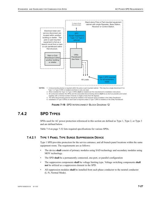
STANDARDS AND GUIDELINES FOR COMMUNICATION SITES AC POWER SPD REQUIREMENTS Electrical meter and service disconnect are located within another building or shelter. The pole or pad mounted equipment is fed as a branch circuit from a main or sub panelboard within that structure. NOTES: Main or Sub Panelboard within another building or shelter 7.4.2 SPD TYPES To Alarms Panel (Recommended) SPD (Surge Suppressor) Type 1 or Type 2 optional Utility Panelboard See Note 1 All Loads Stand alone Pole or Pad mounted equipment cabinet with single Repeater, Base Station, Receiver or Control Station. 1. A disconnecting device is required within the pole or pad mounted cabinet. This may be a single disconnect if no Type 1 or Type 2 SPD is installed and there is only one load. 2. When installed the Type 1or Type 2 SPDs shall be installed per the manufacturer's installation instructions. 3. All conductors between the SPDs and the associated disconnecting device shall be as short as possible and routed together with a minimal number of bends or angles of less than 90 degrees. 4. The SPD disconnecting devices should be installed in the topmost space available in the Utility Panelboard. 6. Installation of Type 3 SPDs on each load is required unless a Type 1 SPD is installed on the Utility Panelboard. FIGURE 7-18 SPD INTERCONNECT BLOCK DIAGRAM ‘Q’ SPDs used for AC power protection referenced in this section are defined as Type 1, Type 2, or Type 3 and are defined below. Table 7-4 on page 7-32 lists required specifications for various SPDs. 7.4.2.1 TYPE 1 PANEL TYPE SURGE SUPPRESSION DEVICE Type 3 SPD required for all equipment loads Type 1 SPD provides protection for the service entrance, and all branch panel locations within the same equipment room. The requirements are as follows: • The device shall consist of primary modules using SAD technology and secondary modules using MOV technology. • The SPD shall be a permanently connected, one-port, or parallel configuration • The suppression components shall be voltage limiting type. Voltage switching components shall not be utilized as a suppression element in the SPD. • All suppression modules shall be installed from each phase conductor to the neutral conductor (L-N, Normal Mode). 68P81089E50-B 9/1/05 7-27
- Page 285 and 286: STANDARDS AND GUIDELINES FOR COMMUN
- Page 287 and 288: STANDARDS AND GUIDELINES FOR COMMUN
- Page 289 and 290: STANDARDS AND GUIDELINES FOR COMMUN
- Page 291 and 292: STANDARDS AND GUIDELINES FOR COMMUN
- Page 293 and 294: STANDARDS AND GUIDELINES FOR COMMUN
- Page 295 and 296: STANDARDS AND GUIDELINES FOR COMMUN
- Page 297 and 298: STANDARDS AND GUIDELINES FOR COMMUN
- Page 299 and 300: STANDARDS AND GUIDELINES FOR COMMUN
- Page 301 and 302: STANDARDS AND GUIDELINES FOR COMMUN
- Page 303 and 304: STANDARDS AND GUIDELINES FOR COMMUN
- Page 305 and 306: STANDARDS AND GUIDELINES FOR COMMUN
- Page 307 and 308: STANDARDS AND GUIDELINES FOR COMMUN
- Page 309 and 310: STANDARDS AND GUIDELINES FOR COMMUN
- Page 311 and 312: CHAPTER 7 SURGE PROTECTIVE DEVICES
- Page 313 and 314: STANDARDS AND GUIDELINES FOR COMMUN
- Page 315 and 316: STANDARDS AND GUIDELINES FOR COMMUN
- Page 317 and 318: STANDARDS AND GUIDELINES FOR COMMUN
- Page 319 and 320: STANDARDS AND GUIDELINES FOR COMMUN
- Page 321 and 322: STANDARDS AND GUIDELINES FOR COMMUN
- Page 323 and 324: STANDARDS AND GUIDELINES FOR COMMUN
- Page 325 and 326: STANDARDS AND GUIDELINES FOR COMMUN
- Page 327 and 328: STANDARDS AND GUIDELINES FOR COMMUN
- Page 329 and 330: STANDARDS AND GUIDELINES FOR COMMUN
- Page 331 and 332: STANDARDS AND GUIDELINES FOR COMMUN
- Page 333 and 334: STANDARDS AND GUIDELINES FOR COMMUN
- Page 335: STANDARDS AND GUIDELINES FOR COMMUN
- Page 339 and 340: STANDARDS AND GUIDELINES FOR COMMUN
- Page 341 and 342: STANDARDS AND GUIDELINES FOR COMMUN
- Page 343 and 344: STANDARDS AND GUIDELINES FOR COMMUN
- Page 345 and 346: STANDARDS AND GUIDELINES FOR COMMUN
- Page 347 and 348: STANDARDS AND GUIDELINES FOR COMMUN
- Page 349 and 350: STANDARDS AND GUIDELINES FOR COMMUN
- Page 351 and 352: STANDARDS AND GUIDELINES FOR COMMUN
- Page 353 and 354: STANDARDS AND GUIDELINES FOR COMMUN
- Page 355 and 356: STANDARDS AND GUIDELINES FOR COMMUN
- Page 357 and 358: STANDARDS AND GUIDELINES FOR COMMUN
- Page 359 and 360: STANDARDS AND GUIDELINES FOR COMMUN
- Page 361 and 362: STANDARDS AND GUIDELINES FOR COMMUN
- Page 363 and 364: CHAPTER 8 MINIMIZING SITE INTERFERE
- Page 365 and 366: STANDARDS AND GUIDELINES FOR COMMUN
- Page 367 and 368: STANDARDS AND GUIDELINES FOR COMMUN
- Page 369 and 370: STANDARDS AND GUIDELINES FOR COMMUN
- Page 371 and 372: STANDARDS AND GUIDELINES FOR COMMUN
- Page 373 and 374: CHAPTER 9 EQUIPMENT INSTALLATION 9
- Page 375 and 376: STANDARDS AND GUIDELINES FOR COMMUN
- Page 377 and 378: STANDARDS AND GUIDELINES FOR COMMUN
- Page 379 and 380: STANDARDS AND GUIDELINES FOR COMMUN
- Page 381 and 382: STANDARDS AND GUIDELINES FOR COMMUN
- Page 383 and 384: STANDARDS AND GUIDELINES FOR COMMUN
- Page 385 and 386: STANDARDS AND GUIDELINES FOR COMMUN
STANDARDS AND GUIDELINES FOR COMMUNICATION SITES AC POWER SPD REQUIREMENTS<br />
Electrical meter <strong>and</strong><br />
service disconnect are<br />
located within another<br />
building or shelter. The<br />
pole or pad mounted<br />
equipment is fed as a<br />
branch circuit from a main<br />
or sub panelboard within<br />
that structure.<br />
NOTES:<br />
Main or Sub<br />
Panelboard within<br />
another building<br />
or shelter<br />
7.4.2 SPD TYPES<br />
To Alarms Panel<br />
(Recommended)<br />
SPD<br />
(Surge Suppressor)<br />
Type 1 or Type 2<br />
optional<br />
Utility<br />
Panelboard<br />
See Note 1<br />
All Loads<br />
St<strong>and</strong> alone Pole or Pad mounted equipment<br />
cabinet with single Repeater, Base Station,<br />
Receiver or Control Station.<br />
1. A disconnecting device is required within the pole or pad mounted cabinet. This may be a single disconnect if no<br />
Type 1 or Type 2 SPD is installed <strong>and</strong> there is only one load.<br />
2. When installed the Type 1or Type 2 SPDs shall be installed per the manufacturer's installation instructions.<br />
3. All conductors between the SPDs <strong>and</strong> the associated disconnecting device shall be as short as possible <strong>and</strong> routed<br />
together with a minimal number of bends or angles of less than 90 degrees.<br />
4. The SPD disconnecting devices should be installed in the topmost space available in the Utility Panelboard.<br />
6. Installation of Type 3 SPDs on each load is required unless a Type 1 SPD is installed on the Utility Panelboard.<br />
FIGURE 7-18 SPD INTERCONNECT BLOCK DIAGRAM ‘Q’<br />
SPDs used <strong>for</strong> AC power protection referenced in this section are defined as Type 1, Type 2, or Type 3<br />
<strong>and</strong> are defined below.<br />
Table 7-4 on page 7-32 lists required specifications <strong>for</strong> various SPDs.<br />
7.4.2.1 TYPE 1 PANEL TYPE SURGE SUPPRESSION DEVICE<br />
Type 3 SPD required<br />
<strong>for</strong> all equipment<br />
loads<br />
Type 1 SPD provides protection <strong>for</strong> the service entrance, <strong>and</strong> all branch panel locations within the same<br />
equipment room. The requirements are as follows:<br />
• The device shall consist of primary modules using SAD technology <strong>and</strong> secondary modules using<br />
MOV technology.<br />
• The SPD shall be a permanently connected, one-port, or parallel configuration<br />
• The suppression components shall be voltage limiting type. Voltage switching components shall<br />
not be utilized as a suppression element in the SPD.<br />
• All suppression modules shall be installed from each phase conductor to the neutral conductor<br />
(L-N, Normal Mode).<br />
68P81089E50-B 9/1/05 7-27


