Fan coil Aermec Omnia UL N Installation manual
Fan coil Aermec Omnia UL N Installation manual
Fan coil Aermec Omnia UL N Installation manual

You also want an ePaper? Increase the reach of your titles
YUMPU automatically turns print PDFs into web optimized ePapers that Google loves.
MANUALE D’USO E INSTALLAZIONE<br />
USE AND INSTALLATION MANUAL<br />
MANUEL D’UTILISATION ET D’INSTALLATION<br />
BEDIENUNGS- UND INSTALLATIONSANLEITUNG<br />
MANUAL DE INSTRUCCIONES E INSTALACIÓN<br />
VENTILCONVETTORE PER INSTALLAZIONE UNIVERSALE<br />
CON TERMOSTATO ELETTRONICO<br />
FAN COIL FOR UNIVERSAL INSTALLATION<br />
WITH ELECTRONIC THERMOSTAT<br />
VENTILO-CONVECTEUR POUR INSTALLATION UNIVERSELLE<br />
MUNI DE THERMOSTAT ÉLECTRONIQUE<br />
GEBLÄSEKONVEKTOR FÜR UNIVERSELLEN EINBAU<br />
MIT ELEKTRONISCHEM THERMOSTAT<br />
FAN COIL PARA INSTALACIÓN UNIVERSAL<br />
CON TERMOSTATO ELECTRÓNICO<br />
<strong>Omnia</strong> <strong>UL</strong> N<br />
<strong>Omnia</strong> <strong>UL</strong> 11 N<br />
<strong>Omnia</strong> <strong>UL</strong> 16 N<br />
<strong>Omnia</strong> <strong>UL</strong> 26 N<br />
<strong>Omnia</strong> <strong>UL</strong> 36 N<br />
I<strong>UL</strong>NLJ 1002 - 6976415_00<br />
Sostituisce il Replace Remplace le n° Ersetzt Sustituye a: 4528500_01 / 0809
OSSERVAZIONI<br />
Conservare i <strong>manual</strong>i in luogo asciutto, per evitare il deterioramento,<br />
per almeno 10 anni per eventuali riferimenti futuri.<br />
Leggere attentamente e completamente tutte le informazioni<br />
contenute in questo <strong>manual</strong>e. Prestare particolarmente<br />
attenzione alle norme d’uso accompagnate dalle scritte<br />
“PERICOLO” o “ATTENZIONE” in quanto, se non osservate,<br />
possono causare danno alla macchina e/o a persone e cose.<br />
Per anomalie non contemplate da questo <strong>manual</strong>e, interpellare<br />
tempestivamente il Servizio Assistenza di zona.<br />
REMARKS<br />
Store the <strong>manual</strong>s in a dry location to avoid deterioration, as<br />
they must be kept for at least 10 years for any future reference.<br />
All the information in this <strong>manual</strong> must be carefully read and<br />
understood. Pay particular attention to the operating standards<br />
with “DANGER” or “WARNING” signals as failure to comply<br />
with them can cause damage to the machine and/or persons or<br />
objects.<br />
If any malfunctions are not included in this <strong>manual</strong>, contact the<br />
local After-sales Service immediately.<br />
REMARQUES<br />
Conserver les manuels dans un endroit sec, afin d’éviter leur<br />
détérioration, pendant au moins 10 ans, pour toutes éventuelles<br />
consultations futures.<br />
Lire attentivement et entièrement toutes les informations contenues<br />
dans ce manuel. Prêter une attention particulière aux<br />
normes d’utilisation signalées par les inscriptions “DANGER”<br />
ou “ATTENTION”, car leur non observance pourrait causer un<br />
dommage à l’appareil et/ou aux personnes et objets.<br />
Pour toute anomalie non mentionnée dans ce manuel, contacter<br />
aussitôt le service après-vente de votre secteur.<br />
HINWEISE<br />
Bewahren Sie die Gebrauchsanleitungen mindestens<br />
10 Jahre für eventuelles zukünftiges<br />
Nachschlagen an einem trockenen Ort auf.<br />
Alle in diesem Handbuch enthaltenen Informationen aufmerksam<br />
und vollständig lesen. Insbesondere auf die<br />
Benutzungsanweisungen mit den Hinweisen "VORSICHT" oder<br />
"ACHTUNG" achten, da deren Nichtbeachtung Schäden am<br />
Gerät bzw. Sach- und Personenschäden zur Folge haben kann.<br />
Bei Betriebsstörungen, die in dieser Gebrauchsanweisung nicht<br />
aufgeführt sind, wenden Sie sich umgehend an die zuständige<br />
Kundendienststelle.<br />
OBSERVACIONES<br />
Guarde los <strong>manual</strong>es en un lugar seco para evitar su deterioro,<br />
al menos durante 10 años, por si fuera posible consultarlos en<br />
el futuro.<br />
Leer atenta y completamente todas las informaciones contenidas<br />
en este <strong>manual</strong>. Preste particular atención a las normas de uso<br />
acompañadas de las indicaciones “PELIGRO” o “ATENCIÓN”<br />
puesto que, si no se cumplen, pueden causar el deterioro de la<br />
máquina y/o daños personales y materiales.<br />
En caso de anomalías no contempladas en este <strong>manual</strong>, contacte<br />
inmediatamente con el Servicio de Asistencia de su zona.<br />
El aparato debe ser instalado de manera que haga posibles las<br />
L'apparecchio deve essere installato in maniera tale da rendere<br />
possibili operazioni di manutenzione e/o riparazione.<br />
La garanzia dell'apparecchio non copre in ogni caso i costi<br />
dovuti ad autoscale, ponteggi o altri sistemi di elevazione che si<br />
rendesero necessari per effettuare gli interventi in garanzia.<br />
AERMEC S.p.A. declina ogni responsabilità per qualsiasi danno<br />
dovuto ad un uso improprio della macchina, ad una lettura<br />
parziale o superficiale delle informazioni contenute in questo<br />
<strong>manual</strong>e.<br />
Il numero di pagine di questo <strong>manual</strong>e è: 92<br />
The apparatus must be installed in such a way that maintenance<br />
and/or repair operations are possible.<br />
The apparatus's warranty does not in any case cover costs due<br />
to automatic ladders, scaffolding or other lifting systems necessary<br />
for carrying out repairs under guarantee.<br />
AERMEC S.p.A. declines all responsibility for any damage<br />
whatsoever caused by improper use of the machine, and a partial<br />
or superficial acquaintance with the information contained<br />
in this <strong>manual</strong>.<br />
The number of pages in this <strong>manual</strong> is : 92<br />
Lors de l'installation de l'appareil, il faut prévoir l'espace<br />
nécessaire pour les opérations d'entretien et/ou de réparation.<br />
La garantie de l'appareil ne couvre pas les coûts dérivant de<br />
l'utilisation de voitures avec échelle mécanique, d'échafaudages<br />
ou d'autres systèmes de levée employés pour effectuer des interventions<br />
en garantie.<br />
AERMEC S.p.A. décline toute responsabilité pour tout dommage<br />
dû à une utilisation impropre de l’appareil et à une lecture<br />
partielle ou superficielle des informations contenues dans ce<br />
manuel.<br />
Ce manuel se compose de pages: 92<br />
Das Gerät so aufstellen, dass Instandhaltungs- und/oder<br />
Reparaturarbeiten durchgeführt werden können.<br />
Die Garantie des Gerätes deckt in keinem Fall Kosten für<br />
Feuerwehrleitern, Gerüste oder andere Hebesysteme ab, die<br />
sich für die Garantiearbeiten als erforderlich erweisen sollten.<br />
Die AERMEC S.p.A. übernimmt keine Haftung für Schäden aus<br />
dem unsachgemäßen Gebrauch des Gerätes und der teilweisen<br />
oder oberflächlichen Lektüre der in diesem Handbuch enthaltenen<br />
Informationen.<br />
Die Seitenanzahl diese Handbuches ist: Nr. 92 Seiten<br />
operaciones de mantenimiento y/o reparación.<br />
En cualquier caso, la garantía del aparato no cubre los costes<br />
derivados del uso de escaleras automáticas, andamios u otros<br />
sistemas de elevación necesarios para efectuar las intervenciones<br />
en garantía.<br />
AERMEC S.p.A. declina cualquier responsabilidad por cualquier<br />
daño debido a un uso impropio de la máquina, o bien a una<br />
lectura parcial o superficial de las informaciones contenidas en<br />
este <strong>manual</strong>.<br />
Número de páginas de este <strong>manual</strong>:92
INDICE<br />
DICHIARAZIONE DI CONFORMITÀ<br />
DECLARATION OF CONFORMITY<br />
DÉCLARATION DE CONFORMITÉ<br />
KONFORMITÄTSERKLÄRUNG<br />
DECLARACIÓN DE CONFORMIDAD<br />
Trasporto Simboli di sicurezza<br />
Transport Safety symbols<br />
Transport Symboles de sécurité<br />
Transport Sicherheitssymbole<br />
Transporte Símbolos de seguridad<br />
Italiano<br />
English<br />
Français<br />
Deutsche<br />
Español<br />
Dimensioni<br />
Dimensions<br />
Dimensions<br />
Abmessungen<br />
Dimensiones<br />
Schema elettrico<br />
Wiring diagrams<br />
Schémas électriques<br />
Schaltschemas<br />
Esquemas eléctricos<br />
4<br />
5<br />
6<br />
22<br />
38<br />
54<br />
70<br />
86<br />
88
AERMEC S.p.A.<br />
I-37040 Bevilacqua (VR) Italia – Via Roma, 996<br />
Tel. (+39) 0442 633111<br />
Telefax (+39) 0442 93730 – (+39) 0442 93566<br />
www .aermec. com - info @aermec. com<br />
DICHIARAZIONE DI CONFORMITÀ<br />
Noi, fi rmatari della presente, dichiariamo sotto la nostra esclusiva responsabilità,<br />
che il prodotto:<br />
VENTILCONVETTORE<br />
serie <strong>Omnia</strong> <strong>UL</strong> N<br />
al quale questa dichiarazione si riferisce è conforme alle seguenti norme<br />
armonizzate:<br />
- CEI EN 60335-2-40<br />
- CEI EN 55014-1<br />
- CEI EN 55014-2<br />
- CEI EN 61000-6-1<br />
- CEI EN 61000-6-2<br />
- CEI EN 61000-6-3<br />
- CEI EN 61000-6-4<br />
soddisfando così i requisiti essenziali delle seguenti direttive:<br />
- Direttiva LVD 2006/95/CE<br />
- Direttiva compatibilità elettromagnetica EMC2004/108/CE<br />
OMNIA <strong>UL</strong> N CON ACCESSORI<br />
E’ fatto divieto di mettere in servizio il prodotto dotato di accessori non di<br />
fornitura <strong>Aermec</strong>.<br />
CERTIFICAT DE CONFORMITÉ<br />
Nous soussignés déclarons sous notre exclusive responsabilité que le produit:<br />
VENTILO-CONVECTEURS<br />
série <strong>Omnia</strong> <strong>UL</strong> N<br />
auquel cette déclaration fait référence, est conforme aux normes harmonisées<br />
suivantes:<br />
- EN 60335-2-40<br />
- EN 55014-1<br />
- EN 55014-2<br />
- CEI EN 61000-6-1<br />
- CEI EN 61000-6-2<br />
- CEI EN 61000-6-3<br />
- CEI EN 61000-6-4<br />
satisfaisant ainsi aux conditions essentielles des directives suivantes:<br />
- Directive LVD 2006/95/CE<br />
- Directive compatibilité électromagnétique EMC2004/108/CE<br />
OMNIA <strong>UL</strong> N PLUS ACCESSOIRES<br />
Il est interdit de faire fonctionner l'appareil avec des accessoires qui ne<br />
sont pas fournis de <strong>Aermec</strong>.<br />
DECLARACIÓN DE CONFORMIDAD<br />
Los que suscriben la presente declaran bajo la propia y exclusiva<br />
responsabilidad que el conjunto en objeto, defi nido como sigue:<br />
FAN COIL<br />
serie <strong>Omnia</strong> <strong>UL</strong> N<br />
al que esta declaración se refi ere, está en conformidad a las siguientes<br />
normas armonizadas:<br />
- EN 60335-2-40<br />
- EN 55014-1<br />
- EN 55014-2<br />
- CEI EN 61000-6-1<br />
- CEI EN 61000-6-2<br />
- CEI EN 61000-6-3<br />
- CEI EN 61000-6-4<br />
- EN 61000-6-3<br />
al que esta declaración se refi ere, está en conformidad a las siguientes<br />
normas armonizadas:<br />
- Directiva LVD 2006/95/CE<br />
- Directiva compatibilidad electromagnétic EMC2004/108/CE<br />
OMNIA <strong>UL</strong> N CON ACCESORIOS<br />
Está prohibido poner en marcha el producto con accesorios no<br />
suministrados por <strong>Aermec</strong>.<br />
<strong>Omnia</strong> <strong>UL</strong> N<br />
CONFORMITY DECLARATION<br />
We the undersigned declare, under our own exclusive responsibility, that<br />
the product:<br />
FAN COIL<br />
<strong>Omnia</strong> <strong>UL</strong> N series<br />
to which this declaration refers, complies with the following standardised<br />
regulations:<br />
- EN 60335-2-40<br />
- EN 55014-1<br />
- EN 55014-2<br />
- CEI EN 61000-6-1<br />
- CEI EN 61000-6-2<br />
- CEI EN 61000-6-3<br />
- CEI EN 61000-6-4<br />
thus meeting the essential requisites of the following directives:<br />
- Directive LVD 2006/95/CE<br />
- EMC Electromagnetic Compatibility Directive 2004/108/CE<br />
OMNIA <strong>UL</strong> N WITH ACCESSORIES<br />
It is not allowed to use the unit equipped with accessories not supplied<br />
by <strong>Aermec</strong>.<br />
KONFORMITÄTSERKLÄRUNG<br />
Wir, die hier Unterzeichnenden, erklären auf unsere ausschließlich Verantwortung,<br />
dass das Produkt:<br />
GEBLÄSEKONVEKTOR<br />
der Serie <strong>Omnia</strong> <strong>UL</strong> N<br />
auf das sich diese Erklärung bezieht, den folgenden harmonisierten Normen<br />
entspricht:<br />
- EN 60335-2-40<br />
- EN 55014-1<br />
- EN 55014-2<br />
- CEI EN 61000-6-1<br />
- CEI EN 61000-6-2<br />
- CEI EN 61000-6-3<br />
- CEI EN 61000-6-4<br />
womit die grundlegenden Anforderungen folgender Richtlinien erfüllt werden:<br />
- Richtlinie LVD 2006/95/CE<br />
- Richtlinie zur elektromagnetischen Verträglichkeit EMC2004/108/CE<br />
OMNIA <strong>UL</strong> N + ZUBEHÖR<br />
Falls das Gerät mit Zubehörteilen ausgerüstet wird, die nicht von<br />
<strong>Aermec</strong> geliefert werden, ist dessen Inbetriebnahme solange untersagt.<br />
Bevilacqua, 11/01/2010 La Direzione Commerciale – Sales and Marketing Director<br />
Luigi Zucchi
TRASPORTO CARRIAGE TRANSPORT TRANSPORT TRANSPORTE<br />
NON bagnare Do NOT wet<br />
CRAINT l’humidité Vor Nässe schützen<br />
NO mojar<br />
6<br />
NON calpestare Do NOT trample<br />
NE PAS marcher sur cet emballage Nicht betreten<br />
NO pisar<br />
Sovrapponibilità: controllare sull’imballo la sovrapponibilità per conoscere il<br />
numero di macchine impilabili.<br />
Stacking: control the packing for the arrow position to know the number of<br />
machines that can be stacked.<br />
Superposabilité: contrôler sur l’emballage la superposabilité pour connaître le<br />
nombre de machines empilables.<br />
Stapelbarkeit: Auf der Verpackung kontrollieren, wie viele Maschinen gestapelt<br />
werden können.<br />
Posibilidad de superposición: controlar en el embalaje la posibilidad de superposición<br />
para saber cuántas máquinas se pueden apilar.<br />
NON lasciare gli imballi sciolti durante il trasporto.<br />
Do NOT leave loose packages during transport.<br />
ATTACHER les emballages pendant le transport.<br />
Die Verpackungen nicht ungesichert transportieren.<br />
NO lleve las cajas sueltas durante el transporte.<br />
NON trasportare la macchina da soli se il suo peso supera i 35 Kg.<br />
DO NOT handle the machine alone if its weight is over 35 Kg.<br />
NE PAS transporter tout seul l’appareil si son poids dépasse 35 Kg.<br />
Das Gerät NICHT alleine tragen, wenn sein Gewicht 35 Kg überschreitet.<br />
NO maneje los equipos en solitario si pesan más de 35 kg.<br />
SIMBOLI DI SICUREZZA SAFETY SYMBOL SIMBOLES DE SECURITE<br />
SICHERHEITSSYMBOLE SÍMBOLOS DE SEGURIDAD<br />
35Kg<br />
Pericolo: Pericolo: Pericolo!!!<br />
Tensione Organi in movimento<br />
Danger: Danger: Danger!!!<br />
Power supply Movings parts<br />
Danger: Danger: Danger!!!<br />
Tension Organes en mouvement<br />
Gefahr ! Gefahr ! Gefahr!!!<br />
Spannung Rotierende Teile<br />
Peligro: Peligro: Peligro!!!<br />
Tensión Elementos en movimiento
Congratulations on your purchase of the <strong>Aermec</strong> OMNIA <strong>UL</strong>_N fan <strong>coil</strong>.<br />
Made with materials of superior quality in strict compliance with safety regulations, "OMNIA <strong>UL</strong>_N" is easy to<br />
use and will have a long life.<br />
CONTENTS<br />
Important information Package<br />
Maintenance Troubleshooting<br />
Control panel functions<br />
Use<br />
Visualisations for the user<br />
Operation<br />
Description Technical data and operating limits<br />
Correction factors for operation with glycol water<br />
Main components Description of components<br />
<strong>Installation</strong> information<br />
Unit installation Coil rotation<br />
Water connections<br />
Condensate discharge connections<br />
Connection for air delivery in an adjacent room<br />
Electrical wirings<br />
Connections to the electronic card Network settings<br />
Dip-switch settings Filter installation and replacement<br />
Dimensions<br />
Wiring diagrams<br />
22<br />
I<strong>UL</strong>NIJ 1001 - 4528500_01<br />
23<br />
24<br />
25<br />
26<br />
27<br />
28<br />
30<br />
31<br />
32<br />
33<br />
34<br />
35<br />
36<br />
37<br />
86<br />
88
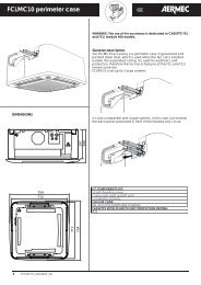
IMPORTANT INFORMATION<br />
WARNING: OMNIA fan <strong>coil</strong>s<br />
are designed for indoor use.<br />
WARNING: the fan <strong>coil</strong> is connected<br />
to power supply and<br />
water circuit. Operations performed<br />
by persons without the<br />
required technical skills can lead<br />
to personal injury to the operator<br />
or damage to the unit and surrounding<br />
objects.<br />
WARNING: components sensitive<br />
to static electricity may be<br />
destroyed by discharge notably<br />
lower than those at the human<br />
perception threshold. These discharges<br />
form when you touch a<br />
component or electric contact of<br />
a unit, without first discharging<br />
accumulated static electricity<br />
from your body. The damage<br />
caused to the unit by an overvoltage<br />
is not immediately evident - it<br />
only appears after a certain period<br />
of operation.<br />
STATIC ELECTRICITY ACCUM<strong>UL</strong>ATION<br />
Any person not connected in a conductive<br />
manner with the electronic<br />
potential of his surrounding environment<br />
can accumulate electrostatic<br />
charges.<br />
STANDARD PROTECTION AGAINST<br />
ELECTROSTATIC CHARGES<br />
Earthing quality<br />
When working with units sensitive<br />
to electrostatic electricity,<br />
ensure that people, workplaces<br />
and unit casings are correctly<br />
earthed. This will prevent the formation<br />
of electrostatic charges.<br />
Avoid direct contact<br />
Only touch the element exposed<br />
to electrostatic risk when absolutely<br />
essential (e.g. for maintenance).<br />
Touch the element without coming<br />
into contact with either the<br />
contact pins or the wire guides. If<br />
PACKAGE<br />
The fan <strong>coil</strong>s are shipped in standard<br />
package which consists of<br />
you follow this rule, the energy<br />
of the electrostatic charges cannot<br />
reach or damage the sensitive<br />
parts.<br />
Before taking measurements on the<br />
unit, it is necessary to discharge<br />
all electrostatic charges from your<br />
body: to do this, just touch an<br />
earthed metal object. Only use<br />
earthed measuring instruments.<br />
POWER THE FAN COIL ONLY WITH<br />
230V, SINGLE-PHASE VOLTAGE<br />
Any other type of power supply could<br />
permanently damage the fan <strong>coil</strong>.<br />
DO NOT USE THE FAN COIL<br />
IMPROPERLY<br />
Do not use the fan <strong>coil</strong> for animal<br />
husbandry applications (e.g.<br />
incubation).<br />
AIR THE ROOM<br />
Periodically air the room in which<br />
the fan <strong>coil</strong> has been installed. This<br />
is particularly important if the room<br />
is occupied by many people, or if<br />
gas appliances or sources of odours<br />
are present.<br />
ADJUST TEMPERATURE ADEQUATELY<br />
The room temperature should be<br />
adjusted in order to provide maximum<br />
comfort to the people in the<br />
room, especially if they are elderly,<br />
children or sick people; avoid differences<br />
over 7°C between the outdoor<br />
temperature and the temperature<br />
inside the room in summer.<br />
In summer, a temperature that is too<br />
low causes higher electrical consumption.<br />
CORRECTLY ADJUST THE AIR JET<br />
Air coming out from the fan <strong>coil</strong><br />
must not reach people directly; in<br />
fact, even if the air is warmer than<br />
the room temperature, it could<br />
cause a cold sensation and result<br />
in discomfort.<br />
DURING OPERATION<br />
Always leave the filter fitted on<br />
the fan <strong>coil</strong> during operation<br />
expanded polystyrene foam and<br />
cardboard shells.<br />
(otherwise dust in the air could<br />
soil the <strong>coil</strong> surface area).<br />
WHAT IS NORMAL<br />
In the cooling operation, water<br />
vapour may be present in the air<br />
delivery of the fan <strong>coil</strong>.<br />
In the heating operation, a slight<br />
hiss might be heard close to the<br />
fan <strong>coil</strong>. Sometimes the fan <strong>coil</strong><br />
might give off unpleasant smells<br />
due to the accumulation of substances<br />
present in the air of the<br />
room (clean the filter more often,<br />
especially if the room is not ventilated<br />
regularly).<br />
While the unit is functioning, there<br />
could be noises and creaks inside<br />
the device due to the various thermal<br />
expansions of the elements<br />
(plastic and metal), but this does<br />
not indicate any malfunction and<br />
does not damage the unit unless<br />
the maximum input water temperature<br />
is exceeded.<br />
MALFUNCTIONING<br />
In the event of a malfunction, cut<br />
off power supply to the unit, then<br />
restore the power and start the<br />
unit again. If the problem occurs<br />
again, call the local After-Sales<br />
Service immediately.<br />
DO NOT TUG THE ELECTRIC CABLE<br />
It is very dangerous to pull,<br />
tread on or crush the electric<br />
power cable, or fix it with nails or<br />
drawing pins.<br />
A damaged power cable can<br />
cause short circuits and injure<br />
people.<br />
DO NOT OBSTRUCT THE AIR<br />
OUTLETS BY PLACING<br />
OBJECTS INTO THEM<br />
Do not put anything in the air outlet<br />
slots.<br />
This could injure people and damage<br />
the fan.<br />
I<strong>UL</strong>NIJ 1001 - 4528500_01<br />
23
MAINTENANCE<br />
ROUTINE MAINTENANCE<br />
Routine maintenance can be carried<br />
out by the user: it involves a series<br />
of simple operations, thanks to<br />
which the fan <strong>coil</strong> can operate at<br />
its maximum efficiency level.<br />
Interventions:<br />
- External cleaning, weekly to be<br />
carried out with a moist cloth<br />
and neutral soap; do not use<br />
other detergents and solvents of<br />
any type.<br />
- cleaning the electrostatically precharged<br />
filter, every two weeks<br />
or weekly if the installation is in a<br />
very dusty environment, remove<br />
the dust that has accumulated<br />
with a vacuuming device, washing<br />
with running water and neutral<br />
soap is allowed but it speeds<br />
up the deterioration of the electrostatic<br />
precharge; do not use<br />
other detergents and solvents of<br />
any type.<br />
- Replacement of the electrostatically<br />
precharged filter every<br />
two years. Failure to make this<br />
replacement in the time specified<br />
means the end of the filter-<br />
TROUBLESHOOTING<br />
PROBLEM<br />
Insufficient air<br />
flow at outlet<br />
Unit does not heat<br />
Unit does not cool<br />
<strong>Fan</strong> not turning<br />
Condensation forming<br />
on the external case of<br />
the unit<br />
24<br />
I<strong>UL</strong>NIJ 1001 - 4528500_01<br />
ing of the microdusts because<br />
the electrostatic precharge has<br />
run out; the filtering capacity<br />
will be compared with that of a<br />
normal filter.<br />
- Visual inspection of the state of the<br />
fan <strong>coil</strong> for every maintenance<br />
operation; every fault must be<br />
communicated to the After Sales<br />
Service department.<br />
EXTRAORDINARY MAINTENANCE<br />
Extraordinary maintenance can<br />
only be performed by <strong>Aermec</strong><br />
After-Sales Services or by people<br />
with the technical and professional<br />
requisites qualifying them<br />
to undertake installation, conversion,<br />
expansion and maintenance<br />
of the systems and are able to<br />
check them in terms of safety and<br />
functionality, in particular with<br />
regard to electrical connections<br />
the following tests are required<br />
relative to:<br />
- Measurement of the electrical system<br />
insulation resistance;<br />
- Continuity of the protection wires.<br />
Extraordinary maintenance consists<br />
of a set of complex operations that<br />
PROBABLE CAUSE<br />
Incorrect speed setting on control panel<br />
Blocked filter<br />
Obstructed air flow (inlet and/or outlet)<br />
No hot water<br />
Incorrect control panel setting<br />
No cold water<br />
Incorrect control panel setting<br />
No electrical power<br />
Water has not reached operating temperature.<br />
Temperature and humidity limits specified by<br />
“MINIMUM AVERAGE WATER TEMPERATURE”<br />
have been reached<br />
For any problems not listed, contact the After Sales Service immediately.<br />
involve the dismantling of the fan<br />
<strong>coil</strong> or its components, resulting<br />
in the restoration of the fan <strong>coil</strong>'s<br />
functioning at maximum efficiency.<br />
Interventions:<br />
- Internal cleaning, annually or<br />
before shutting down for long<br />
periods; cleaning can be more<br />
frequent in environments where<br />
a high degree of air cleaning is<br />
required; it consists of cleaning<br />
the <strong>coil</strong>, the removable volute,<br />
the fan fins, the basin and all<br />
the parts in contact with the<br />
treated air.<br />
- Repairs and fine tuning: if you<br />
notice anomalies, consult the<br />
“TROUBLESHOOTING" chapter<br />
of this <strong>manual</strong> before contacting<br />
the After Sales Service.<br />
SOLUTION<br />
Select the correct speed on the control<br />
panel<br />
Clean the filter<br />
Remove the obstacle<br />
Check the boiler<br />
Set the control panel<br />
Check the chiller<br />
Set the control panel<br />
Check that there is electrical power<br />
Check heater or chiller.<br />
Check thermostat setting<br />
Raise the water temperature above the<br />
limits specified by “MINIMUM AVER-<br />
AGE WATER TEMPERATURE”
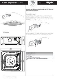
CONTROL PANEL FUNCTIONS<br />
– (B) Temperature selector<br />
– (C) Operation mode<br />
indicator light<br />
RED - BLUE - FUCHSIA<br />
Temperature<br />
standard<br />
configuration<br />
(dead band 5°C)<br />
Temperature<br />
optional<br />
configuration<br />
(dead band 2°C)<br />
20°C<br />
25°C<br />
12°C 28°C<br />
17°C<br />
C D C D<br />
20°C<br />
Ventilation is only allowed with the<br />
fin open; it must be <strong>manual</strong>ly opened.<br />
The closure of the fin causes ventilation<br />
to switch off.<br />
To access the control panel, lift the<br />
protection flap.<br />
Closing the master fan <strong>coil</strong> fin, the<br />
electronic thermostat card and the<br />
other fan <strong>coil</strong>s in the network will<br />
carry on working.<br />
(B)<br />
(C)<br />
22°C<br />
12°C 28°C<br />
14°C<br />
C D C D<br />
-<br />
HEATING COOLING<br />
HEATING COOLING<br />
+<br />
AUX<br />
(D)<br />
(A)<br />
33°C<br />
30°C<br />
– (D) Ventilation request<br />
indicator light<br />
YELLOW<br />
– (A) Ventilation speed selector:<br />
OFF The anti-freeze function<br />
is active<br />
AUTO Automatic ventilation<br />
mode<br />
Manual ventilation speed<br />
selection<br />
V1 = Minimum speed<br />
V2 = Average speed<br />
V3 = Maximum speed<br />
AUX Minimum speed<br />
Special accessories enabling,<br />
consult the relative <strong>manual</strong>s.<br />
I<strong>UL</strong>NIJ 1001 - 4528500_01<br />
FROST PROTECTION<br />
12°C<br />
12°C 12°C<br />
C D<br />
FROST PROTECTION:<br />
12°C<br />
12°C 12°C<br />
C D<br />
25
USE<br />
Starting<br />
- To start up the fan <strong>coil</strong>, turn the knob and choose a ventilation speed.<br />
- To switch off the fan <strong>coil</strong>, turn the knob to the OFF position.<br />
- OFF The fan <strong>coil</strong> is switched off.<br />
In the OFF condition, the thermostat carries on working.<br />
If the room temperature falls below 7°C, and the system conditions allow it,<br />
the thermostat will activate ventilation (anti-freeze function).<br />
Selecting the ventilation speed<br />
- AUTO The thermostat maintains the set temperature by automatically changing the<br />
ventilation speed on the basis of the room temperature and the set temperature.<br />
- The thermostat maintains the set temperature by means of ON-OFF cycles, using the<br />
minimum fan speed.<br />
- The thermostat maintains the set temperature by means of ON-OFF cycles, using the<br />
average fan speed.<br />
- The thermostat maintains the set temperature by means of ON-OFF cycles, using the<br />
maximum fan speed.<br />
Selecting the temperature<br />
- To increase the room temperature, turn the knob to the right (+).<br />
- To reduce the room temperature, turn the knob to the left (-).<br />
The temperatures are not indicated on the panel because, on one single knob position, the<br />
value changes in line with the operating mode (Heating, Cooling or Anti-freeze).<br />
The maximum and minimum temperature differences compared with the central position are +8°C<br />
and -8°C; only with the anti-freeze function is the set temperature fixed throughout the field.<br />
The temperature with the selector set in the central position is:<br />
Heating 20°C<br />
Cooling 25°C (standard configuration with dead band 5°C)<br />
Anti-freeze: the minimum room temperature is 7°C in all selector positions (the 12°C set<br />
activates automatically)<br />
Season changeover<br />
Water side changeover: the thermostat automatically sets Heating or Cooling operation according to the temperature<br />
of the water in the system.<br />
Air side changeover: for special settings, the season change function can be set by operating the temperature selector.<br />
26<br />
I<strong>UL</strong>NIJ 1001 - 4528500_01<br />
AUX
INDICATOR LIGHTS FOR THE USER (STANDARD CONFIGURATION)<br />
LED D indicates a ventilation request:<br />
YELLOW - (ON) The ambient conditions require the use of the fan (when the speed<br />
selector is on AUTO, V1, V2, V3)<br />
- (OFF) The ambient conditions do not require the use of the fan, or the<br />
selector is in the OFF (standby) position, or the fin is closed<br />
- (slow flashing) Operation mode managed by the centralised system. The<br />
fan selector on the panel is automatically blocked.<br />
- (quick flashing) Indicates an ambient probe fault<br />
(contact the After Sales Service)<br />
LED C indicates the active operating mode:<br />
RED - Heating<br />
- Quick flashing indicates that the Anti-freeze (Frost Protection) function is active<br />
RED + FUCHSIA - Heating. The alternate flashing colours indicate the absence of suitable<br />
conditions for enabling ventilation (unsuitable water temperature, or<br />
closed fin on versions with motorised fin).<br />
BLUE - Cooling<br />
BLUE + FUCHSIA - Cooling. The alternate flashing colours indicate the absence of suitable<br />
conditions for enabling ventilation (unsuitable water temperature, or<br />
closed fin on versions with motorised fin).<br />
Special visualisations following particular operating conditions:<br />
(these visualisations can be interpreted by the After Sales Service)<br />
BLUE + YELLOW - Slow flashing of the BLUE LED (C) and the YELLOW LED (D).<br />
Addressing procedure in progress. Turn the ventilation speed selector knob<br />
to activate the automatic procedure to assign the address to the unit.<br />
The thermostat functions are temporarily disabled.<br />
FUCHSIA + BLUE + RED Visualisation of the unit's serial address<br />
- The number of flashes of the FUCHSIA LED indicates the units.<br />
- The number of flashes of the BLUE LED indicates the tens.<br />
- The number of flashes of the RED LED indicates the hundreds.<br />
FUCHSIA + YELLOW - Slow contemporary flashing of the YELLOW LED and the FUCHSIA LED<br />
indicates the absence of communication between the control panel and the<br />
thermostat.<br />
SET POINT - AN EXAMPLE OF A SETTING<br />
Set Point<br />
I<strong>UL</strong>NIJ 1001 - 4528500_01<br />
C<br />
D<br />
AUX<br />
27
OPERATION<br />
The OMNIA <strong>UL</strong>_N fan <strong>coil</strong> concentrates<br />
hi-tech and highly functional features<br />
that make it the ideal means of climate<br />
control in every room.<br />
OMNIA fan <strong>coil</strong>s are designed for<br />
indoor use.<br />
The supply of climate-controlled air is<br />
immediate and distributed throughout<br />
the room. OMNIA <strong>UL</strong>_N generates<br />
heat if inserted in a heating system with<br />
boiler or heat pump, but it can also be<br />
used in summer as an air conditioner if<br />
the heating system has a water chiller.<br />
The quality of the treated air is guaranteed<br />
by a special, electrostatically<br />
pre-charged filter which absorbs and<br />
holds back the suspended dust particles.<br />
With the fan <strong>coil</strong> switched off,<br />
the closed fin prevents any dust or foreign<br />
bodies from entering.<br />
The removable drip tray and fan volute<br />
Description of the <strong>UL</strong>_N fan <strong>coil</strong> functions<br />
Type of system<br />
The OMNIA <strong>UL</strong>_N fan <strong>coil</strong>s are<br />
designed for 2-pipe systems and are<br />
configured:<br />
- without valve;<br />
- with 2-way valve or water probe<br />
downstream from the valve;<br />
- with 3-way valve and water probe<br />
downstream from the valve;<br />
Operation in TTL network<br />
The OMNIA <strong>UL</strong>_N “master” is fitted<br />
with an electronic card with microprocessor,<br />
able to manage a network of<br />
a further 5 fan <strong>coil</strong>s over a maximum<br />
network length of 30 metres. The settings<br />
(or set points) of the panel on the<br />
main fan <strong>coil</strong> (master) are received by<br />
the other fan <strong>coil</strong>s (slaves) which will<br />
operate autonomously.<br />
The OMNIA <strong>UL</strong> fan <strong>coil</strong> with slave<br />
function must be fi tted with the electronic<br />
card with microprocessor VMF-<br />
E0 or VMF-E1 (an accessory).<br />
All the fan <strong>coil</strong>s of the TTL network must<br />
have the same type of confi guration.<br />
Example: all standard, all with purifi<br />
ers (Plasmacluster and/or germicidal<br />
lamps), or all with an additional <strong>coil</strong><br />
(electric or with water).<br />
The slave fan <strong>coil</strong>s work with the settings<br />
dictated by the master fan <strong>coil</strong>.<br />
On the basis of the settings received<br />
from the network and the ambient<br />
conditions detected by the probes, the<br />
electronic card on each single slave<br />
fan <strong>coil</strong> acts (independently from the<br />
other fan <strong>coil</strong>s) to switch the ventilation<br />
on and off in order to create the<br />
conditions requested by the user for<br />
that specifi c room.<br />
Cooling operation<br />
Cooling operation requires a water cir-<br />
28<br />
I<strong>UL</strong>NIJ 1001 - 4528500_01<br />
ensure thorough cleaning of the unit<br />
(by specifically trained personnel),<br />
essential for installations in venues subject<br />
to crowding or in those with special<br />
hygiene requirements.<br />
The quietness of the new centrifugal<br />
fan assembly is such that at normal<br />
speeds of use you cannot hear when<br />
the OMNIA <strong>UL</strong>_N cuts in. The use of<br />
the electronic control panel avoids the<br />
annoying noise typical of mechanical<br />
thermostats.<br />
The control panel is protected by a flap<br />
on the head.<br />
OMNIA <strong>UL</strong>_N is equipped with an electronic<br />
control panel with microprocessor.<br />
It's extremely intuitive and userfriendly,<br />
with just two knobs - one to<br />
increase or decrease the temperature,<br />
and the other to switch on/off and set<br />
the ventilation speed.<br />
cuit with chiller.<br />
Heating operation<br />
Heating operation requires a water circuit<br />
with boiler, heat pump or solar<br />
system.<br />
Changeover (seasonal change)<br />
The thermostat automatically selects the<br />
operating mode (Heating/Cooling), if<br />
that mode is permitted (water probe<br />
and settings).<br />
- Normal band: heating at 39°C; cooling<br />
at 17°C.<br />
- Reduced band: heating at 35°C; cooling<br />
at 22°C.<br />
- Dead band: can be selected at 5°C or 2°C.<br />
Water side changeover<br />
- Water temperature checks<br />
Enabling of water side ventilation (only<br />
active with water temperature probe).<br />
The thermostat identifies the ventilation<br />
enabling threshold in Heating mode<br />
(minimum controlled) and Cooling<br />
mode (maximum controlled); with the<br />
dip-switches it is possible to choose<br />
between two temperature bands.<br />
Air side changeover<br />
If the actual room temperature is lower<br />
than the set point by a value equal to<br />
the dead band, there is an automatic<br />
swap to Heating operation.<br />
If the actual room temperature is higher<br />
than the set point by a value equal to<br />
the dead band, there is an automatic<br />
swap to Cooling operation.<br />
In the fan <strong>coil</strong> networks, the values of<br />
the dead band are only those configured<br />
on the master fan <strong>coil</strong><br />
Pause due to power failure<br />
After a power failure, the unit restarts<br />
with the settings that were active prior<br />
to the pause.<br />
The settings made on the control panel<br />
can be transmitted (without additional<br />
interfaces) to a network with up to<br />
5 fan <strong>coil</strong>s, all equipped with their<br />
own electronic card. The fan <strong>coil</strong>s in<br />
the network will each adapt their own<br />
operation to the environmental conditions<br />
detected in that specific room.<br />
The OMNIA <strong>UL</strong>_N fan <strong>coil</strong> has been<br />
designed to meet all system requirements,<br />
thanks also to its wide range of<br />
accessories.<br />
Easy installation with reversible hydraulic<br />
connections during installation.<br />
Full compliance with accident prevention<br />
regulations.<br />
Routine maintenance is reduced to<br />
periodic air filter cleaning with a<br />
vacuum cleaner.<br />
Delayed start-up<br />
The unit can begin ventilation some<br />
time after start-up - usually up to 2’40”<br />
(pre-heating function).<br />
Anti-freeze protection<br />
Commands on OFF position. The fan<br />
<strong>coil</strong> can restart in heating mode (setting<br />
12°C) if the room temperature<br />
falls below 7°C and the temperature of<br />
the water in the system is suitable.<br />
In the fan <strong>coil</strong> networks, the slave fan<br />
<strong>coil</strong>s can activate the anti-freeze protection<br />
regardless of the settings on the<br />
master fan <strong>coil</strong>.<br />
If the anti-freeze protection is active on<br />
the master fan <strong>coil</strong>, all the other slave fan<br />
<strong>coil</strong>s will also adopt a setting of 12°C,<br />
regardless of their ambient conditions.<br />
Room temperature probe<br />
If the room temperature probe on the<br />
slave fan <strong>coil</strong>s is faulty, the temperature<br />
will be measured by the probe of<br />
the master.<br />
Ventilation<br />
3-speed ventilation can be commanded<br />
both <strong>manual</strong>ly and automatically.<br />
- Manual, with the selector on V1, V2<br />
and V3. The fan is used with ON-OFF<br />
cycles at the selected speed.<br />
- Automatic, with the selector on<br />
AUTO. The fan speed is managed by<br />
the thermostat, on the basis of the<br />
ambient conditions and the fan <strong>coil</strong><br />
configuration.<br />
Thermostat settings:<br />
- 3-level thermostat, with the selector<br />
on AUTO. The fan maintains the speed<br />
relating to one of the three predetermined<br />
steps, depending on the difference<br />
between room temperature and<br />
set point. Once it has reached the set<br />
point, the fan will switch off.
- Modulated output thermostat, with<br />
the selector on AUTO. The fan makes<br />
cycles, alternating the speeds according<br />
to the difference between room temperature<br />
and set point. Once it has reached<br />
the set point, the fan will switch off. This<br />
setting is not compatible with continuous<br />
ventilation management.<br />
Ventilation management<br />
Ventilation settings:<br />
- Continuous ventilation. Ventilation<br />
is always active. The temperature is<br />
controlled by intercepting the flow<br />
of water to the fan <strong>coil</strong>. This function<br />
requires the presence of a water valve<br />
(accessory), and cannot be activated<br />
simultaneously with the "modulated<br />
output thermostat" option.<br />
- Thermostat-controlled ventilation.<br />
Ventilation switches off when the set<br />
temperature is reached (set point).<br />
Valve adjustment logics<br />
With the Thermostat-controlled ventilation<br />
or Modulated output thermostat<br />
setting, the valve is managed with the<br />
following logics:<br />
- Heating - the valve is managed to<br />
exploit the stack effect of the fan <strong>coil</strong>,<br />
and to provide heat even with the<br />
fan switched off. These settings also<br />
reduce the number of valve openings<br />
and closings; with hot water circulating<br />
in the fan <strong>coil</strong>, a request from the<br />
thermostat will produce ventilation<br />
immediately.<br />
- Cooling - to make the best use of the<br />
unit's cooling capacity and perform a<br />
more accurate check on the room temperature,<br />
the valve opening does not<br />
coincide with ventilation.<br />
Water probe<br />
There is a water temperature probe in<br />
the heat exchanger of the unit.<br />
The slave fan <strong>coil</strong> can work without the<br />
water probe: if it is absent or faulty,<br />
the temperature will be measured by<br />
the master probe along. In this case,<br />
ventilation is always enabled on the<br />
slave fan <strong>coil</strong>.<br />
The water temperature probe can be<br />
With valve<br />
positioned downstream or upstream<br />
from the shutoff valve, so also the dipswitches<br />
on the card must be set. The<br />
difference lies in the management of the<br />
ventilation of the fan <strong>coil</strong>s with valve.<br />
Setting the dip-switch as a probe downstream<br />
of the valve, ventilation startup<br />
(changeover) is dependent on the<br />
temperature of the air in the room.<br />
Setting the dip-switch as a probe<br />
upstream of the valve, ventilation startup<br />
is dependent on the temperature<br />
of the water in the system. With this<br />
setting, the pre-heating function is activated,<br />
and there is a ventilation start-up<br />
delay of between 0” and 2’40”.<br />
To position the bulb on the delivery<br />
pipe upstream of the valve, the standard<br />
water probe must be replaced<br />
with the SW3N probe accessory.<br />
External contact<br />
The card offers the possibility of a connection<br />
with an external contact. With<br />
a closed external contact, the unit is<br />
configured as in the thermostat OFF<br />
position (except when the thermostat<br />
is in the Anti-freeze Protection position<br />
or when the ambient probe is absent<br />
or faulty). This contact can be used<br />
to manage inputs such as a remote<br />
ON-OFF command, a presence sensor,<br />
a window contact, a faulty circulation<br />
pump signal, etc.<br />
In fan <strong>coil</strong> networks, only the external<br />
contact of the master fan <strong>coil</strong> is<br />
enabled. If the master input is closed,<br />
all the slave fan <strong>coil</strong>s of the network<br />
are switched off.<br />
Microswitch contact<br />
The card offers the possibility of a connection<br />
with the Microswitch contact<br />
located on the delivery fins. With the<br />
fins closed, the fan <strong>coil</strong> is 100% OFF.<br />
In fan <strong>coil</strong> networks, when the fin of<br />
the master fan <strong>coil</strong> is closed, ventilation<br />
stops but the electronic thermostat<br />
card and the other fan <strong>coil</strong>s in the network<br />
carry on working.<br />
Emergency operation<br />
In the event of a faulty probe, the elec-<br />
tronic card can automatically detect the<br />
problem and enable an emergency program<br />
to avoid any inconvenience for<br />
the user, who is immediately informed<br />
of the fault (LED indicator lights).<br />
Ambient probe correction<br />
To obtain a better room temperature<br />
adjustment, the thermostat applies<br />
special algorithms to correct the ambient<br />
probe installed on the fan <strong>coil</strong>; the<br />
probe is in contact with the housing,<br />
and is therefore influenced by it.<br />
The dynamic correction is a correction<br />
algorithm of the ambient probe which<br />
takes into account the particular operation<br />
status of the fan <strong>coil</strong> in any one<br />
moment. More precisely, there are two<br />
possible cases of dynamic correction:<br />
- Dynamic correction A: in the case<br />
of systems without a valve (or with<br />
a downstream probe), the correction<br />
depends on the water and ambient<br />
temperatures.<br />
- Dynamic correction B: in the case of<br />
systems with a valve and an upstream<br />
probe, the correction depends on the<br />
valve and on the water and ambient<br />
temperatures. Unlike the previous correction,<br />
this one uses different time<br />
constants to calculate the appropriate<br />
correction (because the housing is<br />
influenced in a different way).<br />
Upstream water probe Downstream water probe<br />
Water probe present Water probe not fi tted Water probe present Water probe not fi tted<br />
Water side changeover Air side changeover Air side changeover Air side changeover<br />
Pre-heating delay Pre-heating delay No ventilation delay Pre-heating delay<br />
Minimum and maximum<br />
controls active<br />
No minimum and maximum<br />
control<br />
Minimum and maximum<br />
controls active<br />
I<strong>UL</strong>NIJ 1001 - 4528500_01<br />
No minimum and maximum<br />
control<br />
- Dynamic correction A: Fixed correction - Dynamic correction B: Fixed correction<br />
Water side changeover Air side changeover<br />
No ventilation delay No ventilation delay<br />
Without valve Confi guration not used<br />
Minimum and maximum No minimum and maximum<br />
controls active<br />
control<br />
- Dynamic correction B: Fixed correction<br />
29
DESCRIPTION OF THE UNIT<br />
AIM OF THE UNIT<br />
The fan <strong>coil</strong> is a room air treatment terminal unit for both winter and summer operation.<br />
<strong>Omnia</strong> <strong>UL</strong>_N version<br />
A fan <strong>coil</strong> with cabinet, for universal installation and fitted with a multifunction electronic thermostat. It can be installed as an<br />
autonomous unit or within a network: it can, in fact, manage a network of a further 5 fan <strong>coil</strong>s*.<br />
* The fan <strong>coil</strong>s within a network must be pre-arranged models, or equipped with the special accessories.<br />
AVAILABLE SIZES<br />
The <strong>Omnia</strong> <strong>UL</strong>_N fan <strong>coil</strong>s are available in 4 sizes.<br />
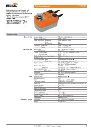
TECHNICAL DATA AND OPERATING LIMITS<br />
<strong>Omnia</strong> <strong>UL</strong> 11 N 16 N 26 N 36 N<br />
Heating output (water input 70°C)<br />
Cooling output (water input 7°C)<br />
Input power<br />
Input current<br />
Maximum water inlet temperature<br />
Maximum operating pressure<br />
Room temperature limits Ta<br />
Relative humidity limits in the room R.H.<br />
Protection rating<br />
Power supply<br />
Performance values refer to the following conditions:<br />
- at the maximum motor speed;<br />
Water temperature<br />
In order to prevent air stratification in the<br />
room, and therefore to achieve improved<br />
mixing, it is advisable not to supply the fan<br />
<strong>coil</strong> with water at a temperature over 65°C.<br />
Minimum average water temperature<br />
If the fan <strong>coil</strong> is working in continuous<br />
cooling mode in an environment<br />
where the relative humidity is high,<br />
condensate might form on the air<br />
delivery and on the outside of the<br />
device. This condensate might be<br />
30<br />
Minimum average water temperature [°C]<br />
Temperature with wet bulb<br />
of the air in the room<br />
I<strong>UL</strong>NIJ 1001 - 4528500_01<br />
[W] 2010 2910 4620 5940<br />
[W] 840 1200 2030 2830<br />
[W] 18 32 35 42<br />
[A] 0.09 0.15 0.18 0.22<br />
[°C] 80 80 80 80<br />
[bar] 8 8 8 8<br />
0°C < Ta < 40°C<br />
R.H. < 85%<br />
IP 20<br />
[V ~ Hz] 230V ( ±10%) ~ 50Hz<br />
The use of water at high temperatures<br />
could cause squeaking due to the different<br />
thermal expansions of the elements<br />
(plastic and metal), this does not however<br />
deposited on any objects underneath<br />
and on the floor.<br />
To avoid condensate on the external<br />
structure of the device while the fan is<br />
functioning, the average temperature of<br />
the water must not be lower than the<br />
- the total input power is determined by adding the input power<br />
for the unit and the input power for the accessories connected<br />
and declared in the corresponding <strong>manual</strong>s.<br />
cause damage to the unit if the maximum<br />
operating temperature is not exceeded.<br />
limits shown in the table below, that<br />
depend on the thermo-hygrometric conditions<br />
of the air in the room.<br />
These limits refer to unit operating with<br />
fan at minimum speed.<br />
Temperature of the air in the room with dry bulb<br />
21 23 25 27 29 31<br />
15 3 3 3 3 3 3<br />
17 3 3 3 3 3 3<br />
19 3 3 3 3 3 3<br />
21 6 5 4 3 3 3<br />
23 - 8 7 6 5 5
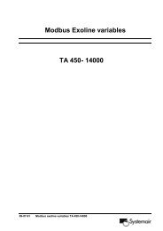
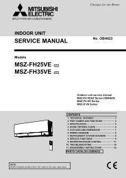
CORRECTION<br />
Key:<br />
FACTORS WHEN OPERATING USING GLYCOL WATER<br />
Correction factor<br />
Correction factor<br />
Correction factor<br />
1,2<br />
1,1<br />
1,0<br />
0,9<br />
0,8<br />
6 7 8 9 10 11 12 13 14 15 16 17 °C<br />
1,2<br />
1,1<br />
1,0<br />
0,9<br />
0,8<br />
0,7<br />
0,6<br />
6 7 8 9 10 11 12 13 14 15 16 17 °C<br />
1,6<br />
1,5<br />
1,4<br />
1,3<br />
1,2<br />
1,1<br />
1,0<br />
0,9<br />
0,8<br />
0,7<br />
0,6<br />
Pressure drops<br />
Air flow rate<br />
Output<br />
COOLING FUNCTION MODE HEATING FUNCTION MODE<br />
Medium glycol water temperature<br />
Medium glycol water temperature<br />
0,5<br />
6 7 8 9 10 11 12 13 14 15 16 17 18 °C<br />
Medium glycol water temperature<br />
GLYCOL WATER AT 10%<br />
Correction factor<br />
1,4<br />
1,3<br />
1,2<br />
1,1<br />
1,0<br />
0,9<br />
0,8<br />
30 40 50 60 70 80 90 °C<br />
GLYCOL WATER AT 20%<br />
Correction factor<br />
1,4<br />
1,3<br />
1,2<br />
1,1<br />
1,0<br />
0,9<br />
0,8<br />
30 40 50 60 70 80 90 °C<br />
GLYCOL WATER AT 35%<br />
Correction factor<br />
1,4<br />
1,3<br />
1,2<br />
1,1<br />
1,0<br />
0,9<br />
Medium glycol water temperature<br />
Medium glycol water temperature<br />
0,8<br />
30 40 50 60 70 80 90 °C<br />
Medium glycol water temperature<br />
I<strong>UL</strong>NIJ 1001 - 4528500_01<br />
31
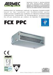
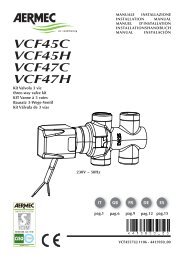
MAIN COMPONENTS<br />
1 Control panel (<strong>UL</strong> N)<br />
2 Electronic card<br />
3 Cabinet<br />
4 Feet (accessory ZU)<br />
5 Load-bearing structure<br />
6 Air filter<br />
OMNIA <strong>UL</strong>_N<br />
32<br />
10<br />
DESCRIPTION OF COMPONENTS<br />
CON TR OL PA NEL<br />
The control panel is housed in the head of<br />
the fan <strong>coil</strong>, protected by an access flap.<br />
ELECTRONIC THERMOSTAT<br />
OMNIA <strong>UL</strong>_N is equipped with an<br />
electronic control panel with microprocessor.<br />
It's extremely intuitive and<br />
user-friendly, with just two knobs - one<br />
to increase or decrease the temperature,<br />
and the other to switch on/off<br />
and set the predefined (or automatic)<br />
ventilation speeds.<br />
The response to commands may be<br />
delayed (heat exchanger pre-heating).<br />
THERMOSTAT ELECTRONIC CARD<br />
The box containing the thermostat electronic<br />
card is fixed to the side of the<br />
fan <strong>coil</strong>.<br />
The electronic card has a dip-switch<br />
for configuration, and connectors for<br />
making the connection with:<br />
- the power supply,<br />
- the earthing,<br />
- the control panel (user interface),<br />
- the fan motor command,<br />
- the valve command,<br />
- the room temperature probe,<br />
- the water temperature probe,<br />
- the fan <strong>coil</strong> network,<br />
- the external contact,<br />
- the MS external contact.<br />
HEAT EXCHANGE COIL<br />
2-row <strong>coil</strong> with copper pipe and aluminium<br />
fins, held in place by means<br />
of the mechanical expansion of the<br />
9<br />
I<strong>UL</strong>NIJ 1001 - 4528500_01<br />
8<br />
7<br />
6<br />
7 <strong>Fan</strong> motor<br />
8 <strong>Fan</strong><br />
9 Basin<br />
10 Heat exchange <strong>coil</strong><br />
11 Head with adjustable fins<br />
11<br />
5<br />
pipes. The collectors are fitted with<br />
female connections and air vents in<br />
the upper part of the <strong>coil</strong>. The <strong>coil</strong> can<br />
be rotated on the worksite.<br />
CABINET<br />
Casing in RAL9002<br />
The casing is made of galvanised steel, varnished<br />
with polyester powders to guarantee<br />
high resistance to rust and corrosion.<br />
The feet (accessory) are in plastic,<br />
colour RAL7044.<br />
ELECTROSTATICALLY PRECHARGED<br />
AIR FILTER<br />
Fire resistance Class 2 (<strong>UL</strong> 900).<br />
Easily extractible, it is supplied with the<br />
fan <strong>coil</strong> in a sealed box which should<br />
be opened only upon use. The electrostatically<br />
pre-charged filter combines<br />
the normal mechanical filtering of the<br />
air that passes through the filter, with<br />
an electrostatic attraction of powder<br />
that increases its filtering considerably.<br />
ELECTRIC FAN ASSEMBLY<br />
Applied directly to the frame, it consists<br />
of extremely quiet, compact, double<br />
suction centrifugal fans. The electrical<br />
motor, protected against overloading,<br />
has three speeds with the running<br />
capacitor always on, directly coupled<br />
with the fans and cushioned with flexible<br />
supports. The fan shrouds can be<br />
inspected (an operation that can only<br />
be carried out by personnel with the<br />
specific technical skills), which also<br />
means the inner parts can be accu-<br />
1<br />
2<br />
3<br />
4<br />
rately cleaned.<br />
LOAD-BEARING STRUCTURE<br />
Made of sheet metal of an adequate<br />
thickness, and galvanised to protect<br />
against oxidation. Equipped with<br />
closed cell thermal insulation with<br />
Class 1 fire resistance.<br />
Holes in the back for wall mounting.<br />
Each device is equipped with a condensate<br />
collection tray that can be<br />
removed for cleaning (this operation<br />
can only be carried out by personnel<br />
with the specific technical skills).<br />
CONDENSATE DISCHARGE<br />
Every device is fitted with a tray for collecting<br />
condensation, with a connection<br />
for draining condensation produced<br />
by the unit in cooling mode.<br />
WATER CONNECTIONS<br />
The connections, located on the left<br />
hand side, are female. The possibility<br />
exists for rotating the battery on the<br />
construction site. \.<br />
HEAD WITH ADJUSTABLE FINS<br />
Colour RAL7044<br />
With the deflector fin fully closed, the<br />
tripping of the microswitch stops ventilation<br />
thereby interrupting any further<br />
heat exchange with the environment.<br />
The control panel is also housed in the<br />
head, and is protected by a flap.
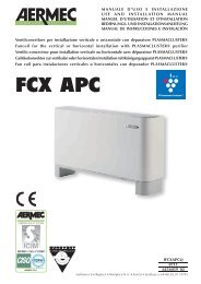
ELECTROSTATICALLY PRECHARGED AIR FILTER<br />
SA<br />
Fractional efficiency [%]<br />
SW<br />
50<br />
40<br />
30<br />
20<br />
10<br />
INSTALLATION<br />
WARNING: OMNIA fan <strong>coil</strong>s<br />
are designed for indoor use.<br />
WARNING: check that the power<br />
supply is disconnected before carrying<br />
out any procedures on the unit.<br />
WARNING: before carrying out<br />
any work, put the proper individual<br />
protection equipment on.<br />
WARNING: the device must be<br />
installed in compliance with national<br />
plant engineering rules.<br />
WARNING: the electrical<br />
connections, plus the installation of<br />
fan <strong>coil</strong>s and relevant accessories,<br />
should only be performed by a<br />
technician with the necessary<br />
technical and professional expertise to<br />
install, modify, extend and maintain<br />
systems, and who is able to check the<br />
systems for purposes of safety and<br />
correct operation (in this <strong>manual</strong> such<br />
technicians will be indicated with the<br />
general term "personnel with specific<br />
technical skills").<br />
In the specific case of electrical wirings,<br />
the following must be checked:<br />
- measurement of the electrical system<br />
SYSTEM EXAMPLES<br />
Key:<br />
0<br />
SW Water temperature sensor<br />
VCH Solenoid valve (Heating / Cooling)<br />
SA Room temperature sensor<br />
0<br />
AIR<br />
0,3 0,5 0,7<br />
Particle diameter [µm]<br />
1,0 2,0<br />
insulation strength.<br />
- continuity of the protection wires<br />
WARNING: Install a device, main<br />
switch, or electric plug so you can<br />
fully disconnect the device from the<br />
power supply.<br />
The essential indications to install the<br />
device correctly are given here.<br />
The installer's experience will be<br />
necessary however, to perfect all the<br />
operations in accordance with the<br />
specific requirements.<br />
The water, condensate discharge<br />
and electrical circuit ducts must be<br />
provided for.<br />
The fan <strong>coil</strong> should be installed in such<br />
a way as to facilitate routine (filter<br />
cleaning) and special maintenance<br />
operations, as well as access to the<br />
air drain valve on the side of the unit<br />
frame (connections side).<br />
Do not install the unit in rooms where<br />
there are inflammable gases or<br />
acid/alkaline substances which can<br />
provoke irreparable damage to the<br />
copper-aluminium heat exchangers or<br />
internal plastic components.<br />
Do not install the unit in workshops<br />
or kitchens, where oil vapours mixed<br />
SA<br />
SW<br />
AIR<br />
VCH<br />
= <strong>Aermec</strong> <strong>UL</strong> range filter<br />
= Standard filter for fan <strong>coil</strong>s<br />
with the treated air can be deposited<br />
on the exchange <strong>coil</strong>s (reducing their<br />
effectiveness) or on the internal parts<br />
of the unit (damaging the plastic<br />
components).<br />
The fan <strong>coil</strong> must be installed in such a<br />
position that the air can be distributed<br />
throughout the room and so that there<br />
are no obstacles (curtains or objects)<br />
to the passage of the air from the<br />
suction louvers.<br />
you are advised not to install the<br />
fan <strong>coil</strong> above objects that suffer<br />
from damp or wet because in some<br />
conditions condensation may form on<br />
the external frame of the equipment<br />
with the possibility of dripping or<br />
failures may occur in the hydraulic<br />
system and condensate drainage with<br />
the consequent spilling of liquid.<br />
The assembly site must be chosen in<br />
such a way that the maximum and<br />
minimum ambient temperature limits<br />
are respected 0-45°C (
UNIT INSTALLATION<br />
- Loosen the screws to remove the housing.<br />
- With wall-mounted units, keep a<br />
minimum clearance of 80mm from<br />
the floor. With floor-standing units on<br />
feet, refer to the instructions supplied<br />
with the accessory.<br />
- The supporting wall must be perfectly<br />
flat. For fixing, use 4 wall plugs (not<br />
INSTALLATION EXAMPLES<br />
34<br />
<strong>UL</strong>_N<br />
wall-mounted installation<br />
COIL ROTATION<br />
If the hydraulic connections require<br />
the rotation of the <strong>coil</strong>, remove the<br />
cabinet and ambient probe then<br />
proceed as follows:<br />
– remove the electrical connections<br />
from the terminal strip;<br />
– remove the probe from the <strong>coil</strong>;<br />
– remove the screws fixing the basin<br />
and remove it;<br />
– remove the screws securing the <strong>coil</strong>,<br />
then remove the <strong>coil</strong>;<br />
– remove the push-outs on the righthand<br />
side;<br />
– rotate the <strong>coil</strong> and secure it with the<br />
previously removed screws;<br />
– reassemble the tray, fixing it with the<br />
screws. All the trays are suitable for<br />
I<strong>UL</strong>NIJ 1001 - 4528500_01<br />
supplied) with suitable characteristics<br />
for the specific type of wall.<br />
- Apply any accessories.<br />
- To modify the settings of the<br />
electronic thermostat, adjust the dipswitches<br />
from the special inspection<br />
window in the box on the side (see<br />
“DIP-SWITCH SETTINGS”).<br />
<strong>UL</strong>_N<br />
wall-mounted installation with feet (ZU)<br />
condensate drainage on both sides;<br />
NB: before connecting the condensate<br />
discharge, use a tool to knock out the<br />
diaphragm of the tray on the water<br />
connections side.<br />
– position the polyethylene cap of the<br />
condensate discharge onto the lefthand<br />
side;<br />
– remove the electric motor cable from<br />
the right-hand side;<br />
– remove the rectangular push-out from<br />
the left-hand side;<br />
– recover the cable grommet and insert it<br />
in the left-hand side before closing the<br />
right-hand hole with adhesive tape;<br />
– move the electric motor cable onto<br />
the left-hand side, passing it through<br />
- Make all the connections.<br />
- Reassemble the casing.<br />
- Make sure the fan <strong>coil</strong> is working properly.<br />
- Assemble the air filter. It is supplied in<br />
a sealed box, to be opened only at the<br />
time of use.<br />
<strong>UL</strong>_N<br />
ceiling installation<br />
the cable grommet and arranging it so<br />
it reaches the connector on the side;<br />
– move the control panel from the right<br />
to the left of the head (the hole must be<br />
closed with the recovered plastic baffle);<br />
– unravel the twists and turns of the<br />
microswitch cable for the length<br />
necessary to reach the control board<br />
on the left-hand side;<br />
– fasten the microswitch cable to the<br />
cable clamps;<br />
– restore the electrical wirings between<br />
the control panel and control board.
CONNECTIONS<br />
The water, condensate discharge and electrical circuit ducts must be provided for.<br />
WATER CONNECTIONS<br />
- Make the water connections. To help<br />
the bleeding of air from the <strong>coil</strong>, you<br />
are advised to connect the water<br />
outlet pipe to the fitting at the top;<br />
any inversion will not jeopardise the<br />
proper functioning of the unit.<br />
AIR<br />
CONDENSATE DISCHARGE CONNECTION<br />
During cooling operation the indoor<br />
unit removes humidity from the air. The<br />
condensate water must be eliminated<br />
by connecting the appropriate<br />
discharge coupling to the piping of the<br />
condensate discharge system.<br />
NB: Before connecting the condensate<br />
discharge, use a tool to knock out the<br />
ELECTRICAL WIRINGS<br />
OMNIA<br />
WARNING: check that the power<br />
supply is disconnected before carrying<br />
out any procedures on the unit.<br />
In the specific case of electrical wirings,<br />
the following must be checked:<br />
- Measurement of the electrical system<br />
insulation strength<br />
- Continuity of the protection wires<br />
- The electrical wirings must be made in<br />
compliance with the wiring diagrams<br />
The unit must be connected directly<br />
to an electrical outlet or to an<br />
independent circuit.<br />
OMNIA fan <strong>coil</strong>s are powered with a<br />
current of 230V ~ 50Hz with an earth<br />
connection, but the line voltage must<br />
remain within the tolerance value of<br />
±10% compared with the nominal value.<br />
The electrical power cable must be of<br />
the H07 V-K or N07 V-K type with<br />
450/750V insulation if inside a tube<br />
or raceway. Use cables with double<br />
H5vv-F type insulation for visible<br />
cable installation. All the cables<br />
must be piped or ducted until they<br />
are inside the fan <strong>coil</strong>. The cables<br />
leaving the pipe or raceway must be<br />
D<br />
SC<br />
The position and diameter of the<br />
water connections are shown in the<br />
dimensions.<br />
You are advised to adequately<br />
insulate water lines, or fit the auxiliary<br />
condensate drain tray (available as an<br />
Coil connections<br />
<strong>Omnia</strong> <strong>UL</strong> 11 N 16 N 26 N 36 N<br />
Ø 1/2” 1/2” 1/2” 1/2”<br />
CONNECTIONS<br />
OUT = Water outlet <strong>coil</strong> connection<br />
IN = Water inlet <strong>coil</strong> connection<br />
AIR = Coil air drain valve<br />
D = Coil drainage valve<br />
SC = Condensate discharge (male Ø 16mm)<br />
diaphragm of the tray on the water<br />
connections side.<br />
Seal the unused drainage hole.<br />
The condensate drain network must<br />
be properly scaled and the piping<br />
situated in such a way as to keep<br />
an adequate slope along the route<br />
(min. 1%). If condensate is discharged<br />
positioned in such a way that there<br />
are not traction or twisting stresses<br />
and they are anyway protected from<br />
outside agents.<br />
Stranded cables can only be used with<br />
crimping terminals. Check the wire<br />
strands are well inserted.<br />
The wiring diagrams are subject to<br />
continuous updates, so it is essential<br />
to use those on the machine as your<br />
reference.<br />
For all the connections, follow the wiring<br />
diagrams supplied with the device and<br />
shown in this documentation.<br />
In installations with a 3-way valve, the<br />
minimum water temperature sensor<br />
must be relocated from its standard<br />
mounting in the <strong>coil</strong> assembly to the<br />
delivery hose upstream of the valve.<br />
If you need to relocate the water<br />
temperature probe, the standard probe<br />
must be replaced with an SW3N<br />
accessory probe, fitted with a cable of<br />
suitable length.<br />
The connections must be made with the<br />
connectors on the electronic card on<br />
the side of the fan <strong>coil</strong> (protected by a<br />
plastic box).<br />
accessory), to prevent dripping during<br />
the cooling function.<br />
Test the seal on the water<br />
connections.<br />
into the sewage system, install a<br />
siphon to prevent the return of<br />
unpleasant odours into the room.<br />
Test the condensate discharge seal.<br />
WARNING: the diagram showing<br />
the connections of the electronic card<br />
to the control board is printed inside<br />
its box cover.<br />
- Connect the power cables.<br />
- Connect the earth cable.<br />
- Connect the electric cables of the<br />
valve accessory (if installed).<br />
- Connect the network cables (if<br />
connected to a network).<br />
- Connect the cables for an external<br />
contact (if envisaged).<br />
- Check all the connections and relative<br />
cables are well fixed.<br />
I<strong>UL</strong>NIJ 1001 - 4528500_01<br />
35
CONNECTIONS TO THE ELECTRONIC CARD<br />
Connections key:<br />
L - N = Power supply<br />
230V AC - 50Hz<br />
Screw clamps<br />
Minimum cable section = 0.5mm2 Maximum cable section = 2.0mm2 = EARTH connection<br />
Screw clamp<br />
Minimum cable section = 0.5mm2 Maximum cable section = 2.0mm2 Y1 = VC/VF command<br />
Faston-type connector<br />
Y2 = Accessory command<br />
Faston-type connector<br />
N = Neutral<br />
Faston-type connector<br />
Minimum cable section = 0.5mm2 V3 = Motor command<br />
Maximum speed<br />
Faston-type connector<br />
Minimum cable section = 0.5mm2 Maximum cable section = 2.0mm2 V2 = Motor command<br />
Average speed<br />
Faston-type connector<br />
Minimum cable section = 0.5mm2 Maximum cable section = 2.0mm2 V1 = Motor command<br />
Minimum speed<br />
Faston-type connector<br />
Minimum cable section = 0.5mm2 Maximum cable section = 2.0mm2 FUSE = Protection fuse<br />
Delayed 2A fuse<br />
SA = SA Air probe<br />
Analogue input<br />
Removable-type connector<br />
Maximum cable length = 3m<br />
NETWORK SETTINGS<br />
TTL NETWORK<br />
- Consisting of up to 6 fan <strong>coil</strong>s (one<br />
master and 5 slaves)<br />
- Maximum line length 30m.<br />
The master fan <strong>coil</strong>s are equipped with<br />
a control panel and an electronic card<br />
with microprocessor which has outputs<br />
in order to be inserted in a TTL network.<br />
36<br />
<strong>Omnia</strong> <strong>UL</strong> _N<br />
-<br />
+<br />
TTL Line<br />
I<strong>UL</strong>NIJ 1001 - 4528500_01<br />
SP = Not present<br />
SW = Water probe<br />
Analogue input<br />
Faston-type connector<br />
Maximum cable length = 3m<br />
CE = External contact<br />
Digital input<br />
Screw clamps<br />
Minimum cable section = 0.2mm2 Maximum cable section = 1.0mm2 Maximum cable length = 100m<br />
<strong>Omnia</strong> <strong>UL</strong>_S + VMF E0<br />
/<br />
<strong>Omnia</strong> <strong>UL</strong>_S + VMF E1<br />
Max 30m<br />
he OMNIA <strong>UL</strong> fan <strong>coil</strong> with slave<br />
function must be fitted with the<br />
electronic card with microprocessor<br />
VMF-E0 or VMF-E1 (an accessory).<br />
All the fan <strong>coil</strong>s of the TTL network must<br />
have the same type of accessory.<br />
The settings (or set points) of the panel<br />
on the main fan <strong>coil</strong> (master) are<br />
MS = Microswitch<br />
Edge-type connector<br />
Control panel - TTL = Local serial TTL<br />
Removable-type connector<br />
Minimum cable section = 0.2mm2 Maximum cable section = 1.0mm2 Total maximum cable length = 30m<br />
(see the diagram showing the connections<br />
between the units)<br />
received by the other fan <strong>coil</strong>s (slaves).<br />
The units connected to the TTL network<br />
are automatically recognised (they<br />
require no confi guration procedure).
DIP-SWITCH SETTINGS<br />
Turn off the power to the unit.<br />
This operation should be carried out in the installation phase, by suitably trained and qualified personnel only.<br />
The dip-switches are on the electronic card. They can be used to obtain the following functions:<br />
Dip 1 (Default OFF)<br />
Water valve check:<br />
❑ Shutoff valve absent, OFF<br />
❑ Shutoff valve present, ON<br />
Dip 2 (Default OFF)<br />
Position of the water temperature probe:<br />
❑ Water temperature probe downstream of the shufoff<br />
valve, OFF<br />
❑ Water temperature probe upstream of the shufoff<br />
valve, ON<br />
Dip 3 (Default OFF)<br />
Ventilation control:<br />
❑ Thermostat-controlled ventilation, OFF<br />
❑ Continuous ventilation, ON *<br />
Dip 4 (Default OFF)<br />
Ventilation enabling:<br />
❑ Normal band enabling, OFF<br />
❑ Reduced band enabling, ON<br />
ON<br />
ON<br />
OFF<br />
ON<br />
1 2 3 4 5 6 7 8<br />
SW<br />
1 2 3 4 5 6 7 8<br />
SW<br />
Reduced band Dead band 2°C<br />
With shutoff valve<br />
ON<br />
ON<br />
ON<br />
ON<br />
ON<br />
1 2 3 4 5 6 7 8<br />
OFF<br />
1 2 3 4 5 6 7 8<br />
OFF<br />
1 2 3 4 5 6 7 8<br />
SW<br />
SW<br />
Dip 5 (Default OFF)<br />
Factory setting<br />
(reserved for accessory configuration)<br />
Dip 6 (Default OFF)<br />
Factory setting<br />
(reserved for accessory configuration)<br />
Dip 7 (Default OFF)<br />
Dead band:<br />
❑ Dead band 5°C, OFF<br />
❑ Dead band 2°C, ON<br />
Dip 8 (Default OFF)<br />
Thermostat settings:<br />
❑ 3-level thermostat, OFF<br />
❑ Modulated output thermostat, ON *<br />
❑ Adjust the chosen setting on the dip-switch<br />
SOME EXAMPLES:<br />
OMNIA <strong>UL</strong> N (default) Water probe upstream of the valve<br />
Continuous ventilation<br />
ON<br />
OFF<br />
INSTALLING THE ELECTROSTATICALLY PRECHARGED AIR FILTER<br />
<strong>Installation</strong><br />
- Remove the suction filter frame from<br />
the unit.<br />
- Use the tip of a tool to lever the inner<br />
hooks of the grille.<br />
- Remove the filter from its sealed package.<br />
- Insert the filter in the suction grille.<br />
- Reassemble the filter frame.<br />
- Insert the suction filter frame in the<br />
unit. Fire resistance<br />
* The Continuous Ventilation and Modulated Output Thermostat<br />
settings are not compatible.<br />
✗<br />
Characteristics<br />
Class 2 (<strong>UL</strong> 900).<br />
Easy to remove, it is supplied in a sealed<br />
box only to be opened when it is to<br />
be used.<br />
The electrostatic precharge of the<br />
filter is spent after two years of the<br />
box being opened, after this period it<br />
behaves like a normal filter.<br />
For this reason replacement over two<br />
years with a new one is recommended<br />
ON<br />
I<strong>UL</strong>NIJ 1001 - 4528500_01<br />
1 2 3 4 5 6 7 8<br />
SW<br />
SW<br />
ON<br />
OFF<br />
ON<br />
OFF<br />
(available as a spare part from <strong>Aermec</strong><br />
After Sales centres).<br />
Maintenance<br />
Cleaning frequently, removing<br />
the dust that has built up using<br />
a vacuum, the use of water and<br />
cleaning substances considerably<br />
speeds up the electrostatic precharge<br />
deterioration.<br />
37
DIMENSIONI DIMENSIONS ABMESSUNGEN DIMENSIONES [mm]<br />
86<br />
I<strong>UL</strong>NIJ 1001 - 4528500_01<br />
ZU<br />
Larghezza Width Largeur Breite Longitud<br />
Altezza Height Hauteur Höhe Altura<br />
Profondità Depth Profondeur Tiefe Profundidad<br />
Altezza zoccoli Height of feet Hauteur des pieds Höhe der Sockel Altura zócalos<br />
Peso* Weight* Poids* Gewicht* Peso *<br />
50mm<br />
100 mm<br />
50 mm<br />
<strong>UL</strong> 11N 16N 26N 36N<br />
A 640 750 980 1200<br />
H 606 606 606 606<br />
L 173 173 173 173<br />
Z 93 93 93 93<br />
[kg] 12,5 13,5 16,5 19,5<br />
* (ventilconvettore senza zoccoli) (fan <strong>coil</strong> without feet) (ventilo-convecteur sans pieds) (Gebläsekonvektor<br />
ohne Sockel) (fan <strong>coil</strong> sin zócalos)<br />
Attacchi batteria (femmina) Coil connections (female) Raccords de batterie<br />
(femelle) Anschlüsse Wärmetauscher (Innengewinde) Conexiones batería (hembra)<br />
Mod. <strong>UL</strong> 11N 16N 26N 36N<br />
2 R 1/2” 1/2” 1/2” 1/2”
DIMENSIONI DIMENSIONS ABMESSUNGEN DIMENSIONES [mm]<br />
10<br />
10<br />
E<br />
D<br />
6,5<br />
14,5<br />
6,5<br />
³80<br />
544<br />
264<br />
97<br />
31<br />
120<br />
120<br />
r49<br />
5<br />
72 29<br />
5<br />
5<br />
72<br />
26<br />
64<br />
65 54<br />
145 196<br />
A<br />
B<br />
C<br />
= =<br />
=<br />
D<br />
3<br />
=<br />
=<br />
C<br />
B<br />
A<br />
=<br />
80<br />
1<br />
5<br />
5<br />
4<br />
96 (ZU)<br />
5<br />
2<br />
93<br />
106<br />
148 (ZU) 10<br />
421<br />
1 Testata con alette orientabili<br />
2 Mobile di copertura<br />
3 Struttura portante<br />
4 Zoccolo <strong>UL</strong><br />
5 Spazio per i collegamenti<br />
1 Head with adjustable fins<br />
2 Cabinet<br />
3 Load-bearing structure<br />
4 Foot <strong>UL</strong><br />
5 Space for connections<br />
1 Tête avec ailettes orientables<br />
2 Carosserie de protection<br />
3 Structure porteuse<br />
4 Pied <strong>UL</strong><br />
5 Espace pour les connexions<br />
1 Kopfteil mit schwenkbaren<br />
Lamellen<br />
2 Abdeckung<br />
3 Trägerstruktur<br />
4 Sockel <strong>UL</strong><br />
5 Platz für die Anschlüsse<br />
1 Parte superior con aletas orientables<br />
2 Mueble de cobertura<br />
3 Estructura portante<br />
4 Zócalo <strong>UL</strong><br />
5 Espacio para las conexiones<br />
Mod. <strong>UL</strong> 11 <strong>UL</strong> 16 <strong>UL</strong> 26 <strong>UL</strong> 36<br />
A 640 750 980 1200<br />
B 384 494 725 945<br />
C 360,5 470,5 701,5 921,5<br />
D 288 398 629 849<br />
E 394 504 735 955<br />
La parete di supporto deve essere perfettamente piana, per il fissaggio usare 4 tasselli ad espansione con caratteristiche adeguate al tipo<br />
di parete (non forniti).<br />
The supporting wall must be perfectly flat. For fixing, use 4 wall plugs (not supplied) with suitable characteristics for the specific type of wall.<br />
Le mur de support doit être parfaitement plat ; pour la fixation, employer 4 chevilles à expansion (non fournies), ayant des caractéristiques<br />
aptes au type de mur.<br />
Die Stützwand muss absolut eben sein, für die Befestigung 4 Stück Erweiterungsdübeln (nicht im Lieferumfang enthalten) mit zum<br />
Wandtyp passenden Eigenschaften verwenden.<br />
La pared de sostén debe ser completamente plana, para fijar los 4 tacos de expansión (no suministrados), adecuados al tipo de pared.<br />
I<strong>UL</strong>NIJ 1001 - 4528500_01<br />
87
SCHEMI ELETTRICI WIRING DIAGRAMS SCHEMAS ELECTRIQUES ELEKTRISCHE SCHALTPLÄNE ESQUEMAS ELECTRICOS<br />
LEGENDA KEY LEGENDE LEGENDE LEYENDA<br />
IG = Interruttore generale Master switch Interrupteur général Hauptschalter Interruptor general<br />
M = Morsettiera Control board Bornier Klemmleiste Caja de conexiones<br />
MS = Microinterruttore Dip-switch Microrupteur Mikroschalter Microinterruptor<br />
MV = Motore ventilatore <strong>Fan</strong> motor Moteur du ventilateur Ventilatormotor Motor ventilador<br />
PE = Collegamento di terra Earth connection Mise à la terre Erdung Toma de tierra<br />
SA = Sonda ambiente Ambient probe Sonde ambiante Raumtemperaturfühler Sonda ambiente<br />
SC = Sonda ambiente Control card carte de contrôle Steuerplatine Tarjeta de control<br />
SW = Sonda minima temperatura acqua Minimum water temperature probe Sonde de température minimale de l'eau<br />
Sonde für Mindest-Wassertemperatur Sonda mínima temperatura del agua<br />
VCH = Valvola solenoide Solenoid valve Vanne solénoïde Magnetventil Válvula solenoide<br />
88<br />
= Componenti forniti optional Components supplied as optional extras Composants fournis en option<br />
Als Option lieferbare Teile Componentes opcionales facilitados<br />
= Collegamenti da eseguire in loco Connections to be made on site Branchements à effectuer sur les lieux<br />
Vor Ort auszuführende Anschlüsse Conexiones que realizar in situ<br />
OMNIA <strong>UL</strong> N<br />
T °C<br />
ON/VEL<br />
4<br />
3<br />
2<br />
1<br />
I<strong>UL</strong>NIJ 1001 - 4528500_01<br />
C7<br />
CN1<br />
IG<br />
T1<br />
L N<br />
L N<br />
230V 50Hz<br />
PE<br />
+<br />
CN7-B CN7-A<br />
Y2<br />
N<br />
Y1<br />
N<br />
C1<br />
CN27<br />
E0<br />
PF2<br />
VC/F<br />
1<br />
2- GND<br />
1-TX-RX<br />
CN17<br />
N V3 V2 V1<br />
MAX<br />
MED<br />
CN8<br />
MIN<br />
DIP<br />
CN9<br />
JP1<br />
CN11<br />
BL NE MA RO<br />
M<br />
MV 1<br />
10k<br />
Dis. 5152700_00<br />
Los esquemas eléctricos están sujetos a modificaciones continuas, por lo tanto es obligatorio tomar la referencia de los que se encuentran a bordo de la máquina.<br />
All wiring diagrams are constantly updated. Please refer to the ones supplied with the unit.<br />
Nos schémas électriques étant constamment mis à jour, il faut absolument se référer à ceux fournis à bord de nos appareils.<br />
Die Schaltpläne werden ständig aktualisiert, deswegen muss man sich stets auf das mit dem Gerät gelieferte Schaltschema beziehen.<br />
El cableado de las máquinas es sometido a actualizaciones constantes. Por favor, para cada unidad remitirse a los esquemas suministrados con la misma.<br />
MS<br />
CN10-B CN10-A<br />
CE 1<br />
(SP) 1<br />
ON<br />
SA<br />
SW<br />
1<br />
1 2 3 4 5 6 7 8<br />
SA<br />
SW<br />
10k
SCHEMI ELETTRICI WIRING DIAGRAMS SCHEMAS ELECTRIQUES ELEKTRISCHE SCHALTPLÄNE ESQUEMAS ELECTRICOS<br />
LEGENDA KEY LEGENDE LEGENDE LEYENDA<br />
AR = Arancio<br />
BI = Bianco<br />
BL = Blu<br />
GR = Grigio<br />
GV = Giallo-Verde<br />
MA = Marrone<br />
NE = Nero<br />
RO = Rosso<br />
OMNIA <strong>UL</strong> N<br />
AR = Orange<br />
BI = White<br />
BL = Blue<br />
GR = Grey<br />
GV = Yellow-green<br />
MA = Brown<br />
NE = Black<br />
RO = Red<br />
T °C<br />
ON/VEL<br />
4<br />
3<br />
2<br />
1<br />
Only master<br />
E0 Master<br />
C7<br />
CN1<br />
IG<br />
T1<br />
L N<br />
L N<br />
230V 50Hz<br />
AR = orange<br />
BI = blanc<br />
BL = bleu<br />
GR = gris<br />
GV = jaune-vert<br />
MA = marron<br />
NE = noir<br />
RO = rouge<br />
PE<br />
+<br />
CN7-B CN7-A<br />
Y2<br />
N<br />
Y1<br />
N<br />
C1<br />
CN27<br />
E0<br />
PF2<br />
VC/F<br />
1<br />
TTL<br />
2- GND<br />
1-TX-RX<br />
CN17<br />
AR = Orange<br />
BI = Weiß<br />
BL = Blau<br />
GR = Grau<br />
GV = Gelb/Grün<br />
MA = Braun<br />
NE = Schwarz<br />
RO = Rot<br />
(------------------------------------------------------30 m MAX-----------------------------------------------------------)<br />
N V3 V2 V1<br />
MAX<br />
MED<br />
MIN<br />
DIP<br />
CN9<br />
JP1<br />
CN11<br />
BL NE MA RO<br />
M<br />
MV 1<br />
10k<br />
Dis. 5152700_00<br />
CN8<br />
MS<br />
CN10-B CN10-A<br />
CE 1<br />
(SP) 1<br />
ON<br />
SA<br />
SW<br />
1 2 3 4 5 6 7 8<br />
SA<br />
SW<br />
10k<br />
I<strong>UL</strong>NIJ 1001 - 4528500_01<br />
1<br />
AR = Naranja<br />
BI = Blanco<br />
BL = Azul<br />
GR = Gris<br />
GV = Amarillo-Verde<br />
MA = Marrón<br />
NE = Negro<br />
RO = Rojo<br />
E0/1 Slave 1÷5<br />
Los esquemas eléctricos están sujetos a modificaciones continuas, por lo tanto es obligatorio tomar la referencia de los que se encuentran a bordo de la máquina.<br />
All wiring diagrams are constantly updated. Please refer to the ones supplied with the unit.<br />
Nos schémas électriques étant constamment mis à jour, il faut absolument se référer à ceux fournis à bord de nos appareils.<br />
Die Schaltpläne werden ständig aktualisiert, deswegen muss man sich stets auf das mit dem Gerät gelieferte Schaltschema beziehen.<br />
El cableado de las máquinas es sometido a actualizaciones constantes. Por favor, para cada unidad remitirse a los esquemas suministrados con la misma.<br />
89
<strong>Aermec</strong> partecipa al Programma di Certificazione EUROVENT. I prodotti interessati figurano nella Guida EUROVENT dei Prodotti Certificati.<br />
<strong>Aermec</strong> is partecipating in the EUROVENT Certification Programme. Products are as listed in the EUROVENT Directory of Certified Products.<br />
<strong>Aermec</strong> partecipe au Programme de Certification EUROVENT. Les produits figurent dans l’Annuaire EUROVENT des Produits Certifiés.<br />
<strong>Aermec</strong> ist am Zertifikations - Programm EUROVENT beteiligt. Die entsprechend gekennzeichneten Produkte sind im EUROVENT - Jahrbuch aufgefürt.<br />
AERMEC S.p.A. participa en el programa de certificación EUROVENT. Sus equipos aparecen en el directorio de productos certificados EUROVENT.<br />
I dati tecnici riportati nella presente documentazione non sono impegnativi.<br />
AERMEC S.p.A. si riserva la facoltà di apportare in qualsiasi momento tutte le modifiche ritenute necessarie per il miglioramento del prodotto.<br />
Les données mentionnées dans ce manuel ne constituent aucun engagement de notre part. <strong>Aermec</strong> S.p.A. se réserve le droit de modifier à tous moments les<br />
données considérées nécessaires à l’amelioration du produit.<br />
Technical data shown in this booklet are not binding.<br />
<strong>Aermec</strong> S.p.A. shall have the right to introduce at any time whatever modifications deemed necessary to the improvement of the product.<br />
Im Sinne des technischen Fortsschrittes behält sich <strong>Aermec</strong> S.p.A. vor, in der Produktion Änderungen und Verbesserungen ohne Ankündigung durchzuführen.<br />
ILos datos técnicos indicados en la presente documentación no son vinculantes.<br />
<strong>Aermec</strong> S.p.A. se reserva el derecho de realizar en cualquier momento las modificaciones que estime necesarias para mejorar el producto.<br />
AERMEC S.p.A.<br />
I-37040 Bevilacqua (VR) - Italia<br />
Via Roma, 996 - Tel. (+39) 0442 633111<br />
Telefax (+39) 0442 93730 - (+39) 0442 93566<br />
www .aermec. com<br />
I<strong>UL</strong>NIJ 1001 - 4528500_01