Fan coil Aermec Omnia UL S Installation manual
Fan coil Aermec Omnia UL S Installation manual
Fan coil Aermec Omnia UL S Installation manual

Create successful ePaper yourself
Turn your PDF publications into a flip-book with our unique Google optimized e-Paper software.
VENTILCONVETTORI<br />
FAN COIL<br />
VENTILO-CONVECTEURS<br />
GEBLÄSEKONVEKTOREN<br />
<strong>Omnia</strong> <strong>UL</strong> S<br />
ISO 9001 - Cert. n° 0128/4<br />
Sostituisce - Replace<br />
Remplace - Ersetzt:<br />
69764.51/0303<br />
I<strong>UL</strong>SLX<br />
0711<br />
6976451_01<br />
MMM AAA NNN UU AAA LL E D ’’ UU S O EEE II N S TTA LL LL A ZZ I OO NN EE DD I R EE CC TT I OO NN FFF O RR U S E A NN D II N S TA LL L AT III O NN<br />
MMMAANUUEL DE FFONCCTIONNNNEEMMMEEENNTT EETT DD’’INNSTTALLLLATTIIOONN BEDDDIIENNUUNGGG- UNNDD INNSTALLLAATIIONSAANNLEIITUUNNGG
INDICE • CONTENTS INDEX INHALTSVERZEICHN<br />
I<br />
GB<br />
F<br />
D<br />
INFORMAZIONI GENERALI GENERAL INFORMATION<br />
INFORMATIONS GENERALES ALLGEMEINE INFORMATIONEN 3<br />
Descrizione di <strong>Omnia</strong> <strong>UL</strong> S<br />
Utilizzo • Visualizzazioni Caratteristiche di funzionamento Imballo Installazione dell’unità 4<br />
Collegamenti elettrici Rotazione batteria 5<br />
Informazioni importanti e manutenzione 6<br />
Description of <strong>Omnia</strong> <strong>UL</strong> S<br />
Use Displays Operation Packaging <strong>Installation</strong> Electrical connections 7<br />
Coil rotation 8<br />
Important maintenance information 9<br />
Description de l’unité <strong>Omnia</strong> <strong>UL</strong> S<br />
Emploi Visualisation Caracteristiques de fonctionnement Emballage <strong>Installation</strong> de l’unité 10<br />
Connexions electriques Rotation batterie 11<br />
Informations importantes sur la maintenance 12<br />
Beschreibung des Gerätes <strong>Omnia</strong> <strong>UL</strong> S<br />
Anwendung Leuchtanzeigen Funktionseigenschaften Verpackung <strong>Installation</strong> der Einheit 13<br />
Elektrischer anschluss Umdrehen des Wärmetauschers 14<br />
Wichtige hinweise und wartung 15<br />
DATI DIMENSIONALI DIMENSIONS DIMENSIONS ABMESSUNGEN 16<br />
SCHEMA ELETTRICO WIRING DIAGRAM SCHEMAS ELECTRIQUES SCHALTPLANE 18<br />
MISURE DI SICUREZZA SAFETY MEASURES MISURES DE SECURITE SICHEREITSMAßNAHMEN 24<br />
SOLUZIONE DEI PROBLEMI REMEDY<br />
SOLUTION ABHILFE 25<br />
SERVIZIO ASSISTENZA TECNICA 27
AERMEC S.p.A.<br />
I-37040 Bevilacqua (VR) Italia – Via Roma, 44<br />
Tel. (+39) 0442 633111<br />
Telefax (+39) 0442 93566 – 0442 93730<br />
www .aermec. com - info @aermec. com<br />
DICHIARAZIONE DI CONFORMITÀ<br />
Noi, fi rmatari della presente, dichiariamo sotto la nostra esclusiva<br />
responsabilità, che il prodotto:<br />
VENTILCONVETTORE<br />
serie <strong>Omnia</strong> <strong>UL</strong><br />
al quale questa dichiarazione si riferisce è conforme alle seguenti norme<br />
armonizzate:<br />
- CEI EN 60335-2-40<br />
- CEI EN 55014-1<br />
- CEI EN 55014-2<br />
- CEI EN 61000-6-1<br />
- CEI EN 61000-6-3<br />
soddisfando così i requisiti essenziali delle seguenti direttive:<br />
- Direttiva LVD 2006/95/CE<br />
- Direttiva compatibilità elettromagnetica 2004/108/CE<br />
- Direttiva Macchine 98/37/CE<br />
OMNIA <strong>UL</strong> CON ACCESSORI<br />
E’ fatto divieto di mettere in servizio il prodotto dotato di accessori<br />
non di fornitura <strong>Aermec</strong>.<br />
CERTIFICAT DE CONFORMITÉ<br />
Nous soussignés déclarons sous notre exclusive responsabilité que le<br />
produit:<br />
VENTILO-CONVECTEURS<br />
série <strong>Omnia</strong> <strong>UL</strong><br />
auquel cette déclaration fait référence, est conforme aux normes<br />
harmonisées suivantes:<br />
- EN 60335-2-40<br />
- EN 55014-1<br />
- EN 55014-2<br />
- EN 61000-6-1<br />
- EN 61000-6-3<br />
satisfaisant ainsi aux conditions essentielles des directives suivantes:<br />
- Directive LVD 2006/95/CE<br />
- Directive compatibilité électromagnétique 2004/108/CE<br />
- Directive Machines 98/37/CE<br />
OMNIA <strong>UL</strong> PLUS ACCESSOIRES<br />
Il est interdit de faire fonctionner l'appareil avec des accessoires qui<br />
ne sont pas fournis de <strong>Aermec</strong>.<br />
DECLARACIÓN DE CONFORMIDAD<br />
Los que suscriben la presente declaran bajo la propia y exclusiva<br />
responsabilidad que el conjunto en objeto, defi nido como sigue:<br />
FAN COIL<br />
serie <strong>Omnia</strong> <strong>UL</strong><br />
al que esta declaración se refi ere, está en conformidad a las siguientes<br />
normas armonizadas:<br />
- EN 60335-2-40<br />
- EN 55014-1<br />
- EN 55014-2<br />
- EN 61000-6-1<br />
- EN 61000-6-3<br />
al que esta declaración se refi ere, está en conformidad a las siguientes<br />
normas armonizadas:<br />
- Directiva LVD 2006/95/CE<br />
- Directiva compatibilidad electromagnétic 2004/108/CE<br />
- Directiva máquinas 98/37/CE<br />
OMNIA <strong>UL</strong> CON ACCESORIOS<br />
Está prohibido poner en marcha el producto con accesorios<br />
no suministrados por <strong>Aermec</strong>.<br />
<strong>Omnia</strong> <strong>UL</strong><br />
CONFORMITY DECLARATION<br />
We the undersigned declare, under our own exclusive responsibility,<br />
that the product:<br />
FAN COIL<br />
<strong>Omnia</strong> <strong>UL</strong> series<br />
to which this declaration refers, complies with the following standardised<br />
regulations:<br />
- EN 60335-2-40<br />
- EN 55014-1<br />
- EN 55014-2<br />
- EN 61000-6-1<br />
- EN 61000-6-3<br />
thus meeting the essential requisites of the following directives:<br />
- Directive LVD 2006/95/CE<br />
- EMC Electromagnetic Compatibility Directive 2004/108/CE<br />
- Machine Directive 98/37/CE<br />
OMNIA <strong>UL</strong> WITH ACCESSORIES<br />
It is not allowed to use the unit equipped with accessories not supplied<br />
by <strong>Aermec</strong>.<br />
KONFORMITÄTSERKLÄRUNG<br />
Wir, die hier Unterzeichnenden, erklären auf unsere aussc<strong>UL</strong>ießlich<br />
Verantwortung, dass das Produkt:<br />
GEBLÄSEKONVEKTOR<br />
der Serie <strong>Omnia</strong> <strong>UL</strong><br />
auf das sich diese Erklärung bezieht, den folgenden harmonisierten Normen<br />
entspricht:<br />
- EN 60335-2-40<br />
- EN 55014-1<br />
- EN 55014-2<br />
- EN 61000-6-1<br />
- EN 61000-6-3<br />
womit die grundlegenden Anforderungen folgender Richtlinien erfüllt<br />
werden:<br />
- Richtlinie LVD 2006/95/CE<br />
- Richtlinie zur elektromagnetischen Verträglichkeit 2004/108/CE<br />
- Maschinenrichtlinie 98/37/CE<br />
OMNIA <strong>UL</strong> + ZUBEHÖR<br />
Falls das Gerät mit Zubehörteilen ausgerüstet wird, die nicht von<br />
<strong>Aermec</strong> geliefert werden, ist dessen Inbetriebnahme solange untersagt.<br />
Bevilacqua, 05/11/2007 La Direzione Commerciale – Sales and Marketing Director<br />
Luigi Zucchi
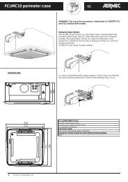
OMNIA <strong>UL</strong> S FANCOIL<br />
The OMNIA <strong>UL</strong> S fan<strong>coil</strong> combines advanced technological<br />
and operational characteristics that make it the ideal<br />
unit for air conditioning any room.<br />
Treated air is immediately delivered to the entire room;<br />
the OMNIA <strong>UL</strong> S produces warm air when fitted to a heating<br />
system with boiler or heat pump, but can also be used<br />
during the summer season as an air-conditioning unit (if the<br />
main system is also equipped with a water chiller).<br />
The filter is easy to remove and is made of materials that<br />
can be regenerated. It can be cleaned by washing. When<br />
the fan<strong>coil</strong> is switched off the fins close, thereby preventing<br />
dust and foreign matter from entering the unit.<br />
The removable drip tray and fan volute ensure thorough<br />
cleaning of the unit (by personnel with the necessary technical<br />
skills), essential for installations in venues subject to<br />
crowding or in those with special hygiene requirements.<br />
The new centrifugal fan assembly is so quiet that during<br />
standard operation it's virtually impossible to hear when the<br />
OMNIA <strong>UL</strong> S starts up.<br />
The OMNIA <strong>UL</strong> S fan<strong>coil</strong> was designed for ceiling installations<br />
and in places where remote control is necessary, for<br />
this reason it does not have a control panel and must be<br />
combined with an optional control panel with thermostat or<br />
commutator.<br />
The use of electronic control panels eliminates the<br />
annoying noises typical of mechanical thermostats.<br />
It is easy to install and the water connections can be<br />
reversed during installation.<br />
Full compliance with safety regulations.<br />
Routine maintenance is limited to periodic cleaning of the<br />
air filter.<br />
USE (OMNIA <strong>UL</strong> S)<br />
CONTROLS:<br />
Ventilation can only take place with the fins open.<br />
These must be opened <strong>manual</strong>ly.<br />
When the fins are closed the ventilation unit switches off.<br />
Consult the <strong>manual</strong> supplied with the remote control accessory.<br />
CHARACTERISTICS OF OPERATION<br />
OMNIA <strong>UL</strong> S fan<strong>coil</strong>s are supplied with on-board controls,<br />
and must be coupled with a compatible control panel<br />
Ventilation<br />
There are three ventilation speeds.<br />
Ventilation is permitted with the fins open only.<br />
PACKAGING<br />
The fan<strong>coil</strong>s are delivered in standard packing comprising<br />
protective shells and cardboard.<br />
7<br />
INSTALLATION<br />
IMPORTANT: check that the power supply is disconnected<br />
before performing operations on the unit.<br />
CAUTION: wiring connections installation of the fan<strong>coil</strong><br />
and relevant accessories should be performed by a technician<br />
who has the necessary technical and professional<br />
expertise to install, modify, extend and maintain plants and<br />
who is able to check the plants for the purposes of safety<br />
and correct operation.<br />
Install the fan<strong>coil</strong> in a position that will facilitate routine (filter<br />
cleaning) and special maintenance, and easy access to the air<br />
breather valve on the side of the unit (connections side).<br />
Note that certain operating conditions could lead to the formation<br />
of condensate on the unit housing with subsequent<br />
dripping, or faults to the water circuit or condensate drainage<br />
could cause liquids to overflow. For these reasons, avoid<br />
installing the unit on surfaces damageable by moisture.<br />
Make sure that the unit is installed in a site where the<br />
ambient temperature is inside the minimum and maximum<br />
limits 0 - 45°C (
GB<br />
CONNECTING CABLES<br />
Use H05V-K or N07V-K cables with insulation 300/500 V<br />
in conduit or raceway. All cables exterior to the fan<strong>coil</strong><br />
must be protected in this way.<br />
Only use power cables with a minimum cross section of<br />
1.5mm 2<br />
Position cable lengths not protected by the conduit or<br />
raceway in such a way as to ensure that they are not subject<br />
to stress, twisting or external agents.<br />
When making connections, always refer to the wiring diagrams<br />
supplied with the unit and shown in this document.<br />
To protect fan <strong>coil</strong>s against short circuits, always fit the<br />
power cable to the units with 2A 250V (IG) thermomagnetic<br />
all-pole switches with a minimum contact gap of<br />
3 mm.<br />
Each control panel controls a single fan<strong>coil</strong>.<br />
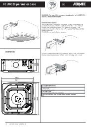
COIL ROTATION<br />
If <strong>coil</strong> rotation is required when making water connections,<br />
remove the unit housing then proceed as follows:<br />
- disconnect wires from the terminal block;<br />
- remove the screws securing the drip tray, then lift it out;<br />
- remove the screws securing the <strong>coil</strong>, then lift it out;<br />
8<br />
- remove the push-outs on the right side;<br />
- rotate the <strong>coil</strong>, then secure it in place with the screws previously<br />
removed;<br />
- refit the drip tray then secure it with the screws; fit the plastic<br />
plugs (supplied) in the holes left vacant by the water<br />
line connections.<br />
(All trays are prearranged for condensate drainage on either<br />
side.<br />
Before connecting up the condensate drain, use a tool to<br />
open the diaphragm in the tray (where fitted) on the water<br />
connection side. Seal the unused drain outlet using the<br />
plug provided.<br />
- Remove the electrical connections from the right hand<br />
side. Remove the push-out and move the cable sheath from<br />
the right to the left.<br />
- Move the motor cable to the left hand side, passing it<br />
through the protective sheath.<br />
- Move the terminal board and the earthing pin to the left<br />
hand side.<br />
- Restore the motor cable electrical connections.<br />
- Disconnect the microswitch.<br />
- Remove the reinforcing stay.<br />
- Pass the wire for the microswitch through the opening on<br />
the opposite side.<br />
- Secure the reinforcing stay.<br />
L<br />
N
IMPORTANT MAINTENANCE INFORMATION<br />
The fan<strong>coil</strong> is connected to the power supply and a water circuit. Operations performed by persons without the required<br />
technical skills can lead to personal injury to the operator or damage to the unit and surrounding objects.<br />
POWER THE FANCOIL WITH SINGLE-PHASE 230 V ONLY<br />
Use of other power supplies could cause permanent damage to the fan<strong>coil</strong>.<br />
NEVER USE THE FANCOIL FOR APPLICATIONS FOR WHICH IT WAS NOT DESIGNED<br />
Do not use the fan<strong>coil</strong> in husbandry applications (e.g. incubation).<br />
AIR THE ROOM<br />
Periodically air the room in which the fan<strong>coil</strong> has been installed; this is particularly important if the room is occupied by<br />
many people, or if gas appliances or sources of odours are present.<br />
CORRECTLY ADJUST THE TEMPERATURE<br />
Room temperature should be regulated to ensure maximum comfort to persons present, particularly in the case of the<br />
elderly, infants and invalids. Prevent temperature fluctuations between indoors and outdoors greater than 7 °C during summer.<br />
Note that very low temperatures during summer will lead to greater electricity consumption.<br />
ORIENT AIR FLOW CORRECTLY<br />
Air delivered by the fan<strong>coil</strong> should not be oriented directly at people; even if air temperature is greater than room temperature,<br />
it can cause a cold sensation and consequently discomfort.<br />
DO NOT USE HOT WATER<br />
When cleaning the indoor unit, use rags or soft sponges soaked in warm water (no higher than 40°C).<br />
Do not use chemical products or solvents to clean any part of the fan<strong>coil</strong>.<br />
Do not splash water on interior or exterior surfaces of the fan<strong>coil</strong>; danger of short circuit.<br />
PERIODICALLY CLEAN THE FILTER<br />
Frequent cleaning of the filter will ensure more efficient unit operation.<br />
Check whether the filter requires cleaning; if it is particularly dirty, clean it more often.<br />
Clean the filter frequently. Use a vacuum cleaner to remove built up dust. Avoid water or detergents if possible since they<br />
greatly accelerate loss of the filter's electrostatic charge.<br />
After cleaning and drying the filter, fit it on the fan<strong>coil</strong> by following the removal procedure in reverse order.<br />
SPECIAL CLEANING<br />
The removable drip tray and fan volute ensure thorough cleaning of the unit (by specifically trained personnel), essential for<br />
installations in venues subject to crowding or in those with special hygiene requirements.<br />
DURING UNIT OPERATION<br />
Always leave the filter on the fan<strong>coil</strong> during operation (otherwise dust in the air could soil the surface of the <strong>coil</strong>).<br />
IT IS NORMAL<br />
During cooling, water vapour may be present in the air delivery.<br />
During heating operation a light rustling sound may be perceived near the fan<strong>coil</strong>.<br />
Sometimes the fan<strong>coil</strong> can give off unpleasant odours due to the accumulation of substances present in the room: air the<br />
room and clean the filter more often.<br />
OPERATING LIMITS<br />
Maximum water inlet temperature 80 °C<br />
Maximum working pressure 8 bar<br />
Minimum average water temperature<br />
To prevent the formation of condensation on the exterior of the unit while the fan is operating, the average water temperature<br />
should not drop beneath the limits shown in the table below, determined by the ambient conditions. These limits refer to<br />
unit operation with fan at minimum speed. Note that condensation may form on the exterior of the unit if cold water circulates<br />
through the <strong>coil</strong> while the fan is off for prolonged periods of time, so it is advisable to fit the additional three-way<br />
valve.<br />
MINIMUM AVERAGE WATER TEMPERATURE<br />
Dry bulb temperature °C<br />
21 23 25 27 29 31<br />
15 3 3 3 3 3 3<br />
17 3 3 3 3 3 3<br />
Wet bulb temperature °C 19 3 3 3 3 3 3<br />
21 6 5 4 3 3 3<br />
23 - 8 7 6 5 5<br />
9<br />
GB
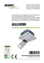
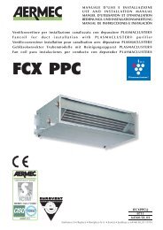
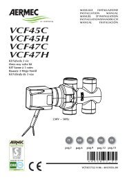
DATI DIMENSIONALI DIMENSIONS DIMENSIONS ABMESSUNGEN [mm]<br />
16<br />
Peso ventilconvettore senza zoccoli Weight of fan <strong>coil</strong> without feet<br />
Poids ventilo-convecteur sans pieds Gewicht Gebläsekonvektor ohne Sockel<br />
OUT<br />
IN<br />
38<br />
149<br />
125<br />
93<br />
207<br />
242<br />
80<br />
426<br />
465<br />
Attacchi batteria (femmina) Coil connection (female)<br />
Raccords batterie (femelle) Anschlüsse des Warmetäuschers (Innengewinde)<br />
Mod. <strong>Omnia</strong> <strong>UL</strong> 11 <strong>Omnia</strong> <strong>UL</strong> 16 <strong>Omnia</strong> <strong>UL</strong> 26 <strong>Omnia</strong> <strong>UL</strong> 36<br />
3 R 1/2” 1/2” 1/2” 1/2”<br />
ZU<br />
50mm<br />
100 mm<br />
50 mm<br />
Mod <strong>UL</strong> 11 <strong>UL</strong> 16 <strong>UL</strong> 26 <strong>UL</strong> 36<br />
Larghezza Width Largeur Breite A [mm] 640 750 980 1200<br />
Altezza Height Hauter Höhe H [mm] 606 606 606 606<br />
Profondità Depth Profondeur Tiefe L [mm] 173 173 173 173<br />
Altezza zoccoli Feet height Hauter pieds Höhe Sockel Z [mm] 94 94 94 94<br />
Peso Weight Poids net Nettogewicht [kg] 12,5 13,5 16,5 19,5
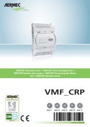
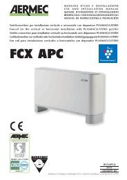
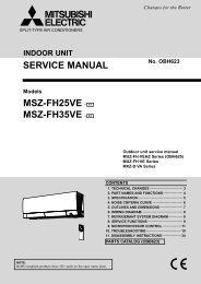
DATI DIMENSIONALI DIMENSIONS DIMENSIONS ABMESSUNGEN [mm]<br />
10<br />
10<br />
6,5<br />
14,5<br />
6,5<br />
544<br />
264<br />
97<br />
31<br />
120<br />
120<br />
r49<br />
5<br />
72 29<br />
5<br />
5<br />
72<br />
26<br />
64<br />
65 54<br />
A<br />
B<br />
C<br />
= =<br />
=<br />
1 Testata con alette orientabili Went with adjustable slats Tête à ailettes orientables Oberer Teil mit verstellbaren Lamellen<br />
2 Mobile di copertura Cabinet Meuble de couverture Gehäuse<br />
3 Struttura portante Bearing structure Structure portante Trägerstruktur<br />
4 Zoccolo ZU Feet ZU Pieds ZU Sockel ZU<br />
5 Spazio per i collegamenti Free space available for connection Espace puor branchements Raum für die Anschlüsse<br />
E<br />
D<br />
³80<br />
145 196<br />
=<br />
C<br />
B<br />
A<br />
=<br />
D<br />
3<br />
=<br />
80<br />
1<br />
5<br />
5<br />
4<br />
5<br />
2<br />
93<br />
106<br />
421<br />
Mod. <strong>UL</strong> 11 <strong>UL</strong> 16 <strong>UL</strong> 26 <strong>UL</strong> 36<br />
A [mm] 640 750 980 1200<br />
B [mm] 384 494 725 945<br />
C [mm] 360,5 470,5 701,5 921,5<br />
D [mm] 288 398 629 849<br />
E [mm] 394 504 735 955<br />
17
SCHEMI ELETTRICI WIRING DIAGRAMS SCHEMAS ELECTRIQUES SCHALTPLÄNE<br />
LEGENDA READING KEY LEGENDE LEGENDE<br />
IG = Interruttore generale Main switch<br />
Interupteur général Hauptschalter<br />
M = Morsettiera Terminal board<br />
Boitier Klemmleiste<br />
MS = Microinterruttore Microswitch<br />
Microinterrupteur Mikroschalter<br />
MV = Motore ventilatore <strong>Fan</strong> motor<br />
Moteur ventilateur Ventilatormotor<br />
PE = Collegamento di terra Earth connection<br />
Mise à terre Erdanschluss<br />
SA = Sonda ambiente Room sensor<br />
Sonde ambiante Raumtemperaturfuhler<br />
SC = Scheda di controllo Electronic control board<br />
Platine de contrôle Steuerschaltkreis<br />
SW = Sonda minima temperatura acqua<br />
Water low temperature sensor<br />
Sonde eau<br />
Fühler Wassertemperatur<br />
OMNIA <strong>UL</strong>-S<br />
18<br />
MS<br />
M 1 2 3 4 5 6 7 8 9 10<br />
Sez. 1,5 mm 2<br />
5<br />
5<br />
VCH = Valvola solenoide Solenoid valve<br />
Vanne solenoide Magnetventil<br />
= Componenti forniti optional Optional components<br />
Composants en option Optionsteile<br />
= Collegamenti da eseguire in loco<br />
On-site wiring<br />
Raccordements à effectuer in situ<br />
Vor Ort auszuführende Anschlüsse<br />
AR = Arancio Orange Orange Orange<br />
BI = Bianco White Blance Weiss<br />
BL = Blu Blue Bleu Blau<br />
GR = Grigio Grey Gris Gray<br />
GV = Giallo-Verde Yellow-Green<br />
Jaune-Vert Gelb-Grün<br />
MA = Marrone Brown Marron Braun<br />
NE = Nero Black Noir Schwarz<br />
RO = Rosso Red Rouge Rot<br />
BL NE MA RO<br />
1 2 3 4<br />
1 2 3 4<br />
MAX<br />
MED<br />
MIN<br />
BL NE MA<br />
M<br />
RO<br />
1<br />
MV<br />
6<br />
6<br />
IG<br />
230V ~ 50Hz<br />
Gli schemi elettrici sono soggetti ad aggiornamento; è opportuno fare riferimento allo schema elettrico allegato all' apparecchio.<br />
Wiring diagrams may change for updating. It is therefore necessary to refer always to the wiring diagram inside the units.<br />
Les schémas électriques peuvent être modifies en conséquence des mises à jour. Il faut toujours se référer aux schémas électriques dans les appareils.<br />
Die Schaltschemas können geändert werden; es empfiehlt sich immer auf das mit dem Gerät verpackte El. Schaltschema zu beziehen.<br />
PE<br />
PE<br />
N<br />
L
SCHEMI ELETTRICI WIRING DIAGRAMS SCHEMAS ELECTRIQUES SCHALTPLÄNE<br />
MS<br />
M<br />
1 2 3 4 5 6 7 8 9 10<br />
<strong>Omnia</strong><br />
BL NE MA RO<br />
Sez. 1,5 mm 2<br />
MS<br />
5 1 2 3 4 6<br />
5 1 2 3 4 6<br />
MAX<br />
MED<br />
M<br />
1<br />
MIN<br />
BL NE MA RO<br />
M<br />
1 2 3 4 5 6 7 8 9 10<br />
<strong>Omnia</strong><br />
BL NE MA RO<br />
VCH<br />
Sez. 1,5 mm 2<br />
MV<br />
5 1 2 3 4 6<br />
5 1 2 3 4 6<br />
MAX<br />
MED<br />
M<br />
1<br />
MIN<br />
BL NE MA RO<br />
MV<br />
M<br />
Gli schemi elettrici sono soggetti ad aggiornamento; è opportuno fare riferimento allo schema elettrico allegato all' apparecchio.<br />
Wiring diagrams may change for updating. It is therefore necessary to refer always to the wiring diagram inside the units.<br />
Les schémas électriques peuvent être modifies en conséquence des mises à jour. Il faut toujours se référer aux schémas électriques dans les appareils.<br />
Die Schaltschemas können geändert werden; es empfiehlt sich immer auf das mit dem Gerät verpackte El. Schaltschema zu beziehen.<br />
PX2<br />
1<br />
2<br />
3<br />
4<br />
5<br />
6<br />
IG<br />
230V ~ 50Hz<br />
CE<br />
IG<br />
230V ~ 50Hz<br />
N<br />
L<br />
PE<br />
N<br />
L<br />
MAX 15m<br />
MS*<br />
MAX 100m<br />
SW<br />
MAX 15<br />
PE<br />
PXAE<br />
M1<br />
N<br />
L<br />
V1<br />
V2<br />
V3<br />
Y1<br />
Y2<br />
CE<br />
CE<br />
MS<br />
MS<br />
SW<br />
SW<br />
EXT<br />
JP1<br />
INT<br />
-<br />
SA (INT)<br />
+<br />
19
SCHEMI ELETTRICI WIRING DIAGRAMS SCHEMAS ELECTRIQUES SCHALTPLÄNE<br />
Gli schemi elettrici sono soggetti ad aggiornamento; è opportuno fare riferimento allo schema elettrico allegato all' apparecchio.<br />
Wiring diagrams may change for updating. It is therefore necessary to refer always to the wiring diagram inside the units.<br />
Les schémas électriques peuvent être modifies en conséquence des mises à jour. Il faut toujours se référer aux schémas électriques dans les appareils.<br />
Die Schaltschemas können geändert werden; es empfiehlt sich immer auf das mit dem Gerät verpackte El. Schaltschema zu beziehen.<br />
20<br />
MS<br />
MS<br />
MS<br />
M 1 2 3 4 5 6 7 8 9 10<br />
<strong>Omnia</strong><br />
BL NE MA RO<br />
PE<br />
IG<br />
L<br />
MS<br />
M 1 2 3 4 5 6 7 8 9 10<br />
<strong>Omnia</strong><br />
BL NE MA RO<br />
VCH<br />
PE<br />
IG<br />
L<br />
N<br />
5<br />
5<br />
N<br />
230V ~ 50Hz<br />
5<br />
5<br />
1 2 3 4<br />
1 2 3 4<br />
BL NE MA RO<br />
Sez. 1,5 mm 2<br />
MAX<br />
1 2 3 4<br />
1 2 3 4<br />
Sez. 1,5 mm 2<br />
230V ~ 50Hz<br />
MED<br />
M<br />
1<br />
MAX<br />
MIN<br />
MV<br />
MED<br />
BL NE MA RO<br />
M<br />
1<br />
MIN<br />
MV<br />
6<br />
6<br />
6<br />
6<br />
L1~<br />
L2 - N<br />
COOL<br />
HEAT<br />
1234N<br />
LOW<br />
MED<br />
HIGH<br />
WMT05<br />
WMT10
SCHEMI ELETTRICI WIRING DIAGRAMS SCHEMAS ELECTRIQUES SCHALTPLÄNE<br />
MS<br />
MS<br />
MS<br />
M 1 2 3 4 5 6 7 8 9 10<br />
<strong>Omnia</strong><br />
BL NE MA RO<br />
5 1 2 3 4 6<br />
5 1 2 3 4 6<br />
VCH<br />
PE<br />
IG<br />
MS<br />
M 1 2 3 4 5 6 7 8 9 10<br />
<strong>Omnia</strong><br />
BL NE MA RO<br />
5 1 2 3 4 6<br />
5 1 2 3 4 6<br />
VCH<br />
PE<br />
IG<br />
L<br />
L<br />
N<br />
Sez. 1,5 mm 2<br />
230V ~ 50Hz<br />
N<br />
Sez. 1,5 mm 2<br />
230V ~ 50Hz<br />
MAX<br />
MAX<br />
MED<br />
BL NE MA RO<br />
M<br />
1<br />
MED<br />
BL NE MA RO<br />
M<br />
1<br />
MIN<br />
MV<br />
MIN<br />
MV<br />
M<br />
M<br />
EXT. SENSOR<br />
C650 FS - 1C - 1H<br />
EXT. SENSOR<br />
C650 FS - 1C - 1H<br />
Gli schemi elettrici sono soggetti ad aggiornamento; è opportuno fare riferimento allo schema elettrico allegato all' apparecchio.<br />
Wiring diagrams may change for updating. It is therefore necessary to refer always to the wiring diagram inside the units.<br />
Les schémas électriques peuvent être modifies en conséquence des mises à jour. Il faut toujours se référer aux schémas électriques dans les appareils.<br />
Die Schaltschemas können geändert werden; es empfiehlt sich immer auf das mit dem Gerät verpackte El. Schaltschema zu beziehen.<br />
L1~<br />
L1~<br />
L2 - N<br />
L2 - 0<br />
COOL<br />
COOL<br />
HEAT<br />
HEAT<br />
LOW<br />
LOW<br />
MED<br />
MED<br />
HIGH<br />
ON OFF<br />
HIGH<br />
N/C<br />
FMT10<br />
WARMER<br />
COOLER<br />
FMT20<br />
21
SCHEMI ELETTRICI WIRING DIAGRAMS SCHEMAS ELECTRIQUES SCHALTPLÄNE<br />
Gli schemi elettrici sono soggetti ad aggiornamento; è opportuno fare riferimento allo schema elettrico allegato all' apparecchio.<br />
Wiring diagrams may change for updating. It is therefore necessary to refer always to the wiring diagram inside the units.<br />
Les schémas électriques peuvent être modifies en conséquence des mises à jour. Il faut toujours se référer aux schémas électriques dans les appareils.<br />
Die Schaltschemas können geändert werden; es empfiehlt sich immer auf das mit dem Gerät verpackte El. Schaltschema zu beziehen.<br />
22<br />
MS<br />
AL<br />
M2<br />
12Vdc GND<br />
230 0<br />
M1<br />
M<br />
1<br />
2<br />
3<br />
4 5<br />
IG<br />
L N<br />
6 7<br />
8<br />
MAX<br />
9<br />
MED<br />
M<br />
1<br />
MV<br />
10<br />
MIN<br />
BL NE MA RO<br />
230V ~ 50Hz<br />
PE<br />
1 2 3 4<br />
ML<br />
NE<br />
BI<br />
BL<br />
GI<br />
RO<br />
5<br />
EX<br />
SW<br />
SC<br />
V1<br />
V2<br />
V3<br />
L<br />
N<br />
1<br />
2<br />
3<br />
4<br />
5<br />
EX<br />
EX<br />
12V<br />
GND<br />
SA<br />
SA<br />
SW<br />
SW<br />
M2<br />
M1<br />
CN1<br />
M3<br />
M4<br />
SA<br />
-<br />
+
SCHEMI ELETTRICI WIRING DIAGRAMS SCHEMAS ELECTRIQUES SCHALTPLÄNE<br />
PXAE<br />
F 1A<br />
M1<br />
N<br />
L<br />
V3 V2 V1 N N PH L<br />
INPUT<br />
SIT5<br />
OUTPUT<br />
V1 V2 V3<br />
Y1<br />
Y2<br />
+<br />
-<br />
V1<br />
Y1<br />
V3<br />
V2<br />
Y2<br />
CE<br />
CE<br />
MS<br />
MS<br />
F<br />
2A<br />
Y1<br />
Y2<br />
V1 V2<br />
OUTPUT<br />
V3<br />
SIT3/1<br />
V3 V2 V1 N L<br />
NINPUT<br />
PH<br />
F<br />
2A<br />
V1 V2<br />
OUTPUT<br />
V3<br />
SIT3/2<br />
V3 V2 V1 N L<br />
NINPUT<br />
PH<br />
F<br />
2A<br />
V1 V2<br />
OUTPUT<br />
V3<br />
SIT3/10<br />
V3 V2 V1 N L<br />
NINPUT<br />
PH<br />
Gli schemi elettrici sono soggetti ad aggiornamento; è opportuno fare riferimento allo schema elettrico allegato all' apparecchio.<br />
Wiring diagrams may change for updating. It is therefore necessary to refer always to the wiring diagram inside the units.<br />
Les schémas électriques peuvent être modifies en conséquence des mises à jour. Il faut toujours se référer aux schémas électriques dans les appareils.<br />
Die Schaltschemas können geändert werden; es empfiehlt sich immer auf das mit dem Gerät verpackte El. Schaltschema zu beziehen.<br />
L = 15m MAX<br />
MS<br />
MS<br />
MS<br />
SW<br />
SW<br />
EXT<br />
M 1 2 3 4 5<br />
M 1 2 3 4 5 6 7 8 9 10<br />
M 1 2 3 4 5 6 7 8 9 10<br />
SA (INT)<br />
6<br />
JP1<br />
INT<br />
6<br />
6<br />
7 8 9 10<br />
BL NE MA RO<br />
1 2 3 4<br />
1 2 3 4<br />
5<br />
5<br />
6<br />
6<br />
BL NE MA RO<br />
1 2 3 4<br />
1 2 3 4<br />
5<br />
5<br />
6<br />
6<br />
BL NE MA RO<br />
1 2 3 4<br />
1 2 3 4<br />
5<br />
5<br />
MIN<br />
MED<br />
MAX<br />
MIN<br />
MED<br />
MAX<br />
MIN<br />
MED<br />
MAX<br />
VCH<br />
VCH<br />
VCH<br />
<strong>Omnia</strong>/1<br />
BL NE MA RO<br />
M<br />
1<br />
MV<br />
<strong>Omnia</strong>/2<br />
BL NE MA RO<br />
M<br />
1<br />
MV<br />
<strong>Omnia</strong>/N<br />
BL NE MA RO<br />
M<br />
1<br />
MV<br />
PE<br />
IG<br />
4A L N<br />
230V ~ 50Hz<br />
23
TRASPORTO CARRIAGE TRANSPORT TRANSPORT<br />
24<br />
NON bagnare Do NOT wet<br />
CRAINT l’humidité Vor Nässe schützen<br />
Sovrapponibilità: controllare sull’imballo la posizione della freccia per<br />
conoscere il numero di macchine impilabili<br />
Stacking: control the packing for the arrow position to know the number<br />
of machines that can be stacked<br />
Empilement: vérifier sur l’emballage la position de la flèche pour connaître<br />
le nombre d’appareils pouvant être empilés<br />
Stapelung: Anhand der Position des Pfeiles an der Verpackung kontrollieren,<br />
wieviele Geräte stapelbar sind<br />
NON trasportare la macchina da soli se il suo peso supera i 35 Kg.<br />
DO NOT handle the machine alone if its weight is over 35 Kg.<br />
NE PAS transporter tout seul l’appareil si son poids dépasse 35 Kg.<br />
Das Gerät NICHT alleine tragen, wenn sein Gewicht 35 Kg überschreitet.<br />
NON calpestare Do NOT trample<br />
NE PAS marcher sur cet emballage Nicht betreten<br />
6<br />
5<br />
4<br />
3<br />
2<br />
1<br />
NON lasciare gli imballi sciolti durante il trasporto<br />
Do NOT leave loose packages during transport<br />
ATTACHER les emballages pendant le transport<br />
Die Verpackungen nicht ungesichert transportieren<br />
35Kg<br />
SIMBOLI DI SICUREZZA SAFETY SYMBOL SIMBOLES DE SECURITE SICHERHEITSSYMBOLE<br />
Pericolo: Pericolo: Pericolo!!!<br />
Tensione Organi in movimento<br />
Danger: Danger: Danger!!!<br />
Power supply Movings parts<br />
Danger: Danger: Danger!!!<br />
Tension Organes en mouvement<br />
Gefahr ! Gefahr ! Gefahr!!!<br />
Spannung Rotierende Teile
PROBLEMA PROBLEM<br />
PROBLEME PROBLEM<br />
Poca aria in uscita<br />
Feeble air discharge<br />
Il y a peu d’air en sortie<br />
Schwacher Luftstrom am A<br />
ustritt<br />
Non fa caldo<br />
It does not heat<br />
Pas de chaleur<br />
Keine Heizung<br />
Non fa freddo<br />
It does not cool<br />
Pas de froid<br />
Keine Kühlung<br />
Il ventilatore non gira<br />
The fan does not turn<br />
Le ventilateur ne tourne pas<br />
Ventilator Arbeitet nicht<br />
Fenomeni di condensazione<br />
sulla struttura esterna<br />
dell’apparecchio.<br />
Condensation on the unit<br />
cabinet.<br />
Phénomènes de condensation<br />
sur la structure exterieure<br />
de l’appareil.<br />
Kondenswasserbildung am<br />
Gerät.<br />
PROBABILE CAUSA PROBABLE CAUSE<br />
CAUSE PROBABLE MÖGLICHE URSACHE<br />
Errata impostazione della velocità sul pannello comandi<br />
Wrong speed setting on the control panel<br />
Mauvaise préselection de la vitesse sur le panneau de commandes<br />
Falsche Geschwindigkeitseinstellung am Bedienpaneel<br />
Filtro intasato<br />
Blocked filter<br />
Filtre encrassé<br />
Filter verstopft<br />
Ostruzione del flusso d’aria (entrata e/o uscita)<br />
Obstruction of the air flow (inlet and/or outlet)<br />
Obstruction du flux d’air (entrée/sortie)<br />
Luftstrom behindert (Eintritt bzw. Austritt)<br />
Mancanza di acqua calda<br />
Poor hot water supply<br />
Il n’y a pas d’eau chaude<br />
Kein Warmwasser<br />
Impostazione errata del pannello comandi<br />
Wrong setting on control panel<br />
Mauvaise présélection sur le panneau de commandes<br />
Falsche Einstellung am Bedienpaneel<br />
Mancanza di acqua fredda<br />
Poor chilled water supply<br />
Il n’y a pas d’eau froide<br />
Kein Kaltwasser<br />
Impostazione errata del pannello comandi<br />
Wrong setting on control panel<br />
Mauvaise présélection sur le panneau de commandes<br />
Falsche Einstellung am Bedienpaneel<br />
Mancanza di corrente<br />
No current<br />
l n’y a pas de courant<br />
Kein Strom<br />
L’acqua non ha raggiunto la temperatura d’esercizio.<br />
The water has not reached operating temperature.<br />
L'eau n'a pas atteint la température de service.<br />
Das Wasser hat die Betriebstemperatur nicht erreicht.<br />
Sono state raggiunte le condizioni limite di temperatura e<br />
umidità descritte in “MINIMA TEMPERATURA MEDIA<br />
DELL’ACQUA”.<br />
The limit conditions of temperature and humidity indicated in<br />
“MINIMUM AVERAGE WATER TEMPERATURE” have been<br />
reached.<br />
On a atteint les conditions limite de température et d’humidité<br />
indiquées dans “TEMPERATURE MINIMALE MOYENNE<br />
DE L'EAU”.<br />
Erreichen der maximalen Temperatur- und Feuchtigkeitswerte<br />
(siehe Abschnitt “DURCHSCHNITTLICHE MINDEST -<br />
WASSERTEMPERATUR”).<br />
Per anomalie non contemplate, interpellare tempestivamente il Servizio Assistenza.<br />
For anomalies don’t hesitate, contact the aftersales service immediately.<br />
Pour toute anomalie non répertoriée, consulter le service après-vente.<br />
Sich bei hier nicht aufgeführten Störungen umgehend an den Kundendienst wenden.<br />
SOLUZIONE REMEDY<br />
SOLUTION ABHILFE<br />
Scegliere la velocità corretta sul pannello<br />
comandi<br />
Select the speed on the control panel<br />
Choisir la vitesse sur la panneau de commandes<br />
Die Geschwindigkeit am Bedienpaneel wählen<br />
Pulire il filtro<br />
Clean the filter<br />
Nettoyer le filtre<br />
Filter reinigen<br />
Rimuovere l’ostruzione<br />
Remove the obstruction<br />
Enlever l’objet faisant obstruction<br />
Verstopfung beseitigen<br />
Controllare la caldaia<br />
Control the boiler<br />
Verifier la chaudière<br />
Kaltwasserseitigen Wärmeaustauscher kontrollieren<br />
Impostare il pannello comandi<br />
See control panel settings<br />
Présélectionner au panneau de commandes<br />
Richtige Einstellung am Bedienpaneel vornehmen<br />
Controllare il refrigeratore<br />
Control the chiller<br />
Vérifier le réfrigerateur<br />
Kaltwasserseitigen Wärmeaustauscher kontrollieren<br />
Impostare il pannello comandi<br />
See control panel settings<br />
Présélectionner au panneau de commandes<br />
Richtige Einstellung am Bedienpaneel vornehmen<br />
Controllare la presenza di tensione elettrica<br />
Control the power supply<br />
Contrôler l’alimentation électrique<br />
Kontrollieren, ob Spannung anliegt<br />
Controllare la caldaia o il refrigeratore.<br />
Controllare il settaggio del termostato<br />
Please check up the boiler or the chiller.<br />
Check up the thermostat settings.<br />
Contrôler la chaudière ou le refroidisseur.<br />
Contrôler le réglage du thermostat.<br />
Das Heiz- oder Kühlaggregat überprüfen.<br />
Die Einstellungen des Temperaturreglers<br />
überprüfen.<br />
Innalzare la temperatura dell’acqua oltre i<br />
limiti minimi descritti in “MINIMA TEMPERA-<br />
TURA MEDIA DELL’ACQUA”.<br />
Increase the water temperature beyond the<br />
minimum limits indicated in “MINIMUM<br />
AVERAGE WATER TEMPERATURE”.<br />
Elever la température de l’eau audelà des<br />
limites minimales indiquées dans “TEMPERA-<br />
TURE MINIMALE MOYENNE DE L'EAU”.<br />
Wassertemperatur über die um Abschnitt<br />
“DURCHSCHNITTLICHE MINDEST -<br />
WASSERTEMPERATUR” angegebenen min.<br />
Werte erhöhen.<br />
25
GARANZIA DI 3 ANNI<br />
La garanzia è valida solo se l’apparecchio è venduto ed installato sul territorio italiano. Il periodo decorre dalla data d’acquisto comprovata da<br />
un documento che abbia validità fiscale (fattura o ricevuta) e che riporti la sigla commerciale dell’apparecchio. Il documento dovrà essere esibito,<br />
al momento dell’intervento, al tecnico del Servizio Assistenza <strong>Aermec</strong> di zona.<br />
Il diritto alla garanzia decade in caso di:<br />
– interventi di riparazione effettuati sull’apparecchiatura da tecnici non autorizzati;<br />
– guasti conseguenti ad azioni volontarie o accidentali che non derivino da difetti originari dei materiali di fabbricazione.<br />
AERMEC Spa effettuerà la riparazione o la sostituzione gratuita, a sua scelta, delle parti di apparecchiatura che dovessero presentare difetti dei<br />
materiali o di fabbricazione tali da impedirne il normale funzionamento. Gli eventuali interventi di riparazione o sostituzione di parti<br />
dell’apparecchio, non modificano la data di decorrenza e la durata del periodo di garanzia. Le parti difettose sostituite resteranno di proprietà<br />
della AERMEC Spa.<br />
Non è prevista in alcun caso la sostituzione dell’apparecchio. La garanzia non copre le parti dell’apparecchio che risultassero difettose a<br />
causa del mancato rispetto delle istruzioni d’uso, di un’errata installazione o manutenzione, di danneggiamenti dovuti al trasporto, di difetti<br />
dell’impianto (es: scarichi di condensa non efficienti).Non sono coperte, infine, le normali operazioni di manutenzione periodica (es: la pulizia<br />
dei filtri d’aria) e la sostituzione delle parti di normale consumo (es: i filtri d’aria).<br />
Le agenzie di Vendita <strong>Aermec</strong> ed i Servizi di Assistenza Tecnica <strong>Aermec</strong> della vostra provincia sono negli Elenchi telefonici dei capoluoghi<br />
di provincia - vedi “<strong>Aermec</strong>” - e nelle Pagine Gialle alla voce “Condizionatori d’aria - Commercio”.<br />
<strong>Aermec</strong> partecipa al Programma di<br />
Certificazione EUROVENT.<br />
I prodotti interessati figurano nella Guida<br />
EUROVENT dei Prodotti Certificati.<br />
I dati tecnici riportati nella presente documentazione non sono impegnativi.<br />
AERMEC S.p.A. si riserva la facoltà di apportare in qualsiasi momento<br />
tutte le modifiche ritenute necessarie per il miglioramento del prodotto.<br />
Les données mentionnées dans ce manuel ne constituent aucun engagement<br />
de notre part. <strong>Aermec</strong> S.p.A. se réserve le droit de modifier à tous<br />
moments les données considérées nécessaires à l’amelioration du produit.<br />
AERMEC S.p.A.<br />
I-37040 Bevilacqua (VR) - Italia<br />
Via Roma, 44 - Tel. (+39) 0442 633111<br />
Telefax (+39) 0442 93730 - (+39) 0442 93566<br />
www .aermec. com - info @aermec. com<br />
<strong>Aermec</strong> partecipe au Programme de<br />
Certification EUROVENT.<br />
Les produits figurent dans l’Annuaire<br />
EUROVENT des Produits Certifiés.<br />
<strong>Aermec</strong> is partecipating in the EUROVENT<br />
Certification Program.<br />
Products are as listed in the EUROVENT<br />
Directory of Certified Products.<br />
<strong>Aermec</strong> ist am Zertifikations - Programm<br />
EUROVENT beteiligt.<br />
Die entsprechend gekennzeichneten Produkte<br />
sind im EUROVENT - Jahrbuch aufgefürt.<br />
Technical data shown in this booklet are not binding.<br />
<strong>Aermec</strong> S.p.A. shall have the right to introduce at any time whatever<br />
modifications deemed necessary to the improvement of the product.<br />
Im Sinne des technischen Fortsschrittes behält sich <strong>Aermec</strong> S.p.A. vor,<br />
in der Produktion Änderungen und Verbesserungen ohne<br />
Ankündigung durchzuführen.<br />
carta riciclata<br />
recycled paper<br />
papier recyclé<br />
recycled Papier