Fan coil Aermec Omnia UL PC Installation manual
Fan coil Aermec Omnia UL PC Installation manual
Fan coil Aermec Omnia UL PC Installation manual

You also want an ePaper? Increase the reach of your titles
YUMPU automatically turns print PDFs into web optimized ePapers that Google loves.
<strong>Omnia</strong> <strong>UL</strong> 11 <strong>PC</strong><br />
<strong>Omnia</strong> <strong>UL</strong> 16 <strong>PC</strong><br />
<strong>Omnia</strong> <strong>UL</strong> 26 <strong>PC</strong><br />
<strong>Omnia</strong> <strong>UL</strong> 36 <strong>PC</strong><br />
MANUALE D’USO E INSTALLAZIONE<br />
USE AND INSTALLATION MANUAL<br />
MANUEL D’UTILISATION ET D’INSTALLATION<br />
BEDIENUNGS- UND INSTALLATIONSANLEITUNG<br />
MANUAL DE INSTRUCCIONES E INSTALACIÓN<br />
VENTILCONVETTORE PER INSTALLAZIONE UNIVERSALE<br />
CON DEPURATORE PLASMACLUSTER®<br />
FAN COIL FOR UNIVERSAL INSTALLATION<br />
WITH PLASMACLUSTER® PURIFIER<br />
VENTILO-CONVECTEUR POUR INSTALLATION UNIVERSELLE<br />
AVEC DÉPURATEUR PLASMACLUSTER®<br />
GEBLÄSEKONVEKTOR FÜR UNIVERSELLEN EINBAU<br />
MIT REINIGUNGSAPPARAT PLASMACLUSTER®<br />
FAN COIL PARA INSTALACIÓN UNIVERSAL<br />
CON DEPURADOR PLASMACLUSTER®<br />
<strong>Omnia</strong> <strong>UL</strong> <strong>PC</strong><br />
I<strong>UL</strong><strong>PC</strong>LJ 1004 - 6976408_02<br />
Sostituisce il Replace Remplace le n° Ersetzt Sustituye a: 69764.08_01 / 0711
INDICE TABLE OF CONTENTS INDEX INHALTSVERZEICHN ÍNDICE<br />
I<br />
GB<br />
F<br />
D<br />
E<br />
INFORMAZIONI GENERALI 3<br />
Descrizione di <strong>Omnia</strong> <strong>UL</strong> <strong>PC</strong> 6<br />
Utilizzo Visualizzazioni 7<br />
Caratteristiche di funzionamento Imballo Installazione dell’unità 8<br />
Collegamenti elettrici Rotazione batteria 9<br />
Autotest Configurazione Dip 10<br />
Informazioni importanti e manutenzione 11<br />
DATI DIMENSIONALI 36<br />
SCHEMA ELETTRICO 38<br />
SOLUZIONE DEI PROBLEMI 39<br />
SERVIZIO ASSISTENZA TECNICA IN ITALIA 43<br />
GENERAL INFORMATION 3<br />
Description of the <strong>Omnia</strong> <strong>UL</strong> <strong>PC</strong> 12<br />
Use Displays 13<br />
Operating characteristics Packaging Unit installation 14<br />
Electrical connections Battery rotation 15<br />
Autotest Configuration Dip 16<br />
Important information and maintenance 17<br />
DIMENSIONAL DATA 36<br />
WIRING DIAGRAM 38<br />
TROUBLE SHOOTING 43<br />
INFORMATIONS GÉNÉRALES 3<br />
Description d'<strong>Omnia</strong> <strong>UL</strong> <strong>PC</strong> 18<br />
Utilisation Affichages 19<br />
Caractéristiques de fonctionnement Emballage <strong>Installation</strong> de l'unité 20<br />
Raccordements électriques Rotation batterie 21<br />
Autotest Configuration Dip 22<br />
Informations importantes et entretien 23<br />
DONNEES DIMENSIONNELLES 36<br />
SCHEMA ELECTRIQUE 38<br />
SOLUTION DES PROBLEMES 43<br />
ALLGEMEINE INFORMATIONEN 3<br />
Beschreibung für <strong>Omnia</strong> <strong>UL</strong> <strong>PC</strong> 24<br />
Gebrauch Anzeigen 25<br />
Betriebsmerkmale Verpackung <strong>Installation</strong> der Einheit 26<br />
Elektrische Anschlüsse Umdrehen des Wärmetauschers 27<br />
Autotest Konfiguration Dip 28<br />
Wichtige Informationen und Wartung 29<br />
ABMESSUNGEN 36<br />
ELEKTRISCHER SCHALTPLAN 38<br />
PROBLEMLÖSUNG 43<br />
INFORMACIÓN GENERAL 3<br />
Descripción de <strong>Omnia</strong> <strong>UL</strong> <strong>PC</strong> 30<br />
Uso Visualizaciones 31<br />
Propiedades de funcionamiento Embalaje Instalación de la unidad 32<br />
Conexiones eléctricas Giro batería 33<br />
Autotest Configuración Dip 34<br />
Información importante y mantenimiento 35<br />
DIMENSIONES 36<br />
DIAGRAMA ELÉCTRICO 38<br />
SOLUCIÓN DE PROBLEMAS 43
AERMEC S.p.A.<br />
I-37040 Bevilacqua (VR) Italia – Via Roma, 996<br />
Tel. (+39) 0442 633111<br />
Telefax (+39) 0442 93730 – (+39) 0442 93566<br />
www .aermec. com - info @aermec. com<br />
DICHIARAZIONE DI CONFORMITÀ<br />
Noi, fi rmatari della presente, dichiariamo sotto la nostra esclusiva<br />
responsabilità, che il prodotto:<br />
VENTILCONVETTORE<br />
serie <strong>Omnia</strong> <strong>UL</strong> <strong>PC</strong><br />
al quale questa dichiarazione si riferisce è conforme alle seguenti norme<br />
armonizzate:<br />
- CEI EN 60335-2-40<br />
- CEI EN 55014-1<br />
- CEI EN 55014-2<br />
- CEI EN 61000-6-1<br />
- CEI EN 61000-6-2<br />
- CEI EN 61000-6-3<br />
- CEI EN 61000-6-4<br />
soddisfando così i requisiti essenziali delle seguenti direttive:<br />
- Direttiva LVD 2006/95/CE<br />
- Direttiva compatibilità elettromagnetica EMC2004/108/CE<br />
OMNIA <strong>UL</strong> <strong>PC</strong> CON ACCESSORI<br />
E’ fatto divieto di mettere in servizio il prodotto dotato di accessori<br />
non di fornitura <strong>Aermec</strong>.<br />
CERTIFICAT DE CONFORMITÉ<br />
Nous soussignés déclarons sous notre exclusive responsabilité que le<br />
produit:<br />
VENTILO-CONVECTEURS<br />
série <strong>Omnia</strong> <strong>UL</strong> <strong>PC</strong><br />
auquel cette déclaration fait référence, est conforme aux normes<br />
harmonisées suivantes:<br />
- EN 60335-2-40<br />
- EN 55014-1<br />
- EN 55014-2<br />
- CEI EN 61000-6-1<br />
- CEI EN 61000-6-2<br />
- CEI EN 61000-6-3<br />
- CEI EN 61000-6-4<br />
satisfaisant ainsi aux conditions essentielles des directives suivantes:<br />
- Directive LVD 2006/95/CE<br />
- Directive compatibilité électromagnétique EMC2004/108/CE<br />
OMNIA <strong>UL</strong> <strong>PC</strong> PLUS ACCESSOIRES<br />
Il est interdit de faire fonctionner l'appareil avec des accessoires qui<br />
ne sont pas fournis de <strong>Aermec</strong>.<br />
DECLARACIÓN DE CONFORMIDAD<br />
Los que suscriben la presente declaran bajo la propia y exclusiva<br />
responsabilidad que el conjunto en objeto, defi nido como sigue:<br />
FAN COIL<br />
serie <strong>Omnia</strong> <strong>UL</strong> <strong>PC</strong><br />
al que esta declaración se refi ere, está en conformidad a las siguientes<br />
normas armonizadas:<br />
- EN 60335-2-40<br />
- EN 55014-1<br />
- EN 55014-2<br />
- CEI EN 61000-6-1<br />
- CEI EN 61000-6-2<br />
- CEI EN 61000-6-3<br />
- CEI EN 61000-6-4<br />
- EN 61000-6-3<br />
al que esta declaración se refi ere, está en conformidad a las siguientes<br />
normas armonizadas:<br />
- Directiva LVD 2006/95/CE<br />
- Directiva compatibilidad electromagnétic EMC2004/108/CE<br />
OMNIA <strong>UL</strong> <strong>PC</strong> CON ACCESORIOS<br />
Está prohibido poner en marcha el producto con accesorios<br />
no suministrados por <strong>Aermec</strong>.<br />
<strong>Omnia</strong> <strong>UL</strong>_<strong>PC</strong><br />
CONFORMITY DECLARATION<br />
We the undersigned declare, under our own exclusive responsibility,<br />
that the product:<br />
FAN COIL<br />
<strong>Omnia</strong> <strong>UL</strong> <strong>PC</strong> series<br />
to which this declaration refers, complies with the following standardised<br />
regulations:<br />
- EN 60335-2-40<br />
- EN 55014-1<br />
- EN 55014-2<br />
- CEI EN 61000-6-1<br />
- CEI EN 61000-6-2<br />
- CEI EN 61000-6-3<br />
- CEI EN 61000-6-4<br />
thus meeting the essential requisites of the following directives:<br />
- Directive LVD 2006/95/CE<br />
- EMC Electromagnetic Compatibility Directive 2004/108/CE<br />
OMNIA <strong>UL</strong> <strong>PC</strong> WITH ACCESSORIES<br />
It is not allowed to use the unit equipped with accessories not supplied<br />
by <strong>Aermec</strong>.<br />
KONFORMITÄTSERKLÄRUNG<br />
Wir, die hier Unterzeichnenden, erklären auf unsere ausschließlich<br />
Verantwortung, dass das Produkt:<br />
GEBLÄSEKONVEKTOR<br />
der Serie <strong>Omnia</strong> <strong>UL</strong> <strong>PC</strong><br />
auf das sich diese Erklärung bezieht, den folgenden harmonisierten<br />
Normen entspricht:<br />
- EN 60335-2-40<br />
- EN 55014-1<br />
- EN 55014-2<br />
- CEI EN 61000-6-1<br />
- CEI EN 61000-6-2<br />
- CEI EN 61000-6-3<br />
- CEI EN 61000-6-4<br />
womit die grundlegenden Anforderungen folgender Richtlinien erfüllt werden:<br />
- Richtlinie LVD 2006/95/CE<br />
- Richtlinie zur elektromagnetischen Verträglichkeit EMC2004/108/CE<br />
OMNIA <strong>UL</strong> <strong>PC</strong> + ZUBEHÖR<br />
Falls das Gerät mit Zubehörteilen ausgerüstet wird, die nicht von<br />
<strong>Aermec</strong> geliefert werden, ist dessen Inbetriebnahme solange untersagt.<br />
La persona autorizzata a costituire il fascicolo tecnico è: / The person authorized to compile the technical file is: / La personne autorisée<br />
à constituer le dossier technique est: / Die Person berechtigt, die technischen Unterlagen zusammenzustellen: Pierpaolo Cavallo<br />
Bevilacqua, 11/01/2010 La Direzione Commerciale – Sales and Marketing Director<br />
Luigi Zucchi
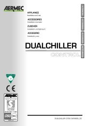
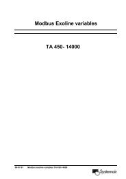
TRASPORTO CARRIAGE TRANSPORT TRANSPORT TRANSPORTE<br />
4<br />
NON bagnare Do NOT wet<br />
CRAINT l’humidité Vor Nässe schützen<br />
NO mojar<br />
Sovrapponibilità: controllare sull’imballo la posizione della freccia per<br />
conoscere il numero di macchine impilabili.<br />
Stacking: control the packing for the arrow position to know the number<br />
of machines that can be stacked.<br />
Empilement: vérifier sur l’emballage la position de la flèche pour connaître<br />
le nombre d’appareils pouvant être empilés.<br />
Stapelung: Anhand der Position des Pfeiles an der Verpackung kontrollieren,<br />
wieviele Geräte stapelbar sind.<br />
Apilamiento: observe en el embalaje la posición de la flecha para saber<br />
cuántos equipos pueden apilarse.<br />
NON trasportare la macchina da soli se il suo peso supera i 35 Kg.<br />
DO NOT handle the machine alone if its weight is over 35 Kg.<br />
NE PAS transporter tout seul l’appareil si son poids dépasse 35 Kg.<br />
Das Gerät NICHT alleine tragen, wenn sein Gewicht 35 Kg überschreitet.<br />
NO maneje los equipos en solitario si pesan más de 35 kg.<br />
SIMBOLI DI SICUREZZA SAFETY SYMBOL SIMBOLES DE SECURITE<br />
SICHERHEITSSYMBOLE SÍMBOLOS DE SEGURIDAD<br />
I<strong>UL</strong><strong>PC</strong>LJ 1002 - 6976408_01<br />
NON calpestare Do NOT trample<br />
NE PAS marcher sur cet emballage Nicht betreten<br />
NO pisar<br />
6<br />
4<br />
2<br />
1<br />
NON lasciare gli imballi sciolti durante il trasporto.<br />
Do NOT leave loose packages during transport.<br />
ATTACHER les emballages pendant le transport.<br />
Die Verpackungen nicht ungesichert transportieren.<br />
NO lleve las cajas sueltas durante el transporte.<br />
35Kg<br />
Pericolo: Pericolo: Pericolo!!!<br />
Tensione Organi in movimento<br />
Danger: Danger: Danger!!!<br />
Power supply Movings parts<br />
Danger: Danger: Danger!!!<br />
Tension Organes en mouvement<br />
Gefahr ! Gefahr ! Gefahr!!!<br />
Spannung Rotierende Teile<br />
Peligro: Peligro: Peligro!!!<br />
Tensión Elementos en movimiento
FILTRO DELL’ARIA PRECARICATO<br />
ELETTROSTATICAMENTE<br />
Resistenza al fuoco Classe 2 (<strong>UL</strong> 900).<br />
Facilmente estraibile, è fornito in confezione sigillata, da<br />
aprire solo al momento dell’utilizzo.<br />
Il filtro precaricato elettrostaticamente abbina alla normale<br />
filtrazione meccanica dell’aria che passa attraverso il filtro,<br />
anche una attrazione elettrostatica delle polveri che ne<br />
aumenta sensibilmente la filtrazione .<br />
ELECTROSTATICALLY PRE-CHARGED AIR FILTER<br />
Fire Resistance Class 2 (<strong>UL</strong> 900).<br />
Easy to remove, it is supplied in a sealed box only to be opened<br />
when it is to be used.<br />
The electrostatically precharged filter is combined to the<br />
normal mechanical filtration of the air that passes through<br />
the filter, also electrostatic attraction of the dust will noticeably<br />
increase its filtration.<br />
The electrostatic precharge of the filter is spent after two<br />
years of the box being opened, after this period it behaves<br />
FILTRE D'AIR À PRÉCHARGE<br />
ÉLECTROSTATIQUE<br />
Résistance au feu Classe 2 (<strong>UL</strong> 900).<br />
Facile à extraire, il est fourni dans un emballage scellé qui<br />
ne doit être ouvert qu'au moment de l'utilisation.<br />
Le filtre préchargé électrostatiquement associe le filtrage<br />
mécanique normal de l'air qui passe à travers le filtre à une<br />
attraction électrostatique des poussières ce qui augmente<br />
sensiblement l'efficacité du filtrage. L'emmagasinage<br />
électrostatique du filtre prend fin 2 ans après l'ouverture<br />
ELEKTROSTATISCH GELADENER LUFTFILTER<br />
Feuerbeständigkeit Klasse 2 (<strong>UL</strong> 900).<br />
Leicht abnehmbar, wird versiegelt verpackt geliefert, erst<br />
kurz vor dem Gebrauch öffnen.<br />
Der elektrostatisch vorgeladene Filter verbindet mit der normalen<br />
mechanischen Filterung der durch den Filter fließenden Luft<br />
auch eine elektrostatische Anziehung des Staubs, wodurch die<br />
Filterleistung deutlich erhöht wird. Die elektrostatische Ladung<br />
des Filters hält ab dem Öffnen der Verpackung 2 Jahre lang;<br />
FILTRO DE AIRE PRECARGADO<br />
DE ELECTRICIDAD ESTÁTICA<br />
Resistencia al fuego Clase 2 (<strong>UL</strong> 900).<br />
De fácil extracción, se distribuye en una confección sellada,<br />
que debe abrirse exclusivamente cuando vaya a utilizarse.<br />
El filtro precargado con electricidad estática añade a la clásica<br />
filtración mecánica del aire que lo atraviesa, una atracción<br />
electroestática de las partículas de polvo que aumenta<br />
sensiblemente su poder de filtración.<br />
La precarica elettrostatica del filtro si esaurisce dopo 2 anni<br />
dall’apertura della confezione, dopo tale periodo si comporterà<br />
come un normale filtro.<br />
Per questo motivo se ne consiglia la sostituzione con uno<br />
nuovo dopo 2 anni (disponibile come ricambio presso i centri<br />
assistenza <strong>Aermec</strong>).<br />
Pulire frequentemente, togliere la polvere accumulata con<br />
un aspiratore, l’uso di acqua e detergenti, accelera sensibilmente<br />
il decadimento della precarica elettrostatica.<br />
like a normal filter.<br />
For this reason replacement over two years with a new one<br />
is recommended (available as a spare part from <strong>Aermec</strong><br />
after-sales centres).<br />
Cleaning frequently, removing the dust that has built up<br />
using a vacuum, the use of water and cleaning substances<br />
considerably speeds up the electrostatic precharge deterioration.<br />
du sachet et après cette période, ce dernier se comportera<br />
comme un filtre normal. C'est la raison pour laquelle il est<br />
recommandé de le remplacer par un neuf tous les deux ans<br />
( pièce de rechange disponible dans les centres d'assistance<br />
<strong>Aermec</strong>). Nettoyer fréquemment, enlever la poussière accumulée<br />
avec l'aspirateur, l'utilisation de l'eau et de produits<br />
détergents, accélère sensiblement la décharge de l'emmagasinage<br />
électrostatique.<br />
danach funktioniert der Filter wie ein normaler Filter.<br />
Aus diesem Grund ist ein Austausch nach 2 Jahren<br />
empfehlenswert (der neue Filter ist als Ersatzteil in den<br />
Kundendienststellen der Fa. <strong>Aermec</strong> erhältlich).<br />
Den Filter oft reinigen: den angesammelten Staub mit<br />
einem Staubsauger entfernen; die Anwendung von Wasser<br />
und Reinigungsmitteln beschleunigt die elektrostatische<br />
Entladung stark.<br />
La precarga electroestática del filtro se agota después de dos<br />
años de la apertura del paquete, después de dicho periodo<br />
tendrá las funciones de un filtro normal.<br />
Por este motivo se aconseja su sustitución por uno nuevo<br />
después de dos años (disponible como recambio en los centros<br />
de asistencia <strong>Aermec</strong>).<br />
Limpiar frecuentemente, quitar el polvo acumulado con un<br />
aspirador, el uso de agua y detergentes acelera considerablemente<br />
el decaimiento de la precarga electroestática.<br />
I<strong>UL</strong><strong>PC</strong>LJ 1002 - 6976408_01<br />
5
FAN COILS WITH PLASMACLUSTER AIR PURIFIER<br />
OMNIA <strong>UL</strong> <strong>PC</strong><br />
Congratulations on your purchase of the OMNIA <strong>UL</strong> <strong>Aermec</strong> fan<strong>coil</strong>.<br />
Made with materials of superior quality in strict compliance with safety regulations, "OMNIA" is easy to use<br />
and will have a long life.<br />
The OMNIA <strong>UL</strong> <strong>PC</strong> fan<strong>coil</strong> combines advanced technological<br />
and operational characteristics that make it the ideal<br />
unit for air conditioning any room.<br />
The supply of climate controlled air is immediate and<br />
distributed throughout the room; OMNIA <strong>UL</strong> generates heat<br />
if included in heating system with boiler or heat pump but<br />
may also be used in the summer as an air conditioner if the<br />
heating system has a water chiller.<br />
The response to the commands is immediate if the environmental<br />
temperature and water in the tank conditions so<br />
allows; with some special system settings, the delay at which<br />
the fan comes on after the last command might be as much<br />
as 2’40”.<br />
The quality of the air treated is guaranteed by a special<br />
electrostatically precharged filter that absorbs and traps<br />
suspended dust,when the fan<strong>coil</strong> is off the closed finning<br />
prevents dust and foreign bodies getting inside and by the<br />
new“PLASMACLUSTER” purifier that breaks down the water<br />
and oxygen molecules , normally present in the air in the<br />
room (“humidity” and “oxygen”), in positive and negative<br />
ions. These ions liberated into the air will stick to the molecules<br />
of the polluting substances and by being recombined<br />
(once activated) decomposes them into non-toxic sub-products<br />
(water, oxygen and carbon dioxide etc..).<br />
The “PLASMACLUSTER” air purifier is activated at the same<br />
time as the ventilation when both hot and cold.<br />
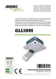
Thermostat knob (B)<br />
- Selection of the required<br />
room temperature.<br />
RED/BLUE/FUCHSIA Led (C)<br />
- It displays the HEATING/COOLING<br />
functioning mode required by the<br />
electronic thermostat and if the heating<br />
plant able to meet the request.<br />
12<br />
I<strong>UL</strong><strong>PC</strong>LJ 1002 - 6976408_01<br />
-<br />
La possibilità di rimuovere la bacinella e le coclee dei ventilatori<br />
ispezionabili (eseguibile solo da personale specializzato)<br />
consentono di eseguire una pulizia accurata anche<br />
delle parti interne, condizione necessaria per installazioni in<br />
luoghi molto affollati o che richiedono uno standard elevato<br />
di igiene.<br />
The quietness of the new centrifugal fan assembly is such<br />
that at operating speed you cannot tell when the ’OMNIA<br />
<strong>UL</strong> cuts in, the use of the electronic control panels avoids<br />
annoying noise typical of mechanical thermostats.<br />
The command panel with electronic thermostat is protected<br />
by a flap on the head.<br />
Electronic regulation of the temperature, automatic fan<br />
speed change, automatic season change and automatic turning<br />
on and off.<br />
The OMNIA <strong>UL</strong> fan<strong>coil</strong> has been design to meet all<br />
system requirements partly through its extensive range of<br />
accessories.<br />
Ease of installation that can be either horizontal or vertical,<br />
with reversible plumbing attachments at the installation<br />
phase.<br />
Pieno rispetto delle norme antinfortunistiche.<br />
Routine maintenance is limited to periodic cleaning of the<br />
air filter.<br />
+<br />
YELLOW Led (D)<br />
- When on it indicates that<br />
the PLASMACLUSTER and<br />
the ventilation have been<br />
activated by the electronic<br />
thermostat.<br />
- When flashing it indicates standby or<br />
autotest status.<br />
Selector knob(A)<br />
- OFF = Off.<br />
- AUTO =Automatic operation.<br />
- Manual speed selection:<br />
V1 = Minimun fan speed<br />
V2 = Mediun fan speed<br />
V3 = Maximun fan speed
USE (OMNIA <strong>UL</strong> <strong>PC</strong>)<br />
CONTROLS:<br />
Ventilation can only take place with the louver open.<br />
These must be opened <strong>manual</strong>ly.<br />
When the louver is closed, ventilation is shut down (the thermostat however remains operative,<br />
continually detecting room conditions for prompt restart when the louver is reopened).<br />
The “PLASMACLUSTER” purifier cuts in automatically when the ventilation comes on.<br />
On / Off<br />
OFF The fan<strong>coil</strong> is off.<br />
The unit will restart in heating mode (anti-freeze function) if room temperature drops below<br />
7°C and water temperature is suitable; in this case, the red LED lamp will flash.<br />
To restart the fan<strong>coil</strong>, rotate the knob to the operation mode required in AUTO position or in<br />
one of the three fan speeds.<br />
Speed selection<br />
AUTO The thermostat maintains the temperature of the setting by adjusting fan speed in automatic<br />
mode, according to the room temperature and the temperature setting.<br />
The thermostat maintains the temperature of the setting by on-off cycles, using<br />
minimum, medium and maximum fan speeds as required.<br />
Temperature selection<br />
Permits the required temperature to be set.<br />
The temperature corresponding with the selector set at the central position depends on<br />
the active functioning mode (Hot 20°C, Cold 25°C).<br />
The differences of minimum and maximum temperature with respect to the central position are<br />
+8°C and -8°C<br />
Season change<br />
The electronic thermostat automatically sets the Cold and Hot functioning according to the<br />
temperature of the water in the system. With special settings (that can only be programmed<br />
by qualified staff), the seasonal change is possible by adjusting the temperature selector, the<br />
backlit displays can vary from the standard configuration.<br />
BACKLIT DISPLAY FOR THE USER (<strong>UL</strong> <strong>PC</strong> in the standard configuration)<br />
The LED indicator lamp C indicates the current operating<br />
mode:<br />
RED On indicates Heating operation<br />
(heating).<br />
Flashing indicates antifreeze mode.<br />
RED -FUCHSIA Alternate flashing of the two colours : indicates<br />
operation when hot (heating) but the water<br />
in the system has not yet reached the temperature<br />
suitable for enabling the ventilation.<br />
BLUE On indicates Cooling operation<br />
(cooling).<br />
BLUE -FUCHSIA Alternate flashing of the two colours :<br />
indicates operation when cold (cooling) but the<br />
water in the system has not yet reached the temperature<br />
suitable for enabling the ventilation.<br />
FUCHSIA flashing: fan <strong>coil</strong> in autotest function.<br />
LED D: a ventilation request has been made by the electronic<br />
thermostat:<br />
YELLOW On: Plasmacluster operating and ventilation<br />
enabled, this indicates that the thermostat has<br />
detected a room temperature that requires the<br />
ventilation to cut in, the PLASMACLUSTER is<br />
activated at the same time as the ventilation.<br />
Off: ventilation not enabled, it indicates that the<br />
louvre is closed and that the ventilator cannot start.<br />
If the louvre is open, the led (D) off indicates that<br />
selector switch A is in the OFF position or that the<br />
room thermostat does not require start up.<br />
Slow flashing: fan <strong>coil</strong> in standby, the ventilation is<br />
not enabled because the water circulating in the<br />
plant has not yet reached the right functioning<br />
temperature.<br />
Cyclical flashing (a given no. of flashes): fan <strong>coil</strong> in<br />
Autotest function, the number of flashes indicates<br />
the component tested.<br />
I<strong>UL</strong><strong>PC</strong>LJ 1002 - 6976408_01<br />
-<br />
-<br />
-<br />
+<br />
+<br />
+<br />
13
OPERATION<br />
OMNIA <strong>UL</strong> <strong>PC</strong> fan<strong>coil</strong>s are delivered ready to operate<br />
in standard configuration, though can be adjusted by the<br />
installation technician to specific requirements by means of<br />
dedicated accessories and configuration of functions at the<br />
internal dipswitches (see DIPSWITCH CONFIGURATION).<br />
Response to controls is immediate, except in special cases.<br />
Unit types<br />
OMNIA <strong>UL</strong> <strong>PC</strong> fan<strong>coil</strong>s are designed for twin-tube units, in<br />
the following types:<br />
- without valve;<br />
- with 2-way valve (water probe below valve);<br />
- with 3-way valve (water probe above valve).<br />
Ventilation<br />
Ventilation speed can be controlled either <strong>manual</strong>ly by setting<br />
the selector switch A to position V1, V2 or V3 (the fan<br />
operates in on-off cycles according to the speed selected),<br />
or automatically when the selector switch is set to the AUTO<br />
position (fan speed is controlled by the thermostat according<br />
to room temperature detected).<br />
On systems with a valve (dip1 = ON) and a Water Probe<br />
installed upstream of the valve (dip2 = ON), a delay (maximum<br />
2'40'') can be set between the valve switching on and<br />
the fan starting up (pre-heating of the heat exchanger).<br />
Ventilation can only take place with the louvers open. On<br />
models where the louvers are not motorised these must be<br />
opened <strong>manual</strong>ly.<br />
Season changeover<br />
The thermostat changes seasonal operation automatically.<br />
Season changeover takes place according to the water temperature<br />
detected in the unit.<br />
According to the dipswitch settings, two types of season<br />
change (water side) are possible:<br />
- Dip1 = OFF, Dip2 = OFF (standard configuration) with<br />
minimum/maximum temperature control only;<br />
- Dip1 = ON, Dip2 = ON (configuration with three-way<br />
valve and probe before the valve) with minimum/maximum<br />
temperature control and <strong>coil</strong> preheating (fan operation delay<br />
maximum 2'40").<br />
n the case of special units with water probe below the valve<br />
or fitted with 2-way valve, season change takes place from the<br />
air side, through operation of the temperature selector switch.<br />
Though this setting allows use of the fan<strong>coil</strong> in pre-existing 2way<br />
valve plants, it is not recommended, given that it hampers<br />
the operation of the electronic thermostat (the Heating/Cooling<br />
mode status display by LED is altered, depending on the temperature<br />
selected and the room air temperature).<br />
Water temperature controls<br />
The thermostat only enables fan operation when the water<br />
temperature is suitable for Heating or Cooling mode.<br />
Both the hot and cold starting up temperatures can be set to<br />
suit the conditions under which the system operates.<br />
The hot starting up threshold can be selected using Dip 5:<br />
OFF position for normal Heat (39°C) and ON position for<br />
reduced Heat (35°C).<br />
The cold starting up threshold can be selected using Dip 6:<br />
OFF position for normal Cold (17°C) and ON position for<br />
reduced Cold (22°C).<br />
If the water temperature is not suitable for the operating<br />
mode selected, LED lamp C on the control panel flashes<br />
alternately pink, red and blue next to the relative mode; this<br />
display is switched off when Dip1 = ON and Dip 2 = OFF.<br />
Valve control<br />
La valvola può essere controllata in due modalità:<br />
- optimised: this mode exploits the capacity of the fan<strong>coil</strong><br />
(Heating) to supply heat even when fan operation has been<br />
shut down; during Cooling, ventilation continues for control<br />
of room temperature by the valve.<br />
- normal: the valve opens or closes, depending on whether<br />
the fan starts up or shuts down.<br />
Probe correction<br />
The required correction to be applied to the ambient probe<br />
can be selected.<br />
14<br />
I<strong>UL</strong><strong>PC</strong>LJ 1002 - 6976408_01<br />
Frost Protection<br />
This function prevents room temperature from dropping<br />
below an ambient temperature of 7°C (even when the fan<strong>coil</strong><br />
is off and selector switch A is in the OFF position).<br />
In the event that room temperature drops below 7°C, the<br />
thermostat starts up the fan<strong>coil</strong> in heating mode at a temperature<br />
setting of 12°C and fan operation set to AUTO (if<br />
permitted by water temperature, the unit is connected to<br />
the power supply and the louvers are open, in the case of<br />
<strong>manual</strong> units).<br />
Frost protection mode is deactivated when room temperature<br />
rises above 9°C.<br />
Emergency mode<br />
In the event of failure of the SA ambient sensor, the thermostat<br />
goes into Emergency mode as indicated by the yellow<br />
LED (D) flashing. Under these conditions the control panel<br />
operates in the following way:<br />
- with selector switch (A) in OFF position: la valvola acqua è<br />
chiusa ed il fan off.<br />
- with selector switch (A) in AUTO, V1, V2 or V3 position: la<br />
valvola acqua è sempre aperta ed il the fan performs on-off<br />
cycles; in this case, the power supplied by the terminal is<br />
controlled <strong>manual</strong>ly by means of the temperature selector<br />
switch (B): rotate the switch to right to increase cycle duration,<br />
or to the left to reduce it.<br />
Plasmacluster<br />
The Plasmacluster air purifier is activated at the same time as<br />
the ventilation whether hot or cold.<br />
The functioning of the device is indicated by a yellow Led<br />
coming on the control panel.<br />
The Plasmacluster purification breaks down the water and<br />
oxygen molecules normally present in ambient air (“dampness”<br />
and “oxygen”), into positive and negative ions. These<br />
ions liberated into the air will stick to the molecules of the<br />
polluting substances and by being recombined (once activated)<br />
decomposes them into non-toxic sub-products (water,<br />
oxygen and carbon dioxide etc..).<br />
PACKAGING<br />
The fan<strong>coil</strong>s are sent with standard packaging consisting of<br />
protective shells and boxes.<br />
INSTALLATION OF THE UNIT<br />
WARNING: before carrying out any work, put the proper<br />
individual protection devices on.<br />
WARNING: before carrying out any work, make sure the<br />
electrical power is unplugged.<br />
CAUTION: electrical connections, the installation of the<br />
fan <strong>coil</strong>s and their accessories must only be carried out<br />
by people with the proper technical and professional qualifications<br />
for the installation, conversion, expansion and<br />
maintenance of the machinery and able to check that it is<br />
working properly and safe.<br />
Install the fan<strong>coil</strong> in a position that will facilitate routine<br />
(filter cleaning) and special maintenance, and easy access<br />
to the air breather valve on the side of the unit (connections<br />
side).<br />
Note that certain operating conditions could lead to the formation<br />
of condensate on the unit housing with subsequent<br />
dripping, or faults to the water circuit or condensate drainage<br />
could cause liquids to overflow. For these reasons, avoid<br />
installing the unit on surfaces damageable by moisture.<br />
Make sure that the unit is installed in a site where the<br />
ambient temperature is inside the minimum and maximum<br />
limits 0 - 45°C (
unit on the wall.<br />
- Make water connections. To make the air vent from the<br />
<strong>coil</strong> easier, you are recommended to connect the outlet<br />
water pipe with the connection positioned on the top,<br />
the possible inversion will not affect the proper unit operation.<br />
The position and diameter of water connectors are given<br />
in the dimensional data.<br />
Insulation of water lines is recommended. Install the condensate<br />
water collection tray (optional accessory) to prevent<br />
dripping during cooling operation.<br />
N.B.: Use a tool to break the push-out in the drip tray<br />
(water connection side) before connecting the condensate<br />
drainage.<br />
Size and arrange the condensate drain system in such a<br />
way as to ensure a gradient of at least 1%. If drainage is<br />
emptied into the sewerage system, fit a siphon to prevent<br />
the return of unpleasant odours into the room.<br />
Test the seal of water and condensate drainage connections.<br />
- Fit accessories (as applicable).<br />
- To modify the settings of the electronic thermostat, modify the<br />
dip switches from the relevant window at the back of the control<br />
panel, (see the “DIP-SWITCH SETTINGS” chapter).<br />
- Make all wiring connections as shown in wiring diagrams<br />
and the section "ELECTRICAL CONNECTIONS". Connect<br />
the control panel to the connector on the inside of the<br />
fan<strong>coil</strong>, then earth the unit.<br />
- Check the proper functioning of the fan <strong>coil</strong> by means of the<br />
Autotest procedure.<br />
- Re-install the casing.<br />
- Check that the fan<strong>coil</strong> operates correctly.<br />
WARNING: the filter may only be removed from the sealed box<br />
and fitted to the unit at the time it will be used for the first<br />
time.<br />
ELECTRICAL CONNECTIONS<br />
WARNING: always check that the electricity supply to the unit<br />
has been disconnected before carrying out any operations.<br />
In the specific case of electrical connections, the following<br />
must be checked:<br />
- Measurement of the isolation resistance on the electrical<br />
system.<br />
- Testing of the continuity of protection conductors.<br />
Electric circuits are connected to mains voltage of 230V;<br />
make sure that all components correspond to this voltage.<br />
CONNECTING CABLES<br />
Use H05V-K or N07V-K cables with insulation 300/500 V in<br />
conduit or raceway. All cables exterior to the fan<strong>coil</strong> must be<br />
protected in this way.<br />
Only use power cables with a minimum cross section of<br />
1.5mm 2<br />
Position cable lengths not protected by the conduit or<br />
OMNIA <strong>UL</strong> <strong>PC</strong><br />
raceway in such a way as to ensure that they are not subject<br />
to stress, twisting or external agents.<br />
When making connections, always refer to the wiring diagrams<br />
supplied with the unit and shown in this document.<br />
To protect fan <strong>coil</strong>s against short circuits, always fit the<br />
power cable to the units with 2A 250V (IG) thermo-magnetic<br />
all-pole switches with a minimum contact gap of 3 mm.<br />
Each control panel controls a single fan<strong>coil</strong>.<br />
COIL ROTATION<br />
If <strong>coil</strong> rotation is required when making water connections,<br />
remove the unit housing then proceed as follows:<br />
- disconnect wires from the terminal block;<br />
- remove the probe from the <strong>coil</strong>;<br />
- remove the screws securing the drip tray, then lift it out;<br />
- remove the screws securing the <strong>coil</strong>, then lift it out;<br />
- remove the push-outs on the right side;<br />
- rotate the <strong>coil</strong>, then secure it in place with the screws previously<br />
removed;<br />
- refit the drip tray then secure it with the screws; fit the plastic<br />
plugs (supplied) in the holes left vacant by the water line<br />
connections.<br />
All trays are prearranged for condensate drainage on either<br />
side.<br />
N.B.: Before connecting up the condensate drain, use a<br />
tool to open the diaphragm in the tray (where fitted) on the<br />
water connection side. Seal the unused drain outlet using<br />
the plug provided.<br />
Remove the electrical connections from the right hand side.<br />
Remove the push-out and move the cable sheath from the<br />
right to the left.<br />
- Move the motor cable to the left hand side, passing it<br />
through the protective sheath.<br />
- Move the terminal board and the earthing pin to the left<br />
hand side.<br />
- Restore the motor cable electrical connections.<br />
- Insert the battery probe.<br />
- Remove the switch cards from the right hand element.<br />
- Disconnect the microswitch.<br />
- Remove the reinforcing stay.<br />
- Pass the wire for the microswitch through the opening on<br />
the opposite side.<br />
- Secure the reinforcing stay.<br />
- Fit the thermostat card on the left hand element and fit the<br />
knobs.<br />
- Restore the control panel electrical connections.<br />
L<br />
N<br />
I<strong>UL</strong><strong>PC</strong>LJ 1002 - 6976408_01<br />
15
DIPSWITCH<br />
* = Factory setting<br />
EXAMPLES OF SYSTEM SETTING<br />
16<br />
OFF<br />
ON<br />
OFF<br />
DIP-SWITCH CONFIGURATION<br />
ON<br />
I<strong>UL</strong><strong>PC</strong>LJ 1002 - 6976408_01<br />
* No shut off valve<br />
* Temperature water on exchanger or on 2-way valve<br />
* Optimised valve control<br />
* Optimised probe correction<br />
* Enable standard set heating<br />
* Enable standard set cooling<br />
* Werkseinstellung<br />
Plasmacluster disabled<br />
1 2<br />
3 4 5 6 7 8<br />
Configuration of dipswitches must only be carried out by<br />
qualified personnel during unit installation.<br />
Adjust the dipswitches inside the thermostat for the following<br />
functions:<br />
(Dip 1 and 2 must have the same configuration for a correct<br />
functioning).<br />
Dipswitch 1 (Default OFF )<br />
Shut-off valve:<br />
- if not fitted, set to OFF<br />
- if fitted, set to ON<br />
Dipswitch 2 (Default OFF )<br />
Water temperature probe:<br />
- if probe is below valve or 2-way valve is fitted, set to OFF<br />
- if probe is above valve or 3-way valve is fitted, set to ON<br />
Combination of Dip.1 ON with Dip.2 OFF is not recommended<br />
(used only for installation on two units using only<br />
pre-existing 2-way valves).<br />
Dipswitch 3 (Default OFF)<br />
Valve control:<br />
- for Optimised valve, set to OFF<br />
- for Normal valve, set to ON<br />
* Plasmacluster enabled<br />
Enable reduced set cooling<br />
Enable reduced set heating<br />
Standard probe control<br />
Standard valve control<br />
Temperature probe before valve or 3-Way valve<br />
Shut off valve is present<br />
AUTOTEST FUNCTION<br />
This function is designed to check the operation of the fan, valves and heaters.<br />
To run the Autotest function, proceed as follows:<br />
1) Selector switch B in central position.<br />
2) Selector switch A in OFF position.<br />
3) Adjust the selector switch A rapidly to obtain the following sequence:<br />
AUTO → OFF → V1 → OFF → V2 → OFF → V3 → OFF.<br />
At this stage the unit sets to AUTOTEST mode (PINK LED flashing).<br />
4) With the selector switch A in the AUTO position, the valve is activated. Yellow LED<br />
(D) runs 1-flash cycles.<br />
5) With the selector switch A in the V1 position, minimum speed V1 is activated. Yellow<br />
LED (D) runs 2-flash cycles.<br />
6) With the selector switch A in the V2 position, the medium speed V2 is activated.<br />
Yellow LED (D) runs 3-flash cycles.<br />
7) With the selector switch A in the V3 position, the maximum speed V3 is activated.<br />
Yellow LED (D) runs 4-flash cycles.<br />
The Autotest function automatically stops after one minute.<br />
Dipswitch 4 (Default OFF)<br />
Probe (Heating) correction to compensate overheating of<br />
metal structure:<br />
- for optimised correction, set to OFF<br />
- for fixed correction, set to ON<br />
Dipswitch 5 (Default OFF)<br />
Enable Heating mode according to water temperature:<br />
- for Normal Heating mode (39°C), set to OFF<br />
- for Reduced Heating (35°C), set to ON<br />
Dipswitch 6 (Default OFF)<br />
Enable Cooling mode according to water temperature:<br />
- for Normal Cooling (17°C), set to OFF<br />
- for Reduced Cooling (22°C), set to ON<br />
Dip 7 (Default OFF)<br />
Factory settings OFF<br />
Dip 8 (Default OFF )<br />
Plasmacluster enabling:<br />
-Plasmacluster enabled ON<br />
-Plasmacluster disabled OFF<br />
Dip 8 Dip 7 Dip 2 Dip 1 System types<br />
ON OFF OFF OFF Two-pipe system and active Plasmaculter.<br />
ON OFF ON ON two pipe system with three-way valve, upline probe and Plasmaculter active.<br />
B<br />
A<br />
-<br />
+
IMPORTANT MAINTENANCE INFORMATION<br />
WARNING: the filter may only be removed from the sealed box and fitted to the unit at the time it will be used for the<br />
first time. The electrostatic charge when functioning normally runs out after around two years from the opening of the<br />
sealed box. After this date the filter maintains its mechanical function. You are advised to substitute a new electrostatically<br />
pre-charged filter that you can find at our assistance centres.<br />
WARNING: The fan<strong>coil</strong> is connected to the power supply and a water circuit. Operations performed by persons without<br />
the required technical skills can lead to personal injury to the operator or damage to the unit and surrounding objects.<br />
POWER THE FANCOIL WITH SINGLE-PHASE 230 V ONLY<br />
Use of other power supplies could cause permanent damage to the fan<strong>coil</strong>.<br />
NEVER USE THE FANCOIL FOR APPLICATIONS FOR WHICH IT WAS NOT DESIGNED<br />
Do not use the fan<strong>coil</strong> in husbandry applications (e.g. incubation).<br />
AIR THE ROOM<br />
Periodically air the room in which the fan<strong>coil</strong> has been installed; this is particularly important if the room is occupied by<br />
many people, or if gas appliances or sources of odours are present.<br />
CORRECTLY ADJUST THE TEMPERATURE<br />
Room temperature should be regulated to ensure maximum comfort to persons present, particularly in the case of the elderly,<br />
infants and invalids. Prevent temperature fluctuations between indoors and outdoors greater than 7 °C during summer.<br />
Note that very low temperatures during summer will lead to greater electricity consumption.<br />
ORIENT AIR FLOW CORRECTLY<br />
Air delivered by the fan<strong>coil</strong> should not be oriented directly at people; even if air temperature is greater than room temperature,<br />
it can cause a cold sensation and consequently discomfort.<br />
DO NOT USE HOT WATER<br />
When cleaning the indoor unit, use rags or soft sponges soaked in warm water (no higher than 40°C).<br />
Do not use chemical products or solvents to clean any part of the fan<strong>coil</strong>.<br />
Do not splash water on interior or exterior surfaces of the fan<strong>coil</strong>; danger of short circuit.<br />
PERIODICALLY CLEAN THE FILTER<br />
Frequent cleaning of the filter will ensure more efficient unit operation.<br />
Check whether the filter requires cleaning; if it is particularly dirty, clean it more often.<br />
Clean the filter frequently. Use a vacuum cleaner to remove built up dust. Avoid water or detergents if possible since they<br />
greatly accelerate loss of the filter's electrostatic charge.<br />
After cleaning and drying the filter, fit it on the fan<strong>coil</strong> by following the removal procedure in reverse order.<br />
SPECIAL CLEANING<br />
The removable drip tray and fan volute ensure thorough cleaning of the unit (by specifically trained personnel), essential for<br />
installations in venues subject to crowding or in those with special hygiene requirements.<br />
DURING UNIT OPERATION<br />
Always leave the filter on the fan<strong>coil</strong> during operation (otherwise dust in the air could soil the surface of the <strong>coil</strong>).<br />
IT IS NORMAL<br />
During cooling, water vapour may be present in the air delivery.<br />
During heating operation a light rustling sound may be perceived near the fan<strong>coil</strong>.<br />
Sometimes the fan<strong>coil</strong> can give off unpleasant odours due to the accumulation of substances present in the room: air the<br />
room and clean the filter more often.<br />
OPERATING LIMITS<br />
Maximum water inlet temperature 80 °C<br />
Maximum working pressure 8 bar<br />
Minimum average water temperature<br />
To prevent the formation of condensation on the exterior of the unit while the fan is operating, the average water temperature<br />
should not drop beneath the limits shown in the table below, determined by the ambient conditions. These limits refer to<br />
unit operation with fan at minimum speed. Note that condensation may form on the exterior of the unit if cold water circulates<br />
through the <strong>coil</strong> while the fan is off for prolonged periods of time, so it is advisable to fit the additional three-way valve.<br />
MINIMUM AVERAGE WATER TEMPERATURE<br />
Dry bulb temperature °C<br />
21 23 25 27 29 31<br />
15 3 3 3 3 3 3<br />
17 3 3 3 3 3 3<br />
Wet bulb temperature °C 19 3 3 3 3 3 3<br />
21 6 5 4 3 3 3<br />
23 - 8 7 6 5 5<br />
I<strong>UL</strong><strong>PC</strong>LJ 1002 - 6976408_01<br />
17
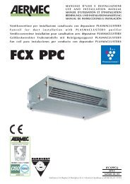
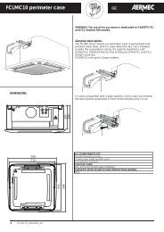
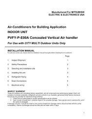
DATI DIMENSIONALI DIMENSIONS DIMENSIONS ABMESSUNGEN DIMENSIONES [mm]<br />
36<br />
OMNIA <strong>UL</strong>M<br />
OUT<br />
IN<br />
I<strong>UL</strong><strong>PC</strong>LJ 1002 - 6976408_01<br />
38<br />
149<br />
125<br />
ZU<br />
93<br />
207<br />
242<br />
80<br />
50mm<br />
Peso ventilconvettore senza zoccoli Weight of fan <strong>coil</strong> without feet<br />
Poids ventilo-convecteur sans pieds Gewicht Gebläsekonvektor ohne Sockel Peso convector ventilador sin zócalo<br />
426<br />
465<br />
100 mm<br />
50 mm<br />
Mod <strong>UL</strong>M 11 <strong>UL</strong>M 16 <strong>UL</strong>M 26 <strong>UL</strong>M 36<br />
Larghezza Width Largeur Breite Longitud A 640 750 980 1200<br />
Altezza Height Hauter Höhe Altura H 606 606 606 606<br />
Profondità Depth Profondeur Tiefe Profundidad L 173 173 173 173<br />
Altezza zoccoli Feet height Hauter pieds Höhe Sockel Altura zócalos Z 94 94 94 94<br />
Peso Weight Poids net Nettogewicht Peso [kg] 12,5 13,5 16,5 19,5<br />
Attacchi batteria (femmina) Coil connection (female)<br />
Raccords batterie (femelle) Anschlüsse des Warmetäuschers (Innengewinde) Conexiones batería (hembra)<br />
Mod. <strong>Omnia</strong> <strong>UL</strong> 11 <strong>Omnia</strong> <strong>UL</strong> 16 <strong>Omnia</strong> <strong>UL</strong> 26 <strong>Omnia</strong> <strong>UL</strong> 36<br />
3 R 1/2” 1/2” 1/2” 1/2”
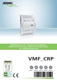
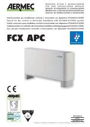
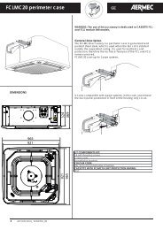
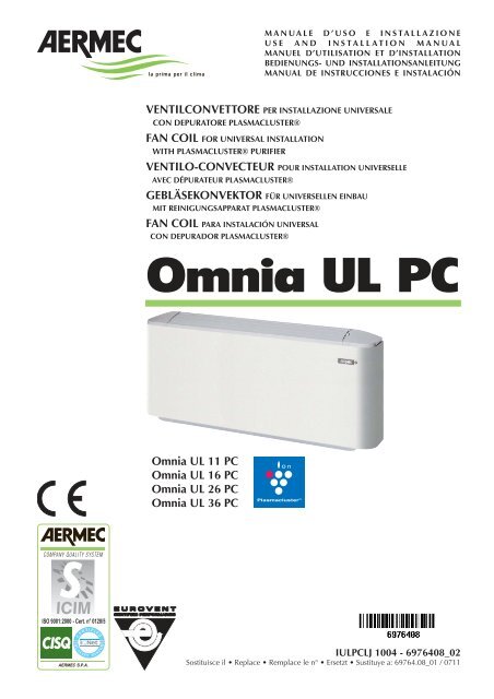
DATI DIMENSIONALI DIMENSIONS DIMENSIONS ABMESSUNGEN DIMENSIONES [mm]<br />
10<br />
10<br />
6,5<br />
14,5<br />
6,5<br />
544<br />
264<br />
97<br />
31<br />
120<br />
120<br />
r49<br />
5<br />
72 29<br />
5<br />
5<br />
72<br />
26<br />
64<br />
65 54<br />
A<br />
B<br />
C<br />
= =<br />
1 Testata con alette orientabili Went with adjustable slats Tête à ailettes orientables<br />
Oberer Teil mit verstellbaren Lamellen Cabeza con aleta orientable<br />
2 Mobile di copertura Cabinet Meuble de couverture Gehäuse Mueble de cobertura<br />
3 Struttura portante Bearing structure Structure portante Trägerstruktur Estructura portante<br />
4 Zoccolo ZU Feet ZU Pieds ZU Sockel ZU Zócalo ZU<br />
5 Spazio per i collegamenti Free space available for connection Espace puor branchements<br />
Raum für die Anschlüsse Espacio para las conexiones<br />
E<br />
D<br />
³80<br />
145 196<br />
=<br />
=<br />
C<br />
B<br />
A<br />
=<br />
D<br />
3<br />
=<br />
80<br />
I<strong>UL</strong><strong>PC</strong>LJ 1002 - 6976408_01<br />
1<br />
5<br />
5<br />
4<br />
96 (ZU)<br />
5<br />
2<br />
93<br />
106<br />
148 (ZU) 10<br />
421<br />
Mod. <strong>UL</strong> 11<strong>PC</strong> <strong>UL</strong> 16<strong>PC</strong> <strong>UL</strong> 26<strong>PC</strong> <strong>UL</strong> 36<strong>PC</strong><br />
A 640 750 980 1200<br />
B 384 494 725 945<br />
C 360,5 470,5 701,5 921,5<br />
D 288 398 629 849<br />
E 394 504 735 955<br />
37
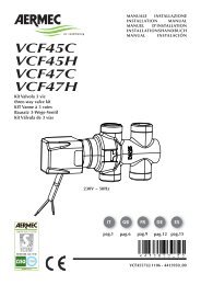
SCHEMI ELETTRICI WIRING DIAGRAMS SCHEMAS ELECTRIQUES SCHALTPLÄNE ESQUEMAS ELÉCTRICOS<br />
LEGENDA READING KEY LEGENDE LEGENDE LEYENDA<br />
IG = Interruttore generale Main switch<br />
Interupteur général Hauptschalter Interruptor general<br />
M = Morsettiera Terminal board<br />
Boitier Klemmleiste Caja de conexiones<br />
MS = Microinterruttore Microswitch<br />
Microinterrupteur Mikroschalter Microinterruptor<br />
MV = Motore ventilatore <strong>Fan</strong> motor Moteur ventilateur<br />
Ventilatormotor Motor ventilador<br />
PE = Collegamento di terra Earth connection<br />
Mise à terre Erdanschluss Toma de tierra<br />
SA = Sonda ambiente Room sensor Sonde ambiante<br />
Raumtemperaturfuhler Sonda ambiente<br />
SC = Scheda di controllo Electronic control board<br />
Platine de contrôle Steuerschaltkreis Tarjeta de control<br />
SW = Sonda minima temperatura acqua<br />
Water low temperature sensor<br />
Sonde eau<br />
Fühler Wassertemperatur<br />
Sonda mínima temperatura del agua<br />
OMNIA <strong>UL</strong> <strong>PC</strong><br />
38<br />
SA<br />
SA<br />
10k<br />
T °C<br />
ON/VEL<br />
SC<br />
V1<br />
V2<br />
V3<br />
Y1<br />
Y2<br />
L<br />
PE<br />
N<br />
SW<br />
M<br />
SW<br />
10k<br />
I<strong>UL</strong><strong>PC</strong>LJ 1002 - 6976408_01<br />
BI<br />
AR AR<br />
1<br />
L N Y N<br />
2<br />
NE<br />
3<br />
BL<br />
VC/F<br />
BL<br />
GR<br />
4<br />
ROS<br />
1 3 5 6 7<br />
CLUSTER<br />
GR<br />
5<br />
MS<br />
ROS<br />
6<br />
BL MA<br />
NE RO<br />
7<br />
VCF = Valvola solenoide Solenoid valve<br />
Vanne solenoide Magnetventil Válvula solenoide<br />
= Componenti forniti optional Optional components<br />
Composants en option Optionsteile<br />
Componentes opcionales facilitados<br />
= Collegamenti da eseguire in loco<br />
On-site wiring<br />
Raccordements à effectuer in situ<br />
Vor Ort auszuführende Anschlüsse<br />
Conexiones que deben realizarse in situ<br />
AR = Arancio Orange Orange Orange Naranja<br />
BI = Bianco White Blance Weiss Blanco<br />
BL = Blu Blue Bleu Blau Azul<br />
GR = Grigio Grey Gris Gray Gris<br />
GV = Giallo-Verde Yellow-Green<br />
Jaune-Vert Gelb-Grün Azul-verdoso<br />
MA = Marrone Brown Marron Braun Marrón<br />
NE = Nero Black Noir Schwarz Negro<br />
RO = Rosso Red Rouge Rot Rojo<br />
8<br />
MAX<br />
9<br />
MED<br />
M<br />
1<br />
MV<br />
10<br />
MIN<br />
BL NE MA RO<br />
PE<br />
N<br />
L<br />
IG<br />
230V ~ 50Hz<br />
Gli schemi elettrici sono soggetti ad aggiornamento; è opportuno fare riferimento allo schema elettrico allegato all' apparecchio.<br />
Wiring diagrams may change for updating. It is therefore necessary to refer always to the wiring diagram inside the units.<br />
Les schémas électriques peuvent être modifies en conséquence des mises à jour. Il faut toujours se référer aux schémas électriques dans les appareils.<br />
Die Schaltschemas können geändert werden; es empfiehlt sich immer auf das mit dem Gerät verpackte El. Schaltschema zu beziehen.<br />
Los esquemas eléctricos están sujetos a actualizaciones; es necesario consultar el esquema eléctrico adjunto al aparato.
PROBLEMA PROBLEM<br />
PROBLEME PROBLEM<br />
PROBLEMA<br />
Poca aria in uscita.<br />
Feeble air discharge.<br />
Il y a peu d’air en sortie.<br />
Schwacher Luftstrom am Austritt.<br />
Poco aire en salida.<br />
Non fa caldo.<br />
It does not heat.<br />
Pas de chaleur.<br />
Keine Heizung.<br />
No hace calor.<br />
Non fa freddo.<br />
It does not cool.<br />
Pas de froid.<br />
Keine Kühlung.<br />
No hace frío.<br />
Il ventilatore non gira.<br />
The fan does not turn.<br />
Le ventilateur ne tourne pas.<br />
Ventilator Arbeitet nicht.<br />
El ventilador no gira.<br />
Fenomeni di condensazione<br />
sulla struttura esterna dell’apparecchio.<br />
Condensation on the unit<br />
cabinet.<br />
Phénomènes de condensation<br />
sur la structure exterieure<br />
de l’appareil.<br />
Kondenswasserbildung am<br />
Gerät.<br />
Fenómenos de condensación<br />
en la estructura externa del<br />
aparato.<br />
PROBABILE CAUSA PROBABLE CAUSE<br />
CAUSE PROBABLE MÖGLICHE URSACHE<br />
CAUSA PROBABLE<br />
Errata impostazione della velocità sul pannello comandi.<br />
Wrong speed setting on the control panel.<br />
Mauvaise préselection de la vitesse sur le panneau de commandes.<br />
Falsche Geschwindigkeitseinstel lung am Bedien paneel.<br />
Programación errada de la velocidad en el tablero de mandos.<br />
Filtro intasato.<br />
Blocked filter.<br />
Filtre encrassé.<br />
Filter verstopft.<br />
Filtro atascado.<br />
Ostruzione del flusso d’aria (entrata e/o uscita).<br />
Obstruction of the air flow (inlet and/or outlet).<br />
Obstruction du flux d’air (entrée/sortie).<br />
Luftstrom behindert (Eintritt bzw. Austritt).<br />
Obstrucción del chorro del aire (entrada y/o salida).<br />
Mancanza di acqua calda.<br />
Poor hot water supply.<br />
Il n’y a pas d’eau chaude.<br />
Kein Warmwasser.<br />
Falta de agua caliente.<br />
Impostazione errata del pannello comandi.<br />
Wrong setting on control panel.<br />
Mauvaise présélection sur le panneau de commandes.<br />
Falsche Einstellung am Bedien paneel.<br />
Programación errada del tablero de mandos.<br />
Mancanza di acqua fredda.<br />
Poor chilled water supply.<br />
Il n’y a pas d’eau froide.<br />
Kein Kaltwasser.<br />
Falta de agua fría.<br />
Impostazione errata del pannello comandi.<br />
Wrong setting on control panel.<br />
Mauvaise présélection sur le panneau de commandes.<br />
Falsche Einstellung am Bedien paneel.<br />
Programación errada del tablero de mandos.<br />
Mancanza di corrente.<br />
No current.<br />
l n’y a pas de courant.<br />
Kein Strom.<br />
Falta de corriente.<br />
L’acqua non ha raggiunto la temperatura d’esercizio.<br />
The water has not reached operating temperature.<br />
L'eau n'a pas atteint la température de service.<br />
Das Wasser hat die Betriebstemperatur nicht erreicht.<br />
El agua no ha alcanzado la temperatura de ejercicio.<br />
Sono state raggiunte le condizioni limite di temperatura<br />
e umidità descritte in “MINIMA TEMPERATURA MEDIA<br />
DELL’ACQUA”.<br />
The limit conditions of temperature and humidity indicated in<br />
“MINIMUM AVERAGE WATER TEMPERATURE” have been<br />
reached.<br />
On a atteint les conditions limite de température et d’humidité<br />
indiquées dans “TEMPERATURE MINIMALE MOYENNE<br />
DE L'EAU”.<br />
Erreichen der maximalen Temperatur- und Feuchtigkeitswerte<br />
(siehe Abschnitt “DURCHSCHNITTLICHE MINDEST -<br />
WASSERTEMPERATUR”).<br />
Se han alcanzado las condiciones límites de temperatura<br />
y humedad descritas en “MÍNIMA TEMPERATURA MEDIA<br />
DEL AGUA".<br />
SOLUZIONE REMEDY<br />
SOLUTION ABHILFE<br />
SOLUCIÓN<br />
Scegliere la velocità corretta sul pannello comandi.<br />
Select the speed on the control panel.<br />
Choisir la vitesse sur la panneau de commandes.<br />
Die Geschwindigkeit am Bedien paneel wählen.<br />
Elegir la velocidad correcta en el tablero de mandos.<br />
Pulire il filtro.<br />
Clean the filter.<br />
Nettoyer le filtre.<br />
Filter reinigen.<br />
Limpiar el filtro.<br />
Rimuovere l’ostruzione.<br />
Remove the obstruction.<br />
Enlever l’objet faisant obstruction.<br />
Verstopfung beseitigen.<br />
Quitar la obstrucción.<br />
Controllare la caldaia.<br />
Control the boiler.<br />
Verifier la chaudière.<br />
Kaltwasserseitigen Wärmeaus tau scher kontrollieren.<br />
Comprobar el calentador.<br />
Impostare il pannello comandi.<br />
See control panel settings.<br />
Présélectionner au panneau de commandes.<br />
Richtige Einstellung am Bedien paneel vornehmen.<br />
Programar el tablero de mandos.<br />
Controllare il refrigeratore.<br />
Control the chiller.<br />
Vérifier le réfrigerateur.<br />
Kaltwasserseitigen Wärmeaus tau scher kontrollieren.<br />
Comprobar el refrigerador.<br />
Impostare il pannello comandi.<br />
See control panel settings.<br />
Présélectionner au panneau de commandes.<br />
Richtige Einstellung am Bedien paneel vornehmen.<br />
Programar el tablero de mandos.<br />
Controllare la presenza di tensione elettrica.<br />
Control the power supply.<br />
Contrôler l’alimentation électrique.<br />
Kontrollieren, ob Spannung anliegt.<br />
Comprobar la presencia de tensión eléctrica.<br />
Controllare la caldaia o il refrigeratore.<br />
Controllare il settaggio del termostato.<br />
Please check up the boiler or the chiller.<br />
Check up the thermostat settings.<br />
Contrôler la chaudière ou le refroidisseur.<br />
Contrôler le réglage du thermostat.<br />
Das Heiz- oder Kühlaggregat überprüfen.<br />
Die Einstellungen des Temperaturreglers überprüfen.<br />
Comprobar el calentador o el refrigerador.<br />
Comprobar la programación del termostato.<br />
Innalzare la temperatura dell’acqua oltre i<br />
limiti minimi descritti in “MINIMA TEMPERA-<br />
TURA MEDIA DELL’ACQUA”.<br />
Increase the water temperature beyond the<br />
minimum limits indicated in “MINIMUM<br />
AVERAGE WATER TEMPERATURE”.<br />
Elever la température de l’eau audelà des<br />
limites minimales indiquées dans “TEMPERA-<br />
TURE MINIMALE MOYENNE DE L'EAU”.<br />
Wassertemperatur über die um Abschnitt<br />
“DURCHSCHNITTLICHE MINDEST -<br />
WASSERTEMPERATUR” angegebenen min.<br />
Werte erhöhen.<br />
Aumentar la temperatura del agua por encima<br />
de los límites descritos en “Mínima temperatura<br />
media del agua”.<br />
Per anomalie non contemplate, interpellare tempestivamente il Servizio Assistenza.<br />
For anomalies don’t hesitate, contact the aftersales service immediately.<br />
Pour toute anomalie non répertoriée, consulter le service après-vente.<br />
Sich bei hier nicht aufgeführten Störungen umgehend an den Kundendienst wenden.<br />
En el caso de anomalías no contempladas, ponerse en contacto de inmediato con el Servicio de Asistencia.<br />
I<strong>UL</strong><strong>PC</strong>LJ 1002 - 6976408_01<br />
39
GARANZIA DI 3 ANNI<br />
La garanzia è valida solo se l’apparecchio è venduto ed installato sul territorio italiano. Il periodo decorre dalla data d’acquisto comprovata<br />
da un documento che abbia validità fiscale (fattura o ricevuta) e che riporti la sigla commerciale dell’apparecchio. Il documento dovrà essere<br />
esibito, al momento dell’intervento, al tecnico del Servizio Assistenza <strong>Aermec</strong> di zona.<br />
Il diritto alla garanzia decade in caso di:<br />
– interventi di riparazione effettuati sull’apparecchiatura da tecnici non autorizzati;<br />
– guasti conseguenti ad azioni volontarie o accidentali che non derivino da difetti originari dei materiali di fabbricazione.<br />
AERMEC Spa effettuerà la riparazione o la sostituzione gratuita, a sua scelta, delle parti di apparecchiatura che dovessero presentare difetti dei<br />
materiali o di fabbricazione tali da impedirne il normale funzionamento. Gli eventuali interventi di riparazione o sostituzione di parti dell’apparecchio,<br />
non modificano la data di decorrenza e la durata del periodo di garanzia. Le parti difettose sostituite resteranno di proprietà della<br />
AERMEC Spa.<br />
Non è prevista in alcun caso la sostituzione dell’apparecchio. La garanzia non copre le parti dell’apparecchio che risultassero difettose a causa<br />
del mancato rispetto delle istruzioni d’uso, di un’errata installazione o manutenzione, di danneggiamenti dovuti al trasporto, di difetti dell’impianto<br />
(es: scarichi di condensa non efficienti).Non sono coperte, infine, le normali operazioni di manutenzione periodica (es: la pulizia dei<br />
filtri d’aria) e la sostituzione delle parti di normale consumo (es: i filtri d’aria).<br />
Le agenzie di Vendita <strong>Aermec</strong> ed i Servizi di Assistenza Tecnica <strong>Aermec</strong> della vostra provincia sono negli Elenchi telefonici dei capoluoghi di<br />
provincia - vedi “<strong>Aermec</strong>” - e nelle Pagine Gialle alla voce “Condizionatori d’aria - Commercio”.<br />
<strong>Aermec</strong> partecipa al Programma di Certificazione EUROVENT. I prodotti interessati figurano nella Guida EUROVENT dei Prodotti Certificati.<br />
<strong>Aermec</strong> is partecipating in the EUROVENT Certification Programme. Products are as listed in the EUROVENT Directory of Certified Products.<br />
<strong>Aermec</strong> partecipe au Programme de Certification EUROVENT. Les produits figurent dans l’Annuaire EUROVENT des Produits Certifiés.<br />
<strong>Aermec</strong> ist am Zertifikations - Programm EUROVENT beteiligt. Die entsprechend gekennzeichneten Produkte sind im EUROVENT - Jahrbuch aufgefürt.<br />
AERMEC S.p.A. participa en el programa de certificación EUROVENT. Sus equipos aparecen en el directorio de productos certificados EUROVENT.<br />
I dati tecnici riportati nella presente documentazione non sono impegnativi.<br />
AERMEC S.p.A. si riserva la facoltà di apportare in qualsiasi momento tutte le modifiche ritenute necessarie per il miglioramento del prodotto.<br />
Les données mentionnées dans ce manuel ne constituent aucun engagement de notre part. <strong>Aermec</strong> S.p.A. se réserve le droit de modifier à tous moments les<br />
données considérées nécessaires à l’amelioration du produit.<br />
Technical data shown in this booklet are not binding.<br />
<strong>Aermec</strong> S.p.A. shall have the right to introduce at any time whatever modifications deemed necessary to the improvement of the product.<br />
Im Sinne des technischen Fortsschrittes behält sich <strong>Aermec</strong> S.p.A. vor, in der Produktion Änderungen und Verbesserungen ohne Ankündigung durchzuführen.<br />
ILos datos técnicos indicados en la presente documentación no son vinculantes.<br />
<strong>Aermec</strong> S.p.A. se reserva el derecho de realizar en cualquier momento las modificaciones que estime necesarias para mejorar el producto.<br />
AERMEC S.p.A.<br />
I-37040 Bevilacqua (VR) - Italia<br />
Via Roma, 996 - Tel. (+39) 0442 633111<br />
Telefax (+39) 0442 93730 - (+39) 0442 93566<br />
www .aermec. com