uhf tacsat /dama multi-service tactics, techniques ... - UHF-Satcom.com
uhf tacsat /dama multi-service tactics, techniques ... - UHF-Satcom.com uhf tacsat /dama multi-service tactics, techniques ... - UHF-Satcom.com
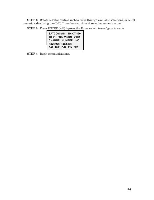
STEP 2. Rotate selector control knob to move through available selections, or select numeric value using the (D/D) ↑ number switch to change the numeric value. STEP 3. Press ENTER (X/E) ↓ press the Enter switch to configure to radio. SATCOM-M01 Rx-CT-120 TK 01 FSK VINSN V16K CHANNEL NUMBER: 100 R295.975 T262.375 S/G M/Z D/D P/N X/E STEP 4. Begin communications. F-9
1. Setting Up for DAMA Appendix G AN/WSC-3 At antenna controller, dial in the elevation and azimuth of satellite (such as, UHF follow-on 6) that the assigned channel is located. This setting depends on a ship’s location and it changes as the ship travels the ocean. There is an azimuth/elevation computation aid used to determine these values; each ship has one or more. a. Verify all power to the SA-2000 is on and all switches are turned on. b. On WSC-3 turn on or set as follows: (1) Turn power on. (2) Place standby/operate switch to operate. (3) Place control switch to local. (4) Place SATCOM/LOS switch to SATCOM. (5) Place modulation switch to EXT Modem. (6) For frequency select switches, dial the uplink frequency from Daily Comm Status message for the operational channel (for example, CONUS DAMA 1). (7) Completely turn power control knob clockwise, then turn back approximately one-quarter turn. (8) Partially extend radio from chassis. (a) Set SATCOM offset switch to offset 4. (This is the normal setting if the difference between uplink and downlink frequency is 41-MHz. Sometimes offset 3 is used if the difference is 33.6-MHz.) (b) This switch sets the downlink frequency in the radio. (c) Set TDMA/non-TDMA switch to TDMA position. (d) Return radio into chassis. c. At SB-4125 or SB-4126 IF patch panel, patch the TD-1271 Xmt to the transmitting radio. Patch the TD-1271 Rcv to the receiving radio. (Usually it is the same radio.) d. On the SB-4124 PATCH panel on the OK-454 or OK-455 equipment rack, ensure the TD-1271 XMT position is either normal thru’d or patched to the radio used to transmit. This TD-1271 XMT position is the top left position on the panel (A1J1). e. At the TD-1271. (1) Turn on the TD-1271. (2) Ensure the transmit inhibit switch is off. G-1
- Page 99 and 100: (d) Select the desired DAMA net by
- Page 101 and 102: completion of the communications. P
- Page 103 and 104: C-32 Figure C-12. MSG Service Call
- Page 105 and 106: C-34 Figure C-14. DAMA Service Stat
- Page 107 and 108: 1. Line of Sight (LOS) Operations A
- Page 109 and 110: k. Enter channel number (009 to 239
- Page 111 and 112: GUARD LIST VIEW 1 64000 ------ ----
- Page 113 and 114: (13) For DASA only, enter time requ
- Page 115 and 116: Message Action A Acquisition Failed
- Page 117 and 118: Message Action Aborted To:xxxx (Rea
- Page 119 and 120: Table D-7. Hot Keys, 5-kHz DAMA Key
- Page 121 and 122: (9) Enter configuration code, if re
- Page 123 and 124: (1) Select over-the-air, if the ter
- Page 125 and 126: 25-kHz AD HOC DAMA SETUP GUIDE - AN
- Page 127 and 128: 5C/D RADIOS 1. The following are re
- Page 129 and 130: Table D-8. 5-kHz DAMA Operations (S
- Page 131 and 132: Table D-8. 5-kHz DAMA Operations (S
- Page 133 and 134: E-2 d. Programming operating modes.
- Page 135 and 136: (12) After pushing the variable pos
- Page 137 and 138: d. radio. Prior to COLD START, pres
- Page 139 and 140: aa. INTKG should flash. Leave as is
- Page 141 and 142: 1. Skyfire Operator Training Append
- Page 143 and 144: The following message appears- F-2
- Page 145 and 146: F-4 CI MENU LOAD PRESETS LOADING PR
- Page 147 and 148: STEP 2. Rotate selector control kno
- Page 149: (1) On = Activates guard receiver.
- Page 153 and 154: (1) Enter *92 then depress the Ente
- Page 155 and 156: Appendix H EMI CHARACTERIZATION CHE
- Page 157 and 158: Appendix J CUT SHEETS The following
- Page 159 and 160: DAMA Database Set up Presets Mode P
- Page 161 and 162: Appendix K Prioritization Scheme Ta
- Page 163 and 164: References Joint CJCSM 3122.01, Joi
- Page 165 and 166: COCOM combatant command COMM commer
- Page 167 and 168: IO Indian Ocean IP internet protoco
- Page 169 and 170: P PAC Pacific PCC primary channel c
- Page 171 and 172: USARPAC United States Army, Pacific
- Page 173 and 174: attitude can be measured by the ang
- Page 175 and 176: channel control orderwire channel c
- Page 177 and 178: participate in a class broadcast fr
- Page 179 and 180: data stream into burst-formatted da
- Page 181 and 182: low power satellite A satellite wit
- Page 183 and 184: preamble Consists of a carrier segm
- Page 185 and 186: permit them to escape from the Sun
- Page 187 and 188: waveform The combination of baseban
- Page 189 and 190: COMSEC custodians, III-7 connection
- Page 191 and 192: DAMA, I-7, III-6, C-20 point-to-poi
- Page 193 and 194: data, I-24 data rate, I-24 disadvan
- Page 195: MARINE CORPS: PCN 144 00003 80 PIN:
STEP 2. Rotate selector control knob to move through available selections, or select<br />
numeric value using the (D/D) ↑ number switch to change the numeric value.<br />
STEP 3. Press ENTER (X/E) ↓ press the Enter switch to configure to radio.<br />
SATCOM-M01 Rx-CT-120<br />
TK 01 FSK VINSN V16K<br />
CHANNEL NUMBER: 100<br />
R295.975 T262.375<br />
S/G M/Z D/D P/N X/E<br />
STEP 4. Begin <strong>com</strong>munications.<br />
F-9


