TDMS Reader VI
TDMS Reader VI
TDMS Reader VI

You also want an ePaper? Increase the reach of your titles
YUMPU automatically turns print PDFs into web optimized ePapers that Google loves.
<strong>TDMS</strong> <strong>Reader</strong> <strong>VI</strong><br />
Goal<br />
Scenario<br />
Design<br />
Log data to a <strong>TDMS</strong> file and read the same <strong>TDMS</strong> file to access information<br />
about a specific channel.<br />
You are given a <strong>TDMS</strong> Logger <strong>VI</strong> that generates measurement data for any<br />
number of UUTs. The UUT measurement data consists of a time domain<br />
waveform and the power spectrum of a waveform.<br />
Run the <strong>TDMS</strong> Logger <strong>VI</strong> that accepts UUTs identified by serial numbers.<br />
The <strong>TDMS</strong> Logger <strong>VI</strong> retrieves the measurement data from the Generate<br />
Data <strong>VI</strong>, and logs the UUT data and additional properties to a <strong>TDMS</strong> file.<br />
The <strong>TDMS</strong> file contains the author, timestamp, and two channel<br />
groups—Time Data and Power Spectrum Data. Each group contains a<br />
channel for each UUT. The serial number of the UUT names each channel<br />
and contains the matching signal data.<br />
Saving data to a file serves no purpose unless you also can access the data.<br />
Create a reader <strong>VI</strong> to access data from the <strong>TDMS</strong> file you generated. The<br />
reader should return either time data or power spectrum data for a particular<br />
UUT serial number.<br />
<strong>TDMS</strong> File Reference Information<br />
File Level Information<br />
– Time Stamp—contains the current time.<br />
– Author—contains the test operator name, acquired through a front<br />
panel control.<br />
– The file contains two channel groups, one for time data and one for<br />
the power spectrum data.<br />
Channel Group Level Information<br />
– Name—contains Time Data or Power Spectrum Data. This<br />
identifies the channel group.<br />
– Each channel group should contain a channel for each UUT.<br />
© National Instruments Corporation 1 <strong>TDMS</strong> <strong>Reader</strong> <strong>VI</strong>
Channel Level Information<br />
– Name—contains the UUT Serial Number, which associates the<br />
numeric data with a particular unit.<br />
– Signal—contains an array of floating-point numeric data.<br />
– Several other properties, such as the signal minimum and maximum<br />
will automatically be calculated and added to the file.<br />
<strong>TDMS</strong> <strong>Reader</strong> Inputs and Outputs<br />
Table 1. <strong>TDMS</strong> <strong>Reader</strong> <strong>VI</strong> Inputs and Outputs<br />
Type Name Properties<br />
File Path Control <strong>TDMS</strong> File Path Default Value =<br />
C:\Exercises\Lab<strong>VI</strong>EW Basics II\<br />
<strong>TDMS</strong> Logger\Test Data.<strong>TDMS</strong><br />
String Control Serial Number —<br />
Combo Box Data Set Item 1 = "Time Data"<br />
Item 2 = "Power Spectrum"<br />
Waveform Graph Indicator Channel Data —<br />
String Indicator Test Operator —<br />
Time Stamp Indicator Time of Test —<br />
Begin by opening the <strong>TDMS</strong> and reading the author and time stamp file<br />
properties. Then read the time data or power spectrum data for the specified<br />
UUT and display the data on the Channel Data waveform graph.<br />
© National Instruments Corporation 2 <strong>TDMS</strong> <strong>Reader</strong> <strong>VI</strong>
Implementation<br />
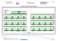
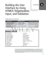
1. Open <strong>TDMS</strong> Logger.vi in the \Lab<strong>VI</strong>EW<br />
Basics II\<strong>TDMS</strong> Logger directory. This <strong>VI</strong> is pre-built for you as<br />
shown in Figure 1.<br />
2. Run the <strong>TDMS</strong> Logger <strong>VI</strong>.<br />
Figure 1. <strong>TDMS</strong> Logger Front Panel<br />
❑ Verify that the default value of the <strong>TDMS</strong> File Path control is<br />
\Lab<strong>VI</strong>EW Basics II\<strong>TDMS</strong> Logger\<br />
Test Data.tdms.<br />
❑ Enter your name in the Test Operator field.<br />
❑ Enter A001, A002, and A003 in the UUT Serial Numbers control.<br />
❑ Run and test the <strong>TDMS</strong> Logger <strong>VI</strong>. View the logged data in the<br />
<strong>TDMS</strong> File Viewer window. The graphs on the front panel of the<br />
<strong>TDMS</strong> Logger <strong>VI</strong> should also display a plot for each serial number<br />
you enter.<br />
❑ Click Quit to close the <strong>TDMS</strong> File Viewer window.<br />
© National Instruments Corporation 3 <strong>TDMS</strong> <strong>Reader</strong> <strong>VI</strong>
❑ Examine the block diagram.<br />
❑ Close the <strong>TDMS</strong> Logger <strong>VI</strong>. Do not save any changes.<br />
3. Create a blank <strong>VI</strong>.<br />
4. Save the <strong>VI</strong> as \Lab<strong>VI</strong>EW Basics II\<br />
<strong>TDMS</strong> <strong>Reader</strong>\<strong>TDMS</strong> <strong>Reader</strong>.vi.<br />
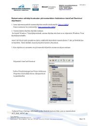
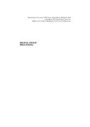
5. Build the <strong>VI</strong> front panel.<br />
Figure 2. <strong>TDMS</strong> <strong>Reader</strong> Front Panel<br />
❑ Create the <strong>TDMS</strong> File Path file path control with a default value of<br />
\Lab<strong>VI</strong>EW Basics II\<strong>TDMS</strong> Logger\<br />
Test Data.tdms.<br />
❑ Create the Serial Number string control.<br />
❑ Create the Time of Test time stamp indicator.<br />
❑ Create the Test Operator string indicator.<br />
❑ Create the Channel Data waveform graph.<br />
❑ Place a combo box control on the front panel. Label the combo box<br />
Data Set.<br />
❑ Right-click the Data Set control and select Edit Items from the<br />
shortcut menu.<br />
❑ Click Insert.<br />
❑ Enter Power Spectrum in the Items list.<br />
© National Instruments Corporation 4 <strong>TDMS</strong> <strong>Reader</strong> <strong>VI</strong>
❑ Click Insert.<br />
❑ Enter Time Data in the Items list.<br />
❑ Remove the checkmark from the Allow undefined values at run<br />
time box.<br />
❑ Click OK.<br />
❑ Select Time Data from the drop-down menu of the Data Set<br />
control.<br />
❑ Right-click the Data Set control and select Data Operations»<br />
Make Current Value Default from the shortcut menu.<br />
❑ Arrange the front panel as shown in Figure 2<br />
6. Open the <strong>TDMS</strong> file.<br />
❑ Add a <strong>TDMS</strong> Open function to the block diagram.<br />
❑ Right-click the operation input of the <strong>TDMS</strong> Open function and<br />
select Create»Constant from the shortcut menu.<br />
❑ Select open (read-only) as the value of the constant.<br />
Note Opening a file with the open (read-only) option increases the speed of reads in the<br />
file. Also, it does not lock the file so that other programs can use it at the same time.<br />
❑ Wire the <strong>TDMS</strong> File Path control to the file path input of the <strong>TDMS</strong><br />
Open function.<br />
7. Read the Author file property.<br />
❑ Add a <strong>TDMS</strong> Get Properties function to the block diagram.<br />
❑ Right-click the property name input of the <strong>TDMS</strong> Get Properties<br />
function and select Create»Constant from the shortcut menu.<br />
❑ Enter Author in the string constant.<br />
❑ Wire an empty string constant to the data type input of the <strong>TDMS</strong><br />
Get Properties function.<br />
❑ Wire the property value output of the <strong>TDMS</strong> Get Properties<br />
function to the Test Operator string indicator.<br />
© National Instruments Corporation 5 <strong>TDMS</strong> <strong>Reader</strong> <strong>VI</strong>
8. Read the Time Stamp file property.<br />
❑ Add a <strong>TDMS</strong> Get Properties function to the block diagram.<br />
❑ Right-click the property name input of the <strong>TDMS</strong> Get Properties<br />
function and select Create»Constant from the shortcut menu.<br />
❑ Enter Time Stamp in the string constant.<br />
❑ Wire a time stamp constant to the data type input of the <strong>TDMS</strong> Get<br />
Properties function.<br />
❑ Wire the property value output of the <strong>TDMS</strong> Get Properties<br />
function to the Time of Test indicator.<br />
9. Read the time data or power spectrum data for the specified UUT and<br />
display the data on the Channel Data waveform graph.<br />
❑ Add a <strong>TDMS</strong> Read function to the block diagram.<br />
❑ Wire the Data Set control to the group name in input of the <strong>TDMS</strong><br />
Read function.<br />
❑ Wire the Serial Number control to the channel name(s) in input of<br />
the <strong>TDMS</strong> Read function.<br />
❑ Wire the data output of the <strong>TDMS</strong> Read function to the Channel<br />
Data indicator.<br />
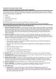
10. Close the file and handle errors.<br />
❑ Add a <strong>TDMS</strong> Close function to the block diagram.<br />
❑ Add a Simple Error Handler <strong>VI</strong> to the block diagram.<br />
❑ Wire the block diagram as shown in Figure 3.<br />
Figure 3. <strong>TDMS</strong> <strong>Reader</strong> Block Diagram<br />
© National Instruments Corporation 6 <strong>TDMS</strong> <strong>Reader</strong> <strong>VI</strong>
Test<br />
11. Save the <strong>VI</strong>.<br />
12. Set the attributes and time stamp properties of the waveform graph.<br />
❑ On the front panel, right-click the Channel Data graph and select<br />
Ignore Attributes.<br />
Note You must ignore the attributes of the waveform, otherwise the waveform name<br />
attribute would overwrite the labels you set. This option is available only after you wire<br />
a waveform to the graph.<br />
1. Read and display the time domain data.<br />
❑ On the <strong>VI</strong> front panel, ensure that the default <strong>TDMS</strong> File Path<br />
matches Table 1 and the Data Set is set to Time Data.<br />
❑ Enter A001 in the Serial Number control.<br />
Note A001 was one of the serial numbers you entered when you ran the <strong>TDMS</strong> Logger<br />
<strong>VI</strong>.<br />
❑ Run the <strong>VI</strong>. A sine wave should display in the Channel Data graph.<br />
❑ Change the Serial Number to A002.<br />
❑ Run the <strong>VI</strong>. A different sine wave should display.<br />
2. Read and display the power spectrum data.<br />
❑ Change the Data Set control to Power Spectrum.<br />
❑ Run the <strong>VI</strong>. Power spectrum data should display in the Channel Data<br />
graph.<br />
3. Close the <strong>VI</strong>.<br />
End of Exercise<br />
© National Instruments Corporation 7 <strong>TDMS</strong> <strong>Reader</strong> <strong>VI</strong>