MVME5500 Series VME Single-Board Computer data sheet
MVME5500 Series VME Single-Board Computer data sheet
MVME5500 Series VME Single-Board Computer data sheet

You also want an ePaper? Increase the reach of your titles
YUMPU automatically turns print PDFs into web optimized ePapers that Google loves.
Data<strong>sheet</strong><br />
<strong>M<strong>VME</strong>5500</strong> <strong>Series</strong><br />
<strong>VME</strong> <strong>Single</strong>-<strong>Board</strong><br />
<strong>Computer</strong><br />
■ MPC7455 processor at speeds of 1 GHz and beyond<br />
■ 256KB of on-chip L2 cache and 2MB of L3 cache<br />
■ AltiVec coprocessor for high-performance<br />
computational applications<br />
■ 512MB of on-board SDRAM ECC memory and 512MB<br />
additional memory via a memory mezzanine card for<br />
a total of 1GB of memory<br />
■ 40MB Flash memory (32MB soldered and 8MB in<br />
sockets)<br />
■ Dual PCI buses and dual PMC sites with a bus speed<br />
of up to 66 MHz<br />
■ Gigabit Ethernet interface and a 10/100BaseTX<br />
Ethernet interface<br />
■ 64-bit PCI expansion mezzanine connector allowing<br />
up to four more PMCs<br />
■ I/O compatibility with M<strong>VME</strong>51xx family<br />
■ <strong>Single</strong> <strong>VME</strong> slot even when fully configured with two<br />
PMC modules or one PMC module and an add-on<br />
memory mezzanine<br />
Motorola’s highest performance <strong>VME</strong>bus single-board computer<br />
The <strong>M<strong>VME</strong>5500</strong> is the latest flagship of the Motorola <strong>VME</strong> product line, enabling even<br />
higher levels of performance in a single <strong>VME</strong>bus slot. The <strong>M<strong>VME</strong>5500</strong> utilizes the<br />
latest MPC7455 processor running at speeds of 1 GHz and beyond, which is ideal for<br />
<strong>data</strong> intensive applications.<br />
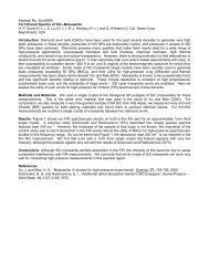
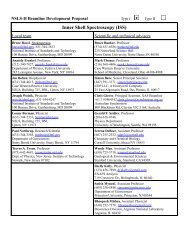
The <strong>M<strong>VME</strong>5500</strong> provides more than just faster processor performance; it provides<br />
balanced performance from the processor, memory, local buses, and I/O subsystems.<br />
The powerful Marvell Discovery system controller, with support for a 133 MHz host bus<br />
and a 133 MHz SDRAM memory bus, is well matched to the high-speed processor. To<br />
match the system I/O to the outstanding processor performance, the <strong>M<strong>VME</strong>5500</strong><br />
provides dual 64-bit, 33/66 MHz PCI buses. Each PCI bus has a PMC site supporting<br />
cards running at 33 or 66 MHz. The Universe II <strong>VME</strong> interface and PMCspan connector<br />
are isolated from the PMC sites on a dedicated 33 MHz PCI bus segment, so that both<br />
PMC sites are capable of 66 MHz operation. The <strong>M<strong>VME</strong>5500</strong> also offers a Gigabit<br />
Ethernet interface, a 10/100BaseTX Ethernet interface, and two serial ports. All of this<br />
adds up to a set of well-balanced, high-performance subsystems for unparalleled<br />
performance.<br />
The <strong>M<strong>VME</strong>5500</strong> series is designed to meet the needs of OEMs servicing the defense<br />
and aerospace, industrial automation, and medical imaging market segments.<br />
Customers looking for a "technology refresh" for their application while maintaining<br />
backward compatibility with their existing <strong>VME</strong>bus infrastructure can upgrade to the<br />
<strong>M<strong>VME</strong>5500</strong> series and take advantage of the enhanced performance features.<br />
L3 Cache<br />
2MB<br />
MPC7455<br />
1+ GHz<br />
Ethernet<br />
10/100BaseTX<br />
PHY<br />
Port 2<br />
10/100BaseTX<br />
FP I/O<br />
Port 1<br />
10/100/1000BaseTX<br />
FP I/O<br />
SDRAM<br />
Mezzanine<br />
512MB<br />
SDRAM<br />
133 MHz<br />
512MB<br />
PMC<br />
Slot 2<br />
COM1 COM2<br />
FP I/O Header<br />
EIA232<br />
UART<br />
IPMC<br />
Slot 1<br />
PMC FP I/O PMC FP I/O<br />
P2<br />
EIA232<br />
UART<br />
Battery Flash<br />
NVRAM<br />
RTC<br />
P1<br />
32MB<br />
(soldered)<br />
8MB<br />
(sockets)<br />
A32/D64-bit, 133 MHz PCI Bridge &<br />
Memory Controller<br />
66 MHz PCI Local Bus — A32/D64-bit<br />
Discovery<br />
PCI<br />
Gigabit<br />
Bridge<br />
Ethernet 66 MHz PCI Local Bus<br />
Controller<br />
— A32/D64-bit<br />
33 MHz PCI Local Bus<br />
— A32/D64-bit<br />
Universe II<br />
PMCspan<br />
Connector
2 <strong>M<strong>VME</strong>5500</strong> <strong>Series</strong><br />
<strong>M<strong>VME</strong>5500</strong> <strong>Series</strong> Details<br />
<strong>M<strong>VME</strong>5500</strong> SERIES DETAILS<br />
Backward Compatibility The <strong>M<strong>VME</strong>5500</strong> continues the direction that Motorola started with the M<strong>VME</strong>5100 series of providing a migration<br />
path from Motorola’s embedded controllers and single-board computers (SBCs) to a single platform. This migration<br />
path enables OEMs to support varying I/O requirements with the same base platform, simplifying part number<br />
maintenance, technical expertise requirements, and sparing.<br />
The <strong>M<strong>VME</strong>5500</strong> series offers customers a migration path from the M<strong>VME</strong>2300, M<strong>VME</strong>2400, M<strong>VME</strong>2600,<br />
M<strong>VME</strong>2700, and M<strong>VME</strong>5100 boards to allow them to take advantage of features such as the MPC7455 processor,<br />
Gigabit Ethernet, and 33/66 MHz PMC sites.<br />
P2 I/O Modes<br />
Like the M<strong>VME</strong>5100 series, the <strong>M<strong>VME</strong>5500</strong> series supports two, jumper-configurable P2 I/O modes: PMC mode and<br />
IPMC mode. PMC mode is backward compatible with the M<strong>VME</strong>2300/M<strong>VME</strong>2400 and M<strong>VME</strong>5100 in PMC mode. In<br />
PMC mode, 64 pins from PMC Slot 1 and 46 pins from PMC Slot 2 are available on P2 for PMC rear I/O. In IPMC<br />
mode, the <strong>M<strong>VME</strong>5500</strong> series supports legacy M<strong>VME</strong>761 or M<strong>VME</strong>712M I/O modules (with limited PMC I/O) when<br />
an IPMC761 or IPMC712 PMC card is populated in PMC Slot 1. In this configuration, PMC Slot 2 contains some<br />
signals that are reserved for extended SCSI.<br />
IPMC Modules<br />
The IPMC761 and IPMC712 are optional add-on PMC modules that provide backward compatibility with previous<br />
generation Motorola products (such as M<strong>VME</strong>2600, M<strong>VME</strong>2700, and M<strong>VME</strong>5100 in IPMC mode) using the<br />
M<strong>VME</strong>761 or M<strong>VME</strong>712M transition module. IPMC modules provide rear I/O support for the following:<br />
• One single-ended Ultra Wide SCSI port<br />
• One parallel port<br />
• Four serial ports (two or three async and one or two sync/async, depending on module)<br />
With this PMC card configuration, one PMC slot is still available, providing support for OEM product customization.<br />
Transition Modules<br />
M<strong>VME</strong>761<br />
The M<strong>VME</strong>761 transition module provides industry-standard connector access to the IEEE 1284 parallel port, a<br />
10BaseT or 100BaseT port via an RJ-45 connector, two DB-9 connectors providing access to the asynchronous serial<br />
ports configured as EIA-574 DTE, and two HD-26 connectors providing access to the sync/async serial ports. These<br />
serial ports, labeled as Serial 3 and Serial 4 on the faceplate of the M<strong>VME</strong>761, are individually user-configurable as<br />
EIA-232, EIA-530, V.35, or X.21 DCE or DTE via the installation of Motorola serial interface modules (SIMs).<br />
A P2 adapter provides interface module signals to the M<strong>VME</strong>761 transition module. The 3-row P2 adapter can be<br />
used for 8-bit SCSI. A 5-row P2 adapter supports 16-bit SCSI and PMC I/O.<br />
M<strong>VME</strong>712M<br />
The M<strong>VME</strong>712M transition module provides industry-standard connector access to the Centronics parallel port, a<br />
narrow SCSI port, and four DB-25 connectors providing access to the asynchronous/synchronous serial ports jumper<br />
configurable as EIA-232 DCE or DTE. A P2 adapter provides interface signals to the M<strong>VME</strong>712M transition module.<br />
The 3-row P2 adapter can be used for 8-bit SCSI.<br />
To gain access to the additional user-definable I/O pins provided via the 5-row <strong>VME</strong>64 extension connector, a special<br />
P2 adapter board is available. This adapter panel replaces the traditional 3-row P2 adapter and extends its capability<br />
by providing access to the PMC I/O pins.
Software Support Firmware Monitor<br />
Firmware must fulfill the traditional functions of power-on self-test (POST), initialization, and operating system<br />
booting. Motorola’s innovative firmware (known as MotLoad) that is resident on the <strong>M<strong>VME</strong>5500</strong> exceeds these<br />
requirements with expanded features such as interrupt driven I/O, more comprehensive power-up tests, and<br />
extensive diagnostics with new scripting capability. And of course, MotLoad provides a debugger interface similar to<br />
the time proven "BUG" interface on previous <strong>VME</strong>bus boards from Motorola.<br />
Operating Systems and Kernels<br />
WindRiver Systems VxWorks and MontaVista Linux Professional Edition will be available for the <strong>M<strong>VME</strong>5500</strong>.<br />
Libraries<br />
VSI/Pro VSIPL libraries from MPI Software Technology will be available on the <strong>M<strong>VME</strong>5500</strong>.<br />
Built-In Test Software<br />
Motorola Built-In Test (MBIT) software is available for use on the <strong>M<strong>VME</strong>5500</strong> series. MBIT is an off-the-shelf<br />
software infrastructure designed to verify correct operation of Motorola hardware and enable the incorporation of<br />
system-level diagnostics. Two versions of MBIT, board-level and system-level, are available and are compatible with<br />
WindRiver Systems Tornado 2.1.<br />
The board-level MBIT is a comprehensive diagnostic software package designed to verify the performance of boardmounted<br />
logic devices. All tests can execute at boot-up, while selected tests can run continuously in the background<br />
of user applications. An application programming interface (API) is included to provide access to test results and to<br />
modify and control the operation of device tests. A comprehensive user’s manual is available.<br />
The system-level MBIT includes all functionality and API function calls of the board-level version and enables<br />
system-wide testing. The system-level MBIT provides a framework and additional API function calls to support the<br />
inclusion of software designed to test custom hardware and/or system components. A comprehensive user’s manual<br />
with software development guidelines is available.<br />
Processor<br />
Microprocessor: MPC7455<br />
Clock Frequency: 1 GHz<br />
On-chip L1 Cache (I/D): 32KB/32KB<br />
On-chip L2 Cache (I/D): 256KB/256KB<br />
L3 Cache: 2MB<br />
System Controller<br />
Marvell Discovery GT-64260A<br />
Main Memory<br />
Specifications<br />
SPECIFICATIONS<br />
Type: PC133 ECC SDRAM<br />
Speed: 133 MHz<br />
Capacity: 512MB on-board, expandable to 1GB with<br />
add-on memory mezzanine card. If a PMC<br />
module is plugged into PMC Slot 1, the<br />
memory mezzanine card cannot be used<br />
because the PMC module covers the<br />
memory mezzanine connector.<br />
Configurations: 512MB in two banks<br />
Flash Memory<br />
NVRAM<br />
Type: EEPROM, on-board programmable<br />
Capacity: 8MB via two 56-pin TSOP sockets; 32MB<br />
soldered Flash<br />
Write Protection: 32MB of surface-mount Flash is writeprotectable<br />
via jumper<br />
Capacity: 32KB (4KB available for users)<br />
Cell Storage Life: 50 years at 55° C<br />
Cell Capacity Life: 5 years at 100% duty cycle, 25° C<br />
Removable Battery: Yes<br />
Counters/Timers<br />
TOD Clock Device: M48T37V<br />
Real-Time<br />
Timers/Counters:<br />
Eight, 32-bit programmable<br />
Watchdog Timer: Time-out generates reset<br />
<strong>M<strong>VME</strong>5500</strong> <strong>Series</strong> 3
4 <strong>M<strong>VME</strong>5500</strong> <strong>Series</strong><br />
<strong>VME</strong>bus Interface: ANSI/VITA 1-1994 <strong>VME</strong>64 (IEEE STD<br />
1014)<br />
Ethernet Interfaces<br />
Asynchronous Serial Ports<br />
IPMC Modules PMC Interface<br />
Controller: Tundra Universe II<br />
DTB Master: A16-A32; D08-D64, SCT, BLT<br />
DTB Slave: A24-A32; D08-D64, BLT, UAT<br />
Arbiter: RR/PRI<br />
Interrupt<br />
Handler/Generator:<br />
IRQ 1-7/Any one of seven IRQs<br />
System Controller: Yes, jumperable or auto detect<br />
Location Monitor: Two, LMA32<br />
Port 1<br />
Controller: Intel 82544EI Gigabit Ethernet controller<br />
Interface Speed: 10/100/1000Mb/s<br />
Connector: Routed to front panel RJ-45<br />
Port 2<br />
Controller: Controller integrated into GT-64260A<br />
system controller<br />
Interface Speed: 10/100Mb/s<br />
Connector: Routed to front panel RJ-45 or optionally<br />
routed to P2, RJ-45 on M<strong>VME</strong>761<br />
Controller: Two TL16C550C UARTs<br />
Number of Ports: Two, 16550 compatible<br />
Async Baud Rate, bps<br />
max.:<br />
38.4K EIA-232, 115Kb/s raw<br />
Connector: Routed to front panel RJ-45; one on planar<br />
for development use<br />
SCSI Bus<br />
Address/Data: A32/D32/D64, PMC PN1, PN2, PN3, PN4<br />
connectors<br />
PCI Bus Clock: 33 MHz<br />
Signaling: 5V<br />
Module Type: Basic single-wide; P2 I/O<br />
Controller: Symbios 53C895A<br />
PCI Local Bus DMA: Yes, with PCI local bus burst<br />
Asynchronous (8-bit 5.0MB/s<br />
mode):<br />
Ultra SCSI: 20.0MB/s (8-bit mode), 40.0MB/s (16-bit<br />
mode)<br />
Note: 16-bit SCSI operation precludes the use of some PMC Slot 2<br />
signals.<br />
Dual IEEE P1386.1 PCI Mezzanine Card Slots<br />
Address/Data: A32/D32/D64, PMC PN1, PN2, PN3, PN4<br />
connectors<br />
PCI Bus Clock: 33/66 MHz<br />
Signaling: 3.3V or 5V, configurable with keying pin<br />
Power: +3.3V, +5V, ±12V<br />
Module Types: Two single-wide or one double-wide, front<br />
panel or P2 I/O, PMC and PrPMC support<br />
Note: If a PMC module is plugged in PMC Slot 1, the memory<br />
mezzanine card cannot be used because the PMC module covers the<br />
memory mezzanine connector.<br />
PCI Expansion Connector<br />
Power Requirements<br />
(Not including power required by PMC or IMPC modules)<br />
+5V ± 5% +12V ± 10% –12V ± 10%<br />
<strong>Board</strong> Size<br />
Address/Data: A32/D32/D64<br />
PCI Bus Clock: 33 MHz<br />
Signaling: 5V<br />
Power: +3.3V, +5V, ±12V<br />
Connector: 114-pin connector located on <strong>M<strong>VME</strong>5500</strong><br />
planar, same location as on M<strong>VME</strong>5100<br />
planar<br />
<strong>M<strong>VME</strong>5500</strong>: TBD TBD TBD<br />
<strong>M<strong>VME</strong>5500</strong><br />
with M<strong>VME</strong>761:<br />
TBD TBD TBD<br />
Height: 233.4 mm (9.2 in.)<br />
Depth: 160.0 mm (6.3 in.)<br />
Front Panel Height: 261.8 mm (10.3 in.)<br />
Width: 19.8 mm (0.8 in.)<br />
Max. Component<br />
Height:<br />
14.8 mm (0.58 in.)<br />
Synchronous Serial Ports<br />
Controller: 85230/8536<br />
Number of Ports: Two (IPMC761); one (IPMC712)<br />
Configuration: IPMC761: TTL to P2 (both ports), SIM<br />
configurable on M<strong>VME</strong>761;<br />
IPMC712: EIA-232 to P2<br />
Baud Rate, bps max.: 2.5M sync, 38.4K async<br />
Oscillator Clock Rate<br />
(PCLK):<br />
10 MHz/5 MHz<br />
Asynchronous Serial Ports<br />
Controller: 16C550 UART; 85230/8536<br />
Number of Ports: Two (IPMC761); three (IPMC712)<br />
Configuration: EIA-574 DTE (IPMC761);<br />
EIA-232 (IPMC712)<br />
Async Baud Rate, bps<br />
max.:<br />
38.4K EIA-232, 115Kb/s raw
Transition Modules I/O Connectors<br />
Parallel Port Power Requirements<br />
<strong>Board</strong> Size<br />
All Modules Environmental<br />
Safety<br />
Controller: PC97307<br />
Configuration: 8-bit bi-directional, full IEEE 1284 support;<br />
Centronics compatible (minus EPP and<br />
ECP on M<strong>VME</strong>712M)<br />
Modes: Master only<br />
All printed wiring boards (PWBs) are manufactured with a flammability<br />
rating of 94V-0 by UL recognized manufacturers.<br />
(Additional power load placed on <strong>M<strong>VME</strong>5500</strong> with IPMC installed)<br />
IPMC761 IPMC712<br />
+5V: 0.5 A max. 0.5 A max.<br />
+3.3V: 0.75 A max. 0.75 A max.<br />
M<strong>VME</strong>761 M<strong>VME</strong>712M<br />
Asynchronous Serial Ports: Two, DB-9 labeled as COM1 and COM2 Three, DB-25 labeled as Serial 1, Serial 2, and Serial 3<br />
Synchronous Serial Ports: Two HD-26 labeled as Serial 3 and Serial 4 (userconfigurable<br />
via installation of SIMs),<br />
Two 60-pin connectors on M<strong>VME</strong>761 planar for<br />
installation of two SIMs<br />
One, DB-25 labeled as Serial 4<br />
Parallel Port: HD-36, Centronics compatible D-36, Centronics compatible<br />
Ethernet: 10BaseT or 100BaseT, RJ-45 NA<br />
SCSI: 8- or 16-bit, 50- or 68-pin connector via P2 adapter 8-bit, standard SCSI D-50<br />
Height: 233.4 mm (9.2 in.)<br />
Depth: 80.0 mm (3.1 in.)<br />
Front Panel Height: 261.8 mm (10.3 in.)<br />
Front Panel Width: M<strong>VME</strong>761: 19.8 mm (0.8 in.)<br />
M<strong>VME</strong>712M: 39.6 mm (1.6 in.)<br />
Temperature: 0° C to +55° C<br />
(inlet air temp.<br />
w/forced air cooling)<br />
Vibration: 2 Gs RMS,<br />
20-2000 Hz random<br />
Operating Non-operating<br />
–40° C to +85° C<br />
1 G sinusoidal,<br />
5–100 Hz<br />
2 axes<br />
Electromagnetic Compatibility (EMC)<br />
Intended for use in systems meeting the following regulations:<br />
U.S.: FCC Part 15, Subpart B, Class A (non-residential)<br />
Canada: ICES-003, Class A (non-residential)<br />
Motorola <strong>Computer</strong> Group board products are tested in a<br />
representative system to the following standards, results pending for<br />
configurations with IPMC712:<br />
CE Mark per European EMC Directive 89/336/EEC with<br />
Amendments; Emissions: EN55022 Class A; Immunity: EN55024<br />
<strong>M<strong>VME</strong>5500</strong> <strong>Series</strong> 5
Motorola <strong>Computer</strong> Group<br />
Regional Offices<br />
Ordering Information<br />
ORDERING INFORMATION<br />
Part Number Description<br />
<strong>M<strong>VME</strong>5500</strong>-0161 1 GHz MPC7455 processor, 512MB SDRAM, Scanbe handles<br />
<strong>M<strong>VME</strong>5500</strong>-0163 1 GHz MPC7455 processor, 512MB SDRAM, IEEE handles<br />
Memory<br />
RAM5500-007 512MB memory mezzanine expansion card<br />
Once released, documentation is available for online viewing and ordering at http://www.motorola.com/computer/literature<br />
General availability of the <strong>M<strong>VME</strong>5500</strong> series is scheduled for March 2003.<br />
NORTH AMERICA: Tempe, AZ 800-759-1107 or 602-438-5720<br />
EUROPE: Loughborough, UK +44 1509 634300<br />
EAST MEDITERRANEAN: Tel Aviv, Israel +972 3 568 4388<br />
ASIA: Shanghai, China +86 21 5292 5693<br />
PACIFIC RIM: Tokyo, Japan +81 3 5424 3101<br />
ASIA/PACIFIC: Hong Kong +852 2966 3210<br />
www.motorola.com/computer<br />
MOTOROLA and the Stylized M Logo are registered in the U.S. Patent and Trademark Office. All other product or<br />
service names are the property of their respective owners.<br />
© Motorola Inc. 2002<br />
This <strong>data</strong><strong>sheet</strong> identifies products, their specifications, and their characteristics, which may be suitable for certain<br />
applications. It does not constitute an offer to sell or a commitment of present or future availability, and should not be<br />
relied upon to state the terms and conditions, including warranties and disclaimers thereof, on which Motorola may<br />
sell products. A prospective buyer should exercise its own independent judgement to confirm the suitability of the<br />
products for particular applications. Motorola reserves the right to make changes, without notice, to any products or<br />
information herein which will, in its sole discretion, improve reliability, function, or design. Motorola does not assume<br />
any liability arising out of the application or use of any product or circuit described herein; neither does it convey any<br />
license under its patent or other intellectual property rights or under others. This disclaimer extends to any prospective<br />
buyer, and it includes Motorola's licensee, licensee's transferees, and licensee's customers and users. Availability of<br />
some of the products and services described herein may be restricted in some locations.<br />
M5500-D1 9/02