SV-200 - WEST. Elektronik GmbH
SV-200 - WEST. Elektronik GmbH
SV-200 - WEST. Elektronik GmbH

You also want an ePaper? Increase the reach of your titles
YUMPU automatically turns print PDFs into web optimized ePapers that Google loves.
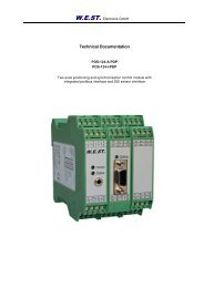
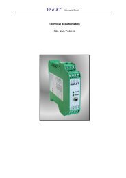
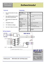
Product information<br />
Pin out<br />
<strong>SV</strong> <strong>200</strong><br />
Characteristics<br />
• Dynamic servo valve control<br />
• Dither- and offset adjustment<br />
• Covered potentiometer<br />
(optional: front side)<br />
• Maximum current: 10...<strong>200</strong> mA,<br />
adjustable via DIL-switches in<br />
steps to 10 mA<br />
• Auxiliary supply: positive and<br />
negative<br />
• Optional up to 300 mA<br />
• Inexpensive snap-on housing<br />
• Replaced <strong>SV</strong>-60<br />
Spannungsversorgung<br />
Power supply<br />
24 V<br />
18..30V<br />
0V<br />
Eingang (+/-10V)<br />
Input (+/-10V)<br />
0 V<br />
3<br />
4<br />
11<br />
9<br />
10<br />
DC<br />
Ordering code: <strong>SV</strong>-<strong>200</strong>-21<br />
+<br />
-<br />
Servo Valve Power Amplifier<br />
DC<br />
+<br />
S5 S4 S3 S2 S1<br />
off off off off on 10 mA<br />
off off off on off 20 mA<br />
off off off on on 30 mA<br />
off off on off off 40 mA<br />
off off on off on 50 mA<br />
off off on on off 60 mA<br />
off off on on on 70 mA<br />
off on off off off 80 mA<br />
off on off off on 90 mA<br />
off on off on off 100 mA<br />
Technical Data<br />
Power supply<br />
Current consumption<br />
Output<br />
max. current<br />
max resistance for<br />
max current<br />
Input signal<br />
Barrier frequency<br />
[V]<br />
[A]<br />
[A]<br />
[OHM]<br />
[V]<br />
[Hz]<br />
Dither [Hz]<br />
[%]<br />
18..30<br />
0,3<br />
Offset [%] ±10<br />
Auxiliary supply [V] [mA] ±10, 10<br />
0,01 to 0,2<br />
via DIL switches internal adjustable<br />
33<br />
±10 (100 kOhm)<br />
140<br />
250 / 100 (to select)<br />
0..15 (5% pre-adjusted)<br />
Housing Snap-On Module EN 50022<br />
Temperature range °C 0..50<br />
Dimension [mm] H=120 ,L=100, T=23<br />
Connections 4 x 4pol. Screw Terminals<br />
EMC<br />
<strong>SV</strong>-<strong>200</strong><br />
Offset Dither<br />
-<br />
S5 S4 S3 S2 S1<br />
off on off on on 110 mA<br />
off on on off off 120 mA<br />
off on on off on 130 mA<br />
off on on on off 140 mA<br />
off on on on on 150 mA<br />
on off off off off 160 mA<br />
on off off off on 170 mA<br />
on off off on off 180 mA<br />
on off off on on 190 mA<br />
on off on off off <strong>200</strong> mA<br />
Vref-neg<br />
Vref-pos<br />
Leistungsstufe /<br />
Power stage<br />
S1<br />
S2<br />
S3<br />
S4<br />
S5<br />
S6<br />
S6 Dither<br />
on<br />
off<br />
250 Hz<br />
100 Hz<br />
5<br />
6<br />
7<br />
8<br />
GND<br />
15<br />
16<br />
GND<br />
EN 50082-2<br />
EN 50081-1<br />
Servoventil /<br />
Servovalve<br />
Potentiometer<br />
Offset<br />
Dither<br />
LED<br />
W.E.ST. W.E.ST.<br />
<strong>Elektronik</strong> <strong>GmbH</strong><br />
Poststraße 26<br />
D-41372 Niederkrüchten<br />
Telefon: 0 21 63 / 577355 0<br />
Fax: 0 21 63 / 577355 11<br />
E-Mail: info@w-e-st.de<br />
Homepage: www.w-e-st.de
<strong>SV</strong> <strong>200</strong> Installation) 2<br />
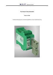
Typical wiring (<strong>SV</strong>-<strong>200</strong>-20)<br />
5<br />
13<br />
6<br />
10<br />
14<br />
7<br />
11<br />
8<br />
12<br />
0V<br />
15 16<br />
Analoger Sollwert (+/-10V)<br />
Analogue command signal (+/-10V)<br />
output current<br />
Schirm /<br />
Screen<br />
PE<br />
1<br />
9<br />
2<br />
3<br />
4<br />
Spannungsversorgung<br />
Power Supply<br />
PE<br />
Schirm /<br />
Screen<br />
Servoventil /<br />
Servo valve<br />
Output characteristic (<strong>SV</strong>-<strong>200</strong>-20)<br />
0,20<br />
0,18<br />
0,16<br />
0,14<br />
0,12<br />
0,10<br />
0,08<br />
0,06<br />
0,04<br />
0,02<br />
Operating range current vs. resistance<br />
24V<br />
0V<br />
0,00<br />
0,00 100,00 <strong>200</strong>,00 300,00 400,00 500,00 600,00<br />
max resistance<br />
Wiring guidelines:<br />
• Relays and solenoids operating from the same power<br />
supply have to be damped by surge protection elements.<br />
• Screened wiring of analogue signals are mandatory.<br />
• Do not install this unit in areas with high EMI (i.e. motor<br />
cables, AC/DC commutator motors, frequency<br />
converters....).<br />
Start up:<br />
• Adjusting of maximum current via internal DILswitches.<br />
Attention: valve solenoids can be<br />
damaged by high current.<br />
• Offset (zero point) adjustment . This module is<br />
pre-adjusted, often no further adjustment is necessary.<br />
• Dither adjustment. The Dither amplitude have to<br />
be optimised to get best valve or drive performance.<br />
Dither adjustment will reduce hysteresis.<br />
The output characteristic describes maximally drivable output current associated at the load resistance<br />
output voltage<br />
8<br />
7<br />
6<br />
5<br />
4<br />
3<br />
2<br />
1<br />
0<br />
Operating range voltage vs. Resistance I =<br />
const <strong>200</strong>mA<br />
0,00 5,00 10,00 15,00 20,00 25,00 30,00 35,00 40,00<br />
max resistance