

Manual Flushometers Section | Maintenance Guide - Sloan Valve ...
Manual Flushometers Section | Maintenance Guide - Sloan Valve ...
Manual Flushometers Section | Maintenance Guide - Sloan Valve ...

Create successful ePaper yourself
Turn your PDF publications into a flip-book with our unique Google optimized e-Paper software.
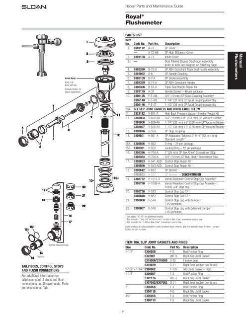
Tailpiece<br />
Control Stop and Caps<br />
TAILPIECES, CONTROL STOPS<br />
AND FLUSH CONNECTIONS<br />
For additional information on<br />
tailpieces, control stops and flush<br />
connections see Showerheads, Parts<br />
and Accessories Tab.<br />
<strong>Valve</strong> Body<br />
Body only<br />
Body with tail<br />
Consuly factory for<br />
proper application<br />
11<br />
Repair Parts and <strong>Maintenance</strong> <strong>Guide</strong><br />
Royal ®<br />
Flushometer<br />
PARTS LIST<br />
Item<br />
No. Code No. Part No. Description<br />
1. 0301172 A-72 CP Cover<br />
— A-72-HE CP High Efficiency Cover<br />
2. 0301168 A-71 Inside Cover<br />
3. — Dual Filtered Bypass Diaphragm Assembly<br />
(refer to table and diagram on following page)<br />
4. 0302390 B-73-A CP ADA-Compliant Triple Seal Handle Assembly<br />
5. 0301082 A-6 CP Handle Coupling<br />
6. 0302109 B-7-A CP Socket Assembly<br />
7. 0302389 B-74-A CP ADA-Compliant Handle<br />
8. 3302306 B-51-A Triple Seal Handle Repair Kit<br />
9. 5301139 A-31 Handle Gasket – 48 per package<br />
10. 0306125 F-5-AW 3/4” (19 mm) CP Spud Coupling Assembly<br />
0306140 F-5-AU 1-1/4” (32 mm) CP Spud Coupling Assembly<br />
0306146 F-5-AT 1-1/2” (38 mm) CP Spud Coupling Assembly<br />
10A. SEE SLIP JOINT GASKETS AND RINGS TABLE BELOW<br />
11. 3323182 V-651-A High Back Pressure Vacuum Breaker Repair Kit<br />
12. 3393004 V-600-AA 3/4” (19 mm) x 9” (228 mm) CP Vacuum Breaker<br />
3393006 V-600-AA 1-1/4” (32 mm) x 9” (228 mm) CP Vacuum Breaker<br />
3393007 V-600-AA 1-1/2” (38 mm) x 9” (228 mm) CP Vacuum Breaker<br />
13. 0308676 H-550 CP Stop Coupling<br />
14. 0308801 H-551-A CP Adjustable Tailpiece 2-1/16” (52 mm long)<br />
Standard Length*<br />
15A. 5308696 H-553 O-ring – 24 per package<br />
15B. 5308381 H-552 Locking Ring – 12 per package<br />
16. 3308386 H-700-A 1” (25 mm) CP Bak-Chek ® Screwdriver Stop<br />
3308384 H-700-A 3/4” (19 mm) CP Bak-Chek ® Screwdriver Stop<br />
17. 3308853 H-541-ASD Control Stop Repair Kit †<br />
3308856 H-543-ASD Control Stop Repair Kit ‡<br />
18. 0308612 H-622 CP Bonnet †<br />
0308843 H-577 CP Bonnet ‡ – DISCONTINUED<br />
19. 3308772 H-1010-A Vandal Resistant Control Stop Cap Assembly †<br />
3308790 H-1009-A Vandal Resistant Control Stop Cap Assembly ‡<br />
H-600 3/4” Stop only<br />
20. 0308738 H-573 Control Stop Cap CP †<br />
0308848 H-582 Control Stop Cap CP ‡<br />
21. 3308866 H-574 Control Stop Cap with Bumper †<br />
(–YO Variation)<br />
22. 3308867 H-576 Control Stop Cap with Extended Bumper †<br />
(–YG Variation)<br />
* See pages 100-101 for additional lengths<br />
† For use with 1” and 3/4” H-700-A and 1” H-600-A Bak-Chek ® screwdriver control stop<br />
‡ For use with 3/4" H-600-A Bak-Chek ® screwdriver control stop<br />
<strong>Sloan</strong> products are also available in satin, brushed nickel, chrome, gold and polished brass finishes – contact<br />
factory for part numbers.<br />
ITEM 10A. SLIP JOINT GASKETS AND RINGS<br />
Size Code No. Part No. Description<br />
1-1/2” 5306058 F-3 Red Friction Ring<br />
5322001 VBF-5 Black Slip Joint Gasket<br />
0319086/5319086 S-30 Flexible Seat<br />
0319079 S-21 Rigid Seat (rubber over brass)<br />
1-1/2” x 1-1/4” 0396062 F-105 Slip Joint Gasket – Rigid<br />
1-1/4” 5306057 F-3 Red Friction Ring<br />
5322176 VBF-5 Black Slip Joint Gasket<br />
0307052/5307052 G-21 Rigid Seat (rubber over brass)<br />
1” 5306056 F-3 Red Friction Ring<br />
5306115 F-5 Black Slip Joint Gasket<br />
3/4” 5306055 F-3 Red Friction Ring<br />
5306113 F-5 Black Slip Joint Gasket<br />
<strong>Manual</strong><br />
<strong>Flushometers</strong>
<strong>Manual</strong><br />
<strong>Flushometers</strong><br />
DUAL FILTERED DIAPHRAGM ASSEMBLY<br />
Available in diaphragm only and Royal ® Performance Kits.<br />
Royal ® Performance Kit includes dual filtered diaphragm assembly (item 3),<br />
handle repair kit with triple seal packing (item 8), high back pressure<br />
vacuum breaker repair kit (item 11), and one tailpiece O-ring (item 15A).<br />
DIAPHRAGM ONLY KIT contains “drop-in” dual filtered diaphragm assembly<br />
(item 3) ONLY.<br />
The dual filtered diaphragm can be used in Royal, ® Regal, ® and similar<br />
diaphragm-style valve bodies. For use in <strong>Sloan</strong> valve bodies with a bellshaped<br />
cover (manufactured before 1964), replace the bottom filter ring in<br />
these kits with a blue A-108 filter ring (not shown <strong>Sloan</strong> Code No. 5301283).<br />
NOTE: In January 1998, the Royal ® diaphragm design was upgraded to a<br />
preassembled unit with two (2) plastic filtering rings attached to the rubber diaphragm<br />
(one on top and one on bottom). If the flushometer you are servicing has our older,<br />
segmented diaphragm with brass by-pass hole, refer to our Regal section for<br />
additional troubleshooting information.<br />
The colors of the relief valve and<br />
the refill head plus the shape of<br />
flow ring identify the flush volume<br />
of a DUAL FILTERED DIAPHRAGM<br />
ASSEMBLY.<br />
12<br />
Repair Parts and <strong>Maintenance</strong> <strong>Guide</strong><br />
Royal ®<br />
Flushometer<br />
ROYAL ® PERFORMANCE KIT<br />
Relief Refill Flow<br />
Code No. Part No. Description <strong>Valve</strong> † Head* Ring<br />
3301070 A-1101-A Low Consumption Water Closets-1.6 gpf (6.0 Lpf)** Green Gray Smooth<br />
3301071 A-1102-A Water Saver Water Closets-3.5 gpf (13.2 Lpf)** White Gray Smooth<br />
3301072 A-1103-A 9 Liter European Water Closets-2.4 gpf (9.0 Lpf) Blue Gray Smooth<br />
3301073 A-1106-A Wash Down Urinals-0.5 gpf (1.9 Lpf) Green Black Smooth<br />
3301074 A-1107-A Low Consumption Urinals-1.0 gpf (3.8 Lpf)** Green Black Slotted<br />
3301075 A-1108-A Water Saver Urinals-1.5 gpf (5.7 Lpf)** Black Black Smooth<br />
*Closet refill heads (gray) have larger slots than urinal refill heads (black).<br />
DIAPHRAGM ONLY KIT<br />
Relief Refill Flow<br />
Code No. Part No. Description <strong>Valve</strong> † Head* Ring<br />
3301502 A-1041-A Low Consumption Water Closets-1.6 gpf (6.0 Lpf)** Green Gray Smooth<br />
3301501 A-1038-A Water Saver Water Closets-3.5 gpf (13.2 Lpf)** White Gray Smooth<br />
3301505 A-1044-A 9 Liter European Water Closets-2.4 gpf (9.0 Lpf) Blue Gray Smooth<br />
3301504 A-1043-A Wash Down Urinals-0.5 gpf (1.9 Lpf) Green Black Smooth<br />
3301503 A-1042-A Low Consumption Urinals-1.0 gpf (3.8 Lpf)** Green Black Slotted<br />
3301500 A-1037-A Water Saver Urinals-1.5 gpf (5.7 Lpf)** Black Black Smooth<br />
3301506 A-1045-A High-Efficiency Water Closets-1.28 gpf (4.8 Lpf) Blue Gray Smooth<br />
3301142 A-1047-A High-Efficiency Urinals-0.25 gpf (1.0 Lpf) with White Inserts White HEU Black Smooth<br />
3301143 A-1050-A High-Efficiency Urinals-0.125 gpf (0.5 Lpf) with Green Inserts White HEU Black Smooth<br />
COVER<br />
BODY<br />
HANDLE COUPLING<br />
HANDLE ASSEMBLY<br />
FLUSH CONNECTION<br />
(VACUUM BREAKER)<br />
SPUD COUPLING<br />
STOP<br />
COUPLING<br />
TAILPIECE<br />
CONTROL<br />
STOP<br />
OUTLET COUPLING<br />
SPUD FLANGE<br />
SUPPLY<br />
FLANGE<br />
† Consult factory for availability of replacement plastic relief valves (green, black, blue, and white) and brass relief valves.<br />
NOTE: For older water closets that require 4.5 gpf (17.0 Lpf), choose kits A-1102-A or A-1038-A, but remove the flow ring before use. For blowout-style urinals that require 3.5 gpf (13.2 Lpf),<br />
choose kits A-1102-A or A-1038-A. For service sinks that require 6.5 gpf (24.6 Lpf), order A-36-A diaphragm repair kit (not shown <strong>Sloan</strong> Code No. 3301036) and remove the flow ring before<br />
use. Regulations for low consumption fixtures prohibit the use of higher flush volumes.<br />
*Closet refill heads (gray) have larger slots than urinal refill Heads (black).<br />
** Water Saver (3.5 gpf closet and 1.5 gpf urinal) and Low Consumption (1.6 gpf closet and 1.0 gpf urinal) fixtures must use matching gpf (Lpf) diaphragm kits; using a smaller gpf (Lpf) kit in<br />
fixtures not intended for less volume will result in inadequate dilution in urinals and improper evacuation in closets.
TROUBLESHOOTING GUIDE<br />
ATTENTION INSTALLERS: With the exception of the control stop inlet,<br />
DO NOT USE pipe sealant or plumbing grease on any valve component or<br />
coupling! To protect the chrome or special finish of <strong>Sloan</strong> flushometers,<br />
DO NOT USE toothed tools to install or service these valves. Use our A-50<br />
Super-Wrench or other smooth-jawed wrench to secure couplings.<br />
Regulations for low consumption fixtures (1.6 gpf/6.0 Lpf closets and<br />
1.0 gpf/3.8 Lpf urinals) prohibit use of higher flush volumes.<br />
1. Flushometer does not function (no flush).<br />
A. Control stop or main supply valve is closed. Open control stop or main<br />
supply valve.<br />
B. Handle assembly is damaged. Replace B-73-A handle or repair with<br />
B-51-A handle repair kit.<br />
C. Relief valve is damaged. Replace relief valve.<br />
2. Handle leaks.<br />
A. Handle seal or handle assembly is damaged. Replace B-73-A handle<br />
or repair with B-51-A handle repair kit.<br />
3. Water splashes from fixture.<br />
A. Control stop is open wider than necessary. Adjust control stop for<br />
desired delivery of water volume.<br />
B. Water saver/conventional diaphragm assembly is installed on low<br />
consumption fixture or closet diaphragm assembly is installed on<br />
urinal fixture. Determine the required flush volume (see label on valve<br />
or markings on fixture). Replace diaphragm assembly or relief valve<br />
for appropriate flush volume of fixture.<br />
4. Volume of water is insufficient to adequately siphon fixture.<br />
A. Control stop is not open wide enough. Adjust control stop for desired<br />
delivery of water volume.<br />
B. Diaphragm assembly is damaged. Replace diaphragm assembly.<br />
C. Low consumption diaphragm assembly is installed on water<br />
saver/conventional fixture or urinal diaphragm assembly is installed<br />
on closet fixture. Determine the required flush volume (see label on<br />
valve or markings on fixture). Replace diaphragm assembly or relief<br />
valve for appropriate flush volume of fixture.<br />
D. Inadequate water volume or pressure is available from supply.<br />
Increase flow rate or pressure to the valve. If gauges are not available<br />
to measure supply pressure/volume, remove relief valve from<br />
diaphragm assembly and open the control stop.<br />
If the fixture siphons: Additional water volume is required. Install<br />
higher flushing volume relief valve or diaphragm assembly or cut flow<br />
ring from guide. IMPORTANT: LAWS AND REGULATIONS PROHIBIT<br />
THE USE OF HIGHER FLUSHING VOLUMES THAN LISTED ON<br />
FIXTURE OR FLUSHOMETER.<br />
If the fixture DOES NOT siphon (or a low consumption flush is<br />
required): Additional steps must be taken to increase the water<br />
pressure and/or volume at the water supply. Contact fixture<br />
manufacturer for minimum supply requirements of fixture.<br />
13<br />
Repair Parts and <strong>Maintenance</strong> <strong>Guide</strong><br />
Royal ®<br />
Flushometer<br />
5. Flushometer valve closes immediately (short flush).<br />
A. Worn or damaged diaphragm assembly. Replace diaphragm<br />
assembly.<br />
B. Handle assembly is damaged. Replace B-73-A handle or repair with<br />
B-51-A handle repair kit.<br />
C. Low consumption diaphragm assembly is installed on water<br />
saver/conventional fixture or urinal diaphragm assembly is installed<br />
on closet fixture. Determine the required flush volume (see label on<br />
valve or markings on fixture). Replace relief valve or diaphragm<br />
assembly for appropriate flush volume of fixture.<br />
6. Length of flush is too long (long flush) or fails to shut off.<br />
A. By-pass hole (upper filter ring) of diaphragm assembly is dirty.<br />
Remove the diaphragm assembly. Disassemble the filter rings from<br />
the diaphragm, wash under running water, and reassemble. Replace<br />
as necessary.<br />
B. Relief valve or diaphragm assembly is damaged. Replace relief valve<br />
or diaphragm assembly.<br />
C. Water saver/conventional diaphragm assembly is installed on low<br />
consumption fixture or closet diaphragm assembly is installed on<br />
urinal fixture. Determine the required flush volume (see label on valve<br />
or markings on fixture). Replace diaphragm assembly or relief valve<br />
for appropriate flush volume of fixture.<br />
D. Inside cover is damaged. Install new A-71 part.<br />
E. Line water pressure dropped and is insufficient to close valve. Close<br />
the control stop until pressure is restored.<br />
F. Relief valve is not seated properly. Disassemble diaphragm<br />
components (relief valve, filter rings, and diaphragm unit), wash under<br />
running water, and reassemble. Replace as necessary.<br />
7. Chattering noise is heard during flush.<br />
A. Inside cover is damaged. Install new A-71 part.<br />
B. Relief valve or diaphragm assembly is damaged. Replace relief valve<br />
or diaphragm assembly.<br />
CARE AND CLEANING INSTRUCTIONS<br />
DO NOT USE abrasive or chemical cleaners to clean flushometers that may<br />
dull the luster and attack the chrome or decorative finish. Use ONLY mild<br />
soap and water, then wipe dry with a clean towel or cloth. When cleaning<br />
the bathroom tile, protect the flushometer from any splattering of cleaner.<br />
Acids and cleaning fluids can discolor or remove chrome plating.<br />
When assistance is required, please contact<br />
<strong>Sloan</strong> Technical Support at: 1-888-SLOAN-14 (1-888-756-2614).<br />
<strong>Manual</strong><br />
<strong>Flushometers</strong>
<strong>Manual</strong><br />
<strong>Flushometers</strong><br />
COVER<br />
HANDLE ASSEMBLY<br />
OUTLET COUPLING<br />
SPUD COUPLING<br />
THIS PRODUCT IS NO LONGER<br />
AVAILABLE AS A COMPLETE ASSEMBLY.<br />
REPAIR PARTS REMAIN AVAILABLE<br />
FOR A LIMITED TIME.<br />
COVER<br />
THIS PRODUCT IS NO LONGER<br />
AVAILABLE AS A COMPLETE ASSEMBLY.<br />
REPAIR PARTS REMAIN AVAILABLE<br />
FOR A LIMITED TIME.<br />
14<br />
Repair Parts and <strong>Maintenance</strong> <strong>Guide</strong><br />
Royal II ®<br />
Flushometer<br />
The Royal II ® flushometer offers everything the Royal ® has – and more.<br />
PLEASE REFER TO THE ROYAL ® SECTION for all maintenance issues on the<br />
Royal II, with the exceptions noted in the chart below.<br />
Royal II ® ’s new handle is a one-piece design for smoother lines. Its aesthetic<br />
cover accentuates the Royal II ® ’s new design, and the new vacuum breaker<br />
couplings and flange add the finishing touches.<br />
PARTS LIST<br />
Code No. Part No. Description<br />
0301298 A-206 Royal II ® Cover<br />
0302375 B-95-A Royal II ® Handle Assembly<br />
0306145 F-56-A Royal II ® Spud Coupling Assembly 1-1/2” CP<br />
0306128 F-57-A Royal II ® Spud Coupling Assembly 3/4” CP<br />
0306127 F-58-A Royal II ® Spud Coupling Assembly 1-1/4” CP<br />
0323369 V-572 Royal II ® Coupling CP<br />
Continental ®<br />
Flushometer<br />
The Continental ® flushometer is part of the <strong>Sloan</strong> flushometer designer<br />
series, and offers proven Royal ® performance – and more. PLEASE REFER<br />
TO THE ROYAL ® SECTION for all maintenance issues on the Continental ® ,<br />
with the exceptions noted in the chart below.<br />
Continental ® ’s sleek styling make it ideal for many applications.<br />
PARTS LIST<br />
Code No. Part No. Description<br />
0301077 A-4 Continental ® Cover<br />
0301221 A-71 Continental ® Inside Cover<br />
SLIP JOINT GASKETS AND RINGS<br />
For additional information on Slip Joint Gaskets and Rings see Item 10A<br />
table at bottom of page 11.
2<br />
7<br />
4<br />
5<br />
6<br />
1<br />
3<br />
15<br />
Repair Parts and <strong>Maintenance</strong> <strong>Guide</strong><br />
UPPERCUT ® Dual-Flush<br />
Flushometer<br />
PARTS LIST<br />
Item<br />
No. Code No. Part No. Description<br />
1. — † <strong>Valve</strong> Assembly<br />
2. 3372003 WES-212 ADA Compliant Dual-Flush Handle<br />
3372010 WES-212 ADA Compliant Dual-Flush Handle (Spanish)<br />
3. 3308386 H-700-A Bak-Chek ® Control Stop<br />
4. 3393007 V-600-AA 1-1/2” (38 mm) x 9” (229 mm) Vacuum Breaker<br />
Assembly ‡<br />
5. 0306146 F-5-AT 1-1/2” (38 mm) Spud Coupling Assembly<br />
6. 3308782 H-633-AA 1” (25 mm) CP Sweat Solder Kit with Cast Set Screw<br />
Flange<br />
7. 5301139 A-31 Handle Gasket – 48 per package<br />
8. 0319101 SU-1 Wall Plate (English)<br />
0372019 WES-18 Wall Plate (Spanish)<br />
† Part number varies with valve model variation; consult factory.<br />
‡ Length varies with valve model variation; consult factory.<br />
8<br />
<strong>Manual</strong><br />
<strong>Flushometers</strong>
<strong>Manual</strong><br />
<strong>Flushometers</strong><br />
2<br />
9<br />
2A<br />
7<br />
4A 4D 4B 4C<br />
5<br />
6A<br />
6 6A<br />
6 6B 6<br />
6<br />
6C<br />
8<br />
1<br />
3<br />
16<br />
Repair Parts and <strong>Maintenance</strong> <strong>Guide</strong><br />
<strong>Sloan</strong><br />
Flushometer<br />
PARTS LIST<br />
Item<br />
No. Code No. Part No. Description<br />
1. — A-3-A <strong>Valve</strong> Assembly – contact Tech Support for<br />
proper assembly<br />
2. 0302390 B-73-A ADA Compliant Handle Assembly<br />
2A. 0301082 A-6 CP Handle Coupling<br />
3. — H-710-A Bak-Chek ® Control Stop – 3/4” or 1”<br />
4A. 5323007 V-500-AA 1-1/2” (38 mm) x 9” (229 mm) Vacuum<br />
Breaker Assembly **<br />
4B. 5323006 V-500-AA 1-1/4” (32 mm) x 9” (229 mm) Vacuum<br />
Breaker Assembly<br />
4C. 5323005 V-500-AA 3/4” (19 mm) x 9” (229 mm) Vacuum<br />
Breaker Assembly<br />
4D. — V-500-A Vacuum Breaker Assembly<br />
5. 0396293 F-109 1-1/2” (38 mm) Elbow Flush Connection<br />
6. SEE SLIP JOINT GASKETS AND RINGS TABLE BELOW<br />
6A. 0306145 F-56-A 1-1/2” (38 mm) Spud Coupling Assembly<br />
6B. 0306142 F-55-A 1-1/4” (32 mm) Spud Coupling Assembly<br />
6C. 0306102 F-54-A 3/4” (19 mm) Spud Coupling Assembly<br />
7. — F-7 Supply Flange (Supplied when <strong>Valve</strong> is not<br />
Ordered with Sweat Solder Kit)<br />
8. 3308782 H-633-AA 1” (25 mm) Sweat Solder Kit with Cast<br />
Set Screw Flange<br />
3308788 H-636-AA 3/4” (19 mm) Sweat Solder Kit with Cast<br />
Set Screw Flange<br />
9. 037800PK SV-10 CP <strong>Sloan</strong> Cover<br />
— SV-10-HE CP High Efficiency <strong>Sloan</strong> Cover<br />
* Part number varies with valve model variation; consult factory.<br />
** Length varies with valve model variation; consult factory.<br />
For a complete listing of flushometer <strong>Valve</strong> components and Repair Kits, see one<br />
of our <strong>Maintenance</strong> <strong>Guide</strong>s or consult your nearest Plumbing Wholesaler.<br />
For optimum water conservation and flushometer performance, use only Genuine<br />
<strong>Sloan</strong> Parts.<br />
NOTICE:<br />
The information contained in this document is subject to change without notice.<br />
ITEM 6. SLIP JOINT GASKETS AND RINGS<br />
Size Code No. Part No. Description<br />
1-1/2” 5306058 F-3 Red Friction Ring<br />
5322001 VBF-5 Black Slip Joint Gasket<br />
0319086/5319086 S-30 Flexible Seat<br />
0319079 S-21 Rigid Seat (rubber over brass)<br />
1-1/2” x 1-1/4” 0396062 F-105 Slip Joint Gasket – Rigid<br />
1-1/4” 5306057 F-3 Red Friction Ring<br />
5322176 VBF-5 Black Slip Joint Gasket<br />
0307052/5307052 G-21 Rigid Seat (rubber over brass)<br />
1” 5306056 F-3 Red Friction Ring<br />
5306115 F-5 Black Slip Joint Gasket<br />
3/4” 5306055 F-3 Red Friction Ring<br />
5306113 F-5 Black Slip Joint Gasket
COVER<br />
HANDLE COUPLING<br />
HANDLE ASSEMBLY<br />
BODY<br />
FLUSH CONNECTION<br />
(VACUUM BREAKER)<br />
SPUD COUPLING<br />
1a 1b<br />
TAILPIECE<br />
STOP COUPLING<br />
OUTLET COUPLING<br />
SPUD FLANGE<br />
SUPPLY<br />
FLANGE<br />
CONTROL<br />
STOP<br />
17<br />
Repair Parts and <strong>Maintenance</strong> <strong>Guide</strong><br />
<strong>Sloan</strong><br />
Flushometer<br />
DIAPHRAGM INSIDE PARTS KITS<br />
(SEE ILLUSTRATION BELOW)<br />
Refer to Parts List. Includes Relief <strong>Valve</strong> and Diaphragm Assembly<br />
Item<br />
No. Code No. Part No. Application<br />
A. 3378041 SV-41-A 1.6 gpf/6.0 Lpf - Closet<br />
B. 3378038 SV-38-A 3.5 gpf/13.2 Lpf - Closet<br />
C. 3378044 SV-44-A 2.4 gpf/9.0 Lpf - Closet<br />
D. 3378037 SV-37-A 1.5 gpf/5.7 Lpf - Urinal<br />
E. 3378042 SV-42-A 1.0 gpf/3.8 Lpf - Urinal<br />
F. 3378043 SV-43-A 0.5 gpf/1.9 Lpf - Urinal<br />
INSIDE COMPONENTS<br />
Item<br />
No. Code No. Part No. Description<br />
1a. 5301211 A-19-ALC Relief <strong>Valve</strong>, Green (Closet/Urinal-LC) – 12 per package<br />
1b. 5301058 A-19-AC Relief <strong>Valve</strong>, White (Closet) – 12 per package<br />
1c. 0301143 A-19-AL Relief <strong>Valve</strong>, Blue (9 Liter Closet) – 12 per package<br />
1d. 5301059 A-19-AU Relief <strong>Valve</strong>, Black (Urinal) – 12 per package<br />
1c 1d 1a 1a<br />
A B C D E F<br />
1.6 gpf/6.0 Lpf 3.5 gpf/13.2 Lpf 2.4 gpf/9.0 Lpf 1.5 gpf/5.7 Lpf 1.0 gpf/3.8 Lpf 0.5 gpf/1.9 Lpf<br />
DIAPHRAGM REPAIR KITS<br />
Item<br />
No. Code No. Part No. Description<br />
G. 3378020 SV-20-AC Water Closet<br />
H. 3378021 SV-20-AU Urinal<br />
G Diaphagm H Diaphagm<br />
Refill Head<br />
A-212<br />
Refill Head<br />
A-99<br />
<strong>Manual</strong><br />
<strong>Flushometers</strong>
<strong>Manual</strong><br />
<strong>Flushometers</strong><br />
TROUBLESHOOTING GUIDE<br />
ATTENTION INSTALLERS: With the exception of the control stop inlet,<br />
DO NOT USE pipe sealant or plumbing grease on any valve component or<br />
coupling! To protect the chrome or special finish of <strong>Sloan</strong> flushometers,<br />
DO NOT USE toothed tools to install or service these valves. Use our A-50<br />
Super-Wrench or other smooth-jawed wrench to secure couplings.<br />
Regulations for low consumption fixtures (1.6 gpf/6.0 Lpf closets and<br />
1.0 gpf/3.8 Lpf urinals) prohibit use of higher flush volumes.<br />
1. Flushometer does not function (no flush).<br />
A. Control stop or main valve is closed. Open control stop or main valve.<br />
B. Handle assembly is worn. Install handle repair kit or replace handle<br />
assembly.<br />
C. Relief valve is worn. Replace Inside Parts Kit.<br />
2. Insufficient volume of water to adequately siphon fixture.<br />
A. Control Stop not open enough. Adjust Control Stop for desired delivery<br />
of water volume.<br />
B. Urinal flushometer Parts inside a Closet flushometer. Replace inside<br />
urinal parts with proper closet flushometer parts.<br />
C. Low consumption flushometer installed on a non-low consumption<br />
fixture. Replace Inside Parts Kit with Water Saver Kit.<br />
D. Water Saver Kit installed in old, non-Water Saver bowl. Position Refill<br />
Head so that SIDE 1 is in the UP position.<br />
E. Water supply volume or pressure is inadequate. If no gauges are<br />
available to properly measure supply pressure or volume of water<br />
at the flushometer, then remove the Relief <strong>Valve</strong> from the Inside<br />
Parts Kit, reassemble the flushometer and completely open the<br />
Control Stop.<br />
If the fixture siphons, more water volume is required. If a 3.5 gpf<br />
Inside Parts Kit is installed in the flushometer, then first flip the<br />
Refill Head (under the diaphragm) to obtain a 4.5 gpf volume. If this<br />
volume is still inadequate, remove the Flow Ring from the <strong>Guide</strong> to<br />
obtain a 6.5 gpf kit. If additional flow is still required, try a Low<br />
Pressure <strong>Guide</strong> Kit. IMPORTANT: LAWS AND REGULATIONS<br />
PROHIBIT THE USE OF HIGHER FLUSHING VOLUMES THAN<br />
LISTED ON FIXTURE OR FLUSHOMETER.<br />
If fixture does not siphon or if a Low Consumption fixture is<br />
installed, or if the above steps do not prove satisfactory, steps must<br />
be taken to increase the water supply pressure and/or volume.<br />
Contact the fixture manufacturer for minimum water supply<br />
requirements of the fixture.<br />
3. Flushometer closes off immediately.<br />
A. Ruptured or damaged Diaphragm. Replace Inside Parts Kit.<br />
B. Enlarged By-pass orifice from corrosion or damage. Replace Inside<br />
Parts Kit.<br />
4. Length of flush is too short (short flushing).<br />
A. Diaphragm Assembly and <strong>Guide</strong> Assembly are not hand-tight. Screw<br />
the two assemblies hand-tight.<br />
B. Enlarged By-pass orifice from corrosion or damage. Replace Inside<br />
Parts Kit.<br />
C. Urinal flushometer Parts inside a Closet flushometer. Replace Inside<br />
Urinal Parts with proper Closet flushometer Parts.<br />
D. Low Consumption flushometer installed on a higher Consumption<br />
fixture. Replace Inside Parts Kit with Water Saver Kit.<br />
E. Handle Assembly is damaged. Replace Handle.<br />
18<br />
Repair Parts and <strong>Maintenance</strong> <strong>Guide</strong><br />
<strong>Sloan</strong><br />
Flushometer<br />
5. Length of flush is too long (long flushing) or continuous.<br />
A. Relief valve is not seating properly or By-pass orifice is clogged<br />
because of foreign material, or By-pass orifice is closed by an<br />
invisible gelatinous film from “over-treated” water. Disassemble the<br />
working parts and wash thoroughly.<br />
NOTE: SIZE OF ORIFICE IN THE BY-PASS IS EXTREMELY IMPORTANT<br />
FOR PROPER METERING OF WATER INTO THE UPPER CHAMBER OF<br />
THE FLUSHOMETER. DO NOT ENLARGE OR DAMAGE THIS ORIFICE.<br />
REPLACE INSIDE KIT IF CLEANING DOES NOT CORRECT PROBLEM.<br />
B. Supply line water pressure has dropped and is not sufficient to close<br />
the valve. Close Control Stop until pressure has been restored.<br />
C. Closet flushometer Parts inside a Urinal flushometer. Replace Inside<br />
Closet Parts with proper Urinal flushometer Parts.<br />
D. Inside Cover is damaged. Replace Inside Cover.<br />
6. Chattering noise is heard during flush.<br />
A. The Segment Diaphragm is installed upside-down. Replace the<br />
Segment Diaphragm to the proper position as instructed by markings<br />
on the Diaphragm.<br />
B. Inside Cover is damaged. Replace Inside Cover.<br />
7. Handle Leaks.<br />
A. Handle Gasket, Seal or Assembly is damaged. Replace as required.<br />
CARE AND CLEANING INSTRUCTIONS<br />
DO NOT use abrasive or chemical cleaners (including chlorine bleach) to<br />
clean flushometers that may dull the luster and attack the chrome or special<br />
decorative finishes. Use ONLY mild soap and water, then wipe dry with a<br />
clean towel or cloth.<br />
While cleaning the bathroom tile, protect the flushometer from any<br />
splattering of cleaner. Acids and cleaning fluids will discolor or remove<br />
chrome plating.<br />
When assistance is required, please contact<br />
<strong>Sloan</strong> Technical Support at: 1-888-SLOAN-14 (1-888-756-2614).
The repair kits and parts listed on this page are<br />
designed to service all <strong>Sloan</strong> diaphragm type<br />
flushometers, including those manufactured for<br />
low consumption (LC) usage.<br />
ABBREVIATIONS:<br />
9<br />
CP = Chrome plated<br />
gpf = gallons per flush<br />
Lpf = Liters per flush<br />
LC = Low consumption<br />
pkg = package<br />
10<br />
11<br />
12<br />
13<br />
1<br />
2<br />
7<br />
(Items 3 thru 6,<br />
refer to illustration<br />
on next page.)<br />
<strong>Valve</strong> Body<br />
(not sold separately)<br />
8<br />
14<br />
15<br />
17<br />
20A<br />
20B<br />
PARTS LIST<br />
Item<br />
No. Code No. Part No. Description<br />
1. 0317004 R-10 CP Cover<br />
— R-10-HE CP High Efficiency Cover<br />
2. 0301168 A-71 Inside Cover<br />
SEE ITEMS 3A THROUGH 6E IN CHART ON NEXT PAGE<br />
3A. 5301058 A-19-AC Relief <strong>Valve</strong>, White (Closet) – 12 per package<br />
3B. 5301059 A-19-AU Relief <strong>Valve</strong>, Black (Urinal) – 12 per package<br />
3C. 5301211 A-19-ALC Relief <strong>Valve</strong>, Green (Closet/Urinal-LC) –<br />
12 per package<br />
3D. 0301143 A-19-AL Relief <strong>Valve</strong>, Blue (9 Liter Closet) – 12 per package<br />
4. 5301111 A-15-A Disc – for all Inside Parts Kits – 12 per package<br />
5. 5301188 A-156-A Diaphragm – for all Inside Parts Kits –<br />
12 per package<br />
6A. 5301236 A-163-A <strong>Guide</strong> Assembly 4.5 gpf/17.0 Lpf Closet &<br />
1.5 gpf/5.7 Lpf Urinal –12 per package<br />
6B. 5301032 A-152-A <strong>Guide</strong> Assembly 3.5 gpf/13.2 Lpf Closet –<br />
12 per package<br />
6C. 5301031 A-151-A <strong>Guide</strong> Assembly 1.6 gpf/6.0 Lpf LC Closet –<br />
12 per package<br />
6D. 5301155 A-155-A <strong>Guide</strong> Assembly 1.0 gpf/3.8 Lpf LC Urinal –<br />
12 per package<br />
6E. 5301157 A-157-A <strong>Guide</strong> Assembly 0.5 gpf/1.9 Lpf Urinal –<br />
12 per package<br />
7. SEE INSIDE PARTS KITS CHART ON NEXT PAGE<br />
8. 5302297 B-39 Seal – 12 per package<br />
9. 5302279 B-32-A CP Handle Assembly – 6 per package<br />
0302390 B-73-A CP Handicap Handle Assembly<br />
(ADA Compliant)<br />
10. 0301082 A-6 CP Handle Coupling<br />
11. 0302109 B-7-A CP Socket Assembly<br />
12. 5302274 B-32 CP Handle Grip – 12 per package<br />
0302389 B-74-A CP Handicap Handle Grip (ADA Compliant)<br />
15A<br />
16<br />
18<br />
19<br />
19<br />
Repair Parts and <strong>Maintenance</strong> <strong>Guide</strong><br />
Regal ®<br />
Flushometer<br />
28<br />
25<br />
24<br />
23<br />
26<br />
21<br />
22<br />
27<br />
NOTE: Also for use with Regal ® XL<br />
(Since mid-2010)<br />
TAILPIECES, CONTROL STOPS<br />
AND FLUSH CONNECTIONS<br />
For additional information on<br />
tailpieces, control stops and flush<br />
connections see Showerheads, Parts<br />
and Accessories Tab.<br />
Item<br />
No.Code No. Part No. Description<br />
13. 5302305 B-50-A Handle Repair Kit – 6 per package<br />
14. 5301139 A-31 Handle Gasket – 48 per package<br />
15. 0306102 F-54-A 3/4'' CP Spud Coupling Assembly<br />
0306142 F-55-A 1-1/4'' CP Spud Coupling Assembly<br />
0306145 F-56-A 1-1/2'' CP Spud Coupling Assembly<br />
15A. SEE SLIP JOINT GASKETS AND RINGS TABLE BELOW<br />
16. 3323192 V-551-A Vacuum Breaker Repair Kit<br />
17. 5323005 V-500-AA 3/4'' x 9'' CP Vacuum Breaker – 6 per package<br />
5323006 V-500-AA 1-1/4'' x 9'' CP Vacuum Breaker – 6 per package<br />
5323007 V-500-AA 1-1/2'' x 9'' CP Vacuum Breaker – 6 per package<br />
18. 0308676 H-550 CP Stop Coupling †<br />
19. 0308801 H-551-A CP Adjustable Tailpiece 2-1/16'' long †<br />
20A. 5308696 H-553 O-ring – 24 per package<br />
20B. 5308381 H-552 Locking ring – 12 per package<br />
21. 0388065 H-790-A 1'' Screwdriver Bak-Chek ® Stop CP – complete<br />
0388064 H-790-A 3/4'' Screwdriver Bak-Chek ® Stop CP – complete<br />
0388029 H-740-A 1'' Screwdriver Bak-Chek ® Stop CP – OBSOLETE<br />
0388031 H-740-A 3/4'' Screwdriver Bak-Chek ® Stop CP – OBSOLETE<br />
22. 3308853 H-541-ASD 1'' Control Stop Repair Kit *<br />
3308856 H-543-ASD 3/4'' Control Stop Repair Kit **<br />
23. 0308612 H-622 CP Bonnet (Current Regal)<br />
. 0308991 H-639 CP Bonnet – Pre 2010 Regal Stops*<br />
0308601 H-538 CP Bonnet ** – OBSOLETE<br />
24. 5388001 H-1012-A CP Cap – 6 per package VP<br />
25. 5310034 J-2/J-7 Bumper Assembly – 6 per package – OBSOLETE<br />
26. 3308866 H-574 Stop Cap, chrome plated with Seat Bumper (-YO)<br />
27. 3308867 H-576 Stop Cap, chrome plated with Extended Seat<br />
Bumper (-YG)<br />
28. 5388002 H-528 Hole Plug<br />
† See pages 100-101 for additional lengths<br />
*For use with 1" and 3/4" H-740-A CP (less cap) and 1" – H-540-A CP (with H-37 cap) Bak-Chek ® screwdriver<br />
control stops<br />
**For use with 3/4" H-740-A CP Bak-Chek ® screwdriver control stops<br />
ITEM 15A. SLIP JOINT GASKETS AND RINGS<br />
Size Code No. Part No. Description<br />
1-1/2” 5306058 F-3 Red Friction Ring<br />
5322001 VBF-5 Black Slip Joint Gasket<br />
0319086/5319086 S-30 Flexible Seat<br />
0319079 S-21 Rigid Seat (rubber over brass)<br />
1-1/2” x 1-1/4” 0396062 F-105 Slip Joint Gasket – Rigid<br />
1-1/4” 5306057 F-3 Red Friction Ring<br />
5322176 VBF-5 Black Slip Joint Gasket<br />
0307052/5307052 G-21 Rigid Seat (rubber over brass)<br />
1” 5306056 F-3 Red Friction Ring<br />
5306115 F-5 Black Slip Joint Gasket<br />
3/4” 5306055 F-3 Red Friction Ring<br />
5306113 F-5 Black Slip Joint Gasket<br />
<strong>Manual</strong><br />
<strong>Flushometers</strong>
<strong>Manual</strong><br />
<strong>Flushometers</strong><br />
A<br />
3A<br />
4<br />
5<br />
6A<br />
COVER<br />
BODY<br />
HANDLE COUPLING<br />
HANDLE ASSEMBLY<br />
FLUSH CONNECTION<br />
(VACUUM BREAKER)<br />
SPUD COUPLING<br />
3B<br />
4<br />
5<br />
6A<br />
TAILPIECE<br />
STOP COUPLING<br />
OUTLET COUPLING<br />
3A<br />
4<br />
5<br />
6B<br />
SPUD FLANGE<br />
CONTROL<br />
STOP<br />
SUPPLY<br />
FLANGE<br />
3C<br />
4<br />
5<br />
6C<br />
20<br />
Repair Parts and <strong>Maintenance</strong> <strong>Guide</strong><br />
Regal ®<br />
Flushometer<br />
MASTER FLUSHOMETER REBUILDING KITS<br />
(SEE PARTS LIST – ON PREVIOUS PAGE)<br />
Refer to Parts List. Includes Items 7, 13, 16 & 20<br />
Code No. Part No. Description<br />
3317001 R-1001-A Rebuild Kit (4.5 gpf/17.0 Lpf) Closet/Service Sink<br />
3317002 R-1002-A Rebuild Kit (1.5 gpf/5.7 Lpf) Urinal<br />
3317003 R-1003-A Rebuild Kit (3.5 gpf/13.2 Lpf) Closet<br />
3317004 R-1004-A Rebuild Kit (1.6 gpf/6.0 Lpf) Closet<br />
3317005 R-1005-A Rebuild Kit (1.0 gpf/3.8 Lpf) LC Urinal<br />
3317011 R-1011-A Rebuild Kit (0.5 gpf/1.9 Lpf) Urinal<br />
3317012 R-1012-A Rebuild Kit (2.4 gpf/9.0 Lpf) Closet<br />
REPAIR KIT WASHER SET (SEE PARTS LIST – ON PREVIOUS PAGE)<br />
5301189 A-156-AA Repair Kit Washer Set – Includes: 4, 5, 8 & 14<br />
ITEM 7. INSIDE PARTS KITS (SEE ILLUSTRATIONS BELOW)<br />
Item<br />
No. Code No. Part No. Application<br />
A. 3301036 A-36-A 4.5 gpf/17.0 Lpf - Closet<br />
B. 3301037 A-37-A 1.5 gpf/5.7 Lpf - Urinal<br />
C. 3301038 A-38-A 3.5 gpf/13.2 Lpf - Closet<br />
D. 3301041 A-41-A 1.6 gpf/6.0 Lpf - Closet<br />
E. 3301044 A-42-A 1.0 gpf/3.8 Lpf - Urinal<br />
F. 3301081 A-43-A 0.5 gpf/1.9 Lpf - Urinal<br />
G. 3301024 A-44-A 2.4 gpf/9.0 Lpf - Closet<br />
ITEM 7. INSIDE PARTS COMPONENTS (SEE ILLUSTRATIONS BELOW)<br />
Item<br />
No. Code No. Part No. Description<br />
3A. 5301058 A-19-AC Relief <strong>Valve</strong>, White (Closet) – 12 per pkg.<br />
3B. 5301059 A-19-AU Relief <strong>Valve</strong>, Black (Urinal) – 12 per pkg.<br />
3C. 5301211 A-19-ALC Relief <strong>Valve</strong>, Green (Closet/Urinal-LC) – 12 per pkg.<br />
3D. 0301143 A-19-AL Relief <strong>Valve</strong>, Blue (9 Liter Closet) – 12 per pkg.<br />
4. 5301111 A-15-A Disc – for all Inside Parts Kits – 12 per pkg.<br />
5. 5301188 A-156-A Diaphragm – for all Inside Parts Kits – 12 per pkg.<br />
6A. 5301236 A-163-A <strong>Guide</strong> Assembly 4.5 gpf/17.0 Lpf Closet &<br />
1.5 gpf/5.7 Lpf Urinal –12 per package<br />
6B. 5301032 A-152-A <strong>Guide</strong> Assembly 3.5 gpf/13.2 Lpf Closet –<br />
12 per package<br />
6C. 5301031 A-151-A <strong>Guide</strong> Assembly 1.6 gpf/6.0 Lpf LC Closet –<br />
12 per package<br />
6D. 5301155 A-155-A <strong>Guide</strong> Assembly 1.0 gpf/3.8 Lpf LC Urinal –<br />
12 per package<br />
6E. 5301157 A-157-A <strong>Guide</strong> Assembly 0.5 gpf/1.9 Lpf Urinal –<br />
12 per package<br />
3C<br />
4<br />
5<br />
6D<br />
3C<br />
4<br />
5<br />
6E<br />
NOTE: Also for use with Regal ® XL<br />
(Since mid-2010)<br />
B C D E F G<br />
4.5 gpf/17.0 Lpf 1.5 gpf/5.7 Lpf 3.5 gpf/13.2 Lpf 1.6 gpf/6.0 Lpf 1.0 gpf/3.8 Lpf 0.5 gpf/1.9 Lpf 2.4 gpf/9.0 Lpf<br />
3D<br />
4<br />
5<br />
6C
TROUBLESHOOTING GUIDE<br />
ATTENTION INSTALLERS: With the exception of the control stop inlet,<br />
DO NOT USE pipe sealant or plumbing grease on any valve component or<br />
coupling! To protect the chrome or special finish of <strong>Sloan</strong> flushometers,<br />
DO NOT USE toothed tools to install or service these valves. Use our A-50<br />
Super-Wrench or other smooth-jawed wrench to secure couplings.<br />
Regulations for low consumption fixtures (1.6 gpf/6.0 Lpf closets and<br />
1.0 gpf/3.8 Lpf urinals) prohibit use of higher flush volumes.<br />
1. Flushometer does not function.<br />
A. Control stop or main valve is closed. Open control stop or main valve.<br />
B. Handle assembly is worn. Install handle repair kit B-50-A or replace<br />
handle.<br />
C. Relief valve is worn. Replace inside parts kit.<br />
2. Insufficient volume of water to adequately siphon fixture.<br />
A. Control stop not open enough. Adjust control stop for desired delivery<br />
of water.<br />
B. Urinal flushometer parts inside a closet flushometer. Replace inside<br />
urinal parts with proper closet flushometer parts.<br />
C. Low consumption flushometer installed on a non-low consumption<br />
fixture. Replace A-41-A inside parts kit with A-38-A water saver kit.<br />
D. Water saver kit installed in old, non-water saver bowl. Position refill<br />
head A-170-1 so that SIDE 1 is in the UP position.<br />
E. Inadequate volume or pressure at supply. If no gauges are available to<br />
properly measure supply pressure or volume of water at the<br />
flushometer, then remove the relief valve from the inside parts kit,<br />
reassemble the flushometer and open the control stop.<br />
If the fixture siphons, more water volume is required. If a 3.5 gpf<br />
inside parts kit is installed in the flushometer, then first flip the refill<br />
head (under the diaphragm) to obtain a 4.5 gpf volume. If this<br />
volume is still inadequate, remove the flow ring from the guide to<br />
obtain a 6.5 gpf kit. If additional flow is still required, try a low<br />
pressure guide kit A-175-A. IMPORTANT: LAWS AND<br />
REGULATIONS PROHIBIT THE USE OF HIGHER FLUSHING<br />
VOLUMES THAN LISTED ON FIXTURE OR FLUSHOMETER.<br />
If fixture does not siphon or if a low consumption fixture is installed,<br />
or if the above steps do not prove satisfactory, steps must be taken<br />
to increase the pressure and/or supply.<br />
3. Flushometer closes off immediately.<br />
A. Ruptured or damaged diaphragm. Install inside parts kit to correct<br />
above problems and update flushometer.<br />
B. Enlarged by-pass orifice from corrosion or damage. Install inside parts<br />
kit to correct above problem and update flushometer.<br />
4. Length of flush is too short (short flushing).<br />
A. Diaphragm assembly and guide assembly are not hand-tight. Screw<br />
the two assemblies hand-tight.<br />
B. Enlarged by-pass orifice from corrosion or damage. Install NEW inside<br />
parts kit to correct problem and update flushometer.<br />
C. A-19-AU (black) urinal relief valve in closet flushometer. Replace relief<br />
valve with A-19-AC (white) closet relief valve.<br />
D. B-41-A low consumption kit installed in non-low consumption fixture.<br />
Replace with proper inside parts kit.<br />
E. Handle assembly is worn. Install handle repair kit B-50-A or replace<br />
the handle.<br />
21<br />
Repair Parts and <strong>Maintenance</strong> <strong>Guide</strong><br />
Regal ®<br />
Flushometer<br />
NOTE: Also for use with Regal ® XL<br />
(Since mid-2010)<br />
5. Length of flush is too long (long flushing) or fails to close off.<br />
A. Relief valve is not seating properly or by-pass orifice is clogged<br />
because of foreign material, or by-pass orifice is closed by an<br />
invisible gelatinous film from “over-treated” water. Disassemble the<br />
working parts and wash thoroughly.<br />
NOTE: SIZE OF ORIFICE IN THE BY-PASS IS EXTREMELY IMPORTANT<br />
FOR PROPER METERING OF WATER INTO THE UPPER CHAMBER OF<br />
THE FLUSHOMETER. DO NOT ENLARGE OR DAMAGE THIS ORIFICE.<br />
REPLACE INSIDE KIT IF CLEANING DOES NOT CORRECT PROBLEM.<br />
B. Line pressure has dropped and is not sufficient to force relief valve to<br />
seat. Shut off all control stops until pressure has been restored, then<br />
open them again.<br />
C. A-19-AC (white) closet relief valve has been used in a 1 or 1-1/2 gpf<br />
urinal. Replace with A-19-AU (black) relief valve.<br />
D. Inside cover is cracked or damaged. Replace the inside cover A-71.<br />
6. Chattering noise in flushometer.<br />
A. The A-156-A segment diaphragm has been installed upside-down.<br />
Replace the segment diaphragm to the proper position as instructed<br />
by markings on the diaphragm.<br />
B. The inside cover has been distorted from wear, freezing or abuse.<br />
replace inside cover.<br />
7. Leaking at handle assembly.<br />
A. The B-39 seal is worn or deteriorated. Install new B-39 seal.<br />
NOTE: The B-39 seal will easily slide right onto the B-40 bushing if it<br />
is wet.<br />
B. Handle gasket has been omitted. Install A-31 handle gasket or handle<br />
repair kit B-50-A.<br />
C. <strong>Valve</strong> handle bushing is worn. Install handle repair kit B-50-A.<br />
CARE AND CLEANING INSTRUCTIONS<br />
DO NOT use abrasive or chemical cleaners to clean flushometers, they may<br />
dull the luster and attack the chrome or special decorative finishes. Use<br />
ONLY mild soap and water, then wipe dry with a clean towel or cloth.<br />
While cleaning the bathroom tile, the flushometer should be protected from<br />
any splattering of cleaner. Acids and cleaning fluids can discolor or remove<br />
chrome plating.<br />
When assistance is required, please contact<br />
<strong>Sloan</strong> Technical Support at: 1-888-SLOAN-14 (1-888-756-2614).<br />
<strong>Manual</strong><br />
<strong>Flushometers</strong>
<strong>Manual</strong><br />
<strong>Flushometers</strong><br />
9<br />
10<br />
8<br />
4A<br />
6A<br />
2E<br />
2D<br />
2A<br />
4D<br />
5<br />
2C<br />
2B<br />
6A<br />
7<br />
1<br />
4C<br />
3A<br />
11A<br />
4B<br />
6C 6B<br />
3B<br />
11B<br />
22<br />
Repair Parts and <strong>Maintenance</strong> <strong>Guide</strong><br />
Series 900 ® Flushometer<br />
PARTS LIST FOR SERIES 900 ® EXPOSED FLUSHOMETER<br />
Item<br />
No. Code No. Part No. Description<br />
1. 0301048 A-143-A <strong>Valve</strong> Body<br />
2A. 0318065PK HY-65 <strong>Valve</strong> Actuator Housing<br />
2B. 0301082PK A-6 Housing Nut<br />
2C. 3318001PK HY-83-A Actuator Cartridge Assembly<br />
2D. 0318023PK HY-24 Tube Fittings (two required)<br />
2E. 0318033PK HY-35 Fitting Nuts (two required)<br />
3A. 3308386 H-700-A Bak-Chek ® Control Stop (Royal <strong>Valve</strong>s) for 1”<br />
3308384 for ¾”<br />
3B. 0388065 H-790-A Bak-Chek ® Control Stop (Regal XL <strong>Valve</strong>s) for 1”<br />
0388064 for ¾”<br />
4A. 3893004 V-600-AA 1½” (38 mm) Vacuum Breaker Assembly<br />
4B. 3393006 V-600-AA 1¼” (32 mm) Vacuum Breaker Assembly<br />
4C. 3393004 V-600-AA ¾” (19 mm) Vacuum Breaker Assembly<br />
4D. 0393003 V-600-A Vacuum Breaker<br />
5. 0396293 F-109 1½” (38 mm) Elbow Flush Connection<br />
6A. 0306146 F-5-AT 1-1/2” (38 mm) Spud Coupling Assembly<br />
(Royal <strong>Valve</strong>s)<br />
0306145 F-56-A 1½” (38 mm) Spud Coupling Assembly<br />
(Regal XL <strong>Valve</strong>s)<br />
6B. 0306140 F-5-AU 1¼” (32 mm) Spud Coupling Assembly (Royal <strong>Valve</strong>s)<br />
0306142 F-55-A 1¼” (32 mm) Spud Coupling Assembly<br />
(Regal XL <strong>Valve</strong>s)<br />
6C. 0306125 F-5-AW ¾” (19 mm) Spud Coupling Assembly (Royal <strong>Valve</strong>s)<br />
0306102 F-54-A ¾” (19 mm) Spud Coupling Assembly<br />
(Regal XL <strong>Valve</strong>s)<br />
7. 3308782 H-633-AA 1” (25 mm) Sweat Solder Kit & Cast Wall Flange<br />
w/Set Screw<br />
3308788 H-636-AA ¾” (19 mm) Sweat Solder Kit & Cast Wall Flange<br />
w/Set Screw<br />
8. 0318064PK HY-64 6” Chrome Sleeve<br />
9. ‡ F-7 Supply Flange<br />
10. 3318002 HY-112-A Plate with Screws<br />
11A. 3308772 H-1010-A Free Spinning Vandal Resistant Stop Cap<br />
(Royal <strong>Valve</strong>s)<br />
11B. 5388002 H-528 Vandal Resistant Hole Plug (Regal <strong>Valve</strong>s)<br />
† Part number varies with valve model variation; consult factory.<br />
‡ Length varies with valve variation; consult factory.
PARTS LIST FOR SERIES 900 ® CONCEALED FLUSHOMETER<br />
Item<br />
No. Code No. Part No. Description<br />
1. 0301173 A-72 RB Royal ® Cover<br />
2. 0301168 A-71 Inside Cover<br />
3. SEE THE INSIDE PARTS KIT CHART ON NEXT PAGE<br />
4. 3323182 V-651-A Vacuum Breaker Repair Kit<br />
5. 0308690 H-550 RB Tailpiece Coupling<br />
6. 0308802 H-551-A RB Adjustable Tailpiece, 2-1/16” (52 mm)<br />
7A. 5308696 H-553 O-ring – 24 per package<br />
7B. 5308381 H-552 Locking ring – 12 per package<br />
8. 0388010 H-730-A RB Wheel Handle Bak-Chek ® Control Stop<br />
9A. 3308855 H-541-A 1” Wheel Handle Repair Kit for H-730-A Control Stop<br />
9B. 3308858 H-543-A 3/4” Wheel Handle Repair Kit for H-730-A<br />
Control Stop<br />
10. 0308919 H-558-A Wheel Handle<br />
11A. 0308615 H-623 1” RB Bonnet<br />
11B. 0208083 H-623 3/4” RB Bonnet<br />
12. See page V-600-AA Royal Vacuum Breaker Flush Connection<br />
111 (specify length and size)<br />
13. 0306619 F-2-AA 1-1/2” (38 mm) RB Couplings (2 each), Friction Rings<br />
(2 each), and Rubber Gaskets (2 each)<br />
14. 0206146 F-21 RB Elbow<br />
15. 0306091 F-2-A 1-1/2” (38 mm) RB Coupling and S-21 Flat Rigid<br />
Gasket<br />
16. See pages F-100 RB Flared End Flush Connection (specify length)<br />
111-116<br />
17. See pages F-15-A 3/4” (19 mm) RB Elbow Flush Connection with<br />
111-116 Coupling and Rubber Gasket (specify length)<br />
18. 0306054 F-2-A 3/4” (19 mm) RB Coupling, Friction Ring, and<br />
Rubber Gasket<br />
19. 0318024 HY-25 RB <strong>Valve</strong> Actuator Housing only<br />
20. 0318023 HY-24 Tube Fitting (2 required)<br />
21. 0318033 HY-35 Tube Fitting Nut (2 required)<br />
22. 0318093 HY-30 1/4” (6 mm) x 48” (1219 mm) Connecting Tubes<br />
(2 required)<br />
23. 0301082 A-6 RB Handle Coupling Nut<br />
24. 3318005 HY-109-A Actuator Housing Assembly<br />
(includes Item 19, 20, 21, 23 and 26)<br />
25. 3318001 HY-83-A Actuator Cartridge Assembly<br />
26. 0337086 DO-22 O-ring for HY-109-A Adapter<br />
27. SEE SLIP JOINT GASKETS AND RINGS TABLE BELOW<br />
28. 0301050 A143-A RB <strong>Valve</strong> Body<br />
ITEM 27. SLIP JOINT GASKETS AND RINGS<br />
Size Code No. Part No. Description<br />
1-1/2” 5306058 F-3 Red Friction Ring<br />
5322001 VBF-5 Black Slip Joint Gasket<br />
0319086/5319086 S-30 Flexible Seat<br />
0319079 S-21 Rigid Seat (rubber over brass)<br />
1-1/2” x 1-1/4” 0396062 F-105 Slip Joint Gasket – Rigid<br />
1-1/4” 5306057 F-3 Red Friction Ring<br />
5322176 VBF-5 Black Slip Joint Gasket<br />
0307052/5307052 G-21 Rigid Seat (rubber over brass)<br />
1” 5306056 F-3 Red Friction Ring<br />
5306115 F-5 Black Slip Joint Gasket<br />
3/4” 5306055 F-3 Red Friction Ring<br />
5306113 F-5 Black Slip Joint Gasket<br />
23<br />
Repair Parts and <strong>Maintenance</strong> <strong>Guide</strong><br />
Series 900 ® Flushometer<br />
22<br />
Series 900 ®<br />
Concealed<br />
Flushometer<br />
21<br />
20<br />
24<br />
19<br />
23<br />
To Push Button Actuator<br />
See Actuator Variations for<br />
applicable Push Button style.<br />
15<br />
18<br />
26<br />
1<br />
2<br />
3<br />
25<br />
27<br />
S-21 Rigid Seat<br />
TAILPIECES, CONTROL STOPS, PUSH BUTTONS AND<br />
FLUSH CONNECTIONS<br />
For additional information on tailpieces, control stops, push<br />
buttons and flush connections see Showerheads, Parts and<br />
Accessories Tab.<br />
17<br />
16<br />
27<br />
10<br />
11A<br />
11B<br />
13<br />
9A<br />
9B<br />
7B<br />
28<br />
4<br />
12<br />
Includes<br />
Item No. 4<br />
14<br />
27<br />
ABBREVIATIONS:<br />
CP = Chrome plated<br />
RB = Rough brass<br />
gpf = gallons per flush<br />
Lpf = Liters per flush<br />
LC = Low consumption<br />
WH = Wheel handle<br />
5<br />
7A<br />
8<br />
6<br />
27<br />
<strong>Manual</strong><br />
<strong>Flushometers</strong>
<strong>Manual</strong><br />
<strong>Flushometers</strong><br />
Connecting<br />
Tubes<br />
BODY<br />
ACTUATOR<br />
(FLUSHOMETER)<br />
Push Button Actuator<br />
(Specify Type)<br />
COVER<br />
TAILPIECE<br />
COUPLING<br />
CONTROL<br />
STOP<br />
FLUSH CONNECTION<br />
(VACUUM BREAKER)<br />
STOP<br />
COUPLING<br />
Elbow flush connection,<br />
couplings & outlet Tube<br />
24<br />
Repair Parts and <strong>Maintenance</strong> <strong>Guide</strong><br />
Series 900 ® Flushometer<br />
ITEM 3. INSIDE PARTS KITS (SEE ILLUSTRATION ON PREVIOUS PAGE)<br />
Code No. Part No. Application<br />
3301502 A-1041-A Low Consumption Water Closets-<br />
1.6 gpf (6.0 Lpf)*<br />
3301501 A-1038-A Water Saver Water Closets-3.5 gpf (13.2 Lpf)*<br />
3301505 A-1044-A 9 Liter European Water Closets-2.4 gpf (9.0 Lpf)<br />
3301504 A-1043-A Wash Down Urinals-0.5 gpf (1.9 Lpf)<br />
3301503 A-1042-A Low Consumption Urinals-1.0 gpf (3.8 Lpf)*<br />
3301500 A-1037-A Water Saver Urinals-1.5 gpf (5.7 Lpf)*<br />
3301506 A-1045-A High-Efficiency Water Closets-1.28 gpf (4.8 Lpf)<br />
* Water Saver (3.5 gpf closet and 1.5 gpf urinal) and Low Consumption (1.6 gpf closet and 1.0 gpf urinal) fixtures<br />
must use matching gpf (Lpf) diaphragm kits; using a smaller gpf (Lpf) kit in fixtures not intended for less volume<br />
will result in inadequate dilution in urinals and improper evacuation in closets.<br />
HYDRAULIC INSIDE PARTS REPAIR KITS<br />
Code No. Part No. Description<br />
3318011 HY-1101-A Hydraulic Royal 1.6C<br />
3318012 HY-1102-A Hydraulic Royal 3.5C<br />
3318013 HY-1103-A Hydraulic Royal 2.4C<br />
3318014 HY-1106-A Hydraulic Royal 0.5U<br />
3318015 HY-1107-A Hydraulic Royal 1.0U<br />
3318016 HY-1108-A Hydraulic Royal 1.5U<br />
Comes with: Diaphragm, Actuator Cartridge Assembly,<br />
Tailpiece O-ring and Vacuum Breaker Assembly<br />
HY-1101-A
HY-49-A (0318049)<br />
METAL PARTITION PUSH BUTTON<br />
Item<br />
No. Code No. Part No. Description<br />
1. 3318007 HY-1000-A Push Button Kit –<br />
includes Push Button,<br />
Flange, Spring & Set<br />
Screw<br />
2. 0318004 HY-3 Spring<br />
3. 3318010 HY-1003-A Mounting Flange Kit –<br />
includes Mounting<br />
Flange, Mounting Nut,<br />
Screws (2) & Tinnerman<br />
Nuts (2)<br />
4. 0318123 HY-71-A Actuator Assembly<br />
NOTE: Includes HY-32-A cartridge (shown at right)<br />
NOTE: Maximum distance from button to valve is 20’<br />
(longer tubing required)<br />
HY-100-A (0318117)<br />
FIXTURE WALL METAL PUSH BUTTON<br />
Item<br />
No. Code No. Part No. Description<br />
1. 0318117 HY-100-A Fixture Wall Metal Button Assembly<br />
2. 3318006 HY-111-A Metal Button Kit<br />
3. 0305134 EL-109 Spring<br />
4. 0318078 HY-50-A Actuator Assembly<br />
5. 0318033 HY-35 Tube Fitting Nut (2 required)<br />
6. 0318028 HY-29 Threaded Rod<br />
7. 0318109 HY-105 Spacer<br />
8. 3318009 HY-1002-A Mounting Strap Kit<br />
HY-33-A (0318001)<br />
FIXTURE WALL PUSH BUTTON<br />
1. 0318001 HY-33-A Fixture Wall Push Button Assembly<br />
2. 3318007 HY-1000-A Push Button Kit<br />
3. 0318004 HY-3 Spring<br />
4. 3318008 HY-1001-A Mounting Flange Kit<br />
5. 0318078 HY-50-A Actuator Assembly<br />
6. 0318033 HY-35 Tube Fitting Nut (2 required)<br />
7. 0318028 HY-29 Threaded Rod<br />
8. 0318109 HY-105 Spacer<br />
9. 3318009 HY-1002-A Mounting Strap Kit<br />
HY-72-A (0318072)<br />
SIDE WALL PUSH BUTTON<br />
25<br />
Repair Parts and <strong>Maintenance</strong> <strong>Guide</strong><br />
Item<br />
No. Code No. Part No. Description<br />
1. 3318007 HY-1000-A Push Button Kit – includes<br />
Push Button, Flange,<br />
Spring & Set Screw<br />
2. 0318004 HY-3 Spring<br />
3. 3318008 HY-1001-A Mounting Flange Kit –<br />
includes Mounting Flange,<br />
Mounting Nut, Screws (2),<br />
Nuts (2) & Washers (2)<br />
4. 0318123 HY-71-A Actuator Assembly<br />
5. 0318041 HY-40 Plate<br />
6. 0305173 EL-173 Screws (4)<br />
7. 0318073 HY-73 Extension Adapter<br />
8. 0318074 HY-74 Extension Stem<br />
NOTE: Includes HY-32-A cartridge (shown at right)<br />
NOTE: Maximum distance from button to valve is 20’<br />
(longer tubing required)<br />
Series 900 ® Flushometer<br />
HY-108-A (0318119)<br />
PENAL WARE METAL<br />
PUSH BUTTON<br />
Item<br />
No. Code No. Part No. Description<br />
1. 0318116 HY-91 Flange<br />
2. 0318111 HY-94 Mounting Washer<br />
3. 0318112 HY-93 Mounting Nut<br />
4. 0318115 HY-86-A Push Button Assembly<br />
5. 0305134 EL-109 Spring<br />
6. 0318078 HY-50-A Actuator Assembly<br />
NOTE: Includes HY-32-A cartridge (shown below)<br />
NOTE: Maximum distance from button to valve is 20’<br />
(longer tubing required)<br />
HY-32-A ACTUATOR CARTRIDGE ASSEMBLY<br />
For use with<br />
HY-50-A and<br />
HY-71-A actuator<br />
assemblies<br />
<strong>Manual</strong><br />
<strong>Flushometers</strong>
<strong>Manual</strong><br />
<strong>Flushometers</strong><br />
TROUBLESHOOTING GUIDE<br />
1. Push Button Leaks.<br />
The actuator cartridge has an accumulation of lime or its seals are<br />
damaged or worn. Replace with a new HY-32-A cartridge.<br />
2. The flushometer does not flush and a small amount of leakage is<br />
visible below the valve.<br />
A. Foreign material lodged in the cartridge. Remove the cartridge and<br />
inspect for foreign material. Clean under running water.<br />
B. The actuator cartridge has an accumulation of lime or its seals are<br />
damaged or worn. Replace with a new HY-32-A cartridge.<br />
C. Plastic Tubing is installed incorrectly. Install plastic tubing correctly<br />
(Steps 4 and 6).<br />
ACTUATOR CARTRIDGE REMOVAL<br />
Plastic Push Button Actuator Removal:<br />
(1)Loosen the setscrew in the button flange and remove the button,<br />
flange, and spring from the actuator body.<br />
(2)Unscrew the cartridge from the actuator body.<br />
NOTE: An automatic check valve in the actuator body allows<br />
removal of the cartridge without turning off the water.<br />
Metal Push Button Actuator Removal:<br />
(1) Remove the button or actuator assembly from the wall or fixture.<br />
(2) Disassemble the flange or button assembly from the actuator body.<br />
(3) Unscrew the cartridge from the actuator body.<br />
NOTE: The metal Push Button is designed to be vandal-proof and<br />
must be removed from the wall or fixture for service.<br />
3. The flushometer does not flush or flushes only once and will not<br />
flush a second time when the button is pushed.<br />
A. The plunger is lodged in the actuator cartridge or the plunger bypass<br />
hole is clogged. Remove actuator housing and cartridge from the<br />
Flushometer. Clean under running water. If cartridge parts are worn,<br />
deteriorated or limed up and problem persists after cleaning, replace<br />
with a new HY-83-A cartridge.<br />
B. Plastic Tubing is installed incorrectly. Install plastic tubing correctly.<br />
REMOVAL OF THE ACTUATOR FROM THE FLUSHOMETER:<br />
Turn off water at the Control Stop. Unscrew the actuator housing<br />
coupling nut from the flushometer. Remove the actuator housing from<br />
the flushometer. The tubing connections can be left intact. Carefully<br />
remove the actuator cartridge from the flushometer body to prevent the<br />
actuator from abrupt separation due to expansion of an internal spring. If<br />
the actuator cartridge is lodged in the flushometer body cavity, gently<br />
grip the exposed portion of the cartridge with a channel-lock pliers and<br />
rotate back and forth to loosen the o-ring seal. Carefully separate the<br />
actuator housing to reveal the spring and plunger.<br />
4. Flushometer does not function (no flush).<br />
A. Control Stop or Main <strong>Valve</strong> is Closed. Open Control Stop or Main<br />
<strong>Valve</strong>.<br />
B. Relief valve is worn. Replace Performance Kit (Royal) or Inside Parts<br />
Kit (Regal XL).<br />
26<br />
Repair Parts and <strong>Maintenance</strong> <strong>Guide</strong><br />
Series 900 ® Flushometer<br />
5. Volume of water is not sufficient to siphon fixture.<br />
A. Control Stop is not open wide enough. Adjust Control Stop for desired<br />
delivery of water volume.<br />
B. Urinal flushometer parts installed in a closet flushometer. Replace<br />
inside urinal Flushometer parts with proper closet flushometer parts.<br />
C. Incorrect dual filtered diaphragm assembly (Royal) or inside parts kit<br />
(Regal XL) is installed in flushometer; for instance, Urinal assembly<br />
inside a Closet flushometer, or Low Consumption assembly inside a<br />
higher consumption fixture. Determine the flush volume required by<br />
the fixture and replace Royal Performance Kit or Inside Parts Kit. Use<br />
valve label and markings on fixture for reference.<br />
D. Water supply volume or pressure is inadequate. If no gauges are<br />
available to properly measure supply pressure or volume of water at<br />
the Flushometer, then remove the Relief <strong>Valve</strong> from the Dual Filtered<br />
Diaphragm Assembly (Royal) or Inside Parts Kit (Regal XL),<br />
reassemble the flushometer and completely open the Control Stop. If<br />
the fixture siphons, more water volume is required.<br />
For Royal — Install a higher flushing volume Royal Performance Kit.<br />
For Regal XL — If a 3.5 gpf Inside Parts Kit is installed in the<br />
flushometer, then first flip the refill head (under the diaphragm) to obtain<br />
a 4.5 gpf volume. If this volume is still inadequate, remove the flow ring<br />
from the guide to obtain a 6.5 gpf Kit. If additional flow is still required,<br />
try a low pressure guide kit A-175-A (0301104).<br />
IMPORTANT — LAWS AND REGULATIONS REQUIRING PROHIBIT<br />
THE USE OF HIGHER FLUSHING VOLUMES THAN LISTED ON<br />
FIXTURE OR FLUSHOMETER.<br />
If the fixture does not siphon or if a Low Consumption flush is required,<br />
steps must be taken to increase the water supply pressure and/or<br />
volume. Contact the fixture manufacturer for minimum water supply<br />
requirements of the fixture.<br />
6. Flushometer closes off immediately.<br />
A. Ruptured or damaged diaphragm. Replace Royal Performance Kit<br />
(Royal) or Inside Parts Kit (Regal XL).<br />
B. For Regal XL— An enlarged bypass orifice from corrosion or<br />
damage. Replace Inside Parts Kit.<br />
7. Length of flush is too short (Short Flush).<br />
A. For Regal XL — The diaphragm Assembly and <strong>Guide</strong> Assembly are<br />
not hand tight. Screw the two assemblies hand tight.<br />
B. For Regal XL — An enlarged bypass orifice from corrosion or<br />
damage. Replace Inside Parts Kit.<br />
C. Dual Filtered Diaphragm Assembly (Royal) or Inside Parts Kit (Regal<br />
XL) is damaged. Replace Royal Performance Kit or Inside Parts Kit.<br />
D. Incorrect dual filtered diaphragm assembly (Royal) or Inside Parts Kit<br />
(Regal XL) is installed in flushometer; for instance, urinal assembly<br />
inside a closet flushometer, or Low Consumption assembly inside a<br />
higher consumption fixture. Determine the flush volume required by<br />
the fixture and replace Royal Performance Kit or Inside Parts Kit. Use<br />
valve label and markings on fixture for reference.
TROUBLESHOOTING GUIDE (CONTINUED)<br />
7. Length of flush is too long (Long Flush) or continuous.<br />
A. For Royal — Metering bypass hole in Diaphragm is clogged.<br />
Remove the Dual filtered Diaphragm Assembly. Remove the Primary<br />
and Secondary Filter Rings from the Diaphragm and wash under<br />
running water. Replace Royal Performance Kit if cleaning does not<br />
correct the problem.<br />
B. For Regal XL — Relief <strong>Valve</strong> (A-19-A) is not seating properly or<br />
bypass orifice is clogged. Disassemble the working parts and wash<br />
thoroughly.<br />
NOTE: SIZE OF THE ORIFICE IN THE BYPASS IS OF UTMOST<br />
IMPORTANCE FOR THE PROPER METERING OF WATER INTO THE<br />
UPPER CHAMBER OF THE FLUSHOMETER. DO NOT ENLARGE OR<br />
DAMAGE THIS ORIFICE. REPLACE INSIDE PARTS KIT IF CLEANING<br />
DOES NOT CORRECT PROBLEM.<br />
C. Supply line water pressure has dropped and is not sufficient to close<br />
the valve. Close Control Stop until pressure is restored.<br />
D. Dual filtered diaphragm assembly (Royal) or Inside Parts Kit (Regal XL)<br />
is damaged. Replace Royal Performance Kit or Inside Parts Kit.<br />
E. Incorrect dual filtered diaphragm assembly (Royal) or Inside Parts Kit<br />
(Regal XL) is installed in flushometer; for instance, Urinal assembly<br />
inside a Closet flushometer, or Low Consumption assembly inside a<br />
higher consumption fixture. Determine the flush volume required by<br />
the fixture and replace Royal Performance Kit or Inside Parts Kit. Use<br />
valve label and markings on fixture for reference.<br />
F. White Closet Relief <strong>Valve</strong> has been used in a urinal flushometer.<br />
Replace Closet Relief <strong>Valve</strong> (A-19-AC) with Black Urinal Relief <strong>Valve</strong><br />
(A-19-AU).<br />
G. Inside Cover is cracked or damaged. Replace the Inside Cover (A-71).<br />
H. Conditions in the piping system may contribute to the noise. A degree<br />
of high pressure in the piping may be relieved by adjustments to<br />
Control Stop. Other noises created by loose pipes, lack of air<br />
chambers, inadequate pipe sizes, etc., are problems that must be<br />
discussed with the building engineer.<br />
8. Chattering noise is heard during flush.<br />
A. Inside cover is damaged. Replace Inside Cover (A-71).<br />
B. For Regal XL — A-156-A Segment Diaphragm has been installed<br />
upside-down. Reposition the Segment Diaphragm properly (see<br />
markings on the Diaphragm).<br />
CARE AND CLEANING INSTRUCTIONS<br />
DO NOT use abrasive or chemical cleaners to clean flushometers, they may<br />
dull the luster and attack the chrome or special decorative finishes. Use<br />
ONLY mild soap and water, then wipe dry with a clean towel or cloth.<br />
While cleaning the bathroom tile, the exposed flushometer handle, button or<br />
piping should be protected from any splattering of cleaner. Acids and<br />
cleaning fluids can discolor or remove chrome plating.<br />
When assistance is required, please contact<br />
<strong>Sloan</strong> Technical Support at: 1-888-SLOAN-14 (1-888-756-2614).<br />
27<br />
Repair Parts and <strong>Maintenance</strong> <strong>Guide</strong><br />
Series 900 ® Flushometer<br />
<strong>Manual</strong><br />
<strong>Flushometers</strong>
<strong>Manual</strong><br />
<strong>Flushometers</strong><br />
3<br />
5<br />
4<br />
“L” Dimension PUSH BUTTON ID CHART (All dimensions in inches)<br />
28<br />
Repair Parts and <strong>Maintenance</strong> <strong>Guide</strong><br />
Concealed Flushometer (Royal ® )<br />
TAILPIECES, CONTROL STOPS, FLUSH CONNECTIONS<br />
AND HANDLE ASSEMBLIES<br />
For additional information on tailpieces, control stops, flush connections, and<br />
handle assemblies see Showerheads, Parts and Accessories Tab.<br />
PARTS LIST<br />
Item<br />
No. Code No. Part No. Description<br />
1. 0388010 H-730-A 1” RB Wheel Handle Bak-Chek ® Control Stop<br />
0388011 H-730-A 3/4” RB Wheel Handle Bak-Chek ® Control Stop<br />
2. 3301093 A-1013-A Concealed <strong>Valve</strong> Handle Cap Kit<br />
FOR SPECIFYING PROPER LENGTHS FOR ITEMS 3, 4 AND 5, SEE CHART BELOW<br />
3. — C-43-A 3” (76 mm) Push Button Actuator Assembly<br />
4. — C-9-A Blind Nut Push Button Actuator Assembly<br />
5. — B-12-A Lever Actuator Assembly<br />
Wall Thickness 1 2 3 4 5 6 7 8 9 10 11 12 13 14 15<br />
“L” Dimension 3 3/4 4 3/4 5 3/4 6 3/4 7 3/4 8 3/4 9 3/4 10 3/4 11 3/4 12 3/4 13 3/4 14 3/4 15 3/4 16 3/4 17 3/4<br />
“A” (B-15-A)<br />
Filler Rod<br />
1 5/8 2 5/8 3 5/8 4 5/8 5 5/8 6 5/8 7 5/8 8 5/8 9 5/8 10 5/8 11 5/8 12 5/8 13 5/8 14 5/8 15 5/8<br />
“B” (B-6-A)<br />
Socket Assembly<br />
2 1/2 3 1/2 4 1/2 5 1/2 6 1/2 7 1/2 8 1/2 9 1/2 10 1/2 11 1/2 12 1/2 13 1/2 14 1/2 15 1/2 16 1/2<br />
B-23 Flange<br />
C-2 Pushbutton<br />
Wall Thickness<br />
1 2<br />
SEE FLUSH CONNECTIONS<br />
IN SHOWERHEADS, PARTS<br />
AND ACCESSORIES TAB<br />
Specify the “L” dimension for the proper length of the<br />
push button assembly<br />
“B”<br />
“A”<br />
B-15-A<br />
Filler Rod<br />
B-24 Locknut<br />
VALVE BODY<br />
(NOT SOLD SEPARATELY)<br />
C-7 Spring<br />
B-6-A Socket Assembly<br />
A-6 Coupling<br />
A-31 Gasket<br />
B-85 Seal<br />
Notes: 1. “L” Dimension = Wall thickness (to nearest whole inch) + 2 3/4”<br />
2. 1 1/2” Diameter Hole Opening Required Through Wall<br />
B-8-A Plunger<br />
B-101 Brass Bushing
TROUBLESHOOTING GUIDE<br />
ATTENTION INSTALLERS: With the exception of the control stop inlet,<br />
DO NOT USE pipe sealant or plumbing grease on any valve component or<br />
coupling! To protect the chrome or special finish of <strong>Sloan</strong> flushometers,<br />
DO NOT USE toothed tools to install or service these valves. Use our A-50<br />
Super-Wrench or other smooth-jawed wrench to secure couplings.<br />
Regulations for low consumption fixtures (1.6 gpf/6.0 Lpf closets and<br />
1.0 gpf/3.8 Lpf urinals) prohibit use of higher flush volumes.<br />
1. Flushometer does not function.<br />
A. Control Stop or Main <strong>Valve</strong> is Closed. Open Control Stop or<br />
Main <strong>Valve</strong>.<br />
B. Handle or Push Button Assembly is worn. Install <strong>Sloan</strong> Handle Repair<br />
Kit (C-70-A) or replace handle or push button.<br />
C. Relief <strong>Valve</strong> is worn. Replace Inside Parts Kit.<br />
2. Insufficient volume of water to adequately siphon fixture.<br />
A. Control Stop not open enough. Adjust Control Stop for desired delivery<br />
of water.<br />
B. Urinal flushometer Parts inside a Closet flushometer. Replace Inside<br />
Urinal Parts with proper Closet flushometer Parts.<br />
C. Low Consumption flushometer installed on a non-Low Consumption<br />
fixture. Replace A-41-A Inside Parts Kit with A-38-A Water Saver Kit.<br />
D. Water Saver Kit installed in old, non-Water Saver bowl. Position Refill<br />
Head A-170 so that SIDE 1 is in the UP Position.<br />
E. Inadequate volume or pressure at supply.<br />
If no gauges are available to properly measure supply pressure or<br />
volume of water at the flushometer, then remove the Relief <strong>Valve</strong><br />
from the Inside Parts Kit, reassemble the flushometer and open the<br />
Control Stop. If the fixture siphons, more water volume is required.<br />
If a 3.5 gpf Inside Parts Kit is installed in the flushometer, then first<br />
flip the Refill Head (under the Diaphragm) to obtain a 4.5 gpf volume.<br />
If this volume is still inadequate, remove the Flow Ring from the<br />
<strong>Guide</strong> to obtain a 6.5 gpf Kit. If additional flow is still required,<br />
try a Low Pressure <strong>Guide</strong> Kit A-175-A (#0301104). IMPORTANT:<br />
Laws and regulation prohibit the use of higher flushing volumes than<br />
listed on fixture or flushometer.<br />
If fixture does not siphon or if a Low Consumption fixture is<br />
installed, or if the above steps do not prove satisfactory, steps<br />
must be taken to increase the pressure and/or supply.<br />
3. Flushometer closes off immediately.<br />
A. Ruptured or damaged Diaphragm. Install Inside Parts Kit to correct<br />
problem and update flushometer.<br />
B. Enlarged By-pass orifice from corrosion or damage. Install Inside<br />
Parts Kit to correct problem and update flushometer.<br />
4. Length of flush is too short (Short Flushing).<br />
A. Diaphragm Assembly and <strong>Guide</strong> Assembly are not hand-tight. Screw<br />
the two assemblies hand-tight.<br />
B. Enlarged By-pass orifice from corrosion or damage. Install NEW Inside<br />
Parts Kit to correct problem and update flushometer.<br />
C. A-19-AU (Black) Urinal Relief <strong>Valve</strong> in Closet flushometer. Replace<br />
Relief <strong>Valve</strong> with A-19-AC (White) Closet Relief <strong>Valve</strong>.<br />
D. A-41-A Low Consumption Kit installed in non-Low Consumption<br />
fixture. Replace with proper Inside Parts Kit.<br />
E. Handle Assembly is worn. Install Handle Repair Kit C-70-A or replace<br />
the Handle.<br />
29<br />
Repair Parts and <strong>Maintenance</strong> <strong>Guide</strong><br />
Concealed Flushometer (Royal ® )<br />
5. Length of flush is too long (Long Flushing) or fails to close off.<br />
A. Relief <strong>Valve</strong> is not seating properly or By-pass orifice is clogged<br />
because of foreign material, or By-pass orifice is closed by an<br />
invisible gelatinous film from “over-treated” water. Disassemble the<br />
working parts and wash thoroughly. NOTE: SIZE OF ORIFICE IN THE<br />
BY-PASS IS EXTREMELY IMPORTANT FOR PROPER METERING OF<br />
WATER INTO THE UPPER CHAMBER OF THE FLUSHOMETER. DO NOT<br />
ENLARGE OR DAMAGE THIS ORIFICE. REPLACE INSIDE KIT IF<br />
CLEANING DOES NOT CORRECT PROBLEM.<br />
B. Line pressure has dropped and is not sufficient to force Relief <strong>Valve</strong> to<br />
seat. Shut off all control stops until pressure has been restored, then<br />
open them again.<br />
C. A-19-AC (White) Closet Relief <strong>Valve</strong> has been used in a 1 or 1-1/2<br />
gpf Urinal. Replace with A-19-AU (Black) Relief <strong>Valve</strong>.<br />
D. Inside Cover is cracked or damaged. Replace the Inside Cover (A-71).<br />
6. Chattering noise in flushometer.<br />
A. The A-156-A Segment Diaphragm has been installed upside-down.<br />
Replace the Segment Diaphragm to the proper position as instructed<br />
by markings on the Diaphragm.<br />
B. The Inside Cover has become distorted from wear, freezing or abuse.<br />
Replace Inside Cover.<br />
7. Leaking at Handle or Push Button Assembly.<br />
A. The B-39 Seal is worn or deteriorated. Install new B-39 Seal. NOTE:<br />
The B-39 Seal will easily slide onto the B-40 Bushing if it is wet.<br />
B. Handle gasket has been omitted. Install A-31 Handle Gasket or <strong>Sloan</strong><br />
Handle Repair Kit (C-70-A).<br />
C. <strong>Valve</strong> Handle Bushing is worn. Install <strong>Sloan</strong> Handle Repair Kit<br />
(C-70-A).<br />
CARE AND CLEANING INSTRUCTIONS<br />
DO NOT use abrasive or chemical cleaners to clean flushometers, they may<br />
dull the luster and attack the chrome or special decorative finishes. Use<br />
ONLY mild soap and water, then wipe dry with a clean towel or cloth.<br />
While cleaning the bathroom tile, the exposed flushometer handle, button or<br />
piping should be protected from any splattering of cleaner. Acids and<br />
cleaning fluids can discolor or remove chrome plating.<br />
When assistance is required, please contact<br />
<strong>Sloan</strong> Technical Support at: 1-888-SLOAN-14 (1-888-756-2614).<br />
<strong>Manual</strong><br />
<strong>Flushometers</strong>
<strong>Manual</strong><br />
<strong>Flushometers</strong><br />
10B<br />
10A<br />
9B<br />
9A<br />
PARTS LIST<br />
5A<br />
8<br />
5B<br />
8<br />
6A<br />
Crown ®<br />
shown<br />
6B<br />
NOTE: For Crown flushometers made<br />
prior to 2004, please refer to Naval<br />
flushometer section on page 36<br />
7<br />
7<br />
3B<br />
1<br />
2<br />
3A<br />
4<br />
13<br />
NOTE: Crown II No Longer Available<br />
As A Complete Assembly. Repair Parts<br />
Remain Available For A Limited Time.<br />
Item<br />
No. Code No. Part No. Description<br />
1. 0332006 CR-116 CP Cover<br />
2. 0332030 CR-133 Cover O-ring<br />
3. 0332045 CR-132-A CP Handle and Cover Trim Ring Kit (Includes items<br />
3A & 3B) (CROWN ® II ONLY)<br />
0332046 CR-132-A PVDPB Handle and Cover Trim Ring Kit (Includes<br />
items 3A & 3B) (CROWN ® II ONLY)<br />
0332048 CR-132-A PVDBN Handle and Cover Trim Ring Kit (Includes<br />
items 3A & 3B) (CROWN ® II ONLY)<br />
0332049 CR-132-A PVDSF Handle and Cover Trim Ring Kit (Includes<br />
items 3A & 3B) (CROWN ® II ONLY)<br />
3A. 0332035 CR-134 Cover Trim Ring (CROWN ® ONLY)<br />
0332009 CR-120 PVDPB Cover Trim Ring (CROWN ® II ONLY)<br />
0332032 CR-120 PVDGP Cover Trim Ring (CROWN ® II ONLY)<br />
0332033 CR-120 PVDBN Cover Trim Ring (CROWN ® II ONLY)<br />
0332034 CR-120 PVDSF Cover Trim Ring (CROWN ® II ONLY)<br />
3B. 0332005 CR-113 PVDPB Handle Trim Ring (CROWN ® II ONLY)<br />
0332028 CR-113 PVDBN Handle Trim Ring (CROWN ® II ONLY)<br />
0332029 CR-113 PVDSF Handle Trim Ring (CROWN ® II ONLY)<br />
4. 3332003 CR-1004-A Piston Kit – 1.6 gpf/6.0 Lpf Water Closet<br />
3332004 CR-1005-A Piston Kit – 1.0 gpf/3.8 Lpf Urinal<br />
3332005 CR-1006-A Piston Kit – 0.5 gpf/1.9 Lpf Urinal<br />
0372008 WES-16-A Piston Kit – 1.28 gpf/4.8 Lpf Closet<br />
ALL PISTON KITS INCLUDE CR-125-A MAIN SEAT AND CR-124-A INSIDE COVER<br />
ASSEMBLY AS SHOWN IN ITEM 4. PISTON KIT COMPONENTS TABLE TO THE RIGHT.<br />
16B<br />
11<br />
12<br />
13A<br />
21 22 23<br />
14<br />
16A<br />
20<br />
19<br />
15<br />
17<br />
18<br />
TAILPIECES,<br />
CONTROL STOPS<br />
AND FLUSH<br />
CONNECTIONS<br />
For additional<br />
information on<br />
tailpieces, control<br />
stops and flush<br />
connections see<br />
Showerheads, Parts<br />
and Accessories Tab.<br />
Finish legend<br />
CP Chrome Plate<br />
PVDPB Polished Brass<br />
PVDBN Brushed Nickel<br />
PVDSF Satin Chrome<br />
30<br />
Repair Parts and <strong>Maintenance</strong> <strong>Guide</strong><br />
Crown ® Flushometer<br />
Crown ® II (Obsolete)<br />
Item<br />
No. Code No. Part No. Description<br />
5A. 0302353 B-30-A ADA-Compliant Handle Assembly CP<br />
5B. 0302390 B-73-A ADA-Compliant Handle Assembly CP<br />
6A. 3332006 CR-1007 Handle Repair Kit<br />
6B. 3302306 B-51-A Handle Repair Kit<br />
7. 5301139 A-31 Handle Gasket – 48 per package<br />
8. 0302389 B-74-A Handle Grip Sub-Assembly ADA<br />
9A. 0302309 B-56 Sleeve<br />
9B. 0302109 B-7-A CP Socket Assembly<br />
10A. 0302354 B-53 Handle Socket<br />
10B. 0301082 A-6 CP Handle Coupling<br />
11. 3393004 V-600-AA 3/4” (19 mm) x 9” (229 mm) Vacuum Breaker -<br />
6 per package<br />
3393006 V-600-AA 1-1/4” (32 mm) x 9” (229 mm) Vacuum Breaker -<br />
6 per package<br />
3393007 V-600-AA 1-1/2” (38 mm) x 9” (229 mm) Vacuum Breaker -<br />
6 per package<br />
12. 3323182 V-651-A High Back Pressure Vacuum Breaker Repair Kit<br />
13. 3332000 CR-1008-A 3/4” (19 mm) Spud Coupling Assembly<br />
3332001 CR-1009-A 1-1/4” (32 mm) Spud Coupling Assembly<br />
3332002 CR-1010-A 1-1/2” (38 mm) Spud Coupling Assembly<br />
13A. SEE SLIP JOINT GASKETS AND RINGS TABLE ON BOTTOM, PAGE 25<br />
14. 0308676 H-550 Stop Coupling<br />
15. 0308801 H-551-A Adjustable Tailpiece (2-1/16” /52 mm long)<br />
16A. 5308696 H-553 O-ring – 24 per package<br />
16B. 5308381 H-552 Locking Ring – 12 per package<br />
17. 0388000 H-700-A 1” Screwdriver Bak-Chek ® Stop CP<br />
0388001 H-700-A 3/4” Screwdriver Bak-Chek ® Stop CP<br />
18. 3308853 H-541-ASD Control Stop Repair Kit †<br />
3308856 H-543-ASD Control Stop Repair Kit ‡ for 3/4” Stops H-600, H-640<br />
19. 0308612 H-622 CP Bonnet †<br />
0308843 H-577 CP Bonnet ‡ – OBSOLETE<br />
20. 3308840 H-573-A Locking Vandal Resistant Control Stop Cap includes<br />
H-573 Stop Cap CP and H-648 Friction Ring †<br />
0308848 H-582 Locking Vandal Resistant Control Stop Cap CP ‡<br />
21. 3308651 H-651 Vandal Resistant Control Stop Cap Assembly †<br />
22. 3308866 H-574 Control Stop Cap w/Bumper (-YO Variation) †<br />
23. 3308867 H-576 Control Stop Cap w/Extended Bumper<br />
(-YG Variation) †<br />
— 0305190 EL-190-A Handle Adapter (manual only) for Optima ® Version<br />
(not shown) to convert to manual<br />
† For use w/H-700-A 1'' & 3/4” and H-600-A 1'' Screwdriver Bak-Chek ® Control Stops.<br />
‡ For use w/H-600-A 3/4” Screwdriver Bak-Chek ® Control Stops.<br />
ITEM 4. PISTON KIT COMPONENTS<br />
Item Code No. Part No. Description<br />
A. 0332000 CR-124-A Inside Cover Sub-Assembly<br />
B. *** *** Piston Cover<br />
C. 5332095 CR-68-A Molded Cup –<br />
12 per package<br />
D. 5328019 SH-406 Spring – 12 per package<br />
E. *** *** Relief <strong>Valve</strong><br />
F. 0307116 G-95 Relief <strong>Valve</strong> Seat<br />
G. *** *** Piston Body<br />
H. 0332013 CR-125-A Main Seat – 6 per package<br />
I. 0307210 G-85 Filter O-ring<br />
J. 0305135 EL-110 O-ring<br />
*** Indicates component is NOT available separately<br />
The information contained in this document is subject to change without notice.<br />
I<br />
A<br />
B<br />
C<br />
D<br />
E<br />
F<br />
G<br />
H<br />
J
TROUBLESHOOTING GUIDE<br />
IMPORTANT: The CROWN ® flushometer is engineered for quiet operation.<br />
Excessive water flow creates noise, while too little water flow may not satisfy<br />
the needs of the fixture. Proper adjustment is made when plumbing fixture is<br />
cleansed after each flush without splashing water out from the lip AND a<br />
quiet flushing cycle is achieved.<br />
Never open Control Stop to where the flow from the valve exceeds the flow<br />
capability of the fixture. In the event of a valve failure, the fixture must be<br />
able to accommodate a continuous flow from the valve.<br />
ATTENTION INSTALLERS: With the exception of the control stop inlet,<br />
DO NOT USE pipe sealant or plumbing grease on any valve component or<br />
coupling! To protect the chrome or special finish of <strong>Sloan</strong> flushometers,<br />
DO NOT USE toothed tools to install or service these valves. Use our A-50<br />
Super-Wrench or other smooth-jawed wrench to secure couplings.<br />
Regulations for low consumption fixtures (1.6 gpf/6.0 Lpf closets and<br />
1.0 gpf/3.8 Lpf urinals) prohibit use of higher flush volumes.<br />
1. <strong>Valve</strong> does not function.<br />
A. Control stop or main valve is closed.<br />
Open control stop or main valve.<br />
B. Handle assembly is worn.<br />
Install <strong>Sloan</strong> handle repair kit, or replace handle.<br />
C. Relief valve is worn and sticking in UP position.<br />
Replace piston.<br />
2. Insufficient volume of water to adequately siphon fixture.<br />
A. Control stop not open enough.<br />
Adjust control stop for desired delivery of water.<br />
B. Urinal piston parts inside a closet valve.<br />
Replace piston parts with proper closet piston.<br />
C. Low consumption valve installed on a non-low consumption fixture.<br />
Replace with proper flushometer. Crown ® flushometers are not<br />
available with flush volume higher than 1.6 gpf/6.0 Lpf.<br />
D. Inadequate volume or pressure at supply.<br />
Increase water pressure or supply (flow) to valve. Consult factory for<br />
assistance.<br />
COVER<br />
BODY<br />
HANDLE<br />
COUPLING<br />
HANDLE ASSEMBLY<br />
FLUSH CONNECTION<br />
(VACUUM BREAKER)<br />
SPUD COUPLING<br />
CROWN ®<br />
SHOWN<br />
Piston Water Closet Water Closet Urinal Urinal Water Closet<br />
Identification CR-135-A CR-159-A CR-137-A CR-138-A G-154-A<br />
Chart 0332024 0332106 0332025 0332026 0307103<br />
Piston<br />
Color<br />
Stem<br />
Grooves<br />
Cap Color<br />
COVER<br />
TRIM RING<br />
STOP COUPLING<br />
CONTROL<br />
STOP<br />
SUPPLY<br />
TAILPIECE FLANGE<br />
OUTLET<br />
COUPLING<br />
SPUD FLANGE<br />
COVER<br />
BODY<br />
HANDLE<br />
TRIM RING<br />
HANDLE ASSEMBLY<br />
FLUSH CONNECTION<br />
(VACUUM BREAKER)<br />
SPUD COUPLING<br />
CROWN ® II<br />
SHOWN<br />
COVER<br />
TRIM RING<br />
STOP COUPLING<br />
CONTROL<br />
STOP<br />
SUPPLY<br />
TAILPIECE FLANGE<br />
OUTLET<br />
COUPLING<br />
SPUD FLANGE<br />
1.6 gpf (6.0 Lpf) 2.4 gpf (9.0 Lpf) 1.0 gpf (3.8 Lpf) 0.5 gpf (1.9 Lpf) 1.28 gpf (4.8 Lpf)<br />
Barrel (Large Ribs<br />
or Small Ribs)<br />
Cap Color Green Blue Yellow Red Deep Purple<br />
Piston Color Clear Blue Clear Clear Black<br />
Barrel Large Ribs Large Ribs Small Ribs Small Ribs Large Ribs<br />
Grooves 1 0 1 3 0<br />
31<br />
Repair Parts and <strong>Maintenance</strong> <strong>Guide</strong><br />
Crown ® Flushometer<br />
Crown ® II (Obsolete)<br />
3. Length of flush too short (short flushing) or valve closes off<br />
immediately.<br />
A. Piston assembly is not hand-tight.<br />
Screw the assembly hand-tight.<br />
B. Enlarged bypass orifice from corrosion or damage.<br />
Install NEW inside parts kit to correct problem and update flushometer.<br />
C. Urinal piston in closet flushometer.<br />
Replace piston with proper closet piston.<br />
D. Low consumption piston installed in non-low consumption fixture.<br />
Replace with proper flushometer. Crown ® flushometers are not<br />
available with flush volume higher than 1.6 gpf/6.0 Lpf.<br />
E. Handle assembly worn.<br />
Install <strong>Sloan</strong> handle repair kit.<br />
4. Length of flush too long (long flushing) or fails to close off.<br />
A. Piston is not seating properly or bypass orifice is clogged because of<br />
foreign material, or bypass orifice is clogged by an invisible gelatinous<br />
film from “over-treated” water.<br />
Disassemble the working parts and wash thoroughly. NOTE: Size of the<br />
orifice in the bypass is of utmost importance for the proper metering of<br />
water into the upper chamber of the valve. DO NOT enlarge or damage<br />
this orifice. Replace Piston if cleaning does not correct problem.<br />
B. Line pressure has dropped and is not sufficient to force Relief <strong>Valve</strong><br />
to seat.<br />
Shut off all control stops until pressure has been restored, then open<br />
them again.<br />
C. CR-125-A main seat is fouled with debris or is worn.<br />
Clean or replace CR-125-A main seat.<br />
5. Leaking at Handle Assembly.<br />
A. The B-85 seal may have deteriorated.<br />
Install new B-85 seal. NOTE: The B-85 seal will easily slide onto<br />
the bushing if it is wet.<br />
B. Handle gasket has been omitted.<br />
Install A-31 handle gasket or <strong>Sloan</strong> handle repair kit.<br />
C. <strong>Valve</strong> handle bushing is worn.<br />
Install <strong>Sloan</strong> handle repair kit.<br />
CARE AND CLEANING INSTRUCTIONS<br />
DO NOT use abrasive or chemical cleaners (including chlorine bleach) to<br />
clean flushometers that may dull the luster and attack the chrome or special<br />
decorative finishes. Use ONLY mild soap and water, then wipe dry with clean<br />
cloth or towel.<br />
While cleaning the bathroom tile, the flushometer should be protected from<br />
any splattering of cleaner. Acids and cleaning fluids will discolor or remove<br />
chrome plating.<br />
When assistance is required, please contact<br />
<strong>Sloan</strong> Technical Support at:<br />
1-888-SLOAN-14 (1-888-756-2614).<br />
<strong>Manual</strong><br />
<strong>Flushometers</strong>
<strong>Manual</strong><br />
<strong>Flushometers</strong><br />
TAILPIECES, CONTROL STOPS<br />
AND FLUSH CONNECTIONS<br />
For additional information on<br />
tailpieces, control stops and flush<br />
connections see Showerheads, Parts<br />
and Accessories Tab.<br />
ITEM 6A. SLIP JOINT GASKETS AND RINGS<br />
Size Code No. Part No. Description<br />
1-1/2” 5306058 F-3 Red Friction Ring<br />
5322001 VBF-5 Black Slip Joint Gasket<br />
0319086/5319086 S-30 Flexible Seat<br />
0319079 S-21 Rigid Seat (rubber over brass)<br />
1-1/2” x 1-1/4” 0396062 F-105 Slip Joint Gasket – Rigid<br />
1-1/4” 5306057 F-3 Red Friction Ring<br />
5322176 VBF-5 Black Slip Joint Gasket<br />
0307052/5307052 G-21 Rigid Seat (rubber over brass)<br />
1” 5306056 F-3 Red Friction Ring<br />
5306115 F-5 Black Slip Joint Gasket<br />
3/4” 5306055 F-3 Red Friction Ring<br />
5306113 F-5 Black Slip Joint Gasket<br />
6A<br />
32<br />
Repair Parts and <strong>Maintenance</strong> <strong>Guide</strong><br />
Gem 2 ® Flushometer<br />
PARTS LIST<br />
Item<br />
No. Code No. Part No. Description<br />
1. 0307142 G-105 CP Cover<br />
2. 0307139 G-106 Slip Disc<br />
3. 3307135 G-1022-A Piston Kit – 1.28 gpf/4.8 Lpf Water Closet<br />
0307193 G-1007-A Piston Kit – 3.5 gpf/13.2 Lpf Water Closet<br />
0307195 G-1016-A Piston Kit – 1.6 gpf/6 Lpf Water Closet<br />
0307192 G-1009-A Piston Kit – 1.5 gpf/5.7 Lpf Urinal<br />
0307185 G-1017-A Piston Kit – 1.0 gpf/3.8 Lpf Urinal<br />
3307133 G-1018-A Piston Kit – 0.5 gpf/1.9 Lpf Urinal<br />
3307134 G-1019-A Piston Kit – 2.4 gpf/9.0 Lpf Water Closet<br />
PISTON KITS FOR OLD STYLE ADJUSTABLE GEM FLUSHOMETERS<br />
0307043 G-1003-A Piston Kit – Water Closet<br />
0307044 G-1002-A Piston Kit – Urinal<br />
ALL PISTON KITS INCLUDE G-21 MAIN SEAT (See next page)<br />
4. 5323005 V-500-AA 3/4” x 9'' Vacuum Breaker – 6 per package<br />
5323006 V-500-AA 1-1/4” x 9'' Vacuum Breaker – 6 per package<br />
5323007 V-500-AA 1-1/2” x 9'' Vacuum Breaker – 6 per package<br />
5. 3323192 V-551-A Vacuum Breaker Repair Kit<br />
6. 3332002 CR-1010-A 1-1/2” (38 mm) Spud Coupling<br />
3332001 CR-1009-A 1-1/4” (32 mm) Spud Coupling<br />
3332000 CR-1008-A 3/4” (19 mm) Spud Coupling<br />
6A. SEE SLIP JOINT GASKETS AND RINGS TABLE BELOW LEFT<br />
7. 0308676 H-550 Stop Coupling<br />
8. 0308801 H-551-A Adjustable Tailpiece 2-1/16” (Standard Length)<br />
9A. 5308696 H-553 O-ring – 24 per package<br />
9B. 5308381 H-552 Locking ring – 12 per package<br />
10. 0388000 H-700-A 1'' Screwdriver Bak-Chek ® Stop CP – complete<br />
0388001 H-700-A 3/4” Screwdriver Bak-Chek ® Stop CP – complete<br />
11. 3308853 H-541-A Control Stop Repair Kit*<br />
3308856 H-543-A Control Stop Repair Kit**<br />
12. 0308612 H-622 CP Bonnet*<br />
0308843 H-577 CP Bonnet** – OBSOLETE<br />
13. 3308840 H-573-A Control Stop Cap CP*<br />
0308848 H-582 Control Stop Cap CP**<br />
14. 3308791 H-1010-A Vandal Resistant Control Stop Cap Assembly*<br />
3308790 H-1009-A Vandal Resistant Control Stop Cap Assembly**<br />
15. 3308866 H-574 Control Stop Cap w/Bumper (-YO Variation)*<br />
16. 3308867 H-576 Control Stop Cap w/Extended Bumper (-YG Variation)*<br />
HANDLE REPAIR KIT<br />
17. 0307100 G-143 Handle Assembly<br />
18. 5307074 G-50-A Handle Repair Kit – 6 per package<br />
19. 5307065 G-35 Handle Gasket – 48 per package<br />
20. 5302297 B-39 Handle Seal – 12 per package<br />
21. 0307024 G-145 Handle Grip<br />
22. 0307020 G-144 Handle Socket<br />
*For use with 1” and 3/4” H-700-A and 1” H-600-A Bak-Chek ® screwdriver control stop<br />
**For use with 3/4" H-600-A Bak-Chek ® screwdriver control stop
Piston<br />
Cover<br />
Color<br />
Piston<br />
Color<br />
Barrel<br />
(Slotted<br />
or Solid)<br />
Stem<br />
Grooves<br />
Gem 2 Pistons can be<br />
identified by the color,<br />
shape and marking of the<br />
above components.<br />
ITEM 3. PISTON KITS<br />
33<br />
Repair Parts and <strong>Maintenance</strong> <strong>Guide</strong><br />
Gem 2 ® Flushometer<br />
Code No. Part No. Description Cover Color Piston Color Barrel Grooves<br />
0307193 G-1007-A 3.5 gpf (13.2 Lpf) – Water Closet White Gray Slotted 2<br />
0307195 G-1016-A 1.6 gpf (6.0 Lpf) – Water Closet Green Black Slotted 2*<br />
0307192 G-1009-A 1.5 gpf (5.7 Lpf) – Urinal Black Black Solid 2<br />
0307185 G-1017-A 1.0 gpf (3.8 Lpf) – Urinal Yellow Black Solid 1<br />
3307133 G-1018-A 0.5 gpf (1.8 Lpf) – Urinal Red Black Solid 3<br />
3307134 G-1019-A 2.4 gpf (9.0 Lpf) – Water Closet Blue Gray Slotted 0<br />
— G-1022-A 1.28 gpf (4.8 Lpf) – Water Closet Deep Purple Black Slotted 0<br />
G-1007-A G-1016-A G-1009-A G-1017-A G-1018-A G-1019-A G-1022-A<br />
3.5 gpf<br />
(13.2 Lpf)<br />
ITEM 3. PISTON COMPONENTS<br />
Item Code No. Part No. Description<br />
A. *** *** Piston Cover<br />
B. 5307106 G-78 Molded Cup – 12 per package<br />
C. 0307130 G-102 Spring<br />
D. *** *** Relief <strong>Valve</strong><br />
E. 0307116 G-95 Relief <strong>Valve</strong> Seat<br />
F. *** *** Piston Body<br />
G. 0307210 G-85 Filter O-ring<br />
H. 5307052 G-21 Main Seat – 6 per package<br />
REPAIR KIT<br />
1.6 gpf<br />
(6.0 Lpf)<br />
*Prior to February 2006-1 Groove<br />
1.5 gpf<br />
(5.7 Lpf)<br />
Code No. Part No. Description<br />
3307128 G-1011-A Repair Kit includes Items: 2, 6, 7, B, C, E,<br />
G & H<br />
For old style adjustable GEM flushometers use kit: G-1005-A<br />
*** Indicates component is NOT available separately<br />
1.0 gpf<br />
(3.8 Lpf)<br />
0.5 gpf<br />
(1.8 Lpf)<br />
COVER<br />
BODY<br />
HANDLE<br />
COUPLING<br />
HANDLE<br />
ASSEMBLY<br />
SPUD COUPLING<br />
2.4 gpf<br />
(9.0 Lpf)<br />
1.28 gpf<br />
(4.8 Lpf)<br />
STOP<br />
COUPLING<br />
FLUSH CONNECTION<br />
(VACUUM BREAKER)<br />
CONTROL<br />
STOP<br />
TAILPIECE<br />
SUPPLY FLANGE<br />
OUTLET<br />
COUPLING<br />
SPUD FLANGE<br />
<strong>Manual</strong><br />
<strong>Flushometers</strong>
<strong>Manual</strong><br />
<strong>Flushometers</strong><br />
REPAIR PARTS FOR OLD STYLE GEM FLUSHOMETERS (PRE-1985)<br />
Adjustable Cover<br />
Item<br />
No. Code No. Part No. Description<br />
1. — G-24 CP Cover Screw – OBSOLETE<br />
2. — G-23 CP Cover – OBSOLETE<br />
— G-26 CP Cover for Bumper – OBSOLETE<br />
3. — G-27 Bumper (12 per package) – OBSOLETE<br />
4. 0307058 G-25 Cover Gasket (12 per package)<br />
5. — G-4 RB Inside Cover – OBSOLETE<br />
6. — G-6 RB Regular Screw – OBSOLETE<br />
7. — S-26 Packing<br />
8. — S-24 Packing Disc<br />
9. — G-10 RB Packing Nut – OBSOLETE<br />
10. — G-65 Gasket – OBSOLETE<br />
11. — G-5 Gasket<br />
SPUD COUPLING FOR OLD STYLE GEM FLUSHOMETERS<br />
(PRE-MAY, 2003)<br />
Item<br />
No. Code No. Part No. Description<br />
1. 0306125 F-5-A 3/4” Spud Coupling<br />
0305140 F-5-A 1-1/4” Spud Coupling<br />
0306146 F-5-A 1-1/2” Spud Coupling<br />
1A. SEE SLIP JOINT GASKETS AND RINGS TABLE ON BOTTOM, PAGE 30<br />
1A<br />
1<br />
2<br />
3<br />
4<br />
5<br />
6<br />
7<br />
8<br />
9<br />
10<br />
11<br />
1<br />
34<br />
Repair Parts and <strong>Maintenance</strong> <strong>Guide</strong><br />
Gem 2 ® Flushometer<br />
HANDLE ASSEMBLY FOR OLD STYLE GEM FLUSHOMETERS<br />
(PRE-MAY, 2003)<br />
Item<br />
No. Code No. Part No. Description<br />
1. 0307100 G-143-A Handle Assembly – 6 per package<br />
2. 5307074 G-50-A Handle Repair Kit – 6 per package<br />
3. 5307065 G-35 Handle Gasket – 48 per package<br />
4. 5302297 B-39 Handle Seal – (12 per package)<br />
5. — G-36 Handle Grip<br />
6. — G-28 Handle Socket<br />
REPAIR PARTS FOR OLD STYLE PISTON<br />
Item<br />
No. Code No. Part No. Description<br />
12. 0307105 G-77 Piston Cover<br />
13. 0307106 G-78 Molded Cup<br />
14. 0307113 G-84 Spring<br />
15. 0307110 B-81-A Relief <strong>Valve</strong><br />
16. 0307112 G-83 Relief <strong>Valve</strong> Seat<br />
17. — G-75 Closet Piston Body<br />
— G-76 Urinal Piston Body<br />
18. 0307052 G-21 Main Seat<br />
PISTON KITS FOR OLD STYLE ADJUSTABLE GEM VALVES<br />
Code No. Part No. Description Piston Color Barrel Grooves<br />
0307044 G-1002-A Urinal Black Solid 0<br />
0307043 G-1003-A Water Closet Black Slotted 0<br />
G-1002-A G-1003-A<br />
12<br />
13<br />
14<br />
15<br />
16<br />
17<br />
18
TROUBLESHOOTING GUIDE<br />
IMPORTANT: The GEM flushometer is engineered for quiet operation.<br />
Excessive water flow creates noise, while too little water flow may not satisfy<br />
the needs of the fixture. Proper adjustment is made when plumbing fixture is<br />
cleansed after each flush without splashing water out from the lip AND a<br />
quiet flushing cycle is achieved.<br />
Never open Control Stop to where the flow from the valve exceeds the flow<br />
capability of the fixture. In the event of a valve failure, the fixture must be<br />
able to accommodate a continuous flow from the valve.<br />
ATTENTION INSTALLERS: With the exception of the control stop inlet,<br />
DO NOT USE pipe sealant or plumbing grease on any valve component or<br />
coupling! To protect the chrome or special finish of <strong>Sloan</strong> flushometers,<br />
DO NOT USE toothed tools to install or service these valves. Use our A-50<br />
Super-Wrench or other smooth-jawed wrench to secure couplings.<br />
Regulations for low consumption fixtures (1.6 gpf/6.0 Lpf closets and<br />
1.0 gpf/3.8 Lpf urinals) prohibit use of higher flush volumes.<br />
1. <strong>Valve</strong> does not function.<br />
A. Control stop or main valve is closed. Open control stop or main valve.<br />
B. Handle assembly is worn. Install handle repair kit G-50-A or replace<br />
handle.<br />
C. Relief valve is worn and sticking in UP position. Replace piston.<br />
2. Insufficient volume of water to adequately siphon fixture.<br />
A. Control stop not open enough. Adjust control stop for desired delivery<br />
of water.<br />
B. Urinal piston parts inside a closet valve. Replace piston parts with<br />
proper closet piston.<br />
C. Low consumption valve installed on a non-low consumption fixture.<br />
Replace with proper piston kit.<br />
D. Inadequate volume or pressure at supply. Increase water pressure or<br />
supply (flow) to valve. Consult factory for assistance.<br />
3. Length of flush too short (short flushing) or<br />
valve closes off immediately.<br />
A. Piston assembly is not hand-tight. Screw the assembly hand-tight.<br />
B. Enlarged by-pass orifice from corrosion or damage. Install NEW inside<br />
parts kit to correct problem and update flushometer.<br />
C. Urinal piston in closet flushometer. Replace piston with proper closet<br />
piston.<br />
D. Low consumption piston installed in non-low consumption fixture.<br />
Replace with proper piston kit.<br />
E. Handle assembly worn. Install handle repair kit G-50-A.<br />
35<br />
Repair Parts and <strong>Maintenance</strong> <strong>Guide</strong><br />
Gem 2 ® Flushometer<br />
4. Length of flush too long (long flushing) or fails to close off.<br />
A. Piston is not seating properly or by-pass orifice is clogged because of<br />
foreign material, or by-pass orifice is clogged by an invisible<br />
gelatinous film from “over-treated” water. Disassemble the working<br />
parts and wash thoroughly.<br />
NOTE: Size of the orifice in the by-pass is of utmost importance for<br />
the proper metering of water into the upper chamber of the valve. DO<br />
NOT enlarge or damage this orifice. Replace piston if cleaning does<br />
not correct problem.<br />
B. Line pressure has dropped and is not sufficient to force relief valve to<br />
seat. Shut off all control stops until pressure has been restored, then<br />
open them again.<br />
C. 3.5 gpf closet piston has been used in a 1 or 1.5 gpf urinal or on a<br />
1.6 gpf toilet. Replace with proper piston.<br />
D. G-21 main seat is fouled with debris or is worn. Clean or replace<br />
main seat.<br />
5. Leaking at handle assembly.<br />
A. The B-39 seal may have deteriorated. Install new B-39 seal.<br />
NOTE: The seal will easily slide right onto the bushing if it is wet.<br />
B. Handle gasket has been omitted. Install G-35 handle gasket or <strong>Sloan</strong><br />
handle repair kit G-50-A.<br />
C. <strong>Valve</strong> handle bushing is worn. Install <strong>Sloan</strong> handle repair kit G-50-A.<br />
CARE AND CLEANING INSTRUCTIONS<br />
DO NOT use abrasive or chemical cleaners to clean flushometers as they<br />
may dull the luster and attack the chrome or special decorative finishes. Use<br />
ONLY mild soap and water, then wipe dry with clean cloth or towel.<br />
While cleaning the bathroom tile, the flushometer should be protected from<br />
any splattering of cleaner. Acids and cleaning fluids can discolor or remove<br />
chrome plating.<br />
When assistance is required, please contact<br />
<strong>Sloan</strong> Technical Support at: 1-888-SLOAN-14 (1-888-756-2614).<br />
<strong>Manual</strong><br />
<strong>Flushometers</strong>
<strong>Manual</strong><br />
<strong>Flushometers</strong><br />
22<br />
27<br />
PARTS LIST<br />
22<br />
23<br />
23<br />
26<br />
21<br />
24<br />
Item<br />
No. Code No. Part No. Description<br />
1. 0314229 CN-86-A Cover Assembly CP<br />
0314310 CN-89-A Cover Assembly CP One Pint*<br />
1.6 gpf/6.0 Lpf, 1.0 gpf/3.8 Lpf<br />
2. 5314010 CN-1007-A Cap Screw Repair Kit – 6 per package<br />
3. 0314208 CN-36 Cover Screw CP<br />
4. 0314209 CN-30 Cover Screw Gasket<br />
5. 0314304 CN-84 Cover<br />
6. 0214019 CN-55 Cover Liner<br />
7. 3314015 CN-1008-A Regulating Screw Repair Kit**<br />
8. 0314303 CN-81 Volume Adjustment Gasket<br />
9. 0314315 CN-88-A Low Consumption Volume Adjustment Sleeve<br />
Sub-Assembly 1.6 gpf/6.0 Lpf, 1.0 gpf/3.8 Lpf<br />
10. 0314302 CN-80 Volume Adjustment Screw<br />
11. 0314300 CN-78 Volume Adjustment Sleeve<br />
0314307 CN-87 Volume Adjustment Sleeve One Pint***<br />
12. 0314301 CN-79 Volume Adjustment Housing<br />
13. 5314243 CN-76 Cover Gasket – 12 per package<br />
14. 0314016 CN-1002-A Piston – Closet<br />
0314017 CN-1003-A Piston – Urinal<br />
15. 0314234 CN-21-A Main Seat Assembly<br />
16. 0314224 CN-111-A Main Seat<br />
17. 0314220 CN-113 Main Seat Ring<br />
18. 0314020 CN-3 Body CP (Not sold separately)<br />
19. 5301139 A-31 Handle Gasket – 48 per package<br />
28<br />
25<br />
9<br />
20<br />
19<br />
30<br />
13<br />
14<br />
15<br />
31<br />
18<br />
29<br />
4 3<br />
5<br />
6<br />
8<br />
10<br />
11<br />
12<br />
2<br />
7<br />
16<br />
17<br />
31A<br />
1<br />
36<br />
Repair Parts and <strong>Maintenance</strong> <strong>Guide</strong><br />
Naval ® Flushometer<br />
35<br />
34A<br />
34B<br />
32<br />
36<br />
33<br />
38<br />
41<br />
40<br />
37<br />
39<br />
Also for use with Crown ® (Old style),<br />
Star and Marine<br />
Item<br />
No. Code No. Part No. Description<br />
20. 5302297 B-39 Handle Seal – 12 per package<br />
21. 0302390 B-73-A Triple Seal Handicap Handle Assembly (ADA<br />
Compliant)<br />
22. 0301082 A-6 Handle Coupling CP<br />
23. 0302109 B-7-A Socket Assembly CP<br />
24. 0302389 B-74-A Handicap Handle Grip CP (ADA Compliant)<br />
25. 3302306 B-51-A Triple Seal Handle Repair Kit – 1 per package<br />
26. 0303351 C-42-A 3'' Push Button Assembly CP<br />
27. 3303347 C-1000-A 3'' Push Button Replacement Kit<br />
28. 3303396 C-64-A 3'' Push Button Repair Kit<br />
29. 5323005 V-500-A 3/4'' x 9'' Vacuum Breaker<br />
5323006 V-500-A 1-1/4'' x 9'' Vacuum Breaker<br />
5323007 V-500-A 1-1/2'' x 9'' Vacuum Breaker<br />
30. 3323192 V-551-A Vacuum Breaker Repair Kit<br />
31. 0306125 F-5-AW 3/4'' Spud Coupling CP<br />
0306140 F-5-AU 1-1/4'' Spud Coupling CP<br />
0306146 F-5-AT 1-1/2'' Spud Coupling CP<br />
31A. SEE SLIP JOINT GASKETS AND RINGS TABLE ON BOTTOM, PAGE 30<br />
32. 0308676 H-550 Stop Coupling CP<br />
33. 0314289 NH-551-A Adjustable Tailpiece 2-1/16'' CP<br />
34A. 5308696 H-553 O-ring – 24 per package<br />
34B. 5308381 H-552 Locking ring – 12 per package<br />
35. 0308063 H-6 Ground Joint Stop Coupling CP<br />
36. 0314028 NH-5 Ground Joint Tailpiece 1-5/8''<br />
37. 0388022 H-710-A 1'' Adjustable Tailpiece SD Bak-Chek ® Control Stop CP<br />
0388025 H-710-A 3/4'' Adjustable Tailpiece SD Bak-Chek ® Control Stop CP<br />
38. 0388024 H-710-AG 1'' Ground Joint Screwdriver Bak-Chek ® Control Stop CP<br />
0388026 H-710-AG 3/4'' Ground Joint Screwdriver Bak-Chek ®<br />
Control Stop CP<br />
39. 3308853 H-541-A Control Stop Repair Kit †<br />
3308856 H-543-A Control Stop Repair Kit ‡<br />
40. 0308612 H-622 Bonnet CP †<br />
0308843 H-577 Bonnet CP ‡ – OBSOLETE<br />
41. 0308840 H-573 Control Stop Cap CP †<br />
0308848 H-582 Control Stop Cap CP ‡<br />
42. 3308772 H-1010-A Vandal Resistant Stop Cap Assembly †<br />
3308790 H-1009-A Vandal Resistant Stop Cap Assembly ‡<br />
43. 3308866 H-574 Control Stop Cap with Bumper †<br />
44. 3308867 H-576 Control Stop Cap with Extended Bumper †<br />
* Use CN-89-A Cover Assembly One-Pint for reduced flush volumes 1.6 gpf/6.0 Lpf, 1.0 gpf/3.8 Lpf<br />
** CN-1008-A Regulating Screw Repair Kit contains the parts shown plus the parts for old style adjusting screw<br />
as currently shown on the repair guide (CN-24, CN-25, CN-26, CN-61)<br />
*** Use CN-87 Volume Adjustment Sleeve One-Pint for reduced flush volumes<br />
† For use with 1" and 3/4" H-740-A-CP (less cap) and 1" H-540-A-CP (w/H-37 cap) Bak-Chek ® screwdriver<br />
control stops<br />
‡ For use with 3/4" H-740-A-CP Bak-Chek ® screwdriver control stops<br />
42<br />
43<br />
44<br />
TAILPIECES, CONTROL STOPS<br />
AND FLUSH CONNECTIONS<br />
For additional information on<br />
tailpieces, control stops and flush<br />
connections see Showerheads, Parts<br />
and Accessories Tab.
K<br />
L<br />
HANDLE<br />
COVER<br />
BODY<br />
HANDLE<br />
COUPLING<br />
FLUSH CONNECTION<br />
(VACUUM BREAKER)<br />
SPUD COUPLING<br />
A<br />
B<br />
C<br />
D<br />
E<br />
F<br />
G<br />
H<br />
I<br />
J<br />
M<br />
CLOSET URINAL<br />
P<br />
TAILPIECE<br />
N<br />
O<br />
STOP COUPLING<br />
SPUD<br />
FLANGE<br />
CONTROL STOP<br />
SUPPLY<br />
FLANGE<br />
37<br />
Repair Parts and <strong>Maintenance</strong> <strong>Guide</strong><br />
Naval ® Flushometer<br />
NAVAL PISTON COMPONENTS (Items 14 thru 17 on previous page)<br />
Item Code No. Part No. Description<br />
A. 0314200 CN-17 Top Plate Screws – 24 per package<br />
B. 0314082 CN-15 Top Plate<br />
0314179 CN-15-A Top Plate – Shower <strong>Valve</strong> only<br />
C. 0314314 CN-92 Support Cup Lip Seal<br />
D. 5314188 CN-68-A Single Lip Cup – 12 per package<br />
E. 0314204 CN-57 Xpelor<br />
F. 0314228 CN-160 Piston Body<br />
G. 5328019 SH-406 Spring – 12 per package (Replaces S/CN-58<br />
Safety Bar)<br />
H. 0314078 CN-18-A Relief <strong>Valve</strong><br />
I. 5314226 CN-120 Relief <strong>Valve</strong> Seat – 12 per package<br />
J. 0314240 CN-123-AC <strong>Guide</strong> Assembly – Closet<br />
K. 0314231 CN-23 <strong>Guide</strong> – Closet<br />
L. 0314237 CN-144 Restriction Ring – Closet<br />
M. 0314242 CN-123-AU <strong>Guide</strong> Assembly – Urinal<br />
N. 0314189 CN-43 RC <strong>Guide</strong> – Urinal<br />
O. — CN-45 NK Restriction Ring – Urinal<br />
P. 0314234 CN-21-A Main Seat<br />
0314223 CN-121-A Main Seat – Shower <strong>Valve</strong> only<br />
NOTE: Naval ® pistons can be used to replace pistons in older Crown ® and Star flushometers.<br />
REPAIR KITS<br />
Code No. Part No. Description<br />
0314016 CN-1002-A Piston with Main Seat – Closet<br />
0314017 CN-1003-A Piston with Main Seat – Urinal<br />
5314094 CN-1004-A Piston Rebuild Kit – Closet & Urinal – 6 per package<br />
includes: 13, A, B, C, D, E, I, K, Cap Screw Gasket &<br />
Regulating Screw Packing<br />
5314184 CN-1006-A Piston Rebuild Kit – Shower – 6 per package<br />
includes: 13, A, B, C, D, E, I, K, Cap Screw Gasket &<br />
Regulating Screw Packing<br />
5314184 CN-1008-A Regulating Screw Repair Kit – includes: 2, 8, 9, CN-24<br />
Packing Disc, CN-25 Packing Gland, CN-26 Packing<br />
Regulating Screw, CN-61 Screw Regulating Stable Piston<br />
0314191 CN-1009-A Piston with Main Seat – Shower<br />
5314050 CN-1010-A Crown ® /Naval ® <strong>Valve</strong> Washer Set – 6 per package<br />
includes: 13, 19, 20, C, D, I, K, Cap Screw Gasket &<br />
Regulating Screw Packing<br />
5319049 S-14-AA Double Cup Repair Kit (Old style Crown, Star and Marine)<br />
5319046 S-14-A Double Cup Lip Seal only<br />
(Old style Crown, Star and Marine)<br />
ITEM 31A. SLIP JOINT GASKETS AND RINGS<br />
Also for use with Crown ® (Old style),<br />
Star and Marine<br />
Size Code No. Part No. Description<br />
1-1/2” 5306058 F-3 Red Friction Ring<br />
5322001 VBF-5 Black Slip Joint Gasket<br />
0319086/5319086 S-30 Flexible Seat<br />
0319079 S-21 Rigid Seat (rubber over brass)<br />
1-1/2” x 1-1/4” 0396062 F-105 Slip Joint Gasket – Rigid<br />
1-1/4” 5306057 F-3 Red Friction Ring<br />
5322176 VBF-5 Black Slip Joint Gasket<br />
0307052/5307052 G-21 Rigid Seat (rubber over brass)<br />
1” 5306056 F-3 Red Friction Ring<br />
5306115 F-5 Black Slip Joint Gasket<br />
3/4” 5306055 F-3 Red Friction Ring<br />
5306113 F-5 Black Slip Joint Gasket<br />
<strong>Manual</strong><br />
<strong>Flushometers</strong>
<strong>Manual</strong><br />
<strong>Flushometers</strong><br />
TROUBLESHOOTING GUIDE<br />
IMPORTANT: The NAVAL ® flushometer is engineered for quiet operation.<br />
Excessive water flow creates noise, while too little water flow may not satisfy<br />
the needs of the fixture. Proper adjustment is made when plumbing fixture is<br />
cleansed after each flush without splashing water out from the lip AND a<br />
quiet flushing cycle is achieved.<br />
Never open Control Stop to where the flow from the valve exceeds the flow<br />
capability of the fixture. In the event of a valve failure, the fixture must be<br />
able to accommodate a continuous flow from the valve.<br />
ATTENTION INSTALLERS: With the exception of the control stop inlet,<br />
DO NOT USE pipe sealant or plumbing grease on any valve component or<br />
coupling! To protect the chrome or special finish of <strong>Sloan</strong> flushometers,<br />
DO NOT USE toothed tools to install or service these valves. Use our A-50<br />
Super-Wrench or other smooth-jawed wrench to secure couplings.<br />
Regulations for low consumption fixtures (1.6 gpf/6.0 Lpf closets and<br />
1.0 gpf/3.8 Lpf urinals) prohibit use of higher flush volumes.<br />
NOTE: In all piston variations the SH-406 spring has replaced the “U” bar. In<br />
all piston variations the CN-68-A single lip cup has replaced the S-14-A<br />
double lip cup. When rebuilding a piston, install the CN-68-A single lip cup<br />
with the cup facing down.<br />
1. <strong>Valve</strong> does not function.<br />
A. Control stop or main valve closed. Open control stop or main valve.<br />
B. Handle assembly is worn. Install handle repair kit B-51-A or<br />
replace handle.<br />
2. Insufficient volume of water to adequately siphon fixture.<br />
A. Control stop not open enough. Adjust control stop for desired delivery<br />
of water.<br />
B. Urinal or shower piston installed in a closet valve or older blow out<br />
urinal. Replace piston with proper closet piston (see item 4).<br />
C. Regulating screw (on top of valve) not at proper setting. Turn<br />
regulating screw counterclockwise to increase flush. Adjustment<br />
range: urinal – 1/2 to 3 gpf (1.9 to 11.4 Lpf); closet – 1-1/2 to<br />
7 gpf (5.7 to 26.5 Lpf).<br />
D. Piston worn out. Repair or replace piston.<br />
E. Inadequate volume or pressure at supply. If no gauges are available to<br />
properly measure supply pressure or volume of water at the valve,<br />
then completely remove the entire piston from the valve, reassemble<br />
cover and open control stop to allow water to pass through empty<br />
valve. If the supply is adequate to siphon the fixture, remove the flow<br />
ring from the bottom of the piston to provide additional flow. If the<br />
supply is not adequate to siphon the fixture, steps should be taken to<br />
increase the pressure and/or supply.<br />
3. Length of flush too short (short flushing) or valve closes<br />
off immediately.<br />
A. Regulating screw not at a proper setting. Turn regulating screw<br />
counterclockwise to lengthen flush.<br />
B. Water passing by damaged or worn piston cup. Repair or<br />
replace piston.<br />
C. Loose piston assembly or loose top plate screw. Tighten top plate<br />
screws. Screw piston body and guide together (hand tighten ONLY –<br />
rubber relief valve seat will distort if screwed too tight).<br />
D. Damaged or worn piston top plate or expelor. Repair or<br />
replace piston.<br />
E. Urinal or shower piston installed in a closet valve or older blow out<br />
urinal. Replace piston with closet piston CN-1002-A.<br />
38<br />
Repair Parts and <strong>Maintenance</strong> <strong>Guide</strong><br />
Naval ® Flushometer<br />
Also for use with Crown ® (Old style),<br />
Star and Marine<br />
4. Length of flush too long (long flushing) or fails to close off.<br />
A. Regulating screw not at proper setting. Turn regulating screw<br />
clockwise to shorten flush.<br />
B. Relief valve in piston is not seating properly due to wear or debris.<br />
Disassemble piston assembly and wash under running water. Repair<br />
or replace piston if necessary.<br />
C. By-pass holes in piston or top plate clogged or fouled with debris.<br />
Disassemble piston assembly and wash under running water. Repair<br />
or replace piston if necessary.<br />
D. Closet piston installed in urinal valve. Replace piston with urinal<br />
piston CN-1003-A.<br />
E. Line water pressure has dropped and is not sufficient to force relief<br />
valve to seat. Shut off control stop until pressure has been restored,<br />
then reopen stop.<br />
5. Water splashes from fixture.<br />
A. Supply volume is more than necessary. Adjust control stop to meet<br />
flow rate required for proper cleansing of fixture.<br />
B. Lime or mineral accumulation on fixture vortex or spreader holes.<br />
Remove lime or mineral build-up in fixture.<br />
6. Flush is not considered “quiet” or makes noise at close off.<br />
A. Control stop not properly adjusted. Adjust control stop to meet flow<br />
rate required for proper cleansing of the fixture.<br />
B. Worn, damaged or loose main seat. Replace main seat.<br />
C. Worn piston. Repair or replace piston.<br />
7. Leaking at handle assembly.<br />
A. The B-39 handle seal may be deteriorated. Install new B-39 handle<br />
seal. NOTE: The B-39 seal will easily slide right onto the bushing<br />
if it is wet.<br />
B. Handle gasket has been omitted. Install A-31 handle gasket or handle<br />
repair kit B-51-A.<br />
C. <strong>Valve</strong> Handle bushing is worn. Install handle repair kit B-51-A.<br />
CARE AND CLEANING INSTRUCTIONS<br />
DO NOT use abrasive or chemical cleaners to clean flushometers that may<br />
dull the luster and attack the chrome or special decorative finishes. Use<br />
ONLY mild soap and water, then wipe dry with clean cloth or towel.<br />
While cleaning the bathroom tile, protect the flushometer from any<br />
splattering of cleaner. Acids and cleaning fluids can discolor or remove<br />
chrome plating.<br />
When assistance is required, please contact<br />
<strong>Sloan</strong> Technical Support at: 1-888-SLOAN-14 (1-888-756-2614).
39<br />
Repair Parts and <strong>Maintenance</strong> <strong>Guide</strong><br />
Dolphin ® Flushometer<br />
PARTS LIST—DOLPHIN ® FLUSHOMETER<br />
Item<br />
No. Code No. Part No. Description<br />
1. 0337007 DO-1 Cover Nut CP<br />
2. 5337125 DO-2 O-ring-Seat – 1 required – 6 per package<br />
(Cover Gasket)<br />
3. 5337129 DO-28 Retaining Ring – 1 required – 24 per package<br />
4. 5337006 DO-4 Stem Nut RB – 1 required – 6 per package<br />
5. 0337004 DO-5 Piston<br />
6. 5337075 DO-6 O-ring-Piston – 1 required – 6 per package<br />
7. 5337039 DO-7 Piston Spring – 1 required – 6 per package<br />
8. 5337011 DO-11 Cover Screw CP – 4 required – 24 per package<br />
9. 0337003 DO-10 Upper Body CP<br />
10. 0337042 DO-20 Handle and Socket Assembly CP<br />
0337012 DO-26 Socket<br />
11. 5337126 DO-3 Regulating Screw RB – 1 required –<br />
6 per package<br />
12. 0337087 DO-9 Stem RB<br />
13. 0328336 SH-75 O-ring-Throttle Seal (2 required)<br />
14. 0337005 DO-14 Bushing RB<br />
15. 0337009 DO-16 Compression Spring (Main Spring)<br />
16. 5337034 DO-17 Insert RB – 1 required – 6 per package<br />
17. 0337018 DO-15 “Flex-Sac”<br />
18. 0337084 DO-18 Seating Nut. Part of DO-32 “Flex-Sac” Assembly<br />
(See below)<br />
19. 0337016 DO-19 Seat Assembly w/O-ring<br />
20. 0337086 DO-22 O-ring<br />
21A. 0337031 DO-13-NC Lower Body CP-Closet<br />
21B. 0337032 DO-13-NU Lower Body CP-Urinal<br />
REPLACEMENT AND REPAIR KITS<br />
A. 0337044 DO-1000-A Piston with O-ring. Component parts:<br />
Items 5 and 6<br />
B. 3337035 DO-1001-A Repair Kit-Dolphin Handle. Component parts:<br />
Items 10, 11, 12, and 13<br />
C. 0337134 DO-32 Flex-Sac Assembly. Component parts:<br />
Items 17 and 18<br />
D. 0337136 DO-32-AA Repair Kit-“Flex-Sac” Assembly. Component parts:<br />
Items 2, 6, 13, 17, and 18<br />
E. 0337137 DO-32-AAN Repair Kit-“Flex-Sac” and Stem. Component parts:<br />
Items 2, 6, 7, 13, 15, 17, 18, 19, and 20<br />
F. 0337036 DO-19-A Seat Assembly with O-ring. Component parts:<br />
Items 19 and 20<br />
G. 0337030 DO-12-A Upper Body Assembly. Component parts:<br />
Items 1 through 7 and 9 through 18<br />
H. 0337055 DO-13-A-NC Lower Body Assembly for Closet. Component parts:<br />
Item 21 Lower Body, Coupling (CP), and Ground<br />
Joint Tail (CP)<br />
<strong>Manual</strong><br />
<strong>Flushometers</strong>
<strong>Manual</strong><br />
<strong>Flushometers</strong><br />
PARTS LIST—DOLPHIN ® FLUSHOMETER MODELS AND VARIATIONS<br />
Item<br />
No. Code No. Part No. Description<br />
1. 0337023 DO-90-AAGNC Closet <strong>Valve</strong> Body and Handle Assembly —<br />
Dolphin Type I<br />
0337025 DO-90-AAGNU Urinal <strong>Valve</strong> Body and Handle Assembly —<br />
Dolphin Type II<br />
2A. 0388025 H-710-A Bak-Chek ® Control Stop CP with 3/4” NPTF Inlet<br />
for Adjustable Tail<br />
0388022 H-710-A Bak-Chek ® Control Stop CP with 1” NPTF Inlet for<br />
Adjustable Tail<br />
2B. 0388048 NH-710-AG Bak-Chek ® Control Stop with 3/4” NPTF Inlet for<br />
Ground Joint Tail (Naval Brass; use with<br />
Shipboard flushometer Models Type II Class A<br />
and B; requires A-35 Reducer Bushing)<br />
0388058 NH-710-AG Bak-Chek ® Control Stop with 1” NPTF Inlet for<br />
Ground Joint Tail (Naval Brass)<br />
0388044 NH-710-AGS Bak-Chek ® Control Stop with 1” NPSM Inlet for<br />
Ground Joint Tail (Naval Brass; use with<br />
Shipboard flushometer Models Type I and II when<br />
Sil-Braze Adapter is used)<br />
3. 0306196 F-7 1" (25 mm) Supply Flange CP (Supplied When<br />
<strong>Valve</strong> is NOT Ordered with Sweat Solder Kit)<br />
0306191 F-7 3/4" (19 mm) Supply Flange CP (Supplied When<br />
<strong>Valve</strong> is NOT Ordered with Sweat Solder Kit)<br />
4. 3308782 H-633-AA 1" (25 mm) Sweat Solder Kit with Cast Set Screw<br />
Flange CP (“–YBYC” Variation)<br />
3308788 H-636-AA 3/4" (19 mm) Sweat Solder Kit with Cast Set<br />
Screw Flange CP (“–YBYC” Variation)<br />
5A. 0323013 V-500-AA 1-1/2" (38 mm) x 10-1/2" (267 mm) Vacuum<br />
Breaker Assembly CP (Model 110/111)<br />
0323019 V-500-AA 1-1/2" (38 mm) x 23" (534 mm) Vacuum<br />
Breaker Assembly CP (Model 115)<br />
5B1. 0396119 F-101 1-1/2" (38 mm) x 10-1/2" (267 mm) Outlet Tube<br />
CP Type I Class B<br />
5B2. 0306093 F-2-AT Coupling CP with S-30 gasket<br />
5C1. ‡ 0314004 NF-1 1-1/2" (38 mm) Scored Outlet CP (Shipboard<br />
Model, Type I, Class A)<br />
5C2. ‡ 2104180 F-2-AT Coupling CP with S-30 gasket<br />
5D1. 0323010 V-500-A 1-1/2" (38 mm) Vacuum Breaker<br />
Assembly CP (Model 120 does not include<br />
F-2-A Coupling, see Item 5D2 below)<br />
5D2. 0306092 F-2-A Coupling CP with S-30 gasket<br />
5E. ‡ 0306850 NF-29-A Outlet Tube Assembly 3/4" (19 mm) x 6-1/2”<br />
(165 mm) Scored Outlet with 1/2" Offset<br />
(Shipboard Model, Type II, Class A)<br />
5F. 0306849 NF-29-A 3/4" (19 mm) x 6-1/2” (165 mm) Flush Connection<br />
with 1/2" Offset and 3/4" x 1/2" Reducer for<br />
1/2" Spud (Shipboard Model, Type II, Class B)<br />
5G. ‡ 0323004 V-500-AA 3/4" (19 mm) x 10-1/2" (267 mm) Vacuum<br />
Breaker Assembly CP (Model 186)<br />
5H. ‡ 0306780 F-29-A 3/4" (19 mm) x 10-1/2" (267 mm) Flush<br />
Connection CP (Model 186–XYW)<br />
6. † 0396302 F-109 1-1/2" (38 mm) Flush Connection CP<br />
7. SEE SLIP JOINT GASKETS AND RINGS TABLE ON BOTTOM, PAGE 30<br />
7A. 0306146 F-5-AT 1-1/2" (38 mm) Spud Coupling Assembly<br />
(Models 110/111, 115, 120)<br />
7B. 0306125 F-5-AW 3/4" (19 mm) Spud Coupling Assembly<br />
(Model 186)<br />
8. 0306982 F-40 1/2" (13 mm) Sil-Braze Adapter<br />
‡ Cut to proper length at installation. Allow a minimum of 5” (127 mm) between tube ends when using rubber<br />
hose for shock mounted equipment.<br />
† This Outlet Tube is available in various lengths. Consult factory for assistance.<br />
IMPORTANT NOTES<br />
With the exception of the control stop inlet, DO NOT USE pipe sealant or plumbing grease on any valve<br />
component or coupling!<br />
Protect the chrome or special finish of <strong>Sloan</strong> flushometers — DO NOT USE toothed tools to install<br />
or service these valves.<br />
Use a A-50 Super-Wrench or smooth jawed spud wrench to secure all couplings.<br />
40<br />
Repair Parts and <strong>Maintenance</strong> <strong>Guide</strong><br />
Dolphin ® Flushometer
PARTS LIST—DOLPHIN ® FLUSHOMETER MODELS AND VARIATIONS<br />
Size Code No. Part No. Description<br />
ITEM 7. Slip Joint Gaskets and Rings<br />
1-1/2” 5306058 F-3 Red Friction Ring<br />
5322001 VBF-5 Black Slip Joint Gasket<br />
0319086/5319086 S-30 Flexible Seat<br />
0319079 S-21 Rigid Seat (rubber over brass)<br />
1-1/2” x 1-1/4” 0396062 F-105 Slip Joint Gasket – Rigid<br />
1-1/4” 5306057 F-3 Red Friction Ring<br />
5322176 VBF-5 Black Slip Joint Gasket<br />
0307052/5307052 G-21 Rigid Seat (rubber over brass)<br />
1” 5306056 F-3 Red Friction Ring<br />
5306115 F-5 Black Slip Joint Gasket<br />
3/4” 5306055 F-3 Red Friction Ring<br />
5306113 F-5 Black Slip Joint Gasket<br />
41<br />
Repair Parts and <strong>Maintenance</strong> <strong>Guide</strong><br />
Dolphin ® Flushometer<br />
TROUBLESHOOTING GUIDE<br />
1. Flushometer does not function.<br />
A. Control stop or main valve is closed. Open control stop or main valve.<br />
B. Handle socket assembly is damaged. Replace DO-20 handle socket<br />
assembly.<br />
2. Volume of water is inadequate to siphon fixture.<br />
A. Control stop is not open enough. Adjust control stop for desired<br />
delivery of water volume.<br />
B. Timing of flushometer closure is set too fast. Remove DO-1 cover nut.<br />
Use a small blade screwdriver to turn DO-3 regulating screw<br />
clockwise.<br />
C. Water supply volume or pressure is inadequate. If no gauges are<br />
available to properly measure supply pressure or volume, completely<br />
open control stop and hold down flushometer handle without allowing<br />
it to close. If fixture siphons, increase timing of closure (see previous<br />
solution). If fixture does not siphon, steps must be taken to increase<br />
the supply pressure and/or volume. Contact fixture manufacturer for<br />
minimum water supply requirements of fixture.<br />
3. Flushometer closes immediately.<br />
A. Oil chamber of upper body is empty. Remove DO-1 cover nut. Fill oil<br />
chamber with SAE 10 Oil.<br />
B. Piston seal is worn or damaged. Replace DO-6 piston O-ring seal.<br />
4. Length of flush is too short (short flushing).<br />
A. Volume of oil in oil chamber of upper body is low. Remove DO-1 cover<br />
nut. Fill oil chamber with SAE 10 oil.<br />
B. Timing of flushometer closure is not adequately adjusted. Remove<br />
DO-1 cover nut. Using small blade screwdriver, turn DO-3 regulating<br />
screw clockwise until a satisfactory flush is achieved.<br />
5. Length of flush is too long (long flushing).<br />
A. Timing of flushometer closure not adequately adjusted. Remove DO-1<br />
cover nut. Using small blade screwdriver, turn DO-3 regulating screw<br />
counterclockwise until a satisfactory flush is achieved.<br />
6. Oil is leaking from handle.<br />
A. Stem seals are worn or damaged. Replace two (2) SH-75 throttle seal<br />
O-rings.<br />
7. <strong>Valve</strong> does not close completely (water trickle).<br />
A. Compression spring is worn or damaged. Replace DO-16<br />
compression spring.<br />
B. Flex-sac assembly is worn. Replace DO-15 flex-sac.<br />
CARE AND CLEANING INSTRUCTIONS<br />
DO NOT use abrasive or chemical cleaners to clean flushometers, they may<br />
dull the luster and attack the chrome finish. Use ONLY mild soap and water,<br />
and then wipe dry with a clean towel or cloth. When cleaning, protect the<br />
exposed flushometer from any splattering of cleaner. Acids and cleaning<br />
fluids can discolor or remove chrome plating.<br />
When assistance is required, please contact<br />
<strong>Sloan</strong> Technical Support at: 1-888-SLOAN-14 (1-888-756-2614).<br />
<strong>Manual</strong><br />
<strong>Flushometers</strong>
<strong>Manual</strong><br />
<strong>Flushometers</strong><br />
15<br />
14<br />
17<br />
16<br />
14A<br />
18 14A<br />
12<br />
13<br />
11<br />
10<br />
9A<br />
See Royal ® flushometer on Page 7 for<br />
all parts kits and components<br />
4<br />
6<br />
2<br />
7A<br />
8<br />
9<br />
1<br />
3<br />
5<br />
7B<br />
42<br />
Repair Parts and <strong>Maintenance</strong> <strong>Guide</strong><br />
Slimline ® Bedpan Washer<br />
Flushometer<br />
PARTS LIST<br />
Item<br />
No. Code No. Part No. Description<br />
1. 0393009 V-600-AA 1-1/2'' x 21-1/2'' CP Vacuum Breaker<br />
0393008 V-600-AA 1-1/2'' x 13-1/2'' CP Vacuum Breaker (ADA height)<br />
0393029 V-600-AA 1-1/2'' x 21-1/2'' CP Vacuum Breaker w/2'' Offset<br />
2. 3323182 V-651-A Vacuum Breaker Repair Kit<br />
3. 0306093 F-2-A 1-1/2'' Slip Joint Coupling<br />
4. 0309001 DV-1 Diverter <strong>Valve</strong> Body (non-Deoseptic bottle)<br />
0309052 DV-17 Diverter <strong>Valve</strong> Body (Deoseptic bottle)<br />
5. 3309035 DV-1001-A Wall Support Kit<br />
6. 0309027 F-1003 Outlet Tube Gasket – for Flanged Tubes only<br />
7A. 0309029 F-1005 Outlet Tube<br />
7B. 0396525 F-182 Outlet Tube w/1-1/2'' Offset<br />
8. 0306045 F-2 1-1/2" Coupling Nut<br />
9. 0306146 F-5-A 1-1/2'' Spud Coupling Assembly<br />
9A. SEE SLIP JOINT GASKETS AND RINGS TABLE ON BOTTOM, PAGE 30<br />
10. 3309044 DV-32-AA 12” Spray Arm Replacement Kit<br />
3309077 DV-1014-A Short Spray Arm Replacement Kit<br />
(for use with F-182 Offset Outlet Tube)<br />
11. 3309032 DV-1007-A Spray Arm Repair Kit<br />
12. 3309037 DV-1003-A Pivot Replacement Kit<br />
— 0309021 DV-55-A Diverter <strong>Valve</strong> Assembly and 12” Spray Arm<br />
Assembly includes: 3, 4, 8, 10, 12<br />
— 0309022 DV-69-A Diverter <strong>Valve</strong> Assembly and 10” Spray Arm<br />
Assembly includes: 3, 4, 8, 10, 12<br />
13. 3309015 DV-1017-A Repair Kit 15” Sanigard ® Spray Arm<br />
DEOSEPTIC UNIT PARTS<br />
Item<br />
No. Code No. Part No. Description<br />
14. 3309036 DV-1002-A Deoseptic Pivot Replacement Kit<br />
14A. 5337075 DO-6 O-ring-Piston – 2 required – 6 per package<br />
14B. 0309004 DV-4 Set Screw<br />
14C. 0309016 DV-16 Diverter <strong>Valve</strong> Seal Washer<br />
14D. 0309014 DV-14 Diverter <strong>Valve</strong> Seal<br />
15. 0309024 DV-21 Plug Button<br />
16. 0309033 DV-33-A Swivel & ball check Assembly<br />
17. 0309036 DV-36-A Aspirator Tube Assembly<br />
18. 0309018 DV-29 Deoseptic Solution Bottle<br />
BEDPAN WASHER REBUILD KITS<br />
Code No. Part No. Description<br />
5309031 DV-50-A Diverter Rebuild Kit Includes Outlet Tube Gasket (Item 6),<br />
Spray Arm Repair Kit (Item 11), and all Items in Pivot<br />
Replacement Kit (Item 12) except Pivot.<br />
3309040 DV-1004-A Deoseptic Diverter Rebuild Kit Includes Outlet Tube Gasket<br />
(Item 6), Spray Arm Repair Kit (Item 11), and all Items in<br />
Pivot Replacement Kit (Item 13) except Pivot.<br />
To convert a standard diverter assembly to a deoseptic diverter assembly use:<br />
3309048 DV-1005-A Deoseptic Conversion Kit<br />
SANIGUARD ® HANDLE ASSEMBLY<br />
Code No. Part No. Description<br />
0302230 B-73-A-SG Handle Assembly CP (ADA complaint) with Sani-Guard
ITEM 9A. SLIP JOINT GASKETS AND RINGS<br />
Size Code No. Part No. Description<br />
1-1/2” 5306058 F-3 Red Friction Ring<br />
5322001 VBF-5 Black Slip Joint Gasket<br />
0319086/5319086 S-30 Flexible Seat<br />
0319079 S-21 Rigid Seat (rubber over brass)<br />
1-1/2” x 1-1/4” 0396062 F-105 Slip Joint Gasket – Rigid<br />
1-1/4” 5306057 F-3 Red Friction Ring<br />
5322176 VBF-5 Black Slip Joint Gasket<br />
0307052/5307052 G-21 Rigid Seat (rubber over brass)<br />
1” 5306056 F-3 Red Friction Ring<br />
5306115 F-5 Black Slip Joint Gasket<br />
3/4” 5306055 F-3 Red Friction Ring<br />
5306113 F-5 Black Slip Joint Gasket<br />
SLIMLINE ® BEDPAN WASHER RETROFIT DIVERTERS<br />
Code No. Part No. Description<br />
3309022 DV-100 CP Diverter <strong>Valve</strong> Assembly<br />
3309047 DV-105 CP Deoseptic Diverter Assembly<br />
3309052 DV-135 CP Deoseptic Diverter Assembly 2” Offset<br />
3309061 DV-115 CP Deoseptic Diverter Assembly ADA<br />
3309062 DV-115-R CP Deoseptic Diverter Assembly ADA<br />
3309065 DV-120 CP Diverter Assembly ADA 1-1/2” Offset<br />
3309066 DV-120-R CP Diverter Assembly ADA 1-1/2” Offset<br />
3309069 DV-125 CP Deoseptic Diverter Assembly ADA Offset<br />
3309070 DV-125-R CP Deoseptic Diverter Assembly ADA Offset<br />
3309051 DV-130 CP Diverter Assembly 2 Offset<br />
SLIMLINE ® BEDPAN REPAIR KITS<br />
3309035 DV-1001 Kit Bedpan Washer Wall Support<br />
3309036 DV-1002 Repair Kit Deoseptic Pivot<br />
3309037 DV-1003 Repair Kit Bedpan Washer Pivot<br />
3309040 DV-1004 Repair Kit Deoseptic Diverter<br />
3309048 DV-1005 Conversion Kit Deoseptic Diverter Assembly<br />
3309032 DV-1007 Repair Kit Spray Arm<br />
3309077 DV-1014 Repair Kit 10” Spray Arm<br />
3309044 DV-32-AA Repair Kit 12” Spray Arm<br />
3309015 DV-1017-A Repair Kit 15” Spray Arm<br />
REBUILDING THE SLOAN SLIMLINE DIVERTER ASSEMBLY:<br />
To disassemble diverter valve: Loosen set screw and remove spray arm<br />
from pivot. Slide pivot out of diverter valve body.<br />
To further disassemble deoseptic diverters:<br />
Remove plug cap and retaining ring.<br />
Slide swivel and ball check assembly<br />
off pivot shaft, exposing all internal<br />
components.<br />
NOTE: This disassembly<br />
can be done without<br />
removing pivot assembly<br />
from diverter valve body.<br />
DV-32-AA ARM ASSEMBLY<br />
3/32'' ALLEN<br />
WRENCH<br />
DV-4 SET SCREW<br />
DV-47 WASHER<br />
DV-3 "O"-RING<br />
43<br />
Repair Parts and <strong>Maintenance</strong> <strong>Guide</strong><br />
Slimline ® Bedpan Washer<br />
Flushometer<br />
ROYAL FLUSHOMETER<br />
WALL SUPPORT<br />
ROD & FLANGE<br />
SPUD FLANGE<br />
FLUSH CONNECTION<br />
(VACUUM BREAKER)<br />
SPRAY HEAD<br />
DIVERTER ARM<br />
DIVERTER VALVE<br />
OUTLET TUBE<br />
<strong>Manual</strong><br />
<strong>Flushometers</strong>
<strong>Manual</strong><br />
<strong>Flushometers</strong><br />
TROUBLESHOOTING GUIDE<br />
See Royal ® flushometer troubleshooting section for all problems regarding<br />
the flushometer and the flushing discharge.<br />
1. Diverter leaking at spray arm.<br />
A. Diverter spray arm (old style) is damaged. Replace diverter arm with<br />
new spray arm replacement kit.<br />
NOTE: On old style diverter spray arm, the spray arm O-ring was<br />
placed on groove at the end of the spray arm. When installing new<br />
spray arm kit, place washer into bottom of hole of nozzle pivot. Then<br />
place the O-ring on top of washer. Insert new spray arm into the<br />
pivot, pressing in slightly. While holding spray arm in place, tighten<br />
set screw.<br />
B. Spray arm O-ring is damaged or installed improperly. Re-install O-ring<br />
as described above in step (A.). If leakage persists replace using<br />
spray arm kit DV-1007-A.<br />
2. Diverter leaking at nozzle pivot.<br />
A. One or both pivot O-rings are worn. Replace nozzle pivot assembly.<br />
Use pivot replacement kit.<br />
B. Diverter seal washer worn or missing. Replace pivot seals. Use<br />
diverter rebuild kit.<br />
C. Nozzle pivot damaged or defective. Replace nozzle pivot assembly.<br />
Use pivot replacement kit.<br />
3. Erratic spray pattern from spray arm nozzle.<br />
A. Debris clogging nozzle screen. Wash nozzle screen under<br />
running water.<br />
B. Damaged or missing nozzle screen or spray disc. Replace using<br />
DV-1007-A spray arm replacement kit.<br />
44<br />
Repair Parts and <strong>Maintenance</strong> <strong>Guide</strong><br />
Slimline ® Bedpan Washer<br />
Flushometer<br />
4. Deoseptic solution not siphoning from bottle during flush cycle<br />
(deoseptic models only).<br />
A. Adjusting screw not open. Open adjusting screw until adequate<br />
amount of solution is siphoned from bottle during flush cycle.<br />
B. Aspirator tube screen clogged. Remove solution bottle. Remove<br />
aspirator tube from swivel & ball check assembly and wash screen<br />
under running water.<br />
C. Aspirator tube not installed completely onto swivel & ball check<br />
assembly. Remove solution bottle. Make sure aspirator tube is pushed<br />
completely onto nipple of swivel & ball check assembly.<br />
D. Aspirator tube cracked. Replace aspirator tube assembly.<br />
E. Rubber ball check stuck inside swivel & ball check assembly. Remove<br />
solution bottle and aspirator tube from swivel & ball check assembly.<br />
Gently insert small implement (paper clip, small dia. hex key, etc.) into<br />
nipple of swivel & ball check assembly to dislodge rubber ball check.<br />
Stop pushing once water starts to trickle from nipple.<br />
NOTE: If ball is pushed too hard or too far it may fall out of seat.<br />
Should this occur, the swivel & ball check assembly must be removed<br />
and ball replaced. To do this, remove retaining ring using retaining<br />
clip pliers. Pull swivel & ball check assembly off of adjusting screw<br />
being careful not to drop rubber ball check. Place rubber ball back<br />
into seat of swivel & ball check assembly and reassemble. If ball and<br />
seals appear worn rebuild.<br />
5. Water leaking back into solution bottle.<br />
A. Rubber ball damaged or missing. Replace rubber ball using<br />
DV-1004-A deoseptic diverter rebuild kit.<br />
B. Rubber ball not sitting in seat of swivel & ball check assembly.<br />
Remove swivel & ball check assembly taking care not to lose rubber<br />
ball. Insert rubber ball back into seat of swivel & ball check assembly<br />
and reassemble.<br />
NOTE: Follow steps in solution (E.) of problem 4.<br />
CARE AND CLEANING INSTRUCTIONS<br />
DO NOT use abrasive or chemical cleaners to clean flushometers as they<br />
may dull the luster and attack the chrome or special decorative finishes. Use<br />
ONLY mild soap and water, then wipe dry with clean cloth or towel. While<br />
cleaning the bathroom tile, the flushometer should be protected from any<br />
splattering of cleaner. Acids and cleaning fluids can discolor or remove<br />
chrome plating.<br />
When assistance is required, please contact<br />
<strong>Sloan</strong> Technical Support at: 1-888-SLOAN-14 (1-888-756-2614).


