CPT International 02/2021

Create successful ePaper yourself
Turn your PDF publications into a flip-book with our unique Google optimized e-Paper software.
MOLD AND COREMAKING<br />
Energy consumption<br />
Effectiveness<br />
27%~34% 33%~41% 25%~40%<br />
~25 kW<br />
<br />
<br />
Dry cycle time<br />
~30 kW<br />
<br />
<br />
Sand shooting<br />
exhaust<br />
Curing time<br />
18 kWCold core process<br />
36 kWInorganic technology<br />
<br />
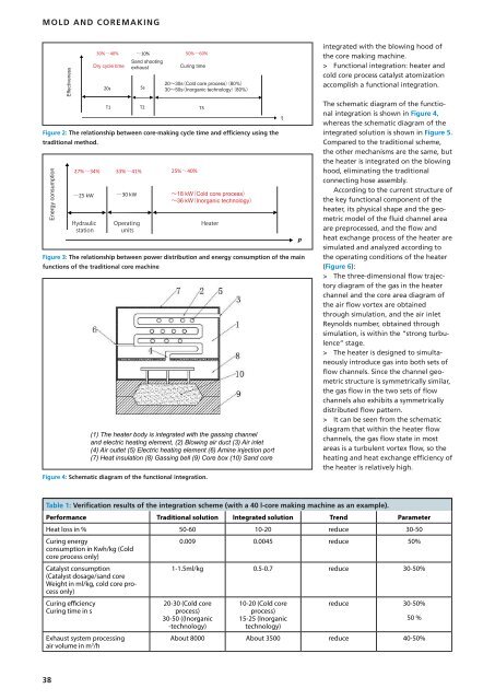
Figure 3: The relationship between power distribution and energy consumption of the main<br />
functions of the traditional core machine<br />
(1) The heater body is integrated with the gassing channel<br />
and electric heating element, (2) Blowing air duct (3) Air inlet<br />
(4) Air outlet (5) Electric heating element (6) Amine injection port<br />
(7) Heat insulation (8) Gassing bell (9) Core box (10) Sand core<br />
Figure 4: Schematic diagram of the functional integration.<br />
2030sCold core process 80%<br />
3050sInorganic technology 80%<br />
Figure 2: The relationship between core-making cycle time and efficiency using the<br />
traditional method.<br />
P<br />
integrated with the blowing hood of<br />
the core making machine.<br />
> Functional integration: heater and<br />
cold core process catalyst atomization<br />
accomplish afunctional integration.<br />
The schematic diagram of the functional<br />
integration is shown in Figure 4,<br />
whereas the schematic diagram of the<br />
integrated solution is shown in Figure 5.<br />
Compared to the traditional scheme,<br />
the other mechanisms are the same, but<br />
the heater is integrated on the blowing<br />
hood, eliminating the traditional<br />
connecting hose assembly.<br />
According tothe current structure of<br />
the key functional component of the<br />
heater, its physical shape and the geometric<br />
model of the fluid channel area<br />
are preprocessed, and the flow and<br />
heat exchange process of the heater are<br />
simulated and analyzed according to<br />
the operating conditions of the heater<br />
(Figure 6):<br />
> The three-dimensional flow trajectory<br />
diagram of the gas in the heater<br />
channel and the core area diagram of<br />
the air flow vortex are obtained<br />
through simulation, and the air inlet<br />
Reynolds number, obtained through<br />
simulation, is within the “strong turbulence”<br />
stage.<br />
> The heater is designed to simultaneously<br />
introduce gas into both sets of<br />
flow channels. Since the channel geometric<br />
structure is symmetrically similar,<br />
the gas flow in the two sets of flow<br />
channels also exhibits asymmetrically<br />
distributed flow pattern.<br />
> Itcan be seen from the schematic<br />
diagram that within the heater flow<br />
channels, the gas flow state in most<br />
areas is aturbulent vortex flow, sothe<br />
heating and heat exchange efficiency of<br />
the heater is relatively high.<br />
Table 1: Verification results of the integration scheme (with a40l-core making machine as an example).<br />
Performance Traditional solution Integrated solution Trend Parameter<br />
Heatloss in % 50-60 10-20 reduce 30-50<br />
Curing energy<br />
0.009 0.0045 reduce 50%<br />
consumption in Kwh/kg (Cold<br />
core process only)<br />
Catalyst consumption<br />
1-1.5ml/kg 0.5-0.7 reduce 30-50%<br />
(Catalystdosage/sand core<br />
Weightinml/kg,cold core process<br />
only)<br />
Curing efficiency<br />
Curing time in s<br />
reduce 30-50%<br />
Exhaust system processing<br />
airvolumeinm 3 /h<br />
20-30 (Cold core<br />
process)<br />
30-50 ((Inorganic<br />
-technology)<br />
10-20 (Cold core<br />
process)<br />
15-25 (Inorganic<br />
technology)<br />
50 %<br />
About 8000 About 3500 reduce 40-50%<br />
38