Flight 207: Ariane 5 ECA/Echostar-17 - Astrium - EADS
Flight 207: Ariane 5 ECA/Echostar-17 - Astrium - EADS
Flight 207: Ariane 5 ECA/Echostar-17 - Astrium - EADS

Create successful ePaper yourself
Turn your PDF publications into a flip-book with our unique Google optimized e-Paper software.
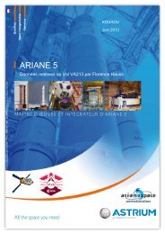
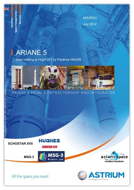
ARIANE 5<br />
Data relating to <strong>Flight</strong> <strong>207</strong> by Florence HAUSS<br />
ECHOSTAR XVII<br />
MSG-3<br />
KOUROU<br />
July 2012
Data relating to <strong>Flight</strong> <strong>207</strong><br />
<strong>Flight</strong> <strong>207</strong> <strong>Ariane</strong> 5<br />
Satellites: ECHOSTAR XVII – MSG-3<br />
Content<br />
1. Introduction ................................................................. 3<br />
2. Launcher L563 ............................................................ 3<br />
3. Mission V<strong>207</strong> .............................................................. 3<br />
4. Payloads ..................................................................... 3<br />
5. Launch campaign........................................................ 3<br />
6. Launch window ........................................................... 3<br />
7. Final countdown.......................................................... 3<br />
8. <strong>Flight</strong> sequence........................................................... 3<br />
9. ASTRIUM and the ARIANE programmes ...................... 3<br />
2
Data relating to <strong>Flight</strong> <strong>207</strong><br />
1. Introduction<br />
<strong>Flight</strong> <strong>207</strong> is the 63 rd <strong>Ariane</strong> 5 launch and the third in 2012. An ARIANE 5 <strong>ECA</strong> (Cryogenic<br />
Evolution type A), the most powerful version in the ARIANE 5 range, will be used for this flight.<br />
<strong>Flight</strong> <strong>207</strong> is a commercial mission for <strong>Ariane</strong> 5. The L563 launcher is the seventh in the A5<strong>ECA</strong><br />
family to be delivered by ASTRIUM ST to <strong>Ariane</strong>space as part of the PB production batch. The<br />
PB production contract was signed in March 2009 to guarantee continuity of the launch service<br />
after completion of the PA batch comprising 30 launchers. The PB production batch comprises<br />
35 A5<strong>ECA</strong> launchers and covers the period from 2010 to 2016. L563 is consequently the thirtyseventh<br />
complete launcher to be delivered to <strong>Ariane</strong>space, integrated and checked out under<br />
ASTRIUM responsibility in the Launcher Integration Building (BIL).<br />
In a dual-payload configuration using the SYLDA 5 “B” system and a long pattern fairing (total<br />
height: <strong>17</strong> m), the launcher is the communications satellites ECHOSTAR XVII in the upper<br />
position and MSG-3 in the lower position.<br />
Installed inside the long pattern fairing built by: RUAG Aerospace AG<br />
ECHOSTAR built by: SS/LORAL<br />
Strapped to a type PAS 1194C adaptor built by: <strong>EADS</strong>-CASA<br />
Placed on a MFD-C shock absorber built by: CASA<br />
Located inside the SYLDA 5 B built by: ASTRIUM ST<br />
MSG-3 built by: Thales Alenia Space<br />
Strapped to a type PAS 1666VS adaptor built by: RUAG<br />
Placed on a MFD-C, PSAD and MFD-D shock absorbers built by: CASA<br />
Operations in the Final Assembly Building (BAF) – where the satellites are<br />
integrated with the launcher – and actual launch operations on the<br />
ARIANE 5 launch pad (ELA3) are coordinated by <strong>Ariane</strong>space.<br />
3
Data relating to <strong>Flight</strong> <strong>207</strong><br />
2. Launcher L563<br />
Description<br />
The upper composite is mounted on the main cryogenic stage (EPC) and<br />
incorporates:<br />
• Fairing<br />
• SYLDA 5 payload carrier structure,<br />
• The Upper Composite, which comprises:<br />
• ESC-A cryogenic upper stage<br />
• Vehicle Equipment Bay<br />
• 3936 cone<br />
The lower composite incorporates:<br />
• EPC (H<strong>17</strong>5) main cryogenic stage with the new Vulcain 2 engine<br />
• two EAP (P240) solid propellant strap-on boosters secured on either<br />
side of the EPC<br />
Type-C main cryogenic stage:<br />
The EPC is over 30 m high. It has a diameter of 5.4 m and an empty mass of<br />
only 14.1 metric tons. It essentially comprises:<br />
• large aluminium alloy tank;<br />
• thrust frame transmitting engine thrust to the stage;<br />
• forward skirt connecting the EPC to the upper composite, and transmitting the thrust<br />
generated by the two solid propellant strap-on boosters.<br />
Liquid helium sub-system capacity<br />
© ASTRIUM ST<br />
4
Data relating to <strong>Flight</strong> <strong>207</strong><br />
Compared with the ARIANE 5 “generic” version of the main stage, the main changes are<br />
integration of the Vulcain 2 engine (generating 20% more thrust than the Vulcain 1), lowering of<br />
the tank common bulkhead, and strengthening of the forward skirt and thrust frame structures.<br />
As in the case of the previous A5 <strong>ECA</strong> launcher (L521) used for flight 164, the Vulcain 2 has<br />
undergone a number of changes, principally to the nozzle (shortened and strengthened) and<br />
the cooling system (dump-cooling).<br />
The tank is divided into two compartments containing <strong>17</strong>5 tons propellant (approximately 25<br />
tons liquid hydrogen and 149.5 tons liquid oxygen). The Vulcain 2 engine delivers of the order<br />
of 136 tons thrust, and is swivel-mounted (two axes) for attitude control by the GAM engine<br />
actuation unit. The main stage is ignited on the ground, so that its correct operation can be<br />
checked before authorising lift-off.<br />
The main stage burns continuously for about 539 s, and delivers the essential part of the kinetic<br />
energy required to place the payloads into orbit.<br />
The main stage also provides a launcher roll control function during the powered flight phase by<br />
means of the SCR (roll control system).<br />
On burnout at an altitude of <strong>17</strong>2 km for this mission, the stage separates from the upper<br />
composite and falls back into the Atlantic Ocean.<br />
Type-C solid propellant strap-on boosters:<br />
Each booster is over 31 m high, and has a diameter of 3 m and an empty mass of 38 tons.<br />
Each booster contains 240 tons solid propellant, and essentially comprises:<br />
• booster case assembled from seven steel rings,<br />
• steerable nozzle (pressure ratio Σ = 11), operated by a nozzle actuation unit (GAT),<br />
• propellant in the form of three segments.<br />
Equipment displayed at the Paris Air Show in 2001<br />
The boosters (EAP) are ignited 6.05 s after the Vulcain engine, i.e. 7.05 s from H0. Booster<br />
thrust varies in time (approx. 600 tons on lift-off or over 90% of total thrust, with a maximum of<br />
650 tons in flight). EAP burn time is about 135 s, after which the boosters are separated from<br />
the EPC by cutting the pyrotechnic anchor bolts, and fall back into the ocean.<br />
5
Data relating to <strong>Flight</strong> <strong>207</strong><br />
Compared with the ARIANE 5 “generic” version of the booster stage, the main changes include<br />
the elimination of one GAT cylinder, overloading of segment S1 to increase thrust on lift-off, and<br />
the use of a reduced mass nozzle (this reduces the mass of the structure by about 1.8 ton).<br />
Type-A cryogenic upper stage:<br />
The ESC-A 3 rd stage has been developed for the ARIANE 5 <strong>ECA</strong> version of the ARIANE 5 Plus<br />
launcher, and is based on the HM7B engine previously used for the 3 rd stage of the <strong>Ariane</strong> 4<br />
launcher.<br />
The ESC-A stage comprises:<br />
• two tanks containing 14.7 tons propellant (LH2 and LOX),<br />
• HM7B engine delivering 6.5 tons thrust in vacuum for a burn time of about 950 s. The<br />
HM7B nozzle is swivel-mounted (two axes) for attitude control.<br />
To meet the needs of the mission, the ESC-A stage has a single helium sphere to cover the<br />
stage tank pressurisation and solenoid valve control requirements.<br />
The ESC-A and the SCAR system<br />
The ESC-A delivers the additional energy required to place the payloads into target orbit. This<br />
stage also provides a roll control function for the upper composite during the powered flight<br />
phase, and orients the payloads ready for separation during the ballistic phase using the SCAR<br />
(attitude and roll control system).<br />
6
Data relating to <strong>Flight</strong> <strong>207</strong><br />
ESC-A thrust frame<br />
© <strong>EADS</strong> ST<br />
The C-Fibre Placement type Equipment Bay:<br />
<strong>Ariane</strong> 5 <strong>ECA</strong> launcher in transit to launch pad ZL3 for the<br />
launch sequence rehearsal (RSL)<br />
© Ds23230ESA/ARIANESPACE/Service optique CSG<br />
The vehicle equipment bay (VEB) is a cylindrical carbon structure mounted on the ESC-A<br />
stage. The VEB contains part of the electrical equipment required for the mission (two OBCs,<br />
two inertial guidance units, sequencing electronics, electrical power supplies, telemetry<br />
equipment, etc.). For the tenth time, the VEB cylinder and cone have been produced using a<br />
new process involving depositing carbon fibres on a mould before baking of the structure.<br />
The upper composite (ESC-A stage + VEB + 3936 cone) for launcher L563 was assembled<br />
for the twenty-third time at the <strong>Astrium</strong> ST site in Bremen, in order to meet needs resulting from<br />
the increase in production rates for the coming years.<br />
Assembly of the upper composite at the Bremen site<br />
© <strong>EADS</strong> <strong>Astrium</strong><br />
7
Data relating to <strong>Flight</strong> <strong>207</strong><br />
Nose fairing:<br />
The ogival nose fairing protects the payloads during the<br />
atmospheric flight phase (acoustic protection on lift-off<br />
and during transonic flight, aerothermodynamic flux).<br />
A long pattern fairing is used for this mission. It has a<br />
height of <strong>17</strong> m and a diameter of 5.4 m.<br />
The fairing structure includes two half-fairings comprising<br />
10 panels. These sandwich panels have an expanded<br />
aluminium honeycomb core and two carbon fibre/resin<br />
skins.<br />
The fairing is separated from the launcher by two<br />
pyrotechnic devices, one horizontal (HSS) and the other<br />
vertical (VSS). The vertical device imparts the impulse<br />
required for lateral separation of the two half-fairings.<br />
The fairing has been coated with a lighter FAP (Fairing<br />
Acoustic Protection) product since flight <strong>17</strong>5-L534.<br />
The fairing production line<br />
© RUAG Aerospace AG<br />
8
Data relating to <strong>Flight</strong> <strong>207</strong><br />
SYLDA 5 (ARIANE 5 dual-launch system):<br />
This system provides for a second main payload inside one of the three fairing models. There<br />
are six different versions of this internal structure which has a diameter of 4.6 m. SYLDA height<br />
varies between 4.9 and 6.4 m (0.3 m increments) for useful payload volumes between 50 and<br />
65 m 3 .<br />
For this mission, a SYLDA 5 ‘B’ with a height of 6.1 m will be used. It enables the carriage of a<br />
payload in the lower position, MSG-3. For the second time on this flight, the structure was<br />
manufactured using a new “co-curing” method, enabling the industrial process to be<br />
rationalised.<br />
Sylda 5 No. 51-B for launcher L563 at Les Mureaux<br />
© ASTRIUM ST<br />
9
Data relating to <strong>Flight</strong> <strong>207</strong><br />
3. Mission V<strong>207</strong><br />
Payload mission<br />
The main mission of <strong>Flight</strong> <strong>207</strong> is to place the ECHOSTAR XVII and MSG-3 commercial<br />
payloads into nearly standard GTO orbit:<br />
Apogee altitude 35,786 km<br />
Perigee altitude 250 km<br />
Inclination 6.0°<br />
Perigee argument <strong>17</strong>8°<br />
Ascending node longitude -121.294°(*)<br />
(*) in relation to a fixed axis, frozen at H0 - 3s and passing through the ELA3 launch complex in<br />
Kourou.<br />
The mass of ECHOSTAR XVII is 6,100 kg, with 2,032 kg for MSG-3.<br />
Allowing for the adaptors, MDFs, the PSAD and the SYLDA 5 structure, total performance<br />
required from the launcher for the orbit described above is 9,635 kg.<br />
It should be remembered that the maximum performance offered by the <strong>Ariane</strong> 5 ESC-A<br />
launcher is about 10,000 kg (performance achieved with the latest launch V201 on 22 nd April,<br />
with launcher L558) for a standard orbit inclined at 6°.<br />
This also demonstrates the launcher's adaptability in terms of payload mass.<br />
10
Data relating to <strong>Flight</strong> <strong>207</strong><br />
<strong>Flight</strong> phases<br />
Taking H0 as the basic time reference (1 s before the hydrogen valve of the EPC Vulcain engine<br />
combustion chamber opens), Vulcain ignition occurs at H0 + 2.7 s. Confirmation of nominal<br />
Vulcain operation authorises ignition of the two solid propellant boosters (EAP) at H0 + 7.05 s,<br />
leading to launcher lift-off.<br />
Lift-off mass is about 774 tons, and initial thrust 13,000 kN (of which 90% is delivered by the<br />
EAPs).<br />
After a vertical ascent lasting 5s to enable the launcher to clear the ELA3 complex, including<br />
the lightning arrestor pylon in particular, the launcher executes a tilt operation in the trajectory<br />
plane, followed by a roll operation 5 seconds later to position the plane of the EAPs<br />
perpendicularly to the trajectory plane. The launch azimuth angle for this mission is 88° with<br />
respect to North.<br />
The “EAP” flight phase continues at zero angle of incidence throughout atmospheric flight, up<br />
to separation of the boosters.<br />
The purpose of these operations is to:<br />
• optimise trajectory and thus maximise performance;<br />
• obtain a satisfactory radio link budget with the ground stations;<br />
• meet in-flight structural loading and attitude control constraints.<br />
The EAP separation sequence is initiated when an acceleration threshold is detected, when<br />
the solid propellant thrust level drops. Actual separation occurs within one second.<br />
11
Data relating to <strong>Flight</strong> <strong>207</strong><br />
This is reference time H1, and occurs at about H0 + 141 s at an altitude of 67 km and a relative<br />
velocity of 2,012 m/s.<br />
For the remainder of the flight (EPC flight phase), the launcher follows an attitude law controlled<br />
in real time by the on-board computer, based on information received from the navigation unit.<br />
This law optimises the trajectory by minimising burn time and consequently consumption of<br />
propellant.<br />
The fairing is jettisoned during the EPC flight phase as soon as aerothermodynamic flux levels<br />
are sufficiently low not to impact the payload. For this mission, separation of the payload will<br />
occur about 197 s after lift-off at an altitude of 107 km.<br />
The EPC powered flight phase is aimed at a predetermined orbit established in relation to<br />
safety requirements, and the need to control the operation when the EPC falls back into the<br />
Atlantic Ocean.<br />
Shutdown of the Vulcain engine occurs when the following target orbit characteristics have<br />
been acquired:<br />
Apogee altitude <strong>17</strong>2.3 km<br />
Perigee altitude -1,064.3 km<br />
Inclination 7.2°<br />
Perigee argument -38.3°<br />
Ascending node longitude -124.2°<br />
This is time reference H2. It happens at H0 + 539.2 s.<br />
The main cryogenic stage (EPC) falls back into the Atlantic Ocean after separation (see below),<br />
breaking up at an altitude of between 80 and 60 km under the loads generated by atmospheric<br />
re-entry.<br />
The stage must be depressurised (passivated) to avoid any risk of explosion of the stage due<br />
to overheating of residual hydrogen. A hydrogen tank lateral nozzle, actuated by a time delay<br />
relay initiated on EPC separation, is used for this purpose.<br />
This lateral thrust is also used to spin the EPC, and thus limit breakup-induced debris<br />
dispersion on re-entry.<br />
The main cryogenic stage angle of re-entry is -2.6°. The longitude of the point of impact is<br />
4.1°W.<br />
The subsequent ESC-A powered flight phase lasts about 16 minutes. This phase is terminated<br />
by a command signal from the OBC, when the computer estimates, from data calculated by the<br />
inertial guidance unit, that the target orbit has been acquired.<br />
This is time reference H3. It happens at H0 + 1,497.4 s.<br />
12
Data relating to <strong>Flight</strong> <strong>207</strong><br />
The purpose of the following ballistic phase is to ensure:<br />
• Pointing of the upper composite in the direction required by ECHOSTAR XVII and<br />
MSG-3 and then in that required for SYLDA 5,<br />
• Composite slow transverse spin-up before separation ECHOSTAR XVII<br />
• Triple-axis stabilisation before separation of SYLDA 5,<br />
• Composite slow spin-up at 30.7°/s before separation of MSG-3,<br />
• Separation of ECHOSTAR XVII, SYLDA 5 and MSG-3,<br />
• Final spin-up of the composite at 45°/s,<br />
• Passivation of the ESC-A stage pressurised LOX tank and LH2 tank, preceded by a prepassivation<br />
phase involving simultaneous opening of the eight SCAR nozzles. These<br />
operations contribute to short- and medium-term management of the mutual distancing<br />
of objects in orbit.<br />
The ballistic phase for the mission comprises 23 elementary phases described hereafter. These<br />
include separation of ECHOSTAR XVII (phase 5), SYLDA 5 separation (phase 10), and MSG-3<br />
separation (phase 13).<br />
13
Data relating to <strong>Flight</strong> <strong>207</strong><br />
14
Data relating to <strong>Flight</strong> <strong>207</strong><br />
Staging of the various elements generated by the ballistic phase is described below.<br />
15
Data relating to <strong>Flight</strong> <strong>207</strong><br />
The launcher will be under telemetry monitoring by tracking stations in Kourou, Galliot, Natal,<br />
Ascension Island, Libreville and Malindi throughout the mission.<br />
With the performance necessary for this mission, the trajectory includes two periods of visibility<br />
loss: between Natal and Ascension (~84 s.) and between Ascension and Libreville (~29 s.):<br />
16
Data relating to <strong>Flight</strong> <strong>207</strong><br />
The following plates show:<br />
• Situation of the main events of the flight,<br />
• Evolution of launcher altitude during powered flight.<br />
<strong>17</strong>
Data relating to <strong>Flight</strong> <strong>207</strong><br />
4. Payloads<br />
ECHOSTAR XVII<br />
EchoStar Corporation is the premier global provider of FSS (Fixed Satellite Services), and TV<br />
and video delivery solutions. Headquartered in Englewood, CO, EchoStar has pioneered<br />
advancements in the set-top box and satellite industries for nearly 30 years. EchoStar Corp.<br />
owns or manages a fleet of 14 satellites (as of end 2011) that are used to deliver innovative<br />
video and broadband data services EchoStar Corp. broadcasts over 6800 channels.<br />
Hughes Network Systems, LLC (HUGHES), a wholly owned subsidiary of EchoStar Corp., is<br />
the world’s leading provider of satellite broadband for home, offices and government services,<br />
delivering innovative network technologies and managed services. HughesNet® is the #1 highspeed<br />
satellite Internet service in the US with over 640,000 subscribers. HUGHES has shipped<br />
more than 2.8 million systems to customers in over 100 countries, representing over 50-percent<br />
market share. HUGHES owns and operates service businesses throughout the U.S., Europe,<br />
India, and Brazil delivering continent-wide Hughes broadband satellite and terrestrial connectivity<br />
and an ever growing range of applications—such as high-speed Internet/Intranet access,<br />
distance learning, business TV, digital signage, and Voice over IP (VoIP).<br />
ECHOSTAR XVII – Artist’s impression<br />
© HUGHES<br />
18
Data relating to <strong>Flight</strong> <strong>207</strong><br />
The satellite<br />
EchoStar XVII is built by SPACE SYSTEMS/LORAL. It is based on the LS 1300E BUS satellite<br />
platform, which, all satellites taken together, represents a total of more than 1900 years in<br />
orbit.<br />
The launch of EchoStar XVII using JUPITER broadband technology will provide subscribers<br />
with a rate of more than 100 gigabits per second. Its multi-beam architecture will enhance and<br />
reinforce coverage and will target areas of North America where demand is greatest. It will thus<br />
supplement SPACEWAY 3, launched by <strong>Ariane</strong> 5 on 14 August 2007, and which provides<br />
uniform coverage of the USA. EchoStar XVII will provide high-speed internet access to nearly 2<br />
million extra subscribers, offering them unique media access.<br />
The main characteristics of the satellite are recalled in the following table:<br />
* Dimensions<br />
• 8.00 x 3.20 x 3.10 m<br />
• In-orbit span 26.07 m<br />
* Mass • Lift-off 6,100 kg<br />
* Power<br />
* Propulsion<br />
* Stabilisation<br />
* Transmission<br />
capacity<br />
• Payload power: between <strong>17</strong>.7 and 16.1 kW<br />
• 3 Li-Ion batteries<br />
• Biliquid propellant tanks (MMH & NTO)<br />
• •455N-apogee engine and 22N-nozzles for in-orbit control<br />
• Slow transverse spin-up at separation<br />
• Triple-axis stabilisation in orbit<br />
• 60 Ka-band beams<br />
• 4 antennas and 2 ‘Horns’<br />
* Orbit Position • 107.1° West<br />
* Coverage USA<br />
ECHOSTAR XVII<br />
coverage zones<br />
© HUGHES<br />
Expected lifetime exceeds 15 years<br />
19
Data relating to <strong>Flight</strong> <strong>207</strong><br />
ECHOSTAR XVII<br />
in the anechoic chamber<br />
.© HUGHES<br />
20
Data relating to <strong>Flight</strong> <strong>207</strong><br />
MSG-3<br />
The Meteosat Second Generation (MSG) system<br />
is responsible for observation of the atmosphere<br />
from geostationary orbit at longitude 0°. As part of<br />
the global operational satellite-based meteorology<br />
system, MSG follows on from the first generation of<br />
satellites and the original Meteosat Operational<br />
Program (MOP) system. The MSG programme is a<br />
complete system, comprising a ground segment and<br />
four satellites. The European Space Agency (ESA)<br />
runs the MSG programme on behalf of Eumetsat,<br />
the European satellite-based meteorology organisation,<br />
which today comprises 26 member states and 5<br />
cooperating states.<br />
The space segment consists of two MSG satellites,<br />
in orbit simultaneously to guarantee the high level of<br />
availability required for the mission, with one satellite<br />
operational and the other on standby. MSG-1 (MET-<br />
8) was launched in August 2002 and MSG-2 (MET-<br />
9) in December 2005. The launch of MSG-4 is<br />
planned for 2015. All the MSG satellites are built by<br />
a European consortium headed by Thales Alenia<br />
Space.<br />
The MSG satellites work in conjunction with the low-Earth orbit weather satellites, such as the<br />
European METOP. The advantage of geostationary satellite data is that they are global and<br />
permanent. They are thus the basis for the work of the forecasters, who then refine the information<br />
using that provided by the low-orbit satellites, which scan the surface of the globe with<br />
extremely high precision.<br />
The Météosat Programme is part of the<br />
World Weather Watch.<br />
21
Data relating to <strong>Flight</strong> <strong>207</strong><br />
The satellite<br />
Improved imaging and data transmission performance:<br />
• Improved imaging quality, with a significant rise in the number of observation channels, radiometric<br />
performance and data quantification, plus an increase in the number of repeat cycles.<br />
This capacity makes a substantial contribution to real-time weather forecasting and to digital<br />
forecasting models, without forgetting the environmental and climatology watch.<br />
• The meteorological telecommunications payload, which transmits the images acquired by the<br />
MSG’s optical instrumentation, offers greater data transmission capacity and is more efficient<br />
than that of the first generation of satellites.<br />
These satellites provide two additional missions: relaying of distress signals for the Search &<br />
Rescue (S&R) system and the GERB (Geostationary Earth Radiation Budget) instrument.<br />
22
Data relating to <strong>Flight</strong> <strong>207</strong><br />
To produce maps and enable weather forecasts to be made, the Meteosat satellites are<br />
equipped with a radiometer called SEVIRI (Spinning Enhanced Visible and Infra Red Imager).<br />
This imaging instrument, designed and built by <strong>Astrium</strong>, “sees” climatic phenomena in the<br />
visible and infrared, over one third of the globe’s surface (MSG-3 will “see” a zone ranging<br />
approximately from the North Pole to the South Pole and from Chile to India). This is the<br />
tenth radiometer of the Meteosat constellation, the first examples of which operated for up to 19<br />
years in space. Since the first model entered service, SEVIRI has been the world’s benchmark<br />
instrument for the design of the next generation of radiometers. It is the most efficient meteorological<br />
instrument in orbit.<br />
SEVIRI offers some major technological advances over<br />
the first generation Meteosat radiometers. It is capable<br />
of detecting 12 spectral bands instead of three, providing<br />
even more detailed observations. It offers a level of<br />
resolution three times greater than that of the previous<br />
radiometers (up to one kilometre), allowing on-demand<br />
close-ups of local climatic phenomena. Finally, SEVIRI<br />
is capable of scanning the surface of the Earth in just<br />
15 minutes, as opposed to 30 minutes for the previous<br />
generation.<br />
<strong>EADS</strong> <strong>Astrium</strong> produced the image processing system (IMPF) which provides the link between<br />
the SEVIRI instrument and the end-user. This required development, testing and installation of<br />
this software on the Eumetsat ground station in Darmstadt, Germany. Moreover, <strong>EADS</strong> <strong>Astrium</strong><br />
is responsible for training the Eumetsat engineers and will handle maintenance of the<br />
software for two years following delivery.<br />
23
Data relating to <strong>Flight</strong> <strong>207</strong><br />
MSG-3<br />
during integration<br />
©Thales-Alenia Space<br />
24
Data relating to <strong>Flight</strong> <strong>207</strong><br />
* Dimensions • Ø3212 x 2.36 m, total height 3.742 m<br />
* Mass • Lift-off 2,035 kg<br />
* Power<br />
• Payload power: between 700 and 800 W<br />
• 2 Cd / Ni batteries<br />
* Propulsion • Biliquid propellant tanks (MMH & MON-1)<br />
* Stabilisation<br />
* Transmission<br />
capacity<br />
* Orbit Position • 0° West<br />
MSG-3<br />
during a spin test<br />
©Thales-Alenia Space<br />
• Spin et 30°/s at separation<br />
• Spin at 600°/s in orbit<br />
• 60 Ka-band beams<br />
• 4 antennas and 2 ‘Horns’<br />
* Coverage Europe, Africa, Atlantic Ocean, East of South America<br />
Expected lifetime exceeds 7 years<br />
25
Data relating to <strong>Flight</strong> <strong>207</strong><br />
5. Launch campaign<br />
The <strong>Ariane</strong> 5 main cryogenic stage (EPC) in the<br />
integration dock at Les Mureaux, France, in course of<br />
preparation for tilt and containerization<br />
© <strong>EADS</strong> ST photo: Studio Bernot<br />
The main cryogenic stage loading<br />
on board the "Toucan" in the port of<br />
Le Havre for shipment to French<br />
Guiana<br />
© <strong>EADS</strong> ST photo: JL<br />
ESC-A undergoing integration at ASTRIUM Bremen<br />
© <strong>EADS</strong> ST<br />
26
Data relating to <strong>Flight</strong> <strong>207</strong><br />
Principal phases of the <strong>Flight</strong> <strong>207</strong> launch campaign:<br />
Arrival of MSG-3 in Kourou April 13, 2012<br />
EPC depreservation and erection in the launcher integration building<br />
(BIL)<br />
April 19, 2012<br />
Transfer of Solid Booster Stages (EAP) April 20, 2012<br />
Mating of the EAPs with the EPC April 21, 2012<br />
Depreservation and erection of the Upper Composite April 25, 2012<br />
Launcher Synthesis Control April 27, 2012<br />
Arrival of ECHOSTAR XVII in Kourou May 10, 2012<br />
V206: Success of the JCSAT-13 / VINASAT-2 mission May 15, 2012<br />
Launcher acceptance by <strong>Ariane</strong>space May 29, 2012<br />
Transfer from BIL to BAF May 30, 2012<br />
ECHOSTAR XVII fuelling<br />
Assembly on its adaptor<br />
Transfer to the BAF<br />
Integration on the SYLDA<br />
MSG-3 fuelling<br />
Assembly on its adaptor<br />
Transfer to the BAF<br />
Integration on the launcher<br />
From June 15 to June 18<br />
June 19, 2012<br />
June 20, 2012<br />
June 21, 2012<br />
From June 18 to June 21<br />
June 22, 2012<br />
June 25, 2012<br />
June 26, 2012<br />
Integration of the fairing on the SYLDA June 22, 2012<br />
Integration of the composite (ECHOSTAR XVII + PAS 1194C + SYLDA<br />
+ fairing) on the launcher<br />
June 27, 2012<br />
General rehearsal June 29, 2012<br />
<strong>Flight</strong> Readiness Review<br />
Arming of the launcher<br />
Launcher transfer from the BAF to the Pad (ZL3)<br />
Fuelling of the EPC helium sphere<br />
July 3, 2012<br />
July 4, 2012<br />
Final countdown July 5, 2012<br />
27
Data relating to <strong>Flight</strong> <strong>207</strong><br />
Kourou: erection of the Upper Composite in<br />
the Launcher Integration Building (BIL)<br />
© ESA/ARIANESPACE/Service optique CSG<br />
Kourou: transfer of the launcher<br />
from the Launcher Integration<br />
Building (BIL) to the Final Assembly<br />
Building (BAF)<br />
Kourou: transfer from the Final Assembly Building<br />
(BAF) to the pad for the Launch Sequence Rehearsal<br />
(RSL)<br />
© ESA/ARIANESPACE/Service optique CSG<br />
28
Data relating to <strong>Flight</strong> <strong>207</strong><br />
6. Launch window<br />
The window for a launch on July 5, 2012 is with H0 at 21:36 (UT). The closing of the window is<br />
at 22:05. (UT).<br />
The launch window will last 29 minutes:<br />
Washington, DC time<br />
July 5, 2012<br />
<strong>17</strong>:36 - 18:05<br />
Kourou time<br />
July 5, 2012<br />
18:36 - 19:05<br />
Paris time<br />
July 5, 2012<br />
23:36 - 00:05<br />
UNIVERSAL TIME<br />
July 5, 2012<br />
21:36 - 22:05<br />
The launch window for this mission is dictated principally by launcher and payloads constraints.<br />
29
Data relating to <strong>Flight</strong> <strong>207</strong><br />
7. Final countdown<br />
The final countdown includes all operations for preparation of the launcher, satellites and<br />
launch base. Correct execution of these operations authorises ignition of the Vulcain engine,<br />
followed by the solid propellant boosters at the selected launch time, as early as possible inside<br />
the launch window for the satellites. The countdown terminates with a synchronised sequence<br />
managed by the <strong>Ariane</strong> ground checkout computers, starting at H0 - 7 min. In some cases, a<br />
pre-synchronised sequence may be necessary to optimise fuelling of the main cryogenic stage<br />
(*). If a countdown hold pushes time H0 outside the launch window, the launch is postponed to<br />
D+1 or D+2, depending on the nature of the problem and the solution adopted.<br />
H0 - 7 hours 30<br />
H0 - 6 hours<br />
H0 - 5 hours<br />
H0 - 5 hours<br />
H0 - 4 hours<br />
Checkout of electrical systems.<br />
Flushing and configuration of the EPC and Vulcain engine for fuelling<br />
and chill-down<br />
Final preparation of the launch pad: closure of doors, removal of safety<br />
barriers, configuration of the fluid circuits for fuelling.<br />
Loading of the flight program<br />
Testing of radio links between the launcher and BLA<br />
Alignment of inertial guidance units<br />
Evacuation of personnel from the launch pad<br />
Fuelling of the EPC in four phases:<br />
pressurisation of the ground tanks (30 minutes)<br />
chill-down of the ground lines (30 minutes)<br />
fuelling of the stage tanks (2 hours)<br />
topping up (up to synchronised sequence)<br />
Pressurisation of the attitude control and command systems:<br />
(GAT for the EAPs and GAM for the EPC)<br />
Fuelling of the ESC-A stage in four phases:<br />
pressurisation of the ground tanks (30 minutes)<br />
chill-down of the ground lines (30 minutes)<br />
fuelling of the stage tanks (1 hour)<br />
topping up (up to synchronised sequence)<br />
H0 - 3 hours Chill-down of the Vulcain engine<br />
H0 - 30 minutes Preparation of the synchronised sequence<br />
H0 - 7 minutes Beginning of the synchronised sequence (*)<br />
(*) The standard synchronised sequence will start at H0 - 7 minutes, incorporating all final<br />
launcher operations leading to lift-off. By comparison, the stretched synchronised sequence for<br />
flight <strong>17</strong>3 commenced at H0 - 12 minutes, to cater for top-up LOX fuelling of the EPC stage to<br />
meet mission performance requirements.<br />
30
Data relating to <strong>Flight</strong> <strong>207</strong><br />
Synchronised sequence<br />
These operations are controlled exclusively and automatically by the ELA3 operational<br />
checkout-command (CCO) computer. During this sequence, all the elements involved in the<br />
launch are synchronised by the “countdown time” distributed by the CSG.<br />
During the initial phase (up to H0 - 6s), the launcher is gradually switched to its flight<br />
configuration by the CCO computer. If the synchronised sequence is placed on hold, the<br />
launcher is returned automatically to its configuration at H0 - 7 min.<br />
In the second irreversible phase of the sequence (H0 - 6 s to H0 - 3.2 s), the synchronised<br />
sequence is no longer dependent on CSG countdown time, and operates on an internal clock.<br />
The final phase is the launcher ignition phase. The ignition sequence is controlled directly by<br />
the on-board computer (OBC). The ground systems execute a number of actions in parallel with<br />
the OB ignition sequence.<br />
31
Data relating to <strong>Flight</strong> <strong>207</strong><br />
FLUID SYSTEMS ELECTRICAL SYSTEMS<br />
H0 - 6 min 30s<br />
Termination of topping up (LOX and LH2)<br />
LOX and LH2 topped up to flight value<br />
Launch pad safety flood valves opened<br />
H0 - 6 min<br />
Isolation of the ESC-A helium sphere<br />
H0 - 4 min<br />
<strong>Flight</strong> pressurisation of EPC tanks<br />
Isolation of tanks and start of EPC ground/OB<br />
interface umbilical circuit flushing<br />
Termination of ESC-A LOX topping up<br />
ESC-A LOX transition to flight pressure<br />
H0 - 3 min 40s: termination of ESC-A LH2 topping up<br />
H0 - 3 min 10s: ESC-A LH2 transition to flight<br />
pressure<br />
H0 - 2 min: Vulcain 2 bleeder valves opened<br />
Engine ground chill-down valve closed<br />
H0 - 1 min 5s<br />
Termination of ESC-A tank pressurisation from the<br />
ground, and start of ESC-A valve plate sealtightness<br />
checkout<br />
H0 - 30s<br />
Verification of ground/OB umbilical circuit<br />
flushing<br />
EPC flue flood valves opened<br />
H0 - 16.5 s<br />
Pressurisation of POGO corrector system<br />
Ventilation of fairing POP and VEB POE<br />
connectors and EPC shut down<br />
H0 - 12 s Flood valves opening command<br />
H0 - 6 min 30s<br />
Arming of pyrotechnic line safety barriers<br />
H0 - 3 min 30s: Calculation of ground H0 and<br />
verification that the second OBC has switched to<br />
the observer mode<br />
H0 - 3 min<br />
H0 loaded in the 2 OBCs<br />
H0 loaded in OBCs checked against ground H0<br />
H0 - 2 min 30s: Electrical heating of EPC and VEB<br />
batteries, and electrical heating of the Vulcain 2<br />
ignition system shut down<br />
H0 - 1 min 50s<br />
Pre-deflection of the HM7B nozzle<br />
H0 - 1 min 5s<br />
Launcher electrical power supply switched from<br />
ground to OB<br />
H0 - 37s<br />
Start-up of ignition sequence automatic control<br />
system<br />
Start-up of OB measurement recorders<br />
Arming of pyrotechnic line electric safety barriers<br />
H0 - 22s<br />
Activation of launcher lower stage attitude<br />
control systems<br />
Authorisation for switchover to OBC control<br />
32
Data relating to <strong>Flight</strong> <strong>207</strong><br />
H0 - 6s<br />
IRREVERSIBLE SEQUENCE<br />
Arming and ignition of AMEFs to burn hydrogen run-off during chill-down of the<br />
combustion chamber on Vulcain ignition<br />
Valve plate and cryogenic arm retraction commands<br />
H0 - 5.5s<br />
Ground information communication bus control switched to OBC<br />
H0 - 3s<br />
IGNITION SEQUENCE<br />
Checkout of computer status<br />
Switchover of inertial guidance systems to flight mode<br />
Helium pressurisation activated<br />
LOX and LH2 pressures monitored<br />
Navigation, guidance and attitude control functions activated<br />
H0 - 2.5s<br />
Verification of HM7B nozzle deflection<br />
H0 - 1.4s<br />
Engine flushing valve closed<br />
H0 - 0.2s<br />
Verification of acquisition of the “cryogenic arms retracted” report by the OBC at the<br />
latest moment<br />
H0 → H0 + 6.65s<br />
Vulcain engine ignition and verification of its correct operation<br />
(H0+1s corresponds to opening of the hydrogen chamber valve)<br />
H0 + 6.9s<br />
End of Vulcain engine checkout<br />
H0 + 7,05s<br />
Ignition of the EAPs<br />
33
Data relating to <strong>Flight</strong> <strong>207</strong><br />
8. <strong>Flight</strong> sequence<br />
time /H0<br />
(s)<br />
time/H0<br />
(mn)<br />
event<br />
altitude<br />
(km)<br />
mass<br />
- - - - EAP-EPC powered flight - - -<br />
7.30 0 ’ 07 ’’ Lift-off --- 774.4 0<br />
(t)<br />
Vreal<br />
(m/s)<br />
12.48 0 ’ 13 ’’ Start of tilt manoeuvre 0.09 747.6 36,1<br />
<strong>17</strong>.05 0 ’ <strong>17</strong> ’’ Start of roll manoeuvre 0.34 722.6 75,3<br />
32.05 0 ’ 32 ’’ End of roll manoeuvre 2.50 643.7 215,0<br />
48.4 0 ’ 49 ’’ Transsonic (Mach = 1) 6.66 578.3 323,2<br />
67.7 1 ’ 08 ’’ Speed at Pdyn max 13.39 500.0 519,9<br />
111.0 1 ’ 51 ’’<br />
141.4 2 ’ 21 ’’<br />
Transition to γmax<br />
(41.41 m/s 2 )<br />
Transition to γ = 6.15 m/s²<br />
H1<br />
39.4 309.3 1559<br />
66.8 252.5 2012<br />
142.2 2 ’ 22 ’’ EAP separation 67.5 <strong>17</strong>7.5 2013<br />
- - - - EPC powered flight - - - -<br />
197.4 3 ’ <strong>17</strong> ’’ Fairing jettisoned 107,4 157.5 2260<br />
325.0 5 ' 25 " Intermediate point 160.7 116.6 3252<br />
487.8 8 ’ 08 ’’ Acquisition Natal <strong>17</strong>2.5 64.1 5640<br />
537.3 8 ’ 57 ’’ Lost Galliot <strong>17</strong>1.9 48.2 6829<br />
539.2 8 ’ 59 ’’ EPC burnout (H2) <strong>17</strong>1.9 47.5 6884<br />
545.2 9 ’ 05 ’’ EPC separation <strong>17</strong>2.1 28.9 6910<br />
- - - - ESC-A powered flight - - - -<br />
549.2 9 ’ 09 ’’ ESC-A ignition <strong>17</strong>2.2 28.9 6912<br />
735.6 12 ’ 16 ’’ Lost Natal 165.3 26,2 7352<br />
819.1 13 ’ 39 ’’ Acquisition Ascension 160.5 24.9 7568<br />
877.8 14 ’ 38 ’’ Minimum altitude 159.0 24.1 7724<br />
1077.0 <strong>17</strong> ’ 57 ’’ Lost Ascension 184.4 21.1 8265<br />
1105.7 18 ’ 25 ’’ Acquisition Libreville 194.2 20.7 8341<br />
1260.0 21 ’ 00 ’’ Intermediate point 291.4 18.4 8752<br />
1389.1 23 ’ 09 ’’ Acquisition Malindi 447.1 16.4 9086<br />
1497.4 24 ’ 58 ’’ ESC-A burnout (H3-1) 644.1 14.8 9363<br />
34
Data relating to <strong>Flight</strong> <strong>207</strong><br />
time /H0<br />
(s)<br />
time/H0<br />
(mn)<br />
event<br />
altitude<br />
- - - - “Ballistic” phase - - -<br />
1503 25 ’ 03 ’’ Phase 3 Start of ECHOSTAR XVII orientation 656<br />
1614 26 ’ 54 ’’ Phase 4 Start of ECHOSTAR XVII slow transverse spin-up 927<br />
1655 27 ’ 35 ’’ ECHOSTAR XVII separation (H4.1) 1040<br />
1665 27 ’ 45 ’’ Phases 6 Upper composite despin 1068<br />
1670 27 ’ 50 ’’ Phases 7 to 9 SYLDA staging to orientation phases 1084<br />
1877 31 ’ <strong>17</strong> ’’ SYLDA separation (H4.2) <strong>17</strong>59<br />
1887 31 ’ 27 ’’ Phase 11 Start of MSG-3 orientation <strong>17</strong>95<br />
1962 32 ’ 42 ’’ Phase 12 Start of MSG-3 spin-up <strong>207</strong>1<br />
2051 34 ’ 11 ’’ MSG-3 separation (H4.3) 2411<br />
2061 34 ‘ 21 ’’ Phase 14 Upper composite despin 2450<br />
2116 35 ’ 16 ’’ Phase 15 Orientation to staging phases 2666<br />
2<strong>17</strong>8 36 ’ 18’’ Phases 16 to 19 ESC-A staging phases 29<strong>17</strong><br />
2486 41 ’ 26 ’’ Phase 20 ESC-A orientation for the final spin-up 4209<br />
2566 42 ’ 16 ’’ Phase 21 Start of spin-up at 45°/s 4551<br />
2667 44 ’ 27 ’’ Oxygen tank passivation (breakdown S34) 4983<br />
2942 49 ’ 02 ’’ ESC-A passivation (breakdown S37) 6154<br />
Note: This provisional flight sequence is coherent with the stage propulsion laws available at<br />
the time of drafting this document.<br />
(km)<br />
35
Data relating to <strong>Flight</strong> <strong>207</strong><br />
9. ASTRIUM and the ARIANE programmes<br />
<strong>Astrium</strong> Space Transportation, a Division of <strong>Astrium</strong>, is the European specialist for access to<br />
space and manned space activities. It develops and produces <strong>Ariane</strong> launchers, the Columbus<br />
laboratory and the ATV cargo carrier for the International Space Station, atmospheric re-entry<br />
vehicles, missile systems for France's deterrent force, propulsion systems and space<br />
equipment.<br />
<strong>EADS</strong> is a global leader in aerospace, defence and related services. In 2010, the Group –<br />
comprising Airbus, <strong>Astrium</strong>, Cassidian and Eurocopter – generated revenues of € 45.8<br />
billion and employed a workforce of about 122,000.<br />
<strong>Astrium</strong> is the number one company in Europe for space technologies and a wholly owned<br />
subsidiary of <strong>EADS</strong>, dedicated to providing civil and defence space systems and services. In<br />
2010, <strong>Astrium</strong> had a turnover of €5 billion and more than 15,000 employees in France, Germany,<br />
the United Kingdom, Spain and the Netherlands. Its three main areas of activity are<br />
<strong>Astrium</strong> Space Transportation for launchers and orbital infrastructure, <strong>Astrium</strong> Satellites for<br />
spacecraft and ground segment, and <strong>Astrium</strong> Services for comprehensive end-to-end solutions<br />
covering secure and commercial satcoms and networks, high security satellite communications<br />
equipment, bespoke geo-information and navigation services worldwide.<br />
<strong>Astrium</strong> has acquired extensive expertise, unrivalled in Europe, as industrial architect or prime<br />
contractor for large-scale strategic and space programs. This position is based on the<br />
company's ability to direct and coordinate the wealth of expertise required to design and<br />
develop complex projects.<br />
Further to the failure of launcher L5<strong>17</strong> in December 2002, the ministerial level conference<br />
organised by the European Space Agency on May 27, 2003 decided to appoint an industrial<br />
prime contractor to manage firstly <strong>Ariane</strong> 5 production activities and, secondly, development<br />
activities. Over and beyond the management requirement to master the chain of responsibilities<br />
for the entire <strong>Ariane</strong> 5 design and production cycle, the set economic target was to significantly<br />
reduce costs with respect to the modes of functioning in effect at the time.<br />
The PA production batch contract was signed in 2004 with these objectives, and <strong>Astrium</strong> ST,<br />
through an innovative industrial approach in the <strong>Ariane</strong> launchers' European environment and<br />
by adapting the management processes, successfully led launcher production as from the<br />
launching of unit L527 on March 11, 2006. The launch rate increased from 4 to 7 launchers per<br />
year while controlling costs and improving the quality of the product delivered to <strong>Ariane</strong>space.<br />
The PB production batch contract was drawn up on the basis of this new management reference,<br />
while making maximum use of the experience acquired with the PA batch.<br />
36
Data relating to <strong>Flight</strong> <strong>207</strong><br />
<strong>Astrium</strong> ST delivers <strong>Ariane</strong>space a launcher tested in its configuration when it leaves the<br />
Launcher Integration Building (BIL) in French Guiana, that is to say comprising:<br />
Integration Site in Les Mureaux<br />
o the solid propellant booster (EAP) stages<br />
are integrated in the French Guiana<br />
Space Centre by Europropulsion in dedicated<br />
buildings with the MPS solid propellant<br />
motor supplied by Europropulsion,<br />
adding electrical, pyrotechnic, hydraulic,<br />
parachute recovery and other<br />
elements supplied from Europe. This is<br />
the first time a major part of the launcher<br />
is built in French Guiana,<br />
Integration Site in Bremen<br />
o the main cryogenic stage (EPC) integrated on the<br />
Les Mureaux site. This site is located near Cryospace,<br />
an AIR LIQUIDE – ASTRIUM GIE (economic<br />
interest group) which manufactures the main<br />
stage propellant tanks. Also nearby is the functional<br />
simulation facility where <strong>Astrium</strong> developed the<br />
launcher's electrical system and software, and its<br />
guidance-attitude control and navigation system.<br />
Bordeaux site<br />
o an Upper Composite integrated in Bremen,<br />
comprising the version-A cryogenic upper<br />
stage (ESC-A), the vehicle equipment bay<br />
(VEB) and the Payload interface cone. The<br />
other German sites at Ottobrunn near Munich,<br />
and Lampoldshausen, supply the combustion<br />
chambers for Vulcain – <strong>Ariane</strong> 5's<br />
main engine – and the Aestus motor for the<br />
basic versions of the upper stage,<br />
o the <strong>Ariane</strong> 5 Dual Launch System SYLDA 5 (SYstème de Lancement Double <strong>Ariane</strong> 5), a<br />
carrier structure allowing dual satellite launches, which is integrated on the Les Mureaux<br />
site and adapted to the particularities of the customers’ payloads,<br />
37
Data relating to <strong>Flight</strong> <strong>207</strong><br />
o the flight program tested at Les Mureaux, the data of which result from the mission analysis<br />
process also conducted by <strong>Astrium</strong> ST.<br />
<strong>Astrium</strong> ST is moreover responsible for providing <strong>Ariane</strong>space with the launcher preparation<br />
requirements through to takeoff, and therefore offers services relative to operations and technical<br />
support to guarantee launchability.<br />
<strong>Astrium</strong> possesses the multidisciplinary expertise required to control a program of this<br />
complexity:<br />
• program management: risk, configuration, dependability and documentation management,<br />
• technical management: approval of the definition and qualification of launcher elements,<br />
overall coherence control and interface management,<br />
• system engineering: integrated system (aerodynamic, acoustic, thermal, structural, flight<br />
mechanics, guidance and attitude control and POGO correction) studies, and testing<br />
(acoustic, thermal, dynamic and electrical models),<br />
• flight data analysis after each launch.<br />
ASTRIUM web site : www.astrium.eads.net<br />
ARIANESPACE web site : www.arianespace.com<br />
38