HP18289M Service Manual.pdf - Tool-Smith
HP18289M Service Manual.pdf - Tool-Smith
HP18289M Service Manual.pdf - Tool-Smith
You also want an ePaper? Increase the reach of your titles
YUMPU automatically turns print PDFs into web optimized ePapers that Google loves.
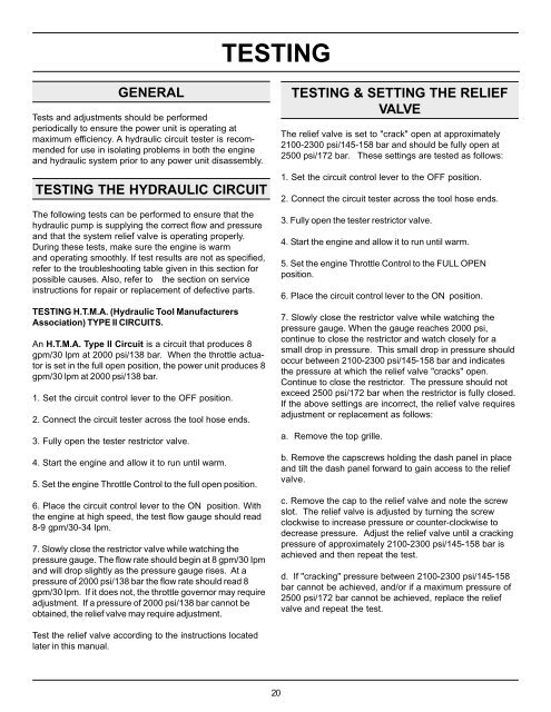
GENERAL<br />
Tests and adjustments should be performed<br />
periodically to ensure the power unit is operating at<br />
maximum efficiency. A hydraulic circuit tester is recommended<br />
for use in isolating problems in both the engine<br />
and hydraulic system prior to any power unit disassembly.<br />
TESTING THE HYDRAULIC CIRCUIT<br />
The following tests can be performed to ensure that the<br />
hydraulic pump is supplying the correct flow and pressure<br />
and that the system relief valve is operating properly.<br />
During these tests, make sure the engine is warm<br />
and operating smoothly. If test results are not as specified,<br />
refer to the troubleshooting table given in this section for<br />
possible causes. Also, refer to the section on service<br />
instructions for repair or replacement of defective parts.<br />
TESTING H.T.M.A. (Hydraulic <strong>Tool</strong> Manufacturers<br />
Association) TYPE II CIRCUITS.<br />
An H.T.M.A. Type II Circuit is a circuit that produces 8<br />
gpm/30 lpm at 2000 psi/138 bar. When the throttle actuator<br />
is set in the full open position, the power unit produces 8<br />
gpm/30 lpm at 2000 psi/138 bar.<br />
1. Set the circuit control lever to the OFF position.<br />
2. Connect the circuit tester across the tool hose ends.<br />
3. Fully open the tester restrictor valve.<br />
4. Start the engine and allow it to run until warm.<br />
5. Set the engine Throttle Control to the full open position.<br />
6. Place the circuit control lever to the ON position. With<br />
the engine at high speed, the test flow gauge should read<br />
8-9 gpm/30-34 lpm.<br />
7. Slowly close the restrictor valve while watching the<br />
pressure gauge. The flow rate should begin at 8 gpm/30 Ipm<br />
and will drop slightly as the pressure gauge rises. At a<br />
pressure of 2000 psi/138 bar the flow rate should read 8<br />
gpm/30 lpm. If it does not, the throttle governor may require<br />
adjustment. If a pressure of 2000 psi/138 bar cannot be<br />
obtained, the relief valve may require adjustment.<br />
Test the relief valve according to the instructions located<br />
later in this manual.<br />
TESTING<br />
20<br />
TESTING & SETTING THE RELIEF<br />
VALVE<br />
The relief valve is set to "crack" open at approximately<br />
2100-2300 psi/145-158 bar and should be fully open at<br />
2500 psi/172 bar. These settings are tested as follows:<br />
1. Set the circuit control lever to the OFF position.<br />
2. Connect the circuit tester across the tool hose ends.<br />
3. Fully open the tester restrictor valve.<br />
4. Start the engine and allow it to run until warm.<br />
5. Set the engine Throttle Control to the FULL OPEN<br />
position.<br />
6. Place the circuit control lever to the ON position.<br />
7. Slowly close the restrictor valve while watching the<br />
pressure gauge. When the gauge reaches 2000 psi,<br />
continue to close the restrictor and watch closely for a<br />
small drop in pressure. This small drop in pressure should<br />
occur between 2100-2300 psi/145-158 bar and indicates<br />
the pressure at which the relief valve "cracks" open.<br />
Continue to close the restrictor. The pressure should not<br />
exceed 2500 psi/172 bar when the restrictor is fully closed.<br />
If the above settings are incorrect, the relief valve requires<br />
adjustment or replacement as follows:<br />
a. Remove the top grille.<br />
b. Remove the capscrews holding the dash panel in place<br />
and tilt the dash panel forward to gain access to the relief<br />
valve.<br />
c. Remove the cap to the relief valve and note the screw<br />
slot. The relief valve is adjusted by turning the screw<br />
clockwise to increase pressure or counter-clockwise to<br />
decrease pressure. Adjust the relief valve until a cracking<br />
pressure of approximately 2100-2300 psi/145-158 bar is<br />
achieved and then repeat the test.<br />
d. If "cracking" pressure between 2100-2300 psi/145-158<br />
bar cannot be achieved, and/or if a maximum pressure of<br />
2500 psi/172 bar cannot be achieved, replace the relief<br />
valve and repeat the test.


