Mobile Hydraulic Power Unit Safety, Operation and ... - Tool-Smith
Mobile Hydraulic Power Unit Safety, Operation and ... - Tool-Smith
Mobile Hydraulic Power Unit Safety, Operation and ... - Tool-Smith
You also want an ePaper? Increase the reach of your titles
YUMPU automatically turns print PDFs into web optimized ePapers that Google loves.
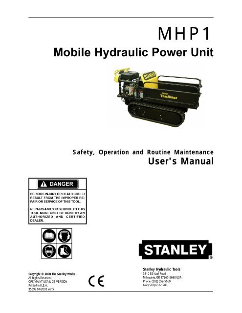
MHP1<br />
<strong>Mobile</strong> <strong>Hydraulic</strong> <strong>Power</strong> <strong>Unit</strong><br />
SERIOUS INJURY OR DEATH COULD<br />
RESULT FROM THE IMPROPER RE-<br />
PAIR OR SERVICE OF THIS TOOL.<br />
REPAIRS AND / OR SERVICE TO THIS<br />
TOOL MUST ONLY BE DONE BY AN<br />
AUTHORIZED AND CERTIFIED<br />
DEALER.<br />
Copyright © 2000 The Stanley Works<br />
All Rights Reserved<br />
OPS/MAINT USA & CE VERSION<br />
Printed in U.S.A.<br />
35599 01/2003 Ver 5<br />
<strong>Safety</strong>, <strong>Operation</strong> <strong>and</strong> Routine Maintenance<br />
User's Manual<br />
Stanley <strong>Hydraulic</strong> <strong>Tool</strong>s<br />
3810 SE Naef Road<br />
Milwaukie, OR 97267-5698 USA<br />
Phone: (503) 659-5660<br />
Fax: (503) 652-1780
1<br />
Accessories ........................................................................................... 17<br />
Disengaging Gear Boxes ........................................................................ 16<br />
<strong>Hydraulic</strong> Hose Requirements .................................................................. 5<br />
<strong>Hydraulic</strong> Hose & Fitting Connections ................................................. 6 - 7<br />
Loading & Unloading........................................................................ 13 - 14<br />
<strong>Operation</strong> .......................................................................................... 8 - 13<br />
Parts Lists....................................................................................... 18 - 23<br />
Routine Maintenance ....................................................................... 14 - 15<br />
<strong>Safety</strong> Precautions ..............................................................................2 - 3<br />
Specifications ......................................................................................... 17<br />
<strong>Tool</strong> Stickers <strong>and</strong> Tags ............................................................................. 4<br />
Transporting ........................................................................................... 14<br />
Troubleshooting ...................................................................................... 16<br />
Warranty ................................................................................................ 25<br />
Wiring Diagram ....................................................................................... 24<br />
CONTENTS<br />
SERVICING THE MHP1: This manual contains safety, operation, <strong>and</strong> routine maintenance instructions.<br />
Stanley <strong>Hydraulic</strong> <strong>Tool</strong>s recommends that servicing of this equipment, other than routine<br />
maintenance, must be performed by an authorized <strong>and</strong> certified dealer. Please read the following<br />
warning.<br />
SERIOUS SERIOUS INJURY INJURY INJURY OR OR DEA DEATH DEA TH COULD COULD RESUL RESULT RESUL T FROM<br />
FROM<br />
THE THE IMPROPER IMPROPER REP REPAIR REP AIR OR OR SERVICE SERVICE OF OF THIS THIS TOOL TOOL. TOOL<br />
REP REPAIRS REP AIRS AND AND / / OR OR SERVICE SERVICE TO TO THIS THIS TOOL TOOL MUST<br />
MUST<br />
ONL ONLY ONL Y BE BE DONE DONE B BBY<br />
B Y AN AN A AAUTHORIZED<br />
A UTHORIZED AND AND CERTIFIED<br />
CERTIFIED<br />
DEALER.<br />
DEALER.<br />
DEALER.
GENERAL SAFETY PRECAUTIONS<br />
<strong>Tool</strong> operators <strong>and</strong> maintenance personnel must always comply with the safety<br />
precautions given in this manual <strong>and</strong> on the stickers <strong>and</strong> tags attached to the<br />
machine.<br />
These safety precautions are given for your safety. Review them carefully before<br />
operating the machine <strong>and</strong> before performing general maintenance or routine<br />
service.<br />
Supervising personnel should develop additional precautions relating to the<br />
specific work area <strong>and</strong> local safety regulations. If so, place the added precautions in<br />
the space provided on page 3.<br />
If you have not read this manual or the engine manual, you are not ready to operate the<br />
MHP1. Read <strong>and</strong> underst<strong>and</strong> this manual <strong>and</strong> any stickers <strong>and</strong> tags attached to the<br />
machine before operation. Failure to do so can result in equipment damage, personal<br />
injury, or death.<br />
• Operate the machine in a work area without byst<strong>and</strong>ers. The operator must be familiar with all prohibited work<br />
areas such as excessive slopes <strong>and</strong> dangerous terrain conditions.<br />
• DO NOT operate the machine ACROSS excessive slopes where "tip over" is a hazard.<br />
• DO NOT operate the machine in confined areas where there may be a risk of crushing the operator between the<br />
machine <strong>and</strong> another object.<br />
• DO NOT operate the machine in enclosed spaces. Inhalation of engine exhaust can be fatal.<br />
• DO NOT wear loose clothing that can get entangled in the working parts of the machine or hydraulic tools.<br />
• DO NOT add fuel to the machine while it is running or still hot.<br />
• DO NOT operate the machine if a fuel odor is present.<br />
• DO NOT operate the machine within 3.3 ft./1 m of buildings, obstructions, or flammable objects.<br />
• Allow the engine to cool before storing the machine in an enclosure.<br />
• DO NOT ride on, or allow anyone else to ride on, the machine at any time.<br />
• Establish a training program for all operators to ensure safe operation.<br />
• DO NOT operate the machine unless thoroughly trained or under the supervision of an instructor.<br />
SAFETY<br />
• Always wear safety equipment such as goggles, ear, head protection, <strong>and</strong> safety shoes at all times when operating<br />
the machine.<br />
• DO NOT inspect or clean the machine while the engine is running. Accidental engagement of the machine can<br />
cause serious injury or death.<br />
• The hydraulic circuit control valve must be in the "OFF"position when coupling or uncoupling hydraulic tools.<br />
2
3<br />
This safety symbol may<br />
appear on the machine. It is<br />
used to alert the operator of<br />
an action that could place<br />
him/her or others in a life<br />
threatening situation.<br />
This safety symbol appears in<br />
these instructions to identify<br />
an action that could cause<br />
bodily injury to the operator or<br />
other personnel.<br />
Always observe safety symbols. They are included for your safety <strong>and</strong> for the protection of the tool.<br />
LOCAL SAFETY REGULATIONS<br />
SAFETY Continued . . .<br />
Wipe all couplers clean before connecting. Use only lint-free cloths. Failure to do so may result in damage to the<br />
quick couplers <strong>and</strong> cause overheating of the hydraulic system.<br />
• Before operating hydraulic tools, read <strong>and</strong> underst<strong>and</strong> the operation manual furnished with the tool.<br />
• DO NOT operate a damaged, or improperly adjusted, machine.<br />
• DO NOT weld or cut with an acetylene torch any surface or component of the equipment. Consult with the<br />
Stanley factory before performing any welding or acetylene cutting of the equipment.<br />
• Prevent possible personal injury or equipment damage by having all repair, maintenance <strong>and</strong> service performed<br />
only by authorized <strong>and</strong> properly trained personnel.<br />
• DO NOT exceed the rated limits of the equipment or use the equipment for applications beyond its design<br />
capacity.<br />
• Always keep critical markings, such as lables <strong>and</strong> warning stickers legible.<br />
• Always replace parts with replacement parts recommended by Stanley <strong>Hydraulic</strong> <strong>Tool</strong>s.<br />
SAFETY SYMBOLS<br />
<strong>Safety</strong> symbols are used to emphasize all operator, maintenance <strong>and</strong> repair actions which, if not strictly followed,<br />
could result in a life-threatening situation, bodily injury or damage to equipment.<br />
This safety symbol appears in<br />
these instructions to identify<br />
an action or condition that<br />
could result in damage to the<br />
tool or other equipment.<br />
Enter any local safety regulations here. Keep these instructions in an area accessible to the operator <strong>and</strong> maintenance<br />
personnel.
Dual Circuit Valve Block<br />
Decal P/N-28045<br />
Caution Decal P/N-28089<br />
Choke Decal P/N-07764<br />
<strong>Hydraulic</strong> Fluid Decal<br />
P/N-35686<br />
Lift Location Decal<br />
P/N-59045<br />
The safety tag (p/n 15875)<br />
at right is attached to the<br />
machine when shipped<br />
from the factory. Read <strong>and</strong><br />
underst<strong>and</strong> the safety<br />
instructions listed on this<br />
tag before removal. We<br />
suggest you retain this tag<br />
<strong>and</strong> attach it to the<br />
machine when not in use.<br />
Lift Location Decal<br />
P/N-59045<br />
<strong>Hydraulic</strong> Fluid<br />
Decal P/N-35686<br />
Limit Engine Speed<br />
Decal P/N-59044<br />
Gas Throttle Decal<br />
P/N-59043<br />
Start-Up Decal<br />
P/N-59041 (Dual Circuit)<br />
P/N-59042 (Single Circuit)<br />
DANGER<br />
Stanley Decal<br />
P/N-05154<br />
Start-Up Decal P/N 59042<br />
(Single Circuit)<br />
1. FAILURE TO USE HYDRAULIC HOSE LABELED AND CERTIFIED<br />
AS NON-CONDUCTIVE WHEN USING HYDRAULIC TOOLS ON<br />
OR NEAR ELECTRICAL LINES MAY RESULT IN DEATH OR SERI-<br />
OUS INJURY.<br />
BEFORE USING HOSE LABELED AND CERTIFIED AS NON-CON-<br />
DUCTIVE ON OR NEAR ELECTRIC LINES BE SURE THE HOSE IS<br />
MAINTAINED AS NON-CONDUCTIVE. THE HOSE SHOULD BE<br />
REGULARLY TESTED FOR ELECTRIC CURRENT LEAKAGE IN<br />
ACCORDANCE WITH YOUR SAFETY DEPARTMENT INSTRUC-<br />
TIONS.<br />
2. A HYDRAULIC LEAK OR BURST MAY CAUSE OIL INJECTION<br />
INTO THE BODY OR CAUSE OTHER SEVERE PERSONAL INJURY.<br />
A DO NOT EXCEED SPECIFIED FLOW AND PRESSURE FOR<br />
THIS TOOL. EXCESS FLOW OR PRESSURE MAY CAUSE A<br />
LEAK OR BURST.<br />
B DO NOT EXCEED RATED WORKING PRESSURE OF HYDRAU<br />
LIC HOSE USED WITH THIS TOOL. EXCESS PRESSURE MAY<br />
CAUSE A LEAK OR BURST.<br />
C CHECK TOOL HOSE COUPLERS AND CONNECTORS DAILY<br />
FOR LEAKS. DO NOT FEEL FOR LEAKS WITH YOUR HANDS.<br />
CONTACT WITH A LEAK MAY RESULT IN SEVERE PERSONAL<br />
INJURY.<br />
IMPORTANT<br />
READ OPERATION MANUAL AND<br />
SAFETY INSTRUCTIONS FOR THIS<br />
TOOL BEFORE USING IT.<br />
USE ONLY PARTS AND REPAIR<br />
PROCEDURES APPROVED BY<br />
STANLEY AND DESCRIBED IN THE<br />
OPERATION MANUAL.<br />
TAG TO BE REMOVED ONLY BY<br />
TOOL OPERATOR.<br />
SEE OTHER SIDE<br />
SAFETY TAG P/N 15875 (shown smaller then actual size)<br />
TOOL STICKERS & TAGS<br />
TracHorse Decal<br />
P/N-59046<br />
Choke Decal P/N-07764<br />
Caution Decal P/N-28089<br />
Start-Up Decal P/N 59041<br />
(Dual Circuit)<br />
DANGER<br />
D DO NOT LIFT OR CARRY TOOL BY THE HOSES. DO NOT<br />
ABUSE HOSE. DO NOT USE KINKED, TORN OR DAMAGED<br />
HOSE.<br />
3. MAKE SURE HYDRAULIC HOSES ARE PROPERLY CONNECTED<br />
TO THE TOOL BEFORE PRESSURING SYSTEM. SYSTEM PRES-<br />
SURE HOSE MUST ALWAYS BE CONNECTED TO TOOL "IN" PORT.<br />
SYSTEM RETURN HOSE MUST ALWAYS BE CONNECTED TO TOOL<br />
"OUT" PORT. REVERSING CONNECTIONS MAY CAUSE REVERSE<br />
TOOL OPERATION WHICH CAN RESULT IN SEVERE PERSONAL<br />
INJURY.<br />
4. DO NOT CONNECT OPEN-CENTER TOOLS TO CLOSED-CENTER<br />
HYDRAULIC SYSTEMS. THIS MAY RESULT IN LOSS OF OTHER<br />
HYDRAULIC FUNCTIONS POWERED BY THE SAME SYSTEM AND/<br />
OR SEVERE PERSONAL INJURY.<br />
5. BYSTANDERS MAY BE INJURED IN YOUR WORK AREA. KEEP BY-<br />
STANDERS CLEAR OF YOUR WORK AREA.<br />
6. WEAR HEARING, EYE, FOOT, HAND AND HEAD PROTECTION.<br />
7. TO AVOID PERSONAL INJURY OR EQUIPMENT DAMAGE, ALL TOOL<br />
REPAIR MAINTENANCE AND SERVICE MUST ONLY BE PER-<br />
FORMED BY AUTHORIZED AND PROPERLY TRAINED PERSON-<br />
NEL.<br />
IMPORTANT<br />
TracHorse Decal<br />
P/N-59046<br />
Lift Location Decal<br />
P/N-59045<br />
TracHorse Decal<br />
P/N-59046<br />
Dual Circuit Valve block<br />
Decal P/N-28045<br />
READ OPERATION MANUAL AND<br />
SAFETY INSTRUCTIONS FOR THIS<br />
TOOL BEFORE USING IT.<br />
USE ONLY PARTS AND REPAIR<br />
PROCEDURES APPROVED BY<br />
STANLEY AND DESCRIBED IN THE<br />
OPERATION MANUAL.<br />
TAG TO BE REMOVED ONLY BY<br />
TOOL OPERATOR.<br />
SEE OTHER SIDE<br />
15875 15875<br />
4
HOSE TYPES<br />
<strong>Hydraulic</strong> hose types authorized for use with Stanley <strong>Hydraulic</strong> <strong>Tool</strong>s are as follows:<br />
DO NOT REMOVE THIS<br />
TAG<br />
➊ Certified non-conductive<br />
➋ Wire-braided (conductive)<br />
➌ Fabric-braided (not certified or labeled non-conductive)<br />
Hose ➊ listed above is the only hose authorized for use near electrical conductors.<br />
Hoses ➋ <strong>and</strong> ➌ listed above are conductive <strong>and</strong> must never be used near electrical conductors.<br />
HOSE SAFETY TAGS<br />
To help ensure your safety, the following DANGER tags are attached to all hose purchased from Stanley <strong>Hydraulic</strong><br />
<strong>Tool</strong>s. DO NOT REMOVE THESE TAGS.<br />
If the information on a tag is illegible because of wear or damage, replace the tag immediately. A new tag may be<br />
obtained at no charge from your Stanley Distributor.<br />
DO NOT REMOVE THIS<br />
TAG<br />
D A N G E R<br />
1 FAILURE TO USE HYDRAULIC HOSE LABELED AND CERTIFIED AS NON-CONDUCTIVE WHEN<br />
USING HYDRAULIC TOOLS ON OR NEAR ELECTRIC LINES MAYRESULT IN DEATH OR SERIOUS<br />
INJURY.<br />
FOR PROPER AND SAFE OPERATION MAKE SURE THAT YOU HAVE BEEN PROPERLY TRAINED IN<br />
CORRECT PROCEDURES REQUIRED FOR WORK ON OR AROUND ELECTRIC LINES.<br />
2. BEFORE USING HYDRAULIC HOSE LABELED AND CERTIFIED AS NON-CONDUCTIVE ON OR<br />
NEAR ELECTRIC LINES. WIPE THE ENTIRE LENGTH OF THE HOSE AND FITTING WITH A CLEAN<br />
DRY ABSORBENT CLOTH TO REMOVE DIRT AND MOSISTURE AND TEST HOSE FOR MAXIMUM<br />
ALLOWABLE CURRENT LEAKAGE IN ACCORDANCE WITH SAFETY DEPARTMENT<br />
INSTRUCTIONS.<br />
SEE OTHER SIDE<br />
D A N G E R<br />
3. DO NOT EXCEED HOSE WORKING PRESSURE OR ABUSE HOSE. IMPROPER USE OR HANDLING<br />
OF HOSE COULD RESULT IN BURST OR OTHER HOSE FAILURE. KEEP HOSE AS FAR AWAY AS<br />
POSSIBLE FROM BODY AND DO NOT PERMIT DIRECT CONTACT DURING USE. CONTACT AT THE<br />
BURST CAN CAUSE BODILY INJECTION AND SEVERE PERSONAL INJURY.<br />
4. HANDLE AND ROUTE HOSE CAREFULLY TO AVOID KINKING, ABRASION, CUTTING, OR CONTACT<br />
WITH HIGH TEMPERATURE SURFACES. DO NOT USE IF KINKED. DO NOT USE HOSE TO PULL OR<br />
LIFT TOOLS, POWER UNITS, ETC.<br />
5. CHECK ENTIRE HOSE FOR CUTS CRACKS LEAKS ABRASIONS, BULGES, OR DAMAGE TO<br />
COUPLINGS IF ANY OF THESE CONDITIONS EXIST, REPLACE THE HOSE IMMEDIATELY. NEVER<br />
USE TAPE OR ANY DEVICE TO ATTEMPT TO MEND THE HOSE.<br />
6. AFTER EACH USE STORE IN A CLEAN DRY AREA.<br />
SEE OTHER SIDE<br />
3 SIDE 1 (shown smaller than actual size)<br />
SIDE 2<br />
D A N G E R<br />
1 DO NOT USE THIS HYDRAULIC HOSE ON OR NEAR ELECTRIC LINES. THIS HOSE IS NOT<br />
LABELED OR CERTIFIED AS NON-CONDUCTIVE. USING THIS HOSE ON OR NEAR ELECTRICAL<br />
LINES MAY RESULT IN DEATH OR SERIOUS INJURY.<br />
2. FOR PROPER AND SAFE OPERATION MAKE SURE THAT YOU HAVE BEEN PROPERLY TRAINED IN<br />
CORRECT PROCEDURES REQUIRED FOR WORK ON OR AROUND ELECTRIC LINES.<br />
3. DO NOT EXCEED HOSE WORKING PRESSURE OR ABUSE HOSE. IMPROPER USE OR HANDLING<br />
OF HOSE COULD RESULT IN BURST OR OTHER HOSE FAILURE. KEEP HOSE AS FAR AWAY AS<br />
POSSIBLE FROM BODY AND DO NOT PERMIT DIRECT CONTACT DURING USE. CONTACT AT<br />
THE BURST CAN CAUSE BODILY INJECTION AND SEVERE PERSONAL INJURY.<br />
4. HANDLE AND ROUTE HOSE CAREFULLY TO AVOID KINKING, CUTTING, OR CONTACT WITH<br />
HIGH TEMPERATURE SURFACES. DO NOT USE IF KINKED. DO NOT USE HOSE TO PULL OR LIFT<br />
TOOLS, POWER UNITS, ETC.<br />
SEE OTHER SIDE<br />
HOSE PRESSURE RATING<br />
TOOL CIRCUIT HYDRAULIC HOSE REQUIREMENTS<br />
The tag shown below is attached to "certified non-conductive" hose.<br />
The tag shown below is attached to "conductive" hose.<br />
D A N G E R<br />
5. CHECK ENTIRE HOSE FOR CUTS CRACKS LEAKS ABRASIONS, BULGES, OR DAMAGE TO<br />
COUPLINGS IF ANY OF THESE CONDITIONS EXIST, REPLACE THE HOSE IMMEDIATELY. NEVER<br />
USE TAPE OR ANY DEVICE TO ATTEMPT TO MEND THE HOSE.<br />
6. AFTER EACH USE STORE IN A CLEAN DRY AREA.<br />
SEE OTHER SIDE<br />
SIDE 1 (shown smaller than actual size)<br />
SIDE 2<br />
The rated working pressure of the hydraulic hose must be equal to or higher than the relief valve setting on the hydraulic<br />
system.<br />
5<br />
DO NOT REMOVE THIS<br />
TAG<br />
DO NOT REMOVE THIS<br />
TAG
HOSE & FITTING CONNECTIONS for SINGLE CIRCUIT<br />
ADAPTER, 1/2 INCH MALE PIPE x -10 SAE O-RING<br />
(STANLEY P/N 07882 ADAPTER)<br />
H.T.M.A. 1/2 INCH FEMALE QUICK DISCONNECT COUPLER<br />
(STANLEY P/N 24060 COUPLER BODY or STANLEY P/N<br />
03974 COUPLER SET - nose & body)<br />
H.T.M.A. 1/2 INCH MALE QUICK DISCONNECT COUPLER<br />
(STANLEY P/N 24061 COUPLER NOSE or STANLEY P/N<br />
03974 COUPLER SET - nose & body)<br />
31972 Assy w/couplers.<br />
31848 Hose Assy w/couplers<br />
1/2 INCH I.D. HOSE, 25 FT TO 50 FT LONG.<br />
(FOR 25 FEET, STANLEY P/N 04972 HYDRAULIC HOSE or<br />
STANLEY P/N 05009 DUAL HYDRAULIC HOSES)<br />
(FOR 50 FEET, STANLEY P/N 04978 HYDRAULIC HOSE or<br />
STANLEY P/N 05008 DUAL HYDRAULIC HOSES)<br />
1/2 INCH MALE PIPE HOSE END<br />
H.T.M.A. 1/2 INCH FEMALE QUICK DISCONNECT COUPLER<br />
(STANLEY P/N 24060 COUPLER BODY or STANLEY P/N<br />
03974 COUPLER SET - nose & body)<br />
H.T.M.A. 1/2 INCH MALE QUICK DISCONNECT COUPLER<br />
(STANLEY P/N 24061 COUPLER NOSE or STANLEY P/N<br />
03974 COUPLER SET - nose & body)<br />
ADAPTER, 3/8 INCH MALE PIPE x -8 SAE O-RING<br />
(STANLEY P/N 00936 ADAPTER) NOTE: ADAPTERS<br />
OR HOSE WHIPS ARE INCLUDED WITH TOOLS.<br />
6
7<br />
CONTROL<br />
LEVER<br />
HOSE & FITTING CONNECTIONS for DUAL CIRCUIT<br />
VALVE BLOCK<br />
TOOL COU-<br />
PLERS<br />
H.T.M.A. 1/2 INCH MALE QUICK DISCONNECT COUPLER<br />
(STANLEY P/N 24061 COUPLER NOSE or STANLEY P/N<br />
03974 or 24070COUPLER SET - nose & body)<br />
H.T.M.A. 1/2 INCH FEMALE QUICK DISCONNECT COUPLER<br />
(STANLEY P/N 24060 COUPLER BODY or STANLEY P/N<br />
03974 or 24070 COUPLER SET - nose & body)<br />
1/2 INCH I.D. HOSE, 25 FT TO 50 FT LONG.<br />
(FOR 25 FEET, STANLEY P/N 04978 HYDRAULIC HOSE or<br />
STANLEY P/N 05008 DUAL HYDRAULIC HOSES)<br />
(FOR 50 FEET, STANLEY P/N 04979 HYDRAULIC HOSE or<br />
STANLEY P/N 05009 DUAL HYDRAULIC HOSES)<br />
1/2 INCH MALE PIPE HOSE END<br />
H.T.M.A. 1/2 INCH MALE QUICK DISCONNECT COUPLER<br />
(STANLEY P/N 24061 COUPLER NOSE or STANLEY P/N<br />
03974 or 24070 COUPLER SET - nose & body)<br />
H.T.M.A. 1/2 INCH FEMALE QUICK DISCONNECT COUPLER<br />
(STANLEY P/N 24060 COUPLER BODY or STANLEY P/N<br />
03974 COUPLER SET - nose & body)<br />
ADAPTER, 3/8 INCH MALE PIPE x -8 SAE O-RING<br />
(STANLEY P/N 00936 ADAPTER) NOTE: ADAPTERS<br />
OR HOSE WHIPS ARE INCLUDED WITH TOOLS.
PREOPERATION<br />
PROCEDURES<br />
Preparation For Initial Use<br />
The equipment, as shipped, has no special unpacking or<br />
assembly requirements prior to usage. Inspection to<br />
assure the equipment was not damaged in shipping,<br />
does not contain packing debris, <strong>and</strong> checking fluid<br />
levels as described below, is all that is required.<br />
Engine Oil Level<br />
Before each use, check the engine oil level. Make<br />
sure the engine oil level is at the FULL MARK on<br />
the dipstick. Do not overfill. Use detergent oil<br />
classified "For Service SE, SF, SG" as specified in the<br />
engine operating <strong>and</strong> maintenance manual.<br />
The engine oil dipstick is located on the right side of<br />
the engine for both the Honda <strong>and</strong> B & S engines.<br />
Engine Oil<br />
Filler Cap<br />
Engine Oil<br />
Dipstick<br />
Engine Oil<br />
Filler Cap<br />
HONDA ENGINE<br />
Engine Oil<br />
Dipstick<br />
BRIGGS & STRATTON<br />
ENGINE<br />
Engine Fuel Level<br />
Check the fuel level. If low, fill with unleaded<br />
gasoline with a minimum of 85 octane rating.<br />
Warning Lights<br />
Engine Oil<br />
OPERATING INSTRUCTIONS<br />
A warning light is located on the instrument panel<br />
near the ignition key. The light comes on when the<br />
ignition key is turned to the "ON" position. After the<br />
engine is started, the light should turn off. If the light<br />
stays on, the engine oil is low. Shut down the engine<br />
immediately <strong>and</strong> check the engine oil level. Add oil<br />
as required.<br />
<strong>Hydraulic</strong> Fluid<br />
Low Engine Oil<br />
Warning Light<br />
A warning light is located on the instrument panel<br />
near the ignition key. The light DOES NOT COME<br />
ON when the ignition key is turned to the "ON"<br />
position unless the hydraulic fluid level is too low. If<br />
the hydraulic fluid level is too low, the light will stay<br />
on after the engine has been started. Shut down the<br />
engine immediately <strong>and</strong> add hydraulic fluid as<br />
required. When the hydraulic fluid level is correct,<br />
the light should not be on.<br />
Low<strong>Hydraulic</strong><br />
Fluid Warning<br />
Light<br />
Low hydraulic fluid indicates a leak in the hydraulic<br />
system. Inspect all hydraulic connections<br />
<strong>and</strong> hydraulic components for leaks.<br />
DO NOT use the equipment until leaks are<br />
repaired.<br />
8
OPERATION<br />
Location of Instruments, Switches, <strong>and</strong><br />
Controls<br />
NOTE: Use caution when operating or ordering items 3 & 7 they<br />
can come installed oppisite of what is illustrated above. The<br />
Bed up/down switch is spring loaded <strong>and</strong> will return to the<br />
center position when released. The tool ciucuit on/off switch<br />
is either on or off (2 way) no center position.<br />
9<br />
5<br />
1. Left & Right Track Controls for Forward, Reverse,<br />
<strong>and</strong> Left, Right Steering<br />
2. Throttle<br />
3. <strong>Tool</strong> Circuit ON/OFF Switch<br />
4. Hour Meter<br />
5. Key Ignition<br />
6. Warning Lights<br />
7. Bed UP/DOWN Switch<br />
8. Choke<br />
9. <strong>Tool</strong> Circuit Controls<br />
10. Fuel Shutoff<br />
Starting The Engine<br />
4<br />
1. Ensure the tool circuit control lever(s) are in the OFF<br />
position <strong>and</strong> the tool circuit switch is in the OFF<br />
position.<br />
2. Pull the choke out until it stops.<br />
1<br />
7<br />
10<br />
3. Move the throttle to a position between "SLOW"<br />
<strong>and</strong> "FAST".<br />
4. Turn the ignition key clockwise to begin cranking<br />
the engine. Use short starting cycles (15 seconds per<br />
minute) to prolong starter life. Extended cranking can<br />
2<br />
3<br />
8<br />
6 9<br />
damage the starter motor.<br />
5. After the engine starts, allow it to warm-up for a few<br />
seconds before moving the choke. Move the choke<br />
inward in small steps to allow the engine to accept<br />
small changes in speed <strong>and</strong> load. Continue moving<br />
the choke in until it is fully off <strong>and</strong> the engine is<br />
running smoothly.<br />
6. Adjust the throttle for the work to be done. See<br />
"Adjusting Throttle For Various Types of Work".<br />
Stopping The Engine<br />
1. Move the throttle to the "SLOW" position.<br />
2. Ensure the tool circuit control lever(s) are in the OFF<br />
position <strong>and</strong> the tool circuit switch is in the "OFF"<br />
position.<br />
3. Turn the ignition key counter clockwise to the<br />
"OFF" position.<br />
Adjusting Throttle for Various Types of<br />
Work<br />
Forward Travel<br />
The throttle can be positioned anywhere between<br />
"SLOW" <strong>and</strong> "FAST" for traveling forward depending<br />
on the weight of the load being carried. Heavy<br />
loads will require higher throttle settings in order for<br />
the engine to provide enough power to move the<br />
load.<br />
Reverse Travel<br />
Position the throttle to "SLOW" for reverse travel to<br />
permit increased control <strong>and</strong> safety.<br />
DO NOT attempt to travel in reverse with the<br />
throttle positioned above "SLOW". This may<br />
result in loss of control <strong>and</strong> result in injury<br />
or death to the operator.<br />
Bed Cylinder<br />
The throttle may be positioned anywhere between<br />
"SLOW" <strong>and</strong> "FAST" when operating the bed.<br />
<strong>Tool</strong> Circuit<br />
The throttle must be positioned to "FAST" when<br />
using the tool circuit. Slower throttle settings will<br />
stall the engine or provide reduced oil flow.
Slope <strong>Operation</strong><br />
DO NOT operate the machine on slopes exceeding 60<br />
degrees in the travel direction or across slopes<br />
exceeding 45 degrees..<br />
Avoid turning on slopes. If you must turn, turn<br />
slowly downhill, if possible.<br />
DO NOT operate the machine near drop-offs,<br />
ditches, or embankments. The machine could<br />
suddenly turn over if a track goes over the edge or if<br />
an edge collapses.<br />
DO NOT try to stabilize the machine if it is tipping<br />
over. Let go of the machine <strong>and</strong> get out of its way.<br />
Traveling Forward or Reverse<br />
When first learning to operate the Track<br />
Horse, position the throttle to the "SLOW"<br />
position. More experienced operators<br />
may use higher throttle settings.<br />
Track Steering Controls<br />
To travel forward, reverse, turn left, or turn right, do<br />
the following:<br />
Forward Travel<br />
TO MOVE FORWARD IN A STRAIGHT LINE: Move<br />
both the left <strong>and</strong> right track controls forward at the<br />
same time.<br />
TO TRAVEL FORWARD<br />
Move Both Controls<br />
Forward<br />
TO TURN LEFT WHILE MOVING FORWARD:<br />
Release the left track control while pushing forward<br />
on the right track control. Resume pushing forward<br />
on the left track control to move forward in a straight<br />
line.<br />
TO TURN LEFT WHILE<br />
MOVING FORWARD<br />
Release left control<br />
while holding right<br />
control forward<br />
TO TURN RIGHT WHILE MOVING FORWARD:<br />
Release the right track control while pushing forward<br />
on the left track control. Resume pushing forward on<br />
the right track control to move forward in a straight<br />
line.<br />
TO TURN RIGHT WHILE<br />
MOVING FORWARD<br />
Release right control<br />
while holding left<br />
control forward<br />
10
Reverse Travel<br />
11<br />
DO NOT attempt to travel in reverse with the<br />
throttle positioned above "SLOW". This may<br />
result in loss of control <strong>and</strong> result in injury<br />
or death to the operator.<br />
TO MOVE BACKWARDS IN A STRAIGHT LINE:<br />
Move both the left <strong>and</strong> right track controls backward<br />
at the same time.<br />
TO TRAVEL BACK-<br />
WARD<br />
Move Both Controls<br />
Backward<br />
TO TURN LEFT WHILE MOVING BACKWARD:<br />
Release the left track control while pulling backward<br />
on the right track control. Resume pulling backward<br />
on the left track control to move backward in a<br />
straight line.<br />
TO TURN LEFT WHILE<br />
MOVING BACKWARD<br />
Release left control<br />
while holding right<br />
control backward<br />
TO TURN RIGHT WHILE MOVING BACKWARD:<br />
Release the right track control while pulling backward<br />
on the left track control. Resume pulling<br />
backward on the right track control to move backward<br />
in a straight line.<br />
Turning From A Stop<br />
TO TURN RIGHT WHILE<br />
MOVING BACKWARD<br />
Release right control<br />
while holding left<br />
control backward<br />
TO TURN LEFT FROM A STOP: Move the right track<br />
control forward <strong>and</strong> the left track control backward.<br />
TO TURN LEFT<br />
FROM A STOP<br />
Move the right<br />
control forward<br />
<strong>and</strong> the left control<br />
backward<br />
TO TURN RIGHT FROM A STOP: Move the left<br />
track control forward <strong>and</strong> the right track control<br />
backward.<br />
TO TURN RIGHT<br />
FROM A STOP<br />
Move the<br />
leftcontrol forward<br />
<strong>and</strong> the right<br />
control backward
Bed <strong>Operation</strong><br />
1. Adjust the throttle to a "SLOW" to "MEDIUM"<br />
setting.<br />
2. Press the rocker switch on the instrument panel to<br />
raise or lower the bed.<br />
Ensure the tailgate has been removed before<br />
lifting the dump bed. This will prevent loaded<br />
material from staying in the dump bed which<br />
may cause the equipment to become unstable.<br />
<strong>Hydraulic</strong> <strong>Tool</strong> <strong>Operation</strong><br />
Single <strong>Tool</strong> Circuit (model MHP11111000)<br />
The single tool circuit found on the TracHorse model<br />
MHP11111000 produces 8 gpm/30 lpm with pressure<br />
up to 2000 psi/140 bar.<br />
3 2<br />
Single <strong>Tool</strong> Circuit on model MHP11111000<br />
Above illustration shown in the OFF position<br />
1. ON/OFF Control<br />
2. Male Coupler (Pressure)<br />
3. Female Coupler (Return)<br />
1<br />
Using The <strong>Tool</strong> Circuit<br />
1. Ensure the tool circuit ON/OFF switch located on the<br />
instrument panel is in the "OFF" position <strong>and</strong> the<br />
throttle is in the "SLOW" position.<br />
2. Connect hydraulic hoses from the tool to the<br />
pressure <strong>and</strong> return couplers of the tool circuit.<br />
The recommended hose length to use with hydraulic<br />
tools is 25 ft/8 mm with a 1/2 inch/12.7 mm inside<br />
diameter. See the pages covering hydraulic hose<br />
requirements <strong>and</strong> connections found earlier in this<br />
manual.<br />
3. Adjust the throttle to the "FAST" position.<br />
4. Press the tool circuit ON/OFF switch to the "ON"<br />
position.<br />
5. Activate the tool circuit by moving the ON/OFF<br />
control lever to the right.<br />
6. When finished using the tool, move the control lever<br />
to the left, press the tool circuit ON/OFF switch to<br />
the "OFF" position, <strong>and</strong> move the throttle to the<br />
"SLOW" position.<br />
Before disconnecting hydraulic tools, ensure<br />
the tool circuit control lever is in the "OFF"<br />
position <strong>and</strong> the throttle is in the "SLOW" position.<br />
Dual <strong>Tool</strong> Circuit (model MHP12211000)<br />
The dual tool circuit found on the TracHorse model<br />
MHP12211000 provides two hydraulic tool circuits,<br />
each with an oil flow of 5 gpm/19 lpm with pressure<br />
up to 2000 psi/140 bar. The two circuits may be<br />
combined into one circuit providing 10 gpm/38 lpm<br />
<strong>and</strong> pressure up to 2000 psi/140 bar.<br />
12
13<br />
2<br />
1<br />
3 6<br />
Dual <strong>Tool</strong> Circuit on model MHP12211000<br />
Above illustration shown in the OFF position<br />
1. ON/OFF Control, Left <strong>Tool</strong> Circuit<br />
2. Male Coupler (Pressure), Left <strong>Tool</strong> Circuit<br />
3. Female Coupler (Return), Left <strong>Tool</strong> Circuit<br />
4. ON/OFF Control, Right <strong>Tool</strong> Circuit<br />
5. Male Coupler (Pressure), Right <strong>Tool</strong> Circuit<br />
6. Female Coupler (Return), Right <strong>Tool</strong> Circuit<br />
7. Circuit Combiner Knob<br />
Using 1 or 2 <strong>Tool</strong> Circuits at 5 gpm/19 lpm<br />
1. Ensure the tool circuit ON/OFF switch located on the<br />
instrument panel is in the "OFF" position <strong>and</strong> the<br />
throttle is in the "SLOW" position.<br />
2. Push the circuit combiner knob "IN".<br />
When the circuit combiner knob is pushed in, either<br />
the left, right, or both circuits may be used. When<br />
the circuit combiner knob is pulled out, the two<br />
circuits are combined into one 10 gpm/38 lpm circuit<br />
but only one circuit may be used.<br />
3. If using only one tool, connect hydraulic hoses from<br />
the tool to the pressure <strong>and</strong> return couplers of either<br />
the left or right circuit. If using two tools connect<br />
hydraulic hoses from each tool to the pressure <strong>and</strong><br />
return couplers of each circuit.<br />
The recommended hose length to use with hydraulic<br />
tools is 25 ft/8 mm with a 1/2 inch/12.7 mm inside<br />
diameter. See the pages covering hydraulic hose<br />
requirements <strong>and</strong> connections found earlier in this<br />
manual.<br />
4. Adjust the throttle to the "FAST" position.<br />
4<br />
7<br />
5<br />
5. Press the tool circuit ON/OFF switch to the "ON"<br />
position.<br />
6. Activate each tool circuit by moving the control<br />
lever up. If only one tool is connected, activate that<br />
circuit only.<br />
7. When finished using the tool or tools, move the<br />
control lever(s) down, press the tool circuit ON/OFF<br />
switch to the "OFF" position, <strong>and</strong> move the throttle<br />
to the "SLOW" position.<br />
Before disconnecting hydraulic tools, ensure<br />
the tool circuit control levers are in the down<br />
position <strong>and</strong> the throttle is in the "SLOW" position.<br />
Using 1 <strong>Tool</strong> Circuit at 10 gpm/38 lpm<br />
1. Ensure the tool circuit ON/OFF switch located on the<br />
instrument panel is in the "OFF" position <strong>and</strong> the<br />
throttle is in the "SLOW" position.<br />
2. Pull the circuit combiner knob "OUT".<br />
3. Connect hydraulic hoses from the tool to the<br />
pressure <strong>and</strong> return couplers of either the left or right<br />
circuit. The other circuit must not have a tool<br />
connected to it or have the hoses connected from<br />
the pressure <strong>and</strong> return couplers. DO NOT cross<br />
from one circuit to the other.<br />
4. Adjust the throttle to the "FAST" position.<br />
5. Press the tool circuit ON/OFF switch to the "ON"<br />
position.<br />
6. Activate the tool circuit by moving both control<br />
levers up.<br />
7. When finished using the tool, move the control<br />
levers down, press the tool circuit ON/OFF switch to<br />
the "OFF" position, <strong>and</strong> move the throttle to the<br />
"SLOW" position.
Before disconnecting hydraulic tools, ensure<br />
the tool circuit control levers are in the down<br />
position <strong>and</strong> the throttle is in the "SLOW" position.<br />
COLD WEATHER OPERATION<br />
Fluids are thicker in cold weather, therefore, it is recommended<br />
that the engine be run at low idle long enough to<br />
warm the engine <strong>and</strong> bring the hydraulic system temperature<br />
to a minimum of 50°F/10°C.<br />
If hydraulic tools <strong>and</strong> hoses are to be used, it is recommended<br />
to allow hydraulic fluid to circulate through the<br />
tools <strong>and</strong> hoses until warm before use.<br />
LOADING AND UNLOADING<br />
1. Use loading ramps or a loading dock to load <strong>and</strong><br />
unload the machine. Ensure loading ramps are strong<br />
enough to support the load. When using ramps, do<br />
not exceed a 15 degree incline.<br />
Loading <strong>and</strong> unloading of any type of machine<br />
is dangerous. Never attempt to load or unload<br />
the machine without loading ramps or a loading<br />
dock. Loading ramps must be strong<br />
enough, have a low angle, <strong>and</strong> correct height.<br />
Load <strong>and</strong> unload the machine on a level surface.<br />
Never attempt to load or unload the machine<br />
if the ramp incline exceeds 15 degrees.<br />
Failure to follow these instructions may result<br />
in serious injury or death.<br />
2. Ensure the wheels of the trailer <strong>and</strong> the tow vehicle<br />
have been chocked front <strong>and</strong> rear.<br />
3. Use the "SLOW" throttle setting when loading or<br />
unloading.<br />
4. Drive the machine onto the trailer backwards (engine<br />
first). This will help prevent instability <strong>and</strong> keeps the<br />
operator "up hill" from the machine during loading<br />
<strong>and</strong> unloading.<br />
5. After loading, place chocks at the front <strong>and</strong> rear of<br />
the tracks.<br />
TRANSPORTING<br />
1. Read the instructions for loading <strong>and</strong> unloading in<br />
this section.<br />
2. Use chains <strong>and</strong> binders to secure the load to the<br />
trailer.<br />
ROUTINE MAINTENANCE<br />
Good maintenance practices will keep the machine on the<br />
job <strong>and</strong> increase its service life.<br />
A very important maintenance practice is to keep the<br />
hydraulic fluid clean at all times. Contaminated hydraulic<br />
fluid causes rapid wear <strong>and</strong>/or failure of internal parts.<br />
Follow the maintenance instructions contained in the<br />
engine manual.<br />
Engine Maintenance<br />
Follow the maintenance schedule <strong>and</strong> general maintenance<br />
instructions in the engine maintenance <strong>and</strong><br />
operation manual furnished with the power unit. Normal<br />
maintenance includes:<br />
• Service foam air pre-cleaner every 25 hours of<br />
operation.<br />
• Service air paper cartridge every 100 hours of<br />
operation.<br />
• Replace in-line fuel filter every 100-300 hours or<br />
sooner if required.<br />
• Replace spark plugs every 100 hours of operation.<br />
• Change engine oil after first 5 hours of operation,<br />
then after every 50 hours of operation. If engine has<br />
been operating under heavy load or in high ambient<br />
temperature, change the oil every 25 hours of<br />
operation.<br />
• Change oil filter when engine oil is changed.<br />
• Check oil level daily.<br />
• Remove dirt <strong>and</strong> debris from engine with a cloth or<br />
brush daily. Do not use water spray.<br />
• Clean air cooling system every 100 hours of operation.<br />
14
<strong>Hydraulic</strong> System Maintenance<br />
Observe the following for maximum performance <strong>and</strong><br />
service life from the hydraulic system.<br />
• Always keep hydraulic system <strong>and</strong> fluids clean.<br />
• Keep water out of fluid. (See paragraph b. below.)<br />
• Keep air out of hydraulic lines. <strong>Hydraulic</strong> system<br />
overheating <strong>and</strong> foam at the hydraulic tank breather<br />
indicate air is present in the lines. Keep all suction<br />
line fittings <strong>and</strong> clamps tight.<br />
• <strong>Hydraulic</strong> system wear is noted by increased heat<br />
during tool operation, reduced tool performance <strong>and</strong><br />
eventual system breakdown.<br />
• Operate with the fluid temperature at 50 - 140 F/10 -<br />
60 C for improved seal <strong>and</strong> hose life, <strong>and</strong> maximum<br />
efficiency.<br />
a. Filling The Reservoir<br />
Make sure the engine is stopped before opening the<br />
fillerr cap. Fill slowly with the recommended fluid.<br />
Add fluid as needed. Secure the filler cap before<br />
restarting the engine. Refer to page # 8 (hydraulic fluid)<br />
section for determining correct fluid level.<br />
b. Removing Condensed Moisture From <strong>Hydraulic</strong> Fluid<br />
Condensation is a frequent problem with cool mobile<br />
hydraulic circuits. This condition occurs in moist or<br />
cold climates. When warm air in the hydraulic tank<br />
draws moisture from the cooler air outside, water<br />
accumulates in the tank.<br />
• Allow the fluid to sit long enough for the water to<br />
settle to the bottom of the container. Slowly pour the<br />
fluid back into the hydraulic tank, avoiding the water<br />
at the bottom of the container.<br />
• Check hydraulic lines <strong>and</strong> fittings for leaks, kinks,etc.<br />
daily. Do not use your h<strong>and</strong> to perform this check.<br />
• Change the hydraulic filter element every 200 hours<br />
of operation. Change more often if cold, moist or<br />
dusty conditions exist.<br />
• Check oil cooler for debris. Remove debris with air<br />
pressure.<br />
15<br />
c. Checking Suction Hose<br />
Make sure the suction hose (from the hydraulic tank to<br />
the pump inlet) is not kinked <strong>and</strong> is clamped securely.<br />
This reduces the risk of pump cavitation <strong>and</strong> sucking air<br />
into the system. All pump fittings should be tight.<br />
d. Checking <strong>Hydraulic</strong> Lines <strong>and</strong> Fittings<br />
Check for loose fittings, leaks, etc., throughout the<br />
hydraulic circuit.<br />
<strong>Hydraulic</strong> Fluid Recommendations<br />
Viscosity (Fluid Thickness)<br />
U.S. METRIC<br />
50°F 450 SSU Maximum 10°C 95 CST Maximum<br />
100°F 130-200 SSU 38°C 27-42 CST<br />
140°F 85 SSU Minimum 60°C 16.5 CST Minimum<br />
PourPoint -10°F/-23°C Minimum (for cold startup)<br />
Vicsosity Index (ASTM D-2220) 140 Minimum<br />
Demulsibility (ASTM D-1401) 30 Minutes Maximum<br />
Flash Point (ASTM D-92) 340°F/171°C Minimum<br />
Rust Inhibition (ASTM D-665 A & B) Pass<br />
Oxidation (ASTM D-943) 1000 Hours Minimum<br />
Pump Wear Test (ASTM D-2882) 60 mg Maximum<br />
The following fluids work well over a wide temperature<br />
range at starup, allow moisture to settle out <strong>and</strong> resist<br />
biological growth that may occur in cool operating<br />
hydraulic circuits. These fluids are recommended by<br />
Stanley <strong>Hydraulic</strong> <strong>Tool</strong>s. Other fluids that meet or<br />
exceed the specifications of these fluids may also be<br />
used.<br />
Chevron AW-MV-32<br />
Exxon "Univis" J-26<br />
Mobil D.T.E. 13<br />
Gulf "Harmony" AW-HVI-150-32<br />
Shell "Tellus" T-32<br />
Texaco "R<strong>and</strong>o" HD-AZ<br />
Union "Unax" AW-WR-32
If symptoms of poor performance develop, the following<br />
chart can be used as a guide to correct the problem.<br />
When diagnosing faults in operation of the machine or<br />
tool, always check that the hydraulic power source is<br />
supplying the correct hydraulic flow <strong>and</strong> pressure as<br />
TROUBLE SHOOTING<br />
listed in the table. Use a flowmeter known to be accurate.<br />
Check the flow with the hydraulic oil temperature at<br />
least 80°F/27°C.<br />
Machine will not start Fuel filter plugged Replace fuel filter<br />
Defective spark plugs. Remove plugs, check gap, clean<br />
or replace<br />
<strong>Tool</strong> circuit switch is on Push tool circuit switch off<br />
<strong>Tool</strong> circuit lever(s) are "ON" Move tool circuit levers to "OFF"<br />
Machine will not move when <strong>Tool</strong> circuit switch is "ON" Push tool circuit switch "OFF"<br />
track controls are pushed<br />
Not enough throttle Increase throttle setting<br />
Machine stalls when track Heavy load Increase throttle setting<br />
controls are pushed<br />
<strong>Hydraulic</strong> tool will not operate <strong>Tool</strong> circuit switch is "OFF" Push tool circuit switch "ON"<br />
<strong>Tool</strong> circuit lever(s) are down Move tool circuit lever(s) up<br />
Not enough throttle Move throttle to FAST position<br />
Incorrect tool/hose connection Check for correct connections<br />
Quick disconnect fittings Detach tool from hose, connect<br />
defective hoses together, check for free<br />
flow<br />
Relief valve defective Have unit serviced by authorized<br />
technician<br />
<strong>Hydraulic</strong> fluid low Add recommended fluid<br />
Machine cannot be moved using Defective gear box(es) Disengage gear boxes to move<br />
hydraulic controls machine<br />
One or more defective hydraulic Disengage gear boxes to move<br />
component machine<br />
TO ENGAGE OR DISENGAGE GEAR BOXES<br />
Note:<br />
On the exterior of each gearbox is a round knob. Behind the knob is a detent pin. Each track gear box can be<br />
disengaged by pulling the detent pin out, <strong>and</strong> at the same time, pulling the round knob out. To engage the<br />
gearbox, pull the detent pin, <strong>and</strong> at the same time, push the round knob in. It may be necessary to rock the<br />
machine back <strong>and</strong> forth to disengage or engage each gear box.<br />
When the gearboxes are disengaged, the machine may be moved by pushing or pulling (hydraulics <strong>and</strong> controls<br />
are no longer valid).<br />
16
Engine (model MHP11111000) ................................................................................................ 18 hp Briggs & Stratton<br />
(model MHP12211000) ............................................................................................................. 20 h.p. Honda<br />
Fuel Capacity .................................................................................................................................................. 9 qt/8.5 ltr<br />
Fuel Type ................................................................................................. Unleaded Gasoline w/ 85 Octane Minimum<br />
Pressure Range ................................................................................................................................. 2000 psi/140 bar<br />
Flow Range (model MHP11111000) ....................................................................................................... 8 gpm/30 lpm<br />
(model MHP12211000) ................................................................................................... 10 gpm/38 lpm<br />
Couplers ............................................................................................. HTMA/EHTMA Flush Face Type Male & Female<br />
Connect Size <strong>and</strong> Type .......................................................................................................... 3/8 in. Male Pipe Adapter<br />
Weight ..................................................................................................................................................... 1300 lb/590 kg<br />
Maximum Pay Load ................................................................................................................................ 1000 lb/454 kg<br />
Overall Length ........................................................................................................................................ 82 in. / 208 cm<br />
Overall Width ............................................................................................................................................ 32 in. / 81 cm<br />
Overall Heigth ......................................................................................................................................... 43 in. / 109 cm<br />
Oil Capacity...........................................................................................................................................................................4.5 Gallon<br />
17<br />
DESCRIPTION PART NUMBER<br />
Coupler Nose, 3/8 Port, Bruning 03972<br />
Coupler Body, 3/8 Port, Bruning 03973<br />
Coupler Set, 3/8 Port , Bruning (includes nose & body) 03971<br />
Coupler Nose, 3/8 Port 24059<br />
Coupler Body, 3/8 Port 24058<br />
Coupler Set, 3/8 Port, (includes nose & body) 24069<br />
Coupler Nose, 1/2 Port, Bruning 03975<br />
Coupler Body, 1/2 Port, Bruning 03976<br />
Coupler Set, 1/2 Port, Bruning (includes nose & body) 03974<br />
Coupler Nose, 1/2 Port 24061<br />
Coupler Body, 1/2 Port 24060<br />
Coupler Set, 1/2 Port, (includes nose & body) 24070<br />
Exhaust Manifold for MHP12211000 after S/N 125 (Honda) 56563<br />
Exhaust Manifold Gasket for MHP12211000 after S/N 125 (Honda) 56564<br />
Hose Assy, 50 ft., with couplers 31848<br />
Hose Assy, 25 ft., with couplers 31972<br />
Demolition Tub Kit (Includes: 41854 Demolition<br />
Tub, 48756 Hardware Kit, <strong>and</strong> 48757 Instruction Sheet) 48755<br />
Briggs & Stratton Recoil Starter Kit 24917<br />
SPECIFICATIONS<br />
TRACK HORSE MODEL ENGINE HYDRAULIC COMMENTS<br />
OIL FILTER AIR FILTER FUEL FILTER OIL FILTER<br />
MHP11111000 18384 18382 47435 40463 B&S<br />
MHP12211000 40458 40459 47435 40463 HONDA<br />
KE KEYS<br />
Seal Kit for Lift Cylinder 39220<br />
Ignition Key 39221 CIAM Key<br />
(CAMISA)<br />
Ignition Key 02193 Indak Key<br />
Set (Briggs switch)<br />
FILTERS<br />
ACCESSORIES
ITEM P/N QTY DESCRIPTION<br />
2 39200 4 Flat Washer, -8 mm<br />
3 39208 4 Capscrew, 8x1x20 mm<br />
4 39090 1 Fuel Hose<br />
5 39089 1 Fuel Cock<br />
6 39195 2 Lock Nut, -8x1 mm<br />
7 39200 2 Flat Washer, -8 mm<br />
8 60925 2 Knob<br />
9 39088 2 Steering Levers<br />
10 39195 2 Lock Nut, -8x1 mm<br />
11 39201 4 Flat Washer, -6 mm<br />
12 39211 2 Capscrew, -6x1x110 mm<br />
13 39087 2 Remote Control<br />
14 38493 1 Cable, Left, 1500 mm<br />
15 38569 1 Knob<br />
16 38492 1 Cable Right 1250mm<br />
17 ------- -- Part Of Item 45<br />
18 39200 4 Flat Washer, -8 mm<br />
19 39207 4 Capscrew, -8x1x25 mm<br />
20 38556 1 Dashboard<br />
21 39084 1 Panel<br />
22 39190 4 Screw, Self Tapping, 3 mm<br />
23 20606 1 Hour Meter<br />
24 39093 1 Ignition Switch<br />
25 58619 1 Switch, Control Block<br />
26 58620 1 Warning Light<br />
27 58621 1 Warning Light<br />
28 58622 1 Warning Light (Hydrau<br />
29 58623 1 Switch, Tipping Bed<br />
30 38553 1 Choke Cable Assy<br />
31 39190 4 Screw, Self Tapping, 3 mm<br />
32 39208 2 Capscrew, -8x1x20 mm<br />
33 39200 2 Flat Washer, -8 mm<br />
34 39201 2 Flat Washer, -6 mm<br />
35 39196 2 Lock Nut, -6x1 mm<br />
36 39199 4 Lock Nut, -10x1.5 mm<br />
37 39204 12 Flat Washer, -10 mm<br />
38 38562 1 Engine Shelter<br />
39 39214 4 Capscrew, -10x1.5x70 mm<br />
40 08668 5 Sheet Metal Screw<br />
41 38552 1 Throttle Cable<br />
42 38551 1 Throttle Control<br />
43 39192 2 Nut, -8x1 mm<br />
44 36858 1 Cooler Cover<br />
45 38572 1 Muffler Shield<br />
46 40078 1 Oil Cooler<br />
47 07783 1 Blower Housing<br />
48 38634 1 Cooler Shield<br />
49 38566 1 Fan Shield<br />
50 39083 1 Muffler Grille<br />
51 38571 1 Muffler<br />
52 39186 1 Exhaust Shield<br />
53 39190 2 Screw, Self Tapping, 3 mm<br />
54 18384 1 Oil Filter (B & S Engine)<br />
54 40458 1 Oil Filter (Honda Engine)<br />
55 39082 1 Clamp<br />
56 27645 1 Engine (B & S)<br />
56 36918 1 Engine (Honda)<br />
57 39204 4 Flat Washer, -10 mm<br />
TRACHORSE PARTS LIST<br />
ITEM P/N QTY DESCRIPTION<br />
58 58878 4 Capscrew (Honda Engine)<br />
39206 4 Capscrew (B & S Engine)<br />
59 39092 1 Exhaust Manifold (B & S Engine)<br />
59 38570 1 Exhaust Manifold (Honda engine)<br />
used on units S/N 124 & below.<br />
59 56563 1 Exhaust Manifold (Honda engine)<br />
used on units S/N 125 & above.<br />
-- 56564 2 Exhaust Manifold Gasket (Honda<br />
engine) S/N 125 & above.<br />
-- 58624 2 Exhaust Manifold Gasket (B & S<br />
Engine.<br />
60 ------- -- Obtain through engine manuf.<br />
61 39081 1 Fan Plate Shield<br />
62 23778 4 St<strong>and</strong>off<br />
63 08668 5 Sheet Metal Screw<br />
64 58627 1 Battery Strap<br />
65 31242 4 Locknut<br />
66 22674 2 Setscrew<br />
67 23781 1 Blower Hub & Shaft Extension<br />
68 07818 1 Key<br />
69 07819 1 Key<br />
70 00899 4 Capscrew<br />
71 08669 1 Inlet Ring Gasket<br />
72 07809 1 Inlet Ring<br />
73 08667 5 Self Tapping Screw<br />
74 39195 4 Lock Nut, -8x1 mm<br />
75 39199 4 Lock Nut, -10x1.5 mm<br />
76 39204 2 Flat Washer, -10 mm<br />
77 39200 4 Flat Washer, -8 mm<br />
78 39204 2 Flat Washer, -10 mm<br />
79 39199 2 Lock Nut, -10x1.5 mm<br />
80 39215 2 Capscrew, -10x1.5x30 mm<br />
81 39204 2 Flat Washer, -10 mm<br />
82 NSS 1 Spline (Included with item 156<br />
coupler assembly P/N 58519)<br />
83 08035 1 Blower Wheel<br />
84 35402 1 Control Block Assy (B & S Engine)<br />
84 35349 1 Control Block Assy(Honda Engine)<br />
85 39204 4 Flat Washer, -10 mm (Honda Eng.)<br />
39200 4 Flat Washer, -8 mm (B&S Engine)<br />
86 39199 4 Lock Nut,-10x1.5 mm(Honda Eng)<br />
39195 4 Lock Nut 8 mm (B & S Engine)<br />
87 39208 4 Capscrew, -8x1x20mm<br />
88 39200 4 Flat Washer, -8 mm<br />
89 38565 1 Control Block Support<br />
90 39191 2 Screw, -5x1x20 mm<br />
91 39202 2 Flat Washer, -5 mm<br />
92 39094 1 Solenoid<br />
93 39202 2 Flat Washer, -5 mm<br />
94 39193 2 Nut, 5x1 mm<br />
95 38560 1 Footboard, Right Rear<br />
96 39215 2 Capscrew, -10x1.5x30 mm<br />
97 39204 2 Flat Washer, -10 mm<br />
98 39080 2 Stiffening Plate<br />
99 39204 4 Flat Washer, -10 mm<br />
100 39213 4 Capscrew, -10x1.5x90 mm<br />
101 39199 4 Lock Nut, -10x1.5 mm<br />
102 39204 4 Flat Washer, -10 mm<br />
18
ITEM P/N QTY DESCRIPTION ITEM P/N QTY DESCRIPTION<br />
103 38563 1 Footboard Bracket, Right<br />
104 39204 3 Flat Washer, -10 mm<br />
105 39214 3 Capscrew, -10x1.5x70 mm<br />
106 39095 2 Track Tension Bolt & Nut<br />
107 39189 1 Screw, Self Tapping, 4 mm<br />
108 39199 4 Lock Nut, -10x1.5 mm<br />
109 39204 4 Flat Washer, -10 mm<br />
111 39215 8 Capscrew, -10x1.5x30 mm<br />
112 39194 8 Lock Washer, -10 mm<br />
113 39079 2 Hyd. Motor<br />
114 38391 2 Gear Box (S/N 153 <strong>and</strong> Below)<br />
With Locking Hub<br />
58626 2 Gear Box (S/N 154 <strong>and</strong> Above)<br />
Without Locking Hub<br />
115 39187 1 Battery<br />
116 38388 2 Rubber Track<br />
117 39195 1 Lock Nut 8mm<br />
118 38568 2 Track Guard<br />
119 39204 8 Flat Washer, -10 mm<br />
120 39216 8 Capscrew, -10x1.5x20 mm<br />
121 38486 6 Idler Wheel<br />
122 39198 6 Lock Nut, -14x2 mm<br />
123 38393 6 Capscrew<br />
124 39195 5 Lock Nut, -8x1 mm<br />
125 39200 6 Flat Washer, -8 mm<br />
126 39197 2 Lock Nut, -16x2 mm<br />
127 39204 2 Flat Washer, -10 mm<br />
128 39216 2 Capscrew, -10x1.5x20 mm<br />
129 38488 2 Spring<br />
130 38487 2 Wheel Fork<br />
131 38389 2 Guide Wheel<br />
132 39203 2 Flat Washer, -16 mm<br />
133 39212 2 Capscrew, -16x2x140 mm<br />
134 38489 1 Frame<br />
135 39200 4 Flat Washer, -8 mm<br />
136 3 Connector<br />
137 39198 2 Lock Nut, -14x2 mm<br />
138 38495 1 Cylinder, Dump<br />
139 38395 2 Capscrew, -14x2 mm<br />
140 58356 1 Terminal Boot (Red)<br />
141 14903 2 HHCS 1/4-20 (Remove 1/4-20 bolt<br />
that is furished with battery <strong>and</strong><br />
replace with P/N 14903<br />
142 39200 2 Flat Washer, -8 mm<br />
143 39210 2 Capscrew, -6x1x60 mm<br />
144 38494 1 Control Valve, Incld items 136,<br />
145, 146) (s/n 32 & below)<br />
58625 1 Control Valve, Incld items 136, 145,<br />
146) (S/N 33 <strong>and</strong> above)<br />
145 NSS 2 Cube Assy (Galtech) Included<br />
in control valve, Item 144.<br />
146 39074 2 Magnetic Coil Assy (Galtech)<br />
147 39209 4 Capscrew, -8x1x120 mm<br />
148 38490 1 Reservoir<br />
149 39190 3 Screw, Self Tapping, 3 mm<br />
150 38547 1 Level Probe<br />
151 38491 1 Triple Pump<br />
152 39206 4 Capscrew, -8x1x50 mm<br />
153 2 Spring Lock<br />
154 1 Key<br />
155<br />
19<br />
NSS 1 Retaining Ring (incld w/item 156)<br />
156 58519 1 Coupling Assy (Incld items 155-<br />
158 <strong>and</strong> 82)<br />
157 NSS 1 Coupling Sleeve<br />
(Incld w/item 156)<br />
158 NSS 2 Set Screw (incld w/item 156)<br />
159 39200 4 Flat Washer, -8 mm<br />
160 39195 4 Lock Nut, -8x1 mm<br />
161 39215 4 Capscrew, -10x1.5x30 mm<br />
162 39204 4 Flat Washer, -10 mm<br />
163 38558 1 Footboard Holding Bracket, Right Front<br />
164 38559 1 Footboard Holding Bracket, Left Front<br />
165 38584 1 Valve Bracket<br />
166 38561 1 Footboard, Left Rear<br />
166 39077 1 Left Foot Board<br />
167 39204 2 Flat Washer, -10 mm<br />
168 39215 2 Capscrew, -10x1.5x30 mm<br />
170 38392 1 Control Valve w/Cable S/N 153 <strong>and</strong> Below.<br />
60747 1 Control Valve w/Cable S/N 154 <strong>and</strong> Above.<br />
171 39195 4 Lock Nut, -8x1 mm<br />
172 39200 4 Flat Washer, -8 mm<br />
173 39200 1 Flat Washer, -8 mm<br />
174 39204 2 Flat Washer, -10 mm<br />
175 39216 2 Capscrew, -10x1.5x20 mm<br />
176 39078 1 Cover<br />
177 39205 4 Capscrew, -8x1x60 mm<br />
178 39204 4 Flat Washer, -10 mm<br />
179 39215 4 Capscrew, -10x1.5x30 mm<br />
180 39200 2 Flat Washer, -8 mm<br />
181 39207 3 Capscrew, -8x1x25 mm<br />
182 38557 1 Cage<br />
183 38548 1 Filler<br />
184 39188 1 Strainer<br />
185 39184 1 Cap<br />
186 38568 2 Inside Wheel Guard<br />
187 37969 1 9 quart Fuel Tank<br />
188 07810 1 Cap<br />
189 39190 4 Screw, Self Tapping, 3 mm<br />
190 39076 3 Boot Retainer<br />
191 38549 3 Boot<br />
192 38390 2 Drive Wheel<br />
193 04317 4 Clamp (fuel hose)<br />
194 39195 4 Lock Nut, -8x1 mm<br />
195 38392 1 Control Valve w/Cable S/N 153 <strong>and</strong> Below.<br />
60747 1 Control Valve w/Cable S/N 154 <strong>and</strong> Above.<br />
196 38396 4 Bearing<br />
197 39091 2 Spacer<br />
198 39185 6 Spacer<br />
199 38485 12 Bushing<br />
200 38394 16 Capscrew<br />
201 00769 2 1/4-20 x 3/4 HSHCS<br />
202 01298 2 Lock Washer<br />
203 58491 1 Pan Hd Screw (Honda Eng only)<br />
204 58490 1 SirClip (Honda Engine Only)<br />
205 58492 1 Wire Holder (Honda Eng Only)<br />
206 03014 4 Washer<br />
207 37971 4 Shoulder Screw<br />
208 37970 1 Fuel Tank Bracket<br />
---- 38554 1 Wiring Harness<br />
NSS (Not Sold Separately)
21<br />
ITEM P/N QTY DESCRIPTION<br />
1 1 HOSE ASSY<br />
2 38530 1 HOSE ASSY<br />
3 38542 1 NIPPLE, 1 IN. X 3/4 IN.<br />
4 38498 2 ELBOW, 90°<br />
5 38536 15 NIPPLE, 3/8 IN. X 3/8 IN.<br />
6 39218 1 MODIFIED FITTING<br />
7 38499 1 ADAPTOR, 90°<br />
8 38526 1 HOSE ASSY<br />
9 38520 1 HOSE ASSY<br />
10 38538 6 HOLLOW BOLT, 3/8 IN.<br />
11 38522 1 HOSE ASSY<br />
12 38525 1 HOSE ASSY<br />
13 38524 1 HOSE ASSY<br />
14 38518 1 HOSE ASSY<br />
15 1 HOLLOW BOLT, 1/2 IN.<br />
16 38392 2 PORTING BLOCK<br />
17 38505 2 HOSE ASSY<br />
18 38515 1 HOSE ASSY<br />
19 — NO ITEM<br />
20 38537 2 NIPPLE<br />
21 38523 1 HOSE ASSY<br />
22 38513 1 HOSE ASSY<br />
23 — NO ITEM<br />
24 38535 1 HOSE ASSY<br />
25 38531 1 HOSE ASSY, S/N 32 & DOWN<br />
1 HOSE ASSY, S/N 33 & UP<br />
26 38539 2 HOLLOW BOLT, 1/4 IN.<br />
27 38533 1 HOSE ASSY, S/N 32 & DOWN<br />
38533 1 HOSE ASSY, S/N 33 AND UP<br />
28 38546 1 IN-LINE FLOW CONTROL<br />
29 38532 1 HOSE ASSY, S/N 32 & DOWN<br />
39223 1 HOSE ASSY, S/N 33 & UP<br />
30 38534 1 HOSE ASSY, S/N 32 & DOWN<br />
38534 1 HOSE ASSY, S/N 33 & UP<br />
31 — NO ITEM<br />
32 38528 1 HOSE ASSY<br />
33 39219 HOSE ASSY<br />
34 N/A 1 NIPPLE (INCLUDED<br />
WITH FILLER (ITEM 183)<br />
35 01605 4 O-ring<br />
36 38496 4 Nipple
ITEM P/N QTY DESCRIPTION<br />
1 38574 1 Side Panel<br />
2 38576 1 Front Panel<br />
3 4 Capscrew<br />
4 4 Washer<br />
5 4 Latch<br />
6 38573 1 Bed<br />
7 4 Washer<br />
8 4 Nut<br />
9 2 Capscrew<br />
10 2 Nut<br />
11 38574 1 Side Panel<br />
12 38575 1 Back Panel<br />
22
23<br />
ITEM P/N QTY DESCRIPTION<br />
1 35401 2 Solenoid<br />
2 35400 2 3-Way Cartridge Valve<br />
3 02633 2 Knob<br />
4 05849 2 Rod<br />
5 03276 2 Nut<br />
6 21253 5 Spirol Pin<br />
7 04314 2 Retaining Ring<br />
8 04216 2 Washer<br />
9 06988 2 Backup Ring<br />
10 06989 2 O-ring<br />
11 05844 1 ON/OFF Spool, L.H.<br />
12 05043 2 Relief Cartridge<br />
13 34129 1 Spool, Combiner<br />
14 00016 2 O-ring<br />
15 34128 1 Valve Block<br />
16 05843 1 ON/OFF Spool, R.H.<br />
17 05847 1 Knob, Combiner<br />
18 00936 4 Adaptor<br />
19 03973 2 Male Coupler<br />
20 03972 2 Female Coupler<br />
ITEM P/N QTY DESCRIPTION<br />
1 35401 2 Solenoid<br />
2 35400 2 3-Way Cartridge Valve<br />
3 05043 2 Relief Cartridge<br />
4 07820 2 Retaining Ring<br />
5 21307 2 Backup Ring<br />
6 19095 2 O-ring<br />
7 35029 1 ON/OFF Spool<br />
8 34192 1 Valve Body<br />
9 05965 2 Spirol Pin<br />
10 00936 2 Adaptor<br />
11 03973 1 Male Coupler<br />
12 03972 1 Female Coupler<br />
13 03276 1 Nut<br />
14 05849 1 Rod<br />
15 02633 1 Knob<br />
Single Circuit Valve Assembly — Model MHP11111000 with Briggs &<br />
Stratton Engine<br />
Valve Assembly Illustrations<br />
Dual Circuit Valve Assembly — Model MHP11211000 with Honda Engine
25<br />
WARRANTY<br />
Stanley <strong>Hydraulic</strong> <strong>Tool</strong>s (hereinafter called “Stanley”), subject to the exceptions contained below, warrants new hydraulic tools for a period of one<br />
year from the date of sale to the first retail purchaser, or for a period of 2 years from the shipping date from Stanley, whichever period expires first,<br />
to be free of defects in material <strong>and</strong>/or workmanship at the time of delivery, <strong>and</strong> will, at its option, repair or replace any tool or part of a tool, or new<br />
part, which is found upon examination by a Stanley authorized service outlet or by Stanley’s factory in Milwaukie, Oregon to be DEFECTIVE IN<br />
MATERIAL AND/OR WORKMANSHIP.<br />
EXCEPTIONS FROM WARRANTY<br />
NEW PARTS: New parts which are obtained individually are warranted, subject to the exceptions herein, to be free of defects in material <strong>and</strong>/or<br />
workmanship at the time of delivery <strong>and</strong> for a period of 6 months after the date of first usage. Seals <strong>and</strong> diaphragms are warranted to be free of<br />
defects in material <strong>and</strong>/or workmanship at the time of delivery <strong>and</strong> for a period of 6 months after the date of first usage or 2 years after the date of<br />
delivery, whichever period expires first. Warranty for new parts is limited to replacement of defective parts only. Labor is not covered.<br />
FREIGHT COSTS: Freight costs to return parts to Stanley, if requested by Stanley for the purpose of evaluating a warranty claim for warranty<br />
credit, are covered under this policy if the claimed part or parts are approved for warranty credit. Freight costs for any part or parts which are not<br />
approved for warranty credit will be the responsibility of the individual.<br />
SEALS & DIAPHRAGMS: Seals <strong>and</strong> diaphragms installed in new tools are warranted to be free of defects in material <strong>and</strong>/or workmanship for a period<br />
of 6 months after the date of first usage, or for a period of 2 years from the shipping date from Stanley, whichever period expires first.<br />
CUTTING ACCESSORIES: Cutting accessories such as breaker tool bits are warranted to be free of defects in material <strong>and</strong> or workmanship at the<br />
time of delivery only.<br />
ITEMS PRODUCED BY OTHER MANUFACTURERS: Components which are not manufactured by Stanley <strong>and</strong> are warranted by their respective<br />
manufacturers.<br />
a. Costs incurred to remove a Stanley manufactured component in order to service an item manufactured by other<br />
manufacturers.<br />
ALTERATIONS & MODIFICATIONS: Alterations or modifications to any tool or part. All obligations under this warranty shall be terminated if the new<br />
tool or part is altered or modified in any way.<br />
NORMAL WEAR: any failure or performance deficiency attributable to normal wear <strong>and</strong> tear such as tool bushings, retaining pins, wear plates,<br />
bumpers, retaining rings <strong>and</strong> plugs, rubber bushings, recoil springs, etc.<br />
INCIDENTAL/CONSEQUENTIAL DAMAGES: To the fullest extent permitted by applicable law, in no event will STANLEY be liable for any incidental,<br />
consequential or special damages <strong>and</strong>/or expenses.<br />
FREIGHT DAMAGE: Damage caused by improper storage or freight h<strong>and</strong>ling.<br />
LOSS TIME: Loss of operating time to the user while the tool(s) is out of service.<br />
IMPROPER OPERATION: Any failure or performance deficiency attributable to a failure to follow the guidelines <strong>and</strong>/or procedures as outlined in the<br />
tool’s operation <strong>and</strong> maintenance manual.<br />
MAINTENANCE: Any failure or performance deficiency attributable to not maintaining the tool(s) in good operating condition as outlined in the<br />
<strong>Operation</strong> <strong>and</strong> Maintenance Manual.<br />
HYDRAULIC PRESSURE & FLOW, HEAT, TYPE OF FLUID: Any failure or performance deficiency attributable to excess hydraulic pressure,<br />
excess hydraulic back-pressure, excess hydraulic flow, excessive heat, or incorrect hydraulic fluid.<br />
REPAIRS OR ALTERATIONS: Any failure or performance deficiency attributable to repairs by anyone which in Stanley’s sole judgement caused or<br />
contributed to the failure or deficiency.<br />
MIS-APPLICATION: Any failure or performance deficiency attributable to mis-application. “Mis-application” is defined as usage of products for<br />
which they were not originally intended or usage of products in such a matter which exposes them to abuse or accident, without first obtaining the<br />
written consent of Stanley. PERMISSION TO APPLY ANY PRODUCT FOR WHICH IT WAS NOT ORIGINALLY INTENDED CAN ONLY BE<br />
OBTAINED FROM STANLEY ENGINEERING.<br />
WARRANTY REGISTRATION: STANLEY ASSUMES NO LIABILITY FOR WARRANTY CLAIMS SUBMITTED FOR WHICH NO TOOL REGISTRA-<br />
TION IS ON RECORD. In the event a warranty claim is submitted <strong>and</strong> no tool registration is on record, no warranty credit will be issued without first<br />
receiving documentation which proves the sale of the tool or the tools’ first date of usage. The term “DOCUMENTATION” as used in this paragraph<br />
is defined as a bill of sale, or letter of intent from the first retail customer. A WARRANTY REGISTRATION FORM THAT IS NOT ALSO ON<br />
RECORD WITH STANLEY WILL NOT BE ACCEPTED AS “DOCUMENTATION”.<br />
NO ADDITIONAL WARRANTIES OR REPRESENTATIONS<br />
This limited warranty <strong>and</strong> the obligation of Stanley thereunder is in lieu of all other warranties, expressed or implied including merchantability or<br />
fitness for a particular purpose except for that provided herein. There is no other warranty. This warranty gives the purchaser specific legal<br />
rights <strong>and</strong> other rights may be available which might vary depending upon applicable law.


