RX-3302/RX-3302R Manual - Kitsrus
RX-3302/RX-3302R Manual - Kitsrus
RX-3302/RX-3302R Manual - Kitsrus
Create successful ePaper yourself
Turn your PDF publications into a flip-book with our unique Google optimized e-Paper software.
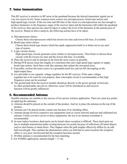
7. Noise Immunization<br />
This RF receiver is sensitive to RF noise in the passband because the desired transmitter signals are at<br />
very low power levels. Some common noise sources are microprocessors, brush-type motors and<br />
high-speed logic circuits. If the rise time and fall time of the clock in a microprocessor are fast enough to<br />
produce harmonics in the frequency range of the receiver input and the harmonics fall within the passband<br />
of the receiver, then special care must be taken to reduce the level of the harmonic at the antenna port of<br />
the receiver. Based on above analysis, the following actions have to be taken:<br />
A. Microprocessor choice:<br />
Choose those microprocessors which has lowest rise time and lowest fall time, if available.<br />
B. Brush-type motor choice:<br />
Choose those brush-type motors which has spark suppression built in or better not to use such<br />
type of motors.<br />
C. Logic circuits choice:<br />
High speed logic circuits generates noise similar to microprocessors. Thus better to choose those<br />
circuits with the lowest rise time and the lowest fall time, if available.<br />
D. Place the receiver and its antenna as far from the noise source as possible.<br />
E. During PCB layout, keep line lengths at a minimum that carry high speed logic signals or supply<br />
brush type motors. Such lines work like antennas that radiate the unwanted noise.<br />
F. If possible, enclose the noise source in a grounded metal box and use RF-decoupling on the<br />
input/output lines.<br />
G. It is advisable to use separate voltage regulator for the RF receiver. If the same voltage<br />
regulator has to be used for cost purpose, then a decoupler circuit is recommended so that high<br />
frequency noise can be screened.<br />
H. The ground path from the receiver module should go directly to the power ground, in between,<br />
no other ground paths can join in, otherwise, noise will be introduced in and receiver<br />
function will be greatly influenced.<br />
8. Recommended Antenna<br />
Suitable antennas are suitable to the success of low-power wireless application. There are some key points<br />
on applying the antennas:<br />
A, Antenna should be placed on the outside of the product. And try to place the antenna on the top of the<br />
product.<br />
B. Antenna can’t be placed inside a metal case because of its shielding effect.<br />
C. Antenna design involves expensive test equipments such as vector network analyzer and calibrated test<br />
antenna. Unless you have access to these equipments, the use to an antenna consultant is<br />
recommended.<br />
D. In most indoor locations, dead spots can be found where reception is difficult. These dead spots are<br />
due to multiple transmission paths existing between two points because of reflections off metal objects<br />
such as steel beams or metal doors. They happen when the path lengths effectively differs by an odd<br />
half-wavelength. This explains the phenomenon when you find that at some locations the reception<br />
effect is very poor, but beyond that the reception becomes normal.<br />
E. 50-Ohm antenna is recommended for the best matching.<br />
F. For 434MHz application, antenna length = 17 cm.<br />
9


