RX-3302/RX-3302R Manual - Kitsrus
RX-3302/RX-3302R Manual - Kitsrus
RX-3302/RX-3302R Manual - Kitsrus

Create successful ePaper yourself
Turn your PDF publications into a flip-book with our unique Google optimized e-Paper software.
November 22, 2002.<br />
Kit A17<br />
This is a condensed version of the Automicro General <strong>Manual</strong> where we have retained general information<br />
and information specifically relating to the Tx and Rx modules we are using and selling. We have deleted<br />
much of the other information on their other modules. Kit A17 consists of the following 2-button transmitter<br />
and receiver units.<br />
TX 3316RSA(A1) 434 MHz<br />
<strong>RX</strong> <strong>3302</strong>D2-15(2A1) 434 MHz.<br />
We are using these in Kit 157. Get the extensive documentation from<br />
http://www.kitsrus.com/pdf/k157.pdf<br />
which gives more information that that given here. Also read<br />
http://www.kitsrus.com/pdf/an662.pdf<br />
http://www.kitsrus.com/pdf/an665.pdf<br />
on details of KEELOQ technology. Note the Tx unit comes preassembled with the battery included.<br />
<strong>RX</strong>-<strong>3302</strong>D RF Receiver W/Decoder Operation <strong>Manual</strong><br />
1. Introduction<br />
This is a series of radio frequency receiver modules which can facilitate the OEM<br />
designers to design their applications in remote control in the quickest way. The circuit<br />
is designed with SMD components and the module size is small enough to be able to be<br />
fitted in many remote control applications. Decoder software, transmitter code learning<br />
and nonvolatile memory have all been integrated in. The decoder software available are:<br />
A. Rolling code using Microchip encoder HCS200 or HCS300 series.<br />
B. Fixed code using PT-2260 series encoder.<br />
There are the following versions:<br />
1) <strong>RX</strong>-<strong>3302</strong>D2: For 2-button transmitters.<br />
2) <strong>RX</strong>-<strong>3302</strong>D4: For 2 or 4 button transmitters.<br />
There are 3 more pins than the D2 version: Pin # 9: VPP, for factory programming<br />
1
only. No connection is needed.<br />
Pin #10: D2, for button #3<br />
Pin #11: D3 , for button #4<br />
D means decoder.<br />
For <strong>RX</strong>-<strong>3302</strong>D, the decoder function has been implemented in the on-board<br />
microprocessor. Besides, the code learning process has also been implemented. Thus<br />
it relieves the system’s design load on the remote control part totally.<br />
There are rolling code and fixed code variations which will be explained later.<br />
<strong>RX</strong>-<strong>3302</strong>D4 is an RF module with the following pin-outs and dimension:<br />
PIN 1 : GND PIN 2 : Digital Output<br />
PIN 3 : VCC (5V DC) PIN 4 : Linear Output (For Testing)<br />
PIN 5 : Valid Time, for 2A1 version, don’t care<br />
For 2Q1 version, this pin can be connected to a boozer so that it can indicate if<br />
code learning is successful. This application will be very convenient if the control receiver<br />
unit is installed in a hidden position.<br />
PIN 6 : D0<br />
PIN 7 : Learning Acknowledge PIN 8 : D1<br />
PIN 9 : VPP, for factory programming only, no connection.<br />
PIN 10 : D2 PIN 11 : D3<br />
PIN 12 : ANT (Antenna) PIN 13 : GND<br />
Dimension of <strong>RX</strong>-<strong>3302</strong>D4: 56.5 mm X 19.5 mm<br />
� Comparison Table: (Versus our <strong>RX</strong> Series)<br />
2
Model SR/SH<br />
mode<br />
POWER CPU+<br />
EEPROM<br />
SENSITIVITY POWER<br />
CONSUMPTION<br />
<strong>RX</strong>-<strong>3302</strong> SR +5V DC --- - 103dBm 1.60mA AM<br />
<strong>RX</strong>-3301 SR +5V DC --- - 103dBm 1.93mA AM<br />
<strong>RX</strong>-<strong>3302</strong>L SR +5V DC --- - 98dBm 0.33 mA AM<br />
<strong>RX</strong>-3304 SR +5V DC --- - 100dBm 2.7mA AM<br />
<strong>RX</strong>-<strong>3302</strong>R/F SR +5V DC YES - 105dBm 3.1mA AM<br />
<strong>RX</strong>-<strong>3302</strong>D SR +5V DC YES - 105dBm 2.7mA AM<br />
<strong>RX</strong>-4303D SH +5V DC --- - 110dBm 5.1mA AM<br />
<strong>RX</strong>F-4303D SH +5V DC YES - 100dBm 6.2mA FM<br />
Note:<br />
SR: Super-Regenerative SH: Super-Heterodyne<br />
AM: Amplitude Modulation FM: Frequency Modulation<br />
2. Functionality Difference:<br />
There are 2 major application types involved:<br />
2.1 For rolling code application:<br />
� <strong>RX</strong>-<strong>3302</strong>D<br />
Modulation<br />
<strong>RX</strong>-<strong>3302</strong>D includes the decoder CPU (PIC16C505) and the EEPROM (93C46 or 93C56 or 93C66<br />
or 93LC76 or 93LC86) on board. The code learning function has been built in.<br />
The main microprocessor can be programmed transparently without caring about the code learning<br />
programming and the rolling code programming.<br />
For <strong>RX</strong>-<strong>3302</strong>D, there are following receiver models (Decoder Version 2A1):<br />
For matching our 2-button rolling code transmitters (A1 type) :<br />
� <strong>RX</strong>-<strong>3302</strong>D2-15 (for 15 users, W / 93C46)<br />
� <strong>RX</strong>-<strong>3302</strong>D2-63 (for 63 users, W / 93C66)<br />
� <strong>RX</strong>-<strong>3302</strong>D2-127 (for 127 users, W / 93LC76).<br />
� <strong>RX</strong>-<strong>3302</strong>D2-255 (for 255 users, W / 93LC86).<br />
For matching our 2 or 4-button rolling code transmitters (A1 type):<br />
� <strong>RX</strong>-<strong>3302</strong>D4-15 (for 15 users, W / 93C46).<br />
� <strong>RX</strong>-<strong>3302</strong>D4-31 (for 31 users, W / 93C56).<br />
� <strong>RX</strong>-<strong>3302</strong>D4-63 (for 63 users, W / 93C66).<br />
� <strong>RX</strong>-<strong>3302</strong>D4-127 (for 127 users, W / 93LC76).<br />
� <strong>RX</strong>-<strong>3302</strong>D4-255 (for 255 users, W / 93LC86).<br />
All our AM rolling code transmitters with 2~4 buttons from Automicro with A1 label can work with<br />
<strong>RX</strong>-<strong>3302</strong>D.<br />
3
� Frequency Bandwidth<br />
<strong>RX</strong>-<strong>3302</strong>D: 434MHz, LC, 4MHz Bandwidth.<br />
� Programming the Main Microprocessor and <strong>RX</strong>-<strong>3302</strong>D2:<br />
1. For rolling code:<br />
Using TX-3315 (S) / TX-3312R / TX(F)-3313R /TX-3316R(S) (W / HCS-200 or HCS-301 from<br />
Microchip, programmed with our version A1) with two buttons but 3 commands<br />
available.<br />
VT D0 D1<br />
When button #1 is being pressed Don’t Care HIGH LOW<br />
When button #2 is being pressed Don’t Care LOW HIGH<br />
When button #1 & #2 are being pressed Don’t Care HIGH HIGH<br />
D0 and D1 will become HIGH as long as the proper button is being pressed, i.e., D0 will be HIGH if<br />
button #1 is being pressed and D1 will be HIGH if button #2 is being pressed. VT will be HIGH as<br />
long as any of D0 or D1 is HIGH, but VT can be ignored by the programming.<br />
� Programming the Main Microprocessor using <strong>RX</strong>-<strong>3302</strong>D4 and TX-4311R / TX-4314R /<br />
TX-4313R(S) /TX-4312R(S) (W / HCS-301 from Microchip, programmed with version<br />
A1) of 4-button transmitter, there are extra six double-button commands available<br />
in addition to four single-button commands.<br />
VT D0 D1 D2 D3<br />
When button #1 is being pressed Don’t Care HIGH LOW LOW LOW<br />
When button #2 is being pressed Don’t Care LOW HIGH LOW LOW<br />
When button #3 is being pressed Don’t Care LOW LOW HIGH LOW<br />
When button #4 is being pressed Don’t Care LOW LOW LOW HIGH<br />
When button #1 and #2 are being pressed Don’t Care HIGH HIGH LOW LOW<br />
When button #1 and #3 are being pressed Don’t Care HIGH LOW HIGH LOW<br />
When button #1 and #4 are being pressed Don’t Care HIGH LOW LOW HIGH<br />
When button #2 and #3 are being pressed Don’t Care LOW HIGH HIGH LOW<br />
When button #2 and #4 are being pressed Don’t Care LOW HIGH LOW HIGH<br />
When button #3 and #4 are being pressed Don’t Care LOW LOW HIGH HIGH<br />
Each D0, D1,D2 or D3 will become HIGH as long as the proper button is being pressed. VT will be<br />
HIGH as long as any of D0 or D1 or D2 or D3 is HIGH, but VT can be ignored by the<br />
4
programming.<br />
+ Notes:<br />
For our rolling code transmitters, we have the following labels on the encoders (HCS200 or HCS300<br />
or HCS301):<br />
� A1: For <strong>RX</strong>-<strong>3302</strong>R/D, <strong>RX</strong>(F)-4303D, CS-04R2, CS-04R4, CS-281, CS-28, CS-20CR<br />
� B1: For CS-04R, CS-04G, CS-06<br />
� C1, W1…: For OEM customers with their specific manufacturer codes.<br />
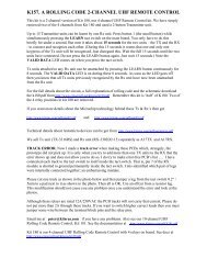
� Learning Mode (For <strong>RX</strong>-<strong>3302</strong>D):<br />
The LA (Learning Acknowledge) pin will be at HIGH normally and acts as an input. If this pin is put<br />
to LOW temporarily by a tact switch, then it remains at LOW and becomes an output for 15 only<br />
seconds during which a transmitter code can be learned if button #1 of any of our applicable<br />
transmitters is pressed. After 15 seconds of period expires, then this pin restores to HIGH again.<br />
+ Note that only button #1 can be used for code learning.<br />
5
No<br />
Learning acknowledge pin (LAP) pulled low<br />
Enter learning mode & LAP is changed as<br />
output pin & output becomes low<br />
15 sec time-out?<br />
Valid transmitter #1 is pressed<br />
No<br />
Compare with codes learned<br />
VT goes high temporarily & 1 learning completed<br />
Learn code 64 th now?<br />
First in first out<br />
Yes<br />
Yes<br />
15 sec time out<br />
If 15 seconds of period is not long enough for learning all the transmitters, then the 2nd or the 3rd cycle<br />
of learning can be done until all the transmitters (up to 15 or 31 or 63 or 127 or 225 depending on which<br />
model of <strong>RX</strong>-<strong>3302</strong>D) is learned.<br />
If you want to erase all the transmitters learned, then please put the LA (Learning Acknowledge) pin to<br />
LOW for more than 10 seconds, then all the prior codes learned will be erased completely.<br />
� Note that if the same transmitter is learned twice, it will be treated as only one transmitter without<br />
wasting any of the memory slot.<br />
Regarding synchronization between <strong>RX</strong>-<strong>3302</strong>D and each rolling-code transmitter, if more than 16 times<br />
that the receiver has not received the signals transmitted from each rolling-code transmitter, then the<br />
receiver needs one extra signal from the transmitter for synchronization.<br />
Exit<br />
� Note that there are the following software<br />
6
versions for the rolling code models:<br />
1. 2A1: Standard version.<br />
2. 2B3: Besides the standard features, it has an additional feature as follows:<br />
Pressing two buttons of any transmitter learned earlier for more than 4 seconds, then the<br />
system will enter transmitter code learning mode. This is good if the learning button is not<br />
easily accessible after installation.<br />
Both versions can use pin #5 (VT) instead of pin #7 (LA) for indicating the status of the code<br />
learning process. Pin #5 can be connected to a boozer via a transistor so that it can facilitate the<br />
code<br />
learning process as follows:<br />
1) Press the learn button, then the boozer beeps once indicating that 15 seconds of code<br />
learning process starts.<br />
2) Press any unlearned transmitter will beep the boozer as long as the button is being pressed.<br />
3) Up to 15 transmitters can be learned in one or more learning cycles for the 15-user version.<br />
4) If more than 15 transmitters are learned, then FIFO happens which means that the 16 th<br />
learned transmitter will replace the first transmitter learned.<br />
5) When 15 seconds of learning cycle ends, the boozer will beep twice.<br />
6) You can delete all the codes learned earlier by pressing the learning button for more than 8.3<br />
seconds and the boozer will beep all along in this period. When the boozer stops, all the<br />
transmitters codes learned are also deleted.<br />
3. <strong>RX</strong>-<strong>3302</strong>D Features<br />
� Using Microchip hopping technology<br />
� Work with HCS series of encoders<br />
� Support two-button, 3 functions or 4-button, 11 functions transmitters.<br />
� Unique key generation algorithm for every customer.<br />
� No user programming required for either the rolling code or fixed code.<br />
� Up to 15 / 31/ 63 /127 / 255 transmitters can be learned.<br />
� On-chip 4 Mhz RC oscillator.<br />
� 16C505 SMD<br />
4. APPLICATIONS<br />
� Automotive remote entry systems<br />
� Automotive alarm systems<br />
� Automotive immobilizer<br />
� Gate and garage door openers<br />
� Electronic door locks<br />
� Identity tokens<br />
� Burglar alarm systems<br />
5. Descriptions<br />
In <strong>RX</strong>-<strong>3302</strong>D(2A1), the built-in 16C505 is a code hopping decoder designed for secure Remote Keyless<br />
Entry (RKE) systems. The <strong>RX</strong>-<strong>3302</strong>D utilizes the patented Microchip code hopping system and high<br />
security learning mechanisms to make this a canned solution when used with our rolling-code<br />
transmitters to implement a unidirectional remote control keyless entry system.<br />
7
The key generation algorithm is programmed into the 16C505 decoder in protected mode and can not be<br />
read out of the device. Transmitter keys and synchronization counter are stored in its external EEPROM<br />
(93C46 or 93C56 or 93C66 or 93LC76 or 93LC86).<br />
The <strong>RX</strong>-<strong>3302</strong>D operates over a range of 5.0 ~ 5.5 V. The decoder employs automatic baud rate. The<br />
decoder contains sophisticated error checking algorithm to ensure only valid codes are accepted and<br />
correct information are written into its external EEPROM.<br />
6. Simple Application Board Circuit<br />
Application notes:<br />
1. The power circuit for VCC is recommended to use a regulator such as 78L05 and a capacitor at<br />
least 47uF so that ripple can be reduced.<br />
2. If the microprocessor is working with high speed crystal, then <strong>RX</strong>-4303D is<br />
recommended because the radiation is too strong.<br />
3. Note that there are different grounds in the above circuits.<br />
The ground of the RF receiver module is analog and the ground of the CPU is analog.<br />
The analog ground is very sensitive to noise, thus it should not be mixed to digital ground in the<br />
PCB layout circuit.<br />
4. For PCB layout, the ground of this receiver module to the power ground should be as short as<br />
possible. In between, no other grounds are allowed to join in. The receiver module is analog and it<br />
is very sensitive and prone to noise interference. The ground of the microprocessor or operation<br />
amplifier should go a separate path to power ground.<br />
5. There are Design Kit for this module from us which can facilitate you to design your product<br />
by using this receiver module in similar way.<br />
8
7. Noise Immunization<br />
This RF receiver is sensitive to RF noise in the passband because the desired transmitter signals are at<br />
very low power levels. Some common noise sources are microprocessors, brush-type motors and<br />
high-speed logic circuits. If the rise time and fall time of the clock in a microprocessor are fast enough to<br />
produce harmonics in the frequency range of the receiver input and the harmonics fall within the passband<br />
of the receiver, then special care must be taken to reduce the level of the harmonic at the antenna port of<br />
the receiver. Based on above analysis, the following actions have to be taken:<br />
A. Microprocessor choice:<br />
Choose those microprocessors which has lowest rise time and lowest fall time, if available.<br />
B. Brush-type motor choice:<br />
Choose those brush-type motors which has spark suppression built in or better not to use such<br />
type of motors.<br />
C. Logic circuits choice:<br />
High speed logic circuits generates noise similar to microprocessors. Thus better to choose those<br />
circuits with the lowest rise time and the lowest fall time, if available.<br />
D. Place the receiver and its antenna as far from the noise source as possible.<br />
E. During PCB layout, keep line lengths at a minimum that carry high speed logic signals or supply<br />
brush type motors. Such lines work like antennas that radiate the unwanted noise.<br />
F. If possible, enclose the noise source in a grounded metal box and use RF-decoupling on the<br />
input/output lines.<br />
G. It is advisable to use separate voltage regulator for the RF receiver. If the same voltage<br />
regulator has to be used for cost purpose, then a decoupler circuit is recommended so that high<br />
frequency noise can be screened.<br />
H. The ground path from the receiver module should go directly to the power ground, in between,<br />
no other ground paths can join in, otherwise, noise will be introduced in and receiver<br />
function will be greatly influenced.<br />
8. Recommended Antenna<br />
Suitable antennas are suitable to the success of low-power wireless application. There are some key points<br />
on applying the antennas:<br />
A, Antenna should be placed on the outside of the product. And try to place the antenna on the top of the<br />
product.<br />
B. Antenna can’t be placed inside a metal case because of its shielding effect.<br />
C. Antenna design involves expensive test equipments such as vector network analyzer and calibrated test<br />
antenna. Unless you have access to these equipments, the use to an antenna consultant is<br />
recommended.<br />
D. In most indoor locations, dead spots can be found where reception is difficult. These dead spots are<br />
due to multiple transmission paths existing between two points because of reflections off metal objects<br />
such as steel beams or metal doors. They happen when the path lengths effectively differs by an odd<br />
half-wavelength. This explains the phenomenon when you find that at some locations the reception<br />
effect is very poor, but beyond that the reception becomes normal.<br />
E. 50-Ohm antenna is recommended for the best matching.<br />
F. For 434MHz application, antenna length = 17 cm.<br />
9