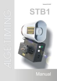
Manual - ALGE-TIMING
Manual - ALGE-TIMING
Manual - ALGE-TIMING

Create successful ePaper yourself
Turn your PDF publications into a flip-book with our unique Google optimized e-Paper software.
Version-E080421<br />
<strong>Manual</strong>
Seite 2<br />
TED-TX / RX<br />
1 antenna<br />
2 green holder with velcro fastener<br />
3 light-emitting diode<br />
4 banana plug yellow, data input<br />
5 banana plug green, signal input<br />
6 banana plug black, shared ground (compound)<br />
7 DIN-plug: data and signal input as well as external feed<br />
8 3/8 thread measured in inches, for tripod fastening<br />
9 code-switcher (16 positions)<br />
10 device-button<br />
11 device-switcher<br />
12 code-switcher (10 positions)<br />
13 fastening screw for battery-cover<br />
14 battery-cover<br />
15 type shield with device number<br />
1 antenna<br />
2 red holder with velcro fastener<br />
3 light-emitting diode<br />
4 banana plug yellow, data output<br />
5 banana plug green, signal output<br />
6 banana plug black, shared ground (compound)<br />
7 DIN-plug: data and signal output as well as external feed<br />
8 3/8 thread measured in inches, for tripod fastening<br />
9 code-switcher (16 positions)<br />
10 device-button<br />
11 device-switcher<br />
12 code-switcher (10 positions)<br />
13 fastening screw for battery cover<br />
14 battery cover<br />
15 type shield with device number
TED-TX / RX<br />
Table of content<br />
1 General ....................................................................................................................................... 4<br />
2 Power supply ............................................................................................................................. 5<br />
2.1 Battery exchange......................................................................................................................... 5<br />
2.2 Operation with Alkaline batteries................................................................................................. 6<br />
2.2.1 Battery warning........................................................................................................................ 6<br />
2.2.2 Operation time ......................................................................................................................... 6<br />
2.3 Operation with NiCd-accus.......................................................................................................... 7<br />
2.3.1 Accu warning ........................................................................................................................... 7<br />
2.3.2 Operation time ......................................................................................................................... 7<br />
2.4 External supply ............................................................................................................................ 8<br />
2.4.1 Direct supply............................................................................................................................ 8<br />
2.4.2 Supply by the timing device..................................................................................................... 8<br />
3 Implementation .......................................................................................................................... 9<br />
3.1 Installation.................................................................................................................................... 9<br />
3.2 Switch-on................................................................................................................................... 10<br />
3.3 Choice of operation mode ......................................................................................................... 11<br />
3.4 Addressing................................................................................................................................. 12<br />
3.5 Field strength test for site selection........................................................................................... 13<br />
3.6 Annoyance test – tapping of the receiver for disturbing signals................................................ 14<br />
4 Impulse transmission.............................................................................................................. 15<br />
4.1 Impulse transmission of a startgate........................................................................................... 16<br />
4.2 Impulse transmission of a photocell .......................................................................................... 16<br />
4.3 Impulse transmission RLS with adapter 129-06........................................................................ 17<br />
4.4 Impulse transmission with more than 2 timing channels........................................................... 17<br />
4.5 Impulse transmission of more timing channels with Timy and cable 207-10 ............................ 19<br />
5 Data transmission ................................................................................................................... 20<br />
5.1 Data transmission 1 second ...................................................................................................... 21<br />
5.1.1 Data transmission from Timer S4 to Timer S4 ...................................................................... 21<br />
5.1.2 Data transmission from <strong>ALGE</strong> timing device to printer P4A.................................................. 22<br />
5.2 Data transmission 0,1 seconds ................................................................................................. 23<br />
5.2.1 Data transmission to <strong>ALGE</strong> displayboard.............................................................................. 23<br />
5.2.2 Data transmission from Comet to <strong>ALGE</strong> soccer displayboard .............................................. 23<br />
5.2.3 Data transmission from a <strong>ALGE</strong> timing device to Comet Parallel display............................. 24<br />
5.2.4 Data transmission from <strong>ALGE</strong> timing device to PC............................................................... 24<br />
5.3 Data transmission directly ......................................................................................................... 24<br />
6 Technical data.......................................................................................................................... 25<br />
Subject to technical alterations in terms of improvement!<br />
Download the latest manual for free on our homepage http://www.alge-timing.com/.<br />
TED manual copyright by: <strong>ALGE</strong>-<strong>TIMING</strong><br />
Rotkreuzstraße 39<br />
A-6890 Lustenau<br />
Seite 3
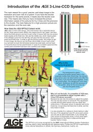
1 General<br />
Seite 4<br />
TED-TX / RX<br />
Purpose: Wireless transfer of timing impulses or data<br />
Transfer frequency : in 70cm band<br />
TED-TX10: Teledata transmitter with an output performance of 10mW<br />
appr. 1,5 km range, l/4 antenna<br />
TED-RX10: Teledata receiver to TED-TX10 with l/4 antenna<br />
TED-TX400: Teledata transmitter with an output performance of 400mW<br />
appr. 5 km range, BNC antenna<br />
TED-RX400: Teledata receiver to TED-TX400 with BNC antenna<br />
Minimal equipment components: 1x TED-TX and 1x TED-RX<br />
Expanded Accessories: added TED-TX for impulse and data transfer, added TED-RX<br />
for data transfer<br />
RX-C10 for impulse transfer if you use more than two timing<br />
channels<br />
Cognition feature for TED-TX: type shield (15) and green holder (2)<br />
Cognition feature for TED-RX: type shield (15) and red holder (2)<br />
Indication on type shield: device type<br />
device number<br />
Impulse transfer: The impulse transfer works directly from a <strong>ALGE</strong>-emitter to the<br />
<strong>ALGE</strong> timing device.<br />
Data transfer <strong>ALGE</strong> "1 Sec.": Every data set will be transfered 10 times out of<br />
safety reasons. Onedata set per second will be<br />
transfered.<br />
Data transfer <strong>ALGE</strong> "0,1 Sec": Every data set will be transfered once. One data<br />
set per 0,1 seconds will be transfered.<br />
Data transfer 2400 Baud: Every data set will be transfered once with 2400<br />
Baud. At the beginning as well as at the end of<br />
each data set you have to indicate an identifier in<br />
order to start and to stop the data transfer.<br />
Data transfer 4800 Baud: Every data set will be transfered once with 4800<br />
Baud. At the beginning as well as at the end of<br />
each data set you have to indicate an identifier in<br />
order to start and to stop the data transfer.<br />
Data transfer directly: All data will be transfered, the transmitter (TED-<br />
TX) is always on.
TED-TX / RX<br />
System test: Field strength test<br />
Annoyance test<br />
Power supply: with 6 batteries or with 6 NiCd-accus or with<br />
external supply<br />
Radio permission:<br />
The permission regulations in Europe variies from country to country.<br />
For some countries you have to apply for a permission for our TED-TX400.<br />
If you need any information concerning this matter , please get in contact with your <strong>ALGE</strong><br />
representative.<br />
2 Power supply<br />
There are two types of power supply:<br />
Internal power supply with six batteries (Mignon) or accus (Typ AA)<br />
External power supply with <strong>ALGE</strong> power supply unit, via timing device or a 12V<br />
battery.<br />
2.1 Battery exchange<br />
You can reach the battery cover at the lower side of<br />
the TED´s.<br />
The knurled screw must be unscrewed anticlockwise.<br />
Remove the cover.<br />
Remove the batteries (put up the device in order that the<br />
batteries will slip out.)<br />
Set in the new (or loaded) battery.<br />
(Notice the polarity, see battery cover)<br />
Put on the cover and screw the knurled screw.<br />
The screw must be screwed to the stop position.<br />
Seite 5
Seite 6<br />
TED-TX / RX<br />
2.2 Operation with Alkaline batteries<br />
Every TED requires 6 Alkaline batteries (Type AA). The battery status will be shown during<br />
the normal operation with help of the diodes.<br />
Color of diode (3) Battery capacity<br />
green 35-100 %<br />
border between green and orange ca. 35 %<br />
orange 20 to 35 %<br />
border between orange and red ca. 20 %<br />
red less than 20 %<br />
out empty<br />
The TED switches-off automatically, if the battery tension is below 5 Volt!<br />
ATTENTION: The light-emitting diode has an other function during the field strength test!<br />
(see point 3.5)<br />
2.2.1 Battery warning<br />
If the battery has less than 20% capacity (LED red) then the TED-TX will transfer this<br />
information the the TED-RX together with the next data set or information. He will switch-on<br />
the internal loudspeaker, after that you can hear alternately a high-pitched and a low tone.<br />
The TED-RX will always activiate the internal loudspeaker as soon as the battery capacity is<br />
below 20%.<br />
2.2.2 Operation time<br />
The above indicated measurings refer to Alkaline batteries (Type Energizer) at room<br />
temperatures (25°C).<br />
Please pay attention to the fact, that the battery capacity will be extremely reduced at low<br />
temperatures. (at –20°C approx. just 20% capacity).<br />
TED-TX10 without photocell 1 impulse per minute approx. 300 hours<br />
TED-TX10 with photocell 1 impulse per minute approx. 66 hours<br />
TED-TX10 --- 1 data set per minute approx. 270 hours<br />
TED-TX10 --- always sends data approx. 54 hours<br />
TED-TX400 without photocell 1 impulse per minute approx. 270 hours<br />
TED-TX400 with potocell 1 impulse per minute approx. 60 hours<br />
TED-TX400 --- 1 data set per minute approx. 54 hours<br />
TED-TX400 --- always sends data approx. 6 hours<br />
TED-RX --- the same in all<br />
operation modes<br />
approx. 54 hours
TED-TX / RX<br />
2.3 Operation with NiCd-accus<br />
Every TED requires 6 NiCd-accus (Typ AA).The accus cannot be loaded in the device. In<br />
order to load you will need a separately loading station. The accu sitution (accu capacity) will<br />
be shown during the normal operation with help of the light-emitting diodes (3).<br />
Color of diode (3) Battery capacity<br />
green 15 to 100 %<br />
border between green and orange approx. 15 %<br />
orange 5 to 15 %<br />
border between orange and red approx. 5 %<br />
red less than 5 %<br />
out empty<br />
The TED switches automatically off, if the battery pressure goes below 5 Volt!<br />
Attention: The light-emitting diode has an other function during the field strength test! (see<br />
point 3.5)<br />
2.3.1 Accu warning<br />
The same as Alkaline batteries.<br />
2.3.2 Operation time<br />
The above indicated measurings refer to accus of the type Panasonic 700mAh at room<br />
temperatures (25°C).<br />
Please pay attention to the fact, that the battery capacity will be reduced at low temperatures.<br />
(at –20°C approx. just 80% capacity).<br />
TED-TX10 without photocell 1 impulse per minute approx. 100 hours<br />
TED-TX10 with photocell 1 impulse per minute approx. 22 hours<br />
TED-TX10 --- 1 data set per minute approx. 90 hours<br />
TED-TX10 --- always sends data approx. 18 hours<br />
TED-TX400 without photocell 1 impulse per minute approx. 90 hours<br />
TED-TX400 with photocell 1 impulse per minute approx. 20 hours<br />
TED-TX400 --- 1 data set per minute approx. 18 hours<br />
TED-TX400 --- always sends data approx. 2 hours<br />
TED-RX --- the same in all operation<br />
modes<br />
approx. 18 hours<br />
Seite 7
2.4 External supply<br />
Seite 8<br />
TED-TX / RX<br />
The TED can be supplied by a power supply unit.<br />
Supply pressure:<br />
TED-TX10 +6,5 to 28 VDC<br />
TED-TX400 +9 to 15 VDC<br />
TED-RX +6,5 to 28 VDC<br />
2.4.1 Direct supply<br />
The TED can be supplied directly by the following <strong>ALGE</strong><br />
power supply units:<br />
NLG4<br />
NLG8<br />
LG-Comet (not for TED-TX400)<br />
NBG<br />
NG13<br />
PS12<br />
2.4.2 Supply by the timing device<br />
In the operation type impulse transfer, the TED-RX can be supplied by the power supply unit<br />
ot the timing device. Therefore you need cable 004-05 between the TED-RX and the timing<br />
device.<br />
ATTENTION: The supply just functions, if the timing device is connected to an external<br />
supply.<br />
LG-Comet cannot supply Comet and the TED at the same time.
3 Implementation<br />
TED-TX / RX<br />
The reach of the radio contact is strongly depending on the location of the transmitter and<br />
receiver. In many cases you can improve the received field strength (high field strength =<br />
high safety) by a minimal relocation if the TED-TX or RX.<br />
3.1 Installation<br />
There are different possibilities to mount the TED:<br />
Bad:<br />
The TED should never<br />
stand on the ground.<br />
Too much reach will be<br />
lost.<br />
Bad:<br />
The antenna must<br />
always be uprightly.<br />
Bad:<br />
There mustn’t be any<br />
parts near the antenna!<br />
Good:<br />
Mounting with Velcro<br />
fastener. In critical<br />
situations, always make<br />
an over-head-mounting.<br />
Good:<br />
Mounting on a tripod<br />
(3/8 inch)<br />
Seite 9
3.2 Switch-on<br />
Seite 10<br />
TED-TX / RX<br />
Used for small and middle distances.<br />
Normal operation - Switch-on with device-switcher (11)<br />
- TED works in operation mode „Impulse transfer“<br />
- Light-emitting diode blinks<br />
Test-Mode - Push device-switcher (10)<br />
- Device-switcher (11) to „ON“, light-emitting diode should blink<br />
- Let loose of the device-switcher.<br />
- Test-Mode will automatically switch-off after one minute,<br />
manually with device-switcher (10)<br />
Data transfer <strong>ALGE</strong> 1 Sec.<br />
- Switch-on theTED, light-emitting diode must blink<br />
- If the first data set is transfered in the right format, then the data<br />
transfer will be activated for 1 second.<br />
Data transfer <strong>ALGE</strong> 0,1 Sec.<br />
- Set code-switcher (12) of TED-TX and RX to position 1<br />
- Switch-on the TED, light-emitting diode must blink<br />
Data transfer 2400 Baud<br />
- Set code-switcher of TED-TX and RX to position 3.<br />
- Switch-on the TED, light-emitting diode must blink<br />
- Every data set will be transfered once with 2400 Baud.<br />
- At the beginning as well as at the end of each data set you<br />
have to indicate an identifier in order to start and to stop the<br />
data transfer.
TED-TX / RX<br />
Data transfer 4800 Baud<br />
- Set code-switcher of TED-TX and RX to position 4.<br />
- Switch-on the TED, light-emitting diode must blink<br />
- Every data set will be transfered once with 4800 Baud.<br />
- At the beginning as well as at the end of each data set you<br />
have to indicate an identifier in order to start and to stop the<br />
data transfer.<br />
Data transfer directly<br />
- Set code-switcher of TED-TX and RX to position 6.<br />
- Light-emitting diode of TED-RX must shine.<br />
- Light-emitting diode of TED-TX blinks. At first you<br />
have to send a data set that the TED-TX switch<br />
in the direct mode (illuminating diode goes<br />
from blinking to shine).<br />
- Every data set will be transfered.<br />
3.3 Choice of operation mode<br />
Switcher Signal mode Data mode<br />
Code-switcher<br />
(12)<br />
Position 0 to 9<br />
for choice of timingchannel<br />
Position 0: data transfer <strong>ALGE</strong> 1 second<br />
Position 1: data transfer <strong>ALGE</strong> 0,1 second<br />
Position 2: without function<br />
Position 3: data transfer 2400 Baud<br />
Position 4: data transfer 4800 Baud<br />
Position 6: data transfer directly<br />
Position 7 to 9: without function<br />
Code-switcher (9) for addressing for addressing<br />
Device-pushbutton<br />
(10)<br />
field strength tst On/Off repeat last data set<br />
The field strength test can also be started by triple short-circuiting of the green and black<br />
banana plug.<br />
Seite 11
3.4 Addressing<br />
Seite 12<br />
TED-TX / RX<br />
The code-switcher (9) for addressing has got 16 positions<br />
and is accessible from the bottom. All TED-TX and RX must be<br />
installed to the same address if they work in one system.<br />
Chose the requested address with the<br />
provided screw driver. The arrow of the<br />
switcher shows the position. Our factory<br />
settins is at position 0.<br />
If several TED’s are used in the same<br />
area, you have to work with different<br />
addresses. So you are safe of false<br />
impulses or data, though not against<br />
blocking of another device.<br />
If you will avoid any blocking of another TED, so you have to change to another radiofrequency.<br />
Example impulse-transfer of start signal<br />
TED –TX and RX must be adjusted to the same address.<br />
Code-switcher (9) Address<br />
Position = 0 Address = 0<br />
Position = 1 Address = 1<br />
Position = 2 Address = 2<br />
Position = 3 Address = 3<br />
Position = 4 Address = 4<br />
Position = 5 Address = 5<br />
Position = 6 Address = 6<br />
Position = 7 Address = 7<br />
Position = 8 Address = 8<br />
Position = 9 Address = 9<br />
Position = A Address = A<br />
Position = B Address = B<br />
Position = C Address = C<br />
Position = D Address = D<br />
Position = E Address = E<br />
Position = F Address = F
TED-TX / RX<br />
3.5 Field strength test for site selection<br />
The field strength test can just be carried out in the operation mode „impulse transfer“.<br />
If you would like to work smooth with your TED, you have to choose an appropriate location.<br />
Activate field strength:<br />
- Switch-on TED-TX<br />
- Push device-button (10)<br />
- Mount the TED aloft.(side 9)<br />
- Switch-on TED-RX<br />
- The loudspeaker of the TED-RX makes a tone and the lightemitting<br />
diode blinks.<br />
- The higher the tone, the better the field strength.<br />
- Diode blinks green > Signal is good<br />
Diode blinks orange > Signal is low<br />
Diode blinks red > Signal missing or too low<br />
- If the loudspeaker plays back voices, it means that this radio<br />
frequency is used for voice radio. This can cause data or<br />
impulse losses.<br />
- The field strength test will automatically be finished after 1<br />
minute by the TED-TX.<br />
For the retrieval of the ideal location you have to move the TED-RX. The best location is<br />
chosen if the tone is as high as possible and if the diode is blinking green.<br />
The field strength can only be evaluated with TED-RX!<br />
TED-TX and RX must have a distance of 5 to 10 meters between them to assure a troublefree<br />
work.<br />
Seite 13
Seite 14<br />
TED-TX / RX<br />
3.6 Annoyance test – tapping of the receiver for<br />
disturbing signals<br />
If you push the device-button of the TED-RX for about half a second, the loudspeaker will be<br />
activated and you can intercept the channel for possible disturbing signals.<br />
At the same time the light-emitting diode shows the field strength of the received signals,<br />
also those of a possible disquieter<br />
ATTENTION:<br />
The electric power consumption of the TED-RX doubles during this test.<br />
Push the device-button to switch-off the loudspeaker.
4 Impulse transmission<br />
TED-TX / RX<br />
The impulse transmission functions directly from an <strong>ALGE</strong> emitter to a <strong>ALGE</strong> timing device<br />
via radio.<br />
Every impulse, transfered by the TED, has a constantly delay of 0,100 seconds.<br />
Maximum fault ; 0,001 seconds.<br />
If only the start impulse is transfered by TED, you have to add a tenth second to the<br />
run time.<br />
If only the finish impulse is transfered by TED, you have to discount a tenth second of<br />
the run time.<br />
If the start impulse as well as the finish impulse is transfered by TED, the run time is<br />
accurately.<br />
TED-TX is from the beginning of the first impulse blocked for 0,163 seconds respectively<br />
incidental impulses within this time will be delayed until this time is expired.<br />
TED-RX is from the beginning of the first impulse blocked for 0,1 seconds and ignores all<br />
impulses within this period.<br />
Bounce protection<br />
+5V<br />
Inside the TED-TX is a built-in bounce<br />
protection integrated. This bounce protection<br />
prevents double-impulses. (50 ms)<br />
0V<br />
A Bounce at the beginning of an impulse<br />
B Bounce at the end of an impulse<br />
C Impulse duration plus bounce duration<br />
D Bounce protection time 50 ms<br />
E Bounce protection abrupted,<br />
since 50 ms were not expired<br />
Control of the impulse transmission<br />
C<br />
A B<br />
If a timing impulse is transfered, the diode of TED-TX and RX will blink once again.<br />
Safety of the impulse transmission<br />
Please bare in mind that the radio connection may be disturbed by outside influences. That<br />
means that in case of annoyances, there can’t be any transmissions of impulses.<br />
!! With an impulse transmission via radio we can never assure the same security as by an<br />
impulse transmission by cable. !!<br />
The following <strong>ALGE</strong>-devices can be used as emitter:<br />
all startgates<br />
photocells RLS, RLS3<br />
SM8, STB1, Tapeswitch, hand taste 023-xx<br />
Touchpads TP<br />
ASC<br />
E<br />
E<br />
D<br />
Seite 15
Seite 16<br />
TED-TX / RX<br />
The following <strong>ALGE</strong> timing devices can be used as impulse receiver:<br />
TDC4000<br />
TDC8000<br />
TDC8001<br />
Timy<br />
Comet<br />
Timer S4<br />
Timer S3<br />
Videotimer VT2 / VT2D<br />
OPTIc (only start impulse)<br />
With the standard TED, two timing channels can be transmitted. Normally – if cable 004-xx is<br />
used – it will be start channel C0 and finish channel C1.<br />
4.1 Impulse transmission of a startgate<br />
4.2 Impulse transmission of a photocell
TED-TX / RX<br />
4.3 Impulse transmission RLS with adapter 129-06<br />
You can adjust with adapter 129-06 if you will receive a start or stop impulse.<br />
This has the advantage if you have e.g. a round course, you just need one photocell.<br />
4.4 Impulse transmission with more than 2 timing<br />
channels<br />
Here you need adapter RX-C10 so that you can transfer up to 10 timing channels in<br />
connection with TDC8000/8001 and Timer S4. Therefore you need several TED-TX. You can<br />
transfer 2 timing channels per TED-TX.<br />
You can adjust the timing channels at the TED-TX with the code-switcher (12).<br />
The code-switcher (12) don’t have any function in this operation.<br />
ATTENTION: Blocking time (see point 4, impulse transmission)<br />
With the small provided screw driver you can adjust the<br />
arrow of the code-switcher to the right position.<br />
TED-TX TED-TX timing channel TED-TX DIN-socket TED-TX DIN-Stecker<br />
Code-Schalter (12) banana socket timing channel timing channel<br />
green (5) and black (6) on pin 1 on pin 2<br />
switch position = 0 0 0 1<br />
switch position = 1 1 1 2<br />
switch position = 2 2 2 3<br />
switch position = 3 3 3 4<br />
switch position = 4 4 4 5<br />
switch position = 5 5 5 6<br />
switch position = 6 6 6 7<br />
switch position = 7 7 7 8<br />
switch position = 8 8 8 9<br />
switch position = 9 0 0 2<br />
Seite 17
Seite 18<br />
TED-TX / RX<br />
Timing with 10 timing channnels at a Ski test run:<br />
Adjustment of the code-switcher (12) to the TED-TX<br />
Channel Function Emitter<br />
Switcher<br />
position (12)<br />
Cable type<br />
Connection plug<br />
at TED-TX<br />
C0 Start Startgate 0 000-10 Banana plug 5+6<br />
C2 Intermediate time 1 Photocell 1 001-10 DIN-plug (7)<br />
C3 Intermediate time 2 Photocell 2 001-10 DIN-plug (7)<br />
C4 Intermediate time 3 Photocell 3 001-10 DIN-plug (7)<br />
C5 Intermediate time 4 Photocell 4 001-10 DIN-plug (7)<br />
C6 Intermediate time 5 Photocell 5 001-10 DIN-plug (7)<br />
C7 Intermediate time 6 Photocell 6 001-10 DIN-plug (7)<br />
C8 Intermediate time 7 Photocell 7 001-10 DIN-plug (7)<br />
C9 Intermediate time 8 Photocell 8 001-10 DIN-plug (7)<br />
C1 Finish Photocell 0 001-10 DIN-plug (7)
TED-TX / RX<br />
4.5 Impulse transmission of more timing channels with<br />
Timy and cable 207-10<br />
The cable 207-10 works only with the Timy. You can only use start cables (000-xx or<br />
002-xx) for this system. There will be no impulse and also the Timy prints an error message<br />
when you use a stop cable.<br />
These are the functions of the code switch (12). This have no use in the program Training<br />
REF, here it is only necessary that the TED channels are different.<br />
Codeswitch Chanal Function<br />
0 C0 Start<br />
1 C1 Finish<br />
2 C2 Intermediate<br />
3 C3 Intermediate<br />
4 C4 Intermediate<br />
5 C5 Intermediate<br />
6 C6 Intermediate<br />
7 C7 Intermediate<br />
8 C8 Intermediate<br />
9 C0 Start<br />
Seite 19
5 Data transmission<br />
Operational area:<br />
Seite 20<br />
TED-TX / RX<br />
Data transmission from an <strong>ALGE</strong> timing device to a <strong>ALGE</strong> displayboard<br />
Data transmission from Timer S4 to Timer S4 (program 0)<br />
Data transmission from <strong>ALGE</strong> timing device to printer P4A<br />
Data transmission from <strong>ALGE</strong> timing device to Comet parallel display<br />
Data transmission from Comet to football-displayboard<br />
Data transmission from <strong>ALGE</strong>-timing device to a PC<br />
Data transmission from PC to PC<br />
There exists different types of operating modes for data transmission:<br />
Data transmission <strong>ALGE</strong> 1 second <strong>ALGE</strong> Protocol, 1 data set per second<br />
Data transmission <strong>ALGE</strong> 0,1 second <strong>ALGE</strong> Protocol, 1 data set per tenth<br />
second<br />
Data transmission 2400 Baud Data transmission with control character<br />
and 2400 Baud<br />
Data transmission 4800 Baud Data transmission with control character<br />
and 4800 Baud<br />
Data transmission directly Data transmission without protocol of<br />
2400 to 4800 Baud<br />
Data repetation<br />
If the data don’t arrive at the receiver, you can trigger off a data repetation at the transmitter.<br />
The last data set is always stored in the TED-TX.<br />
or<br />
by pushing the device-button (10) at TED-TX<br />
by pushing of the hand taste, connected on the green and<br />
black banana plugs of the TED-TX
TED-TX / RX<br />
5.1 Data transmission 1 second<br />
Adjustment: Code-switcher (12) of TED-TX and RX at position 0<br />
If the TED-TX recognizes reasonable data (<strong>ALGE</strong> protocol), he will change to the operating<br />
mode “data transmission 1 second”. In this mode, every data set will be transfered 10 times<br />
together with a checksum.<br />
As soon as the TED-RX has received a data set with right checksum, he will display the data<br />
set.<br />
This operating mode is used if it is important, that the receiver will get all data in a secure<br />
way. But this just functions if the data will not be sent all the time. If data are sent all the time<br />
(e.g. for a displayboard), it may happen that parts of the data will get lost.<br />
5.1.1 Data transmission from Timer S4 to Timer S4<br />
The Timer S4 can supply the TED-TX via a serial interface.<br />
Timer S4 with TED without supply of the TED’s.<br />
Seite 21
Seite 22<br />
TED-TX / RX<br />
Data transmission of the start time from a synchronous Timer S4 to another Timer S4<br />
- Adjust Timer S4 at the start to program 3 and indicate daytime<br />
Push yellow and red button at the same time.<br />
The diplay of the Timer S4 shows „HP 0:00.00“<br />
Type the hours with the red button.<br />
Type the minutes with the yellow button.<br />
- Adjust Timer S4 at the finish to program 0 and indicate daytime<br />
Push yellow and red button at the same time.<br />
Push yellow and red button at the same time once again.<br />
The display of the Timer S4 shows „SY 0:00.00“<br />
Type the hours with the red button.<br />
Type the minutes with the yellow button.<br />
- Start both Timer S4 together (synchronous start) via a start cable (channel C0).<br />
- The display of the Timer at the finish shows the daytime.<br />
- To delete the daytime, push yellow and red button together.<br />
- Program 0 works now as described in the manual for Timer S4.<br />
- The start-Timer must be brought to the start.<br />
Data repetation<br />
If the start time don’t arrive at the finish-Timer, you can send the data once again (see side<br />
18).<br />
5.1.2 Data transmission from <strong>ALGE</strong> timing device to printer P4A<br />
If the output „RS232“ is used by a timing device, you must use cable 060-10 for the TED-TX.
TED-TX / RX<br />
5.2 Data transmission 0,1 seconds<br />
Adjustment: Code-switcher (12) of TED-TX to RX at position 1<br />
Just for data with <strong>ALGE</strong> protocol. Every data transmission from TED-TX to RX happens<br />
once. Every data set has got a checksum, if these are right, the received data will be<br />
displayed.<br />
In this operation mode it is possible to transfer a running tenth.<br />
This operation mode is used if it is important, that the transfered data must be available<br />
immediately or if many data sets should be transfered in a short time. The transmission<br />
security isn’t as high as at mode “data transmission 1 second”.<br />
5.2.1 Data transmission to <strong>ALGE</strong> displayboard<br />
5.2.2 Data transmission from Comet to <strong>ALGE</strong> soccer displayboard<br />
In order to supply TED-TX from a Comet you need cable 108-10.<br />
We would recommend to supply the Comet by an <strong>ALGE</strong> power-supply unit.<br />
Seite 23
Seite 24<br />
TED-TX / RX<br />
5.2.3 Data transmission from a <strong>ALGE</strong> timing device to Comet Parallel<br />
display<br />
5.2.4 Data transmission from <strong>ALGE</strong> timing device to PC<br />
5.3 Data transmission directly<br />
Adjustment: Code-switcher (12) of TED-TX and RX at position 6<br />
Adapter 119—5 must be connected to the TED-TX<br />
At first you have to send a data set that the TED-TX switch<br />
in the direct mode (illuminating diode goes from blinking to shine).<br />
Every data set with a baudrate of 2400 up to 4800 Baud will be sent. No control-character is<br />
required. The transmitter is always online, that means that a power-supply unit for the<br />
transmitter is recommended by us.<br />
The data won’t be checked by the receiver, but passed on as received. The verification<br />
should be conducted of the Software of the receiving unit. (PC).<br />
Advantage: Every data set will be transfered. No control-characters are required.<br />
Every optional data protocol will be transfered.<br />
Disadvantage: The transmitter TED-TX has a high power consumption, since it is<br />
always online. Since the data are sent without protocol, the receiver is<br />
able to check the data.<br />
Range of use: Wireless data transmission with optional data protocol from one device<br />
to another (PC).
6 Technical data<br />
TED-TX / RX<br />
OR<br />
Operating frequency: Standard 10mW 433,500MHz<br />
Standard 400mW 433,800MHz<br />
Optional from 433,050 up to 434,790MHz (in 70cm<br />
band)<br />
Broadcast performance: TED-TX10 10mW<br />
TED-TX400 400mW<br />
Range: TED-TX10 approx. 1,5 km<br />
TED-TX400 approx. 5 km<br />
Signal input TED-TX: activ low, at least 10 ms, debounce-time approx. 50 ms<br />
Signal output TED-RX: activ low, 100 ms<br />
Supply: external TED-TX10 and RX +6,5 to 28 VDC<br />
TED-TX400 +9 to 15 VDC<br />
internal 6 x Alkaline batteries 1,5 V Typ AA or<br />
6 x NiCd accus 1,2 V Typ AA<br />
Charging rate: TED-TX10 Transmitting operation approx. 35 mA<br />
Standby Mode approx. 3 mA<br />
TED-TX400 Transmitting operation approx. 300 mA<br />
Standby Mode approx. 3 mA<br />
TED-RX Normal operation approx. 35 mA<br />
Test operation approx. 70 mA<br />
Operation time: see side 6 and 7<br />
Seite 25
RS232 interface (true for TED-TX and RX):<br />
Seite 26<br />
TED-TX / RX<br />
Input- Output-format: 1 Startbit, 8 AXCII Bit, no Parity-Bit, 1 Stopbit<br />
Transfer speed: 2400 or 4800 Baud<br />
Connector assignment:<br />
TED-TX DIN-plug: TED-RX DIN-plug:<br />
1 Impuls Input (Start)<br />
2 Impuls Input (Stop)<br />
3 GND<br />
4 Input V-ext.<br />
5 Output +5 V stabilised<br />
Input +5V<br />
6 Data input<br />
Banana plug:<br />
with yellow marking Data, identically with PIN 6 of DIN-plug<br />
with green marking Impulse, identically with PIN1 of DIN-plug<br />
with black marking GND, identically with PIN 3 of DIN-plug<br />
1 Impule output (Start)<br />
2 Impulse output (Stop)<br />
3 GND<br />
4 Input V-ext.<br />
5 Input +5V<br />
6 Data output<br />
Antenna: at TED-TX10 and TED-RX10 l/4 antenna, approx. 165mm<br />
at TED-TX400 and TED-RX400 BNC connection for 50 W antenna<br />
Working temperature: -20 up to +50°C<br />
Weight: without batteries approx. 600g<br />
with batteries approx. 750g<br />
Dimensions:
TED-TX / RX<br />
Seite 27
Note:<br />
Seite 28<br />
TED-TX / RX