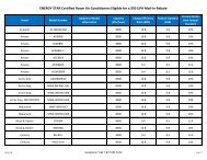
Appendix E-2.c.i Energy Plan 2004-2013 Follow-up Studies and ...
Appendix E-2.c.i Energy Plan 2004-2013 Follow-up Studies and ...
Appendix E-2.c.i Energy Plan 2004-2013 Follow-up Studies and ...

You also want an ePaper? Increase the reach of your titles
YUMPU automatically turns print PDFs into web optimized ePapers that Google loves.
Re-powering Study for the Northport <strong>and</strong> Port Jefferson Power Stations<br />
<strong>Appendix</strong> II Northport System Descriptions<br />
by recirculating water back to the HRSG LP drum. The recirculation line has a (spring-loaded) backpressure<br />
regulator valve <strong>and</strong> a gate valve.<br />
The feedwater pumps HP discharge line connects to the HRSG HP economizer inlet. The line has a<br />
branch for LP drum filling, a sample connection, a branch to the HRSG HP s<strong>up</strong>erheater attemperator, <strong>and</strong><br />
a branch to the main steam bypass valve. The HP s<strong>up</strong>erheater attemperator spray branch has a manual<br />
block valve, a flow element <strong>and</strong> transmitter for DCS flow indication. The main steam bypass<br />
des<strong>up</strong>erheater branch has a manual block valve.<br />
Downstream of the branch connections, the HP feedwater line connects to the HP economizer. The line<br />
contains a drum level control valve, with manual isolation valves <strong>and</strong> a manual bypass valve. Upstream<br />
of the control valve are a flow element with flow transmitter, a pressure transmitter, <strong>and</strong> a temperature<br />
indicator. The flow signal, along with drum level <strong>and</strong> steam flow signals, is used to position the drum<br />
level control valve. A pressure transmitter is provided downstream of the drum level control valve.<br />
A constant differential pressure is maintained across the HP drum level control valves by varying the<br />
speed of the feedwater pump.<br />
A motor operated on-off tight shutoff valve is provided downstream of the HP drum level control valve to<br />
prevent water leakage into the drum during start<strong>up</strong>.<br />
1.7.2 Intermediate Pressure Feedwater<br />
Each feedwater pump has an interstage bleed connection for IP feedwater s<strong>up</strong>ply to the HRSG IP<br />
economizer inlet. The connection is piped to a line containing a pressure gage, a check valve, <strong>and</strong> a gate<br />
valve. A branch line from the condensate system connects to the line to provide water to fill the IP drum.<br />
A branch from the line provides water for the HRSG reheater attemperator. This line has a gate valve <strong>and</strong><br />
a flow element <strong>and</strong> transmitter for DCS indication.<br />
Downstream of the branch connections there is a pressure transmitter. The IP feedwater line connects to<br />
the HRSG IP feedwater inlet connection. Downstream of the inlet connection, within the HRSG's<br />
vendors scope, there is a check valve, a manual gate valve, the IP economizer, a flow element with a flow<br />
transmitter, a temperature element, a drum level control valve with manual block <strong>and</strong> bypass valves, <strong>and</strong><br />
an air operated on-off tight shutoff valve. The flow signal, along with the drum level <strong>and</strong> steam flow<br />
signals, is used to position the drum level control valve.<br />
A branch line immediately downstream of the economizer <strong>and</strong> <strong>up</strong>stream of the drum level control valve<br />
provides the heating medium for the fuel gas performance heater.<br />
1.8 Fuel Gas<br />
Refer to PID-8-7A through 7D in <strong>Appendix</strong> III.<br />
The fuel gas delivered to Northport is AGA pipeline quality gas. No gas compressors are required.<br />
The fuel gas system (FGS) is designed to meet the requirements of the CTs including flow, pressure,<br />
temperature, moisture content, <strong>and</strong> cleanliness. To provide these requirements the FGS will include a<br />
pressure-reducing station, metering, filtration, gas heating, flow control, <strong>and</strong> scrubber with vent stack <strong>and</strong><br />
CH4 monitors to detect gas leakage.<br />
March 30, 2009 151