model osa-12 - Hill Phoenix
model osa-12 - Hill Phoenix
model osa-12 - Hill Phoenix

You also want an ePaper? Increase the reach of your titles
YUMPU automatically turns print PDFs into web optimized ePapers that Google loves.
DELI<br />
C A S E S<br />
MODEL: OSA & OSAG<br />
INSTALLATION & OPERATION<br />
HANDBOOK<br />
COMPONENT<br />
P052392H<br />
Rev. 14<br />
05/09
Welcome to the <strong>Hill</strong> PHOENIX display case family. We’re very pleased<br />
you joined us.<br />
This installation and operation handbook has been especially<br />
prepared for everyone involved with <strong>Hill</strong> PHOENIX display cases – owners,<br />
managers, installers and maintenance personnel.<br />
You’ll find this book different than traditional manuals. The most<br />
dramatic difference is the use of many more illustrated instructions to<br />
make it easier to read and to help you get the most from this innovative<br />
new design. When you follow the instructions you should expect<br />
remarkable performance, attractive fits and finish, and long case life.<br />
We are interested in your suggestions for improvement both in case<br />
design and in this handbook. Please call/write to:<br />
<strong>Hill</strong> PHOENIX<br />
Marketing Services Department<br />
1925 Ruffin Mill Rd.<br />
Colonial Heights, VA 23834<br />
Tel: 804-526-4455<br />
Fax: 804-526-7450<br />
or visit our web site at<br />
www.hillphoenix.com<br />
We wish you the very best in outstanding food merchandising and a long<br />
trouble-free operation.
TABLE OF CONTENTS<br />
GENERAL INFORMATION – PAGES 3 - 8<br />
General information, first step recommendations and case dimensional drawings.<br />
THE USE OF CASTERS – PAGE 9<br />
Cases roll on casters–general use and castor removal.<br />
LINE-UP – PAGES 10 - 11<br />
A ten step procedure for initial case lineup with illustrations.<br />
TRIM-OUT – PAGES <strong>12</strong> - 13<br />
A sixteen step procedure for trimming out cases with illustrations.<br />
REFRIGERATION PIPING – PAGE 14<br />
Diagrams show coil outlet and case controls location and other piping tips.<br />
PLUMBING – PAGE 15<br />
Information on drain connections.<br />
ELECTRICAL HOOKUP AND WIRING DIAGRAMS – PAGES 16 - 20<br />
Complete information on electrical connections.<br />
CASE OPERATION – PAGES 21 - 22<br />
Recommended settings for all case controls.<br />
DEFROST AND TEMPERATURE CONTROL – PAGE 23<br />
Defrost data. Sensor bulb locations.<br />
AIR FLOW AND PRODUCT LOADING – PAGE 24<br />
Air flow and load limits.<br />
USE AND MAINTENANCE – PAGES 25 - 28<br />
Cleaning and fan information.<br />
PARTS ORDERING – PAGES 29 - 31<br />
Replacement parts identification.<br />
NOTES – PAGES 32 - 34<br />
PRODUCT WARRANTY - Inside Back Cover<br />
1
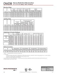
GENERAL INFORMATION<br />
DESCRIPTION OF CASES: Specifically covered in this manual is <strong>model</strong> OSA, service deli<br />
case and <strong>model</strong> OSAG, gravity service deli case.<br />
STORE CONDITIONS: <strong>Hill</strong> PHOENIX cases are designed to operate in an air conditioned store<br />
with a system that can maintain 75 O F (24 O C) store temperature and 55 percent (maximum)<br />
relative humidity (CRMA conditions). Case operation will be adversely affected by exposure to<br />
excessively high ambient temperatures and/or humidity.<br />
REFRIGERATION SYSTEM OPERATION: Air cooled condensing units require ventilation for<br />
efficient performance of condensers. Machine room temperatures must be a minimum of 65 O F<br />
in winter and a maximum of 95 O F in summer. Minimum condensing temperatures should be<br />
no less than 70 O F.<br />
RECEIVING CASES: Examine fixtures carefully for shipping damage and shortages. For information<br />
on shortages contact the Service Parts Department at 1-800-283-1109.<br />
APPARENT DAMAGE: A claim for obvious damage must be noted on the freight bill or express<br />
receipt and signed by the carriers agent, otherwise the carrier may refuse the claim.<br />
CONCEALED DAMAGE: If damage is not apparent until after the equipment is unpacked,<br />
retain all packing materials and submit a written request to the carrier for inspection within 15<br />
days of receipt of equipment.<br />
LOST ITEMS: This equipment has been carefully inspected to insure the highest level of quality.<br />
Any claim for lost items must be made to <strong>Hill</strong> PHOENIX within 48 hours of receipt of equipment.<br />
TECHNICAL SUPPORT: If any technical questions arise regarding a refrigerated display case<br />
contact our Customer Service Department in Richmond at 1-804-526-4455. For any questions<br />
regarding our refrigeration systems or electrical distribution centers contact our Customer<br />
Service Department in Conyers at 1-770-285-3200.<br />
CONTACTING FACTORY: Should you need to contact <strong>Hill</strong> PHOENIX regarding a specific fixture,<br />
be sure to know the case <strong>model</strong> number and serial number. This information is on the<br />
serial plate located on the rear panel of the case (see next page for details). Ask for a Service<br />
Parts Representative at 1-804-526-4455.<br />
3
GENERAL INFORMATION<br />
Amp Plate &<br />
Serial Plate<br />
Location<br />
49 1/16 in<br />
[<strong>12</strong>4.6 cm]<br />
54 7/16 in<br />
[138.3 cm]<br />
5 13/16 in [14.7 cm]<br />
38 5/16 in<br />
[97.3 cm]<br />
REAR SLIDING DOORS<br />
FLAT REAR SILL<br />
(OPTIONAL)<br />
32 3/4 in<br />
[83.2 cm]<br />
11 in<br />
[28.0 cm]<br />
4 5/8 in [11.7 cm]<br />
5 13/16 in [14.7 cm]<br />
34 1/2 in<br />
[87.6 cm]<br />
JUNCTION BOX<br />
(STANDARD)<br />
21 1/2 in<br />
[54.6 cm]<br />
25 9/16 in [64.9 cm]<br />
28 1/16 in [71.2 cm]<br />
NOTES:<br />
10 5/16 in<br />
[26.1 cm]<br />
30 1/2 in<br />
[77.5 cm]<br />
28 3/8 in [72.0 cm]*<br />
35 11/16 in [90.7 cm]<br />
38 5/16 in [97.3 cm]<br />
49 1/16 in [<strong>12</strong>4.6 cm]<br />
21 1/2 in<br />
[54.6 cm]<br />
**<br />
PLENUM<br />
1 1/2" PVC DRAIN<br />
CONNECTION<br />
(6', 8', <strong>12</strong>' cases)<br />
ELECTRICAL<br />
32 3/16 in [81.8 cm]<br />
COIL<br />
STANDARD REAR SILL<br />
FLAT REAR SILL<br />
(OPTIONAL)<br />
FRONT OF CASE<br />
4<br />
C L<br />
48 in [<strong>12</strong>1.9 cm] {4' case}<br />
72 in [182.9 cm] {6' case}<br />
96 in [243.8 cm] {8' case}<br />
144 in [365.8 cm] {<strong>12</strong>' case}<br />
DOUBLE ROW CANOPY LIGHTS<br />
(OPTIONAL)<br />
22 in<br />
[55.9 cm]<br />
REFRIGERATION<br />
(4' cases only)<br />
1 1/2" PVC DRAIN<br />
CONNECTION<br />
(4' cases only)<br />
26 3/4 in<br />
[68.0 cm]<br />
* STUB-UP AREA<br />
** RECOMMENDED STUB-UP CENTERLINE FOR ELECTRICAL AND HUB DRAINS<br />
� FRONT, REAR AND TOP SILL HEIGHTS VARY WITH BASEFRAME HEIGHT<br />
� ENDS ADD APPROXIMATELY 1 INCH TO CASE HEIGHT<br />
� SUCTION LINE - 7/8", LIQUID LINE - 1/2"<br />
� AVAILABLE SHELF SIZES: 10" & <strong>12</strong>"<br />
4 5/8 in [11.7 cm]<br />
MODEL<br />
OSA<br />
(11” BASEFRAME)<br />
28 9/16 in<br />
[72.5 cm]<br />
REFRIGERATION<br />
(6', 8', <strong>12</strong>' cases)<br />
1 1/2 in [3.8 cm]<br />
{END}<br />
34 9/16 in<br />
[87.7 cm]<br />
8 11/16 in [22.1 cm]<br />
<strong>12</strong> in [30.5 cm]
Amp Plate &<br />
Serial Plate<br />
Location<br />
49 1/16 in<br />
[<strong>12</strong>4.6 cm]<br />
5 13/16 in [14.7 cm]<br />
42 7/16 in<br />
[107.8 cm]<br />
50 5/16 in<br />
[<strong>12</strong>7.8 cm]<br />
37 9/16 in<br />
[95.4 cm]<br />
35 1/16 in<br />
[89.1 cm]<br />
JUNCTION BOX<br />
(STANDARD)<br />
REAR SLIDING DOORS<br />
FLAT REAR SILL<br />
(OPTIONAL)<br />
28 5/8 in<br />
[72.6 cm]<br />
7 in [17.8 cm]<br />
4 5/8 in [11.7 cm]<br />
5 13/16 in [14.7 cm]<br />
ELECTRICAL<br />
25 9/16 in [64.9 cm]<br />
28 1/16 in [71.2 cm]<br />
1 1/2" PVC DRAIN<br />
CONNECTION<br />
(6', 8', <strong>12</strong>' cases)<br />
NOTES:<br />
21 1/2 in<br />
[54.6 cm]<br />
10 5/16 in<br />
[26.1 cm]<br />
30 1/2 in<br />
[77.5 cm]<br />
PLENUM<br />
37 9/16 in [95.4 cm]<br />
42 7/16 in [107.8 cm]<br />
49 1/16 in [<strong>12</strong>4.6 cm]<br />
39 9/16 in<br />
[100.5 cm]<br />
**<br />
32 3/16 in [81.8 cm]<br />
4 in [10.2 cm]*<br />
C L<br />
FRONT OF CASE<br />
5<br />
COIL<br />
48 in [<strong>12</strong>1.9 cm] {4' case}<br />
72 in [182.9 cm] {6' case}<br />
96 in [243.8 cm] {8' case}<br />
144 in [365.8 cm] {<strong>12</strong>' case}<br />
STANDARD REAR SILL<br />
FLAT REAR SILL<br />
(OPTIONAL)<br />
REFRIGERATION<br />
(4' cases only)<br />
1 1/2" PVC DRAIN<br />
CONNECTION<br />
(4' cases only)<br />
DOUBLE ROW CANOPY LIGHTS<br />
(OPTIONAL)<br />
17 7/8 in<br />
[45.4 cm]<br />
22 5/8 in<br />
[57.5 cm]<br />
* STUB-UP AREA<br />
** RECOMMENDED STUB-UP CENTERLINE FOR ELECTRICAL AND HUB DRAINS<br />
� FRONT, REAR AND TOP SILL HEIGHTS VARY WITH BASEFRAME HEIGHT<br />
� ENDS ADD APPROXIMATELY 1 INCH TO CASE HEIGHT<br />
� SUCTION LINE - 7/8", LIQUID LINE - 1/2"<br />
� AVAILABLE SHELF SIZES: 10" & <strong>12</strong>"<br />
MODEL<br />
OSA<br />
(7” BASEFRAME)<br />
4 5/8 in [11.7 cm]<br />
28 9/16 in<br />
[72.5 cm]<br />
34 9/16 in<br />
[87.7 cm]<br />
REFRIGERATION<br />
(6', 8', <strong>12</strong>' cases)<br />
1 1/2 in [3.8 cm]<br />
{END}<br />
8 11/16 in [22.1 cm]<br />
<strong>12</strong> in [30.5 cm]<br />
39 3/8 in<br />
[100.0 cm]
GENERAL INFORMATION<br />
Amp Plate &<br />
Serial Plate<br />
Location<br />
49 1/16 in<br />
[<strong>12</strong>4.6 cm]<br />
5 13/16 in [14.7 cm]<br />
38 5/16 in<br />
[97.3 cm]<br />
34 1/2 in<br />
[87.6 cm]<br />
54 7/16 in<br />
[138.3 cm]<br />
JUNCTION BOX<br />
(STANDARD)<br />
REAR SLIDING DOORS<br />
FLAT REAR SILL<br />
(OPTIONAL)<br />
32 3/4 in<br />
[83.2 cm]<br />
SECOND ROW OF<br />
CORNICE LIGHTS<br />
(OPTIONAL)<br />
11 in<br />
[28.0 cm]<br />
4 5/8 in [11.7 cm]<br />
5 13/16 in [14.7 cm]<br />
25 9/16 in [64.9 cm]<br />
28 1/16 in [71.2 cm]<br />
NOTES:<br />
21 1/2 in<br />
[54.6 cm]<br />
21 1/2 in<br />
[54.6 cm]<br />
**<br />
1 1/2" PVC DRAIN<br />
CONNECTION<br />
(6', 8', <strong>12</strong>' cases)<br />
10 5/16 in<br />
[26.1 cm]<br />
24 5/16 in<br />
[61.8 cm]<br />
PLENUM<br />
COIL<br />
LOUVER<br />
6<br />
COIL<br />
28 3/8 in [72.0 cm]*<br />
35 11/16 in [90.7 cm]<br />
38 5/16 in [97.3 cm]<br />
49 1/16 in [<strong>12</strong>4.6 cm]<br />
ELECTRICAL<br />
32 3/16 in [81.8 cm]<br />
STANDARD REAR SILL<br />
FLAT REAR SILL<br />
(OPTIONAL)<br />
C L<br />
FRONT OF CASE<br />
48 in [<strong>12</strong>1.9 cm] {4' case}<br />
72 in [182.9 cm] {6' case}<br />
96 in [243.8 cm] {8' case}<br />
144 in [365.8 cm] {<strong>12</strong>' case}<br />
REFRIGERATION<br />
(4' cases only)<br />
1 1/2" PVC DRAIN<br />
CONNECTION<br />
(4' cases only)<br />
SINGLE SHELF ONLY<br />
AVAILABLE ON THIS<br />
MODEL<br />
(Only with forced air coil)<br />
22 in<br />
[55.9 cm]<br />
26 3/4 in<br />
[68.0 cm]<br />
* STUB-UP AREA<br />
** RECOMMENDED STUB-UP CENTERLINE FOR ELECTRICAL AND HUB DRAINS<br />
� FRONT, REAR AND TOP SILL HEIGHTS VARY WITH BASEFRAME HEIGHT<br />
� ENDS ADD APPROXIMATELY 1 INCH TO CASE HEIGHT<br />
� SUCTION LINE - 7/8", LIQUID LINE - 1/2"<br />
� AVAILABLE SHELF SIZES: 10" & <strong>12</strong>"<br />
4 5/8 in [11.7 cm]<br />
MODEL<br />
OSAG<br />
(11” BASEFRAME)<br />
28 9/16 in<br />
[72.5 cm]<br />
REFRIGERATION<br />
(6', 8', <strong>12</strong>' cases)<br />
1 1/2 in [3.8 cm]<br />
{END}<br />
34 9/16 in<br />
[87.7 cm]<br />
8 11/16 in [22.1 cm]<br />
<strong>12</strong> in [30.5 cm]
Amp Plate &<br />
Serial Plate<br />
Location<br />
49 1/16 in<br />
[<strong>12</strong>4.6 cm]<br />
50 5/16 in<br />
[<strong>12</strong>7.8 cm]<br />
5 13/16 in [14.7 cm]<br />
42 7/16 in<br />
[107.8 cm]<br />
37 9/16 in<br />
[95.4 cm]<br />
35 1/16 in<br />
[89.1 cm]<br />
JUNCTION BOX<br />
(STANDARD)<br />
REAR SLIDING DOORS<br />
FLAT REAR SILL<br />
(OPTIONAL)<br />
28 5/8 in<br />
[72.6 cm]<br />
7 in [17.8 cm]<br />
4 5/8 in [11.7 cm]<br />
5 13/16 in [14.7 cm]<br />
SECOND ROW OF<br />
CORNICE LIGHTS<br />
(OPTIONAL)<br />
ELECTRICAL<br />
25 9/16 in [64.9 cm]<br />
28 1/16 in [71.2 cm]<br />
21 1/2 in<br />
[54.6 cm]<br />
1 1/2" PVC DRAIN<br />
CONNECTION<br />
(6', 8', <strong>12</strong>' cases)<br />
NOTES:<br />
10 5/16 in<br />
[26.1 cm]<br />
24 5/16 in<br />
[61.8 cm]<br />
PLENUM<br />
LOUVER<br />
7<br />
32 3/16 in [81.8 cm]<br />
COIL<br />
4 in [10.2 cm]*<br />
37 9/16 in [95.4 cm]<br />
42 7/16 in [107.8 cm]<br />
49 1/16 in [<strong>12</strong>4.6 cm]<br />
39 9/16 in<br />
[100.5 cm]<br />
**<br />
C L<br />
FRONT OF CASE<br />
48 in [<strong>12</strong>1.9 cm] {4' case}<br />
72 in [182.9 cm] {6' case}<br />
96 in [243.8 cm] {8' case}<br />
144 in [365.8 cm] {<strong>12</strong>' case}<br />
STANDARD REAR SILL<br />
FLAT REAR SILL<br />
(OPTIONAL)<br />
REFRIGERATION<br />
(4' cases only)<br />
1 1/2" PVC DRAIN<br />
CONNECTION<br />
(4' cases only)<br />
SINGLE SHELF ONLY<br />
AVAILABLE ON THIS<br />
MODEL<br />
(Only with forced air coil)<br />
17 7/8 in<br />
[45.4 cm]<br />
22 5/8 in<br />
[57.5 cm]<br />
* STUB-UP AREA<br />
** RECOMMENDED STUB-UP CENTERLINE FOR ELECTRICAL AND HUB DRAINS<br />
� FRONT, REAR AND TOP SILL HEIGHTS VARY WITH BASEFRAME HEIGHT<br />
� ENDS ADD APPROXIMATELY 1 INCH TO CASE HEIGHT<br />
� SUCTION LINE - 7/8", LIQUID LINE - 1/2"<br />
� AVAILABLE SHELF SIZES: 10" & <strong>12</strong>"<br />
MODEL<br />
OSAG<br />
(7” BASEFRAME)<br />
4 5/8 in [11.7 cm]<br />
28 9/16 in<br />
[72.5 cm]<br />
34 9/16 in<br />
[87.7 cm]<br />
REFRIGERATION<br />
(6', 8', <strong>12</strong>' cases)<br />
1 1/2 in [3.8 cm]<br />
{END}<br />
8 11/16 in [22.1 cm]<br />
<strong>12</strong> in [30.5 cm]<br />
39 3/8 in<br />
[100.0 cm]
GENERAL INFORMATION<br />
4"<br />
4"<br />
31 11/16"<br />
4"<br />
31 11/16"<br />
4"<br />
31 11/16"<br />
4"<br />
31 11/16"<br />
4"<br />
31 11/16"<br />
4' CASE<br />
6' CASE<br />
8' CASE<br />
47 1/4"<br />
FRONT OF CASE<br />
49 1/8"<br />
<strong>12</strong>' CASE<br />
11" BASEFRAME<br />
<strong>12</strong>' CASE<br />
7" BASEFRAME<br />
44 5/8"<br />
71 1/4"<br />
FRONT OF CASE<br />
6"<br />
95 1/4"<br />
FRONT OF CASE<br />
73 1/8"<br />
92 5/8"<br />
4"<br />
143 1/4"<br />
FRONT OF CASE<br />
6" 6"<br />
143 1/4"<br />
FRONT OF CASE<br />
4"<br />
6" 4"<br />
8<br />
4"<br />
BASEHORSE<br />
LOCATIONS FOR<br />
MODEL<br />
OSA & OSAG
CASES<br />
MOVE ON<br />
CASTERS<br />
FOR EASIER INSTALLATION<br />
Cases are manufactured and shipped to stores with<br />
casters installed on the base frame to make the job of<br />
moving cases easier for everyone involved with the<br />
manufacturing, shipping and installation process.<br />
1 2<br />
ROLL OUT OF TRUCK. When there is a truck - level<br />
delivery dock, cases may be rolled directly from the<br />
truck to the store floor. [CAUTION] If skid boards are<br />
required to unload cases, casters should be removed<br />
prior to sliding them down the skid; after which they<br />
can be reinstalled on case.<br />
3 4<br />
REMOVE COTTER PIN. Removing the casters is<br />
easy. Simply flatten and hammer out cotter pins then<br />
lift the case with “J” bar, and the casters will fall off.<br />
[CAUTION] Make certain hands are out of the way.<br />
9<br />
Casters not only speed up the process, but they also<br />
reduce the chance of damage from raising and lowering<br />
cases with ”J” bar to place them on dollies, skates<br />
or rollers. In most situations, one or two persons can<br />
move the case with ease.<br />
ROLL TO LINEUP POSITION. Casters may remain in<br />
place to move the cases to staging areas around the<br />
store, prior to final installation. When ready for final<br />
line-up, roll the case to set position, then remove<br />
casters.<br />
CASTERS MAY BE DISCARDED.
LINE UP<br />
Consult With General Contractor<br />
1<br />
Ask the general contractor if there have<br />
been changes in the building dimensions<br />
since the print you are using was<br />
issued. Also, ask the points of reference<br />
from which you should take<br />
dimensions to locate the cases.<br />
Level Floor. Use Laser Transit<br />
4<br />
Leveling is necessary to assure proper<br />
case alignment. Locate highest point<br />
on chalk line as reference for<br />
determining height of shim-pack<br />
levelers. A laser transit is recommended<br />
for precision and requires just one<br />
person.<br />
Snap Chalk Lines<br />
2<br />
Mark floor where cases are to be<br />
located for the entire lineup.<br />
Set Shims On Basehorse Locations<br />
5<br />
Locate basehorse positions along chalk<br />
lines. Spot shim packs at each basehorse<br />
location.<br />
10<br />
BASE RAIL BASE RAIL<br />
Snap Lines On Base Rail<br />
Locations<br />
3<br />
Snap lines where base rails are positioned,<br />
not the front or back edges of<br />
the cases. See case cross section<br />
drawing, pages 4-7 for rail location<br />
dimensions.<br />
Position First Case In Lineup, Remove<br />
Casters, Level<br />
6<br />
Roll first case into position. Raise case<br />
from end under cross support using<br />
“J” bar. Remove cotter pins and casters.<br />
[CAUTION! Keep hands from<br />
under case] Level case on shims.
Position Next Case In Line Up<br />
7<br />
Roll case approximately 2’ from adjoining<br />
case. Remove casters on the end<br />
nearest to the next case. Allow casters<br />
to remain on opposite end to assist in<br />
pushing cases together - then remove<br />
them.<br />
4<br />
3<br />
5<br />
Bolt Cases Together Using Bolt Holes<br />
Provided<br />
10<br />
margins are equal; do not over tighten.<br />
Push cases tightly together. Bolt cases<br />
together through the five holes provided<br />
in the “C” frame and pipe chase as<br />
shown in illustration. Tighten until all<br />
2<br />
1<br />
Remove Shipping Accessories From<br />
Case. Add Sealant.<br />
8<br />
Remove anything from the case that<br />
may interfere with case joining. Apply<br />
the foam tape that is shipped loose in<br />
the case to the end breakers on each<br />
side of the case. Run a bead of sealant<br />
around the entire end before pushing<br />
cases tightly together.<br />
11<br />
Loosen Bumper And Cornice<br />
9<br />
Loosen screws on master bumper.<br />
Move bumper joint to a position for<br />
sliding between adjoining case bumper.<br />
Ask about our case installation video available by request through your local <strong>Hill</strong> PHOENIX Sales or Field Service<br />
Representative. Spanish version available.<br />
CAULK<br />
FOAM TAPE
TRIM OUT<br />
Now that cases have been<br />
positioned and leveled, you<br />
may proceed to trim-out case<br />
lineup. Trim parts have been<br />
designed to be applied easily<br />
with only a small number of<br />
fasteners required. Most<br />
external parts are adjustable<br />
to achieve almost invisible,<br />
snug-fitting joints and a high<br />
level of excellence in fit and<br />
finish.<br />
3<br />
Slide bumper joint to the center of the<br />
joint between the two cases. Use screw<br />
driver in hole provided.<br />
6<br />
Seal joints along pipe chase seam with<br />
the caulk provided.<br />
1<br />
Tighten all joint bolts. Draw up tightly, but<br />
do not over tighten.<br />
4<br />
Slide master bumper left or right to close<br />
seam as required. Bumper joint neatly<br />
finishes any gap that may remain.<br />
PIPE<br />
CHASE<br />
7<strong>12</strong><br />
ACRYLIC<br />
TAPE<br />
Apply acrylic tape over pipe chase seam.<br />
Tape is found with the ship loose items<br />
and acts as a watershed preventing water<br />
from settling in case joint.<br />
2<br />
Adjust polymer master bumper joints, if<br />
required. First loosen bumper screws.<br />
5<br />
Close seam where bumper joins case<br />
end. Bumper joint closes seam that may<br />
develop if master bumper is moved away<br />
from end to close case-to-case joint<br />
seam.<br />
LOWER<br />
REAR<br />
BAFFLE<br />
PLENUM<br />
COVER<br />
DECK PAN<br />
PLENUM<br />
COIL<br />
8<br />
Install plenum covers under deck pans.<br />
The plenum covers are shipped loose in<br />
the case and are installed between the<br />
lower rear baffle and the fan plenum.
9<br />
Close joints of front panel. The panel is<br />
slotted on the bottom to allow left or right<br />
adjustment as required.<br />
TOP SILL<br />
JOINT<br />
TOP SILL<br />
GLASS<br />
PRESSURE<br />
BAR<br />
<strong>12</strong><br />
Install top sill joint. The top sill joints are<br />
shipped loose in the case. The front lip of<br />
the joint fits into the crevice between the<br />
top sill and the glass pressure bar. The<br />
rear lip is attached to the back of the case<br />
10 11<br />
for cases with ends.<br />
Install curved front panel joint (if cases<br />
come equipped with curved front panels).<br />
Curved panel joints are shipped loose in<br />
the case and are attached with the screws<br />
provided. Wide joints (1”) are for case-tocase<br />
joining and narrow joints (1/2”) are<br />
Attach lower front panel (for cases on 11”<br />
baseframes). Slots and tabs are designed<br />
for easy installation without fasteners.<br />
The lower front panel is slotted to allow<br />
adjustment left or right as required.<br />
13<br />
Install rear sill joint. The rear sill joints are Attach the<br />
14<br />
“J” rail. Attach the “J” rail to<br />
shipped loose in the case. The bottom the base horses with the screws pro-<br />
portion of the joint should be slid on the vided.<br />
rear sill first then the top lip fits between<br />
the rear sill and the mullion. Secure the<br />
with the screws provided. joint underneath the rear sill with the<br />
screws provided.<br />
LOWER FRONT<br />
PANEL<br />
KICKPLATE<br />
15<br />
Insert kickplate into “J” rail. Slide the<br />
kickplate up and behind the lower front<br />
panel bracket then down on the “J” rail.<br />
“J” RAIL<br />
MULLION<br />
16<br />
13<br />
CURVED FRONT<br />
PANEL<br />
CURVED FRONT<br />
PANEL JOINT<br />
REAR SILL<br />
REAR SILL<br />
JOINT<br />
Insert nose bumper into master bumper<br />
channel. Roll nose bumper into channel<br />
along entire lineup (up to 96’). We recommend<br />
that the nose bumper be left in the<br />
store 24 hours before installing.<br />
DO NOT STRETCH the bumper during<br />
installation as it will shrink to its original<br />
length and leave a gap.<br />
BASE HORSE<br />
“J” RAIL<br />
NOTE: An easy technique for one<br />
person is to press against nose bumper<br />
with leg as you guide bumper into<br />
channel with a screen spline. Insert<br />
bottom first.
REFRIGERATION PIPING<br />
Refrigeration components and the coil<br />
outlet hole are located to provide the best access<br />
for installation and maintenance. As the diagrams<br />
below indicates, the coil outlet hole is<br />
positioned forward on the right hand side of the<br />
case, fully visible in front of the fan plenum.<br />
The expansion valve and other controls<br />
are located on the left-hand side of the case and<br />
are accessible without lifting the fan plenum.<br />
The controls cluster may be reached by lifting<br />
only the left hand deck pan minimizing the need<br />
to unload product.<br />
A suction stop solenoid installed in the<br />
5 13/16 in [14.7 cm]<br />
49 1/16 in<br />
[<strong>12</strong>4.6 cm]<br />
PIPING<br />
38 5/16 in<br />
[97.3 cm]<br />
21 1/2 in<br />
[54.6 cm]<br />
**<br />
STANDARD REAR SILL<br />
FLAT REAR SILL<br />
(OPTIONAL)<br />
C L<br />
FRONT OF CASE<br />
REFRIGERATION<br />
(4' cases only)<br />
4 5/8 in [11.7 cm]<br />
48 in [<strong>12</strong>1.9 cm] {4' case}<br />
72 in [182.9 cm] {6' case}<br />
96 in [243.8 cm] {8' case}<br />
NOTES:<br />
144 in [365.8 cm] {<strong>12</strong>' case}<br />
** RECOMMENDED STUB-UP CENTERLINE FOR ELECTRICAL AND HUB DRAINS<br />
� SUCTION LINE - 7/8", LIQUID LINE - 1/2"<br />
MODEL OSA & OSAG<br />
(11” BASEFRAME)<br />
OSAG COIL PIPING<br />
UPPER<br />
COIL<br />
LOWER<br />
COIL<br />
TOP COIL<br />
28 9/16 in<br />
[72.5 cm]<br />
REFRIGERATION<br />
(6', 8', <strong>12</strong>' cases)<br />
1 1/2 in [3.8 cm]<br />
{END}<br />
8 11/16 in [22.1 cm]<br />
14<br />
top coil’s suction line is required for this case.<br />
Control of the solenoid can be achieved with a<br />
thermostat at the case or an external controller.<br />
A liquid line solenoid alone will not allow the<br />
case to cycle properly and is not recommended<br />
for control of this case. The thermostat<br />
probe should be located on the inlet of the top<br />
coil. The cut out temperature should be set to<br />
30 o F and the cut in temperature should be set<br />
to 35 o F. These are recommended starting values<br />
and may need to be adjusted based on<br />
store conditions.<br />
If it becomes necessary to penetrate the<br />
case bottom for any reason, make certain it is<br />
sealed afterward with canned-foam sealant<br />
and white RTV.<br />
5 13/16 in [14.7 cm]<br />
34 9/16 in<br />
[87.7 cm]<br />
37 9/16 in<br />
[95.4 cm]<br />
42 7/16 in<br />
[107.8 cm]<br />
49 1/16 in<br />
[<strong>12</strong>4.6 cm]<br />
OSAG TOP COIL PIPING<br />
INLET LINE<br />
SUCTION LINE<br />
39 9/16 in<br />
[100.5 cm]<br />
**<br />
C L<br />
FRONT OF CASE<br />
STANDARD REAR SILL<br />
FLAT REAR SILL<br />
(OPTIONAL)<br />
REFRIGERATION<br />
(4' cases only)<br />
48 in [<strong>12</strong>1.9 cm] {4' case}<br />
72 in [182.9 cm] {6' case}<br />
96 in [243.8 cm] {8' case}<br />
NOTES:<br />
144 in [365.8 cm] {<strong>12</strong>' case}<br />
** RECOMMENDED STUB-UP CENTERLINE FOR ELECTRICAL AND HUB DRAINS<br />
� SUCTION LINE - 7/8", LIQUID LINE - 1/2"<br />
MODEL OSA & OSAG<br />
(7” BASEFRAME)<br />
4 5/8 in [11.7 cm]<br />
28 9/16 in<br />
[72.5 cm]<br />
34 9/16 in<br />
[87.7 cm]<br />
REFRIGERATION<br />
(6', 8', <strong>12</strong>' cases)<br />
1 1/2 in [3.8 cm]<br />
{END}<br />
8 11/16 in [22.1 cm]<br />
REMOVE SHIPPING BLOCKS<br />
REMOVE THE SHIPPING BLOCKS THAT<br />
PROTECT THE REFRIGERATION LINES<br />
DURING SHIPMENT BEFORE<br />
OPERATING THE CASE.
The drain outlet is located front and<br />
center of the cases for convenient access and<br />
is specially molded out of ABS material. The<br />
“P” trap, furnished with the case, is constructed<br />
of schedule 40 PVC pipe. Care should be<br />
given to assure that all connections are water<br />
tight and sealed with the appropriate PVC or<br />
ABS cement.<br />
The drain lines can be run left or right of<br />
the tee with the proper pitch to satisfy local<br />
drainage requirements.<br />
5 13/16 in [14.7 cm]<br />
49 1/16 in<br />
[<strong>12</strong>4.6 cm]<br />
38 5/16 in<br />
[97.3 cm]<br />
21 1/2 in<br />
[54.6 cm]<br />
**<br />
1 1/2" PVC DRAIN<br />
CONNECTION<br />
(6', 8', <strong>12</strong>' cases)<br />
STANDARD REAR SILL<br />
FLAT REAR SILL<br />
(OPTIONAL)<br />
C L<br />
FRONT OF CASE<br />
1 1/2" PVC DRAIN<br />
CONNECTION<br />
(4' cases only)<br />
48 in [<strong>12</strong>1.9 cm] {4' case}<br />
72 in [182.9 cm] {6' case}<br />
96 in [243.8 cm] {8' case}<br />
144 in [365.8 cm] {<strong>12</strong>' case}<br />
NOTES:<br />
** RECOMMENDED STUB-UP CENTERLINE FOR ELECTRICAL AND HUB DRAINS<br />
MODEL OSA & OSAG<br />
(11” BASEFRAME)<br />
4 5/8 in [11.7 cm]<br />
34 9/16 in<br />
[87.7 cm]<br />
1 1/2 in [3.8 cm]<br />
{END}<br />
<strong>12</strong> in [30.5 cm]<br />
HOW TO REMOVE KICKPLATE<br />
LIFT UP FROM “J”<br />
RAIL AND PULL OUT<br />
KICKPLATE<br />
“J” RAIL<br />
15<br />
PLUMBING<br />
The kickplate is shipped loose with the<br />
case for field installation, therefore you should<br />
have open access to the drain line area.<br />
If the kickplate has been installed, you<br />
will find it very easy to remove. See instructions<br />
below, or the trim out section of this<br />
manual on page 13.<br />
5 13/16 in [14.7 cm]<br />
37 9/16 in<br />
[95.4 cm]<br />
42 7/16 in<br />
[107.8 cm]<br />
49 1/16 in<br />
[<strong>12</strong>4.6 cm]<br />
1 1/2" PVC DRAIN<br />
CONNECTION<br />
(6', 8', <strong>12</strong>' cases)<br />
39 9/16 in<br />
[100.5 cm]<br />
**<br />
C L<br />
FRONT OF CASE<br />
STANDARD REAR SILL<br />
FLAT REAR SILL<br />
(OPTIONAL)<br />
1 1/2" PVC DRAIN<br />
CONNECTION<br />
(4' cases only)<br />
48 in [<strong>12</strong>1.9 cm] {4' case}<br />
72 in [182.9 cm] {6' case}<br />
96 in [243.8 cm] {8' case}<br />
NOTES:<br />
144 in [365.8 cm] {<strong>12</strong>' case}<br />
** RECOMMENDED STUB-UP CENTERLINE FOR ELECTRICAL AND HUB DRAINS<br />
MODEL OSA & OSAG<br />
(7” BASEFRAME)<br />
11” BASEFRAME 7” BASEFRAME<br />
4 5/8 in [11.7 cm]<br />
39 3/8 in<br />
[100.0 cm]<br />
1 1/2 in [3.8 cm]<br />
{END}<br />
<strong>12</strong> in [30.5 cm]
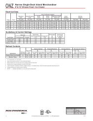
ELECTRICAL HOOKUP<br />
Electrical hookups for the OSA and OSAG<br />
are made to a junction box located underneath the<br />
case on the bottom left hand front. The light ballast<br />
for the case are located in one of two locations.<br />
For cases that have an 11” baseframe the ballasts<br />
are located under the rear sill behind a removable<br />
access cover as shown below. For cases with a 7”<br />
baseframe the ballasts are located in a sliding ballast<br />
tray on the bottom left front of the case, also<br />
shown below.<br />
49 1/16 in<br />
[<strong>12</strong>4.6 cm]<br />
5 13/16 in [14.7 cm]<br />
38 5/16 in<br />
[97.3 cm]<br />
34 1/2 in<br />
[87.6 cm]<br />
JUNCTION BOX<br />
(STANDARD)<br />
WIRING NUMBERS AND COLORS<br />
EVAPORATOR FANS, <strong>12</strong>0 VOLT<br />
LIGHTS, <strong>12</strong>0 VOLT<br />
21 1/2 in<br />
[54.6 cm]<br />
**<br />
25 9/16 in [64.9 cm]<br />
28 1/16 in [71.2 cm]<br />
ELECTRICAL<br />
COMPONENT WIRE NUMBER COLOR CODING<br />
TEMPERATURE CONTROL, <strong>12</strong>0 VOLT<br />
STANDARD REAR SILL<br />
FLAT REAR SILL<br />
(OPTIONAL)<br />
FRONT OF CASE<br />
48 in [<strong>12</strong>1.9 cm] {4' case}<br />
72 in [182.9 cm] {6' case}<br />
96 in [243.8 cm] {8' case}<br />
NOTES:<br />
144 in [365.8 cm] {<strong>12</strong>' case}<br />
** RECOMMENDED STUB-UP CENTERLINE FOR ELECTRICAL AND HUB DRAIN<br />
DEFROST TERMINATION CONTROL, <strong>12</strong>0 VOLT<br />
3<br />
4<br />
11<br />
<strong>12</strong><br />
ANTI-CONDENSATE HEATERS, <strong>12</strong>0 VOLT 13<br />
14<br />
19<br />
20<br />
21<br />
DEFROST HEATERS, 208/240 VOLTS L1<br />
L2<br />
C L<br />
MODEL OSA & OSAG<br />
(11” BASEFRAME)<br />
4 5/8 in [11.7 cm]<br />
1 1/2 in [3.8 cm]<br />
{END}<br />
23<br />
16<br />
5 13/16 in [14.7 cm]<br />
35 1/16 in<br />
[89.1 cm]<br />
37 9/16 in<br />
[95.4 cm]<br />
42 7/16 in<br />
[107.8 cm]<br />
49 1/16 in<br />
[<strong>12</strong>4.6 cm]<br />
JUNCTION BOX<br />
(STANDARD)<br />
WHITE<br />
BLACK<br />
WHITE<br />
BLACK<br />
WHITE<br />
BLACK<br />
YELLOW<br />
YELLOW<br />
PURPLE<br />
ORANGE<br />
RED<br />
BLUE<br />
EQUIPMENT GROUNDING CONDUCTOR -<br />
GREEN<br />
In order to access the sliding ballast<br />
tray, the rear panel must be removed. Simply<br />
lift up the back panel and then pull it out, see<br />
diagram below.<br />
For case-to-case wiring, run “greenfield”,<br />
or other conduit, between junction<br />
boxes. When connecting to the junction box<br />
field connections should be made on the right<br />
hand side of the box to allow more room inside<br />
for wire connecting.<br />
ELECTRICAL<br />
25 9/16 in [64.9 cm]<br />
28 1/16 in [71.2 cm]<br />
39 9/16 in<br />
[100.5 cm]<br />
**<br />
C L<br />
FRONT OF CASE<br />
STANDARD REAR SILL<br />
FLAT REAR SILL<br />
(OPTIONAL)<br />
48 in [<strong>12</strong>1.9 cm] {4' case}<br />
72 in [182.9 cm] {6' case}<br />
96 in [243.8 cm] {8' case}<br />
NOTES:<br />
144 in [365.8 cm] {<strong>12</strong>' case}<br />
** RECOMMENDED STUB-UP CENTERLINE FOR ELECTRICAL AND HUB DRAINS<br />
MODEL OSA & OSAG<br />
(7” BASEFRAME)<br />
STANDARD REAR<br />
SILL<br />
REAR SILL<br />
REMOVABLE<br />
COVER<br />
BALLAST<br />
LOCATION<br />
FLAT REAR<br />
SILL<br />
REAR PANEL<br />
(Lift Up and<br />
Remove)<br />
BALLAST<br />
LOCATION<br />
4 5/8 in [11.7 cm]<br />
1 1/2 in [3.8 cm]<br />
{END}<br />
BALLAST<br />
TRAY
WIRING DIAGRAMS- MODEL<br />
OSA-4’<br />
OSAG-4’<br />
17
WIRING DIAGRAMS- MODEL<br />
OSA-6’<br />
OSAG-6’<br />
18
WIRING DIAGRAMS- MODEL<br />
OSA-8’<br />
OSAG-8’<br />
19
WIRING DIAGRAMS-<br />
20<br />
MODEL<br />
OSA-<strong>12</strong>’<br />
OSAG-<strong>12</strong>’
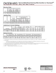
CASE OPERATION<br />
American Style Curved Glass Service Deli Merchandiser<br />
OSA - 4’, 6’, 8’ & <strong>12</strong>’ american style full service<br />
Electrical Data<br />
Model<br />
OSA<br />
4’<br />
6’<br />
8’<br />
<strong>12</strong>’<br />
Lighting Data<br />
Model<br />
OSA<br />
Model<br />
OSA w/ Shelf Lights<br />
OSA w/o Shelf Lights<br />
Fans per<br />
Case<br />
2<br />
2<br />
3<br />
4<br />
BTUH/ft 1<br />
320<br />
290<br />
3 Not recommended on this <strong>model</strong> due to long defrost time.<br />
4 NOTE: - - - not an option on this case <strong>model</strong>.<br />
Medium Temperature Defrost Schedule<br />
No. Per Day Hours<br />
1 <strong>12</strong> midnight<br />
2 <strong>12</strong> am - <strong>12</strong> pm<br />
3 6 am - 2 pm - 10 pm<br />
4 <strong>12</strong> - 6 am - <strong>12</strong> - 6 pm<br />
Standard Fans<br />
Amps<br />
0.68<br />
0.68<br />
1.02<br />
1.36<br />
<strong>12</strong>0 Volts<br />
All measurements are taken per CRMA specifications.<br />
Watts<br />
34<br />
34<br />
51<br />
68<br />
Guidelines & Control Settings<br />
High Efficiency<br />
Fans<br />
<strong>12</strong>0 Volts<br />
Amps Watts<br />
0.30 22<br />
0.30 22<br />
0.45 33<br />
0.60 44<br />
Anti-Condensate<br />
Heaters<br />
<strong>12</strong>0 Volts<br />
Amps Watts<br />
1.08 130<br />
1.33 160<br />
2.11 253<br />
2.93 352<br />
1 BTUHs/ft listed are for parallel operation. Conventional ratings may be approximated by multiplying listed rating by 1.04.<br />
2 Average discharge air velocity at peak of defrost.<br />
Model<br />
OSA<br />
4’<br />
6’<br />
8’<br />
<strong>12</strong>’<br />
Bulbs<br />
per<br />
Row<br />
1<br />
2<br />
2<br />
3<br />
Defrost Controls<br />
Defrosts<br />
Per Day<br />
2<br />
Bulb<br />
Length<br />
4’<br />
3’<br />
4’<br />
4’<br />
Run-Off<br />
Time (min)<br />
6 - 8<br />
Typical per<br />
Light Row<br />
<strong>12</strong>0 Volts<br />
Amps<br />
0.23<br />
0.37<br />
0.47<br />
0.70<br />
Evaporator<br />
(°F)<br />
22<br />
22<br />
Superheat Set<br />
Point @ Bulb ( oF) 6-8<br />
6-8<br />
Electric Defrost<br />
Fail-safe<br />
(min)<br />
35<br />
Watts<br />
28<br />
44<br />
56<br />
84<br />
Maximum<br />
Lighting<br />
<strong>12</strong>0 Volts<br />
Amps<br />
1.17<br />
1.83<br />
2.33<br />
3.50<br />
Termination<br />
Temp. (°F)<br />
50<br />
Watts<br />
140<br />
220<br />
280<br />
420<br />
Discharge Air<br />
(°F)<br />
30<br />
30<br />
Timed Off Defrost<br />
Fail-safe<br />
(min)<br />
75 3<br />
Termination<br />
Temp. (°F)<br />
21<br />
50 3<br />
Return Air<br />
(°F)<br />
39<br />
39<br />
Defrost Heaters<br />
208 Volts 240 Volts<br />
Amps Watts Amps Watts<br />
1.92 400 2.22 532<br />
2.88 600 3.33 798<br />
3.85 800 4.44 1065<br />
5.77 <strong>12</strong>00 6.67 1600<br />
Discharge Air Velocity<br />
235<br />
235<br />
2<br />
(FPM)<br />
Hot Gas Defrost<br />
Fail-safe<br />
(min)<br />
20<br />
Termination<br />
Temp. (°F)<br />
45<br />
Reverse Air Defrost<br />
Fail-safe<br />
(min)<br />
- - -4 Termination<br />
Temp. (°F)<br />
- - -
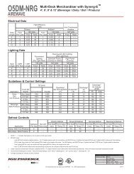
CASE OPERATION<br />
American Style Curved Glass Service Deli/Meat/Seafood Gravity Coil<br />
Merchandiser<br />
OSAG - 4’, 6’, 8’ & <strong>12</strong>’ american style full service, gravity coil<br />
Electrical Data<br />
Model<br />
OSAG<br />
4’<br />
6’<br />
8’<br />
<strong>12</strong>’<br />
Fans per<br />
Case<br />
2<br />
2<br />
3<br />
4<br />
1 NOTE: - - - not an option on this case <strong>model</strong>.<br />
Lighting Data<br />
Model<br />
OSAG<br />
Model<br />
BTUH/ft 2<br />
270<br />
2 BTUHs/ft listed are for parallel operation. Conventional ratings may be approximated by multiplying listed rating by 1.04.<br />
3 Average discharge air velocity at peak of defrost.<br />
4 A suction stop solenoid installed in the top coil’s suction line is required for this case. Control of the solenoid can be achieved with a thermostat at the case or an<br />
external controller. A liquid line solenoid alone will not allow the case to cycle properly and is not recommended for control of this case. The thermostat probe<br />
should be located on the inlet of the top coil. The cut out temperature should be set to 30 o F and the cut in temperature should be set to 35 o F. These are recommended<br />
starting values and may need to be adjusted based on store conditions.<br />
Medium Temperature Defrost Schedule<br />
No. Per Day Hours<br />
1 <strong>12</strong> midnight<br />
2 <strong>12</strong> am - <strong>12</strong> pm<br />
3 6 am - 2 pm - 10 pm<br />
4 <strong>12</strong> - 6 am - <strong>12</strong> - 6 pm<br />
Standard Fans<br />
Amps<br />
0.68<br />
0.68<br />
1.02<br />
1.36<br />
<strong>12</strong>0 Volts<br />
Evaporator<br />
(°F)<br />
15<br />
All measurements are taken per CRMA specifications.<br />
Watts<br />
34<br />
34<br />
51<br />
68<br />
Guidelines & Control Settings<br />
OSAG 4<br />
Model<br />
OSAG<br />
4’<br />
6’<br />
8’<br />
<strong>12</strong>’<br />
Bulbs<br />
per<br />
Row<br />
1<br />
2<br />
2<br />
3<br />
Defrost Controls<br />
Defrosts<br />
Per Day<br />
2<br />
Bulb<br />
Length<br />
4’<br />
3’<br />
4’<br />
4’<br />
Run-Off<br />
Time (min)<br />
6 - 8<br />
Typical per<br />
Light Row<br />
<strong>12</strong>0 Volts<br />
Amps<br />
0.23<br />
0.37<br />
0.47<br />
0.70<br />
High Efficiency<br />
Fans<br />
<strong>12</strong>0 Volts<br />
Amps Watts<br />
0.30 22<br />
0.30 22<br />
0.45 33<br />
0.60 44<br />
Superheat Set<br />
Point @ Bulb ( oF) 6-8<br />
Electric Defrost<br />
Fail-safe<br />
(min)<br />
- - -<br />
Watts<br />
28<br />
44<br />
56<br />
84<br />
Maximum<br />
Lighting<br />
<strong>12</strong>0 Volts<br />
Amps<br />
1.17<br />
1.83<br />
2.33<br />
3.50<br />
Termination<br />
Temp. (°F)<br />
- - -<br />
Watts<br />
140<br />
220<br />
280<br />
420<br />
Discharge Air<br />
(°F)<br />
Anti-Condensate<br />
Heaters<br />
<strong>12</strong>0 Volts<br />
Amps Watts<br />
1.48 178<br />
1.93 232<br />
2.91 349<br />
4.13 496<br />
21-31 38<br />
22<br />
Return Air<br />
(°F)<br />
Timed Off Defrost<br />
Fail-safe<br />
(min)<br />
65<br />
Termination<br />
Temp. (°F)<br />
46<br />
Defrost Heaters<br />
208 Volts<br />
Amps<br />
- - -1 240 Volts<br />
Watts Amps Watts<br />
- - - - - - - - -<br />
- - - - - - - - - - - -<br />
- - - - - - - - - - - -<br />
- - - - - - - - - - - -<br />
Discharge Air Velocity<br />
<strong>12</strong>5<br />
3<br />
(FPM)<br />
Hot Gas Defrost<br />
Fail-safe<br />
(min)<br />
20<br />
Termination<br />
Temp. (°F)<br />
45<br />
Reverse Air Defrost<br />
Fail-safe<br />
(min)<br />
- - -<br />
Termination<br />
Temp. (°F)<br />
- - -
DEFROST AND TEMP CONTROL<br />
These cases are equipped with either<br />
Electric Defrost or Timed-Off Defrost at the<br />
owners option. The sensor bulb and probe for<br />
electric defrost termination and the sensor bulb<br />
for timed off defrost termination are located<br />
behind the front baffle at the location shown in<br />
diagram 1 below. The sensor bulb for temperature<br />
control is located either behind the front<br />
baffle on <strong>model</strong> OSA (diagram 1) or on the inlet<br />
of the top coil on <strong>model</strong> OSAG (diagram 2). The<br />
discharge air probe is located behind the front<br />
baffle of both cases, as shown in diagram 1.<br />
The defrost termination control thermo-<br />
Temperature<br />
Control Bulb<br />
(OSAG)<br />
Coil Outlet<br />
Coil Inlet<br />
2<br />
1<br />
Rear Sill<br />
Thermostat<br />
Location<br />
Ballast<br />
Cover<br />
• Electric defrost termination control sensor bulb location<br />
• Electric defrost termination probe location<br />
• Timed-Off defrost termination probe<br />
• Temperature control sensor bulb location (OSA)<br />
• Discharge air probe location<br />
23<br />
stat and the temperature control thermostat are<br />
located in one of two places depending on the<br />
rear sill. For cases with a standard rear sill the<br />
thermostat is located under the rear sill behind<br />
an easily removable cover, as shown in diagram<br />
3. For cases with a flat rear sill the thermostats<br />
are located in the sliding ballast tray on the bottom,<br />
left front of the case, as shown in diagram<br />
4.<br />
To access the thermostats on cases with<br />
a standard rear sill, simply lift off the ballast<br />
cover from under the rear sill. For cases with a<br />
flat rear sill, access to the thermostats requires<br />
that the rear panel be removed, see illustration<br />
4 below.<br />
It is important to consult the control setting<br />
guidelines shown on pages 21 and 22<br />
before setting defrost times. Further adjustment<br />
may be required depending on store conditions.<br />
3<br />
4<br />
Rear Panel<br />
(Lift Up and<br />
Remove)<br />
Thermostat<br />
Location<br />
Ballast Tray
AIR FLOW AND PRODUCT LOADING<br />
Cases have been designed to provide maximum<br />
product capacity within the refrigerated<br />
air envelope. It is important that you do not<br />
overload the food product display so that it<br />
impinges on the air flow pattern.<br />
Note: Glass hardware is not designed to keep the glass in the<br />
middle position or any other position other than fully opened or<br />
closed<br />
4<br />
2<br />
24<br />
Overloading will cause malfunction and the<br />
loss of proper temperature levels, particularly<br />
when discharge and return air sections are<br />
covered. Please keep products within the load<br />
limit lines shown on the diagram.<br />
3<br />
1<br />
DISCHARGE..............1<br />
LOAD LIMIT...............2<br />
AIR FLOW..................3<br />
RETURN AIR GRILL...4<br />
Caution: When lifting<br />
front glass be sure to<br />
lift from the center<br />
MODEL<br />
OSA & OSAG
CASE CLEANING<br />
USE AND MAINTENANCE<br />
Case is designed to facilitate cleaning. There is a wide<br />
radius formed on the front and back of the inside bottom that<br />
helps accelerate liquid flow and eliminates difficult-to-clean<br />
sharp corners. All surfaces pitch to a deep-drawn drain<br />
trough that angles toward the front and center of case where<br />
the waste outlet is located for easy access.<br />
PLENUM<br />
25<br />
The coil is covered to keep food fluids from entering, but<br />
the cover lifts up easily when coil cleaning is desired. The<br />
fan plenum also lifts up for cleaning, exposing a major portion<br />
of the inside bottom of the tank. Make certain the coil<br />
cover is properly closed after cleaning to avoid air leaks.<br />
Front return air grills snap out for cleaning; no fasteners are<br />
used.<br />
COIL<br />
COVER<br />
DISCHARGE AIR GRILL<br />
(Remove for Cleaning)<br />
FRONT BAFFLE<br />
(Pull Forward)<br />
POSITIVE DRAIN OFF COIL COVER AND PLENUM LIFT UP<br />
CLEAN DISCHARGE AIR GRILL<br />
CLEANING PROCEDURES<br />
• A periodic cleaning schedule should be established to maintain proper sanitation, insure maximum operating efficiency, and<br />
avoid the corrosive action of food fluids on metal parts that are left on for long periods of time. We recommend cleaning once<br />
a week.<br />
• To avoid shock hazard, be sure all electrical power is turned off before cleaning. In some installations, more than one<br />
disconnect switch may have to be turned off to completely de-energize the case.<br />
• Check waste outlet to insure it is not clogged before starting the cleaning process and avoid introducing water faster than the<br />
case drain can carry it away.<br />
• Avoid spraying cleaning solutions directly on fans or electrical connections.<br />
• Avoid using high pressure water to flush the tank. A hose without a nozzle should provide enough pressure for cleaning<br />
purposes. Always use cold water.<br />
COIL<br />
• Allow cases to be turned off long enough to clean any frost or ice from coil and flue areas.<br />
• Remove and clean discharge honeycomb. You may need to use spray detergent and a soft, long bristle brush.<br />
• Use mild detergent and warm water. When necessary, water and baking soda solution will help remove case odors. Avoid<br />
abrasive scouring powders or pads.<br />
• Under no circumstances should abrasive cleaning solutions such as scouring powders or steel wool be used to clean nonglare<br />
glass.<br />
• When cleaning rear door tracks be sure to remove the rear doors and clean from the outside channel to the inside channel<br />
using the wipe-out groove machined into the track.<br />
• Remove front panels and clean underneath the case with a broom and a long handled mop. Instructions for removing the<br />
front panels can be found on page 13 of this manual.<br />
• Use warm water and a disinfecting cleaning solution when cleaning underneath the cases.<br />
• Note: Glass hardware is not designed to keep the glass in the middle position or any other position other than fully opened or<br />
closed.
GLASS CLEANING<br />
SOVIS ULTRAVISION® tempered glass has specialized Anti-<br />
Reflective coatings on each surface of the glass. These coatings<br />
reduce the glare from lighting so that the products on<br />
display are more visible to your customers.<br />
While the Anti-Reflective coatings are durable, they are susceptible<br />
to scratching if abrasive materials are used for cleaning. Once the glass surfaces are<br />
scratched, it is impossible to restore the original finish. Special care must be taken to prevent damage<br />
when cleaning the glass. SOVIS recommends the following products for routine cleaning of<br />
ULTRAVISION® Anti-Reflective glass:<br />
Cleaning Cloths - two products are recommended…<br />
• Scotch-Brite® High Performance Cloth - manufactured by 3M® and available in most grocery<br />
stores under the name Scotch-Brite® Microfiber Cleaning Cloth in a <strong>12</strong>" x 14" size. This cloth is<br />
washable and may be reused as long as it remains clean.<br />
• Spontex® Microfibre Cleaning Cloth - distributed by Spontex® and available in most grocery stores<br />
under the same name in a 15.75" x <strong>12</strong>" size. This cloth is washable and may be reused as long as it<br />
remains clean.<br />
Cleaning Fluid - for more difficult cleaning jobs, these products are recommended…<br />
• Windex® - standard product only (extra-strength or specialty products may not be suitable)<br />
• Glass-Plus® - standard product only (extra-strength or specialty products may not be suitable)<br />
• Warm Water<br />
Note: equivalent store-brand glass cleaning products are normally acceptable substitutes to the<br />
brand name products listed above.<br />
The cleaning cloths named above will normally remove dust, grease, oil, and fingerprints without the<br />
need for cleaning fluids. A light spray of the cleaning fluids listed above will reduce the time required<br />
for cleaning. These materials have been tested and proven to clean ULTRAVISION® glass without<br />
scratching or damaging the Anti-Reflective coatings. If you need assistance with obtaining these<br />
materials, please contact your display case supplier.<br />
Under no circumstances should the following types of materials be used for cleaning glass with<br />
ULTRAVISION® Anti-Reflective coatings.<br />
• Coarse Paper Towels<br />
• Scouring Pads or Powders<br />
• Steel Wool or Steel Fiber Materials<br />
• Blades<br />
• Acidic or highly Alkaline detergents<br />
• Fluorine based detergents<br />
26<br />
WARNING!<br />
DO NOT USE THESE MATERIALS
RECOMMENDATIONS FOR CLEANING ULTRAVISION GLASS<br />
ULTRAVISION glass is more sensitive to scratches than regular float glass. Therefore, it is important<br />
to carefully follow the recommendations listed below regarding the materials and chemicals<br />
that may be used:<br />
Regular Cleaning<br />
· Soft rags with water and soft detergent<br />
· Chamois leather with water and soft detergent<br />
· Soft sponge with water and soft detergent<br />
· Rubber wiper with water and soft detergent<br />
· A neutral chemical can also be used (WINDEX, GLASS PLUS, etc.)<br />
For More Difficult Cleaning<br />
· Acetone<br />
· Trichlorethylene<br />
· Methlyated spirits<br />
· Petroleum ether<br />
· White spirit<br />
Never Use<br />
· Acids<br />
· High alkaline detergents<br />
· Fluorine based detergents<br />
· Scouring powders<br />
· Scouring pads<br />
· Blades<br />
· Steel wool<br />
· Steel fiber materials<br />
Note that the intrinsic structure of anti-glare coatings makes the surface roughness of<br />
ULTRAVISION glass rather high. However, after a few cleanings, the surface of the glass is<br />
smoother, and is therefore easier to clean.<br />
27
USE AND MAINTENANCE<br />
FANS<br />
The evaporator fans are equipped with 5 watt<br />
fan motors, 1550 RPM’s. The motor has a counter<br />
clockwise rotation when viewed from the shaft end.<br />
The fan blades are 6” in diameter and the blades are<br />
pitched according to the charts below. It is important<br />
that the blade pitch be maintained as specified.<br />
Do not attempt a field modification by altering<br />
the blades.<br />
Fan motors may be changed with an easy twostep<br />
process without lifting up the plenum, thereby<br />
avoiding the necessity to unload the entire product<br />
display to make a change:<br />
1. Unplug the fan motor, easily accessible out<br />
side the plenum<br />
2. Remove three fasteners, then lift out the<br />
entire fan basket<br />
MODEL<br />
OSA-4’, OSA-6’<br />
OSAG-4’, OSAG-6’<br />
MODEL<br />
OSA-8’<br />
OSAG-8’<br />
28<br />
1<br />
Model OSA<br />
6’<br />
No.<br />
Fans<br />
2<br />
Blade<br />
Pitch<br />
37 o<br />
4’<br />
2<br />
37 o<br />
8’<br />
3<br />
MODEL<br />
OSA-<strong>12</strong>’<br />
OSAG-<strong>12</strong>’<br />
37 o<br />
Model OSAG<br />
6’<br />
No.<br />
Fans<br />
2<br />
Blade<br />
Pitch<br />
15 o<br />
4’<br />
2<br />
15 o<br />
8’<br />
3<br />
15 o<br />
2<br />
<strong>12</strong>’<br />
4<br />
37 o<br />
<strong>12</strong>’<br />
4<br />
15 o
Procedure<br />
PARTS ORDERING<br />
1. Contact the Service Parts Department<br />
<strong>Hill</strong> PHOENIX<br />
1925 Ruffin Mill Road<br />
Colonial Heights, Virginia 23834<br />
Tel: 800-283-1109<br />
Fax: 804-526-3897<br />
2. Provide the following information about the part you are ordering:<br />
• Model number and serial number of the case on which<br />
the part is used.<br />
• Length of part, if applicable, I.E. 4’, 6’, 8’, <strong>12</strong>’.<br />
• Color of part if painted, or color of polymer part.<br />
• Whether part is for left hand or right hand application.<br />
• Whether shelves are with or without lights.<br />
• Quantity<br />
*Serial plate is located on rear panel on the right hand side of<br />
the case (See illustrations on pages 4 thru 7).<br />
3. If parts are to be returned for credit, ask the Parts Department to<br />
furnish you with a Return Materials Authorization Number.<br />
29
PARTS ORDERING<br />
48 36 53 9a 20 46 56 55<br />
E09<br />
E20<br />
49<br />
23<br />
E11<br />
E10<br />
E01<br />
69<br />
E11<br />
77<br />
E10<br />
E09<br />
30<br />
21<br />
11<br />
28<br />
24<br />
69<br />
70<br />
29<br />
66<br />
42<br />
5<br />
1<br />
9<br />
50<br />
E06<br />
3<br />
26<br />
17<br />
22<br />
2<br />
MODEL<br />
OSA & OSAG<br />
82<br />
81<br />
87<br />
E07<br />
88
Location Part Descriptions<br />
Number<br />
1 Kickplate, Storm Grey<br />
2 Master Bumper, Featherstone, Smoke, White, French Vanilla, Black<br />
3 Lower Front Panel, Painted or Stainless<br />
5 Front Glass, Lift-Up Thermopane<br />
9 Deck Pan, Painted, Unpainted, Stainless<br />
9a Plenum Cover<br />
11 Front Baffle, Aluminum, Painted White, Custom Color, or Stainless<br />
17 Nose Bumper, Custom Color<br />
20 Lower Rear Baffle, Painted White, Custom Color, or Stainless<br />
21 Shelf Standard, Specify standard or Vieler Shelving<br />
22 Shelves, Lighted or Unlighted, Painted White, Custom Color or Stainless<br />
23 Electrical Junction Box, or Sliding Ballast Tray<br />
24 “J” Rail, for Kickplate<br />
25 Top Flue Panel, Painted Custom Color or Stainless (Not Shown)<br />
26 Front Panel, Painted Custom Color, or Stainless<br />
28 Discharge Air Grill<br />
29 Lightrod,<br />
36 Plug Button<br />
42 Glass Pressure Bar<br />
46 Glass Clamp<br />
48 Rear Sill, Stainless Steel<br />
49 Rear Filler Panel<br />
50 Lamp Shield<br />
53 Mullion Cover, Stainless Steel<br />
54 Inside Mullion Cover, (Not Shown)<br />
55 Doors, Specify Outside or Inside when ordering<br />
56 Door Frame<br />
62 Light Rod Cover (Not Shown)<br />
66 Front Extensions, Inside and Outside<br />
69 Coil, Specify upper or lower coil<br />
70 Coil Louvers<br />
77 P-Trap<br />
81 Wire Racks<br />
82 Tag Moulding<br />
83 Thermometer, and Bracket (Not Shown)<br />
87 End Assembly, Solid, Full view, Custom Color<br />
Identify, Left or Right hand, Color of Panel, and color of PVC End Trim<br />
88 End Kickplate, Storm Grey<br />
E01 Defrost Heaters<br />
E02 Anti-Condensate Heaters, (Not Shown)<br />
E03 Thermostats, Temperature and Defrost Termination Control, (Not Shown)<br />
E05 Light Switch, (Not Shown)<br />
E06 Lamp Holder<br />
E07 Bulb<br />
E08 Ballast, Electronic, (Not Shown), (Identify by brand name and <strong>model</strong> number)<br />
E09 Fan Motor - State High Efficiency or Standard<br />
E10 Fan Blade 6”<br />
E11 Fan Basket, 6”<br />
E19 Receptacle, Recessed, Shelf Light Outlet, White (Not Shown)<br />
E20 Fan Cord-Set - High Efficiency or Standard (Not Shown)<br />
Note: Ballasts are located under the rear sill for cases equipped with a standard rear sill . Cases equipped with a flat<br />
rear sill have the ballasts located in a sliding ballast tray underneath the case.<br />
31
NOTES<br />
32
NOTES<br />
34
WARRANTY<br />
HEREINAFTER REFERRED TO AS MANUFACTURER<br />
FOURTEEN MONTH WARRANTY. MANUFACTURER’S PRODUCT IS WARRANTED TO BE FREE FROM<br />
DEFECTS IN MATERIAL AND WORKMANSHIP UNDER NORMAL USE AND MAINTENANCE FOR A<br />
PERIOD OF FOURTEEN MONTHS FROM THE DATE OF ORIGINAL SHIPMENT. A NEW OR REBUILT<br />
PART TO REPLACE ANY DEFECTIVE PART WILL BE PROVIDED WITHOUT CHARGE, PROVIDED THE<br />
DEFECTIVE PART IS RETURNED TO MANUFACTURER. THE REPLACEMENT PART ASSUMES THE<br />
UNUSED PORTION OF THE WARRANTY.<br />
This warranty does not include labor or other costs incurred for repairing, removing, installing, shipping, servicing,<br />
or handling of either defective parts or replacement parts.<br />
The fourteen month warranty shall not apply:<br />
1. To any unit or any part thereof which has been subject to accident, alteration, negligence, misuse or<br />
abuse, operation on improper voltage, or which has not been operated in accordance with the<br />
manufacturer’s recommendation, or if the serial number of the unit has been altered, defaced, or removed.<br />
2. When the unit, or any part thereof, is damaged by fire, flood, or other act of God.<br />
3. Outside the continental United States.<br />
4. To labor cost for replacement of parts, or for freight, shipping expenses, sales tax or upgrading.<br />
5. When the operation is impaired due to improper installation.<br />
6. When installation and startup forms are not properly complete or returned within two weeks after startup.<br />
THIS PLAN DOES NOT COVER CONSEQUENTIAL DAMAGES. Manufacturer shall not be liable under any circumstances<br />
for any consequential damages, including loss of profit, additional labor cost, loss of refrigerant<br />
or food products, or injury to personnel or property caused by defective material or parts or for any delay<br />
in its performance hereunder due to causes beyond its control. The foregoing shall constitute the sole and<br />
exclusive remedy of any purchases and the sole and exclusive liability of Manufacturer in connection with<br />
this product.<br />
The Warranties are Expressly in Lieu of All Other Warranties, Express of Implied and All Other Obligations<br />
or Liabilities on Our Part. The Obligation to Repair or Replace Parts or Components Judged to be<br />
Defective in Material or Workmanship States Our Entire Liability Whether Based on Tort, Contract or<br />
Warranty. We Neither Assume Nor Authorize Any Other Person to Assume for Us Any Other Liability in<br />
Connection with Our Product.<br />
MAIL CLAIM TO:<br />
<strong>Hill</strong> PHOENIX<br />
Display Merchandisers<br />
1925 Ruffin Mill Road<br />
Colonial Heights, VA 23834<br />
804-526-4455<br />
<strong>Hill</strong> PHOENIX<br />
Refrigeration Systems &<br />
Electrical Distribution Products<br />
709 Sigman Road<br />
Conyers, GA 30013<br />
770-285-3200<br />
05/09a
BDM0519<br />
804-526-4455<br />
Warning<br />
Maintenance & Case Care<br />
When cleaning cases the following must be performed<br />
PRIOR to cleaning:<br />
To avoid electrical shock, be sure all electric power is turned<br />
off before cleaning. In some installations, more than one<br />
switch may have to be turned off to completely de-energize<br />
the case.<br />
Do not spray cleaning solution or water directly on fan<br />
motors or any electrical connections.<br />
All lighting receptacles must be dried off prior to insertion<br />
and re-energizing the lighting circuit.<br />
Please refer to the Use and Maintenance section of this installation manual.<br />
1925 Ruffin Mill Road, Colonial Heights, VA 23834<br />
Due to our commitment to continuous improvement all specifications are subject to change without notice.<br />
<strong>Hill</strong> PHOENIX is a Sustaining Member of the American Society of Quality<br />
Visit our web site at www.hillphoenix.com