


You also want an ePaper? Increase the reach of your titles
YUMPU automatically turns print PDFs into web optimized ePapers that Google loves.
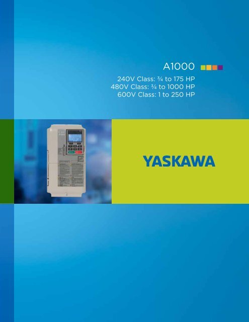
<strong>A1000</strong><br />
240V Class: ¾ to 175 HP<br />
480V Class: ¾ to 1000 HP<br />
600V Class: 1 to 250 HP
A Single Drive for all Your Needs,<br />
with Outstanding Performance and Flexibility!<br />
The <strong>A1000</strong> is a full-featured drive, providing outstanding quality, performance, flexibility,<br />
and environmental friendliness through 1000HP. From simple fans and pumps to complex<br />
machine control, <strong>A1000</strong> can be the single drive platform for an entire facility. Network<br />
communications, expandable I/O, and feedback are among the many choices. For new<br />
installations or retrofits, the <strong>A1000</strong> provides a single robust solution, regardless of your<br />
application.<br />
<strong>Yaskawa</strong> <strong>A1000</strong><br />
Family of <strong>AC</strong> <strong>Drives</strong><br />
Configured <strong>A1000</strong><br />
Drive Package<br />
Standard <strong>A1000</strong> <strong>Drives</strong><br />
2
Contents<br />
Features, Benefits and Specifications 4<br />
Drive and Accessories Selection 16<br />
Mechanical Installation Planning 41<br />
Electrical Installation Planning 46<br />
<strong>A1000</strong> Configured Package 50<br />
<strong>Yaskawa</strong> Industrial <strong>Drives</strong> Family 52<br />
Global Service Network 54<br />
RoHS<br />
compliant<br />
3<br />
3
Features and Benefits<br />
Exceptional Quality<br />
Enjoy peace of mind by knowing that you are considering a product from <strong>Yaskawa</strong>, the factory automation<br />
controls company with the highest reputation for quality and reliability. Historically, <strong>Yaskawa</strong> drives have<br />
demonstrated extremely high reliability with an average MTBF (mean time between failure) of 28 years or<br />
more. The new 1000 series products take reliability to the next level with a calculated design life that is<br />
twice as long as previous generations.<br />
Highly Integrated Design results in fewer parts and<br />
interconnections, reducing the number of failure points.<br />
Component Derating extends the life of any single part<br />
by selecting higher specifications (e.g. voltage, current)<br />
than what a circuit requires for normal operation.<br />
Latest Generation IGBT Power Modules, capable of<br />
four times more thermal cycles than previous designs.<br />
Enhanced Short Circuit Detection and Self<br />
Diagnostics provide additional protection against<br />
severe catastrophic conditions.<br />
In addition, the <strong>A1000</strong> is designed for use around the world, and carries agency certifications for all<br />
major geographical regions<br />
4
Easy to Apply and Maintain<br />
Whether your applications are simple or complex, the <strong>A1000</strong> is supported by user-friendly configuration<br />
tools. For local field access, the keypad interface features a multi-language LCD display, parameter storage,<br />
and application presets to make programming a simple task. It also has built-in memory for backup<br />
purposes. In addition, a USB Copy Unit can be loaded with a drive’s program for convenient portable<br />
transfer of configuration between an office environment and the factory floor.<br />
HV<strong>AC</strong><br />
Compressor<br />
Setting<br />
00<br />
01<br />
02<br />
03<br />
04<br />
05<br />
Application<br />
General-purpose<br />
Water Supply Pump<br />
Conveyor<br />
Exhaust Fan<br />
HV<strong>AC</strong> Fan<br />
Air Compressor<br />
Fan<br />
Conveyor<br />
Pump<br />
Extruders<br />
Parameters are programmed automatically<br />
A1-02 Control mode selection<br />
C1-01 Accel Time 1<br />
C1-02 Decel Time<br />
C6-01 ND/HD Selection<br />
Features, Benefits and Specifications<br />
DriveWizard® computer software delivers configuration, monitoring, and trending functions enhanced<br />
by direct connectivity through the <strong>A1000</strong>’s standard USB port.<br />
• Online and Offline Editing<br />
• Application Wizard<br />
• Monitoring and Diagnostic Panels<br />
• Trend Recorder and Playback<br />
• Network Configurator<br />
• Multidrive Support<br />
• Drive Flash Support<br />
• Project Converter<br />
• Report and Export Generation<br />
• Search Engine<br />
5
Features and Benefits<br />
Easy to Apply and Maintain<br />
Preventative Maintenance Monitors<br />
Maximize production and intelligently schedule your maintenance<br />
by making use of the <strong>A1000</strong>’s special monitors that provide alarm<br />
information when a drive requires attention. Use this information<br />
to trigger discrete outputs or send the status across a network for<br />
upper level decision making.<br />
• Cooling Fan Remaining Life<br />
• IGBT (Power Module) Remaining Life<br />
• Bus Capacitor Remaining Life<br />
• Precharge Relay<br />
• Drive (Heatsink) Temperature<br />
Highly Reliable and Easily Replaceable<br />
Cooling Fans<br />
• Improved location for convenient access<br />
• No tools required<br />
• 24Vdc powered (including large<br />
ratings) eliminates need to make proper<br />
connection at time of installation<br />
Removeable I/O Terminal Board with Drive<br />
Backup Memory<br />
• All parameter changes automatically saved to both<br />
main control board and I/O board<br />
• Leave I/O connected when replacing a drive<br />
• Configuration is downloaded to replacement drive<br />
• Reduces MTTR (Mean Time To Repair)<br />
6
Maximum Flexibility<br />
Have it your way with the <strong>A1000</strong>’s impressive flexibility. Take advantage of a significant quantity of<br />
control points as standard. For applications requiring more I/O, feedback, or network choices, the<br />
<strong>A1000</strong> offers three expansion ports that support a a wide variety of interface modules.<br />
Standard I/O and Communications<br />
• Digital Inputs (8)<br />
• Analog Inputs (3)<br />
• Pulse Inputs (1)<br />
• Digital Outputs (4)<br />
• Analog Outputs (2)<br />
• Pulse Outputs (1)<br />
• RS485 Modbus RTU Communication<br />
Features, Benefits and Specifications<br />
Expansion Capability<br />
I/O Modules<br />
• Digital Inputs (16)<br />
• Analog Inputs (3)<br />
• Digital Outputs (8)<br />
• Analog Outputs (2)<br />
Feedback Modules<br />
• Incremental Encoder<br />
• Resolver<br />
• Absolute Encoder (Stegmann, Heidenhain)<br />
Communication Modules<br />
• DeviceNet<br />
• EtherNet/IP<br />
• Modbus TCP/IP<br />
• PROFIBUS-DP<br />
• PROFINET<br />
• MECHATROLINK-II<br />
• EtherCAT<br />
• Metasys N2/Apogee FLN (P1)<br />
• B<strong>AC</strong>net<br />
• LonWorks<br />
7
Features and Benefits<br />
Maximum Flexibility<br />
Auxiliary Control Power Input<br />
Keep your drives communicating over the network, even<br />
while main power is removed. The Auxiliary Control Power<br />
Input uses facility supplied 24Vdc to keep the drive’s control<br />
and communication intact. Service your drive cabinets with<br />
the benefit of live control and communications without the<br />
need for main power and associated Arc Flash protection.<br />
Embedded Functional Safety<br />
Minimize downtime for applications<br />
requiring occasional or frequent mechanical<br />
intervention. Safe Torque Off provides<br />
<strong>A1000</strong><br />
Power<br />
Supply<br />
safe removal of torque without removal of<br />
power to the drive. The <strong>A1000</strong> provides this<br />
functionality as standard in a safety category<br />
3 architecture, and is certified by TUV to PLd<br />
Safety<br />
controller<br />
Feedback loop<br />
HC<br />
H1<br />
H2<br />
Controller<br />
and SIL CL2 according to ISO/EN 13849-1<br />
EDM<br />
DM+<br />
and IEC/EN 62061 respectively, meeting the<br />
DM−<br />
requirements of IEC/EN 61508.<br />
Motor<br />
Space Saving Features<br />
The <strong>A1000</strong> offers world class power density resulting in an average size reduction of 30% as compared to<br />
previous generations (see individual rating dimensions). In addition, even more cabinet space can be saved by<br />
taking advantage of External Heatsink Mounting or its Zero Side Clearance capability.<br />
Physical Size Reduction<br />
External Heatsink Solution<br />
(Side View)<br />
Zero Side Clearance<br />
(40°C max ambient)<br />
8
Maximum Flexibility<br />
A variety of braking solutions optimized for your application.<br />
• For high demand braking conditions,<br />
the <strong>A1000</strong> provides powerful Dynamic<br />
Braking with integrated brake transistors<br />
through 50HP normal duty (40HP heavy<br />
duty). For drives rated through 7.5HP<br />
normal duty (5HP heavy duty), drive<br />
mounted low duty cycle resistors are<br />
available<br />
• For applications that can dissipate losses<br />
in the motor, Over-Excitation Braking and<br />
High Slip Braking are good performing,<br />
money saving alternatives to dynamic<br />
braking<br />
Power<br />
supply<br />
voltage<br />
Motor<br />
speed<br />
Motor decelerates quickly to<br />
protect the application<br />
Controlled ramp to stop<br />
• In the event of a power loss, Kinetic Energy<br />
Braking uses energy stored in the rotating<br />
load to keep the drive powered and bring the<br />
process to a controlled stop<br />
Features, Benefits and Specifications<br />
Keep your applications running with features designed to avoid interruptions that are typical with<br />
demanding load conditions.<br />
• Optimal Decel automatically extends the<br />
programmed deceleration time based on<br />
the load condition and drive capability<br />
• Overvoltage Suppression limits the<br />
DC bus voltage by modulating output<br />
frequency to keep the drive out of the<br />
regenerative region<br />
Power supply<br />
voltage<br />
Motor speed<br />
Output frequency<br />
1750 r/min<br />
• Overload Fault Prevention responds<br />
to heavy load conditions by adjusting<br />
output frequency and voltage to keep the<br />
drive’s current within operating limits<br />
Output current<br />
Uses regenerative energy to<br />
keep the application running<br />
• Momentary Power Loss Ride-Thru<br />
puts the drive in standby mode<br />
during transient power losses and<br />
then automatically restarts, avoiding<br />
potentially costly power related shut<br />
down conditions<br />
• Speed Search allows the drive to start into a<br />
rotating load by quickly matching its speed before<br />
delivering full power<br />
Note: Separate sensor to detect power loss is required.<br />
maintain operation, the drive will coast to rest.<br />
9
Features and Benefits<br />
Maximum Flexibility<br />
• Embedded Application Functions provide system level control without the use of a stand-alone controller.<br />
• PID (Proportional Integral Derivative) Control regulates your process variable (flow, pressure, etc,).<br />
• Droop Control automatically adjusts motor slip to perform load sharing in a multi-drive system.<br />
• Function Block Programming supported by DriveWorksEZ® offers internal logic functions to build the<br />
application of your choice.<br />
• Drag and Drop Graphical Environment<br />
• Interface with I/O, Drive Data, Network Data<br />
• Logic Functions<br />
• Math Functions<br />
• Timers<br />
• Counters<br />
• Subroutine Creation<br />
• Up to 289 Function Blocks<br />
• Up to 100 Connections<br />
• 1 millisecond execution<br />
A single drive to control traditional and emerging motor technologies:<br />
• Induction Motors<br />
• Low cost<br />
• Widely available<br />
• Efficient<br />
• Interior Permanent Magnet (IPM) Motors<br />
• Very Compact<br />
• Highly Efficient<br />
• Sensorless High Precision Control<br />
• Surface Permanent Magnet (SPM) Motors<br />
• Ultra Compact<br />
• Highly Efficient<br />
Induction<br />
Motors<br />
Surface<br />
Permanent<br />
Magnet<br />
(SPM) Motors<br />
Interior<br />
Permanent<br />
Magnet<br />
(IPM) Motors<br />
Type 12 Flange Configuration<br />
<strong>A1000</strong> is available in all ratings as a Type 12 Flange configuration<br />
that allows for mounting the drive with its heatsink out the back<br />
of any Type 12 enclosure. This allows for the majority of the<br />
drive’s heat to dissipate on the external side, while keeping the<br />
enclosure small and sealed with Type 12 integrity.<br />
10
Outstanding Performance<br />
The <strong>A1000</strong> delivers incredible performance, producing up to 200% torque with or without feedback.<br />
• Continuous Autotuning automatically<br />
compensates for changes in motor<br />
temperature<br />
• Inertia Autotuning automatically sets<br />
gains for speed and torque loops<br />
• Dead-Time Compensation drastically<br />
reduces torque ripple at low speeds<br />
• High Frequency Injection (for IPM<br />
motors) enables high precision<br />
control without feedback, including<br />
positioning to within ± 5 degrees !<br />
Previous<br />
Generation<br />
<strong>A1000</strong><br />
Torque Ripple (0.5% / div)<br />
Speed<br />
Control<br />
Range<br />
Speed<br />
Accuracy<br />
Speed<br />
Response<br />
Torque<br />
Response<br />
1500:1 Closed Loop Vector (Inducon and PM Motors)<br />
200:1 Open Loop Vector (Inducon Motors)<br />
100:1 Open Loop Vector (IPM Motors)<br />
0.02% -Closed Loop Vector (Inducon Motors)<br />
0.2% - Open Loop Vector (Inducon Motors)<br />
0.00% - Closed Loop Vector (IPM & SPM Motors)<br />
0.00% -Open Loop Vector (IPM Motors)<br />
60 Hz -Closed Loop Vector<br />
10 Hz -Open Loop Vector<br />
300 Hz - Closed Loop Vector<br />
Features, Benefits and Specifications<br />
Environmentally Friendly<br />
Reduce your energy bill and contribute towards a cleaner environment with sustainable features designed<br />
into the <strong>A1000</strong>.<br />
Built-in DC Reactors (30<br />
HP and larger) provide<br />
input harmonics benefit,<br />
and protection from input<br />
disturbances.<br />
To further reduce harmonics<br />
reflected back to the utility<br />
power line, the <strong>A1000</strong> is<br />
available with an integrated<br />
12-pulse diode bridge from<br />
40 to 1000 HP @ 480 V<strong>AC</strong><br />
(also requires the use of<br />
an external phase shifting<br />
transformer<br />
Without Reactor (88% THD)<br />
With Reactor (40% THD)<br />
12 Pulse Drive<br />
(Less than 15% THD)<br />
Applying variable speed often<br />
results in large energy savings.<br />
Combining this with more<br />
efficient motors magnifies the<br />
result.<br />
All materials used in the<br />
<strong>A1000</strong> comply with the<br />
directive for Restriction<br />
of Hazardous Substances<br />
(RoHS)<br />
11
Specifications<br />
240V Class<br />
Model CIMR-AU2A 0004 0006 0008 0010 0012 0018 0021 0030 0040 0056<br />
Max. Applicable<br />
Normal Duty 0.75 1.5 2 3 3 5 7.5 10 15 20<br />
Motor Capacity *1 <br />
HP Heavy Duty 0.75 1 2 2 3 3 5 7.5 10 15<br />
Rated Input Current *2 A<br />
Normal Duty 3.9 7.3 8.8 10.8 13.9 18.5 24 37 52 68<br />
Heavy Duty 2.9 5.8 7 7.5 11 15.6 18.9 28 37 52<br />
Rated Output Capacity *4 kVA Normal Duty*5 1.3 2.3 3 3.7 4.6 6.7 8 11.4 15.2 21<br />
Heavy Duty 1.2 *6 1.9 *6 2.6 *6 3 *6 4.2 *6 5.3 *6 6.7 *6 9.5 *5 12.6 *5 17.9 *5<br />
Input<br />
Output<br />
Power<br />
Rated Output Current A Normal Duty*5 3.5 6 8 9.6 12 17.5 21 30 40 56<br />
Heavy Duty 3.2 *6 5 *6 6.9 *6 8 *6 11 *6 14 *6 17.5 *6 25 *5 33 *5 47 *5<br />
Normal Duty Rating: 120% of rated output current for 60 sec.<br />
Overload Tolerance<br />
Heavy Duty Rating: 150% of rated output current for 60 sec.<br />
(Derating may be required for applications that start and stop frequently)<br />
Carrier Frequency (User Adjustable)<br />
2 to 15 kHz<br />
Max. Output Voltage<br />
Three-phase 200 to 240 V (relative to input voltage)<br />
Max. Output Frequency<br />
400 Hz<br />
Rated Voltage/Rated Frequency Three-phase 200 to 240 Vac 50/60 Hz 270 to 340 Vdc *3<br />
Allowable Voltage Fluctuation -15% to +10%<br />
Allowable Frequency Fluctuation ±5%<br />
Braking Transistor<br />
Included<br />
Fan No fan With fan<br />
DC Link Choke<br />
External Option<br />
Power Supply kVA<br />
Normal Duty 2.2 3.1 4.1 5.8 7.8 9.5 14 18 27 36<br />
Heavy Duty 1.3 2.2 3.1 4.1 5.8 7.8 9.5 14 18 27<br />
Model CIMR-AU2A 0069 0081 0110 0138 0169 0211 0250 0312 0360 0415<br />
Max. Applicable<br />
Normal Duty 25 30 40 50 60 75 100 125 150 175<br />
Motor Capacity *1 <br />
HP Heavy Duty 20 25 30 40 50 60 75 100 125 150<br />
Rated Input Current *2 A<br />
Normal Duty 80 96 111 136 164 200 271 324 394 471<br />
Heavy Duty 68 80 82 111 136 164 200 271 324 394<br />
Rated Output Capacity *4 kVA Normal Duty*5 26 31 42 53 64 80 95 119 137 158<br />
Heavy Duty 23 *6 29 *6 32 *6 44 *6 55 *6 69 *7 82 *7 108 *7 132 *7 158 *5<br />
Input<br />
Output<br />
Power<br />
Rated Output Current A Normal Duty*5 69 81 110 138 169 211 250 312 360 415<br />
Heavy Duty 60 *6 75 *6 85 *5 115 *6 145 *6 180 *7 215 *7 283 *7 346 *7 415 *5<br />
Normal Duty Rating: 120% of rated output current for 60 sec.<br />
Overload Tolerance<br />
Heavy Duty Rating: 150% of rated output current for 60 sec.<br />
(Derating may be required for applications that start and stop frequently)<br />
Carrier Frequency (User Adjustable) 2 to 15 kHz 2 to 10 kHz<br />
Max. Output Voltage<br />
Three-phase 200 to 240 V (relative to input voltage)<br />
Max. Output Frequency<br />
400 Hz (user-set)<br />
Rated Voltage/Rated Frequency Three-phase 200 to 240 Vac 50/60 Hz 270 to 340 Vdc *3<br />
Allowable Voltage Fluctuation -15% to +10%<br />
Allowable Frequency Fluctuation ±5%<br />
Braking Transistor Included External Option<br />
Fan<br />
With fan<br />
DC Link Choke External Option Included<br />
Power Supply kVA<br />
Normal Duty 44 52 51 62 75 91 124 148 180 215<br />
Heavy Duty 36 44 37 51 62 75 91 124 148 180<br />
*1. The motor capacity (HP) refers to a NEC rated 4-pole motor. The rated output current of the drive output amps should be equal to or greater than the<br />
motor current. Select the appropriate capacity drive if operating the motor continuously above motor nameplate current.<br />
*2. Assumes operation at the rated output current. Input current rating varies depending on the power supply transformer, input reactor, wiring<br />
connections, and power supply impedance.<br />
*3. DC is not available for UL/CE standards.<br />
*4. Rated motor capacity is calculated with a rated output voltage of 230V.<br />
*5. Carrier frequency is set to 2 kHz. Current derating is required in order to raise the carrier frequency.<br />
*6. Carrier frequency can be increased to 8 kHz while keeping this current derating. Higher carrier frequency settings require derating.<br />
*7. Carrier frequency can be increased to 5 kHz while keeping this current derating. Higher carrier frequency settings require derating.<br />
12
480V Class<br />
Model CIMR-AU4A 0002 0004 0005 0007 0009 0011 0018 0023 0031 0038 0044 0058 0072<br />
Max. Applicable Normal Duty 1 2 3 3 5 7.5 10 15 20 25 30 40 50<br />
Motor Capacity *1 HP Heavy Duty 0.75 2 3 3 5 5 10 10 15 20 30 30 40<br />
Power<br />
Output<br />
Input<br />
Rated Input Normal Duty 2.1 4.3 5.9 8.1 9.4 14 20 24 38 51 60 58 71<br />
Current *2 A Heavy Duty 1.8 3.2 4.4 6 8.2 10.4 15 20 29 41 51 43 58<br />
Rated Output Normal Duty *5 1.6 3.1 4.1 5.3 6.7 8.5 13.3 17.5 24 29 34 44 55<br />
Capacity *4 kVA Heavy Duty 1.4 *6 2.6 *6 3.7 *6 4.2 *6 5.5 *6 7 *6 11.3 *6 13.7 *6 18.3 *6 24 *6 30 *6 34 *6 48 *6<br />
Rated Output Normal Duty *5 2.1 4.1 5.4 6.9 8.8 11.1 17.5 23 31 38 44 58 72<br />
Current A Heavy Duty 1.8 *6 3.4 *6 4.8 *6 5.5 *6 7.2 *6 9.2 *6 14.8 *6 18 *6 24 *6 31 *6 39 *6 45 *6 60 *6<br />
Normal Duty Rating: 120% of rated output current for 60 sec.<br />
Overload Tolerance<br />
Heavy Duty Rating: 150% of rated output current for 60 sec.<br />
(Derating may be required for repetitive loads)<br />
Carrier Frequency (User Adjustable)<br />
2 to 15 kHz<br />
Max. Output Voltage<br />
Three-phase 380 to 480 V (relative to input voltage)<br />
Max. Output Frequency<br />
400 Hz<br />
Rated Voltage/Rated Frequency Three-phase 380 to 480 Vac 50/60 Hz 510 to 680 Vdc *3<br />
Allowable Voltage Fluctuation -15% to +10%<br />
Allowable Frequency Fluctuation ±5%<br />
Braking Transistor<br />
Included<br />
Fan No fan With fan<br />
DC Link Choke External Option Included<br />
Normal Duty 2.3 4.3 6.1 8.1 10 14.5 19.4 28.4 37.5 46.6 54.9 53 64.9<br />
Power Supply kVA<br />
Heavy Duty 1.4 2.3 4.3 6.1 8.1 10 14.6 19.2 28.4 37.5 46.6 39.3 53<br />
Features, Benefits and Specifications<br />
Model CIMR-AU4A 0088 0103 0139 0165 0208 0250 0296 0362 0414 0515 0675 0930 1200<br />
Max. Applicable Normal Duty 60 75 100 125 150 200 250 300 350 450 600 800 1000<br />
Motor Capacity *1 HP Heavy Duty 60 60 75 100 150 150 200 250 300 350 500 700 900<br />
Rated Input Normal Duty 86 105 142 170 207 248 300 346 410 465 657 922 1158<br />
Current *2 A Heavy Duty 71 86 105 142 170 207 248 300 346 410 584 830 1031<br />
Rated Output Normal Duty *5 67 78 106 126 159 191 226 276 316 392 514 709 915<br />
Capacity *4 kVA Heavy Duty 57 *6 69 *6 85 *6 114 *7 137 *7 165 *7 198 *7 232 *7 282 *5 343 *5 461 *5 617 *5 831 *5<br />
Rated Output Normal Duty *5 88 103 139 165 208 250 296 362 414 515 675 930 1200<br />
Current A Heavy Duty 75 *6 91 *6 112 *6 150 *7 180 *7 216 *7 260 *7 304 *7 370 *5 450 *5 605 *5 810 *5 1090 *5<br />
Normal Duty Rating: 120% of rated output current for 60 sec.<br />
Overload Tolerance<br />
Heavy Duty Rating: 150% of rated output current for 60 sec.<br />
(Derating may be required for repetitive loads)<br />
Carrier Frequency (User Adjustable) 2 to 15 kHz 2 to 10 kHz 2 to 5 kHz<br />
Max. Output Voltage<br />
Three-phase 380 to 480 V (relative to input voltage)<br />
Max. Output Frequency<br />
400 Hz (user-set)<br />
Rated Voltage/Rated Frequency Three-phase 380 to 480 Vac 50/60 Hz 510 to 680 Vdc *3<br />
Allowable Voltage Fluctuation -15% to +10%<br />
Allowable Frequency Fluctuation ±5%<br />
Braking Transistor<br />
External Option<br />
Fan<br />
With fan<br />
DC Link Choke<br />
Included<br />
Power Supply kVA<br />
Normal Duty 78.6 96 130 156 189 227 274 316 375 425 601 843 601<br />
Heavy Duty 64.9 78.6 96 130 155 189 227 274 316 375 534 759 508<br />
Input<br />
Output<br />
Power<br />
*1. The motor capacity (HP) refers to a NEC rated 4-pole motor. The rated output current of the drive output amps should be equal to or greater than the<br />
motor current. Select the appropriate capacity drive if operating the motor continuously above motor nameplate current.<br />
*2. Assumes operation at the rated output current. Input current rating varies depending on the power supply transformer, input reactor, wiring<br />
connections, and power supply impedance.<br />
*3. DC is not available for UL/CE standards.<br />
*4. Rated motor capacity is calculated with a rated output voltage of 460V.<br />
*5. Carrier frequency is set to 2 kHz. Current derating is required in order to raise the carrier frequency.<br />
*6. Carrier frequency can be increased to 8 kHz while keeping this current derating. Higher carrier frequency settings require derating.<br />
*7. Carrier frequency can be increased to 5 kHz while keeping this current derating. Higher carrier frequency settings require derating.<br />
13
Specifications<br />
600V Class<br />
Model CIMR-AU5A 0003 0004 0006 0009 0011 0017 0022 0027 0032<br />
Max. Applicable<br />
Normal Duty 2 3 5 7.5 10 15 20 25 30<br />
Motor Capacity *1 <br />
HP Heavy Duty 1 2 3 5 7.5 10 15 20 25<br />
Rated Input Current *2 A<br />
Normal Duty 3.6 5.1 8.3 12 16 23 31 38 45<br />
Heavy Duty 1.9 3.6 5.1 8.3 12 16 23 31 38<br />
Rated Output Capacity *3 kVA Normal Duty*4 2.7 3.9 6.1 9 11 17 22 27 32<br />
Heavy Duty 1.7 *5 3.5 *5 4.1 *5 6.3 *5 9.8 *5 12 *5 17 *5 22 *5 27 *5<br />
Input<br />
Output<br />
Power<br />
Rated Output Current A Normal Duty*4 2.7 3.9 6.1 9 11 17 22 27 32<br />
Heavy Duty 1.7 *5 3.5 *5 4.1 *5 6.3 *5 9.8 *5 12 *5 17 *5 22 *5 27 *5<br />
Normal Duty Rating: 120% of rated output current for 60 sec.<br />
Overload Tolerance<br />
Heavy Duty Rating: 150% of rated output current for 60 sec.<br />
(Derating may be required for applications that start and stop frequently)<br />
Carrier Frequency<br />
2 to 15 kHz<br />
Max. Output Voltage<br />
Three-phase: 500 to 600 V (proportional to input voltage)<br />
Max. Output Frequency<br />
400 Hz<br />
Rated Voltage/Rated Frequency<br />
Three-phase 500 to 600 Vac 50/60 Hz<br />
Allowable Voltage Fluctuation -10 (-15) to +10%<br />
Allowable Frequency Fluctuation ±5%<br />
Braking Transistor<br />
Included<br />
Fan No fan With fan<br />
DC Link Choke<br />
Included<br />
Power Supply kVA<br />
Normal Duty 4.1 5.8 9.5 14 18 26 35 43 51<br />
Heavy Duty 2.2 4.1 5.8 9.5 14 18 26 35 43<br />
Model CIMR-AU5A 0041 0052 0062 0077 0099 0125 0145 0192 0242<br />
Max. Applicable<br />
Normal Duty 40 50 60 75 100 125 150 200 250<br />
Motor Capacity *1 <br />
HP Heavy Duty 30 40 50 60 75 100 125 150 200<br />
Rated Input Current *2 A<br />
Normal Duty 41 52 62 77 99 125 145 192 242<br />
Heavy Duty 32 41 52 62 77 100 130 172 200<br />
Rated Output Capacity *3 kVA Normal Duty*4 41 52 62 77 99<br />
Heavy Duty 32 *5 41 *5 52 *5 62 *5 77 *6<br />
Input<br />
Output<br />
Power<br />
Rated Output Current A Normal Duty*4 41 52 62 77 99<br />
Heavy Duty 32 *5 41 *5 52 *5 62 *5 77 *6<br />
Normal Duty Rating: 120% of rated output current for 60 sec.<br />
Overload Tolerance<br />
Heavy Duty Rating: 150% of rated output current for 60 sec.<br />
(Derating may be required for applications that start and stop frequently)<br />
Carrier Frequency<br />
2 to 15 kHz<br />
Max. Output Voltage<br />
Three-phase: 500 to 600 V (proportional to input voltage)<br />
Max. Output Frequency<br />
400 Hz (user-set)<br />
Rated Voltage/Rated Frequency<br />
Three-phase 500 to 600 Vac 50/60 Hz<br />
Allowable Voltage Fluctuation -10 (-15) to +10%<br />
Allowable Frequency Fluctuation ±5%<br />
Braking Transistor<br />
Data not available<br />
Fan<br />
Data not available<br />
DC Link Choke<br />
Data not available<br />
Power Supply kVA<br />
Normal Duty 50 62 75 91 123<br />
Heavy Duty 38 50 62 75 91<br />
*1. The motor capacity (HP) refers to a NEC rated 4-pole motor. The rated output current of the drive output amps should be equal to or greater than the<br />
motor current. Select the appropriate capacity drive if operating the motor continuously above motor nameplate current.<br />
*2. Assumes operation at the rated output current. Input current rating varies depending on the power supply transformer, input reactor, wiring<br />
connections, and power supply impedance.<br />
*3. Rated motor capacity is calculated with a rated output voltage of 575V.<br />
*4. Carrier frequency is set to 2 kHz. Current derating is required to raise the carrier frequency.<br />
*5. Carrier frequency can be increased to 8 kHz while keeping this current derating. Higher carrier frequency settings require derating.<br />
*6. Carrier frequency can be increased to 5 kHz while keeping this current derating. Higher carrier frequency settings require derating.<br />
14
Common Specifications<br />
Control Characteristics<br />
Protection Function<br />
Operating Environment<br />
Item<br />
Control Methods<br />
Frequency Control Range<br />
Frequency Accuracy<br />
(Temperature Fluctuation)<br />
Frequency Setting Resolution<br />
Output Frequency Resolution<br />
Specifications<br />
•V/f Control (V/f) •V/f Control with PG (V/f w/PG) •Open Loop Vector Control (OLV) •Closed Loop Vector Control (CLV)<br />
•Open Loop Vector Control for PM (OLV/PM) •Advanced Open Loop Vector Control for PM (AOLV/PM)<br />
•Closed Loop Vector Control for PM (CLV/PM)<br />
0.01 to 400 Hz (up to 1000 Hz is available with optional software)<br />
Digital input: within ±0.01% of the max output frequency (-10 to +40 °C)<br />
Analog input: within ±0.1% of the max output frequency (25 °C ±10 °C)<br />
Digital inputs: 0.01 Hz<br />
Analog inputs: 1/2048 of the maximum output frequency setting (11 bit plus sign)<br />
0.001 Hz<br />
Frequency Setting Methods<br />
−10 to +10 V, 0 to +10 V, 4 to 20 mA, Pulse Train Input<br />
<br />
Starting Torque<br />
CLV, AOLV/PM,CLV/PM: 200% at 0 r/min OLV/PM: 100% at 5% speed<br />
V/f, V/f w/PG: 150% at 3 Hz OLV: 200% at 0.3 Hz<br />
<br />
Speed Control Range<br />
OLV/PM: 1:20 AOLV/PM: 1:100<br />
V/f, V/f w/PG: 1:40 OLV: 1:200 CLV, CLV/PM: 1:1500<br />
Speed Control Accuracy OLV: ±0.2% (25 °C ±10 °C) CLV: ±0.01% (25 °C ±10 °C)<br />
Speed Response OLV, OLV/PM, AOLV/PM: 10 Hz CLV, CLV/PM: 50 Hz<br />
Torque Limit<br />
Accel/Decel Time<br />
Braking Torque<br />
Braking Transistor<br />
V/f Characteristics<br />
Main Control Functions<br />
Motor Protection<br />
Momentary Overcurrent Protection<br />
Separate limits in four quadrants (available in OLV, CLV, AOLV/PM, CLV/PM)<br />
0.0 to 6000.0 s (4 selectable combinations of independent acceleration and deceleration settings)<br />
Approx. 20% (approx. 125% when using braking resistor) <br />
• Short-time decel torque : over 100% for 0.5/ 1.0 HP motors, over 50% for 2.0 HP motors, and over 20% for 3.0 HP and above<br />
motors (overexcitation braking/High Slip Braking: approx. 40%).<br />
• Continuous regenerative torque: approx. 20% <br />
(approx. 125% with dynamic braking resistor option : 10% ED, 10s).<br />
Models 2A0004 to 2A0138, 4A0002 to 4A0072, and 5A0003 to 5A0032 have a built-in braking transistor.<br />
User-selected programs and V/f preset patterns possible<br />
Torque Control, Droop Control, Speed/torque Control Switching, Feed Forward Control, Zero Servo Function, Momentary Power Loss Ride-Thru, Speed<br />
Search, Overtorque/Undertorque Detection, Torque Limit, 17 Step Speed (max), Accel/decel Switch, S-curve Accel/decel, 3-wire Sequence, Auto-tuning<br />
(rotational, stationary tuning), Dwell, Cooling Fan on/off Switch, Slip Compensation, Torque Compensation, Frequency Jump, Upper/lower Limits for Frequency<br />
Reference, DC Injection Brakingat Start and Stop, Overexcitation Braking, High Slip Braking, PID Control (with sleep function), Energy Saving Control, Modbus<br />
Comm. (RS-422/485 max, 115.2 kbps), Fault Restart, Application Presets, DriveWorksEZ (customized function), Removable Terminal Block with Parameter<br />
Backup Function, Online Tuning, KEB, Overexcitation Deceleration, Inertia (ASR) Tuning, Overvoltage Suppression, High Frequency Injection.<br />
Electronic thermal overload relay<br />
Drive stops when output current exceeds 200% of Heavy Duty Rating<br />
Overload Protection Drive stops after 60 s at 150% of rated Heavy Duty output current <br />
Overvoltage Protection<br />
240V class: Faults when DC bus voltage exceeds approx. 410 V; 480V class: Faults when DC bus voltage exceeds approx. 820 V;<br />
600V class: Faults when DC bus voltage exceeds approx. 1040 V.<br />
Undervoltage Protection<br />
240V class: Faults when DC bus voltage falls below approx. 190 V; 480V class: Faults when DC bus voltage falls below approx. 380 V;<br />
600V class: Faults when DC bus voltage falls below approx. 475 V.<br />
Momentary Power Loss Ride-Thru Stops modulating after 15 ms or longer power loss . Resumes operation if power loss is less than 2 s (standard) <br />
Heatsink Overheat Protection<br />
Braking Resistance Overheat Protection<br />
Stall Prevention<br />
Thermistor<br />
Ground Fault Protection Electronic circuit protection <br />
Charge LED<br />
Area of Use<br />
Ambient Temperature<br />
Humidity<br />
Storage Temperature<br />
Overheat input signal for braking resistor (Optional ERF-type, 3% ED)<br />
Stall Prevention is available during acceleration, deceleration, and during run.<br />
Remains lit until DC bus voltage falls below 50 V<br />
Indoors<br />
-10 to +50°C (Chassis Installation)<br />
-10 to +40°C (Chassis with zero side clearance, or Type 1)<br />
95% RH or less (no condensation)<br />
-20 to +60˚C (short-term temperature during transportation)<br />
Altitude<br />
Up to 1000 meters without derating, up to 3000 m with output current and voltage derating<br />
Shock<br />
10 to 20 Hz: 9.8 m/s 2 20 to 55 Hz: 5.9 m/s 2 (2A0004 to 2A0211, 4A0002 to 4A0165, and 5A0003 to 5A0032)<br />
2.0 m/s 2 (2A0250 to 2A0415 and 4A0208 to 4A0675)<br />
Standards and Certifications UL 508C, CSA C22.2, IEC/EN 61508, EN 61800-5-1 <br />
Protection Design IP00 enclosure, IP20/NEMA Type 1 enclosure <br />
Features, Benefits and Specifications<br />
The accuracy of these values depends on motor characteristics, ambient conditions, and drive settings. Specifications may vary with different motorsand with changing motor<br />
temperature. Contact <strong>Yaskawa</strong> for consultation.<br />
Disable Stall Prevention during deceleration (L3-04 = 0) when using a regenerative converter, a regenerative unit, a braking resistor or the Braking Resistor Unit. The default<br />
setting for the Stall Prevention function will interfere with the braking resistor.<br />
Instantaneous average deceleration torque refers to the torque required to decelerate the motor (uncoupled from the load) from the rated motor speeddown to zero in the<br />
shortest time.<br />
Actual specifications may vary depending on motor characteristics.<br />
Overload protection may be triggered when operating with 150% of the rated output current if the output frequency is less than 6 Hz.<br />
May be shorter due to load conditions and motor speed.<br />
A separate Momentary Power Loss Ride-Thru Unit is required for models 2A0004 to 2A0056, 4A0002 to 4A0031, and 5A0003 to 5A0032 if the application needs to continue<br />
running for up to 2 seconds during a momentary power loss.<br />
Ground protection cannot be provided when the impedance of the ground fault path is too low, or when the drive is powered up while a ground fault is present at the output.<br />
Terminals H1, H2, DM+, and DM- on 600 V class models are designed to the functionality, but are not certified to Insulation coordination: class1.<br />
Removing the top protective cover or bottom conduit bracket from an IP20/NEMA Type 1 enclosure drive voids NEMA Type 1 protection while maintaining IP20 conformity.<br />
This is applicable to models 2A0004 to 2A0211, 4A0002 to 4A0165, and 5A0003 to 5A0032.<br />
15
Drive Selection<br />
Model Number Key<br />
CIMR- AU 2 A 0004 F A A<br />
<strong>AC</strong> Drive<br />
Design Revision<br />
<strong>A1000</strong> Series<br />
No.<br />
A<br />
Environmental Specification<br />
Standard<br />
No.<br />
2A<br />
4A<br />
4T<br />
5A<br />
Voltage Class<br />
3-phase, 240V<br />
3-phase, 480V<br />
6-phase, 12-pulse, 480V<br />
3-phase, 600V<br />
No.<br />
A<br />
F<br />
Enclosure Type<br />
IP00<br />
NEMA Type1<br />
No.<br />
Output Current Code (A)<br />
See charts on previous pages.<br />
Note: Current codes are equivalent to<br />
the Normal Duty current rating.<br />
16
The <strong>A1000</strong> drive can be sized to maximize its capability based on the application type. For applications<br />
with little or no overload requirements, size the drive as “Normal Duty.” For applications requiring more<br />
than 120% for 60 seconds, size the drive as “Heavy Duty.” See the chart on the next page to select a<br />
specific model.<br />
Duty Rating Normal Duty Heavy Duty<br />
Overload capacity 120% for 60 sec. 150% for 60 sec.<br />
Normal Duty Applications<br />
Heavy Duty Applications<br />
Compressor<br />
Conveyor Machine Tools<br />
HV<strong>AC</strong><br />
Fan<br />
Pump<br />
<strong>Drives</strong> and Accessories Selection<br />
Extruders<br />
Punching Presses<br />
Winders<br />
Selecting a Drive<br />
For a fan application using a 15 HP<br />
motor, select CIMR-AU4A0023 and set<br />
it for Normal Duty (C6-01 = 1).<br />
Selecting a Drive<br />
For an extruder application using a 15 HP<br />
motor, select CIMR-AU4A0031 and set it for<br />
Heavy Duty (default).<br />
Model: CIMR-AU4A0023<br />
Normal Duty: 15 HP 15 HP Fan<br />
M<br />
Model: CIMR-AU4A0031<br />
Heavy Duty: 15 HP 15 HP Conveyor<br />
M<br />
17
Drive Selection<br />
Three-Phase 240V<br />
Three-Phase 480V<br />
Three-Phase 600V<br />
HP<br />
Normal Duty<br />
Heavy Duty<br />
Normal Duty<br />
Heavy Duty<br />
Normal Duty<br />
Heavy Duty<br />
Model<br />
CIMR-<br />
Rated<br />
Output<br />
Model<br />
CIMR-<br />
Rated<br />
Output<br />
Model<br />
CIMR-<br />
Rated<br />
Output<br />
Model<br />
CIMR-<br />
Rated<br />
Output<br />
Model<br />
CIMR-<br />
Rated<br />
Output<br />
Model<br />
CIMR-<br />
Rated<br />
Output<br />
0.75<br />
1<br />
1.5<br />
2<br />
AU2A0004<br />
AU2A0006<br />
AU2A0008<br />
3.5 A<br />
6 A<br />
8 A<br />
AU2A0004 3.2 A AU4A0002<br />
AU4A0002 2.1 A<br />
AU2A0006 5 A<br />
AU4A0004<br />
AU2A0008 6.9 A AU4A0004 4.1 A<br />
AU2A0010 8 A<br />
1.8 A<br />
3.4 A<br />
AU5A0003<br />
2.7 A<br />
AU5A0003<br />
AU5A0004<br />
1.7 A<br />
3.5 A<br />
3<br />
AU2A0010 9.6 A AU2A0012 11 A AU4A0005 5.4 A<br />
AU2A0012 12 A AU2A0018 14 A AU4A0007 6.9 A<br />
AU4A0005<br />
AU4A0007<br />
4.8 A<br />
5.5 A<br />
AU5A0004<br />
3.9 A<br />
AU5A0006<br />
4.1 A<br />
5<br />
AU2A0018 17.5 A AU2A0021 17.5 A AU4A0009 8.8 A<br />
AU4A0009<br />
AU4A0011<br />
7.2 A<br />
9.2 A<br />
AU5A0006<br />
6.1 A<br />
AU5A0009<br />
6.3 A<br />
7.5<br />
10<br />
AU2A0021 21 A AU2A0030 25 A AU4A0011 11.1 A<br />
AU2A0030 30 A AU2A0040 33 A AU4A0018 17.5 A<br />
AU4A0018<br />
AU4A0023<br />
14.8 A<br />
18 A<br />
AU5A0009<br />
AU5A0011<br />
9 A<br />
11 A<br />
AU5A0011<br />
AU5A0017<br />
9.8 A<br />
12.5 A<br />
15<br />
AU2A0040 40 A AU2A0056 47 A<br />
AU4A0023<br />
23 A<br />
AU4A0031<br />
24 A<br />
AU5A0017<br />
17 A<br />
AU5A0022<br />
17 A<br />
20<br />
AU2A0056 56 A AU2A0069 60 A<br />
AU4A0031<br />
31 A<br />
AU4A0038<br />
31 A<br />
AU5A0022<br />
22 A<br />
AU5A0027<br />
22 A<br />
25<br />
AU2A0069 69 A AU2A0081 75 A<br />
AU4A0038<br />
38 A<br />
AU4A0044<br />
39 A<br />
AU5A0027<br />
27 A<br />
AU5A0032<br />
27 A<br />
30<br />
AU2A0081 81 A AU2A0110 85 A<br />
AU4A0044<br />
44 A<br />
AU4A0058<br />
45 A<br />
AU5A0032<br />
32 A<br />
AU5A0041<br />
32 A<br />
40<br />
AU2A0110 110 A AU2A0138 115 A<br />
AU4A0058 58 A AU4A0072<br />
60 A<br />
AU5A0041<br />
41 A<br />
AU5A0052<br />
41 A<br />
50<br />
AU2A0138 138 A AU2A0169 145 A<br />
AU4A0072<br />
72 A<br />
AU4A0088<br />
75 A<br />
AU5A0052<br />
52 A<br />
AU5A0062<br />
52 A<br />
60<br />
AU2A0169 169 A AU2A0211 180 A<br />
AU4A0088<br />
88 A<br />
AU4A0103<br />
91 A<br />
AU5A0062<br />
62 A<br />
AU5A0077<br />
62 A<br />
75<br />
AU2A0211 211 A AU2A0250 215 A<br />
AU4A0103 103 A AU4A0139<br />
112 A<br />
AU5A0077<br />
77 A<br />
AU5A0099<br />
77 A<br />
100<br />
AU2A0250 250 A AU2A0312 283 A AU4A0139 139 A AU4A0165<br />
150 A<br />
AU5A0099<br />
99 A<br />
AU5A0125<br />
100 A<br />
125<br />
AU2A0312 312 A AU2A0360 346 A AU4A0165 165 A<br />
AU4A0208<br />
180 A<br />
AU5A0125<br />
125 A<br />
AU5A0145<br />
130 A<br />
150<br />
175<br />
200<br />
AU2A0360 360 A AU2A0415 415 A AU4A0208 208 A<br />
AU2A0415 415 A<br />
AU4A0250 250 A<br />
AU4A0250<br />
AU4A0296<br />
216 A<br />
260 A<br />
AU5A0145<br />
AU5A0192<br />
145 A<br />
192 A<br />
AU5A0192<br />
AU5A0242<br />
172 A<br />
200 A<br />
250<br />
AU4A0296<br />
296 A<br />
AU4A0362<br />
304 A<br />
AU5A0242<br />
242 A<br />
300<br />
AU4A0362<br />
362 A<br />
AU4A0414<br />
370 A<br />
350<br />
AU4A0414<br />
414 A<br />
AU4A0515<br />
450 A<br />
400<br />
450<br />
AU4A0515<br />
515 A<br />
AU4A0675<br />
605 A<br />
500<br />
550<br />
AU4A0675<br />
675 A<br />
600<br />
AU4A0930<br />
810 A<br />
700<br />
750<br />
AU4A0930<br />
930 A<br />
800<br />
AU4A1200<br />
1090 A<br />
900<br />
1000<br />
AU4A1200<br />
1200 A<br />
18
Control Accessories Selection<br />
Control Accessories<br />
I/O and Communication Modules<br />
Drive Mounted Option Cards<br />
Type Name Model Function<br />
I/O Expansion Cards<br />
Feedback Cards<br />
Communication Cards<br />
Analog input<br />
Analog monitor<br />
Digital Input<br />
Digital output<br />
Line Driver Encoder<br />
interface<br />
Complimentary<br />
Encoder interface<br />
AI-A3<br />
AO-A3<br />
DI-A3<br />
DO-A3<br />
PG-X3<br />
PG-B3<br />
• Allows high precision, high resolution analog reference input<br />
• Input channels: 3<br />
• Voltage input: -10 to 10 Vdc (20 kΩ), 13- bit signed<br />
• Current input: 4 to 20 mA or 0 to 20 mA (250 Ω), 12 bit<br />
• Provides extra multi-function analog output terminals<br />
• Output channels: 2<br />
• Output voltage: -10 to 10 V, 11 bit (signed)<br />
• Sets the frequency reference by digital inputs<br />
• Input channels: 16 (including SET signal and SIGN signal)<br />
• Input signal type: BCD 16-bit (4-digit), 12-bit (3-digit), 8 bit (2-digit)<br />
• Input signal: 24 Vdc, 8 mA<br />
• Provides extra insulated multi-function digital outputs<br />
• Photocoupler relays: 6 (48 V, up to 50 mA)<br />
• Contact relays: 2 (250 Vac/up to 1 A, 30 Vdc/up to 1 A)<br />
• For speed feedback input by connecting a motor encoder<br />
• A QUAD B, and Z output matches RS-422 level, line driver, 300 kHz max<br />
• Encoder power supply: 5 V or 12 V, max current 200 mA<br />
• For speed feedback input by connecting a motor encoder<br />
• A QUAD B, and Z output, HTL encoder connection, 50 kHz max<br />
• Output: open collector 24 V max. 30 mA<br />
• Encoder power supply: 12 V, max current 200 mA<br />
Resolver Interface PG-RT3 For speed feedback<br />
EtherNet/IP SI-EN3 Connects to an EtherNet/IP network<br />
Modbus TCP/IP SI-EM3 Connects to a Modbus TCP/IP network<br />
DeviceNet SI-N3 Connects to a DeviceNet network<br />
PROFIBUS-DP SI-P3 Connects to a PROFIBUS-DP network<br />
MECHATROLINK-II SI-T3 Connects to a MECHATROLINK-II network.<br />
PROFINET SI-EP3 Connects to a PROFINET network<br />
EtherCAT SI-ES3 Connects to a EtherCAT network<br />
Metasys N2 / Apogee FLN (P1) SI-J3 Connects to a Metasys N2 / Apogee FLN (P1) network<br />
B<strong>AC</strong>net SI-B3 Connects to a B<strong>AC</strong>net network<br />
LonWorks SI-W3 Connects to a LonWorks network<br />
<strong>Drives</strong> and Accessories Selection<br />
Note: When using configuration software installed in a drive on various field networks, a file is required to connect the software to the drive.<br />
* Consult factory for availability<br />
24VDC Auxiliary Control Power Input<br />
The 24VDC auxiliary control power input maintains<br />
drive control circuit power in the event of a main<br />
power outage. The control circuit keeps the network<br />
communications and I/O data operational in the event<br />
of a power outage. It supplies external power to the<br />
control circuit only.<br />
The installed option adds 50 mm<br />
to the total width of the drive.<br />
50 mm<br />
Drive Model<br />
240V Class<br />
480V and 600V Class<br />
Part No.<br />
PS-A10L<br />
PS-A10H<br />
19
Control Accessories Selection<br />
Operator Interfaces<br />
The <strong>A1000</strong> includes a multi-language LCD interface as standard. A separately sold LED version is also<br />
available.<br />
LCD Operator<br />
Extension Cable<br />
Dimensions (inches)<br />
0.48<br />
0.062<br />
3.54<br />
LCD Operator<br />
(Standard)<br />
LED Operator<br />
(Optional)<br />
2.36 7.9<br />
Mounting Holes (2-M3 screws, depth 5 mm)<br />
2 min<br />
Operator<br />
Operator Extension Cables<br />
Type<br />
LCD<br />
LED<br />
Part Number<br />
JVOP-180 (Standard)<br />
JVOP-182 (Optional)<br />
Part Number<br />
UWR0051<br />
UWR0052<br />
Description<br />
3 ft Extension Cable<br />
10 ft Extension Cable<br />
0.59<br />
3.07<br />
1.73<br />
Communication Cable Connector<br />
For remote installation (e.g. cabinet door), use one of the following membrane kits.<br />
Part Number Item Installation<br />
UUX000526<br />
(Blank<br />
Membrane)<br />
Side view of<br />
assembled kit<br />
Digital operator cable<br />
with minimum bend radius<br />
UUX000527<br />
(<strong>Yaskawa</strong><br />
Logo<br />
Membrane)<br />
3.0” minimum<br />
20
USB Interface Cable<br />
(for direct connection between the <strong>A1000</strong> and a computer)<br />
Requires <strong>A1000</strong> USB device driver file, installed as part of DriveWizard® Industrial (SW.DW.30), available at <strong>Yaskawa</strong>.com<br />
Part Number<br />
UWR-0638<br />
Communication Port for drive<br />
Description<br />
USB Cable, 10 ft, male A-type to male B-type<br />
USB Copy Unit<br />
(for downloading the same configuration to multiple drives)*<br />
<strong>Drives</strong> and Accessories Selection<br />
RJ-45 Cable (1 m)<br />
RJ-45 Port<br />
LED(COM/ERR)<br />
COPY Key<br />
Verify Key<br />
Read Key<br />
Lock Key<br />
USB Port<br />
USB Cable (30 cm)<br />
Part Number<br />
JVOP-181<br />
Description<br />
USB Copy Unit with RJ-45 Cable and USB Cable<br />
* Parameters can only be downloaded to a drive when the voltage class, capacity, control mode, and software version match<br />
21
Mechanical Accessories Selection<br />
Adapter Plates<br />
Adapter Plates are used when replacing an F7<br />
drive with an <strong>A1000</strong>, or when using an F7<br />
pancake-mounted C1 filter. They consist of a<br />
simple plate the height and width (and with<br />
holes drilled for the mounting of) an F7 drive,<br />
with additional holes to match the mounting<br />
dimensions of the smaller <strong>A1000</strong>. This provides<br />
for a means to mount the <strong>A1000</strong> drive to the<br />
plate; the drive/plate assembly may then be<br />
mounted using the old F7 mounting holes.<br />
NEMA 1 Endcap Kits<br />
This option consists of a top and bottom cover<br />
to convert a protected chassis drive to a NEMA<br />
1 enclosed unit. This option DOES NOT provide<br />
additional space for mounting auxiliary<br />
components (i.e., circuit breaker, input fuses,<br />
reactor, etc.)<br />
Model<br />
CIMR-AU2A<br />
240V Class<br />
Part Number<br />
Model<br />
CIMR-AU2A<br />
480V Class<br />
Part Number<br />
Model<br />
CIMR-AU2A<br />
240V Class<br />
Part Number<br />
EZZ020801o<br />
Model<br />
CIMR-AU4A<br />
480V Class<br />
Part Number<br />
EZZ020801o<br />
0110 (1) EZZ021136A 0058 (1) EZZ021136F<br />
0138 (1) EZZ021136B 0072 (1) EZZ021136G<br />
0169 (1) EZZ021136C<br />
0088 (1) EZZ021136H<br />
0004<br />
0006<br />
0002<br />
0004<br />
0008 0005<br />
0010 0007<br />
A<br />
A<br />
0012 0009<br />
0018 0011<br />
0021 0018<br />
0030 0023 B<br />
0040 B 0031 C<br />
0056 C 0038 D<br />
0069<br />
0044 E<br />
E<br />
0081 0058 G<br />
0110<br />
0072 Not Required<br />
Not Required<br />
0138 0088 H<br />
0169<br />
0103 J<br />
F<br />
0211 0139 Not Required<br />
0250<br />
0165 K<br />
L<br />
0312 0208 L<br />
0360 M 0250<br />
M<br />
0415 N 0296<br />
0362 N<br />
0414 P<br />
0211 (1) 0103 (1)<br />
0250<br />
0139 (1)<br />
EZZ021136D<br />
EZZ021136C<br />
0312 0165 (1)<br />
0360 EZZ021136E 0208 EZZ021136D<br />
Model<br />
CIMR-AU5A<br />
0250<br />
600V Class 0296<br />
Part Number 0362<br />
EZZ021136E<br />
0041 (1)<br />
0062 (1) 0414 UUX000662<br />
EZZ021136G<br />
0052 (1) 0515<br />
UUX000663<br />
0675<br />
0077 (1) EZZ021136C 0930<br />
UUX000664<br />
0099 (1) 1200 (2)<br />
0125<br />
0930 (2)<br />
EZZ021136D<br />
UUX000664S<br />
0145 1200 (2)<br />
0192<br />
0242<br />
EZZ021136E<br />
Notes:<br />
(1) These ratings are already available as NEMA 1 (FAA)<br />
drives; the End Cap Kits for these ratings are shown here<br />
only for replacement purposes.<br />
0515<br />
0675<br />
0930<br />
1200<br />
Consult Factory<br />
Not Available<br />
(2) UUX000664 is a floor mount base that mounts<br />
underneath models 0930 and 1200. UUX000664S is an<br />
optional standoff kit which provides 5 in. of clearance<br />
between floor and bottom of mounting base.<br />
22
External Heatsink Kits<br />
When mounting standard drives with heatsink<br />
external (NEMA 1 backside), the following<br />
models require a separately sold bracket kit.<br />
Larger standard drives include brackets that<br />
must be detached from the back and<br />
reattached at the midpoint.<br />
When mounting flange drives (models ending<br />
in Uxx), a "flange" feature is integral to the<br />
design, and therefore these kits are not used.<br />
Capacitor Guards<br />
Capacitor Guards are only required for <strong>A1000</strong><br />
IP00 models (those ending in AAA) to prevent<br />
exposure of internal components. NEMA 1<br />
models (those ending in FAA) already include<br />
these guards as standard. Flange drives (those<br />
ending in UAA) do not require cap guards<br />
because the backside is protected by other<br />
means.<br />
240V Class<br />
480V Class<br />
240V Class<br />
480V Class<br />
Model<br />
CIMR-AU2A<br />
Part Number<br />
Model<br />
CIMR-AU2A<br />
Part Number<br />
EZZ020801o<br />
Model<br />
CIMR-AU2A<br />
0004<br />
Part Number<br />
EZZ020800o<br />
Model<br />
CIMR-AU4A<br />
0002<br />
0006 0004<br />
0008 A<br />
0005<br />
0010 0007<br />
0012 0009<br />
0018<br />
0011<br />
0021 0018<br />
B<br />
0030 0023<br />
0040 0031<br />
0056 C 0038<br />
0069<br />
0081<br />
240V Class<br />
D<br />
Part Number<br />
EZZ020800o<br />
A<br />
B<br />
C<br />
0044 D<br />
0004-0211 Not Required 0002-0165 Not Required<br />
0250<br />
0208 EZZ021352E<br />
EZZ021352E<br />
0312 0250<br />
0360<br />
0296 EZZ021352F<br />
EZZ021352F<br />
0415 0362<br />
0414 EZZ021352G<br />
Model<br />
CIMR-AU5A<br />
600V Class 0515<br />
Part Number 0675<br />
0003-0099 Not Required 0930<br />
0125<br />
0145<br />
0192<br />
0242<br />
EZZ021352E<br />
EZZ021352F<br />
1200<br />
EZZ021352H<br />
EZZ021352J<br />
Model<br />
CIMR-AU5A<br />
Part Number<br />
EZZ020800o<br />
0003<br />
0004<br />
A<br />
0006<br />
0009<br />
B<br />
0011<br />
0017<br />
0022<br />
0027<br />
0032<br />
C<br />
D<br />
23
Power Accessories Selection<br />
Reactors<br />
Reactors are used either within the DC link circuit of a drive or at the drive’s <strong>AC</strong> input terminals (line reactor).<br />
In both cases, the reactor adds impedance which can extend the life of a drive (when used on large power<br />
sources with low impedance), and reduce drive induced harmonic currents. In addition, <strong>AC</strong> reactors can be<br />
used at the drive’s output terminals (load reactor) to help address a variety of installation challenges such as<br />
peak motor voltages that can occur with long motor cables.<br />
For <strong>A1000</strong> drives rated up through 30HP (normal duty), either a DC link reactor or <strong>AC</strong> reactor (or both) may<br />
be added. Larger <strong>A1000</strong> drives have a DC link reactor as standard.<br />
Without Reactor (88% THD)<br />
DC Link Reactor<br />
U<br />
X<br />
Circuit Breaker<br />
R<br />
R/L1<br />
+2 +1<br />
U/T1<br />
With Reactor (40% THD)<br />
S<br />
T<br />
Note: Remove jumper<br />
between +1 and<br />
+2, and wire as<br />
shown in the<br />
diagram.<br />
S/L2<br />
T/L3<br />
P1000<br />
V/T2<br />
W/T3<br />
M<br />
12 Pulse Drive<br />
(Less than 15% THD)<br />
<strong>AC</strong> Line Reactor<br />
<strong>AC</strong> Load Reactor<br />
R<br />
S<br />
T<br />
U<br />
V<br />
W<br />
X<br />
Y<br />
Z<br />
R/L1 U/T1<br />
S/L2 V/T2<br />
T/L3 W/T3<br />
P1000<br />
U<br />
V<br />
W<br />
X<br />
Y<br />
Z<br />
M<br />
DC Link Reactors<br />
Fig. 1<br />
Fig. 2<br />
24
DC Link Reactors (continued)<br />
240V Class<br />
HP<br />
Drive Model Number: CIMR-AU2A<br />
Normal<br />
Duty<br />
Built-in<br />
DC Link<br />
Reactor<br />
Heavy<br />
Duty<br />
Built-in<br />
DC Link<br />
Reactor<br />
Rated<br />
DC<br />
Current<br />
(A)<br />
Inductance<br />
(mH)<br />
<strong>Yaskawa</strong> Part<br />
Number<br />
3% Enclosed Reactor<br />
Dimensions (in.)<br />
Figure L W H<br />
0.5 0004 No 0004 No 2 10000 URX000036** 1 2.81 1.73 2.50 1 3<br />
0.75 0004 No 0004 No 4 5000 05P00608-3007** 1 2.81 1.50 2.50 1 4<br />
1 0006 No 0006 No 4 5000 05P00608-3007** 1 2.81 1.50 2.50 1 4<br />
1.5 0006 No 0008 No 9 3220 URX000257 1 8.00 6.00 8.00 9 7<br />
2 0008 No 0008 No 9 3220 URX000257 1 8.00 6.00 8.00 9 7<br />
3 0010 No 0012 No 12 2100 URX000258 1 8.00 6.00 8.00 11 7<br />
5 0018 No 0021 No 18 1375 URX000259 1 8.00 6.00 8.00 11 9<br />
7.5 0021 No 0030 No 25 1000 URX000051** 2 3.81 2.82 4.50 4 12<br />
10 0030 No 0040 No 32 850 URX000261 1 8.00 6.00 8.00 12 11<br />
15 0040 No 0056 No 50 625 URX000262 1 8.00 6.00 8.00 15 18<br />
20 0056 No 0069 No 62 320 URX000264 2 13.22 13.09 13.00 26 17<br />
25 0069 No 0081 No 80 310 0500620-0129** 2 4.63 6.00 4.00 9 20<br />
Weight<br />
(lb)<br />
Watt<br />
Loss<br />
(W)<br />
<strong>Drives</strong> and Accessories Selection<br />
30 0081 No 0110 Yes* 92 200 URX000266 2 13.22 13.09 13.00 28 19<br />
40 to<br />
175<br />
Built-In<br />
HP<br />
Drive Model Number: CIMR-AU2A<br />
Normal<br />
Duty<br />
Built-in<br />
DC Link<br />
Reactor<br />
Heavy<br />
Duty<br />
Built-in<br />
DC Link<br />
Reactor<br />
Rated<br />
DC<br />
Current<br />
(A)<br />
Inductance<br />
(mH)<br />
<strong>Yaskawa</strong> Part<br />
Number<br />
5% Enclosed Reactor<br />
Dimensions (in.)<br />
Figure L W H<br />
Weight<br />
(lb)<br />
Watt<br />
Loss<br />
(W)<br />
0.5 0004 No 0004 No 2 20000 0500652-0228** 1 3.00 1.50 2.50 1 4<br />
0.75 0004 No 0004 No 4 12000 URX000207 1 8.00 6.00 8.00 9 5<br />
1 0006 No 0006 No 4 12000 URX000207 1 8.00 6.00 8.00 9 5<br />
1.5 0006 No 0008 No 9 7500 URX000208 1 8.00 6.00 8.00 11 11<br />
2 0008 No 0008 No 9 7500 URX000208 1 8.00 6.00 8.00 11 11<br />
3 0010 No 0012 No 12 4000 URX000209 1 8.00 6.00 8.00 11 11<br />
5 0018 No 0021 No 18 2750 URX000210 1 8.00 6.00 8.00 14 16<br />
7.5 0021 No 0030 No 25 1750 URX000211 1 8.00 6.00 8.00 14 13<br />
10 0030 No 0040 No 32 1620 URX000223 2 13.22 13.09 13.00 28 14<br />
15 0040 No 0056 No 50 970 URX000060** 2 4.63 5.25 5.25 14 19<br />
20 0056 No 0069 No 62 610 URX000213 2 13.22 13.09 13.00 32 20<br />
25 0069 No 0081 No 80 500 URX000069** 2 4.63 7.00 4.00 14 22<br />
30 0081 No 0110* Yes* 92 600 URX000265 2 13.22 13.09 13.00 41 34<br />
40 to<br />
175<br />
Built-In<br />
* ‘Large’ <strong>A1000</strong> models include a built-in 3% DC link reactor. If more than 3% equivalent total reactance is needed, use a 3% <strong>AC</strong> line reactor on these units.<br />
** Does not include NEMA 1 enclosure.<br />
25
Power Accessories Selection<br />
DC Link Reactors (continued)<br />
480V Class<br />
HP<br />
Drive Model Number: CIMR-AU4A<br />
Normal<br />
Duty<br />
Built-in<br />
DC Link<br />
Reactor<br />
Heavy<br />
Duty<br />
Built-in<br />
DC Link<br />
Reactor<br />
Rated<br />
DC<br />
Current<br />
(A)<br />
Inductance<br />
(mH)<br />
<strong>Yaskawa</strong> Part<br />
Number<br />
3% Enclosed Reactor<br />
Dimensions (in.)<br />
Figure L W H<br />
Weight<br />
(lb)<br />
Watt<br />
Loss<br />
(W)<br />
0.5 0002 No 0002 No 2 50000 URX000215 1 8.00 6.00 8.00 9 5<br />
0.75 0002 No 0002 No 2 20000 05P00652-0228** 1 3.00 1.50 2.50 1 4<br />
1 0002 No 0004 No 2 20000 05P00652-0228** 1 3.00 1.50 2.50 1 4<br />
1.5 0004 No 0004 No 4 15000 URX000217 1 8.00 6.00 8.00 9 6<br />
2 0004 No 0004 No 4 15000 URX000217 1 8.00 6.00 8.00 9 6<br />
3 0005 No 0005 No 9 7500 URX000208 1 8.00 6.00 8.00 11 11<br />
5 0009 No 0011 No 9 7500 URX000208 1 8.00 6.00 8.00 11 11<br />
7.5 0011 No 0018 No 12 4000 URX000209 1 8.00 6.00 8.00 11 11<br />
10 0018 No 0018 No 18 2750 URX000210 1 8.00 6.00 8.00 14 16<br />
15 0023 No 0031 No 25 1750 URX000211 1 8.00 6.00 8.00 14 13<br />
20 0031 No 0038 No 32 1620 URX000223 2 13.22 13.09 13.00 28 14<br />
25 0038 No 0044 No 40 1000 URX000184 1 8.00 6.00 8.00 15 17<br />
30 0044 No 0058 Yes* 50 970 URX000060** 2 4.63 5.25 5.25 14 19<br />
40 to<br />
1000<br />
Built-In<br />
HP<br />
Drive Model Number: CIMR-AU4A<br />
Normal<br />
Duty<br />
Built-in<br />
DC Link<br />
Reactor<br />
Heavy<br />
Duty<br />
Built-in<br />
DC Link<br />
Reactor<br />
Rated<br />
DC<br />
Current<br />
(A)<br />
Inductance<br />
(mH)<br />
<strong>Yaskawa</strong> Part<br />
Number<br />
5% Enclosed Reactor<br />
Dimensions (in.)<br />
Figure L W H<br />
Weight<br />
(lb)<br />
Watt<br />
Loss<br />
(W)<br />
0.5 0002 No 0002 No 2 50000 URX000215 1 8.00 6.00 8.00 9 5<br />
0.75 0002 No 0002 No 2 50000 URX000215 1 8.00 6.00 8.00 9 5<br />
1 0002 No 0004 No 2 50000 URX000215 1 8.00 6.00 8.00 9 5<br />
1.5 0004 No 0004 No 4 25000 URX000216 1 8.00 6.00 8.00 11 9<br />
2 0004 No 0004 No 4 25000 URX000216 1 8.00 6.00 8.00 11 9<br />
3 0005 No 0005 No 9 11500 URX000218 1 8.00 6.00 8.00 14 16<br />
5 0009 No 0011 No 9 11500 URX000218 1 8.00 6.00 8.00 14 16<br />
7.5 0011 No 0018 No 12 6000 URX000219 1 8.00 6.00 8.00 11 14<br />
10 0018 No 0018 No 18 6000 URX000260 2 13.22 13.09 13.00 31 20<br />
15 0023 No 0031 No 25 4000 URX000224 2 13.22 13.09 13.00 31 16<br />
20 0031 No 0038 No 32 2680 URX000221 2 13.22 13.09 13.00 32 21<br />
25 0038 No 0044 No 40 2500 URX000225 2 13.22 13.09 13.00 39 29<br />
30 0044 No 0058 Yes* 50 2000 URX000263 2 13.22 13.09 13.00 43 30<br />
40 to<br />
1000<br />
Built-In<br />
* ‘Large’ <strong>A1000</strong> models include a built-in 3% DC link reactor. If more than 3% equivalent total reactance is needed, use a 3% <strong>AC</strong> line reactor on these units.<br />
** Does not include NEMA 1 enclosure.<br />
26
DC Link Reactors (continued)<br />
600V Class<br />
HP<br />
Drive Model Number: CIMR-AU5A<br />
Normal<br />
Duty<br />
Built-in<br />
DC Link<br />
Reactor<br />
Heavy<br />
Duty<br />
Built-in<br />
DC Link<br />
Reactor<br />
Rated<br />
DC<br />
Current<br />
(A)<br />
Inductance<br />
(mH)<br />
<strong>Yaskawa</strong> Part<br />
Number<br />
3% Enclosed Reactor<br />
Dimensions (in.)<br />
Figure L W H<br />
0.5 0003 No 0003 No 1 60000 URX000039* 1 3.75 2.00 3.25 2 5<br />
0.75 0003 No 0003 No 2 50000 URX000215 1 8.00 6.00 8.00 9 5<br />
1 0003 No 0003 No 2 20000 05P00652-0028** 1 3.00 1.50 2.50 1 4<br />
1.5 0003 No 0004 No 4 15000 URX000217 1 8.00 6.00 8.00 9 6<br />
2 0003 No 0004 No 4 15000 URX000217 1 8.00 6.00 8.00 9 6<br />
3 0004 No 0006 No 4 12000 URX000207 1 8.00 6.00 8.00 9 5<br />
5 0006 No 0009 No 9 7500 URX000208 1 8.00 6.00 8.00 11 11<br />
7.5 0009 No 0011 No 12 4000 URX000209 1 8.00 6.00 8.00 11 11<br />
10 0011 No 0017 No 12 4000 URX000209 1 8.00 6.00 8.00 11 11<br />
15 0017 No 0022 No 18 2750 URX000210 1 8.00 6.00 8.00 14 16<br />
20 0022 No 0027 No 25 1750 URX000211 1 8.00 6.00 8.00 14 13<br />
25 0027 No 0032 No 32 1620 URX000223 2 13.22 13.09 13.00 28 14<br />
Weight<br />
(lb)<br />
Watt<br />
Loss<br />
(W)<br />
<strong>Drives</strong> and Accessories Selection<br />
30 0032 No 0041 Yes* 40 1000 URX000184 1 8.00 6.00 8.00 15 17<br />
40 to<br />
250<br />
Built-In<br />
HP<br />
Drive Model Number: CIMR-AU5A<br />
Normal<br />
Duty<br />
Built-in<br />
DC Link<br />
Reactor<br />
Heavy<br />
Duty<br />
Built-in<br />
DC Link<br />
Reactor<br />
Rated<br />
DC<br />
Current<br />
(A)<br />
Inductance<br />
(mH)<br />
<strong>Yaskawa</strong> Part<br />
Number<br />
5% Enclosed Reactor<br />
Dimensions (in.)<br />
Figure L W H<br />
Weight<br />
(lb)<br />
Watt<br />
Loss<br />
(W)<br />
0.5 0003 No 0003 No 1 80000 URX000035** 1 3.75 1.75 3.25 1 4<br />
0.75 0003 No 0003 No 2 50000 URX000215 1 8.00 6.00 8.00 9 5<br />
1 0003 No 0003 No 2 50000 URX000215 1 8.00 6.00 8.00 9 5<br />
1.5 0003 No 0004 No 4 25000 URX000216 1 8.00 6.00 8.00 11 9<br />
2 0003 No 0004 No 4 25000 URX000216 1 8.00 6.00 8.00 11 9<br />
3 0004 No 0006 No 4 25000 URX000216 1 8.00 6.00 8.00 11 9<br />
5 0006 No 0009 No 9 11500 URX000218 1 8.00 6.00 8.00 14 16<br />
7.5 0009 No 0011 No 12 6000 URX000219 1 8.00 6.00 8.00 11 14<br />
10 0011 No 0017 No 18 3750 URX000220 1 8.00 6.00 8.00 15 17<br />
15 0017 No 0022 No 25 4000 URX000224 2 13.22 13.09 13.00 31 16<br />
20 0022 No 0027 No 25 4000 URX000224 2 13.22 13.09 13.00 31 16<br />
25 0027 No 0032 No 32 2680 URX000221 2 13.22 13.09 13.00 32 21<br />
30 0032 No 0041 Yes* 50 2000 URX000263 2 13.22 13.09 13.00 43 30<br />
40 to<br />
250<br />
Built-In<br />
*‘Large’ <strong>A1000</strong> models include a built-in 3% DC link reactor. If more than 3% equivalent total reactance is needed, use a 3% <strong>AC</strong> line reactor on these units.<br />
** Does not include NEMA 1 enclosure.<br />
27
Power Accessories Selection<br />
<strong>AC</strong> Line / Load Reactors<br />
Fig. 1<br />
Fig. 4<br />
Fig. 2<br />
Fig. 5<br />
Fig. 3<br />
28
<strong>AC</strong> Line / Load Reactors (continued)<br />
240V Class<br />
HP<br />
Drive Model Number: CIMR-AU2A<br />
Normal<br />
Duty<br />
Built-in<br />
DC Link<br />
Reactor<br />
Heavy<br />
Duty<br />
Built-in<br />
DC Link<br />
Reactor<br />
Reactor<br />
Rated<br />
Current<br />
(A)<br />
Inductance<br />
(mH)<br />
Enclosed<br />
<strong>Yaskawa</strong> Part<br />
Number<br />
0.5 0004 No 0004 No 2 6000 URX000243<br />
Nominal 3% Impedance*<br />
Dimensions (in.)<br />
Figure L W H<br />
1.5 0006 No 0008 No 8 1500 05P00620-0027 1 8.00 6.00 8.00 14 19.5<br />
Weight<br />
(lb)<br />
Watt<br />
Loss<br />
(W)<br />
8.00 6.00 8.00 10 10.7<br />
0.75 0004 No 0004 No 4 3000 05P00620-0020 8.00 6.00 8.00 11 14.5<br />
1 0006 No 0006 No 4 3000 05P00620-0020 8.00 6.00 8.00 11 14.5<br />
2 0008 No 0008 No 8 1500 05P00620-0027 8.00 6.00 8.00 14 19.5<br />
3 0010 No 0012 No 12 1250 05P00620-0032 8.00 6.00 8.00 16 26<br />
5 0018 No 0021 No 18 800 05P00620-0036 8.00 6.00 8.00 16 36<br />
7.5 0021 No 0030 No 25 500 05P00620-0041<br />
13.22 13.09 13.00 29 48<br />
10 0030 No 0040 No 35 400 05P00620-0046 13.22 13.09 13.00 32 49<br />
15 0040 No 0056 No 45 300 05P00620-0050 13.22 13.09 13.00 41 54<br />
20 0056 No 0069 No 55 250 05P00620-0054 13.22 13.09 13.00 42 64<br />
25 0069 No 0081 No 80 200 05P00620-0058 13.22 13.09 13.00 43 82<br />
30 0081 No -- -- 80 200 05P00620-0058 13.22 13.09 13.00 43 82<br />
2<br />
30 -- -- 0110 Yes 80 200 05P00620-0058 13.22 13.09 13.00 43 82<br />
40 0110 Yes 0138 Yes 100 150 URX000204 13.22 13.09 13.00 47 94<br />
50 0138 Yes 0169 Yes 130 100 05P00620-0066 13.22 13.09 13.00 47 108<br />
60 0169 Yes 0211 Yes 160 75 URX000206 13.22 13.09 13.00 59 116<br />
75 0211 Yes 0250 Yes 250 45 URX000248 13.22 13.09 13.00 65 154<br />
100 0250 Yes 0312 Yes 250 45 URX000248 13.22 13.09 13.00 65 154<br />
125 0312 Yes 0360 Yes 320 40 URX000249<br />
18.38 16.88 24.00 107 224<br />
150 0360 Yes 0415 Yes 400 30 URX000250 3 18.38 16.88 24.00 111 231<br />
175 0415 Yes 0415 Yes 500 25 URX000251 18.38 16.88 24.00 111 231<br />
* Large <strong>A1000</strong> chassis have a built-in DC link reactor equivalent to 3% line reactance. 240V ratings are shown with 3% added <strong>AC</strong> reactance for 6% total.<br />
<strong>Drives</strong> and Accessories Selection<br />
HP<br />
Drive Model Number: CIMR-AU2A<br />
Normal<br />
Duty<br />
Built-in<br />
DC Link<br />
Reactor<br />
Heavy<br />
Duty<br />
Built-in<br />
DC Link<br />
Reactor<br />
Reactor<br />
Rated<br />
Current<br />
(A)<br />
Inductance<br />
(mH)<br />
Enclosed<br />
<strong>Yaskawa</strong> Part<br />
Number<br />
0.5 0004 No 0004 No 2 12000 05P00620-0015<br />
Nominal 5% Impedance*<br />
Dimensions (in.)<br />
Figure L W H<br />
1.5 0006 No 0008 No 8 3000 05P00620-0028 1 8.00 6.00 8.00 15 29<br />
Weight<br />
(lb)<br />
Watt<br />
Loss<br />
(W)<br />
8.00 6.00 8.00 11 7.5<br />
0.75 0004 No 0004 No 4 6500 05P00620-0021 8.00 6.00 8.00 11 20<br />
1 0006 No 0006 No 4 6500 05P00620-0021 8.00 6.00 8.00 11 20<br />
2 0008 No 0008 No 8 3000 05P00620-0028 8.00 6.00 8.00 15 29<br />
3 0010 No 0012 No 12 2500 05P00620-0033 8.00 6.00 8.00 17 31<br />
5 0018 No 0021 No 18 1500 05P00620-0037 8.00 6.00 8.00 15 43<br />
7.5 0021 No 0030 No 25 1200 05P00620-0042<br />
13.22 13.09 13.00 32 52<br />
10 0030 No 0040 No 35 800 05P00620-0047 13.22 13.09 13.00 34 54<br />
15 0040 No 0056 No 45 700 05P00620-0051 13.22 13.09 13.00 46 62<br />
20 0056 No 0069 No 55 500 05P00620-0055 13.22 13.09 13.00 45 67<br />
25 0069 No 0081 No 80 400 05P00620-0059 13.22 13.09 13.00 51 86<br />
30 0081 No -- -- 80 400 05P00620-0059 13.22 13.09 13.00 51 86<br />
2<br />
30 -- -- 0110 Yes 80 200 05P00620-0058 13.22 13.09 13.00 43 82<br />
40 0110 Yes 0138 Yes 100 150 URX000204 13.22 13.09 13.00 47 94<br />
50 0138 Yes 0169 Yes 130 100 05P00620-0066 13.22 13.09 13.00 47 108<br />
60 0169 Yes 0211 Yes 160 75 URX000206 13.22 13.09 13.00 59 116<br />
75 0211 Yes 0250 Yes 250 45 URX000248 13.22 13.09 13.00 65 154<br />
100 0250 Yes 0312 Yes 250 45 URX000248 13.22 13.09 13.00 65 154<br />
125 0312 Yes 0360 Yes 320 40 URX000249<br />
18.38 16.88 24.00 107 224<br />
150 0360 Yes 0415 Yes 400 30 URX000250 3 18.38 16.88 24.00 111 231<br />
175 0415 Yes 0415 Yes 500 25 URX000251 18.38 16.88 24.00 111 231<br />
* Large <strong>A1000</strong> chassis have a built-in DC link reactor equivalent to 3% line reactance. 240V ratings are shown with 3% added <strong>AC</strong> reactance for 6% total.<br />
29
Power Accessories Selection<br />
<strong>AC</strong> Line / Load Reactors (continued)<br />
480V Class<br />
HP<br />
Drive Model Number: CIMR-AU4A<br />
Normal<br />
Duty<br />
Built-in<br />
DC Link<br />
Reactor<br />
Heavy<br />
Duty<br />
Built-in<br />
DC Link<br />
Reactor<br />
Reactor<br />
Rated<br />
Current<br />
(A)<br />
Inductance<br />
(mH)<br />
Enclosed<br />
<strong>Yaskawa</strong> Part<br />
Number<br />
0.5 0002 No 0002 No 1 18000 URX000242<br />
Nominal 3% Impedance*<br />
Dimensions (in.)<br />
Figure L W H<br />
2 0004 No 0004 No 4 6500 05P00620-0021 1 8.00 6.00 8.00 11 20<br />
Weight<br />
(lb)<br />
Watt<br />
Loss<br />
(W)<br />
8.00 6.00 8.00 11 9.6<br />
0.75 0002 No 0002 No 2 12000 05P00620-0015 8.00 6.00 8.00 11 7.5<br />
1 0002 No 0004 No 2 12000 05P00620-0015 8.00 6.00 8.00 11 7.5<br />
1.5 0004 No 0004 No 4 6500 05P00620-0021 8.00 6.00 8.00 11 20<br />
3 0005 No 0005 No 8 3000 05P00620-0028 8.00 6.00 8.00 15 29<br />
5 0009 No 0011 No 8 3000 05P00620-0028 8.00 6.00 8.00 15 29<br />
7.5 0011 No 0018 No 12 2500 05P00620-0033 8.00 6.00 8.00 17 31<br />
10 0018 No 0018 No 18 1500 05P00620-0037 8.00 6.00 8.00 19 43<br />
15 0023 No 0031 No 25 1200 05P00620-0042<br />
13.22 13.09 13.00 32 52<br />
20 0031 No 0038 No 35 800 05P00620-0047 13.22 13.09 13.00 34 54<br />
25 0038 No 0044 No 35 800 05P00620-0047 13.22 13.09 13.00 34 54<br />
30 0044 No -- -- 45 700 05P00620-0051 13.22 13.09 13.00 46 62<br />
30 -- -- 0058 Yes 45 300 05P00620-0050 13.22 13.09 13.00 41 54<br />
40 0058 Yes 0072 Yes 55 250 05P00620-0054 13.22 13.09 13.00 42 64<br />
50 0072 Yes 0088 Yes 80 200 05P00620-0058 2 13.22 13.09 13.00 43 82<br />
60 0088 Yes 0088 Yes 80 200 05P00620-0058 13.22 13.09 13.00 43 82<br />
75 0103 Yes 0103 Yes 100 150 URX000204 13.22 13.09 13.00 47 94<br />
100 0139 Yes 0165 Yes 130 100 05P00620-0066 13.22 13.09 13.00 47 108<br />
125 0165 Yes 0165 Yes 160 75 URX000206 13.22 13.09 13.00 59 116<br />
150 0208 Yes 0208 Yes 200 55 05P00620-0077 13.22 13.09 13.00 56 124<br />
200 0250 Yes 0250 Yes 250 45 URX000248 13.22 13.09 13.00 65 154<br />
250 0296 Yes 0362 Yes 320 40 URX000249<br />
18.38 16.88 24.00 107 224<br />
300 0362 Yes 0414 Yes 400 30 URX000250 18.38 16.88 24.00 111 231<br />
3<br />
350 0414 Yes 0515 Yes 500 25 URX000251 18.38 16.88 24.00 120 266<br />
400 0515 Yes 0675 Yes 500 25 URX000251 18.38 16.88 24.00 120 266<br />
450 0675 Yes 0675 Yes 600 20 URX000252<br />
26.55 24.90 47.00 264 307<br />
4<br />
500 0675 Yes 0675 Yes 600 20 URX000252 26.55 24.90 47.00 264 307<br />
600 0675 Yes 0930 Yes 750 15 URX000253<br />
30.55 24.90 47.00 299 427<br />
660 0930 Yes 0930 Yes 750 15 URX000253 30.55 24.90 47.00 299 427<br />
700 0930 Yes 0930 Yes 900 13 URX000254 30.55 24.90 47.00 444 860<br />
750 0930 Yes 1200 Yes 900 13 URX000254 5 30.55 24.90 47.00 444 860<br />
800 1200 Yes 1200 Yes 1000 11 URX000244 30.55 24.90 47.00 479 940<br />
900 1200 Yes 1200 Yes 1200 9 URX000246 30.55 24.90 47.00 584 980<br />
1000 1200 Yes 1200 Yes 1200 9 URX000246 30.55 24.90 47.00 584 980<br />
* Large <strong>A1000</strong> chassis have a built-in DC link reactor equivalent to 3% line reactance. 480V ratings are shown with 1.5% added <strong>AC</strong> reactance for 4.5% total.<br />
30
<strong>AC</strong> Line / Load Reactors (continued)<br />
480V Class<br />
HP<br />
Drive Model Number: CIMR-AU4A<br />
Normal<br />
Duty<br />
Built-in<br />
DC Link<br />
Reactor<br />
Heavy<br />
Duty<br />
Built-in<br />
DC Link<br />
Reactor<br />
Reactor<br />
Rated<br />
Current<br />
(A)<br />
Inductance<br />
(mH)<br />
Enclosed<br />
<strong>Yaskawa</strong> Part<br />
Number<br />
0.5 0002 No 0002 No 1 36000 URX000241<br />
Nominal 5% Impedance*<br />
Dimensions (in.)<br />
Figure L W H<br />
1.5 0004 No 0004 No 4 12000 05P00620-0023 8.00 6.00 8.00 13 21<br />
1<br />
2 0004 No 0004 No 4 12000 05P00620-0023 8.00 6.00 8.00 13 21<br />
Weight<br />
(lb)<br />
Watt<br />
Loss<br />
(W)<br />
8.00 6.00 8.00 11 11.9<br />
0.75 0002 No 0002 No 2 20000 05P00620-0016 8.00 6.00 8.00 11 11.3<br />
1 0002 No 0004 No 2 20000 05P00620-0016 8.00 6.00 8.00 11 11.3<br />
3 0005 No 0005 No 8 7500 URX000226 8.00 6.00 8.00 20 28<br />
5 0009 No 0011 No 8 5000 05P00620-0029 8.00 6.00 8.00 18 25.3<br />
7.5 0011 No 0018 No 12 4200 05P00620-0034 8.00 6.00 8.00 25 41<br />
10 0018 No 0018 No 18 2500 05P00620-0038<br />
13.22 13.09 13.00 34 43<br />
15 0023 No 0031 No 25 1800 05P00620-0043 13.22 13.09 13.00 38 61<br />
20 0031 No 0038 No 35 1200 05P00620-0048 13.22 13.09 13.00 48 54<br />
25 0038 No 0044 No 35 1200 05P00620-0048 13.22 13.09 13.00 48 54<br />
30 0044 No -- -- 45 1200 05P00620-0052 13.22 13.09 13.00 57 65<br />
30 -- -- 0058 Yes 45 700 05P00620-0051 13.22 13.09 13.00 46 62<br />
40 0058 Yes 0072 Yes 55 500 05P00620-0055 2 13.22 13.09 13.00 45 67<br />
50 0072 Yes 0088 Yes 80 400 05P00620-0059 13.22 13.09 13.00 51 86<br />
60 0088 Yes 0088 Yes 80 400 05P00620-0059 13.22 13.09 13.00 51 86<br />
75 0103 Yes 0103 Yes 100 300 05P00620-0062 13.22 13.09 13.00 55 84<br />
100 0139 Yes 0165 Yes 130 200 05P00620-0067 13.22 13.09 13.00 61 180<br />
125 0165 Yes 0165 Yes 160 150 05P00620-0073 13.22 13.09 13.00 68 149<br />
150 0208 Yes 0208 Yes 200 110 05P00620-0078 13.22 13.09 13.00 72 168<br />
200 0250 Yes 0250 Yes 250 90 05P00620-0083<br />
18.38 16.88 24.00 107 231<br />
250 0296 Yes 0362 Yes 320 75 05P00620-0088 3 18.38 16.88 24.00 129 264<br />
300 0362 Yes 0414 Yes 400 60 05P00620-0092 18.38 16.88 24.00 145 333<br />
350 0414 Yes 0515 Yes 500 50 05P00620-0096<br />
26.55 24.90 47.00 262 340<br />
400 0515 Yes 0675 Yes 500 50 05P00620-0096 26.55 24.90 47.00 262 340<br />
4<br />
450 0675 Yes 0675 Yes 600 40 05P00620-0100 26.55 24.90 47.00 319 414<br />
500 0675 Yes 0675 Yes 600 40 05P00620-0100 26.55 24.90 47.00 319 414<br />
600 0675 Yes 0930 Yes 750 29 05P00620-0104<br />
30.55 24.90 47.00 349 630<br />
660 0930 Yes 0930 Yes 750 29 05P00620-0104 30.55 24.90 47.00 349 630<br />
700 0930 Yes 0930 Yes 900 25 URX000255 30.55 24.90 47.00 529 1020<br />
750 0930 Yes 1200 Yes 900 25 URX000255 5 30.55 24.90 47.00 529 1020<br />
800 1200 Yes 1200 Yes 1000 22 URX000245 30.55 24.90 47.00 567 1090<br />
900 1200 Yes 1200 Yes 1200 19 URX000247 30.55 24.90 47.00 599 1130<br />
1000 1200 Yes 1200 Yes 1200 19 URX000247 30.55 24.90 47.00 599 1130<br />
<strong>Drives</strong> and Accessories Selection<br />
* Large <strong>A1000</strong> chassis have a built-in DC link reactor equivalent to 3% line reactance. 480V ratings are shown with 3% added <strong>AC</strong> reactance for 6% total.<br />
31
Power Accessories Selection<br />
<strong>AC</strong> Line / Load Reactors (continued)<br />
600V Class<br />
HP<br />
Drive Model Number: CIMR-AU5A<br />
Normal<br />
Duty<br />
Built-in<br />
DC Link<br />
Reactor<br />
Heavy<br />
Duty<br />
Built-in<br />
DC Link<br />
Reactor<br />
Rated<br />
<strong>AC</strong><br />
Current<br />
(A)<br />
Inductance<br />
(mH)<br />
Enclosed<br />
<strong>Yaskawa</strong> Part<br />
Number<br />
0.5 0003 No 0003 No 1 36000 URX000241<br />
Nominal 3% Impedance*<br />
Dimensions (in.)<br />
Figure L W H<br />
2 0003 No 0004 No 4 9000 05P00620-0022 8.00 6.00 8.00 12 20<br />
1<br />
3 0004 No 0006 No 4 9000 05P00620-0022 8.00 6.00 8.00 12 20<br />
Weight<br />
(lb)<br />
Watt<br />
Loss<br />
(W)<br />
8.00 6.00 8.00 11 11.9<br />
0.75 0003 No 0003 No 2 20000 05P00620-0016 8.00 6.00 8.00 11 11.3<br />
1 0003 No 0003 No 2 20000 05P00620-0016 8.00 6.00 8.00 11 11.3<br />
1.5 0003 No 0004 No 2 20000 05P00620-0016 8.00 6.00 8.00 11 11.3<br />
5 0006 No 0009 No 8 5000 05P00620-0029 8.00 6.00 8.00 18 25.3<br />
7.5 0009 No 0011 No 12 2500 05P00620-0033 8.00 6.00 8.00 17 31<br />
10 0011 No 0017 No 12 2500 05P00620-0033 8.00 6.00 8.00 17 31<br />
15 0017 No 0022 No 18 1500 05P00620-0037 8.00 6.00 8.00 19 43<br />
20 0022 No 0027 No 25 1200 05P00620-0042<br />
13.22 13.09 13.00 32 52<br />
25 0027 No 0032 No 25 1200 05P00620-0042 13.22 13.09 13.00 32 52<br />
30 0032 No -- -- 35 800 05P00620-0047 13.22 13.09 13.00 34 54<br />
30 -- -- 0041 Yes 35 400 05P00620-0046 13.22 13.09 13.00 32 49<br />
40 0041 Yes 0052 Yes 45 300 05P00620-0050 13.22 13.09 13.00 41 54<br />
50 0052 Yes 0062 Yes 55 250 05P00620-0054 13.22 13.09 13.00 42 64<br />
60 0062 Yes 0077 Yes 80 200 05P00620-0058 2 13.22 13.09 13.00 43 82<br />
75 0077 Yes 0099 Yes 80 200 05P00620-0058 13.22 13.09 13.00 43 82<br />
100 0099 Yes 0125 Yes 100 150 URX000204 13.22 13.09 13.00 47 94<br />
125 0125 Yes 0145 Yes 130 100 05P00620-0066 13.22 13.09 13.00 47 108<br />
150 0145 Yes 0192 Yes 160 75 URX000206 13.22 13.09 13.00 59 116<br />
200 0192 Yes 0242 Yes 200 55 05P00620-0077 13.22 13.09 13.00 56 124<br />
250 0242 Yes -- -- 250 45 05P00620-0077 13.22 13.09 13.00 65 154<br />
* Large <strong>A1000</strong> chassis have a built-in DC link reactor equivalent to 3% line reactance. 600V ratings are shown with 1.5% added <strong>AC</strong> reactance for 4.5% total.<br />
32
<strong>AC</strong> Line / Load Reactors (continued)<br />
600V Class<br />
HP<br />
Drive Model Number: CIMR-AU5A<br />
Normal<br />
Duty<br />
Built-in<br />
DC Link<br />
Reactor<br />
Heavy<br />
Duty<br />
Built-in<br />
DC Link<br />
Reactor<br />
Rated<br />
<strong>AC</strong><br />
Current<br />
(A)<br />
Inductance<br />
(mH)<br />
Enclosed<br />
<strong>Yaskawa</strong> Part<br />
Number<br />
0.5 0003 No 0003 No 1 18000 URX000242<br />
Nominal 5% Impedance*<br />
Dimensions (in.)<br />
Figure L W H<br />
2 0003 No 0004 No 4 12000 05P00620-0023 1 8.00 6.00 8.00 13 21<br />
Weight<br />
(lb)<br />
Watt<br />
Loss<br />
(W)<br />
8.00 6.00 8.00 11 9.6<br />
0.75 0003 No 0003 No 2 32000 URX000227 8.00 6.00 8.00 11 16<br />
1 0003 No 0003 No 2 32000 URX000227 8.00 6.00 8.00 11 16<br />
1.5 0003 No 0004 No 2 32000 URX000227 8.00 6.00 8.00 11 16<br />
3 0004 No 0006 No 4 12000 05P00620-0023 8.00 6.00 8.00 13 21<br />
5 0006 No 0009 No 8 7500 URX000226 8.00 6.00 8.00 20 28<br />
7.5 0009 No 0011 No 12 4200 05P00620-0034 8.00 6.00 8.00 25 41<br />
10 0011 No 0017 No 12 4200 05P00620-0034 8.00 6.00 8.00 25 41<br />
15 0017 No 0022 No 18 2500 05P00620-0038<br />
13.22 13.09 13.00 34 43<br />
20 0022 No 0027 No 25 1800 05P00620-0043 13.22 13.09 13.00 38 61<br />
25 0027 No 0032 No 25 1800 05P00620-0043 13.22 13.09 13.00 38 61<br />
30 0032 No -- -- 35 1200 05P00620-0048 13.22 13.09 13.00 48 54<br />
30 -- -- 0041 Yes 35 800 05P00620-0047 13.22 13.09 13.00 34 54<br />
40 0041 Yes 0052 Yes 45 700 05P00620-0051 13.22 13.09 13.00 46 62<br />
50 0052 Yes 0062 Yes 55 500 05P00620-0055 2 13.22 13.09 13.00 45 67<br />
60 0062 Yes 0077 Yes 80 400 05P00620-0059 13.22 13.09 13.00 51 86<br />
75 0077 Yes 0099 Yes 80 400 05P00620-0059 13.22 13.09 13.00 51 86<br />
100 0099 Yes 0125 Yes 100 300 05P00620-0062 13.22 13.09 13.00 55 84<br />
125 0125 Yes 0145 Yes 130 200 05P00620-0067 13.22 13.09 13.00 61 180<br />
150 0145 Yes 0192 Yes 160 150 05P00620-0073 13.22 13.09 13.00 68 149<br />
200 0192 Yes 0242 Yes 200 110 05P00620-0078 13.22 13.09 13.00 72 168<br />
250 0242 Yes -- -- 250 90 05P00620-0083 3 18.38 16.88 24.00 107 231<br />
<strong>Drives</strong> and Accessories Selection<br />
* Large <strong>A1000</strong> chassis have a built-in DC link reactor equivalent to 3% line reactance. 600V ratings are shown with 3% added <strong>AC</strong> reactance for 6% total.<br />
33
L1<br />
L2<br />
L3<br />
LINE<br />
LOAD<br />
PE<br />
R<br />
PE<br />
L3<br />
L3<br />
L3'<br />
L3'<br />
L2<br />
LINE<br />
L2'<br />
LOAD<br />
L2<br />
L1<br />
L1<br />
L1<br />
L1'<br />
L1'<br />
L1<br />
L1<br />
FS5972-250-37<br />
3x480/275V 50/60Hz<br />
250A@45°C 25/100/21<br />
High leakage current,<br />
first connect to earth!<br />
PE<br />
Recommended torque: 26 - 30Nm / PE: 15 - 17Nm<br />
R<br />
L2<br />
LINE<br />
LINE<br />
L2<br />
1234567 / 01 / 0840R<br />
LOAD<br />
LOAD<br />
L ' 1 2'<br />
L<br />
L3<br />
L3<br />
L3'<br />
L3'<br />
PE<br />
Recommended torque: 26 - 30Nm / PE: 15 - 17Nm<br />
H<br />
H<br />
X<br />
Power Accessories Selection<br />
EMC Filters<br />
EMC filters are used to reduce high frequency noise on the input (line side) conductors to comply with CE<br />
(European) directives. In addition, certification of the Functional Safety (Safe Torque Off) feature requires a CE<br />
compliant installation.<br />
Connection Diagram<br />
Circuit Breaker<br />
Noise Filter<br />
<strong>A1000</strong><br />
R/L1<br />
S/L2<br />
T/L3<br />
L1 L1’<br />
L2 L2’<br />
L3 L3’<br />
E<br />
R/L1<br />
S/L2<br />
T/L3<br />
U/T1<br />
V/T2<br />
W/T3<br />
M<br />
Manufactured by EPCOS (UL Listed)<br />
Manufactured by Schaffner<br />
W<br />
Y<br />
Filter Side (LINE)<br />
D<br />
W<br />
Y<br />
Filter Side (LINE)<br />
L1<br />
L1’<br />
L2 Marking L2’<br />
L3 LINE LOAD L3’<br />
Y<br />
W D<br />
MADE IN ........<br />
FS 5972 - 60 - 07<br />
3x480/275V<strong>AC</strong> 50/60Hz<br />
60A@45°C 25/100/21<br />
H<br />
X<br />
X<br />
H<br />
Fig. 1<br />
D<br />
LINE<br />
L2<br />
L ' 2 1'<br />
L<br />
Drive Side (LOAD)<br />
Fig. 1<br />
Drive Side (LOAD)<br />
Fig. 2<br />
Filter Side (LINE)<br />
D<br />
L 3 L2<br />
L 1<br />
LINE<br />
Marking<br />
LOAD<br />
L 2 L1 ’<br />
L 3’ ’<br />
Y<br />
W<br />
X<br />
X<br />
YYWWR<br />
HIGH LEAKAGE CURRENT<br />
first connect to earth!<br />
HOHER ABLEITSTROM<br />
Zuerst Erdleiter verbinden!<br />
3x520/300V<strong>AC</strong> 50/60Hz 600A@45??C 25/100/21<br />
L2'<br />
LOAD<br />
FS 5972 - 600 - 99<br />
MADE IN SWITZERLAND<br />
EPCOS Dimensions<br />
<strong>Yaskawa</strong> Part<br />
Number<br />
X<br />
H<br />
Fig. 2<br />
Schaffner Dimensions<br />
Dimensions (in.)<br />
Weight<br />
<strong>Yaskawa</strong> Part<br />
Dimensions (in.)<br />
Fig.<br />
W D H X Y<br />
(lb)<br />
Number<br />
W D H X Y<br />
Y<br />
W<br />
Fig. 3<br />
Drive Side (LOAD)<br />
Weight<br />
(lb)<br />
Fig.<br />
UFI000177 2.02 2.48 6.50 1.50 6.10 1.3 1 FS5972-10-07 5.6 1.8 13 4.5 12.3 2.6 1<br />
UFI000178 1.83 2.76 9.09 1.50 8.70 2 1 FS5972-18-07 5.6 1.8 13 4.5 12.3 2.9 1<br />
UFI000179 1.83 3.27 9.09 1.50 8.70 2.4 1 FS5972-35-07 8.1 2 14 6.9 13.2 4.6 1<br />
UFI000180 2.28 3.54 10.43 1.38 10.04 3.9 1 FS5972-60-07 9.3 2.6 16.1 8.1 15.4 8.8 1<br />
UFI000181 2.28 3.54 10.43 1.38 10.04 3.9 1 FS5972-100-35 3.5 5.9 13 2.6 10 7.5 2<br />
UFI000182 2.28 5.57 10.43 1.38 10.04 6 1 FS5972-170-40 4.7 6.7 17.8 4 14.4 13.2 2<br />
UFI000183 3.15 5.31 11.42 2.36 10.04 9.3 1 FS5972-250-37 5.1 9.5 24 3.5 19.6 25.8 2<br />
UFI000184 3.54 5.91 11.42 2.56 10.04 10.8 1 FS5972-410-99 10.2 4.5 15.2 9.3 4.7 23.1 3<br />
UFI000185 3.54 5.91 10.63 2.56 10.04 11.7 1 UFI000032 10.2 5.3 15.2 9.3 4.7 24.3 3<br />
UFI000186 7.48 4.53 11.81 6.50 9.45 33.1 2 UFI000033 11.8 6.3 28.2 10.8 8.3 31.5 3<br />
UFI000187 10.24 4.57 11.81 9.25 9.45 46.3 2<br />
UFI000188 10.24 4.57 11.81 9.25 9.45 46.3 2<br />
UFI000189 10.24 4.57 13.78 9.25 11.42 48.5 2<br />
UFI000190 11.81 6.54 13.78 10.83 11.42 61.7 2<br />
UFI000191 11.81 9.84 15.75 10.83 13.39 75 2<br />
UFI000192 15.16 12.60 25.59 13.98 22.05 232 2<br />
34
EMC Filters (continued)<br />
240V Class<br />
HP<br />
Drive Model Number CIMR-AU2A Noise Filter by EPCOS Noise Filter by Schaffner EMC<br />
Normal Duty Heavy Duty <strong>Yaskawa</strong> Part Number Qty.<br />
Rated<br />
Current (A)<br />
<strong>Yaskawa</strong> Part Number<br />
Qty.<br />
Rated Current<br />
(A)<br />
0.5 0004 0004 UFI000177 1 8 FS5972-10-07 1 10<br />
0.75 0004 0004 UFI000177 1 8 FS5972-10-07 1 10<br />
1 0006 0006 UFI000177 1 8 FS5972-10-07 1 10<br />
1.5 0006 0008 UFI000178 1 16 FS5972-10-07 1 10<br />
2 0008 0008 UFI000178 1 16 FS5972-10-07 1 10<br />
3 0010 0012 UFI000179 1 25 FS5972-18-07 1 18<br />
5 0018 0021 UFI000180 1 36 FS5972-35-07 1 35<br />
7.5 0021 0030 UFI000180 1 36 FS5972-35-07 1 35<br />
10 0030 0040 UFI000182 1 66 FS5972-60-07 1 60<br />
15 0040 0056 UFI000182 1 66 FS5972-60-07 1 60<br />
20 0056 0069 UFI000183 1 90 FS5972-100-35 1 100<br />
25 0069 0081 UFI000184 1 120 FS5972-100-35 1 100<br />
30 0081 0110 UFI000185 1 150 FS5972-170-40 1 170<br />
40 0110 0138 UFI000186 1 250 FS5972-170-40 1 170<br />
50 0138 0169 UFI000186 1 250 FS5972-250-37 1 250<br />
60 0169 0211 UFI000186 1 250 FS5972-250-37 1 250<br />
75 0211 0250 UFI000187 1 320 FS5972-410-99 1 410<br />
100 0250 0312 UFI000188 1 400 FS5972-410-99 1 410<br />
125 0312 0360 UFI000189 1 600 UFI000032 1 600<br />
150 0360 0415 UFI000189 1 600 UFI000032 1 600<br />
175 0415 - UFI000189 1 600 UFI000032 1 600<br />
<strong>Drives</strong> and Accessories Selection<br />
Note: Schaffner filters must be used when IEC/EN61508 (functional safety) conformance is required with the Safe-Torque-Off function.<br />
480V Class<br />
HP<br />
Normal Duty<br />
Drive Model Number<br />
CIMR-AU4A<br />
Heavy Duty<br />
<strong>Yaskawa</strong><br />
Part Number<br />
Noise Filter by EPCOS<br />
Qty.<br />
Rated<br />
Current (A)<br />
Noise Filter by Schaffner EMC<br />
<strong>Yaskawa</strong><br />
Part Number<br />
Qty.<br />
Rated<br />
Current (A)<br />
0.75 0002 0002 UFI000177 1 8 FS5972-10-07 1 10<br />
2 0004 0004 UFI000178 1 16 FS5972-10-07 1 10<br />
3 0005/0007 0005/0007 UFI000178 1 16 FS5972-10-07 1 10<br />
5 0009 0009/0011 UFI000179 1 25 FS5972-18-07 1 18<br />
7.5 0011 0018 UFI000180 1 36 FS5972-35-07 1 35<br />
10 0018 0023 UFI000180 1 36 FS5972-35-07 1 35<br />
15 0023 0031 UFI000180 1 36 FS5972-35-07 1 35<br />
20 0031 0038 UFI000181 1 50 FS5972-60-07 1 60<br />
25 0038 0044 UFI000182 1 66 FS5972-60-07 1 60<br />
30 0044 0058 UFI000182 1 66 FS5972-60-07 1 60<br />
40 0058 0072 UFI000183 1 90 FS5972-100-35 1 100<br />
50 0072 0088 UFI000184 1 120 FS5972-100-35 1 100<br />
60 0088 0103 UFI000185 1 150 FS5972-170-40 1 170<br />
75 0103 0139 UFI000186 1 250 FS5972-170-40 1 170<br />
100 0139 0165 UFI000186 1 250 FS5972-170-40 1 170<br />
125 0165 0208 UFI000186 1 250 FS5972-250-37 1 250<br />
150 0208 0250 UFI000188 1 400 FS5972-410-99 1 410<br />
200 0250 0296 UFI000188 1 400 FS5972-410-99 1 410<br />
250 0296 0362 UFI000188 1 400 FS5972-410-99 1 410<br />
300 0362 0414 UFI000189 1 600 UFI000032 1 600<br />
350 0414 0515 UFI000189 1 600 UFI000032 1 600<br />
450 0515 0675 UFI000190 1 1000 UFI000033 1 800<br />
550 0675 0930 UFI000191 1 1600 UFI000032 2 600<br />
800 0930 1200 UFI000192 1 2500 UFI000033 2 800<br />
1000 1200 - UFI000192 1 2500 UFI000033 2 800<br />
Note: Schaffner filters must be used when IEC/EN61508 (functional safety) conformance is required with the Safe-Torque-Off function.<br />
35
Power Accessories Selection<br />
Dynamic Braking Options<br />
Dynamic braking provides a method to dissipate energy from regenerative events such as high inertia, fast<br />
decelerations or overhauling applications (e.g. downhill conveyors or eccentric loads). A dynamic braking<br />
system consists of a brake transistor and a brake resistor. <strong>A1000</strong> drives through 50HP (normal duty) have<br />
built-in brake chopper transistors. A separately mounted Braking Unit (separate brake transistor) is available<br />
for larger drives.<br />
A drive mounted 3% duty cycle resistor is available for 240V and 480V <strong>A1000</strong> drives through 7.5HP normal<br />
duty (and 5HP heavy duty). For larger drives, higher duty cycles, and 600V applications, separately<br />
mounted resistor assemblies are available.<br />
Connection Diagram<br />
Thermal Relay Trip Contact<br />
Braking Resistor<br />
Use sequencer to break<br />
power supply side on<br />
overload relay trip contact.<br />
1 2<br />
P<br />
B<br />
Braking<br />
Resistor Unit* 2<br />
3-phase<br />
Power<br />
Supply<br />
Circuit Breaker<br />
û Set parameter L8-01 to 1 (resistor<br />
overheat protection enabled)<br />
û Set sequence to shut off the power<br />
side at drive fault contact output.<br />
MC B1 B2<br />
R/L1<br />
U/T1<br />
S/L2<br />
V/T2<br />
T/L3<br />
W/T3<br />
<strong>A1000</strong><br />
M<br />
3-phase<br />
Power<br />
Supply<br />
R<br />
S<br />
T<br />
THRX OFF<br />
Circuit Breaker<br />
400/200 V<br />
* 1<br />
ON MC<br />
SA<br />
Braking Resistor Unit<br />
Thermal Relay Trip Contact THRX<br />
1<br />
MC<br />
2<br />
SA<br />
TRX<br />
MC<br />
B1<br />
R/L1<br />
S/L2<br />
T/L3<br />
<strong>A1000</strong><br />
B2<br />
U/T1<br />
V/T2<br />
W/T3<br />
M<br />
FLT-A FLT-B<br />
TRX<br />
SA<br />
Fault Contact<br />
Connection Diagram A<br />
Connection Diagram B<br />
Braking<br />
Braking Unit<br />
Resistor Unit* 2<br />
+ + 0 P<br />
- 0<br />
B<br />
2<br />
Level<br />
1<br />
Detector<br />
Use sequencer to break<br />
-<br />
Thermal Relay<br />
Thermal Relay<br />
Thermal Relay<br />
power supply side on<br />
Trip Contact<br />
Trip Contact<br />
Trip Contact<br />
overload relay trip contact.<br />
3 4<br />
1 2<br />
1 2<br />
Braking<br />
+ 3<br />
Resistor Unit<br />
Circuit Breaker MC + 3 <br />
P B<br />
P B<br />
+<br />
R<br />
R/L1<br />
+ 0 0 + + 0 0<br />
U/T1<br />
S<br />
S/L2<br />
V/T2 M<br />
T<br />
* 1 T/L3<br />
400/200 V W/T3<br />
MASTER<br />
MASTER<br />
r<br />
THRX OFF ON MC<br />
<strong>A1000</strong><br />
s<br />
3-phase<br />
Power<br />
Supply<br />
Braking Resistor Unit<br />
Thermal Relay Trip Contact<br />
1 2<br />
MC<br />
FLT-A FLT-B<br />
TRX<br />
Fault Contact<br />
SA<br />
THRX<br />
SA<br />
TRX<br />
SA<br />
<strong>A1000</strong><br />
1<br />
2<br />
Level Detector<br />
SLAVE<br />
+15<br />
5 1<br />
Braking Unit 1<br />
3 4 3 4<br />
Cooling Fin Overheat Contact Cooling Fin Overheat Contact<br />
Thermoswitch Contact<br />
Thermoswitch Contact<br />
6<br />
2<br />
SLAVE<br />
Braking Unit 2* 3<br />
Braking<br />
Resistor Unit* 2<br />
Connection Diagram C<br />
Connection Diagram D<br />
*1: 240V class drives do not require control circuit transformer.<br />
*2: Disable stall prevention during deceleration by setting L3-04 = 0 when using a Braking Resistor Unit. The motor may not stop within the deceleration<br />
time if this setting is not changed.<br />
*3: When using more than one parallel-connected braking unit, connect and select connectors: Braking units have a MASTER/SLAVE selection connector.<br />
Select MASTER side only for braking unit1 and select SLAVE sides for other braking units.<br />
Note: When connecting a separately-installed type braking unit (model CDBR) to drives with built-in braking transistor (240V/480V 50HP or less), connect<br />
the B1 terminal of the drive to the positive terminal of the braking resistor unit and connect the negative terminal of the drive to the negative terminal<br />
of the braking resistor unit. The B2 terminal is not used in this case.<br />
36
NC(3)<br />
C(1)<br />
3 2 1<br />
NO(2)<br />
39084-LBL<br />
Dynamic Braking Options (continued)<br />
Braking Unit<br />
CDBR-<br />
Heat Loss (W)<br />
2015B 32<br />
Braking Unit [CDBR series]<br />
Dimensions<br />
CDBR-2015B, -2022B, -4030B, -4045B<br />
4-M4 MTG Holes 2.83<br />
5.43<br />
5.91<br />
1.18 min<br />
1.5 1.5<br />
4.72<br />
5.51 1.18 min<br />
4.51<br />
5.45<br />
3-lead Wire Inlet (0.79 in Dia. Rubber Bush)<br />
2.62<br />
3.94 min<br />
3.94 min<br />
0.47<br />
1.44<br />
14.6<br />
13.8<br />
12.5<br />
2022B 38<br />
2110B 64<br />
4030B 54<br />
4045B 59<br />
4220B 71<br />
CDBR-2110B<br />
Up<br />
Installation Direction<br />
2.9<br />
3.94<br />
5.51<br />
Main Circuit<br />
Terminal M6<br />
2.3 2.3<br />
5.51<br />
7.1<br />
1.18 min 1.18 min<br />
4-M6 MTG Holes<br />
4.1<br />
4.4<br />
6.1<br />
7.9<br />
3.94 min 3.94 min<br />
Lead Wire Inlet<br />
(1.1 in. Dia. Rubber Bush)<br />
2-lead Wire Inlet<br />
(1.4 in. Dia. Rubber Bush)<br />
Weight: 8.5 kg<br />
CDBR-4220B<br />
0.35<br />
1.44<br />
14.6<br />
14.0<br />
12.5<br />
Up<br />
Installation Direction<br />
2.8<br />
6.2<br />
8.3<br />
Main Circuit<br />
Terminal M6<br />
4-M6 MTG Holes<br />
4.1<br />
4.7 1.97<br />
4.4<br />
8.3<br />
6.1<br />
9.8 7.9<br />
1.18 min 1.18 min<br />
3.94 min 3.94 min<br />
Lead Wire Inlet<br />
(1.1 in. Dia. Rubber Bush)<br />
2-lead Wire Inlet<br />
(1.4 in. Dia. Rubber Bush)<br />
Weight: 12 kg<br />
<strong>Drives</strong> and Accessories Selection<br />
Weight: 1.8 kg<br />
Braking Resistor<br />
Dimensions (in.)<br />
Attachment for Braking Resistor<br />
182<br />
170<br />
150<br />
Attachment increases the depth<br />
of the drive.<br />
28 mm<br />
5<br />
3% Braking Resistor (R75XX)<br />
50.5<br />
2005<br />
280 mm<br />
An attachment (option) is required for<br />
installation of the braking resistor.<br />
1.2<br />
44<br />
13<br />
140 mm<br />
Weight: 0.2 kg<br />
(All R75XX Series models)<br />
Model: EZZ020805A<br />
Braking Resistor Unit<br />
(Stand-alone)<br />
Dimensions (in.)<br />
FRONT VIEW<br />
(4) 1/2 CONDUIT K.O.<br />
THERMOSTAT - P/N 39084<br />
(SPDT- 1 & 2 ARE N.O./<br />
1 & 3 ARE N.C.)<br />
LEFT SIDE VIEW<br />
TWO, FOUR OR SIX POINT<br />
TERMINAL BLOCK<br />
H<br />
2<br />
1<br />
3<br />
W2<br />
GROUND<br />
SCREW<br />
D2<br />
TOP VIEW<br />
(4) 7/16 DIA.<br />
Stand-alone<br />
W3<br />
D3<br />
D1<br />
ENCLOSURE W1 W2 W3 D1 D2 D3 H<br />
GCE1 12-1/2 12 10-1/2 5-1/8 5 --- 5<br />
GCE2 12-1/2 12 10-1/2 7-1/8 7 4-1/2 5<br />
GCE3 12-1/2 12 10-1/2 10-1/8 10 7-1/2 5<br />
GCE4 12-1/2 12 10-1/2 13-1/8 13 10-1/2 5<br />
GCE5 12-1/2 12 10-1/2 16-1/8 16 13-1/2 5<br />
GCE6 19-1/2 19 17-1/2 10-1/8 10 7-1/2 5<br />
GCE8 19-1/2 19 17-1/2 13-1/8 13 10-1/2 5<br />
GCE9 27 26-1/2 25 10-1/8 10 7-1/2 5<br />
GCE10 19-1/2 19 17-1/2 16-1/8 16 13-1/2 5<br />
GCE12 27 26-1/2 25 13-1/8 13 10-1/2 5<br />
GCE15 27 26-1/2 25 10-1/8 16 13-1/2 5<br />
GCE18 28-1/2 28 26-1/2 10-1/8 10 7-1/2 10<br />
GCE24 28-1/2 28 26-1/2 13-1/8 13 10-1/2 10<br />
GCE30 28-1/2 28 26-1/2 16-1/8 16 13-1/2 10<br />
W1<br />
RESISTOR COMPARTMENT<br />
37
Power Accessories Selection<br />
Dynamic Braking Options (continued)<br />
240V Class<br />
Max.<br />
Motor<br />
(HP)<br />
ND/<br />
HD<br />
<strong>A1000</strong><br />
Model<br />
CIMR-<br />
AU2A<br />
Braking Unit<br />
Model<br />
CDBR-<br />
Qty.<br />
Braking Resistor (Duty Factor: 3% ED, 10 s<br />
max<br />
<strong>Yaskawa</strong><br />
Part<br />
Number<br />
No Fuse<br />
Resistance<br />
(Ω)<br />
Qty.<br />
Diag.<br />
Braking<br />
Torque<br />
(%)<br />
Braking Resistor Unit (Duty Factor: 10% ED,10 s max)<br />
<strong>Yaskawa</strong><br />
Part Number<br />
Resistor<br />
Specs<br />
(W)<br />
Qty.<br />
Diag.<br />
Braking<br />
Torque<br />
(%)<br />
Min.*<br />
Connection<br />
Resistance<br />
(Ω)<br />
0.75<br />
1<br />
2<br />
3<br />
5<br />
7.5<br />
10<br />
15<br />
20<br />
25<br />
30<br />
40<br />
50<br />
60<br />
75<br />
100<br />
125<br />
150<br />
HD 0004<br />
220 URS000275 170 1 B 150 48<br />
R7505 200 1 A<br />
ND 0004 125 URS000262 250 1 B 100 48<br />
HD 0006<br />
125 URS000276 125 1 B 150 48<br />
R7505 200 1 A<br />
ND 0006 125 URS000264 125 1 B 100 48<br />
HD 0008<br />
125 URS000277 85 1 B 150 48<br />
ND 0008 R7504 100 1 A 125 URS000265 95 1 B 100 48<br />
HD 0010 125 URS000278 63 1 B 150 48<br />
ND 0010<br />
120 URS000266 63 1 B 100 48<br />
R7503 70<br />
HD 0012 120 URS000279 42 1 B 150 16<br />
1 A<br />
ND 0012<br />
100 URS000267 38 1 B 100 16<br />
R7510 62<br />
HD 0018 100 URS000280 25 1 B 150 16<br />
ND 0018<br />
1 A 80 URS000267 38 1 B 100<br />
R7510 62<br />
HD 0021 80 URS000280 25 1 B 150<br />
ND 0021 R7510 62 2 A 110 URS000268 26 1 B 100<br />
Built-in<br />
HD 0030 - - - - - URS000280 16.8 1 B 150<br />
ND 0030 - - - - - URS000269 19 1 B 100 16<br />
HD 0040 - - - - - URS000282 12.6 1 B 150 9.6<br />
ND 0040 - - - - - URS000270 12.6 1 B 100<br />
HD 0056 - - - - - URS000283 8.4 1 B 150<br />
ND 0056 - - - - - URS000271 9.6 1 B 100<br />
HD 0069 - - - - - URS000284 6.3 1 B 150<br />
ND 0069 - - - - - URS000272 7.5 1 B 100<br />
HD 0081 - - - - - URS000285 5 1 B 150<br />
ND 0081 - - - - - URS000273 6.3 1 B 100 9.6<br />
HD 0110 - - - - - URS000286 4.2 1 B 150 6.4<br />
ND 0110 - - - - - URS000274 4.9 1 B 100<br />
HD 0138 - - - - - URS000286 4.2 1 B 150<br />
ND 0138 - - - - - URS000117 4.2 1 B 100 6.4<br />
HD 0169 2110B 1 - - - - - URS000100 2.1 1 C 150 1.6<br />
ND 0169<br />
- - - - -<br />
2110B 1<br />
HD 0211 - - - - -<br />
ND 0211<br />
- - - - -<br />
2110B 1<br />
HD 0250 - - - - -<br />
ND 0250 2110B & 1 - - - - - URS000096 &<br />
HD 0312 2022B each - - - - - URS000128<br />
ND 0312 2110B &<br />
- - - - - URS000096 &<br />
1 & 2<br />
HD 0360 2022B<br />
- - - - - URS000127<br />
ND 0360<br />
- - - - -<br />
2110B 2<br />
HD 0415 - - - - -<br />
16<br />
16<br />
9.6<br />
9.6<br />
9.6<br />
6.4<br />
URS000100 2.1 1 C 150 1.6<br />
URS000096 1.6 1 C 150 1.6<br />
1.6 & 6.8<br />
1.6 & 6.8<br />
1<br />
each<br />
1<br />
each<br />
D 150 1.6 & 6.4<br />
D 150 1.6 & 6.4<br />
URS000097 1.6 1 D 150 1.6<br />
175 ND 0415 2110B 2 - - - - - URS000097 1.6 1 D 150 1.6<br />
* The value shown for the minimum connection resistance is that for a single braking unit. Select a resistance value higher than the connectable<br />
resistance value and enough to generate the required braking torque.<br />
Note: 1. The rated output current of the drive output amps should be equal to or greater than the motor rated current.<br />
2. An attachment (option) is required for installation of the braking resistor (Part Number R75XX). Contact <strong>Yaskawa</strong> for details.<br />
38
Dynamic Braking Options (continued)<br />
480V Class<br />
Max.<br />
Motor<br />
(HP)<br />
ND/<br />
HD<br />
<strong>A1000</strong><br />
Model<br />
CIMR-<br />
AU4A<br />
Braking Unit<br />
Model<br />
CDBR-<br />
Qty.<br />
Braking Resistor (Duty Factor: 3% ED, 10 s max)<br />
No Fuse<br />
<strong>Yaskawa</strong><br />
Part Number<br />
Resistance<br />
(Ω)<br />
Qty.<br />
Diag.<br />
Braking<br />
Torque<br />
(%)<br />
Braking Resistor Unit (Duty Factor: 10% ED,10 s max)<br />
<strong>Yaskawa</strong><br />
Part Number<br />
Resistor<br />
Specs<br />
(Ω)<br />
Qty.<br />
Diag.<br />
Braking<br />
Torque<br />
(%)<br />
Min.*<br />
Connection<br />
Resistance<br />
(Ω)<br />
0.75<br />
HD 0002<br />
230 URS000252 500 1 B 150 96<br />
R7508 750 1 A<br />
ND 0002 130 URS000240 750 1 B 100 96<br />
2<br />
HD 0004 R7508 750<br />
URS000253 250 1 B 150 96<br />
1 A 130<br />
ND 0004 R7508 750 URS000241 375 1 B 100 96<br />
HD 0005 R7507 400<br />
125 URS000254 170 1 B 150 64<br />
3<br />
ND 0005<br />
115 URS000242 250 1 B 100<br />
R7506 300 1 A<br />
HD 0007 URS000254 170 1 B 150<br />
64<br />
ND 0007 R7505 200 100 URS000243 150 1 B 100 64<br />
HD 0009<br />
100 URS000255 100 1 B 150 32<br />
5 ND 0009<br />
R7505 200 1 A<br />
URS000243 150 1 B 100<br />
83<br />
HD 0011 URS000255 100 1 B 150<br />
32<br />
ND 0011 R7505 200 2 A 135 URS000244 100 1 B 100<br />
7.5<br />
32<br />
HD 0018 - - - - - URS000256 67 1 B 150<br />
Built-in<br />
ND 0018 - - - - - URS000245 75 1 B 100<br />
10<br />
32<br />
HD 0023 - - - - - URS000257 50 1 B 150<br />
15<br />
ND 0023 - - - - - URS000246 50 1 B 100 32<br />
HD 0031 - - - - - URS000258 34 1 B 150 20<br />
20<br />
ND 0031 - - - - - URS000247 38 1 B 100<br />
HD 0038 - - - - - URS000259 25 1 B 150<br />
20<br />
25<br />
ND 0038 - - - - - URS000248 30 1 B 100 20<br />
HD 0044 - - - - - URS000259 25 1 B 150 19.2<br />
30<br />
ND 0044 - - - - - URS000249 25 1 B 100<br />
HD 0058 - - - - - URS000260 17 1 B 150<br />
19.2<br />
40<br />
ND 0058 - - - - - URS000250 19 1 B 100<br />
HD 0072 - - - - - URS000261 12.6 1 B 150<br />
19.2<br />
50<br />
ND 0072 - - - - - URS000251 15 1 B 100 19.2<br />
HD 0088 4045B 2 - - - - - URS000151 18 1 D 150 12.8<br />
60<br />
ND 0088 4045B 1 - - - - - URS000144 13.6<br />
HD 0103 4045B 2 - - - - - URS000151 18<br />
1 D 150 12.8<br />
75<br />
ND 0103<br />
- - - - -<br />
4045B 2<br />
HD 0139 - - - - -<br />
URS000143 13.6 1 D 150 12.8<br />
100<br />
ND 0139<br />
- - - - -<br />
4220B 1<br />
HD 0165 - - - - -<br />
URS000119 4.2 1 D 150 3.2<br />
125<br />
ND 0165<br />
- - - - -<br />
4220B 1<br />
HD 0208 - - - - -<br />
URS000119 4.2 1 D 150 3.2<br />
150<br />
ND 0208<br />
- - - - -<br />
4220B 1<br />
HD 0250 - - - - -<br />
URS000165 3.2 1 D 150 3.2<br />
200<br />
ND 0250 4220B &<br />
- - - - - URS000165 &<br />
1<br />
1 Each<br />
3.2 & 13.6<br />
HD 0296 4045B<br />
- - - - - URS000142<br />
each<br />
D 150 3.2 & 12.8<br />
250<br />
ND 0296 4220B &<br />
- - - - - URS000165 &<br />
1<br />
1 & 2<br />
3.2 & 13.6<br />
HD 0362 4045B<br />
- - - - - URS000143<br />
each<br />
D 150 3.2 & 12.8<br />
300<br />
ND 0362<br />
- - - - -<br />
4220B 2<br />
HD 0414 - - - - -<br />
URS000166 3.2 1 D 150 3.2<br />
350<br />
ND 0414<br />
- - - - -<br />
4220B 2<br />
HD 0515 - - - - -<br />
URS000166 3.2 1 D 150 3.2<br />
400<br />
ND 0515<br />
- - - - -<br />
4220B 3<br />
HD 0675 - - - - -<br />
URS000167 3.2 1 D 150 3.2<br />
450<br />
ND 0515<br />
- - - - -<br />
4220B 3<br />
HD 0675 - - - - -<br />
URS000167 3.2 1 D 150 3.2<br />
500<br />
ND 0675<br />
- - - - -<br />
4220B 3<br />
HD 0675 - - - - -<br />
URS000167 3.2 1 D 150 3.2<br />
550<br />
ND 0675<br />
- - - - -<br />
4220B 4<br />
HD 0930 - - - - -<br />
URS000166 3.2 2 D 150 3.2<br />
600<br />
ND 0930<br />
- - - - -<br />
4220B 4<br />
HD 0930 - - - - -<br />
URS000166 3.2 2 D 150 3.2<br />
700<br />
ND 0930<br />
- - - - -<br />
4220B 4<br />
HD 1200 - - - - -<br />
URS000166 3.2 2 D 150 3.2<br />
750<br />
ND 0930<br />
- - - - - URS000166 &<br />
1<br />
4220B 5<br />
3.2 each<br />
HD 1200 - - - - - URS000167<br />
each<br />
D 150 3.2<br />
800<br />
ND 1200<br />
- - - - -<br />
HD 1200 - - - - -<br />
900<br />
ND 1200 4220B 6<br />
- - - - - URS000167 3.2 2 D 150 3.2<br />
HD 1200 - - - - -<br />
1000 ND 1200 - - - - -<br />
<strong>Drives</strong> and Accessories Selection<br />
* The value shown for the minimum connection resistance is that for a single braking unit. Select a resistance value higher than the connectable<br />
resistance value and enough to generate the required braking torque.<br />
Note: 1. The rated output current of the drive output amps should be equal to or greater than the motor rated current.<br />
2. An attachment (option) is required for installation of the braking resistor (Part Number R75XX). Contact <strong>Yaskawa</strong> for details.<br />
39
Power Accessories Selection<br />
Dynamic Braking Options (continued)<br />
600V Class<br />
Max.<br />
Motor<br />
(HP)<br />
ND/<br />
HD<br />
<strong>A1000</strong><br />
Model<br />
CIMR-<br />
AU5A<br />
Braking Unit<br />
Model<br />
CDBR-<br />
Qty.<br />
Braking Resistor (Duty Factor: 3% ED, 10 s<br />
max)<br />
<strong>Yaskawa</strong><br />
Part<br />
Number<br />
No Fuse<br />
Resistance<br />
(Ω)<br />
Qty.<br />
Diag.<br />
Braking<br />
Torque<br />
(%)<br />
Braking Resistor Unit (Duty Factor: 10% ED,10 s max)<br />
<strong>Yaskawa</strong><br />
Part Number<br />
Resistor<br />
Specs<br />
(Ω)<br />
Qty.<br />
Diag.<br />
Braking<br />
Torque<br />
(%)<br />
Min.*<br />
Connection<br />
Resistance<br />
(Ω)<br />
1<br />
2<br />
3<br />
5<br />
7.5<br />
10<br />
15<br />
20<br />
25<br />
30<br />
40<br />
50<br />
60<br />
75<br />
100<br />
125<br />
150<br />
200<br />
250<br />
HD 0003<br />
- - - - - URS000229 400 1 B 150 150<br />
ND 0003 - - - - - URS000219 575 1 B 100 150<br />
HD 0004 - - - - - URS000229 400 1 B 150 150<br />
ND 0003 - - - - - URS000219 575 1 B 100 150<br />
HD 0006 - - - - - URS000230 260 1 B 150 150<br />
ND 0004 - - - - - URS000220 400 1 B 100 150<br />
ND 0006 - - - - - URS000221 235 1 B 100 150<br />
HD 0009 - - - - - URS000231 160 1 B 150 130<br />
ND 0009 - - - - - URS000222 150 1 B 100 130<br />
HD 0011 - - - - - URS000232 100 1 B 150 90<br />
ND 0011 - - - - - URS000223 120 1 B 100 90<br />
HD 0017 Built-in<br />
- - - - - URS000233 80 1 B 150 65<br />
ND 0017 - - - - - URS000224 78 1 B 100 65<br />
HD 0022 - - - - - URS000234 52 1 B 150 44<br />
ND 0022 - - - - - URS000225 59 1 B 100 44<br />
HD 0027 - - - - - URS000235 39 1 B 150 32<br />
ND 0027 - - - - - URS000226 47 1 B 100 32<br />
HD 0032 - - - - - URS000239 32 1 B 150 29<br />
ND 0032 - - - - - URS000227 39 1 B 100 29<br />
HD 0041 - - - - - URS000236 26 1 B 150 15<br />
ND 0041 - - - - -<br />
100 15<br />
URS000157 21.25** 1 B<br />
HD 0052 - - - - - 150 15<br />
ND 0052 - - - - - URS000226 47 1 B 100 15<br />
HD 0062 5037B 2 - - - - - URS000155 27.2 1 D 150 23.8<br />
ND 0062<br />
- - - - -<br />
5037B 2<br />
HD 0077 - - - - -<br />
URS000155 27.2 1 D 150 23.8<br />
ND 0077<br />
- - - - -<br />
5110B 1<br />
HD 0099 - - - - -<br />
URS000138 10.5 1 C 150 9.5<br />
ND 0099<br />
- - - - -<br />
5300B 1<br />
HD 0125 - - - - -<br />
URS000118 4.2 1 C 150 3.8<br />
ND 0125<br />
- - - - -<br />
5300B 1<br />
HD 0145 - - - - -<br />
URS000163 3.2 1 C 150 3.8<br />
ND 0145<br />
- - - - -<br />
5300B 1<br />
HD 0192 - - - - -<br />
URS000125 5.2 1 C 150 3.8<br />
ND 0192<br />
- - - - -<br />
5300B 1<br />
HD 0242 - - - - -<br />
URS000122 4.2 1 C 150 3.8<br />
ND 0242<br />
- - - - -<br />
5300B 2<br />
HD 0242 - - - - -<br />
URS000163 3.2 2 D 150 3.8<br />
* The value shown for the minimum connection resistance is that for a single braking unit. Select a resistance value higher than the connectable<br />
resistance value and enough to generate the required braking torque.<br />
Note: 1. The rated output current of the drive output amps should be equal to or greater than the motor rated current.<br />
2. An attachment (option) is required for installation of the braking resistor (Part Number R75XX). Contact <strong>Yaskawa</strong> for details.<br />
** Make the connection on URS000157 to parallel the resistors to change resistance from 42.5 ohms to 21.25 ohms<br />
40
Mechanical Installation Planning<br />
Cabinet Mounting Choices<br />
The protected chassis type drive can be installed either completely inside of a cabinet, or with its heatsink<br />
external, thus reducing the amount of heat inside the cabinet and allowing for a more compact enclosure.<br />
Be sure to leave enough clearance during installation for ventilation and proper cooling as well as access<br />
to wiring for maintenance.<br />
■ External Heatsink Mounting<br />
■ Ventilation Space<br />
Fully-enclosed cabinet<br />
Heatsink (external to cabinet)<br />
Protected Chassis Drive<br />
50˚C Surrounding drive<br />
temperature (inside cabinet)<br />
Remove top cover<br />
if possible<br />
Heatsink<br />
A separate mounting bracket<br />
option is required to install the<br />
heatsink outside the enclosure.<br />
The Enclosure Panel type models<br />
(CIMR-AU2A0004 to 0081,<br />
CIMR-AU4A0002 to 0044, and<br />
CIMR-AU5A003 to 0032) can be<br />
installed with the top and<br />
bottom covers removed.<br />
Mechanical Installation Planning<br />
Side Clearance<br />
Top/Bottom Clearance<br />
Airflow<br />
Surrounding<br />
Drive<br />
Temperature<br />
40˚C<br />
50˚C<br />
Y<br />
Top/Bottom<br />
Clearance<br />
(Y)<br />
4.72 in.<br />
Side<br />
Clearance<br />
(X)<br />
0.0 in. 1.18 in.<br />
Y<br />
Airflow<br />
X<br />
For installing the drive with capacity of AU2A0110 / AU4A0058 /<br />
AU5A0041 or greater, be sure to leave enough clearance during<br />
installation for suspension eye bolts on both sides of the unit and<br />
main circuit wiring for maintenance.<br />
41
Mechanical Installation Planning<br />
Drive Dimensions<br />
NEMA Type 1 [IP20] Diagram<br />
Protected Chassis/External Heatsink Diagram<br />
HN1<br />
H<br />
H1<br />
WN1<br />
DN1<br />
W<br />
W1<br />
D<br />
D1<br />
<strong>A1000</strong> with NEMA Type 1 Kit Installed<br />
<strong>A1000</strong> Protected Chassis / External Heatsink Configuration<br />
Notes:<br />
1. The diagrams shown are simplified dimensional diagrams designed to display key outer dimensions of the drive. They are<br />
meant for planning purposes only. For more detailed dimensional/mounting data, please refer to the <strong>A1000</strong> dimensional drawings<br />
on www.yaskawa.com<br />
2. <strong>Drives</strong> with NEMA Type 1 Enclosures can be converted to protected chassis by removing the top and bottom covers.<br />
3. When mounting standard drives with heatsink external (NEMA 1 backside), the following models require a separately sold bracket kit:<br />
CIMR-AU2A0004Fxx to 0081Fxx, CIMR-AU4A0002Fxx to 0044Fxx, and CIMR-AU5A0003Fxx to 0032Fxx.<br />
Larger standard drives include brackets that must be detached from the back and reattached at the midpoint.<br />
4. When NEMA 12 backside integrity is required, the Flange version drives (ending with Uxx) must be ordered.<br />
240V Class<br />
Model<br />
CIMR-AU2A<br />
oooo<br />
Frame Size<br />
Max. Applicable<br />
Motor<br />
Capacity<br />
(HP)<br />
Dimensions (in.)<br />
WN1 W W1 HN1 H H1 DN1 D D1<br />
NEMA 1<br />
Weight (lb)<br />
Protected<br />
Chassis<br />
0004<br />
0.75 5.51 5.51 7.64 12.06 10.24 11.81 5.79 5.79 1.34 7.3 --<br />
0006 1.5 5.51 5.51 7.64 12.06 10.24 11.81 5.79 5.79 1.34 7.3 --<br />
0008 1<br />
2 5.51 5.51 7.64 12.06 10.24 11.81 5.79 5.79 1.34 7.5 --<br />
0010 3 5.51 5.51 7.64 12.06 10.24 11.81 5.79 5.79 1.34 7.5 --<br />
0012 3 5.51 5.51 7.64 12.06 10.24 11.81 5.79 5.79 1.34 7.5 --<br />
0018<br />
5 5.51 5.51 7.64 12.06 10.24 11.81 6.46 6.46 2.06 8.2 --<br />
2<br />
0021 7.5 5.51 5.51 7.64 12.06 10.24 11.81 6.46 6.46 2.06 8.2 --<br />
0030<br />
10 5.51 5.51 7.64 12.06 10.24 11.81 6.57 6.57 2.07 9.3 --<br />
3<br />
0040 15 5.51 5.51 7.64 12.06 10.24 11.81 6.57 6.57 2.07 9.3 --<br />
0056 5 20 7.09 7.09 9.21 13.38 11.81 13.39 7.36 7.36 2.83 13.0 --<br />
0069<br />
25 8.66 8.66 11.65 15.47 13.78 16.54 7.76 7.76 2.91 20.1 --<br />
6<br />
0081 30 8.66 8.66 11.65 15.47 13.78 16.54 7.76 7.76 2.91 22.0 --<br />
0110 7A 40 10.00 10.00 12.13 21.37 15.75 16.3 10.16 10.16 3.82 50.7 46.2<br />
0138 8A 50 10.98 10.98 12.99 24.52 17.72 18.11 10.16 10.16 3.81 61.7 55.0<br />
0169<br />
60 12.95 12.95 15.2 30.08 21.65 22.13 11.14 11.14 4.21 90.2 81.4<br />
10<br />
0211 75 12.95 12.95 15.2 30.08 21.65 22.13 11.14 11.14 4.21 92.4 83.6<br />
0250<br />
100 17.95 17.72 22.05 37.80 27.76 28.54 12.99 12.99 5 191.8 167.6<br />
11<br />
0312 125 17.95 17.72 22.05 37.80 27.76 28.54 12.99 12.99 5 191.8 176.4<br />
0360<br />
150 19.84 19.69 23.62 45.98 31.50 32.28 13.78 13.78 5 233.7 216.1<br />
12<br />
0415 175 19.84 19.69 23.62 45.98 31.50 32.28 13.78 13.78 5 233.7 218.3<br />
42
480V Class<br />
Model<br />
CIMR-AU4A oooo<br />
0002<br />
Frame Size<br />
Max. Applicable<br />
Motor Capacity<br />
(HP)<br />
Dimensions (in.)<br />
WN1 W W1 HN1 H H1 DN1 D D1 NEMA 1<br />
Weight (lb)<br />
1 5.51 5.51 7.64 12.06 10.24 11.81 5.79 5.79 1.34 7.3 --<br />
0004 1<br />
2 5.51 5.51 7.64 12.06 10.24 11.81 5.79 5.79 1.34 7.3 --<br />
0005 3 5.51 5.51 7.64 12.06 10.24 11.81 5.79 5.79 1.34 7.3 --<br />
0007<br />
3 5.51 5.51 7.64 12.06 10.24 11.81 6.46 6.46 2.06 8.2 --<br />
0009 2<br />
5 5.51 5.51 7.64 12.06 10.24 11.81 6.46 6.46 2.06 8.2 --<br />
0011 7.5 5.51 5.51 7.64 12.06 10.24 11.81 6.46 6.46 2.06 8.2 --<br />
0018<br />
10 5.51 5.51 7.64 12.06 10.24 11.81 6.57 6.57 2.07 9.3 --<br />
3<br />
0023 15 5.51 5.51 7.64 12.06 10.24 11.81 6.57 6.57 2.07 9.3 --<br />
0031 4 20 7.09 7.09 9.21 13.38 11.81 13.39 6.88 6.88 2.04 12.5 --<br />
0038 5 25 7.09 7.09 9.21 13.38 11.81 13.39 7.36 7.36 2.83 13.0 --<br />
0044 6 30 8.66 8.66 11.65 15.47 13.78 16.54 7.76 7.76 2.91 20.1 --<br />
0058 7B 40 10.37 10.37 12.13 18.65 15.75 16.3 10.16 10.16 3.82 50.6 50.6<br />
0072 8B 50 11.35 11.35 12.99 20.62 17.72 18.11 10.16 10.16 3.81 59.4 59.4<br />
0088<br />
60 13.32 13.16 15.35 25.16 20.06 21.34 10.27 10.27 3.97 85.8 79.2<br />
9<br />
0103 75 13.32 13.16 15.35 25.16 20.06 21.34 10.27 10.27 3.97 85.8 79.2<br />
0139<br />
100 12.95 12.95 15.2 30.08 21.65 22.13 11.14 11.14 4.21 99.0 90.2<br />
10<br />
0165 125 12.95 12.95 15.2 30.08 21.65 22.13 11.14 11.14 4.21 101 92.4<br />
0208 11 150 17.95 17.72 22.05 37.80 27.76 28.54 12.99 12.99 5 191 174<br />
0250<br />
200 19.84 19.69 23.62 45.98 31.50 32.28 13.78 13.78 5 233 211<br />
0296 12<br />
250 19.84 19.69 23.62 45.98 31.50 32.28 13.78 13.78 5 246 224<br />
0362 300 19.84 19.69 23.62 45.98 31.50 32.28 13.78 13.78 5 257 235<br />
0414 13 350 20.29 20.29 25.39 48.3 37.4 40.55 14.68 14.68 5.19 292 275<br />
0515<br />
450 26.86 26.86 31.97 61.3 44.88 46.38 14.72 14.72 7.71 504 475<br />
14<br />
0675 600 26.86 26.86 31.97 61.3 44.88 46.38 14.72 14.72 7.71 515 486<br />
0930<br />
800 50.2 49.61 -- 80.4 54.33 -- 14.73 14.91 -- 1394 1195<br />
15<br />
1200 1000 50.2 49.61 -- 80.4 54.33 -- 14.73 14.91 -- 1420 1221<br />
Protected<br />
Chassis<br />
Mechanical Installation Planning<br />
600V Class<br />
Model<br />
CIMR-AU5A<br />
Frame Size<br />
Max. Applicable<br />
Motor Capacity<br />
(HP)<br />
Dimensions (in.)<br />
WN1 W W1 HN1 H H1 DN1 D D1 NEMA 1<br />
Weight (lb)<br />
0003<br />
2 5.51 5.51 7.64 12.06 10.24 11.81 5.79 5.79 1.34 7.3 --<br />
1<br />
0004 3 5.51 5.51 7.64 12.06 10.24 11.81 5.79 5.79 1.34 7.3 --<br />
0006<br />
5 5.51 5.51 7.64 12.06 10.24 11.81 6.46 6.46 2.06 8.2 --<br />
2<br />
0009 7.5 5.51 5.51 7.64 12.06 10.24 11.81 6.46 6.46 2.06 8.2 --<br />
0011 3 10 5.51 5.51 7.64 12.06 10.24 11.81 6.57 6.57 2.07 9.3 --<br />
0017<br />
15 7.09 7.09 9.21 13.38 11.81 13.39 7.36 7.36 2.83 13.0 --<br />
5<br />
0022 20 7.09 7.09 9.21 13.38 11.81 13.39 7.36 7.36 2.83 13.0 --<br />
0027<br />
25 8.66 8.66 11.65 15.47 13.78 16.54 7.76 7.76 2.91 20.1 --<br />
6<br />
0032 30 8.66 8.66 11.65 15.47 13.78 16.54 7.76 7.76 2.91 20.1 --<br />
0041<br />
40 11.35 11.35 12.99 20.62 17.72 18.11 10.16 10.16 3.81 59.4 59.4<br />
8B<br />
0052 50 11.35 11.35 12.99 20.62 17.72 18.11 10.16 10.16 3.81 59.4 59.4<br />
0062<br />
60 12.95 12.95 15.2 30.08 21.65 22.13 11.14 11.14 4.21 99.0 90.2<br />
0077 10<br />
75 12.95 12.95 15.2 30.08 21.65 22.13 11.14 11.14 4.21 99.0 90.2<br />
0099 100 12.95 12.95 15.2 30.08 21.65 22.13 11.14 11.14 4.21 99.0 90.2<br />
0125<br />
125 17.95 17.72 22.05 37.80 27.76 28.54 12.99 12.99 5 191 174<br />
11<br />
0145 150 17.95 17.72 22.05 37.80 27.76 28.54 12.99 12.99 5 191 174<br />
0192<br />
200 19.84 19.69 23.62 45.98 31.50 32.28 13.78 13.78 5 233 235<br />
12<br />
0242 250 19.84 19.69 23.62 45.98 31.50 32.28 13.78 13.78 5 257 235<br />
Protected<br />
Chassis<br />
43
Mechanical Installation Planning<br />
Drive Watts Loss Data<br />
240V Class<br />
Model CIMR-AU2A Rated Amps (A) *1 Heatsink Loss (W) Interior Unit Loss (W) Total Loss (W)<br />
0004 3.5 18.4 47 66<br />
0006 6.0 31 51 82<br />
0008 8.0 43 52 95<br />
0010 9.6 57 58 115<br />
0012 12.0 77 64 141<br />
0018 17.5 101 67 168<br />
0021 21 138 83 222<br />
0030 30 262 117 379<br />
0040 40 293 145 437<br />
0056 56 371 175 546<br />
0069 69 491 205 696<br />
0081 81 527 257 785<br />
0110 110 719 286 1005<br />
0138 138 842 312 1154<br />
0169 169 1014 380 1394<br />
0211 211 1218 473 1691<br />
0250 250 1764 594 2358<br />
0312 312 2020 665 2686<br />
0360 360 2698 894 3591<br />
0415 415 2672 954 3626<br />
*1: Value assumes the carrier frequency is at default setting (refer to Technical Manual).<br />
480V Class<br />
Model CIMR-AU4A Rated Amps (A) *1 Heatsink Loss (W) Interior Unit Loss (W) Total Loss (W)<br />
0002 2.1 20 48 68<br />
0004 4.1 32 49 81<br />
0005 5.4 45 53 97<br />
0007 6.9 62 59 121<br />
0009 8.8 66 60 126<br />
0011 11.1 89 73 162<br />
0018 17.5 177 108 285<br />
0023 23 216 138 354<br />
0031 31 295 161 455<br />
0038 38 340 182 521<br />
0044 44 390 209 599<br />
0058 58 471 215 686<br />
0072 72 605 265 870<br />
0088 88 684 308 993<br />
0103 103 848 357 1205<br />
0139 139 1215 534 1749<br />
0165 165 1557 668 2224<br />
0208 208 1800 607 2408<br />
0250 250 2379 803 3182<br />
0296 296 2448 905 3353<br />
0362 362 3168 1130 4298<br />
0414 414 3443 1295 4738<br />
0515 515 4850 1668 6518<br />
0675 675 4861 2037 6898<br />
0930 930 8476 2952 11428<br />
1200 1200 8572 3612 12184<br />
*1: Value assumes the carrier frequency is at default setting (refer to Technical Manual).<br />
44
Drive Watts Loss Data (continued)<br />
600V Class<br />
Model<br />
CIMR-AU5A<br />
Rated Amps<br />
(A) *1<br />
Heatsink Loss<br />
(W)<br />
Normal Duty<br />
Interior Unit<br />
Loss (W)<br />
Total Loss (W)<br />
Rated Amps<br />
(A) *2<br />
Heatsink Loss<br />
(W)<br />
Heavy Duty<br />
Interior Unit<br />
Loss (W)<br />
Total Loss (W)<br />
0003 2.7 21.5 23.3 44.8 1.7 28.9 19.8 48.7<br />
0004 3.9 27.5 33.6 61.1 3.5 54.3 27.6 81.9<br />
0006 6.1 28.1 43.7 71.8 4.1 53.0 27.0 80.0<br />
0009 9.0 43.4 68.9 112.3 6.3 78.7 36.4 115.1<br />
0011 11 56.1 88.0 144.0 9.8 110.9 49.5 160.3<br />
0017 17 96.6 146.7 243.2 12.5 144.7 67.5 212.2<br />
0022 22 99.4 178.3 277.7 17 203.8 81.1 284.8<br />
0027 27 132.1 227.2 359.3 22 267.2 113.8 381.1<br />
0032 32 141.6 279.9 421.5 27 332.9 132.2 465.1<br />
0041 41 330.8 136.2 467.0 32 405.9 127.6 533.5<br />
0052 52 427.8 166.2 594.0 41 527.2 161.4 688.5<br />
0062 62 791.2 279.0 1070.2 52 1271.5 335.0 1606.5<br />
0077 77 959.1 329.4 1288.6 62 1457.0 379.5 1836.5<br />
0099 99 1253.2 411.7 1664.9 77 1267.0 352.0 1619.0<br />
*1: Value assumes the carrier frequency is set to 2 kHz.<br />
*2: Value assumes the carrier frequency is set to 8 kHz.<br />
Mechanical Installation Planning<br />
45
Electrical Installation Planning<br />
Connection Diagram<br />
link<br />
<strong>A1000</strong><br />
46
Figure 3.29<br />
Control Circuit and Terminal Layout<br />
Control circuit terminals should are arranged as shown below<br />
Electrical Installation Planning<br />
47
Electrical Installation Planning<br />
Power Terminal Functions<br />
240V Class<br />
Voltage<br />
240V<br />
Model CIMR-AU 2A0004 to 2A0081 2A0110, 2A0138 2A0169 to 2A0415<br />
Max. Applicable Motor Capacity HP 0.75 to 30 40, 50 60 to 175<br />
R/L1<br />
S/L2<br />
Main circuit input power supply<br />
T/L3<br />
U/T1<br />
V/T2<br />
Drive output<br />
W/T3<br />
B1<br />
B2<br />
Braking resistor unit<br />
Not available<br />
+2 • DC reactor connection (+1, +2)<br />
Not available<br />
+1<br />
(remove the shorting bar between +1 and +2)<br />
• DC power supply<br />
−<br />
• DC power supply input (+1, −)<br />
input (+1, −)<br />
• DC power supply input (+1, −)<br />
+3 Not available<br />
• Braking unit connection (+3, −)<br />
Ground terminal (100 Ω or less)<br />
Function<br />
Connects line power to the drive<br />
Connects to the motor<br />
Available for connecting a braking resistor<br />
or a braking resistor unit option<br />
For connection<br />
• of the drive to a DC power supply<br />
(terminals +1 and – are not EU/CE or UL<br />
approved)<br />
• of dynamic braking options<br />
• of a DC link reactor<br />
Grounding terminal<br />
480V Class<br />
Voltage<br />
480V<br />
Model CIMR-AU 4A0002 to 4A0044 4A0058, 4A0072 4A0088 to 4A1200<br />
Max. Applicable Motor Capacity HP 0.75 to 30 40,50 60 to 1000<br />
R/L1<br />
S/L2<br />
Main circuit input power supply<br />
T/L3<br />
U/T1<br />
V/T2<br />
Drive output<br />
W/T3<br />
B1<br />
B2<br />
Braking resistor unit<br />
Not available<br />
+2 • DC reactor connection (+1, +2)<br />
Not available<br />
+1<br />
(remove the shorting bar between +1 and +2)<br />
• DC power supply<br />
−<br />
• DC power supply input (+1, −)<br />
input (+1, −)<br />
• DC power supply input (+1, −)<br />
+3 Not available<br />
• Braking unit connection (+3, −)<br />
Ground terminal (100 Ω or less)<br />
Function<br />
Connects line power to the drive<br />
Connects to the motor<br />
Available for connecting a braking resistor<br />
or a braking resistor unit option<br />
For connection<br />
• of the drive to a DC power supply<br />
(terminals +1 and – are not EU/CE or UL<br />
approved)<br />
• of dynamic braking options<br />
• of a DC link reactor<br />
Grounding terminal<br />
600V Class<br />
Voltage<br />
600V<br />
Model CIMR-AU 5A0003 to 5A0032 5A0041 to 5A0099 5A0125 to 5A0242<br />
Max. Applicable Motor Capacity HP 1 to 30 40 to 100 125 to 250<br />
R/L1<br />
S/L2<br />
Main circuit input power supply<br />
T/L3<br />
U/T1<br />
V/T2<br />
Drive output<br />
W/T3<br />
B1<br />
B2<br />
Braking resistor unit<br />
Not available<br />
+2 • DC reactor connection (+1, +2)<br />
Not available<br />
+1<br />
(remove the shorting bar between +1 and +2)<br />
• DC power supply<br />
−<br />
• DC power supply input (+1, −)<br />
input (+1, −)<br />
• DC power supply input (+1, −)<br />
+3 Not available<br />
• Braking unit connection (+3, −)<br />
Ground terminal (100 Ω or less)<br />
Function<br />
Connects line power to the drive<br />
Connects to the motor<br />
Available for connecting a braking resistor<br />
or a braking resistor unit option<br />
For connection<br />
• of the drive to a DC power supply<br />
(terminals +1 and – are not EU/CE or UL<br />
approved)<br />
• of dynamic braking options<br />
• of a DC link reactor<br />
Grounding terminal<br />
48
Control Terminal Functions<br />
Input Terminals<br />
Classification Terminal Terminal Name (Function) Default Setting Function (Signal Level)<br />
S1 Multi-function input selection 1 Closed: Forward run (Open: Stop)<br />
S2 Multi-function input selection 2 Closed: Reverse run (Open: Stop)<br />
S3 Multi-function input selection 3 External fault, N.O.<br />
S4 Multi-function input selection 4 Fault reset<br />
• Photocoupler<br />
• 24 Vdc, 8 mA<br />
S5 Multi-function input selection 5 Multi-step speed reference 1<br />
• Set the S3 jumper to select between sinking, sourcing mode, and the power supply.<br />
Multi-function<br />
S6 Multi-function input selection 6 Multi-step speed reference 2<br />
Digital Inputs<br />
S7 Multi-function input selection 7 Jog reference<br />
S8 Multi-function input selection 8 Closed: External baseblock<br />
SC Multi-function input common Multi-function input common<br />
SP Digital input power supply +24 Vdc 24 Vdc power supply for digital inputs, 150 mA max (only when not using digital input option DI-A3)<br />
SN Digital input power supply 0 V<br />
NOTICE: Do not jumper or short terminals SP and SN. Failure to comply will damage the drive<br />
Safe Disable<br />
Inputs<br />
Multi-function<br />
Analog/Pulse<br />
Train Inputs<br />
H1 Safe Disable input 1 *2 • 24 Vdc, 8 mA<br />
• One or both open: Output disabled<br />
H2 Safe Disable input 2 *2<br />
• Both closed: Normal operation<br />
• Internal impedance: 3.3 kΩ<br />
• Off time of at least 1 ms<br />
• Disconnect the wire jumpers shorting terminals H1, H2, and HC to use the Safe Disable inputs.<br />
Set the S5 jumper to select between sinking, sourcing mode, and the power supply<br />
HC Safe Disable input common Safe Disable input common<br />
• Input frequency range: 0 to 32 kHz<br />
RP Multi-function pulse train input Frequency reference<br />
• Signal Duty Cycle: 30 to 70%<br />
• High level: 3.5 to 13.2 Vdc, low level: 0.0 to 0.8 Vdc<br />
• Input impedance: 3 kΩ<br />
+V Power supply for analog inputs +10.5 Vdc (max allowable current 20 mA)<br />
−V Power supply for analog inputs - 10.5 Vdc (max allowable current 20 mA)<br />
A1 Multi-function analog input 1 Frequency reference -10 to 10 Vdc, 0 to 10 Vdc (input impedance: 20 kΩ)<br />
• -10 to 10 Vdc, 0 to 10 Vdc (input impedance: 20 kΩ)<br />
A2 Multi-function analog input 2 Frequency reference<br />
• 4 to 20 mA, 0 to 20 mA (input impedance: 250 Ω)<br />
• Voltage or current input must be selected by DIP switch S1 and H3-09.<br />
A3 Multi-function analog input 3<br />
Auxiliary frequency reference/PTC<br />
Input<br />
• -10 to 10 Vdc, 0 to 10 Vdc (input impedance: 20 kΩ)<br />
• Use DIP switch S4 on the terminal board to select between analog and PTC input.<br />
<strong>AC</strong> Frequency reference common 0 V<br />
E(G) Ground for shielded lines and option cards -<br />
Electrical Installation Planning<br />
Output Terminals<br />
Classification Terminal Terminal Name (Function) Default Setting Function (Signal Level)<br />
MA N.O<br />
Fault Relay<br />
30 Vdc, 10 mA to 1 A; 250 Vac, 10 mA to 1 A<br />
MB NC<br />
Outputs<br />
Minimum load: 5 Vdc, 10 mA<br />
MC Fault output common<br />
M1<br />
M2<br />
Multi-function digital output During run<br />
Multi-Function<br />
M3<br />
30 Vdc, 10 mA to 1 A; 250 Vac, 10 mA to 1 A<br />
Digital<br />
Multi-function digital output Zero speed<br />
Output *1 M4<br />
Minimum load: 5 Vdc, 10 mA<br />
M5<br />
M6<br />
Multi-function digital output Speed Agree 1<br />
MP Pulse train output Output frequency 32 kHz (max)<br />
Monitor FM Analog monitor output 1 Output frequency<br />
Output<br />
AM Analog monitor output 2 Output current<br />
-10 to +10 Vdc, or 0 to +10 Vdc<br />
<strong>AC</strong> Monitor common 0 V<br />
Safety Monitor DM+ Safety monitor output Outputs status of Safe Disable function. Closed when both Safe Disable channels are closed. Up to<br />
Output *2 DM- Safety monitor output common<br />
+48 Vdc 50 mA<br />
Communication Terminals<br />
Classification Terminal Signal Function Description Function (Signal Level)<br />
R+<br />
Communication input<br />
R–<br />
Modbus communication: use an RS-485 or RS-422 RS-485/422 Modbus communication protocol<br />
Modbus<br />
cable to connect the <strong>A1000</strong><br />
115.2 kbps (max.)<br />
Communication *3 S+<br />
Communication output<br />
S–<br />
IG Shield ground<br />
*1: Refrain from assigning functions to digital relay outputs that involve frequent switching, as doing so may shorten relay performance life. Switching life<br />
is estimated at 200,000 times (assumes 1 A, resistive load).<br />
*2: Terminals H1, H2, DM+, and DM- on 600V class models are designed to the functionality, but are not certified to EN61800-5-1, EN954-1/ISO13849 Cat. 3,<br />
IEC/EN61508 SIL2, Insulation coordination: class 1.<br />
*3: Enable the termination resistor in the last drive in a Modbus network by setting DIP switch S2 to the ON position.<br />
49
<strong>A1000</strong> Configured Package<br />
Customizable Packages for any Environment<br />
The <strong>A1000</strong> Configured package provides an <strong>A1000</strong> in a NEMA 1, NEMA 12, or NEMA 3R enclosure, with<br />
space for several commonly used options, such as reactors, RFI filters, circuit breakers, etc. These packages<br />
have been designed for flexibility in providing commonly requested features and options to provide a<br />
customized drive solution..<br />
Ratings<br />
• 240 V<strong>AC</strong>: 1 to 150 HP<br />
• 480 V<strong>AC</strong>: 1 to 1000 HP<br />
• 600 V<strong>AC</strong>: 1 to 200 HP<br />
Service Conditions<br />
• Ambient service temperature: -10 to 40°C (14 to 104°F)<br />
• Ambient storage temperature: -20 to 60°C (-4 to 140°F)<br />
• Humidity: 0 to 95%, non-condensing<br />
• Altitude: Up to 1000 m (3300 ft); higher by derating<br />
• Vibration: 0.33 mm (10 to 20 Hz), 0.22 G (20 to 55 Hz)<br />
Standards and Reliability<br />
• UL 508A (Industrial Control Panels)<br />
• UL, cUL listed<br />
Configured Options<br />
• Feedback cards<br />
• Input and output cards<br />
• Network communication cards<br />
• Input breaker<br />
• Input disconnect<br />
• Input fuses<br />
• 120 V<strong>AC</strong> interface<br />
• Line/load reactors<br />
• Input filter<br />
• Bus reactor (for small HP ratings)<br />
• Dynamic braking<br />
• Blower motor starter<br />
• Door-mounted Hand/Off/Auto switch<br />
• Door-mounted speed pot<br />
50
<strong>A1000</strong> Configured Drive Selection<br />
Customizable Packages for any Environment<br />
To construct a Configured model number, find the base number for the required enclosure type, voltage,<br />
and current rating. Add the option code for each required option. Power options are preceded by P and<br />
Control options are preceded by T.<br />
Base Number Power Options Control Options<br />
A1C 4 B 040<br />
P ____ T ____<br />
<strong>A1000</strong> Configured<br />
No. Enclosure and Duty<br />
1 NEMA 1 Normal Duty<br />
2 NEMA 12 Normal Duty<br />
3 NEMA 3R Normal Duty<br />
4 NEMA 1 Heavy Duty<br />
5 NEMA 12 Heavy Duty<br />
6 NEMA 3R Heavy Duty<br />
D<br />
G<br />
H<br />
Q<br />
A<br />
F<br />
Control/Communication Options (T).<br />
EtherNet/IP<br />
DeviceNet<br />
PROFIBUS<br />
Modbus TCP/IP<br />
Analog Input<br />
Digital Input<br />
Group 1:<br />
Choose None or One;<br />
See Note 3<br />
N Analog Output Group 2:<br />
E Digital Output<br />
See Note 3<br />
X PG-X3 Feedback Card Group 3: See Note 3<br />
B Blower Motor Starter (4) Choose none or one<br />
V 120 V<strong>AC</strong> Interface Choose none or one<br />
<strong>A1000</strong> Configured Package<br />
No.<br />
A<br />
B<br />
C<br />
Voltage Class<br />
240 V<br />
480 V<br />
600 V<br />
Y Hand/Off/Auto Switch Choose none, one,<br />
Z<br />
Speed Pot<br />
or both<br />
M Keypad Viewing Window (5) Choose none or one<br />
Power Options (P).<br />
Current<br />
Rated Amps:<br />
(Example. “040” = 40 A)<br />
Note: There are 2 models above 1000<br />
Amps. For these models, use<br />
the following current codes:<br />
1090 A = K09; 1200 A = K20<br />
(1) 3% bus reactors are only available as an option on small ratings. Consult<br />
<strong>Yaskawa</strong>. Larger drives have a bus reactor as standard.<br />
(2) When this option is selected, Power options C, D, and E are not available.<br />
(3) If no option from Group 1 or Group 3 is selected, then both options from Group<br />
2 may be selected. If no option from Group 1 is selected, then ALL options<br />
from Group 2 and Group 3 may be selected.<br />
(4) Not available for NEMA 3R enclosures<br />
(5) NEMA 3R enclosures only.<br />
E<br />
C<br />
D<br />
Circuit Breaker (Std AIC)<br />
Circuit Breaker (High AIC)<br />
Non-Fused Disconnect<br />
Choose none or one<br />
F Input Fuses Choose none or one<br />
R<br />
3% Line Reactor<br />
X 3% Bus Reactor (1)<br />
H<br />
3% Load Reactor<br />
Choose none or one<br />
N Cap Filter Choose none or one<br />
L Dynamic Braking (4) Choose none or one<br />
(2, 4)<br />
J DB w/OH Shutdown<br />
2 Surge Suppressor (5) Choose none,<br />
3 Space Heater (5)<br />
any, or all<br />
4 50˚C Ambient (5)<br />
51
<strong>Yaskawa</strong> Industrial <strong>Drives</strong> Family<br />
Selection Matrix<br />
Performance<br />
(IM = Induction Motor)<br />
(PM = Permanent Magnet Motor)<br />
Product<br />
Dedicated<br />
Enclosure<br />
Types<br />
Power Range<br />
Volts per Hertz<br />
Open Loop<br />
Vector<br />
Closed Loop<br />
Vector<br />
<strong>A1000</strong><br />
General Purpose<br />
High Performance<br />
Vector<br />
Type 1<br />
or<br />
Protected<br />
Chassis<br />
3/4<br />
175HP @ 240V 3-Phase<br />
3/4 1000HP @ 480V 3-Phase<br />
1<br />
250HP @ 600 V<strong>AC</strong><br />
40:1 (IM)<br />
200:1 (IM)<br />
100:1 (PM)<br />
1500:1 (IM)<br />
1500:1 (PM)<br />
P1000<br />
Industrial<br />
Fan and Pump<br />
Type 1<br />
or<br />
Protected<br />
Chassis<br />
3/4<br />
1<br />
2<br />
175HP @ 240V 3-Phase<br />
1000HP @ 480V 3-Phase<br />
250HP @ 600 V<strong>AC</strong><br />
40:1 (IM)<br />
V1000<br />
Compact<br />
Vector<br />
Type 1<br />
Type 4X/12<br />
or<br />
Protected<br />
Chassis<br />
1/8<br />
5HP @ 240V 1-Phase<br />
1/8 25HP @ 240V 3-Phase<br />
1/2 25HP @ 480V 3-Phase<br />
40:1 (IM)<br />
100:1 (IM)<br />
10:1 (PM)<br />
J1000<br />
Ultra Compact<br />
Protected<br />
Chassis<br />
1/8 3HP @ 240V 1-Phase<br />
1/8 5HP @ 240V 3-Phase<br />
1/2 7.5HP @ 480V 3-Phase<br />
40:1 (IM)<br />
52
Maximum<br />
Frequency<br />
Standard<br />
(Alternate Firmware)<br />
Analog Inputs<br />
Analog Outputs<br />
Inputs and Outputs<br />
Digital Inputs<br />
Digital Outputs<br />
Pulse Train Inputs<br />
Pulse Train Outputs<br />
EhterNet/IP<br />
DeviceNet<br />
Modbus TCP/IP<br />
Communications<br />
Modbus RTU<br />
MECHATROLINK-II<br />
MECHATROLINK-III<br />
PROFIBUS-DP<br />
PROFINET<br />
EtherCAT<br />
Metasys / Apogee<br />
B<strong>AC</strong>net<br />
LonWorks<br />
Auxiliary Control Power Input<br />
Safe-Torque-Off<br />
400 Hz<br />
(1000 Hz)<br />
120 Hz<br />
400 Hz<br />
(1167 Hz)<br />
3 2 8 4 1 1<br />
2 2 7 3<br />
2 1 7 3 1 1<br />
Cat 3<br />
PLd<br />
SIL CL2<br />
Cat 3<br />
<strong>Yaskawa</strong> Industrial <strong>Drives</strong> Family<br />
400 Hz<br />
1 1 5 1<br />
Standard<br />
Option<br />
53
Global Service Network<br />
San Francisco<br />
Los Angeles<br />
1<br />
Chicago<br />
Boston<br />
New Jersey<br />
North Carolina<br />
3 Mexico City<br />
7 Frankfurt<br />
14 Mumbai<br />
9<br />
10<br />
Seoul<br />
Tokyo<br />
Shanghai<br />
11 Taipei 8<br />
13 Bangkok<br />
2 Montreal Jakarta<br />
5 Bogota<br />
Singapore<br />
12<br />
15<br />
4 São Paulo<br />
6 Buenos Aires<br />
16 Sydney<br />
Melbourne<br />
Region Service Area Service Location Service Agency Telephone/Fax<br />
North<br />
America<br />
South<br />
America<br />
Europe<br />
Asia<br />
Oceania<br />
U.S.A<br />
Chicago (HQ)<br />
Los Angeles<br />
New Jersey<br />
Boston<br />
San Francisco<br />
Ohio<br />
North Carolina<br />
1 YASKAWA AMERICA, INC.<br />
Mexico Mexico City 2 PILLAR MEXICANA. S.A. DE C.V.<br />
South America São Paulo 3 YASKAWA ELÉCTRICO DO BRASIL LTD.A.<br />
Colombia Bogota 4 VARIADORES LTD.A.<br />
Argentina Buenos Aires 5 ELINSUR, SRL<br />
Europe and<br />
South Africa<br />
Japan<br />
South Korea<br />
China<br />
Frankfurt<br />
Tokyo, offices nationwide<br />
Seoul<br />
Beijing, Guangzhou,<br />
Shanghai<br />
6 YASKAWA ELECTRIC EUROPE GmbH<br />
7 YASKAWA ENGINEERING EUROPE GmbH<br />
8 YASKAWA ELECTRIC CORPORATION<br />
(Manufacturing, sales)<br />
9 YASKAWA ELECTRIC ENGINEERING CORPORATION<br />
(After-sales service)<br />
10 YASKAWA ELECTRIC KOREA CORPORATION<br />
11 YASKAWA ENGINEERING KOREA Co.<br />
12 Rockwell Samsung Automation Co., Ltd.<br />
13 YASKAWA ELECTRIC (SHANGHAI) Co., Ltd.<br />
Taiwan Taipei 14 YASKAWA ELECTRIC TAIWAN Co.<br />
Singapore<br />
Singapore<br />
15 YASKAWA ELECTRIC (SINGAPORE) Pte. Ltd.<br />
16 YASKAWA ENGINEERING ASIA-P<strong>AC</strong>IFIC Pte. Ltd.<br />
Thailand Bangkok 17 YASKAWA ELECTRIC (THAILAND) Co., Ltd.<br />
India Mumbai 18 LARSON & TOUBRO LIMITED<br />
Australia<br />
Sydney (HQ)<br />
Melbourne<br />
19 ROBOTIC AUTOMATION Pty. Ltd.<br />
Headquarters<br />
+1-847-887-7303<br />
FAX +1-847-887-7070<br />
+52-5593-28-69<br />
FAX +52-5651-55-73<br />
+55-11-3585-1100<br />
FAX +55-11-5581-8795<br />
+57-91-635-7460<br />
FAX +57-91-611-3872<br />
+54-11-4918-2056<br />
FAX +54-11-4918-1183<br />
+49-6196-569-300<br />
FAX +49-6196-569-398<br />
+49-6196-569-520<br />
FAX +49-6196-888-598<br />
+81-3-5402-4502<br />
FAX +81-3-5402-4580<br />
+81-4-2931-1810<br />
FAX +81-4-2931-1811<br />
+82-2-784-7844<br />
FAX +82-2-784-8495<br />
+82-2-3775-0337<br />
FAX +82-2-3775-0338<br />
+82-331-200-2981<br />
FAX +82-331-200-2970<br />
+86-21-5385-2200<br />
FAX +86-21-5385-3299<br />
+886-2-2502-5003<br />
FAX +886-2-2505-1280<br />
+65-6282-3003<br />
FAX +65-6289-3003<br />
+65-6282-1601<br />
FAX +65-6282-3668<br />
+66-2-693-2200<br />
FAX +66-2-693-2204<br />
Headquarters<br />
+91-22-67226200<br />
+91-22-27782230<br />
FAX +91-22-27783032<br />
Headquarters<br />
+61-2-9748-3788<br />
FAX +61-2-9748-3817<br />
54
Global Service Network
<strong>Yaskawa</strong> America, Inc.<br />
<strong>Drives</strong> & Motion Division<br />
2121 Norman Drive South<br />
Waukegan, IL 60085<br />
Tel: 1-800-YASKAWA (927-5292) • Fax: 1-847-887-7310<br />
www.yaskawa.com<br />
Document BL.<strong>A1000</strong>.01 04/15/2016 • © 2011-2016


