

Stober 4 Rack & Pinion Drives

Create successful ePaper yourself
Turn your PDF publications into a flip-book with our unique Google optimized e-Paper software.
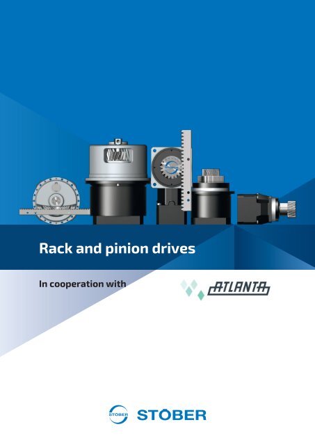
<strong>Rack</strong> and pinion drives<br />
In cooperation with
<strong>Rack</strong> and pinion drives
STOBER drive technology for<br />
perfectionists<br />
Sooner or later, design engineers never satisfied with the second-best solution end up at<br />
STOBER. That is because they can find everything here, with the broadest range of all<br />
imaginable drive technology components. Available with the highest level of design granularity<br />
to satisfy any individualized requirements perfectly. And the result is a complete STOBER<br />
system, from the gear rack and geared motor to open-loop or closed-loop control to intuitive<br />
project configuration software. With open interfaces based on established industry standards<br />
and reliably functioning communication between the individual components. The STOBER<br />
system also includes a complete package of services and practical support. Find out more on<br />
the following pages.<br />
You can put your trust in<br />
STOBER<br />
STOBER has been building excellent drive technology for more than<br />
80 years. As a medium-sized, owner-operated company, STOBER<br />
understands the needs of its customers. Our company is down-toearth,<br />
innovative, dynamic and focused on the customer. Our<br />
customers can find certified experts in every area, whether in<br />
research and development, production, technical consultation or<br />
design support. This goes beyond the technical qualifications. It also<br />
includes an equal measure of dedication, dependability and friendly,<br />
clear communication.<br />
2
3
STOBER in motion<br />
Despite our sense of tradition, we always enjoy something new.<br />
We continue to push ourselves forward and to refine our<br />
products further. We do this by implementing suggestions from<br />
real-world use, giving due consideration to customer requests and<br />
constantly seeking out even better solutions. This is all made<br />
possible by the competitive spirit with which we face every<br />
exciting challenge. The strong STOBER team spirit provides for<br />
productive collaboration. Both at work and outside the company<br />
doors. Our customers benefit from the extraordinary constancy of<br />
our employee base. This provides the astounding result where we<br />
can provide contacts familiar with a customer's industry and who<br />
can identify with a customer's needs.<br />
4
5
The team that works well together wins<br />
STOBER supplies the complete system: controller, automation,<br />
geared motors<br />
STOBER has its roots in developing and<br />
building geared motors. We have also been<br />
developing and manufacturing drive<br />
controllers for decades. These STOBER<br />
components form drive systems with<br />
dependable functionality thanks to their<br />
plug-and-play design. Electronics and<br />
mechanical systems that speak the same<br />
language are critical for this. They<br />
understand each other without any<br />
adapters. All of the system components can<br />
recognize each other by their "electronic<br />
nameplate."<br />
Systematic quality assurance<br />
We check every single component and how it works together with<br />
others. Mass-producers are not able to do that. We assume<br />
responsibility for the complete system. This means certified<br />
operational reliability and the highest machine availability are<br />
guaranteed.<br />
6
Technical system advantages<br />
The STOBER system is flexible. One ex<strong>amp</strong>le is the freedom to<br />
choose between drive-based mode and controller-based mode.<br />
Or the feature allowing you to combine drive controllers in a<br />
multi-axis drive system and stand-alone controllers with special<br />
functions as you wish. This allows the modular design and free<br />
scalability of a drive system. This enables full utilization of<br />
capacity.<br />
STOBER engineering software<br />
Our AS6 engineering software based on Codesys plays a leading<br />
role in the STOBER system. The AS6 has a whole series of new and<br />
useful features integrated into it that make your work easier in<br />
every phase of the project. Comprehensive libraries provide direct<br />
access to STOBER products from every level of the drive system.<br />
You can find detailed technical information and have ready access<br />
to presets for standard functions.<br />
STOBER is your partner<br />
Our role does not end with the delivery of hardware and software. If you like, we will accompany and<br />
support you throughout your entire project. You can call on programming manpower at STOBER. Our<br />
experienced Codesys professionals will be happy to handle tricky special tasks or help you find the right<br />
template. This is even possible if components from other manufacturers are part of the bigger picture.<br />
You have direct, one-on-one contact with your project engineer. Your personal contact understands<br />
your needs and works with you to find the ideal solution.<br />
You receive quick, professional feedback using the 24-<br />
hour hotline. You are not a number—you are our<br />
priority. We at STOBER do not have anything like a<br />
"service ticket."<br />
Dortmund<br />
Geographic proximity is also an intrinsic part of this personal contact. STOBER has four<br />
customer support centers throughout Germany. These support centers provide you with a<br />
high level of decision-making expertise. Your contacts have technical experience.<br />
And STOBER is international. We have 10 subsidiaries across 3 continents. This is also a<br />
valuable part of being near to our customers.<br />
Frankfurt<br />
Pforzheim<br />
Nürnberg<br />
7
Table of contents<br />
n 1 Selection tool ............................................................................................................................. 9<br />
n 2 ZTRSPH rack and pinion drives............................................................................................ 13<br />
n 3 ZTRSPHQ rack and pinion drives ......................................................................................... 31<br />
n 4 ZTRSPHV rack and pinion drives ........................................................................................ 43<br />
n 5 ZTRPH rack and pinion drives ............................................................................................. 55<br />
n 6 ZTRPHV rack and pinion drives........................................................................................... 79<br />
n 7 ZRPH rack and pinion drives................................................................................................. 91<br />
n 8 ZVP rack and pinion drives ................................................................................................ 109<br />
n 9 ZVPA rack and pinion drives............................................................................................... 125<br />
n 10 ZVPE rack and pinion drives ............................................................................................... 141<br />
n 11 ZVKS rack and pinion drives ............................................................................................... 155<br />
n 12 ZVKL rack and pinion drives ............................................................................................... 173<br />
n 13 ZVK rack and pinion drives ................................................................................................ 185<br />
n 14 Appendix................................................................................................................................. 209<br />
8
1.1 <strong>Rack</strong> and pinion drives<br />
1 Selection tool<br />
1.1 <strong>Rack</strong> and pinion drives<br />
Product chapter ZTRSPH ZTRSPHQ ZTRSPHV ZTRPH ZTRPHV ZRPH<br />
Chapter number [} 2] [} 3] [} 4] [} 5] [} 6] [} 7]<br />
Technical data<br />
m n 2 – 10 mm 8 – 10 mm 5 – 10 mm 2 – 8 mm 5 – 8 mm 2 – 4 mm<br />
z 15 – 32 15 – 19 15 – 20 12 – 32 12 – 19 26 – 45<br />
F f2acc 16 – 94 kN 124 – 126 kN 61 – 94 kN 5.8 – 67 kN 56 – 67 kN 1.7 – 13 kN<br />
v f2maxZB 0.17 – 4.7 m/s 0.06 – 1.1 m/s 0.2 – 0.62 m/s 0.09 – 4.7 m/s 0.19 – 0.39 m/s 0.23 – 6.7 m/s<br />
Δs 21 – 70 μm 69 – 70 μm 44 – 70 μm 11 – 44 μm 42 – 44 μm 31 – 56 μm<br />
An explanation of the formula symbols can be found in the chapter [} 14.1].<br />
Features<br />
Power density ★★★★★ ★★★★★ ★★★★★ ★★★★☆ ★★★★☆ ★★★☆☆<br />
Linear backlash ★★★★☆ ★★★★☆ ★★★★☆ ★★★★☆ ★★★★☆ ★★★☆☆<br />
Price category €€€€€ €€€€€ €€€€€ €€€€ €€€€ €€€<br />
Smooth operation ★★★★☆ ★★★★☆ ★★★★☆ ★★★★☆ ★★★★☆ ★★★★☆<br />
Linear rigidity ★★★★★ ★★★★★ ★★★★★ ★★★★☆ ★★★★☆ ★★★☆☆<br />
Mass moment of inertia ★★★★☆ ★★★★☆ ★★★★☆ ★★★★☆ ★★★★☆ ★★★★☆<br />
Key:<br />
★☆☆☆☆ good | ★★★★★ excellent<br />
€ Economy | €€€€€ Premium<br />
<strong>Pinion</strong> gearing<br />
Helical gearing ✓ ✓ ✓ ✓ ✓ ✓<br />
Gearing quality 5 5 5 5 5 5<br />
Accessories<br />
Felt gear ✓ ✓ ✓ ✓ ✓<br />
ATLANTA gear racks<br />
All gear racks suitable for our products are available from our cooperation partner, Atlanta.<br />
http://atlantagmbh.de/<br />
9
1 Selection tool<br />
1.1 <strong>Rack</strong> and pinion drives<br />
Product chapter ZVP ZVPA ZVPE<br />
Chapter number [} 8] [} 9] [} 10]<br />
Technical data<br />
m n 2 – 4 mm 2 – 4 mm 2 – 3 mm<br />
z 16 – 25 16 – 25 16 – 25<br />
F f2acc 2 – 15 kN 2 – 15 kN 2 – 6.3 kN<br />
v f2maxZB 0.14 – 4.9 m/s 0.14 – 4.9 m/s 0.11 – 4.5 m/s<br />
Δs 20 – 44 μm 8 – 22 μm 40 – 83 μm<br />
An explanation of the formula symbols can be found in the chapter [} 14.1].<br />
Features<br />
Power density ★★★☆☆ ★★★☆☆ ★★☆☆☆<br />
Linear backlash ★★★★☆ ★★★★★ ★★☆☆☆<br />
Price category €€ €€€ €<br />
Smooth operation ★★★★☆ ★★★★★ ★★★☆☆<br />
Linear rigidity ★★★☆☆ ★★★☆☆ ★★☆☆☆<br />
Mass moment of inertia ★★★★☆ ★★★★☆ ★★★★☆<br />
Key:<br />
★☆☆☆☆ good | ★★★★★ excellent<br />
€ Economy | €€€€€ Premium<br />
<strong>Pinion</strong> gearing<br />
Helical gearing ✓ ✓ ✓<br />
Gearing quality 7 7 7<br />
Bearing design<br />
Standard ✓ ✓<br />
Axially reinforced ✓ ✓<br />
ATLANTA gear racks<br />
All gear racks suitable for our products are available from our cooperation partner, Atlanta.<br />
http://atlantagmbh.de/<br />
10
1 Selection tool<br />
1.1 <strong>Rack</strong> and pinion drives<br />
Product chapter ZVKS ZVKL ZVK<br />
Chapter number [} 11] [} 12] [} 13]<br />
Technical data<br />
m n 2 – 4 mm 2 mm 2 – 4 mm<br />
z 18 – 25 16 – 20 18 – 25<br />
F f2acc 4.2 – 11 kN 1.3 – 2.9 kN 1.6 – 15 kN<br />
v f2maxZB 0.07 – 3 m/s 0.33 – 2.8 m/s 0.05 – 3.5 m/s<br />
Δs 31 – 44 μm 99 – 123 μm 12 – 111 μm<br />
An explanation of the formula symbols can be found in the chapter [} 14.1].<br />
Features<br />
Power density ★★★☆☆ ★★☆☆☆ ★☆☆☆☆<br />
Linear backlash ★★★☆☆ ★☆☆☆☆ ★★★☆☆<br />
Price category €€€ € €<br />
Smooth operation ★★★★☆ ★★☆☆☆ ★★★☆☆<br />
Linear rigidity ★★★☆☆ ★☆☆☆☆ ★☆☆☆☆<br />
Mass moment of inertia ★★★★☆ ★★★★☆ ★★★★☆<br />
Key:<br />
★☆☆☆☆ good | ★★★★★ excellent<br />
€ Economy | €€€€€ Premium<br />
<strong>Pinion</strong> gearing<br />
Helical gearing ✓ ✓ ✓<br />
Gearing quality 7 7 7<br />
ATLANTA gear racks<br />
All gear racks suitable for our products are available from our cooperation partner, Atlanta.<br />
http://atlantagmbh.de/<br />
11
1 Selection tool<br />
1.1 <strong>Rack</strong> and pinion drives<br />
12
2 ZTRSPH rack and pinion drives<br />
Table of contents<br />
2.1 Overview........................................................................................................................................................................... 14<br />
2.2 Selection tables ................................................................................................................................................................ 15<br />
2.3 Dimensional drawings ...................................................................................................................................................... 20<br />
2.4 Type designation .............................................................................................................................................................. 22<br />
2.4.1 Nameplate............................................................................................................................................................................ 23<br />
2.5 Product description........................................................................................................................................................... 23<br />
2.5.1 Motor adapter with EasyAdapt ® coupling (ME/MEL) ........................................................................................................... 23<br />
2.5.2 Input options........................................................................................................................................................................ 24<br />
2.5.3 Toothing ............................................................................................................................................................................... 24<br />
2.5.4 Installation conditions.......................................................................................................................................................... 24<br />
2.5.5 Lubricants............................................................................................................................................................................. 24<br />
2.5.6 Position of locking screw access........................................................................................................................................... 25<br />
2.5.7 Other product features ........................................................................................................................................................ 25<br />
2.5.8 Direction of rotation ............................................................................................................................................................ 25<br />
2.6 Project configuration......................................................................................................................................................... 25<br />
2.6.1 Drive selection...................................................................................................................................................................... 26<br />
2.6.2 Permitted breakdown torques at the gear unit input.......................................................................................................... 28<br />
2.6.3 Recommendation for radial shaft seal rings ........................................................................................................................ 28<br />
2.7 Additional documentation ................................................................................................................................................. 29<br />
13
2 <strong>Rack</strong> and pinion drives ZTRSPH<br />
2.1 Overview<br />
High-performance precision planetary gear units with<br />
supporting bearing holder<br />
Features<br />
Power density<br />
★★★★★<br />
Linear clearance<br />
★★★★☆<br />
Price category €€€€€<br />
Smooth operation<br />
★★★★☆<br />
Linear rigidity<br />
★★★★★<br />
Mass moment of inertia<br />
★★★★☆<br />
Ready-to-install drive solution<br />
✓<br />
<strong>Pinion</strong> gearing quality 5 (DIN 3962)<br />
✓<br />
Helical gearing<br />
✓<br />
Case-hardened and smoothed<br />
✓<br />
Radial runout ≤ 10 µm (optional)<br />
✓<br />
Key: ★☆☆☆☆ good | ★★★★★ excellent<br />
€ Economy | €€€€€ Premium<br />
Technical data<br />
m n<br />
2 – 10 mm<br />
z 15 – 32<br />
F f2acc<br />
v f2maxZB<br />
Δs<br />
16 – 94 kN<br />
0.17 – 4.7 m/s<br />
21 – 70 μm<br />
14
2 ZTRSPH rack and pinion drives 2.2 Selection tables<br />
2.2 Selection tables<br />
The technical data specified in the selection tables applies to:<br />
• De-energized installation<br />
• Permanent lubrication with the lubricants specified in the Atlanta product catalog<br />
• Material combinations as described in the chapter [} 2.5.3]<br />
• Installation altitudes up to 1000 m above sea level<br />
• Surrounding temperatures from 0 °C to 40 °C<br />
• Without consideration for thermal limiting performance<br />
For all other technical data, refer to http://configurator.stoeber.de.<br />
An explanation of the formula symbols can be found in the chapter [} 14.1].<br />
i Type n 1maxDB n 1maxZB d MW v f2maxZB Δs C lin m n z d 0 F f2N F f2acc F f2NOT M 2acc<br />
ZTRS2PH7 (F f2acc,max = 16 kN)<br />
[rpm] [rpm] [mm] [m/s] [mm] [N/μm] [mm] [mm] [kN] [kN] [kN] [Nm]<br />
4.000 ZTRS223SPH721_0040 ME 1900 4000 ≤38 2.56 0.021 173 2 23 48.8 7.1 16 32 390<br />
4.000 ZTRS223SPH721_0040 MEL 1900 4000 ≤48 2.56 0.021 177 2 23 48.8 7.1 16 32 390<br />
5.000 ZTRS223SPH721_0050 ME 2200 5000 ≤38 2.56 0.021 176 2 23 48.8 7.6 16 32 390<br />
5.000 ZTRS223SPH721_0050 MEL 2200 5000 ≤48 2.56 0.021 179 2 23 48.8 7.6 16 32 390<br />
7.000 ZTRS223SPH721_0070 ME 2500 5000 ≤38 1.83 0.021 174 2 23 48.8 8.5 16 32 390<br />
7.000 ZTRS223SPH721_0070 MEL 2500 5000 ≤48 1.83 0.021 175 2 23 48.8 8.5 16 32 390<br />
10.00 ZTRS223SPH721_0100 ME 3000 5000 ≤38 1.28 0.021 164 2 23 48.8 9.6 16 32 390<br />
10.00 ZTRS223SPH721_0100 MEL 3000 5000 ≤48 1.28 0.021 165 2 23 48.8 9.6 16 32 390<br />
16.00 ZTRS223SPH722_0160 ME 3000 5000 ≤32 0.80 0.021 170 2 23 48.8 11 16 32 390<br />
16.00 ZTRS223SPH722_0160 MEL 3000 5000 ≤38 0.80 0.021 171 2 23 48.8 11 16 32 390<br />
20.00 ZTRS223SPH722_0200 ME 3000 5000 ≤32 0.64 0.021 174 2 23 48.8 12 16 32 390<br />
20.00 ZTRS223SPH722_0200 MEL 3000 5000 ≤38 0.64 0.021 174 2 23 48.8 12 16 32 390<br />
25.00 ZTRS223SPH722_0250 ME 3500 6000 ≤32 0.61 0.021 174 2 23 48.8 13 16 32 390<br />
25.00 ZTRS223SPH722_0250 MEL 3500 6000 ≤38 0.61 0.021 174 2 23 48.8 13 16 32 390<br />
28.00 ZTRS223SPH722_0280 ME 3700 6500 ≤32 0.59 0.021 169 2 23 48.8 13 16 32 390<br />
28.00 ZTRS223SPH722_0280 MEL 3700 6500 ≤38 0.59 0.021 170 2 23 48.8 13 16 32 390<br />
35.00 ZTRS223SPH722_0350 ME 3700 6500 ≤32 0.48 0.021 174 2 23 48.8 13 16 32 390<br />
35.00 ZTRS223SPH722_0350 MEL 3700 6500 ≤38 0.48 0.021 174 2 23 48.8 13 16 32 390<br />
40.00 ZTRS223SPH722_0400 ME 3700 6500 ≤32 0.42 0.021 168 2 23 48.8 13 16 32 390<br />
40.00 ZTRS223SPH722_0400 MEL 3700 6500 ≤38 0.42 0.021 168 2 23 48.8 13 16 32 390<br />
50.00 ZTRS223SPH722_0500 ME 3700 6500 ≤32 0.33 0.021 173 2 23 48.8 13 16 32 390<br />
50.00 ZTRS223SPH722_0500 MEL 3700 6500 ≤38 0.33 0.021 173 2 23 48.8 13 16 32 390<br />
70.00 ZTRS223SPH722_0700 ME 3700 6500 ≤32 0.24 0.021 173 2 23 48.8 13 16 32 390<br />
70.00 ZTRS223SPH722_0700 MEL 3700 6500 ≤38 0.24 0.021 173 2 23 48.8 13 16 32 390<br />
100.0 ZTRS223SPH722_1000 ME 3700 6500 ≤32 0.17 0.021 164 2 23 48.8 12 16 32 390<br />
100.0 ZTRS223SPH722_1000 MEL 3700 6500 ≤38 0.17 0.021 164 2 23 48.8 12 16 32 390<br />
ZTRS3PH7 (F f2acc,max = 20 kN)<br />
4.000 ZTRS317SPH721_0040 ME 1900 4000 ≤38 2.83 0.024 170 3 17 54.1 7.0 20 36 550<br />
4.000 ZTRS317SPH721_0040 MEL 1900 4000 ≤48 2.83 0.024 174 3 17 54.1 7.0 20 36 550<br />
5.000 ZTRS317SPH721_0050 ME 2200 5000 ≤38 2.83 0.024 173 3 17 54.1 7.5 20 36 550<br />
5.000 ZTRS317SPH721_0050 MEL 2200 5000 ≤48 2.83 0.024 176 3 17 54.1 7.5 20 36 550<br />
7.000 ZTRS317SPH721_0070 ME 2500 5000 ≤38 2.02 0.024 170 3 17 54.1 8.4 20 36 550<br />
7.000 ZTRS317SPH721_0070 MEL 2500 5000 ≤48 2.02 0.024 172 3 17 54.1 8.4 20 36 550<br />
10.00 ZTRS317SPH721_0100 ME 3000 5000 ≤38 1.42 0.024 159 3 17 54.1 9.5 18 36 500<br />
10.00 ZTRS317SPH721_0100 MEL 3000 5000 ≤48 1.42 0.024 160 3 17 54.1 9.5 18 36 500<br />
16.00 ZTRS317SPH722_0160 ME 3000 5000 ≤32 0.89 0.024 166 3 17 54.1 11 20 36 550<br />
16.00 ZTRS317SPH722_0160 MEL 3000 5000 ≤38 0.89 0.024 167 3 17 54.1 11 20 36 550<br />
20.00 ZTRS317SPH722_0200 ME 3000 5000 ≤32 0.71 0.024 171 3 17 54.1 12 20 36 550<br />
20.00 ZTRS317SPH722_0200 MEL 3000 5000 ≤38 0.71 0.024 171 3 17 54.1 12 20 36 550<br />
25.00 ZTRS317SPH722_0250 ME 3500 6000 ≤32 0.68 0.024 171 3 17 54.1 13 20 36 550<br />
25.00 ZTRS317SPH722_0250 MEL 3500 6000 ≤38 0.68 0.024 171 3 17 54.1 13 20 36 550<br />
28.00 ZTRS317SPH722_0280 ME 3700 6500 ≤32 0.66 0.024 165 3 17 54.1 13 20 36 550<br />
28.00 ZTRS317SPH722_0280 MEL 3700 6500 ≤38 0.66 0.024 165 3 17 54.1 13 20 36 550<br />
35.00 ZTRS317SPH722_0350 ME 3700 6500 ≤32 0.53 0.024 170 3 17 54.1 13 20 36 550<br />
35.00 ZTRS317SPH722_0350 MEL 3700 6500 ≤38 0.53 0.024 170 3 17 54.1 13 20 36 550<br />
40.00 ZTRS317SPH722_0400 ME 3700 6500 ≤32 0.46 0.024 164 3 17 54.1 13 20 36 550<br />
40.00 ZTRS317SPH722_0400 MEL 3700 6500 ≤38 0.46 0.024 164 3 17 54.1 13 20 36 550<br />
50.00 ZTRS317SPH722_0500 ME 3700 6500 ≤32 0.37 0.024 169 3 17 54.1 13 20 36 550<br />
50.00 ZTRS317SPH722_0500 MEL 3700 6500 ≤38 0.37 0.024 169 3 17 54.1 13 20 36 550<br />
70.00 ZTRS317SPH722_0700 ME 3700 6500 ≤32 0.26 0.024 169 3 17 54.1 13 20 36 550<br />
15
2.2 Selection tables 2 ZTRSPH rack and pinion drives<br />
16<br />
i Type n 1maxDB n 1maxZB d MW v f2maxZB Δs C lin m n z d 0 F f2N F f2acc F f2NOT M 2acc<br />
ZTRS3PH7 (F f2acc,max = 20 kN)<br />
[rpm] [rpm] [mm] [m/s] [mm] [N/μm] [mm] [mm] [kN] [kN] [kN] [Nm]<br />
70.00 ZTRS317SPH722_0700 MEL 3700 6500 ≤38 0.26 0.024 169 3 17 54.1 13 20 36 550<br />
100.0 ZTRS317SPH722_1000 ME 3700 6500 ≤32 0.18 0.024 158 3 17 54.1 11 18 36 500<br />
100.0 ZTRS317SPH722_1000 MEL 3700 6500 ≤38 0.18 0.024 158 3 17 54.1 11 18 36 500<br />
ZTRS3PH8 (F f2acc,max = 28 kN)<br />
4.000 ZTRS326SPH821_0040 ME 1500 3500 ≤48 3.79 0.036 241 3 26 82.8 18 27 55 1130<br />
4.000 ZTRS326SPH821_0040 MEL 1500 3500 ≤55 3.79 0.036 260 3 26 82.8 18 27 55 1130<br />
4.000 ZTRS332SPH821_0040 ME 1500 3500 ≤48 4.67 0.044 212 3 32 101.9 17 28 45 1410<br />
4.000 ZTRS332SPH821_0040 MEL 1500 3500 ≤55 4.67 0.044 235 3 32 101.9 17 28 45 1410<br />
5.000 ZTRS326SPH821_0050 ME 1700 4000 ≤48 3.47 0.036 244 3 26 82.8 19 27 55 1130<br />
5.000 ZTRS326SPH821_0050 MEL 1700 4000 ≤55 3.47 0.036 257 3 26 82.8 19 27 55 1130<br />
5.000 ZTRS332SPH821_0050 ME 1700 4000 ≤48 4.27 0.044 216 3 32 101.9 19 28 49 1410<br />
5.000 ZTRS332SPH821_0050 MEL 1700 4000 ≤55 4.27 0.044 230 3 32 101.9 19 28 49 1410<br />
7.000 ZTRS326SPH821_0070 ME 2000 4000 ≤48 2.48 0.036 241 3 26 82.8 22 27 55 1130<br />
7.000 ZTRS326SPH821_0070 MEL 2000 4000 ≤55 2.48 0.036 248 3 26 82.8 22 27 55 1130<br />
7.000 ZTRS332SPH821_0070 ME 2000 4000 ≤48 3.05 0.044 211 3 32 101.9 20 28 49 1410<br />
7.000 ZTRS332SPH821_0070 MEL 2000 4000 ≤55 3.05 0.044 220 3 32 101.9 20 28 49 1410<br />
10.00 ZTRS326SPH821_0100 ME 2500 4000 ≤48 1.73 0.036 218 3 26 82.8 19 27 55 1130<br />
10.00 ZTRS326SPH821_0100 MEL 2500 4000 ≤55 1.73 0.036 221 3 26 82.8 19 27 55 1130<br />
10.00 ZTRS332SPH821_0100 ME 2500 4000 ≤48 2.13 0.044 185 3 32 101.9 16 24 47 1200<br />
10.00 ZTRS332SPH821_0100 MEL 2500 4000 ≤55 2.13 0.044 189 3 32 101.9 16 24 47 1200<br />
16.00 ZTRS326SPH822_0160 ME 2500 4500 ≤38 1.22 0.036 244 3 26 82.8 27 27 55 1130<br />
16.00 ZTRS326SPH822_0160 MEL 2500 4500 ≤48 1.22 0.036 246 3 26 82.8 27 27 55 1130<br />
16.00 ZTRS332SPH822_0160 ME 2500 4500 ≤38 1.50 0.044 215 3 32 101.9 22 28 49 1410<br />
16.00 ZTRS332SPH822_0160 MEL 2500 4500 ≤48 1.50 0.044 217 3 32 101.9 22 28 49 1410<br />
20.00 ZTRS326SPH822_0200 ME 2500 4500 ≤38 0.98 0.036 246 3 26 82.8 27 27 55 1130<br />
20.00 ZTRS326SPH822_0200 MEL 2500 4500 ≤48 0.98 0.036 247 3 26 82.8 27 27 55 1130<br />
20.00 ZTRS332SPH822_0200 ME 2500 4500 ≤38 1.20 0.044 218 3 32 101.9 25 28 49 1410<br />
20.00 ZTRS332SPH822_0200 MEL 2500 4500 ≤48 1.20 0.044 219 3 32 101.9 25 28 49 1410<br />
25.00 ZTRS326SPH822_0250 ME 3000 5500 ≤38 0.95 0.036 251 3 26 82.8 27 27 55 1130<br />
25.00 ZTRS326SPH822_0250 MEL 3000 5500 ≤48 0.95 0.036 251 3 26 82.8 27 27 55 1130<br />
25.00 ZTRS332SPH822_0250 ME 3000 5500 ≤38 1.17 0.044 223 3 32 101.9 25 28 49 1410<br />
25.00 ZTRS332SPH822_0250 MEL 3000 5500 ≤48 1.17 0.044 224 3 32 101.9 25 28 49 1410<br />
28.00 ZTRS326SPH822_0280 ME 3300 6000 ≤38 0.93 0.036 243 3 26 82.8 27 27 55 1130<br />
28.00 ZTRS326SPH822_0280 MEL 3300 6000 ≤48 0.93 0.036 244 3 26 82.8 27 27 55 1130<br />
28.00 ZTRS332SPH822_0280 ME 3300 6000 ≤38 1.14 0.044 214 3 32 101.9 22 28 49 1410<br />
28.00 ZTRS332SPH822_0280 MEL 3300 6000 ≤48 1.14 0.044 215 3 32 101.9 22 28 49 1410<br />
35.00 ZTRS326SPH822_0350 ME 3300 6000 ≤38 0.74 0.036 246 3 26 82.8 27 27 55 1130<br />
35.00 ZTRS326SPH822_0350 MEL 3300 6000 ≤48 0.74 0.036 246 3 26 82.8 27 27 55 1130<br />
35.00 ZTRS332SPH822_0350 ME 3300 6000 ≤38 0.91 0.044 217 3 32 101.9 25 28 49 1410<br />
35.00 ZTRS332SPH822_0350 MEL 3300 6000 ≤48 0.91 0.044 218 3 32 101.9 25 28 49 1410<br />
40.00 ZTRS326SPH822_0400 ME 3300 6000 ≤38 0.65 0.036 241 3 26 82.8 27 27 55 1130<br />
40.00 ZTRS326SPH822_0400 MEL 3300 6000 ≤48 0.65 0.036 241 3 26 82.8 27 27 55 1130<br />
40.00 ZTRS332SPH822_0400 ME 3300 6000 ≤38 0.80 0.044 212 3 32 101.9 22 28 49 1410<br />
40.00 ZTRS332SPH822_0400 MEL 3300 6000 ≤48 0.80 0.044 212 3 32 101.9 22 28 49 1410<br />
50.00 ZTRS326SPH822_0500 ME 3300 6000 ≤38 0.52 0.036 244 3 26 82.8 27 27 55 1130<br />
50.00 ZTRS326SPH822_0500 MEL 3300 6000 ≤48 0.52 0.036 245 3 26 82.8 27 27 55 1130<br />
50.00 ZTRS332SPH822_0500 ME 3300 6000 ≤38 0.64 0.044 216 3 32 101.9 25 28 49 1410<br />
50.00 ZTRS332SPH822_0500 MEL 3300 6000 ≤48 0.64 0.044 216 3 32 101.9 25 28 49 1410<br />
70.00 ZTRS326SPH822_0700 ME 3300 6000 ≤38 0.37 0.036 242 3 26 82.8 24 27 55 1130<br />
70.00 ZTRS326SPH822_0700 MEL 3300 6000 ≤48 0.37 0.036 242 3 26 82.8 24 27 55 1130<br />
70.00 ZTRS332SPH822_0700 ME 3300 6000 ≤38 0.46 0.044 213 3 32 101.9 20 28 49 1410<br />
70.00 ZTRS332SPH822_0700 MEL 3300 6000 ≤48 0.46 0.044 213 3 32 101.9 20 28 49 1410<br />
100.0 ZTRS326SPH822_1000 ME 3300 6000 ≤38 0.26 0.036 218 3 26 82.8 19 27 55 1130<br />
100.0 ZTRS326SPH822_1000 MEL 3300 6000 ≤48 0.26 0.036 218 3 26 82.8 19 27 55 1130<br />
100.0 ZTRS332SPH822_1000 ME 3300 6000 ≤38 0.32 0.044 186 3 32 101.9 16 24 47 1200<br />
100.0 ZTRS332SPH822_1000 MEL 3300 6000 ≤48 0.32 0.044 186 3 32 101.9 16 24 47 1200<br />
ZTRS4PH8 (F f2acc,max = 45 kN)<br />
4.000 ZTRS420SPH821_0040 ME 1500 3500 ≤48 3.89 0.037 263 4 20 84.9 18 38 54 1600<br />
4.000 ZTRS420SPH821_0040 MEL 1500 3500 ≤55 3.89 0.037 288 4 20 84.9 18 38 54 1600<br />
5.000 ZTRS420SPH821_0050 ME 1700 4000 ≤48 3.56 0.037 268 4 20 84.9 19 40 56 1700<br />
5.000 ZTRS420SPH821_0050 MEL 1700 4000 ≤55 3.56 0.037 283 4 20 84.9 19 40 56 1700<br />
7.000 ZTRS420SPH821_0070 ME 2000 4000 ≤48 2.54 0.037 263 4 20 84.9 22 38 56 1600<br />
7.000 ZTRS420SPH821_0070 MEL 2000 4000 ≤55 2.54 0.037 272 4 20 84.9 22 38 56 1600<br />
10.00 ZTRS420SPH821_0100 ME 2500 4000 ≤48 1.78 0.037 235 4 20 84.9 19 28 56 1200<br />
10.00 ZTRS420SPH821_0100 MEL 2500 4000 ≤55 1.78 0.037 238 4 20 84.9 19 28 56 1200<br />
16.00 ZTRS420SPH822_0160 ME 2500 4500 ≤38 1.25 0.037 267 4 20 84.9 26 45 56 1900
2 ZTRSPH rack and pinion drives 2.2 Selection tables<br />
i Type n 1maxDB n 1maxZB d MW v f2maxZB Δs C lin m n z d 0 F f2N F f2acc F f2NOT M 2acc<br />
ZTRS4PH8 (F f2acc,max = 45 kN)<br />
[rpm] [rpm] [mm] [m/s] [mm] [N/μm] [mm] [mm] [kN] [kN] [kN] [Nm]<br />
16.00 ZTRS420SPH822_0160 MEL 2500 4500 ≤48 1.25 0.037 269 4 20 84.9 26 45 56 1900<br />
20.00 ZTRS420SPH822_0200 ME 2500 4500 ≤38 1.00 0.037 270 4 20 84.9 29 45 56 1900<br />
20.00 ZTRS420SPH822_0200 MEL 2500 4500 ≤48 1.00 0.037 271 4 20 84.9 29 45 56 1900<br />
25.00 ZTRS420SPH822_0250 ME 3000 5500 ≤38 0.98 0.037 275 4 20 84.9 29 45 56 1900<br />
25.00 ZTRS420SPH822_0250 MEL 3000 5500 ≤48 0.98 0.037 276 4 20 84.9 29 45 56 1900<br />
28.00 ZTRS420SPH822_0280 ME 3300 6000 ≤38 0.95 0.037 266 4 20 84.9 26 45 56 1900<br />
28.00 ZTRS420SPH822_0280 MEL 3300 6000 ≤48 0.95 0.037 267 4 20 84.9 26 45 56 1900<br />
35.00 ZTRS420SPH822_0350 ME 3300 6000 ≤38 0.76 0.037 270 4 20 84.9 29 45 56 1900<br />
35.00 ZTRS420SPH822_0350 MEL 3300 6000 ≤48 0.76 0.037 270 4 20 84.9 29 45 56 1900<br />
40.00 ZTRS420SPH822_0400 ME 3300 6000 ≤38 0.67 0.037 264 4 20 84.9 26 45 56 1900<br />
40.00 ZTRS420SPH822_0400 MEL 3300 6000 ≤48 0.67 0.037 264 4 20 84.9 26 45 56 1900<br />
50.00 ZTRS420SPH822_0500 ME 3300 6000 ≤38 0.53 0.037 268 4 20 84.9 29 45 56 1900<br />
50.00 ZTRS420SPH822_0500 MEL 3300 6000 ≤48 0.53 0.037 268 4 20 84.9 29 45 56 1900<br />
70.00 ZTRS420SPH822_0700 ME 3300 6000 ≤38 0.38 0.037 265 4 20 84.9 24 38 56 1600<br />
70.00 ZTRS420SPH822_0700 MEL 3300 6000 ≤48 0.38 0.037 265 4 20 84.9 24 38 56 1600<br />
100.0 ZTRS420SPH822_1000 ME 3300 6000 ≤38 0.27 0.037 235 4 20 84.9 19 28 56 1200<br />
100.0 ZTRS420SPH822_1000 MEL 3300 6000 ≤48 0.27 0.037 235 4 20 84.9 19 28 56 1200<br />
ZTRS5PH8 (F f2acc,max = 43 kN)<br />
4.000 ZTRS516SPH821_0040 ME 1500 3500 ≤48 3.89 0.037 273 5 16 84.9 18 38 54 1600<br />
4.000 ZTRS516SPH821_0040 MEL 1500 3500 ≤55 3.89 0.037 299 5 16 84.9 18 38 54 1600<br />
5.000 ZTRS516SPH821_0050 ME 1700 4000 ≤48 3.56 0.037 277 5 16 84.9 19 40 54 1700<br />
5.000 ZTRS516SPH821_0050 MEL 1700 4000 ≤55 3.56 0.037 294 5 16 84.9 19 40 54 1700<br />
7.000 ZTRS516SPH821_0070 ME 2000 4000 ≤48 2.54 0.037 272 5 16 84.9 22 38 54 1600<br />
7.000 ZTRS516SPH821_0070 MEL 2000 4000 ≤55 2.54 0.037 282 5 16 84.9 22 38 54 1600<br />
10.00 ZTRS516SPH821_0100 ME 2500 4000 ≤48 1.78 0.037 242 5 16 84.9 19 28 54 1200<br />
10.00 ZTRS516SPH821_0100 MEL 2500 4000 ≤55 1.78 0.037 246 5 16 84.9 19 28 54 1200<br />
16.00 ZTRS516SPH822_0160 ME 2500 4500 ≤38 1.25 0.037 277 5 16 84.9 26 43 54 1840<br />
16.00 ZTRS516SPH822_0160 MEL 2500 4500 ≤48 1.25 0.037 279 5 16 84.9 26 43 54 1840<br />
20.00 ZTRS516SPH822_0200 ME 2500 4500 ≤38 1.00 0.037 280 5 16 84.9 29 43 54 1840<br />
20.00 ZTRS516SPH822_0200 MEL 2500 4500 ≤48 1.00 0.037 281 5 16 84.9 29 43 54 1840<br />
25.00 ZTRS516SPH822_0250 ME 3000 5500 ≤38 0.98 0.037 286 5 16 84.9 29 43 54 1840<br />
25.00 ZTRS516SPH822_0250 MEL 3000 5500 ≤48 0.98 0.037 287 5 16 84.9 29 43 54 1840<br />
28.00 ZTRS516SPH822_0280 ME 3300 6000 ≤38 0.95 0.037 276 5 16 84.9 26 43 54 1840<br />
28.00 ZTRS516SPH822_0280 MEL 3300 6000 ≤48 0.95 0.037 277 5 16 84.9 26 43 54 1840<br />
35.00 ZTRS516SPH822_0350 ME 3300 6000 ≤38 0.76 0.037 279 5 16 84.9 29 43 54 1840<br />
35.00 ZTRS516SPH822_0350 MEL 3300 6000 ≤48 0.76 0.037 280 5 16 84.9 29 43 54 1840<br />
40.00 ZTRS516SPH822_0400 ME 3300 6000 ≤38 0.67 0.037 273 5 16 84.9 26 43 54 1840<br />
40.00 ZTRS516SPH822_0400 MEL 3300 6000 ≤48 0.67 0.037 274 5 16 84.9 26 43 54 1840<br />
50.00 ZTRS516SPH822_0500 ME 3300 6000 ≤38 0.53 0.037 278 5 16 84.9 29 43 54 1840<br />
50.00 ZTRS516SPH822_0500 MEL 3300 6000 ≤48 0.53 0.037 278 5 16 84.9 29 43 54 1840<br />
70.00 ZTRS516SPH822_0700 ME 3300 6000 ≤38 0.38 0.037 274 5 16 84.9 24 38 54 1600<br />
70.00 ZTRS516SPH822_0700 MEL 3300 6000 ≤48 0.38 0.037 274 5 16 84.9 24 38 54 1600<br />
100.0 ZTRS516SPH822_1000 ME 3300 6000 ≤38 0.27 0.037 243 5 16 84.9 19 28 54 1200<br />
100.0 ZTRS516SPH822_1000 MEL 3300 6000 ≤48 0.27 0.037 243 5 16 84.9 19 28 54 1200<br />
ZTRS5PH9 (F f2acc,max = 77 kN)<br />
12.00 ZTRS520SPH932_0120 ME 1800 3000 ≤48 1.39 0.046 388 5 20 106.1 39 77 127 4080<br />
12.00 ZTRS520SPH932_0120 MEL 1800 3000 ≤60 1.39 0.046 396 5 20 106.1 39 77 127 4080<br />
16.00 ZTRS520SPH932_0160 ME 2200 3500 ≤48 1.22 0.046 391 5 20 106.1 43 77 154 4080<br />
16.00 ZTRS520SPH932_0160 MEL 2200 3500 ≤60 1.22 0.046 395 5 20 106.1 43 77 154 4080<br />
18.00 ZTRS520SPH932_0180 ME 1800 3000 ≤48 0.93 0.046 385 5 20 106.1 45 77 154 4080<br />
18.00 ZTRS520SPH932_0180 MEL 1800 3000 ≤60 0.93 0.046 389 5 20 106.1 45 77 154 4080<br />
20.00 ZTRS520SPH932_0200 ME 2500 4000 ≤48 1.11 0.046 391 5 20 106.1 47 77 154 4080<br />
20.00 ZTRS520SPH932_0200 MEL 2500 4000 ≤60 1.11 0.046 394 5 20 106.1 47 77 154 4080<br />
24.00 ZTRS520SPH932_0240 ME 2200 3500 ≤48 0.81 0.046 386 5 20 106.1 50 77 154 4080<br />
24.00 ZTRS520SPH932_0240 MEL 2200 3500 ≤60 0.81 0.046 388 5 20 106.1 50 77 154 4080<br />
28.00 ZTRS520SPH932_0280 ME 2800 4500 ≤48 0.89 0.046 389 5 20 106.1 50 77 154 4080<br />
28.00 ZTRS520SPH932_0280 MEL 2800 4500 ≤55 0.89 0.046 391 5 20 106.1 50 77 154 4080<br />
30.00 ZTRS520SPH932_0300 ME 2500 4000 ≤48 0.74 0.046 386 5 20 106.1 50 77 154 4080<br />
30.00 ZTRS520SPH932_0300 MEL 2500 4000 ≤60 0.74 0.046 388 5 20 106.1 50 77 154 4080<br />
32.00 ZTRS520SPH932_0320 ME 2800 4500 ≤48 0.78 0.046 386 5 20 106.1 50 77 154 4080<br />
32.00 ZTRS520SPH932_0320 MEL 2800 4500 ≤55 0.78 0.046 387 5 20 106.1 50 77 154 4080<br />
40.00 ZTRS520SPH932_0400 ME 2800 4500 ≤48 0.63 0.046 381 5 20 106.1 50 77 154 4080<br />
40.00 ZTRS520SPH932_0400 MEL 2800 4500 ≤55 0.63 0.046 382 5 20 106.1 50 77 154 4080<br />
42.00 ZTRS520SPH932_0420 ME 2800 4500 ≤48 0.60 0.046 386 5 20 106.1 50 77 154 4080<br />
42.00 ZTRS520SPH932_0420 MEL 2800 4500 ≤55 0.60 0.046 386 5 20 106.1 50 77 154 4080<br />
48.00 ZTRS520SPH932_0480 ME 2800 4500 ≤48 0.52 0.046 384 5 20 106.1 50 77 154 4080<br />
17
2.2 Selection tables 2 ZTRSPH rack and pinion drives<br />
18<br />
i Type n 1maxDB n 1maxZB d MW v f2maxZB Δs C lin m n z d 0 F f2N F f2acc F f2NOT M 2acc<br />
ZTRS5PH9 (F f2acc,max = 77 kN)<br />
[rpm] [rpm] [mm] [m/s] [mm] [N/μm] [mm] [mm] [kN] [kN] [kN] [Nm]<br />
48.00 ZTRS520SPH932_0480 MEL 2800 4500 ≤55 0.52 0.046 385 5 20 106.1 50 77 154 4080<br />
60.00 ZTRS520SPH932_0600 ME 2800 4500 ≤48 0.42 0.046 382 5 20 106.1 50 77 154 4080<br />
60.00 ZTRS520SPH932_0600 MEL 2800 4500 ≤55 0.42 0.046 383 5 20 106.1 50 77 154 4080<br />
ZTRS6PH9 (F f2acc,max = 77 kN)<br />
12.00 ZTRS616SPH932_0120 ME 1800 3000 ≤48 1.33 0.044 410 6 16 101.9 39 61 122 3100<br />
12.00 ZTRS616SPH932_0120 MEL 1800 3000 ≤60 1.33 0.044 419 6 16 101.9 39 61 122 3100<br />
12.00 ZTRS620SPH932_0120 ME 1800 3000 ≤48 1.67 0.056 360 6 20 127.3 39 72 106 4610<br />
12.00 ZTRS620SPH932_0120 MEL 1800 3000 ≤60 1.67 0.056 371 6 20 127.3 39 72 106 4610<br />
16.00 ZTRS616SPH932_0160 ME 2200 3500 ≤48 1.17 0.044 413 6 16 101.9 43 61 122 3100<br />
16.00 ZTRS616SPH932_0160 MEL 2200 3500 ≤60 1.17 0.044 418 6 16 101.9 43 61 122 3100<br />
16.00 ZTRS620SPH932_0160 ME 2200 3500 ≤48 1.46 0.056 363 6 20 127.3 43 77 141 4920<br />
16.00 ZTRS620SPH932_0160 MEL 2200 3500 ≤60 1.46 0.056 369 6 20 127.3 43 77 141 4920<br />
18.00 ZTRS616SPH932_0180 ME 1800 3000 ≤48 0.89 0.044 407 6 16 101.9 45 61 122 3100<br />
18.00 ZTRS616SPH932_0180 MEL 1800 3000 ≤60 0.89 0.044 411 6 16 101.9 45 61 122 3100<br />
18.00 ZTRS620SPH932_0180 ME 1800 3000 ≤48 1.11 0.056 357 6 20 127.3 44 71 141 4500<br />
18.00 ZTRS620SPH932_0180 MEL 1800 3000 ≤60 1.11 0.056 361 6 20 127.3 44 71 141 4500<br />
20.00 ZTRS616SPH932_0200 ME 2500 4000 ≤48 1.07 0.044 413 6 16 101.9 47 61 122 3100<br />
20.00 ZTRS616SPH932_0200 MEL 2500 4000 ≤60 1.07 0.044 416 6 16 101.9 47 61 122 3100<br />
20.00 ZTRS620SPH932_0200 ME 2500 4000 ≤48 1.33 0.056 364 6 20 127.3 46 77 144 4920<br />
20.00 ZTRS620SPH932_0200 MEL 2500 4000 ≤60 1.33 0.056 368 6 20 127.3 46 77 144 4920<br />
24.00 ZTRS616SPH932_0240 ME 2200 3500 ≤48 0.78 0.044 408 6 16 101.9 50 61 122 3100<br />
24.00 ZTRS616SPH932_0240 MEL 2200 3500 ≤60 0.78 0.044 410 6 16 101.9 50 61 122 3100<br />
24.00 ZTRS620SPH932_0240 ME 2200 3500 ≤48 0.97 0.056 358 6 20 127.3 47 71 141 4500<br />
24.00 ZTRS620SPH932_0240 MEL 2200 3500 ≤60 0.97 0.056 361 6 20 127.3 47 71 141 4500<br />
28.00 ZTRS616SPH932_0280 ME 2800 4500 ≤48 0.86 0.044 411 6 16 101.9 50 61 122 3100<br />
28.00 ZTRS616SPH932_0280 MEL 2800 4500 ≤55 0.86 0.044 413 6 16 101.9 50 61 122 3100<br />
28.00 ZTRS620SPH932_0280 ME 2800 4500 ≤48 1.07 0.056 361 6 20 127.3 47 77 144 4920<br />
28.00 ZTRS620SPH932_0280 MEL 2800 4500 ≤55 1.07 0.056 364 6 20 127.3 47 77 144 4920<br />
30.00 ZTRS616SPH932_0300 ME 2500 4000 ≤48 0.71 0.044 408 6 16 101.9 50 61 122 3100<br />
30.00 ZTRS616SPH932_0300 MEL 2500 4000 ≤60 0.71 0.044 410 6 16 101.9 50 61 122 3100<br />
30.00 ZTRS620SPH932_0300 ME 2500 4000 ≤48 0.89 0.056 358 6 20 127.3 47 71 141 4500<br />
30.00 ZTRS620SPH932_0300 MEL 2500 4000 ≤60 0.89 0.056 360 6 20 127.3 47 71 141 4500<br />
32.00 ZTRS616SPH932_0320 ME 2800 4500 ≤48 0.75 0.044 408 6 16 101.9 50 61 122 3100<br />
32.00 ZTRS616SPH932_0320 MEL 2800 4500 ≤55 0.75 0.044 409 6 16 101.9 50 61 122 3100<br />
32.00 ZTRS620SPH932_0320 ME 2800 4500 ≤48 0.94 0.056 358 6 20 127.3 47 72 144 4610<br />
32.00 ZTRS620SPH932_0320 MEL 2800 4500 ≤55 0.94 0.056 360 6 20 127.3 47 72 144 4610<br />
40.00 ZTRS616SPH932_0400 ME 2800 4500 ≤48 0.60 0.044 403 6 16 101.9 50 61 122 3100<br />
40.00 ZTRS616SPH932_0400 MEL 2800 4500 ≤55 0.60 0.044 404 6 16 101.9 50 61 122 3100<br />
40.00 ZTRS620SPH932_0400 ME 2800 4500 ≤48 0.75 0.056 352 6 20 127.3 42 72 144 4610<br />
40.00 ZTRS620SPH932_0400 MEL 2800 4500 ≤55 0.75 0.056 353 6 20 127.3 42 72 144 4610<br />
42.00 ZTRS616SPH932_0420 ME 2800 4500 ≤48 0.57 0.044 407 6 16 101.9 50 61 122 3100<br />
42.00 ZTRS616SPH932_0420 MEL 2800 4500 ≤55 0.57 0.044 408 6 16 101.9 50 61 122 3100<br />
42.00 ZTRS620SPH932_0420 ME 2800 4500 ≤48 0.71 0.056 357 6 20 127.3 47 71 141 4500<br />
42.00 ZTRS620SPH932_0420 MEL 2800 4500 ≤55 0.71 0.056 358 6 20 127.3 47 71 141 4500<br />
48.00 ZTRS616SPH932_0480 ME 2800 4500 ≤48 0.50 0.044 406 6 16 101.9 50 61 122 3100<br />
48.00 ZTRS616SPH932_0480 MEL 2800 4500 ≤55 0.50 0.044 407 6 16 101.9 50 61 122 3100<br />
48.00 ZTRS620SPH932_0480 ME 2800 4500 ≤48 0.63 0.056 356 6 20 127.3 47 71 141 4500<br />
48.00 ZTRS620SPH932_0480 MEL 2800 4500 ≤55 0.63 0.056 356 6 20 127.3 47 71 141 4500<br />
60.00 ZTRS616SPH932_0600 ME 2800 4500 ≤48 0.40 0.044 404 6 16 101.9 50 61 122 3100<br />
60.00 ZTRS616SPH932_0600 MEL 2800 4500 ≤55 0.40 0.044 404 6 16 101.9 50 61 122 3100<br />
60.00 ZTRS620SPH932_0600 ME 2800 4500 ≤48 0.50 0.056 353 6 20 127.3 47 71 141 4500<br />
60.00 ZTRS620SPH932_0600 MEL 2800 4500 ≤55 0.50 0.056 353 6 20 127.3 47 71 141 4500<br />
ZTRS8PH9 (F f2acc,max = 79 kN)<br />
12.00 ZTRS815SPH932_0120 ME 1800 3000 ≤48 1.67 0.056 377 8 15 127.3 39 72 106 4610<br />
12.00 ZTRS815SPH932_0120 MEL 1800 3000 ≤60 1.67 0.056 389 8 15 127.3 39 72 106 4610<br />
16.00 ZTRS815SPH932_0160 ME 2200 3500 ≤48 1.46 0.056 381 8 15 127.3 43 79 141 5000<br />
16.00 ZTRS815SPH932_0160 MEL 2200 3500 ≤60 1.46 0.056 388 8 15 127.3 43 79 141 5000<br />
18.00 ZTRS815SPH932_0180 ME 1800 3000 ≤48 1.11 0.056 373 8 15 127.3 44 71 141 4500<br />
18.00 ZTRS815SPH932_0180 MEL 1800 3000 ≤60 1.11 0.056 378 8 15 127.3 44 71 141 4500<br />
20.00 ZTRS815SPH932_0200 ME 2500 4000 ≤48 1.33 0.056 381 8 15 127.3 46 79 141 5000<br />
20.00 ZTRS815SPH932_0200 MEL 2500 4000 ≤60 1.33 0.056 385 8 15 127.3 46 79 141 5000<br />
24.00 ZTRS815SPH932_0240 ME 2200 3500 ≤48 0.97 0.056 375 8 15 127.3 47 71 141 4500<br />
24.00 ZTRS815SPH932_0240 MEL 2200 3500 ≤60 0.97 0.056 378 8 15 127.3 47 71 141 4500<br />
28.00 ZTRS815SPH932_0280 ME 2800 4500 ≤48 1.07 0.056 378 8 15 127.3 47 79 141 5000<br />
28.00 ZTRS815SPH932_0280 MEL 2800 4500 ≤55 1.07 0.056 381 8 15 127.3 47 79 141 5000<br />
30.00 ZTRS815SPH932_0300 ME 2500 4000 ≤48 0.89 0.056 375 8 15 127.3 47 71 141 4500
2 ZTRSPH rack and pinion drives 2.2 Selection tables<br />
i Type n 1maxDB n 1maxZB d MW v f2maxZB Δs C lin m n z d 0 F f2N F f2acc F f2NOT M 2acc<br />
ZTRS8PH9 (F f2acc,max = 79 kN)<br />
[rpm] [rpm] [mm] [m/s] [mm] [N/μm] [mm] [mm] [kN] [kN] [kN] [Nm]<br />
30.00 ZTRS815SPH932_0300 MEL 2500 4000 ≤60 0.89 0.056 377 8 15 127.3 47 71 141 4500<br />
32.00 ZTRS815SPH932_0320 ME 2800 4500 ≤48 0.94 0.056 375 8 15 127.3 47 72 141 4610<br />
32.00 ZTRS815SPH932_0320 MEL 2800 4500 ≤55 0.94 0.056 377 8 15 127.3 47 72 141 4610<br />
40.00 ZTRS815SPH932_0400 ME 2800 4500 ≤48 0.75 0.056 368 8 15 127.3 42 72 141 4610<br />
40.00 ZTRS815SPH932_0400 MEL 2800 4500 ≤55 0.75 0.056 369 8 15 127.3 42 72 141 4610<br />
42.00 ZTRS815SPH932_0420 ME 2800 4500 ≤48 0.71 0.056 374 8 15 127.3 47 71 141 4500<br />
42.00 ZTRS815SPH932_0420 MEL 2800 4500 ≤55 0.71 0.056 375 8 15 127.3 47 71 141 4500<br />
48.00 ZTRS815SPH932_0480 ME 2800 4500 ≤48 0.63 0.056 372 8 15 127.3 47 71 141 4500<br />
48.00 ZTRS815SPH932_0480 MEL 2800 4500 ≤55 0.63 0.056 373 8 15 127.3 47 71 141 4500<br />
60.00 ZTRS815SPH932_0600 ME 2800 4500 ≤48 0.50 0.056 369 8 15 127.3 47 71 141 4500<br />
60.00 ZTRS815SPH932_0600 MEL 2800 4500 ≤55 0.50 0.056 370 8 15 127.3 47 71 141 4500<br />
ZTRS8PH10 (F f2acc,max = 93 kN)<br />
18.00 ZTRS819SPH1032_0180 ME 1800 3000 ≤48 1.41 0.070 316 8 19 161.3 57 86 125 6910<br />
18.00 ZTRS819SPH1032_0180 MEL 1800 3000 ≤60 1.41 0.070 322 8 19 161.3 57 86 125 6910<br />
24.00 ZTRS819SPH1032_0240 ME 2200 3500 ≤48 1.23 0.070 318 8 19 161.3 57 93 167 7500<br />
24.00 ZTRS819SPH1032_0240 MEL 2200 3500 ≤60 1.23 0.070 321 8 19 161.3 57 93 167 7500<br />
30.00 ZTRS819SPH1032_0300 ME 2500 4000 ≤48 1.13 0.070 318 8 19 161.3 62 93 186 7500<br />
30.00 ZTRS819SPH1032_0300 MEL 2500 4000 ≤60 1.13 0.070 320 8 19 161.3 62 93 186 7500<br />
42.00 ZTRS819SPH1032_0420 ME 2800 4500 ≤48 0.91 0.070 317 8 19 161.3 62 93 186 7500<br />
42.00 ZTRS819SPH1032_0420 MEL 2800 4500 ≤55 0.91 0.070 318 8 19 161.3 62 93 186 7500<br />
48.00 ZTRS819SPH1032_0480 ME 2800 4500 ≤48 0.79 0.070 315 8 19 161.3 57 86 171 6910<br />
48.00 ZTRS819SPH1032_0480 MEL 2800 4500 ≤55 0.79 0.070 316 8 19 161.3 57 86 171 6910<br />
60.00 ZTRS819SPH1032_0600 ME 2800 4500 ≤48 0.63 0.070 311 8 19 161.3 50 86 171 6910<br />
60.00 ZTRS819SPH1032_0600 MEL 2800 4500 ≤55 0.63 0.070 312 8 19 161.3 50 86 171 6910<br />
ZTRS10PH10 (F f2acc,max = 94 kN)<br />
18.00 ZTRS1015SPH1032_0180 ME 1800 3000 ≤48 1.39 0.069 340 10 15 159.2 58 87 127 6910<br />
18.00 ZTRS1015SPH1032_0180 MEL 1800 3000 ≤60 1.39 0.069 346 10 15 159.2 58 87 127 6910<br />
24.00 ZTRS1015SPH1032_0240 ME 2200 3500 ≤48 1.22 0.069 342 10 15 159.2 58 94 169 7500<br />
24.00 ZTRS1015SPH1032_0240 MEL 2200 3500 ≤60 1.22 0.069 346 10 15 159.2 58 94 169 7500<br />
30.00 ZTRS1015SPH1032_0300 ME 2500 4000 ≤48 1.11 0.069 342 10 15 159.2 63 94 188 7500<br />
30.00 ZTRS1015SPH1032_0300 MEL 2500 4000 ≤60 1.11 0.069 345 10 15 159.2 63 94 188 7500<br />
42.00 ZTRS1015SPH1032_0420 ME 2800 4500 ≤48 0.89 0.069 341 10 15 159.2 63 94 188 7500<br />
42.00 ZTRS1015SPH1032_0420 MEL 2800 4500 ≤55 0.89 0.069 342 10 15 159.2 63 94 188 7500<br />
48.00 ZTRS1015SPH1032_0480 ME 2800 4500 ≤48 0.78 0.069 338 10 15 159.2 58 87 174 6910<br />
48.00 ZTRS1015SPH1032_0480 MEL 2800 4500 ≤55 0.78 0.069 340 10 15 159.2 58 87 174 6910<br />
60.00 ZTRS1015SPH1032_0600 ME 2800 4500 ≤48 0.63 0.069 335 10 15 159.2 51 87 174 6910<br />
60.00 ZTRS1015SPH1032_0600 MEL 2800 4500 ≤55 0.63 0.069 335 10 15 159.2 51 87 174 6910<br />
19
2.3 Dimensional drawings 2 ZTRSPH rack and pinion drives<br />
2.3 Dimensional drawings<br />
In this chapter, you can find the dimensions of the rack and pinion drives with motor adapter.<br />
Dimension az in the tables of dimensions applies to Atlanta gear racks. In general: az = ½ d0 + h0 + x*mn<br />
Dimensions can exceed the specifications of ISO 2768-mK due to casting tolerances or accumulation of individual<br />
tolerances.<br />
We reserve the right to make dimensional changes due to ongoing technical development.<br />
You can download 3D models of our standard drives at http://configurator.stoeber.de.<br />
1) Felt pinion for lubrication (optional)<br />
20
2 ZTRSPH rack and pinion drives 2.3 Dimensional drawings<br />
Output dimensions<br />
Type mn ∅a1 az ∅bz c1 c2 d0 dk dse1 Dz ∅e1 f1 i2 i3 iz h0 hz lz lse lse1 lse2 lse4 ∅s1 x<br />
ZTRS223SPH7_ 2 179 46.40 156 h7 10 12 48.81 52.8 42.4 55 168 19.0 72.0 93.0 83.0 22 21.5 26.0 25 73.7 43.5 23.0 6.6 0.0<br />
ZTRS317SPH7_ 3 179 53.06 156 h7 10 12 54.11 60.1 63.6 55 168 19.0 78.5 99.5 89.5 26 21.5 32.5 25 75.2 55.7 23.0 6.6 0.0<br />
ZTRS326SPH8_ 3 247 67.38 220 h7 12 10 82.76 88.6 63.6 72 233 14.0 107.0 137.0 125.0 26 35.5 42.0 30 102.6 70.0 23.0 9.0 0.0<br />
ZTRS332SPH8_ 3 247 76.93 220 h7 12 10 101.86 107.9 63.6 72 233 14.0 107.0 137.0 125.0 26 35.5 42.0 30 102.6 79.5 23.0 9.0 0.0<br />
ZTRS420SPH8_ 4 247 77.44 220 h7 12 10 84.88 92.8 62.8 72 233 14.0 110.0 137.0 125.0 35 35.5 45.0 30 98.6 68.9 23.0 9.0 0.0<br />
ZTRS516SPH8_ 5 247 76.44 220 h7 12 10 84.88 94.8 78.6 72 233 14.0 120.0 147.0 135.0 34 35.5 55.0 30 109.6 76.5 23.0 9.0 0.0<br />
ZTRS520SPH9_ 5 346 87.05 300 h7 18 18 106.10 116.1 78.6 100 325 21.5 137.0 179.0 171.0 34 45.0 55.0 30 131.1 87.1 – 13.5 0.0<br />
ZTRS616SPH9_ 6 346 93.93 300 h7 18 18 101.86 113.8 94.2 100 325 21.5 147.0 189.0 181.0 43 43.5 65.0 30 131.1 91.8 – 13.5 0.0<br />
ZTRS620SPH9_ 6 346 106.66 300 h7 18 18 127.32 139.3 94.3 100 325 21.5 147.0 189.0 181.0 43 43.5 65.0 30 131.1 104.8 – 13.5 0.0<br />
ZTRS815SPH9_ 8 346 136.66 300 h7 18 18 127.32 147.3 160.0 110 325 21.5 162.0 204.7 196.5 71 55.0 80.0 65 162.0 137.7 5.5 13.5 0.3<br />
ZTRS819SPH10_ 8 380 151.64 340 h7 20 20 161.28 177.3 160.0 110 360 21.5 212.0 260.0 251.9 71 55.0 100.0 65 211.7 152.8 – 13.5 0.0<br />
ZTRS1015SPH10_ 10 380 171.08 340 h7 20 20 159.16 184.2 157.3 110 360 21.5 212.0 260.0 251.9 89 55.0 100.0 65 211.7 151.1 – 13.5 0.3<br />
Ex<strong>amp</strong>le dimensions for the motor connection + total length<br />
Type ☐a6 ∅b6 ∅e6 c c6 lzg s6<br />
ZTRS2_PH721_ 150 130.0 H7 165 26 76 231.0 M10<br />
ZTRS3_PH721_ 150 130.0 H7 165 26 76 237.5 M10<br />
ZTRS2_PH722_ 120 110.0 H7 130 24 67.5 284.5 M8<br />
ZTRS3_PH722_ 120 110.0 H7 130 24 67.5 291.0 M8<br />
ZTRS3_PH821_ 204 180.0 H7 215 35 92 315.0 M12<br />
ZTRS4_PH821_ 204 180.0 H7 215 35 92 315.0 M12<br />
ZTRS5_PH821_ 204 180.0 H7 215 35 92 325.0 M12<br />
ZTRS3_PH822_ 150 130.0 H7 165 26 80 378.0 M10<br />
ZTRS4_PH822_ 150 130.0 H7 165 26 80 378.0 M10<br />
ZTRS5_PH822_ 150 130.0 H7 165 26 80 388.0 M10<br />
ZTRS5_PH932_ 204 180.0 H7 215 35 94 515.5 M12<br />
ZTRS6_PH932_ 204 180.0 H7 215 35 94 525.5 M12<br />
ZTRS8_PH932_ 204 180.0 H7 215 35 94 541.2 M12<br />
ZTRS8_PH1032_ 204 180.0 H7 215 35 94 606.0 M12<br />
ZTRS10_PH1032_ 204 180.0 H7 215 35 94 606.0 M12<br />
In the table above, you will find ex<strong>amp</strong>le dimensions for the motor connection for motor adapter ME. Note<br />
that when dimension c is lengthened, dimensions c6 and lzg are also lengthened accordingly.<br />
You will find additional motor connection dimensions for motor adapters ME and MEL in our STOBER Configurator<br />
at http://configurator.stoeber.de. Here, you can directly download a 3D model of your drive.<br />
21
2.4 Type designation 2 ZTRSPH rack and pinion drives<br />
2.4 Type designation<br />
In this chapter, you can find an explanation of the type designation with the associated options.<br />
Additional ordering information not included in the type designation can be found at the end of the chapter.<br />
S<strong>amp</strong>le code<br />
Z TRS 3 17 S PH 7 2 1 F 0050 ME<br />
Explanation<br />
Code Designation Design<br />
Z Type <strong>Rack</strong> and pinion drive<br />
TRS Design Screwed flange pinion with supporting bearing<br />
holder<br />
3 Module m n = 3 (ex<strong>amp</strong>le)<br />
17 Number of teeth z = 17 (ex<strong>amp</strong>le)<br />
S<br />
SF<br />
Toothing Helical (left-hand 19° 31' 42")<br />
Helical (left-hand 19° 31' 42")<br />
with felt pinion for lubrication<br />
PH Type Planetary gear unit<br />
7 Size 7 (ex<strong>amp</strong>le)<br />
2 Generation Generation 2<br />
1<br />
2<br />
Stages<br />
Single-stage<br />
Two-stage<br />
F Shaft Flange shaft<br />
0050 Transmission ratio (i x 10) i = 5 (ex<strong>amp</strong>le)<br />
ME<br />
MEL<br />
Motor adapter<br />
Motor adapter with EasyAdapt ® coupling<br />
Motor adapter with EasyAdapt ® coupling for large<br />
motors<br />
In order to complete the type designation, also specify:<br />
• Motor type or motor dimensions:<br />
To choose a suitable motor connection, use the STOBER Configurator at http://configurator.stoeber.de<br />
and choose your motor or the dimensions of the motor connection.<br />
• For the position of the gear rack, see the chapter [} 2.5.6]<br />
• For radial shaft seal rings at the output made of NBR or FKM, see the chapter [} 2.6.3]<br />
• Radial runout ≤ 10 µm (optional)<br />
• Reverse operation of the output shaft from ± 20° to ± 90° for horizontal installation upon request<br />
In this product catalog, you will find all the information about rack and pinion drives with a motor adapter.<br />
All input options available upon request are listed in the chapter [} 2.5.2].<br />
22
2 ZTRSPH rack and pinion drives 2.5 Product description<br />
2.4.1 Nameplate<br />
An ex<strong>amp</strong>le gear unit nameplate is explained in the figure below.<br />
9<br />
10<br />
1<br />
2<br />
3 4 5 6 7<br />
8<br />
2.4.1.1 Supporting documents<br />
Code Designation<br />
1 Name of manufacturer<br />
2 Type designation<br />
3 Gear ratio of the gear unit<br />
4 Serial number of the gear unit<br />
5 Dimensions of the motor adapter (pilot/bolt circle/motor shaft diameter)<br />
6 Customer-specific data<br />
7 Lubricant specification<br />
8 Lubricant fill volume<br />
9 Date of manufacture (year/calendar week)<br />
10 QR code (link to product information)<br />
You can view or download supporting documents for the product by reading off the serial number on the<br />
nameplate of the product and entering it at the following address online: https://id.stober.com<br />
Alternatively, you can use a suitable mobile device to scan in the QR code on the nameplate of the product<br />
in order to be linked to the supporting documents.<br />
2.5 Product description<br />
2.5.1 Motor adapter with EasyAdapt ® coupling (ME/MEL)<br />
In this chapter, you will find a description of the EasyAdapt ® coupling.<br />
Properties:<br />
• Fast and easy motor attachment<br />
• One-piece, rugged coupling with expanding function<br />
• Lowest mass moments of inertia for the highest dynamics<br />
• Balanced for smooth running without vibration, even at high speeds<br />
• Large motor shaft diameter range<br />
• Error-free, thanks to exact centering of the motor<br />
• For reduced backlash, the motor shaft bearing must have an axially backlash-free design<br />
Fig. 1: EasyAdapt ® coupling<br />
23
2.5 Product description 2 ZTRSPH rack and pinion drives<br />
2.5.2 Input options<br />
In this chapter, you will find all available input options:<br />
ME motor adapter<br />
KX right-angle input with<br />
K right-angle input with<br />
MB motor adapter<br />
EZ synchronous servo mo-<br />
MF motor adapter<br />
ME motor adapter<br />
tor<br />
http://www.stoeber.de/<br />
en/ZTRSPHME<br />
On request On request On request On request<br />
You can also acquire rack and pinion drives with low-backlash PHA gear units upon request. To do so, send<br />
us an e-mail at sales@stober.de.<br />
2.5.3 Toothing<br />
The technical data specified in the Selection tables chapter applies only to gear rack combinations with the<br />
following characteristics:<br />
The pinion of the rack and pinion drive is case-hardened and helical (left-hand 19° 31' 42"). The pinion gearing<br />
quality is 5.<br />
The corresponding gear rack must have a right-hand design (19° 31' 42") and possess the following characteristics:<br />
Module m n [mm] Minimum gear rack quality Gear rack material<br />
2 − 4 6 16MnCr5 inductively hardened<br />
5 5 16MnCr5 inductively hardened<br />
6 − 10 6 C45 inductively hardened<br />
For other combinations, also note the project configuration of the gear rack on the Atlanta pages.<br />
2.5.4 Installation conditions<br />
The torque and force values listed in this catalog are valid under the following conditions:<br />
• When using screws with quality 12.9 for machine-side attachment of the gear unit housing<br />
• When the gear unit housings are adjusted at pilot øbz. The machine-side fit must be H7.<br />
2.5.5 Lubricants<br />
2.5.5.1 <strong>Rack</strong> and pinion drive lubrication<br />
STOBER fills the gear units with the amount and type of lubricant specified on the nameplate.<br />
Lubricant filling quantities for gear units, document ID 441871, can be found online at http://www.stoeber.de/en/download.<br />
Enter the ID of the documentation in the Search... field.<br />
Make sure the rack and pinion drive has permanent lubrication with the lubricants specified in the Atlanta<br />
product catalog.<br />
24
2 ZTRSPH rack and pinion drives 2.6 Project configuration<br />
2.5.6 Position of locking screw access<br />
Locking screw access in 270° position (standard)<br />
The access opening for the motor coupling locking screw in the standard version is in the 270° position. Indicate<br />
variations for your rack and pinion drive in the purchase order.<br />
Note that the access opening for the motor coupling locking screw also rotates when the gear rack is rotated<br />
to another position.<br />
2.5.7 Other product features<br />
Feature<br />
Value<br />
Max. permitted gear unit temperature (on the surface of the gear unit) ≤ 90 °C<br />
Paint Black RAL 9005<br />
(ATEX) Directive 2014/34/EU (optional)<br />
Not suitable.<br />
Protection class: 1<br />
Planetary gear unit<br />
<strong>Pinion</strong>/gear rack<br />
IP65<br />
IPXX<br />
2.5.8 Direction of rotation<br />
The input and output rotate in the same direction.<br />
2.6 Project configuration<br />
Project your drives using our SERVOsoft designing software. You can receive SERVOsoft for free from your<br />
adviser at one of our sales centers. Observe the limit conditions in this chapter to ensure a safe design for<br />
your drives.<br />
The formula symbols for values actually present in the application are marked with *.<br />
An explanation of the formula symbols can be found in the chapter [} 14.1].<br />
1<br />
Observe the protection class of all the components.<br />
25
2.6 Project configuration 2 ZTRSPH rack and pinion drives<br />
2.6.1 Drive selection<br />
Determine the gear unit size<br />
Determine the actual acceleration<br />
feed force Ff2acc and the equivalent<br />
feed force Ff2eq at the gear unit<br />
output<br />
Select a larger rack<br />
and pinion drive<br />
No<br />
F<br />
F<br />
f 2eq<br />
f 2acc*<br />
£ F<br />
f 2acc<br />
Ff 2N<br />
£<br />
fB × fB<br />
op<br />
t<br />
Yes<br />
Choose a gear ratio<br />
and determine the actual<br />
average input speed n1m* and<br />
the actual maximum<br />
input speed n1max*<br />
Select a smaller gear ratio<br />
and, where appropriate, a<br />
larger motor<br />
No<br />
n<br />
n<br />
1m*<br />
1max*<br />
n<br />
£<br />
fBT<br />
n<br />
£<br />
fB<br />
1maxDB<br />
1max ZB<br />
T<br />
Yes<br />
Determine the actual<br />
emergency-off feed force Ff2NOT*<br />
Select a larger rack<br />
and pinion drive<br />
No<br />
F<br />
f 2NOT*<br />
£ F<br />
f 2NOT<br />
Yes<br />
Also note the<br />
project configuration of the gear rack<br />
on the Atlanta pages.<br />
Select a larger rack<br />
and pinion drive<br />
No<br />
Conditions<br />
met?<br />
Yes<br />
Gear unit selection ended<br />
Refer to the selection tables for the values for i, n 1maxDB , n 1maxZB , F f2acc , F f2N and F f2NOT .<br />
The values for fB T , fB op and fB t can be found in the corresponding tables in this chapter.<br />
Ex<strong>amp</strong>le of cyclic operation<br />
The following calculations are based on a representation of the power taken from the output based in accordance<br />
with the following ex<strong>amp</strong>le:<br />
26
2 ZTRSPH rack and pinion drives 2.6 Project configuration<br />
Calculation of the actual maximum acceleration feed force<br />
F<br />
= m * × a * + F<br />
f 2acc* L*<br />
Calculation of the actual average input speed<br />
n<br />
1m*<br />
v2m*<br />
× i<br />
=<br />
d × p<br />
0<br />
v<br />
2m*<br />
=<br />
v × t + ... + v × t<br />
2m,1* 1* 2m,n* n*<br />
t + ... + t<br />
1* n*<br />
If t 1* + ... + t 5* ≥ 10 min, determine v 2m* without the rest phase t 6* .<br />
The values for the ratio i can be found in the selection tables.<br />
Calculation of the actual emergency-off feed force<br />
Ff 2NOT*<br />
= m * × aNOT* + FL*<br />
Calculation of the actual equivalent feed force<br />
F<br />
f 2eq*<br />
=<br />
3<br />
v × t × F + ... + v × t × F<br />
3 3<br />
2m,1* 1* 2,1* 2m,n* n* 2,n*<br />
v × t + ... + v × t<br />
2m,1* 1* 2m,n* n*<br />
Operating factors<br />
Operating mode<br />
Uniform continuous operation 1.00<br />
Cyclic operation 1.00<br />
Reversing load cyclic operation 1.00<br />
Run time<br />
fB t<br />
Daily run time ≤ 8 h 1.00<br />
Daily run time ≤ 16 h 1.15<br />
Daily run time ≤ 24 h 1.20<br />
fB op<br />
Temperature<br />
Motor cooling<br />
Surrounding temperature<br />
Motor with forced ventilation ≤ 20 °C<br />
≤ 30 °C<br />
≤ 40 °C<br />
Motor with convection cooling ≤ 20 °C<br />
≤ 30 °C<br />
≤ 40 °C<br />
fB T<br />
0.9<br />
1.0<br />
1.15<br />
1.0<br />
1.1<br />
1.25<br />
27
2.6 Project configuration 2 ZTRSPH rack and pinion drives<br />
Notes<br />
• The maximum permitted gear unit temperature (see the "Other product features" chapter) must not be<br />
exceeded, as that could result in damage.<br />
• For braking from full speed (for ex<strong>amp</strong>le, when the power fails or when setting up the machine), note<br />
the permitted gear unit feed forces (F f2acc , F f2NOT ) in the selection tables.<br />
2.6.2 Permitted breakdown torques at the gear unit input<br />
For a horizontal mounting position of the motor, verify that the permitted breakdown torque at the gear<br />
unit input is not exceeded before installation on a STOBER gear unit. You can find information for how to do<br />
that in this chapter.<br />
Calculate the actual breakdown torque as follows:<br />
M 1k* = F 1k* × lsp<br />
The actual breakdown torque M 1k* must not exceed the maximum permitted breakdown torque M 1k .<br />
Type<br />
M 1k<br />
[Nm]<br />
PH321_ME 20<br />
PH322_ME 10<br />
PH421_ME 40<br />
PH422_ME 20<br />
PH521_ME 80<br />
PH522_ME 40<br />
PH721_ME 200<br />
PH722_ME 80<br />
PH821_ME 400<br />
PH822_ME 200<br />
PH932_ME 400<br />
PH1032_ME 400<br />
2.6.3 Recommendation for radial shaft seal rings<br />
For a duty cycle > 60% and higher surrounding temperatures, we recommend radial shaft seal rings made of<br />
FKM at the output.<br />
Properties:<br />
• Excellent temperature resistance<br />
• High chemical stability<br />
• Very good resistance to aging<br />
• Excellent resistance to mineral oils and greases<br />
• For use in the food, beverage and pharmaceutical industries<br />
Leak-proofness<br />
Our gear units are equipped with high-quality radial shaft seal rings and checked for leak-proofness. However,<br />
a leak cannot be fully ruled out over the length of use of a gear unit. If you use a gear unit with goods<br />
incompatible with the lubricant, you must take measures to prevent direct contact with the gear unit lubricant<br />
in case of a leak.<br />
28
2 ZTRSPH rack and pinion drives 2.7 Additional documentation<br />
2.7 Additional documentation<br />
Additional documentation related to the product can be found at http://www.stoeber.de/en/download<br />
Enter the ID of the documentation in the Search... field.<br />
Documentation<br />
ID<br />
Operating manual <strong>Rack</strong> and <strong>Pinion</strong> <strong>Drives</strong> (Atlanta) 442455<br />
Operating manual for P/PA/PE/PH/PHA/PHQ/PHQA/PHV/PHVA planetary 443029_en<br />
gear units and planetary geared motors<br />
Lubricant filling quantities for gear units 441871<br />
29
30<br />
2.7 Additional documentation 2 ZTRSPH rack and pinion drives
3 ZTRSPHQ rack and pinion drives<br />
Table of contents<br />
3.1 Overview........................................................................................................................................................................... 32<br />
3.2 Selection tables ................................................................................................................................................................ 33<br />
3.3 Dimensional drawings ...................................................................................................................................................... 34<br />
3.4 Type designation .............................................................................................................................................................. 35<br />
3.4.1 Nameplate............................................................................................................................................................................ 36<br />
3.5 Product description........................................................................................................................................................... 36<br />
3.5.1 Motor adapter with EasyAdapt ® coupling (ME/MEL) ........................................................................................................... 36<br />
3.5.2 Input options........................................................................................................................................................................ 37<br />
3.5.3 Toothing ............................................................................................................................................................................... 37<br />
3.5.4 Installation conditions.......................................................................................................................................................... 37<br />
3.5.5 Lubricants............................................................................................................................................................................. 37<br />
3.5.6 Mounting positions .............................................................................................................................................................. 37<br />
3.5.7 Position of locking screw access........................................................................................................................................... 38<br />
3.5.8 Other product features ........................................................................................................................................................ 38<br />
3.5.9 Direction of rotation ............................................................................................................................................................ 38<br />
3.6 Project configuration......................................................................................................................................................... 39<br />
3.6.1 Drive selection...................................................................................................................................................................... 39<br />
3.6.2 Permitted breakdown torques at the gear unit input.......................................................................................................... 41<br />
3.6.3 Recommendation for radial shaft seal rings ........................................................................................................................ 42<br />
3.7 Additional documentation ................................................................................................................................................. 42<br />
31
3 <strong>Rack</strong> and pinion drives ZTRSPHQ<br />
3.1 Overview<br />
Quattro-Power precision planetary gear units with<br />
supporting bearing holder<br />
Features<br />
Power density<br />
★★★★★<br />
Linear clearance<br />
★★★★☆<br />
Price category €€€€€<br />
Smooth operation<br />
★★★★☆<br />
Linear rigidity<br />
★★★★★<br />
Mass moment of inertia<br />
★★★★☆<br />
Ready-to-install drive solution<br />
✓<br />
<strong>Pinion</strong> gearing quality 5 (DIN 3962)<br />
✓<br />
Helical gearing<br />
✓<br />
Case-hardened and smoothed<br />
✓<br />
Radial runout ≤ 10 µm (optional)<br />
✓<br />
Key: ★☆☆☆☆ good | ★★★★★ excellent<br />
€ Economy | €€€€€ Premium<br />
Technical data<br />
m n<br />
8 – 10 mm<br />
z 15 – 19<br />
F f2acc<br />
v f2maxZB<br />
Δs<br />
124 – 126 kN<br />
0.06 – 1.1 m/s<br />
69 – 70 μm<br />
32
3 ZTRSPHQ rack and pinion drives 3.2 Selection tables<br />
3.2 Selection tables<br />
The technical data specified in the selection tables applies to:<br />
• De-energized installation<br />
• Permanent lubrication with the lubricants specified in the Atlanta product catalog<br />
• Material combinations as described in the chapter [} 3.5.3]<br />
• Installation altitudes up to 1000 m above sea level<br />
• Surrounding temperatures from 0 °C to 40 °C<br />
• Without consideration for thermal limiting performance<br />
For all other technical data, refer to http://configurator.stoeber.de.<br />
An explanation of the formula symbols can be found in the chapter [} 14.1].<br />
i Type n 1maxDB n 1maxZB d MW v f2maxZB Δs C lin m n z d 0 F f2N F f2acc F f2NOT M 2acc<br />
ZTRS8PHQ10 (F f2acc,max = 124 kN)<br />
[rpm] [rpm] [mm] [m/s] [mm] [N/μm] [mm] [mm] [kN] [kN] [kN] [Nm]<br />
24.00 ZTRS819SPHQ1032_0240 ME 2000 3000 ≤60 1.06 0.070 340 8 19 161.3 65 124 240 10000<br />
30.00 ZTRS819SPHQ1032_0300 ME 2200 3500 ≤60 0.99 0.070 340 8 19 161.3 66 124 240 10000<br />
42.00 ZTRS819SPHQ1032_0420 ME 2500 4000 ≤60 0.80 0.070 339 8 19 161.3 66 124 240 10000<br />
60.00 ZTRS819SPHQ1032_0600 ME 2500 4000 ≤60 0.56 0.070 335 8 19 161.3 66 124 240 10000<br />
96.00 ZTRS819SPHQ1033_0960 ME 2200 3500 ≤48 0.31 0.070 340 8 19 161.3 66 124 240 10000<br />
96.00 ZTRS819SPHQ1033_0960 MEL 2200 3500 ≤60 0.31 0.070 340 8 19 161.3 66 124 240 10000<br />
120.0 ZTRS819SPHQ1033_1200 ME 2200 3500 ≤48 0.25 0.070 340 8 19 161.3 66 124 240 10000<br />
120.0 ZTRS819SPHQ1033_1200 MEL 2200 3500 ≤60 0.25 0.070 340 8 19 161.3 66 124 240 10000<br />
150.0 ZTRS819SPHQ1033_1500 ME 2500 4000 ≤48 0.23 0.070 340 8 19 161.3 66 124 240 10000<br />
150.0 ZTRS819SPHQ1033_1500 MEL 2500 4000 ≤60 0.23 0.070 340 8 19 161.3 66 124 240 10000<br />
168.0 ZTRS819SPHQ1033_1680 ME 2800 4500 ≤48 0.23 0.070 340 8 19 161.3 66 124 240 10000<br />
168.0 ZTRS819SPHQ1033_1680 MEL 2800 4500 ≤55 0.23 0.070 340 8 19 161.3 66 124 240 10000<br />
210.0 ZTRS819SPHQ1033_2100 ME 2800 4500 ≤48 0.18 0.070 340 8 19 161.3 66 124 240 10000<br />
210.0 ZTRS819SPHQ1033_2100 MEL 2800 4500 ≤55 0.18 0.070 340 8 19 161.3 66 124 240 10000<br />
240.0 ZTRS819SPHQ1033_2400 ME 2800 4500 ≤48 0.16 0.070 340 8 19 161.3 66 124 240 10000<br />
240.0 ZTRS819SPHQ1033_2400 MEL 2800 4500 ≤55 0.16 0.070 340 8 19 161.3 66 124 240 10000<br />
300.0 ZTRS819SPHQ1033_3000 ME 2800 4500 ≤48 0.13 0.070 340 8 19 161.3 66 124 240 10000<br />
300.0 ZTRS819SPHQ1033_3000 MEL 2800 4500 ≤55 0.13 0.070 340 8 19 161.3 66 124 240 10000<br />
420.0 ZTRS819SPHQ1033_4200 ME 2800 4500 ≤48 0.09 0.070 339 8 19 161.3 66 124 240 10000<br />
420.0 ZTRS819SPHQ1033_4200 MEL 2800 4500 ≤55 0.09 0.070 339 8 19 161.3 66 124 240 10000<br />
600.0 ZTRS819SPHQ1033_6000 ME 2800 4500 ≤48 0.06 0.070 335 8 19 161.3 66 124 240 10000<br />
600.0 ZTRS819SPHQ1033_6000 MEL 2800 4500 ≤55 0.06 0.070 335 8 19 161.3 66 124 240 10000<br />
ZTRS10PHQ10 (F f2acc,max = 126 kN)<br />
24.00 ZTRS1015SPHQ1032_0240 ME 2000 3000 ≤60 1.04 0.069 367 10 15 159.2 65 126 250 10000<br />
30.00 ZTRS1015SPHQ1032_0300 ME 2200 3500 ≤60 0.97 0.069 367 10 15 159.2 66 126 250 10000<br />
42.00 ZTRS1015SPHQ1032_0420 ME 2500 4000 ≤60 0.79 0.069 366 10 15 159.2 66 126 250 10000<br />
60.00 ZTRS1015SPHQ1032_0600 ME 2500 4000 ≤60 0.56 0.069 362 10 15 159.2 66 126 250 10000<br />
96.00 ZTRS1015SPHQ1033_0960 ME 2200 3500 ≤48 0.30 0.069 367 10 15 159.2 66 126 250 10000<br />
96.00 ZTRS1015SPHQ1033_0960 MEL 2200 3500 ≤60 0.30 0.069 367 10 15 159.2 66 126 250 10000<br />
120.0 ZTRS1015SPHQ1033_1200 ME 2200 3500 ≤48 0.24 0.069 367 10 15 159.2 66 126 250 10000<br />
120.0 ZTRS1015SPHQ1033_1200 MEL 2200 3500 ≤60 0.24 0.069 367 10 15 159.2 66 126 250 10000<br />
150.0 ZTRS1015SPHQ1033_1500 ME 2500 4000 ≤48 0.22 0.069 367 10 15 159.2 66 126 250 10000<br />
150.0 ZTRS1015SPHQ1033_1500 MEL 2500 4000 ≤60 0.22 0.069 367 10 15 159.2 66 126 250 10000<br />
168.0 ZTRS1015SPHQ1033_1680 ME 2800 4500 ≤48 0.22 0.069 367 10 15 159.2 66 126 250 10000<br />
168.0 ZTRS1015SPHQ1033_1680 MEL 2800 4500 ≤55 0.22 0.069 367 10 15 159.2 66 126 250 10000<br />
210.0 ZTRS1015SPHQ1033_2100 ME 2800 4500 ≤48 0.18 0.069 367 10 15 159.2 66 126 250 10000<br />
210.0 ZTRS1015SPHQ1033_2100 MEL 2800 4500 ≤55 0.18 0.069 367 10 15 159.2 66 126 250 10000<br />
240.0 ZTRS1015SPHQ1033_2400 ME 2800 4500 ≤48 0.16 0.069 367 10 15 159.2 66 126 250 10000<br />
240.0 ZTRS1015SPHQ1033_2400 MEL 2800 4500 ≤55 0.16 0.069 367 10 15 159.2 66 126 250 10000<br />
300.0 ZTRS1015SPHQ1033_3000 ME 2800 4500 ≤48 0.13 0.069 367 10 15 159.2 66 126 250 10000<br />
300.0 ZTRS1015SPHQ1033_3000 MEL 2800 4500 ≤55 0.13 0.069 367 10 15 159.2 66 126 250 10000<br />
420.0 ZTRS1015SPHQ1033_4200 ME 2800 4500 ≤48 0.09 0.069 366 10 15 159.2 66 126 250 10000<br />
420.0 ZTRS1015SPHQ1033_4200 MEL 2800 4500 ≤55 0.09 0.069 366 10 15 159.2 66 126 250 10000<br />
600.0 ZTRS1015SPHQ1033_6000 ME 2800 4500 ≤48 0.06 0.069 362 10 15 159.2 66 126 250 10000<br />
600.0 ZTRS1015SPHQ1033_6000 MEL 2800 4500 ≤55 0.06 0.069 362 10 15 159.2 66 126 250 10000<br />
33
3.3 Dimensional drawings 3 ZTRSPHQ rack and pinion drives<br />
3.3 Dimensional drawings<br />
In this chapter, you can find the dimensions of the rack and pinion drives with motor adapter.<br />
Dimension az in the tables of dimensions applies to Atlanta gear racks. In general: az = ½ d0 + h0 + x*mn<br />
Dimensions can exceed the specifications of ISO 2768-mK due to casting tolerances or accumulation of individual<br />
tolerances.<br />
We reserve the right to make dimensional changes due to ongoing technical development.<br />
You can download 3D models of our standard drives at http://configurator.stoeber.de.<br />
1) Felt pinion for lubrication (optional)<br />
Output dimensions<br />
Type mn ∅a1 az ∅bz c1 c2 d0 dk dse1 Dz ∅e1 f1 i2 i3 iz h0 hz lz lse lse1 lse2 ∅s1 x<br />
ZTRS819SPHQ10_ 8 380 151.64 340 h7 20 20 161.28 177.3 160.0 110 360 21.5 212 260 251.9 71 55 100 65 211.7 152.8 13.5 0.00<br />
ZTRS1015SPHQ10_ 10 380 171.08 340 h7 20 20 159.16 184.2 157.3 110 360 21.5 212 260 251.9 89 55 100 65 211.7 151.1 13.5 0.25<br />
Ex<strong>amp</strong>le dimensions for the motor connection + total length<br />
Type ☐a6 ∅b6 ∅e6 c c6 lzg s6<br />
ZTRS8_PHQ1032_ 230 180 H7 215 43 108 653 M12<br />
ZTRS10_PHQ1032_ 230 180 H7 215 43 108 653 M12<br />
ZTRS8_PHQ1033_ 204 180 H7 215 35 94 733 M12<br />
ZTRS10_PHQ1033_ 204 180 H7 215 35 94 733 M12<br />
In the table above, you will find ex<strong>amp</strong>le dimensions for the motor connection for motor adapter ME. Note<br />
that when dimension c is lengthened, dimensions c6 and lzg are also lengthened accordingly.<br />
You will find additional motor connection dimensions for motor adapters ME and MEL in our STOBER Configurator<br />
at http://configurator.stoeber.de. Here, you can directly download a 3D model of your drive.<br />
34
3 ZTRSPHQ rack and pinion drives 3.4 Type designation<br />
3.4 Type designation<br />
In this chapter, you can find an explanation of the type designation with the associated options.<br />
Additional ordering information not included in the type designation can be found at the end of the chapter.<br />
S<strong>amp</strong>le code<br />
Z TRS 8 19 S PHQ 10 3 3 F 1680 ME<br />
Explanation<br />
Code Designation Design<br />
Z Type <strong>Rack</strong> and pinion drive<br />
TRS Design Screwed flange pinion with supporting bearing<br />
holder<br />
8 Module m n = 8 (ex<strong>amp</strong>le)<br />
19 Number of teeth z = 19 (ex<strong>amp</strong>le)<br />
S<br />
SF<br />
Toothing Helical (left-hand 19° 31' 42")<br />
Helical (left-hand 19° 31' 42")<br />
with felt pinion for lubrication<br />
PHQ Type Planetary gear unit<br />
10 Size 10 (ex<strong>amp</strong>le)<br />
3 Generation Generation 3<br />
2<br />
3<br />
Stages<br />
Two-stage<br />
Three-stage<br />
F Shaft Flange shaft<br />
1680 Transmission ratio (i x 10) i = 168 (ex<strong>amp</strong>le)<br />
ME<br />
MEL<br />
Motor adapter<br />
Motor adapter with EasyAdapt ® coupling<br />
Motor adapter with EasyAdapt ® coupling for large<br />
motors<br />
In order to complete the type designation, also specify:<br />
• Motor type or motor dimensions:<br />
To choose a suitable motor connection, use the STOBER Configurator at http://configurator.stoeber.de<br />
and choose your motor or the dimensions of the motor connection.<br />
• For the mounting position (for 3-stage gear units), see the chapter [} 3.5.6]<br />
• For the position of the gear rack, see chapter [} 3.5.7]<br />
• For radial shaft seal rings at the output made of NBR or FKM, see the chapter [} 3.6.3]<br />
• Radial runout ≤ 10 µm (optional)<br />
• Reverse operation of the output shaft from ± 20° to ± 90° for horizontal installation upon request<br />
In this product catalog, you will find all the information about rack and pinion drives with a motor adapter.<br />
All input options available upon request are listed in the chapter [} 3.5.2].<br />
35
3.5 Product description 3 ZTRSPHQ rack and pinion drives<br />
3.4.1 Nameplate<br />
An ex<strong>amp</strong>le gear unit nameplate is explained in the figure below.<br />
9<br />
10<br />
1<br />
2<br />
3 4 5 6 7<br />
8<br />
3.4.1.1 Supporting documents<br />
Code Designation<br />
1 Name of manufacturer<br />
2 Type designation<br />
3 Gear ratio of the gear unit<br />
4 Serial number of the gear unit<br />
5 Dimensions of the motor adapter (pilot/bolt circle/motor shaft diameter)<br />
6 Customer-specific data<br />
7 Lubricant specification<br />
8 Lubricant fill volume<br />
9 Date of manufacture (year/calendar week)<br />
10 QR code (link to product information)<br />
You can view or download supporting documents for the product by reading off the serial number on the<br />
nameplate of the product and entering it at the following address online: https://id.stober.com<br />
Alternatively, you can use a suitable mobile device to scan in the QR code on the nameplate of the product<br />
in order to be linked to the supporting documents.<br />
3.5 Product description<br />
3.5.1 Motor adapter with EasyAdapt ® coupling (ME/MEL)<br />
In this chapter, you will find a description of the EasyAdapt ® coupling.<br />
Properties:<br />
• Fast and easy motor attachment<br />
• One-piece, rugged coupling with expanding function<br />
• Lowest mass moments of inertia for the highest dynamics<br />
• Balanced for smooth running without vibration, even at high speeds<br />
• Large motor shaft diameter range<br />
• Error-free, thanks to exact centering of the motor<br />
• For reduced backlash, the motor shaft bearing must have an axially backlash-free design<br />
36<br />
Fig. 1: EasyAdapt ® coupling
3 ZTRSPHQ rack and pinion drives 3.5 Product description<br />
3.5.2 Input options<br />
In this chapter, you will find all available input options:<br />
ME motor adapter<br />
K right-angle input with<br />
MB motor adapter<br />
EZ synchronous servo mo-<br />
ME motor adapter<br />
tor<br />
http://www.stoeber.de/<br />
en/ZTRSPHQME<br />
On request On request On request<br />
You can also acquire rack and pinion drives with low-backlash PHQA gear units upon request. To do so, send<br />
us an e-mail at sales@stober.de.<br />
3.5.3 Toothing<br />
The technical data specified in the Selection tables chapter applies only to gear rack combinations with the<br />
following characteristics:<br />
The pinion of the rack and pinion drive is case-hardened and helical (left-hand 19° 31' 42"). The pinion gearing<br />
quality is 5.<br />
The corresponding gear rack must have a right-hand design (19° 31' 42") and possess the following characteristics:<br />
Module m n [mm] Minimum gear rack quality Gear rack material<br />
2 − 4 6 16MnCr5 inductively hardened<br />
5 5 16MnCr5 inductively hardened<br />
6 − 10 6 C45 inductively hardened<br />
For other combinations, also note the project configuration of the gear rack on the Atlanta pages.<br />
3.5.4 Installation conditions<br />
The torque and force values listed in this catalog are valid under the following conditions:<br />
• When using screws with quality 12.9 for machine-side attachment of the gear unit housing<br />
• When the gear unit housings are adjusted at pilot øbz. The machine-side fit must be H7.<br />
3.5.5 Lubricants<br />
3.5.5.1 <strong>Rack</strong> and pinion drive lubrication<br />
STOBER fills the gear units with the amount and type of lubricant specified on the nameplate. The filling volume<br />
and the structure of the gear units depend on the mounting position.<br />
Only install the gear units in the intended mounting position! Reposition the gear units only after consulting<br />
STOBER. Otherwise, STOBER assumes no liability for the gear units.<br />
Lubricant filling quantities for gear units, document ID 441871, can be found online at http://www.stoeber.de/en/download.<br />
Enter the ID of the documentation in the Search... field.<br />
Make sure the rack and pinion drive has permanent lubrication with the lubricants specified in the Atlanta<br />
product catalog.<br />
3.5.6 Mounting positions<br />
The following table shows the standard mounting positions.<br />
Please indicate the mounting position when ordering 3-stage gear units.<br />
37
3.5 Product description 3 ZTRSPHQ rack and pinion drives<br />
EL1 EL5 EL6<br />
Horizontal output Vertical downward output Vertical upward output<br />
3.5.7 Position of locking screw access<br />
Locking screw access in 270° position (standard)<br />
The access opening for the motor coupling locking screw in the standard version is in the 270° position. Indicate<br />
variations for your rack and pinion drive in the purchase order.<br />
Note that the access opening for the motor coupling locking screw also rotates when the gear rack is rotated<br />
to another position.<br />
3.5.8 Other product features<br />
Feature<br />
Value<br />
Max. permitted gear unit temperature (on the surface of the gear unit) ≤ 90 °C<br />
Paint Black RAL 9005<br />
(ATEX) Directive 2014/34/EU (optional)<br />
Not suitable.<br />
Protection class: 1<br />
Planetary gear unit<br />
<strong>Pinion</strong>/gear rack<br />
IP65<br />
IPXX<br />
3.5.9 Direction of rotation<br />
The input and output rotate in the same direction.<br />
38<br />
1<br />
Observe the protection class of all the components.
3 ZTRSPHQ rack and pinion drives 3.6 Project configuration<br />
3.6 Project configuration<br />
3.6.1 Drive selection<br />
Project your drives using our SERVOsoft designing software. You can receive SERVOsoft for free from your<br />
adviser at one of our sales centers. Observe the limit conditions in this chapter to ensure a safe design for<br />
your drives.<br />
The formula symbols for values actually present in the application are marked with *.<br />
An explanation of the formula symbols can be found in the chapter [} 14.1].<br />
Determine the gear unit size<br />
Determine the actual acceleration<br />
feed force Ff2acc and the equivalent<br />
feed force Ff2eq at the gear unit<br />
output<br />
Select a larger rack<br />
and pinion drive<br />
No<br />
F<br />
F<br />
f 2eq<br />
f 2acc*<br />
£ F<br />
f 2acc<br />
Ff 2N<br />
£<br />
fB × fB<br />
op<br />
t<br />
Yes<br />
Choose a gear ratio<br />
and determine the actual<br />
average input speed n1m* and<br />
the actual maximum<br />
input speed n1max*<br />
Select a smaller gear ratio<br />
and, where appropriate, a<br />
larger motor<br />
No<br />
n<br />
n<br />
1m*<br />
1max*<br />
n<br />
£<br />
fBT<br />
n<br />
£<br />
fB<br />
1maxDB<br />
1max ZB<br />
T<br />
Yes<br />
Determine the actual<br />
emergency-off feed force Ff2NOT*<br />
Select a larger rack<br />
and pinion drive<br />
No<br />
F<br />
f 2NOT*<br />
£ F<br />
f 2NOT<br />
Yes<br />
Also note the<br />
project configuration of the gear rack<br />
on the Atlanta pages.<br />
Select a larger rack<br />
and pinion drive<br />
No<br />
Conditions<br />
met?<br />
Yes<br />
Gear unit selection ended<br />
39
3.6 Project configuration 3 ZTRSPHQ rack and pinion drives<br />
Refer to the selection tables for the values for i, n 1maxDB , n 1maxZB , F f2acc , F f2N and F f2NOT .<br />
The values for fB T , fB op and fB t can be found in the corresponding tables in this chapter.<br />
Ex<strong>amp</strong>le of cyclic operation<br />
The following calculations are based on a representation of the power taken from the output based in accordance<br />
with the following ex<strong>amp</strong>le:<br />
Calculation of the actual maximum acceleration feed force<br />
F<br />
= m * × a * + F<br />
f 2acc* L*<br />
Calculation of the actual average input speed<br />
n<br />
1m*<br />
v2m*<br />
× i<br />
=<br />
d × p<br />
0<br />
v<br />
2m*<br />
=<br />
v × t + ... + v × t<br />
2m,1* 1* 2m,n* n*<br />
t + ... + t<br />
1* n*<br />
If t 1* + ... + t 5* ≥ 10 min, determine v 2m* without the rest phase t 6* .<br />
The values for the ratio i can be found in the selection tables.<br />
Calculation of the actual emergency-off feed force<br />
Ff 2NOT*<br />
= m * × aNOT* + FL*<br />
Calculation of the actual equivalent feed force<br />
F<br />
f 2eq*<br />
=<br />
3<br />
v × t × F + ... + v × t × F<br />
3 3<br />
2m,1* 1* 2,1* 2m,n* n* 2,n*<br />
v × t + ... + v × t<br />
2m,1* 1* 2m,n* n*<br />
Operating factors<br />
Operating mode<br />
Uniform continuous operation 1.00<br />
Cyclic operation 1.00<br />
Reversing load cyclic operation 1.00<br />
Run time<br />
fB t<br />
Daily run time ≤ 8 h 1.00<br />
Daily run time ≤ 16 h 1.15<br />
Daily run time ≤ 24 h 1.20<br />
fB op<br />
40
3 ZTRSPHQ rack and pinion drives 3.6 Project configuration<br />
Temperature<br />
Motor cooling<br />
Surrounding temperature<br />
Motor with forced ventilation ≤ 20 °C<br />
≤ 30 °C<br />
≤ 40 °C<br />
Motor with convection cooling ≤ 20 °C<br />
≤ 30 °C<br />
≤ 40 °C<br />
fB T<br />
0.9<br />
1.0<br />
1.15<br />
1.0<br />
1.1<br />
1.25<br />
Notes<br />
• The maximum permitted gear unit temperature (see the "Other product features" chapter) must not be<br />
exceeded, as that could result in damage.<br />
• For braking from full speed (for ex<strong>amp</strong>le, when the power fails or when setting up the machine), note<br />
the permitted gear unit feed forces (F f2acc , F f2NOT ) in the selection tables.<br />
3.6.2 Permitted breakdown torques at the gear unit input<br />
For a horizontal mounting position of the motor, verify that the permitted breakdown torque at the gear<br />
unit input is not exceeded before installation on a STOBER gear unit. You can find information for how to do<br />
that in this chapter.<br />
Calculate the actual breakdown torque as follows:<br />
M 1k* = F 1k* × lsp<br />
The actual breakdown torque M 1k* must not exceed the maximum permitted breakdown torque M 1k .<br />
Type<br />
M 1k<br />
[Nm]<br />
PHQ421_ME 40<br />
PHQ422_ME 20<br />
PHQ521_ME 80<br />
PHQ522_ME 40<br />
PHQ721_ME 200<br />
PHQ722_ME 80<br />
PHQ723_ME 40<br />
PHQ822_ME 200<br />
PHQ823_ME 80<br />
PHQ932_ME 400<br />
PHQ933_ME 200<br />
PHQ1032_ME 800<br />
PHQ1033_ME 400<br />
PHQ1133_ME 400<br />
PHQ1233_ME 800<br />
41
3.7 Additional documentation 3 ZTRSPHQ rack and pinion drives<br />
3.6.3 Recommendation for radial shaft seal rings<br />
For a duty cycle > 60% and higher surrounding temperatures, we recommend radial shaft seal rings made of<br />
FKM at the output.<br />
Properties:<br />
• Excellent temperature resistance<br />
• High chemical stability<br />
• Very good resistance to aging<br />
• Excellent resistance to mineral oils and greases<br />
• For use in the food, beverage and pharmaceutical industries<br />
Leak-proofness<br />
Our gear units are equipped with high-quality radial shaft seal rings and checked for leak-proofness. However,<br />
a leak cannot be fully ruled out over the length of use of a gear unit. If you use a gear unit with goods<br />
incompatible with the lubricant, you must take measures to prevent direct contact with the gear unit lubricant<br />
in case of a leak.<br />
3.7 Additional documentation<br />
Additional documentation related to the product can be found at http://www.stoeber.de/en/download<br />
Enter the ID of the documentation in the Search... field.<br />
Documentation<br />
ID<br />
Operating manual <strong>Rack</strong> and <strong>Pinion</strong> <strong>Drives</strong> (Atlanta) 442455<br />
Operating manual for P/PA/PE/PH/PHA/PHQ/PHQA/PHV/PHVA planetary 443029_en<br />
gear units and planetary geared motors<br />
Lubricant filling quantities for gear units 441871<br />
42
4 ZTRSPHV rack and pinion drives<br />
Table of contents<br />
4.1 Overview........................................................................................................................................................................... 44<br />
4.2 Selection tables ................................................................................................................................................................ 45<br />
4.3 Dimensional drawings ...................................................................................................................................................... 46<br />
4.4 Type designation .............................................................................................................................................................. 47<br />
4.4.1 Nameplate............................................................................................................................................................................ 48<br />
4.5 Product description........................................................................................................................................................... 48<br />
4.5.1 Motor adapter with EasyAdapt ® coupling (ME/MEL) ........................................................................................................... 48<br />
4.5.2 Input options........................................................................................................................................................................ 49<br />
4.5.3 Toothing ............................................................................................................................................................................... 49<br />
4.5.4 Installation conditions.......................................................................................................................................................... 49<br />
4.5.5 Lubricants............................................................................................................................................................................. 49<br />
4.5.6 Position of locking screw access........................................................................................................................................... 50<br />
4.5.7 Other product features ........................................................................................................................................................ 50<br />
4.5.8 Direction of rotation ............................................................................................................................................................ 50<br />
4.6 Project configuration......................................................................................................................................................... 50<br />
4.6.1 Drive selection...................................................................................................................................................................... 51<br />
4.6.2 Permitted breakdown torques at the gear unit input.......................................................................................................... 53<br />
4.6.3 Recommendation for radial shaft seal rings ........................................................................................................................ 53<br />
4.7 Additional documentation ................................................................................................................................................. 54<br />
43
4 <strong>Rack</strong> and pinion drives ZTRSPHV<br />
4.1 Overview<br />
High-performance precision planetary gear units with<br />
supporting bearing holder<br />
Features<br />
Power density<br />
★★★★★<br />
Linear clearance<br />
★★★★☆<br />
Price category €€€€€<br />
Smooth operation<br />
★★★★☆<br />
Linear rigidity<br />
★★★★★<br />
Mass moment of inertia<br />
★★★★☆<br />
Ready-to-install drive solution<br />
✓<br />
<strong>Pinion</strong> gearing quality 5 (DIN 3962)<br />
✓<br />
Helical gearing<br />
✓<br />
Case-hardened and smoothed<br />
✓<br />
Radial runout ≤ 10 µm (optional)<br />
✓<br />
Key: ★☆☆☆☆ good | ★★★★★ excellent<br />
€ Economy | €€€€€ Premium<br />
Technical data<br />
m n<br />
5 – 10 mm<br />
z 15 – 20<br />
F f2acc<br />
v f2maxZB<br />
Δs<br />
61 – 94 kN<br />
0.2 – 0.62 m/s<br />
44 – 70 μm<br />
44
4 ZTRSPHV rack and pinion drives 4.2 Selection tables<br />
4.2 Selection tables<br />
The technical data specified in the selection tables applies to:<br />
• De-energized installation<br />
• Permanent lubrication with the lubricants specified in the Atlanta product catalog<br />
• Material combinations as described in the chapter [} 4.5.3]<br />
• Installation altitudes up to 1000 m above sea level<br />
• Surrounding temperatures from 0 °C to 40 °C<br />
• Without consideration for thermal limiting performance<br />
For all other technical data, refer to http://configurator.stoeber.de.<br />
An explanation of the formula symbols can be found in the chapter [} 14.1].<br />
i Type n 1maxDB n 1maxZB d MW v f2maxZB Δs C lin m n z d 0 F f2N F f2acc F f2NOT M 2acc<br />
ZTRS5PHV9 (F f2acc,max = 77 kN)<br />
[rpm] [rpm] [mm] [m/s] [mm] [N/μm] [mm] [mm] [kN] [kN] [kN] [Nm]<br />
61.00 ZTRS520SPHV933_0610 ME 2500 4500 ≤38 0.41 0.046 356 5 20 106.1 47 77 154 4080<br />
61.00 ZTRS520SPHV933_0610 MEL 2500 4500 ≤48 0.41 0.046 356 5 20 106.1 47 77 154 4080<br />
91.00 ZTRS520SPHV933_0910 ME 2500 4500 ≤38 0.28 0.046 355 5 20 106.1 47 77 154 4080<br />
91.00 ZTRS520SPHV933_0910 MEL 2500 4500 ≤48 0.28 0.046 355 5 20 106.1 47 77 154 4080<br />
121.0 ZTRS520SPHV933_1210 ME 2500 4500 ≤38 0.21 0.046 350 5 20 106.1 47 77 154 4080<br />
121.0 ZTRS520SPHV933_1210 MEL 2500 4500 ≤48 0.21 0.046 350 5 20 106.1 47 77 154 4080<br />
ZTRS6PHV9 (F f2acc,max = 67 kN)<br />
61.00 ZTRS616SPHV933_0610 ME 2500 4500 ≤38 0.39 0.044 377 6 16 101.9 49 61 122 3100<br />
61.00 ZTRS616SPHV933_0610 MEL 2500 4500 ≤48 0.39 0.044 377 6 16 101.9 49 61 122 3100<br />
61.00 ZTRS620SPHV933_0610 ME 2500 4500 ≤38 0.49 0.056 321 6 20 127.3 39 67 141 4250<br />
61.00 ZTRS620SPHV933_0610 MEL 2500 4500 ≤48 0.49 0.056 322 6 20 127.3 39 67 141 4250<br />
91.00 ZTRS616SPHV933_0910 ME 2500 4500 ≤38 0.26 0.044 375 6 16 101.9 49 61 122 3100<br />
91.00 ZTRS616SPHV933_0910 MEL 2500 4500 ≤48 0.26 0.044 376 6 16 101.9 49 61 122 3100<br />
91.00 ZTRS620SPHV933_0910 ME 2500 4500 ≤38 0.33 0.056 320 6 20 127.3 39 67 141 4250<br />
91.00 ZTRS620SPHV933_0910 MEL 2500 4500 ≤48 0.33 0.056 320 6 20 127.3 39 67 141 4250<br />
121.0 ZTRS616SPHV933_1210 ME 2500 4500 ≤38 0.20 0.044 370 6 16 101.9 49 61 122 3100<br />
121.0 ZTRS616SPHV933_1210 MEL 2500 4500 ≤48 0.20 0.044 370 6 16 101.9 49 61 122 3100<br />
121.0 ZTRS620SPHV933_1210 ME 2500 4500 ≤38 0.25 0.056 314 6 20 127.3 39 67 141 4250<br />
121.0 ZTRS620SPHV933_1210 MEL 2500 4500 ≤48 0.25 0.056 314 6 20 127.3 39 67 141 4250<br />
ZTRS8PHV9 (F f2acc,max = 67 kN)<br />
61.00 ZTRS815SPHV933_0610 ME 2500 4500 ≤38 0.49 0.056 335 8 15 127.3 39 67 141 4250<br />
61.00 ZTRS815SPHV933_0610 MEL 2500 4500 ≤48 0.49 0.056 335 8 15 127.3 39 67 141 4250<br />
91.00 ZTRS815SPHV933_0910 ME 2500 4500 ≤38 0.33 0.056 333 8 15 127.3 39 67 141 4250<br />
91.00 ZTRS815SPHV933_0910 MEL 2500 4500 ≤48 0.33 0.056 333 8 15 127.3 39 67 141 4250<br />
121.0 ZTRS815SPHV933_1210 ME 2500 4500 ≤38 0.25 0.056 327 8 15 127.3 39 67 141 4250<br />
121.0 ZTRS815SPHV933_1210 MEL 2500 4500 ≤48 0.25 0.056 327 8 15 127.3 39 67 141 4250<br />
ZTRS8PHV10 (F f2acc,max = 93 kN)<br />
61.00 ZTRS819SPHV1033_0610 ME 2500 4500 ≤48 0.62 0.070 293 8 19 161.3 50 93 186 7500<br />
61.00 ZTRS819SPHV1033_0610 MEL 2500 4500 ≤55 0.62 0.070 294 8 19 161.3 50 93 186 7500<br />
91.00 ZTRS819SPHV1033_0910 ME 2500 4500 ≤48 0.42 0.070 291 8 19 161.3 50 93 186 7500<br />
91.00 ZTRS819SPHV1033_0910 MEL 2500 4500 ≤55 0.42 0.070 291 8 19 161.3 50 93 186 7500<br />
ZTRS10PHV10 (F f2acc,max = 94 kN)<br />
61.00 ZTRS1015SPHV1033_0610 ME 2500 4500 ≤48 0.62 0.069 314 10 15 159.2 50 94 188 7500<br />
61.00 ZTRS1015SPHV1033_0610 MEL 2500 4500 ≤55 0.62 0.069 315 10 15 159.2 50 94 188 7500<br />
91.00 ZTRS1015SPHV1033_0910 ME 2500 4500 ≤48 0.41 0.069 312 10 15 159.2 50 94 188 7500<br />
91.00 ZTRS1015SPHV1033_0910 MEL 2500 4500 ≤55 0.41 0.069 312 10 15 159.2 50 94 188 7500<br />
45
4.3 Dimensional drawings 4 ZTRSPHV rack and pinion drives<br />
4.3 Dimensional drawings<br />
In this chapter, you can find the dimensions of the rack and pinion drives with motor adapter.<br />
Dimension az in the tables of dimensions applies to Atlanta gear racks. In general: az = ½ d0 + h0 + x*mn<br />
Dimensions can exceed the specifications of ISO 2768-mK due to casting tolerances or accumulation of individual<br />
tolerances.<br />
We reserve the right to make dimensional changes due to ongoing technical development.<br />
You can download 3D models of our standard drives at http://configurator.stoeber.de.<br />
1) Felt pinion for lubrication (optional)<br />
Output dimensions<br />
Type mn ∅a1 az ∅bz c1 c2 d0 dk dse1 Dz ∅e1 f1 i2 i3 iz h0 hz lz lse lse1 lse2 ∅s1 x<br />
ZTRS520SPHV9_ 5 346 87.05 300 h7 18 18 106.10 116.1 78.6 100 325 21.5 137.0 179.0 171.0 34 45.0 55 30 131.1 87.1 13.5 0.0<br />
ZTRS616SPHV9_ 6 346 93.93 300 h7 18 18 101.86 113.8 94.2 100 325 21.5 147.0 189.0 181.0 43 43.5 65 30 131.1 91.8 13.5 0.0<br />
ZTRS620SPHV9_ 6 346 106.66 300 h7 18 18 127.32 139.3 94.3 100 325 21.5 147.0 189.0 181.0 43 43.5 65 30 131.1 104.8 13.5 0.0<br />
ZTRS815SPHV9_ 8 346 136.66 300 h7 18 18 127.32 147.3 160.0 110 325 21.5 162.0 204.7 196.5 71 55.0 80 65 162.0 137.7 13.5 0.3<br />
ZTRS819SPHV10_ 8 380 151.64 340 h7 20 20 161.28 177.3 160.0 110 360 21.5 212.0 260.0 251.9 71 55.0 100 65 211.7 152.8 13.5 0.0<br />
ZTRS1015SPHV10_ 10 380 171.08 340 h7 20 20 159.16 184.2 157.3 110 360 21.5 212.0 260.0 251.9 89 55.0 100 65 211.7 151.1 13.5 0.3<br />
Ex<strong>amp</strong>le dimensions for the motor connection + total length<br />
Type ☐a6 ∅b6 ∅e6 c c6 lzg s6<br />
ZTRS5_PHV9_ 150 130 H7 165 26 76 352.0 M10<br />
ZTRS6_PHV9_ 150 130 H7 165 26 76 362.0 M10<br />
ZTRS8_PHV9_ 150 130 H7 165 26 76 377.7 M10<br />
ZTRS8_PHV10_ 204 180 H7 215 35 92 457.0 M12<br />
ZTRS10_PHV10_ 204 180 H7 215 35 92 457.0 M12<br />
In the table above, you will find ex<strong>amp</strong>le dimensions for the motor connection for motor adapter ME. Note<br />
that when dimension c is lengthened, dimensions c6 and lzg are also lengthened accordingly.<br />
You will find additional motor connection dimensions for motor adapters ME and MEL in our STOBER Configurator<br />
at http://configurator.stoeber.de. Here, you can directly download a 3D model of your drive.<br />
46
4 ZTRSPHV rack and pinion drives 4.4 Type designation<br />
4.4 Type designation<br />
In this chapter, you can find an explanation of the type designation with the associated options.<br />
Additional ordering information not included in the type designation can be found at the end of the chapter.<br />
S<strong>amp</strong>le code<br />
Z TRS 6 20 S PHV 9 3 3 F 0910 ME<br />
Explanation<br />
Code Designation Design<br />
Z Type <strong>Rack</strong> and pinion drive<br />
TRS Design Screwed flange pinion with supporting bearing<br />
holder<br />
6 Module m n = 6 (ex<strong>amp</strong>le)<br />
20 Number of teeth z = 20 (ex<strong>amp</strong>le)<br />
S<br />
SF<br />
Toothing Helical (left-hand 19° 31' 42")<br />
Helical (left-hand 19° 31' 42")<br />
with felt pinion for lubrication<br />
PHV Type Planetary gear unit<br />
9 Size 9 (ex<strong>amp</strong>le)<br />
3 Generation Generation 3<br />
3 Stages Three-stage<br />
F Shaft Flange shaft<br />
0910 Transmission ratio (i x 10) i = 91 (ex<strong>amp</strong>le)<br />
ME<br />
MEL<br />
Motor adapter<br />
Motor adapter with EasyAdapt ® coupling<br />
Motor adapter with EasyAdapt ® coupling for large<br />
motors<br />
In order to complete the type designation, also specify:<br />
• Motor type or motor dimensions:<br />
To choose a suitable motor connection, use the STOBER Configurator at http://configurator.stoeber.de<br />
and choose your motor or the dimensions of the motor connection.<br />
• For the position of the gear rack, see the chapter [} 4.5.6]<br />
• For radial shaft seal rings at the output made of NBR or FKM, see the chapter [} 4.6.3]<br />
• Radial runout ≤ 10 µm (optional)<br />
• Reverse operation of the output shaft from ± 20° to ± 90° for horizontal installation upon request<br />
In this product catalog, you will find all the information about rack and pinion drives with a motor adapter.<br />
All input options available upon request are listed in the chapter [} 4.5.2].<br />
47
4.5 Product description 4 ZTRSPHV rack and pinion drives<br />
4.4.1 Nameplate<br />
An ex<strong>amp</strong>le gear unit nameplate is explained in the figure below.<br />
9<br />
10<br />
1<br />
2<br />
3 4 5 6 7<br />
8<br />
4.4.1.1 Supporting documents<br />
Code Designation<br />
1 Name of manufacturer<br />
2 Type designation<br />
3 Gear ratio of the gear unit<br />
4 Serial number of the gear unit<br />
5 Dimensions of the motor adapter (pilot/bolt circle/motor shaft diameter)<br />
6 Customer-specific data<br />
7 Lubricant specification<br />
8 Lubricant fill volume<br />
9 Date of manufacture (year/calendar week)<br />
10 QR code (link to product information)<br />
You can view or download supporting documents for the product by reading off the serial number on the<br />
nameplate of the product and entering it at the following address online: https://id.stober.com<br />
Alternatively, you can use a suitable mobile device to scan in the QR code on the nameplate of the product<br />
in order to be linked to the supporting documents.<br />
4.5 Product description<br />
4.5.1 Motor adapter with EasyAdapt ® coupling (ME/MEL)<br />
In this chapter, you will find a description of the EasyAdapt ® coupling.<br />
Properties:<br />
• Fast and easy motor attachment<br />
• One-piece, rugged coupling with expanding function<br />
• Lowest mass moments of inertia for the highest dynamics<br />
• Balanced for smooth running without vibration, even at high speeds<br />
• Large motor shaft diameter range<br />
• Error-free, thanks to exact centering of the motor<br />
• For reduced backlash, the motor shaft bearing must have an axially backlash-free design<br />
48<br />
Fig. 1: EasyAdapt ® coupling
4 ZTRSPHV rack and pinion drives 4.5 Product description<br />
4.5.2 Input options<br />
In this chapter, you will find all available input options:<br />
ME motor adapter MB motor adapter EZ synchronous servo motor<br />
http://www.stoeber.de/<br />
en/ZTRSPHVME<br />
On request<br />
On request<br />
You can also acquire rack and pinion drives with low-backlash PHVA gear units upon request. To do so, send<br />
us an e-mail at sales@stober.de.<br />
4.5.3 Toothing<br />
The technical data specified in the Selection tables chapter applies only to gear rack combinations with the<br />
following characteristics:<br />
The pinion of the rack and pinion drive is case-hardened and helical (left-hand 19° 31' 42"). The pinion gearing<br />
quality is 5.<br />
The corresponding gear rack must have a right-hand design (19° 31' 42") and possess the following characteristics:<br />
Module m n [mm] Minimum gear rack quality Gear rack material<br />
2 − 4 6 16MnCr5 inductively hardened<br />
5 5 16MnCr5 inductively hardened<br />
6 − 10 6 C45 inductively hardened<br />
For other combinations, also note the project configuration of the gear rack on the Atlanta pages.<br />
4.5.4 Installation conditions<br />
The torque and force values listed in this catalog are valid under the following conditions:<br />
• When using screws with quality 12.9 for machine-side attachment of the gear unit housing<br />
• When the gear unit housings are adjusted at pilot øbz. The machine-side fit must be H7.<br />
4.5.5 Lubricants<br />
4.5.5.1 <strong>Rack</strong> and pinion drive lubrication<br />
STOBER fills the gear units with the amount and type of lubricant specified on the nameplate.<br />
Lubricant filling quantities for gear units, document ID 441871, can be found online at http://www.stoeber.de/en/download.<br />
Enter the ID of the documentation in the Search... field.<br />
Make sure the rack and pinion drive has permanent lubrication with the lubricants specified in the Atlanta<br />
product catalog.<br />
49
4.6 Project configuration 4 ZTRSPHV rack and pinion drives<br />
4.5.6 Position of locking screw access<br />
Locking screw access in 270° position (standard)<br />
The access opening for the motor coupling locking screw in the standard version is in the 270° position. Indicate<br />
variations for your rack and pinion drive in the purchase order.<br />
Note that the access opening for the motor coupling locking screw also rotates when the gear rack is rotated<br />
to another position.<br />
4.5.7 Other product features<br />
Feature<br />
Value<br />
Max. permitted gear unit temperature (on the surface of the gear unit) ≤ 90 °C<br />
Paint Black RAL 9005<br />
(ATEX) Directive 2014/34/EU (optional)<br />
Not suitable.<br />
Protection class: 1<br />
Planetary gear unit<br />
<strong>Pinion</strong>/gear rack<br />
IP65<br />
IPXX<br />
4.5.8 Direction of rotation<br />
The input and output rotate in the same direction.<br />
4.6 Project configuration<br />
Project your drives using our SERVOsoft designing software. You can receive SERVOsoft for free from your<br />
adviser at one of our sales centers. Observe the limit conditions in this chapter to ensure a safe design for<br />
your drives.<br />
The formula symbols for values actually present in the application are marked with *.<br />
An explanation of the formula symbols can be found in the chapter [} 14.1].<br />
50<br />
1<br />
Observe the protection class of all the components.
4 ZTRSPHV rack and pinion drives 4.6 Project configuration<br />
4.6.1 Drive selection<br />
Determine the gear unit size<br />
Determine the actual acceleration<br />
feed force Ff2acc and the equivalent<br />
feed force Ff2eq at the gear unit<br />
output<br />
Select a larger rack<br />
and pinion drive<br />
No<br />
F<br />
F<br />
f 2eq<br />
f 2acc*<br />
£ F<br />
f 2acc<br />
Ff 2N<br />
£<br />
fB × fB<br />
op<br />
t<br />
Yes<br />
Choose a gear ratio<br />
and determine the actual<br />
average input speed n1m* and<br />
the actual maximum<br />
input speed n1max*<br />
Select a smaller gear ratio<br />
and, where appropriate, a<br />
larger motor<br />
No<br />
n<br />
n<br />
1m*<br />
1max*<br />
n<br />
£<br />
fBT<br />
n<br />
£<br />
fB<br />
1maxDB<br />
1max ZB<br />
T<br />
Yes<br />
Determine the actual<br />
emergency-off feed force Ff2NOT*<br />
Select a larger rack<br />
and pinion drive<br />
No<br />
F<br />
f 2NOT*<br />
£ F<br />
f 2NOT<br />
Yes<br />
Also note the<br />
project configuration of the gear rack<br />
on the Atlanta pages.<br />
Select a larger rack<br />
and pinion drive<br />
No<br />
Conditions<br />
met?<br />
Yes<br />
Gear unit selection ended<br />
Refer to the selection tables for the values for i, n 1maxDB , n 1maxZB , F f2acc , F f2N and F f2NOT .<br />
The values for fB T , fB op and fB t can be found in the corresponding tables in this chapter.<br />
51
4.6 Project configuration 4 ZTRSPHV rack and pinion drives<br />
Ex<strong>amp</strong>le of cyclic operation<br />
The following calculations are based on a representation of the power taken from the output based in accordance<br />
with the following ex<strong>amp</strong>le:<br />
Calculation of the actual maximum acceleration feed force<br />
F<br />
= m * × a * + F<br />
f 2acc* L*<br />
Calculation of the actual average input speed<br />
n<br />
1m*<br />
v2m*<br />
× i<br />
=<br />
d × p<br />
0<br />
v<br />
2m*<br />
=<br />
v × t + ... + v × t<br />
2m,1* 1* 2m,n* n*<br />
t + ... + t<br />
1* n*<br />
If t 1* + ... + t 5* ≥ 10 min, determine v 2m* without the rest phase t 6* .<br />
The values for the ratio i can be found in the selection tables.<br />
Calculation of the actual emergency-off feed force<br />
Ff 2NOT*<br />
= m * × aNOT* + FL*<br />
Calculation of the actual equivalent feed force<br />
F<br />
f 2eq*<br />
=<br />
3<br />
v × t × F + ... + v × t × F<br />
3 3<br />
2m,1* 1* 2,1* 2m,n* n* 2,n*<br />
v × t + ... + v × t<br />
2m,1* 1* 2m,n* n*<br />
Operating factors<br />
Operating mode<br />
Uniform continuous operation 1.00<br />
Cyclic operation 1.00<br />
Reversing load cyclic operation 1.00<br />
Run time<br />
fB t<br />
Daily run time ≤ 8 h 1.00<br />
Daily run time ≤ 16 h 1.15<br />
Daily run time ≤ 24 h 1.20<br />
fB op<br />
52
4 ZTRSPHV rack and pinion drives 4.6 Project configuration<br />
Temperature<br />
Motor cooling<br />
Surrounding temperature<br />
Motor with forced ventilation ≤ 20 °C<br />
≤ 30 °C<br />
≤ 40 °C<br />
Motor with convection cooling ≤ 20 °C<br />
≤ 30 °C<br />
≤ 40 °C<br />
fB T<br />
0.9<br />
1.0<br />
1.15<br />
1.0<br />
1.1<br />
1.25<br />
Notes<br />
• The maximum permitted gear unit temperature (see the "Other product features" chapter) must not be<br />
exceeded, as that could result in damage.<br />
• For braking from full speed (for ex<strong>amp</strong>le, when the power fails or when setting up the machine), note<br />
the permitted gear unit feed forces (F f2acc , F f2NOT ) in the selection tables.<br />
4.6.2 Permitted breakdown torques at the gear unit input<br />
For a horizontal mounting position of the motor, verify that the permitted breakdown torque at the gear<br />
unit input is not exceeded before installation on a STOBER gear unit. You can find information for how to do<br />
that in this chapter.<br />
Calculate the actual breakdown torque as follows:<br />
M 1k* = F 1k* × lsp<br />
The actual breakdown torque M 1k* must not exceed the maximum permitted breakdown torque M 1k .<br />
Type<br />
M 1k<br />
[Nm]<br />
PHV933_ME 200<br />
PHV1033_ME 400<br />
4.6.3 Recommendation for radial shaft seal rings<br />
For a duty cycle > 60% and higher surrounding temperatures, we recommend radial shaft seal rings made of<br />
FKM at the output.<br />
Properties:<br />
• Excellent temperature resistance<br />
• High chemical stability<br />
• Very good resistance to aging<br />
• Excellent resistance to mineral oils and greases<br />
• For use in the food, beverage and pharmaceutical industries<br />
Leak-proofness<br />
Our gear units are equipped with high-quality radial shaft seal rings and checked for leak-proofness. However,<br />
a leak cannot be fully ruled out over the length of use of a gear unit. If you use a gear unit with goods<br />
incompatible with the lubricant, you must take measures to prevent direct contact with the gear unit lubricant<br />
in case of a leak.<br />
53
4.7 Additional documentation 4 ZTRSPHV rack and pinion drives<br />
4.7 Additional documentation<br />
Additional documentation related to the product can be found at http://www.stoeber.de/en/download<br />
Enter the ID of the documentation in the Search... field.<br />
Documentation<br />
ID<br />
Operating manual <strong>Rack</strong> and <strong>Pinion</strong> <strong>Drives</strong> (Atlanta) 442455<br />
Operating manual for P/PA/PE/PH/PHA/PHQ/PHQA/PHV/PHVA planetary 443029_en<br />
gear units and planetary geared motors<br />
Lubricant filling quantities for gear units 441871<br />
54
5 ZTRPH rack and pinion drives<br />
Table of contents<br />
5.1 Overview........................................................................................................................................................................... 56<br />
5.2 Selection tables ................................................................................................................................................................ 57<br />
5.3 Dimensional drawings ...................................................................................................................................................... 68<br />
5.4 Type designation .............................................................................................................................................................. 70<br />
5.4.1 Nameplate............................................................................................................................................................................ 71<br />
5.5 Product description........................................................................................................................................................... 71<br />
5.5.1 Motor adapter with EasyAdapt ® coupling (ME/MEL) ........................................................................................................... 71<br />
5.5.2 Input options........................................................................................................................................................................ 72<br />
5.5.3 Toothing ............................................................................................................................................................................... 72<br />
5.5.4 Installation conditions.......................................................................................................................................................... 72<br />
5.5.5 Lubricants............................................................................................................................................................................. 72<br />
5.5.6 Other product features ........................................................................................................................................................ 72<br />
5.5.7 Direction of rotation ............................................................................................................................................................ 73<br />
5.6 Project configuration......................................................................................................................................................... 73<br />
5.6.1 Drive selection...................................................................................................................................................................... 74<br />
5.6.2 Permitted breakdown torques at the gear unit input.......................................................................................................... 76<br />
5.6.3 Recommendation for radial shaft seal rings ........................................................................................................................ 76<br />
5.7 Additional documentation ................................................................................................................................................. 77<br />
55
5 <strong>Rack</strong> and pinion drives ZTRPH<br />
5.1 Overview<br />
High-performance precision planetary gear units with<br />
screwed flange pinion<br />
Features<br />
Power density<br />
★★★★☆<br />
Linear clearance<br />
★★★★☆<br />
Price category €€€€<br />
Smooth operation<br />
★★★★☆<br />
Linear rigidity<br />
★★★★☆<br />
Mass moment of inertia<br />
★★★★☆<br />
Ready-to-install drive solution<br />
✓<br />
<strong>Pinion</strong> gearing quality 5 (DIN 3962)<br />
✓<br />
Helical gearing<br />
✓<br />
Case-hardened and smoothed<br />
✓<br />
Radial runout ≤ 10 µm (optional)<br />
✓<br />
Key: ★☆☆☆☆ good | ★★★★★ excellent<br />
€ Economy | €€€€€ Premium<br />
Technical data<br />
m n<br />
2 – 8 mm<br />
z 12 – 32<br />
F f2acc<br />
v f2maxZB<br />
Δs<br />
5.8 – 67 kN<br />
0.09 – 4.7 m/s<br />
11 – 44 μm<br />
56
5 ZTRPH rack and pinion drives 5.2 Selection tables<br />
5.2 Selection tables<br />
The technical data specified in the selection tables applies to:<br />
• De-energized installation<br />
• Permanent lubrication with the lubricants specified in the Atlanta product catalog<br />
• Material combinations as described in the chapter [} 5.5.3]<br />
• Installation altitudes up to 1000 m above sea level<br />
• Surrounding temperatures from 0 °C to 40 °C<br />
• Without consideration for thermal limiting performance<br />
For all other technical data, refer to http://configurator.stoeber.de.<br />
An explanation of the formula symbols can be found in the chapter [} 14.1].<br />
i Type n 1maxDB n 1maxZB d MW v f2maxZB Δs C lin m n z d 0 F f2N F f2acc F f2NOT M 2acc<br />
ZTR2PH4 (F f2acc,max = 6,7 kN)<br />
[rpm] [rpm] [mm] [m/s] [mm] [N/μm] [mm] [mm] [kN] [kN] [kN] [Nm]<br />
4.000 ZTR212SPH421_0040 ME 2300 5000 ≤24 1.67 0.011 97 2 12 25.5 1.7 6.7 8.5 85<br />
4.000 ZTR212SPH421_0040 MEL 2300 5000 ≤32 1.67 0.011 98 2 12 25.5 1.7 6.7 8.5 85<br />
4.000 ZTR216SPH421_0040 ME 2300 5000 ≤24 2.22 0.015 91 2 16 34.0 1.7 5.8 7.3 99<br />
4.000 ZTR216SPH421_0040 MEL 2300 5000 ≤32 2.22 0.015 92 2 16 34.0 1.7 5.8 7.3 99<br />
5.000 ZTR212SPH421_0050 ME 2700 6000 ≤24 1.60 0.011 97 2 12 25.5 1.9 6.7 8.5 85<br />
5.000 ZTR212SPH421_0050 MEL 2700 6000 ≤32 1.60 0.011 98 2 12 25.5 1.9 6.7 8.5 85<br />
5.000 ZTR216SPH421_0050 ME 2700 6000 ≤24 2.13 0.015 91 2 16 34.0 1.9 5.8 7.3 99<br />
5.000 ZTR216SPH421_0050 MEL 2700 6000 ≤32 2.13 0.015 92 2 16 34.0 1.9 5.8 7.3 99<br />
7.000 ZTR212SPH421_0070 ME 3200 6000 ≤24 1.14 0.011 96 2 12 25.5 2.1 6.7 8.5 85<br />
7.000 ZTR212SPH421_0070 MEL 3200 6000 ≤32 1.14 0.011 96 2 12 25.5 2.1 6.7 8.5 85<br />
7.000 ZTR216SPH421_0070 ME 3200 6000 ≤24 1.52 0.015 89 2 16 34.0 2.1 5.8 7.3 99<br />
7.000 ZTR216SPH421_0070 MEL 3200 6000 ≤32 1.52 0.015 89 2 16 34.0 2.1 5.8 7.3 99<br />
10.00 ZTR212SPH421_0100 ME 3500 6000 ≤24 0.80 0.011 90 2 12 25.5 2.4 6.7 8.5 85<br />
10.00 ZTR212SPH421_0100 MEL 3500 6000 ≤32 0.80 0.011 90 2 12 25.5 2.4 6.7 8.5 85<br />
10.00 ZTR216SPH421_0100 ME 3500 6000 ≤24 1.07 0.015 80 2 16 34.0 2.4 5.8 7.3 99<br />
10.00 ZTR216SPH421_0100 MEL 3500 6000 ≤32 1.07 0.015 80 2 16 34.0 2.4 5.8 7.3 99<br />
16.00 ZTR212SPH422_0160 ME 3700 6500 ≤19 0.54 0.011 94 2 12 25.5 2.8 6.7 8.5 85<br />
16.00 ZTR212SPH422_0160 MEL 3700 6500 ≤24 0.54 0.011 94 2 12 25.5 2.8 6.7 8.5 85<br />
16.00 ZTR216SPH422_0160 ME 3700 6500 ≤19 0.72 0.015 86 2 16 34.0 2.8 5.8 7.3 99<br />
16.00 ZTR216SPH422_0160 MEL 3700 6500 ≤24 0.72 0.015 86 2 16 34.0 2.8 5.8 7.3 99<br />
20.00 ZTR212SPH422_0200 ME 3700 6500 ≤19 0.43 0.011 95 2 12 25.5 3.0 6.7 8.5 85<br />
20.00 ZTR212SPH422_0200 MEL 3700 6500 ≤24 0.43 0.011 95 2 12 25.5 3.0 6.7 8.5 85<br />
20.00 ZTR216SPH422_0200 ME 3700 6500 ≤19 0.58 0.015 88 2 16 34.0 3.0 5.8 7.3 99<br />
20.00 ZTR216SPH422_0200 MEL 3700 6500 ≤24 0.58 0.015 88 2 16 34.0 3.0 5.8 7.3 99<br />
25.00 ZTR212SPH422_0250 ME 4000 7000 ≤19 0.37 0.011 95 2 12 25.5 3.2 6.7 8.5 85<br />
25.00 ZTR212SPH422_0250 MEL 4000 7000 ≤24 0.37 0.011 95 2 12 25.5 3.2 6.7 8.5 85<br />
25.00 ZTR216SPH422_0250 ME 4000 7000 ≤19 0.50 0.015 88 2 16 34.0 3.2 5.8 7.3 99<br />
25.00 ZTR216SPH422_0250 MEL 4000 7000 ≤24 0.50 0.015 88 2 16 34.0 3.2 5.8 7.3 99<br />
28.00 ZTR212SPH422_0280 ME 4500 8000 ≤19 0.38 0.011 93 2 12 25.5 3.2 6.7 8.5 85<br />
28.00 ZTR212SPH422_0280 MEL 4500 8000 ≤24 0.38 0.011 93 2 12 25.5 3.2 6.7 8.5 85<br />
28.00 ZTR216SPH422_0280 ME 4500 8000 ≤19 0.51 0.015 85 2 16 34.0 3.2 5.8 7.3 99<br />
28.00 ZTR216SPH422_0280 MEL 4500 8000 ≤24 0.51 0.015 85 2 16 34.0 3.2 5.8 7.3 99<br />
35.00 ZTR212SPH422_0350 ME 4500 8000 ≤19 0.31 0.011 95 2 12 25.5 3.2 6.7 8.5 85<br />
35.00 ZTR212SPH422_0350 MEL 4500 8000 ≤24 0.31 0.011 95 2 12 25.5 3.2 6.7 8.5 85<br />
35.00 ZTR216SPH422_0350 ME 4500 8000 ≤19 0.41 0.015 87 2 16 34.0 3.2 5.8 7.3 99<br />
35.00 ZTR216SPH422_0350 MEL 4500 8000 ≤24 0.41 0.015 87 2 16 34.0 3.2 5.8 7.3 99<br />
40.00 ZTR212SPH422_0400 ME 4500 8000 ≤19 0.27 0.011 92 2 12 25.5 3.2 6.7 8.5 85<br />
40.00 ZTR212SPH422_0400 MEL 4500 8000 ≤24 0.27 0.011 92 2 12 25.5 3.2 6.7 8.5 85<br />
40.00 ZTR216SPH422_0400 ME 4500 8000 ≤19 0.36 0.015 84 2 16 34.0 3.2 5.8 7.3 99<br />
40.00 ZTR216SPH422_0400 MEL 4500 8000 ≤24 0.36 0.015 84 2 16 34.0 3.2 5.8 7.3 99<br />
50.00 ZTR212SPH422_0500 ME 4500 8000 ≤19 0.21 0.011 94 2 12 25.5 3.2 6.7 8.5 85<br />
50.00 ZTR212SPH422_0500 MEL 4500 8000 ≤24 0.21 0.011 94 2 12 25.5 3.2 6.7 8.5 85<br />
50.00 ZTR216SPH422_0500 ME 4500 8000 ≤19 0.28 0.015 87 2 16 34.0 3.2 5.8 7.3 99<br />
50.00 ZTR216SPH422_0500 MEL 4500 8000 ≤24 0.28 0.015 87 2 16 34.0 3.2 5.8 7.3 99<br />
70.00 ZTR212SPH422_0700 ME 4500 8000 ≤19 0.15 0.011 94 2 12 25.5 3.2 6.7 8.5 85<br />
70.00 ZTR212SPH422_0700 MEL 4500 8000 ≤24 0.15 0.011 94 2 12 25.5 3.2 6.7 8.5 85<br />
70.00 ZTR216SPH422_0700 ME 4500 8000 ≤19 0.20 0.015 86 2 16 34.0 3.2 5.8 7.3 99<br />
70.00 ZTR216SPH422_0700 MEL 4500 8000 ≤24 0.20 0.015 86 2 16 34.0 3.2 5.8 7.3 99<br />
100.0 ZTR212SPH422_1000 ME 4500 8000 ≤19 0.11 0.011 89 2 12 25.5 3.2 6.7 8.5 85<br />
100.0 ZTR212SPH422_1000 MEL 4500 8000 ≤24 0.11 0.011 89 2 12 25.5 3.2 6.7 8.5 85<br />
100.0 ZTR216SPH422_1000 ME 4500 8000 ≤19 0.14 0.015 79 2 16 34.0 3.2 5.8 7.3 99<br />
100.0 ZTR216SPH422_1000 MEL 4500 8000 ≤24 0.14 0.015 79 2 16 34.0 3.2 5.8 7.3 99<br />
57
5.2 Selection tables 5 ZTRPH rack and pinion drives<br />
58<br />
i Type n 1maxDB n 1maxZB d MW v f2maxZB Δs C lin m n z d 0 F f2N F f2acc F f2NOT M 2acc<br />
ZTR2PH5 (F f2acc,max = 10 kN)<br />
[rpm] [rpm] [mm] [m/s] [mm] [N/μm] [mm] [mm] [kN] [kN] [kN] [Nm]<br />
4.000 ZTR212SPH521_0040 ME 2200 5000 ≤32 1.67 0.011 94 2 12 25.5 2.5 6.7 13 85<br />
4.000 ZTR212SPH521_0040 MEL 2200 5000 ≤38 1.67 0.011 95 2 12 25.5 2.5 6.7 13 85<br />
4.000 ZTR219SPH521_0040 ME 2200 5000 ≤32 2.64 0.018 92 2 19 40.3 2.5 10 13 210<br />
4.000 ZTR219SPH521_0040 MEL 2200 5000 ≤38 2.64 0.018 93 2 19 40.3 2.5 10 13 210<br />
4.000 ZTR223SPH521_0040 ME 2200 5000 ≤32 3.19 0.021 88 2 23 48.8 2.5 9.2 11 220<br />
4.000 ZTR223SPH521_0040 MEL 2200 5000 ≤38 3.19 0.021 90 2 23 48.8 2.5 9.2 11 220<br />
5.000 ZTR212SPH521_0050 ME 2500 5500 ≤32 1.47 0.011 94 2 12 25.5 2.7 6.7 13 85<br />
5.000 ZTR212SPH521_0050 MEL 2500 5500 ≤38 1.47 0.011 95 2 12 25.5 2.7 6.7 13 85<br />
5.000 ZTR219SPH521_0050 ME 2500 5500 ≤32 2.32 0.018 93 2 19 40.3 2.7 10 13 210<br />
5.000 ZTR219SPH521_0050 MEL 2500 5500 ≤38 2.32 0.018 93 2 19 40.3 2.7 10 13 210<br />
5.000 ZTR223SPH521_0050 ME 2500 5500 ≤32 2.81 0.021 88 2 23 48.8 2.7 9.2 11 220<br />
5.000 ZTR223SPH521_0050 MEL 2500 5500 ≤38 2.81 0.021 90 2 23 48.8 2.7 9.2 11 220<br />
7.000 ZTR212SPH521_0070 ME 3000 6000 ≤32 1.14 0.011 94 2 12 25.5 3.0 6.7 13 85<br />
7.000 ZTR212SPH521_0070 MEL 3000 6000 ≤38 1.14 0.011 94 2 12 25.5 3.0 6.7 13 85<br />
7.000 ZTR219SPH521_0070 ME 3000 6000 ≤32 1.81 0.018 91 2 19 40.3 3.0 10 13 210<br />
7.000 ZTR219SPH521_0070 MEL 3000 6000 ≤38 1.81 0.018 91 2 19 40.3 3.0 10 13 210<br />
7.000 ZTR223SPH521_0070 ME 3000 6000 ≤32 2.19 0.021 86 2 23 48.8 3.0 9.2 11 220<br />
7.000 ZTR223SPH521_0070 MEL 3000 6000 ≤38 2.19 0.021 87 2 23 48.8 3.0 9.2 11 220<br />
10.00 ZTR212SPH521_0100 ME 3300 6000 ≤32 0.80 0.011 92 2 12 25.5 3.3 6.7 13 85<br />
10.00 ZTR212SPH521_0100 MEL 3300 6000 ≤38 0.80 0.011 92 2 12 25.5 3.3 6.7 13 85<br />
10.00 ZTR219SPH521_0100 ME 3300 6000 ≤32 1.27 0.018 87 2 19 40.3 3.3 10 13 210<br />
10.00 ZTR219SPH521_0100 MEL 3300 6000 ≤38 1.27 0.018 87 2 19 40.3 3.3 10 13 210<br />
10.00 ZTR223SPH521_0100 ME 3300 6000 ≤32 1.53 0.021 81 2 23 48.8 3.3 9.2 11 220<br />
10.00 ZTR223SPH521_0100 MEL 3300 6000 ≤38 1.53 0.021 81 2 23 48.8 3.3 9.2 11 220<br />
16.00 ZTR212SPH522_0160 ME 3300 6000 ≤24 0.50 0.011 93 2 12 25.5 3.9 6.7 13 85<br />
16.00 ZTR212SPH522_0160 MEL 3300 6000 ≤32 0.50 0.011 93 2 12 25.5 3.9 6.7 13 85<br />
16.00 ZTR219SPH522_0160 ME 3300 6000 ≤24 0.79 0.018 89 2 19 40.3 3.9 10 13 210<br />
16.00 ZTR219SPH522_0160 MEL 3300 6000 ≤32 0.79 0.018 90 2 19 40.3 3.9 10 13 210<br />
16.00 ZTR223SPH522_0160 ME 3300 6000 ≤24 0.96 0.021 84 2 23 48.8 3.9 9.2 11 220<br />
16.00 ZTR223SPH522_0160 MEL 3300 6000 ≤32 0.96 0.021 85 2 23 48.8 3.9 9.2 11 220<br />
20.00 ZTR212SPH522_0200 ME 3300 6000 ≤24 0.40 0.011 94 2 12 25.5 4.2 6.7 13 85<br />
20.00 ZTR212SPH522_0200 MEL 3300 6000 ≤32 0.40 0.011 94 2 12 25.5 4.2 6.7 13 85<br />
20.00 ZTR219SPH522_0200 ME 3300 6000 ≤24 0.63 0.018 91 2 19 40.3 4.2 10 13 210<br />
20.00 ZTR219SPH522_0200 MEL 3300 6000 ≤32 0.63 0.018 91 2 19 40.3 4.2 10 13 210<br />
20.00 ZTR223SPH522_0200 ME 3300 6000 ≤24 0.77 0.021 86 2 23 48.8 4.2 9.2 11 220<br />
20.00 ZTR223SPH522_0200 MEL 3300 6000 ≤32 0.77 0.021 86 2 23 48.8 4.2 9.2 11 220<br />
25.00 ZTR212SPH522_0250 ME 3700 6500 ≤24 0.35 0.011 94 2 12 25.5 4.5 6.7 13 85<br />
25.00 ZTR212SPH522_0250 MEL 3700 6500 ≤32 0.35 0.011 94 2 12 25.5 4.5 6.7 13 85<br />
25.00 ZTR219SPH522_0250 ME 3700 6500 ≤24 0.55 0.018 91 2 19 40.3 4.5 10 13 210<br />
25.00 ZTR219SPH522_0250 MEL 3700 6500 ≤32 0.55 0.018 91 2 19 40.3 4.5 10 13 210<br />
25.00 ZTR223SPH522_0250 ME 3700 6500 ≤24 0.66 0.021 86 2 23 48.8 4.5 9.2 11 220<br />
25.00 ZTR223SPH522_0250 MEL 3700 6500 ≤32 0.66 0.021 86 2 23 48.8 4.5 9.2 11 220<br />
28.00 ZTR212SPH522_0280 ME 4000 7000 ≤24 0.33 0.011 93 2 12 25.5 4.5 6.7 13 85<br />
28.00 ZTR212SPH522_0280 MEL 4000 7000 ≤32 0.33 0.011 93 2 12 25.5 4.5 6.7 13 85<br />
28.00 ZTR219SPH522_0280 ME 4000 7000 ≤24 0.53 0.018 89 2 19 40.3 4.5 10 13 210<br />
28.00 ZTR219SPH522_0280 MEL 4000 7000 ≤32 0.53 0.018 89 2 19 40.3 4.5 10 13 210<br />
28.00 ZTR223SPH522_0280 ME 4000 7000 ≤24 0.64 0.021 83 2 23 48.8 4.5 9.2 11 220<br />
28.00 ZTR223SPH522_0280 MEL 4000 7000 ≤32 0.64 0.021 83 2 23 48.8 4.5 9.2 11 220<br />
35.00 ZTR212SPH522_0350 ME 4000 7000 ≤24 0.27 0.011 93 2 12 25.5 4.5 6.7 13 85<br />
35.00 ZTR212SPH522_0350 MEL 4000 7000 ≤32 0.27 0.011 94 2 12 25.5 4.5 6.7 13 85<br />
35.00 ZTR219SPH522_0350 ME 4000 7000 ≤24 0.42 0.018 90 2 19 40.3 4.5 10 13 210<br />
35.00 ZTR219SPH522_0350 MEL 4000 7000 ≤32 0.42 0.018 90 2 19 40.3 4.5 10 13 210<br />
35.00 ZTR223SPH522_0350 ME 4000 7000 ≤24 0.51 0.021 86 2 23 48.8 4.5 9.2 11 220<br />
35.00 ZTR223SPH522_0350 MEL 4000 7000 ≤32 0.51 0.021 86 2 23 48.8 4.5 9.2 11 220<br />
40.00 ZTR212SPH522_0400 ME 4000 7000 ≤24 0.23 0.011 93 2 12 25.5 4.5 6.7 13 85<br />
40.00 ZTR212SPH522_0400 MEL 4000 7000 ≤32 0.23 0.011 93 2 12 25.5 4.5 6.7 13 85<br />
40.00 ZTR219SPH522_0400 ME 4000 7000 ≤24 0.37 0.018 88 2 19 40.3 4.5 10 13 210<br />
40.00 ZTR219SPH522_0400 MEL 4000 7000 ≤32 0.37 0.018 88 2 19 40.3 4.5 10 13 210<br />
40.00 ZTR223SPH522_0400 ME 4000 7000 ≤24 0.45 0.021 83 2 23 48.8 4.5 9.2 11 220<br />
40.00 ZTR223SPH522_0400 MEL 4000 7000 ≤32 0.45 0.021 83 2 23 48.8 4.5 9.2 11 220<br />
50.00 ZTR212SPH522_0500 ME 4000 7000 ≤24 0.19 0.011 93 2 12 25.5 4.5 6.7 13 85<br />
50.00 ZTR212SPH522_0500 MEL 4000 7000 ≤32 0.19 0.011 93 2 12 25.5 4.5 6.7 13 85<br />
50.00 ZTR219SPH522_0500 ME 4000 7000 ≤24 0.30 0.018 90 2 19 40.3 4.5 10 13 210<br />
50.00 ZTR219SPH522_0500 MEL 4000 7000 ≤32 0.30 0.018 90 2 19 40.3 4.5 10 13 210<br />
50.00 ZTR223SPH522_0500 ME 4000 7000 ≤24 0.36 0.021 85 2 23 48.8 4.5 9.2 11 220<br />
50.00 ZTR223SPH522_0500 MEL 4000 7000 ≤32 0.36 0.021 85 2 23 48.8 4.5 9.2 11 220<br />
70.00 ZTR212SPH522_0700 ME 4000 7000 ≤24 0.13 0.011 93 2 12 25.5 4.5 6.7 13 85
5 ZTRPH rack and pinion drives 5.2 Selection tables<br />
i Type n 1maxDB n 1maxZB d MW v f2maxZB Δs C lin m n z d 0 F f2N F f2acc F f2NOT M 2acc<br />
ZTR2PH5 (F f2acc,max = 10 kN)<br />
[rpm] [rpm] [mm] [m/s] [mm] [N/μm] [mm] [mm] [kN] [kN] [kN] [Nm]<br />
70.00 ZTR212SPH522_0700 MEL 4000 7000 ≤32 0.13 0.011 93 2 12 25.5 4.5 6.7 13 85<br />
70.00 ZTR219SPH522_0700 ME 4000 7000 ≤24 0.21 0.018 90 2 19 40.3 4.5 10 13 210<br />
70.00 ZTR219SPH522_0700 MEL 4000 7000 ≤32 0.21 0.018 90 2 19 40.3 4.5 10 13 210<br />
70.00 ZTR223SPH522_0700 ME 4000 7000 ≤24 0.26 0.021 85 2 23 48.8 4.5 9.2 11 220<br />
70.00 ZTR223SPH522_0700 MEL 4000 7000 ≤32 0.26 0.021 85 2 23 48.8 4.5 9.2 11 220<br />
100.0 ZTR212SPH522_1000 ME 4000 7000 ≤24 0.09 0.011 92 2 12 25.5 4.5 6.7 13 85<br />
100.0 ZTR212SPH522_1000 MEL 4000 7000 ≤32 0.09 0.011 92 2 12 25.5 4.5 6.7 13 85<br />
100.0 ZTR219SPH522_1000 ME 4000 7000 ≤24 0.15 0.018 86 2 19 40.3 4.5 10 13 210<br />
100.0 ZTR219SPH522_1000 MEL 4000 7000 ≤32 0.15 0.018 86 2 19 40.3 4.5 10 13 210<br />
100.0 ZTR223SPH522_1000 ME 4000 7000 ≤24 0.18 0.021 80 2 23 48.8 4.5 9.2 11 220<br />
100.0 ZTR223SPH522_1000 MEL 4000 7000 ≤32 0.18 0.021 80 2 23 48.8 4.5 9.2 11 220<br />
ZTR3PH5 (F f2acc,max = 10 kN)<br />
4.000 ZTR312SPH521_0040 ME 2200 5000 ≤32 2.50 0.017 88 3 12 38.2 2.4 10 13 190<br />
4.000 ZTR312SPH521_0040 MEL 2200 5000 ≤38 2.50 0.017 89 3 12 38.2 2.4 10 13 190<br />
4.000 ZTR314SPH521_0040 ME 2200 5000 ≤32 2.92 0.019 86 3 14 44.6 2.4 9.3 12 210<br />
4.000 ZTR314SPH521_0040 MEL 2200 5000 ≤38 2.92 0.019 87 3 14 44.6 2.4 9.3 12 210<br />
5.000 ZTR312SPH521_0050 ME 2500 5500 ≤32 2.20 0.017 88 3 12 38.2 2.6 10 13 190<br />
5.000 ZTR312SPH521_0050 MEL 2500 5500 ≤38 2.20 0.017 89 3 12 38.2 2.6 10 13 190<br />
5.000 ZTR314SPH521_0050 ME 2500 5500 ≤32 2.57 0.019 86 3 14 44.6 2.6 9.3 12 210<br />
5.000 ZTR314SPH521_0050 MEL 2500 5500 ≤38 2.57 0.019 87 3 14 44.6 2.6 9.3 12 210<br />
7.000 ZTR312SPH521_0070 ME 3000 6000 ≤32 1.71 0.017 87 3 12 38.2 2.9 10 13 190<br />
7.000 ZTR312SPH521_0070 MEL 3000 6000 ≤38 1.71 0.017 87 3 12 38.2 2.9 10 13 190<br />
7.000 ZTR314SPH521_0070 ME 3000 6000 ≤32 2.00 0.019 85 3 14 44.6 2.9 9.3 12 210<br />
7.000 ZTR314SPH521_0070 MEL 3000 6000 ≤38 2.00 0.019 85 3 14 44.6 2.9 9.3 12 210<br />
10.00 ZTR312SPH521_0100 ME 3300 6000 ≤32 1.20 0.017 83 3 12 38.2 3.2 10 13 190<br />
10.00 ZTR312SPH521_0100 MEL 3300 6000 ≤38 1.20 0.017 84 3 12 38.2 3.2 10 13 190<br />
10.00 ZTR314SPH521_0100 ME 3300 6000 ≤32 1.40 0.019 80 3 14 44.6 3.2 9.3 12 210<br />
10.00 ZTR314SPH521_0100 MEL 3300 6000 ≤38 1.40 0.019 80 3 14 44.6 3.2 9.3 12 210<br />
16.00 ZTR312SPH522_0160 ME 3300 6000 ≤24 0.75 0.017 86 3 12 38.2 3.8 10 13 190<br />
16.00 ZTR312SPH522_0160 MEL 3300 6000 ≤32 0.75 0.017 86 3 12 38.2 3.8 10 13 190<br />
16.00 ZTR314SPH522_0160 ME 3300 6000 ≤24 0.88 0.019 83 3 14 44.6 3.8 9.3 12 210<br />
16.00 ZTR314SPH522_0160 MEL 3300 6000 ≤32 0.88 0.019 83 3 14 44.6 3.8 9.3 12 210<br />
20.00 ZTR312SPH522_0200 ME 3300 6000 ≤24 0.60 0.017 87 3 12 38.2 4.1 10 13 190<br />
20.00 ZTR312SPH522_0200 MEL 3300 6000 ≤32 0.60 0.017 87 3 12 38.2 4.1 10 13 190<br />
20.00 ZTR314SPH522_0200 ME 3300 6000 ≤24 0.70 0.019 84 3 14 44.6 4.1 9.3 12 210<br />
20.00 ZTR314SPH522_0200 MEL 3300 6000 ≤32 0.70 0.019 84 3 14 44.6 4.1 9.3 12 210<br />
25.00 ZTR312SPH522_0250 ME 3700 6500 ≤24 0.52 0.017 87 3 12 38.2 4.4 10 13 190<br />
25.00 ZTR312SPH522_0250 MEL 3700 6500 ≤32 0.52 0.017 87 3 12 38.2 4.4 10 13 190<br />
25.00 ZTR314SPH522_0250 ME 3700 6500 ≤24 0.61 0.019 84 3 14 44.6 4.4 9.3 12 210<br />
25.00 ZTR314SPH522_0250 MEL 3700 6500 ≤32 0.61 0.019 84 3 14 44.6 4.4 9.3 12 210<br />
28.00 ZTR312SPH522_0280 ME 4000 7000 ≤24 0.50 0.017 85 3 12 38.2 4.4 10 13 190<br />
28.00 ZTR312SPH522_0280 MEL 4000 7000 ≤32 0.50 0.017 85 3 12 38.2 4.4 10 13 190<br />
28.00 ZTR314SPH522_0280 ME 4000 7000 ≤24 0.58 0.019 82 3 14 44.6 4.4 9.3 12 210<br />
28.00 ZTR314SPH522_0280 MEL 4000 7000 ≤32 0.58 0.019 82 3 14 44.6 4.4 9.3 12 210<br />
35.00 ZTR312SPH522_0350 ME 4000 7000 ≤24 0.40 0.017 87 3 12 38.2 4.4 10 13 190<br />
35.00 ZTR312SPH522_0350 MEL 4000 7000 ≤32 0.40 0.017 87 3 12 38.2 4.4 10 13 190<br />
35.00 ZTR314SPH522_0350 ME 4000 7000 ≤24 0.47 0.019 84 3 14 44.6 4.4 9.3 12 210<br />
35.00 ZTR314SPH522_0350 MEL 4000 7000 ≤32 0.47 0.019 84 3 14 44.6 4.4 9.3 12 210<br />
40.00 ZTR312SPH522_0400 ME 4000 7000 ≤24 0.35 0.017 85 3 12 38.2 4.4 10 13 190<br />
40.00 ZTR312SPH522_0400 MEL 4000 7000 ≤32 0.35 0.017 85 3 12 38.2 4.4 10 13 190<br />
40.00 ZTR314SPH522_0400 ME 4000 7000 ≤24 0.41 0.019 81 3 14 44.6 4.4 9.3 12 210<br />
40.00 ZTR314SPH522_0400 MEL 4000 7000 ≤32 0.41 0.019 82 3 14 44.6 4.4 9.3 12 210<br />
50.00 ZTR312SPH522_0500 ME 4000 7000 ≤24 0.28 0.017 86 3 12 38.2 4.4 10 13 190<br />
50.00 ZTR312SPH522_0500 MEL 4000 7000 ≤32 0.28 0.017 86 3 12 38.2 4.4 10 13 190<br />
50.00 ZTR314SPH522_0500 ME 4000 7000 ≤24 0.33 0.019 83 3 14 44.6 4.4 9.3 12 210<br />
50.00 ZTR314SPH522_0500 MEL 4000 7000 ≤32 0.33 0.019 83 3 14 44.6 4.4 9.3 12 210<br />
70.00 ZTR312SPH522_0700 ME 4000 7000 ≤24 0.20 0.017 86 3 12 38.2 4.4 10 13 190<br />
70.00 ZTR312SPH522_0700 MEL 4000 7000 ≤32 0.20 0.017 86 3 12 38.2 4.4 10 13 190<br />
70.00 ZTR314SPH522_0700 ME 4000 7000 ≤24 0.23 0.019 83 3 14 44.6 4.4 9.3 12 210<br />
70.00 ZTR314SPH522_0700 MEL 4000 7000 ≤32 0.23 0.019 83 3 14 44.6 4.4 9.3 12 210<br />
100.0 ZTR312SPH522_1000 ME 4000 7000 ≤24 0.14 0.017 83 3 12 38.2 4.4 10 13 190<br />
100.0 ZTR312SPH522_1000 MEL 4000 7000 ≤32 0.14 0.017 83 3 12 38.2 4.4 10 13 190<br />
100.0 ZTR314SPH522_1000 ME 4000 7000 ≤24 0.16 0.019 80 3 14 44.6 4.4 9.3 12 210<br />
100.0 ZTR314SPH522_1000 MEL 4000 7000 ≤32 0.16 0.019 80 3 14 44.6 4.4 9.3 12 210<br />
59
5.2 Selection tables 5 ZTRPH rack and pinion drives<br />
60<br />
i Type n 1maxDB n 1maxZB d MW v f2maxZB Δs C lin m n z d 0 F f2N F f2acc F f2NOT M 2acc<br />
ZTR2PH7 (F f2acc,max = 15 kN)<br />
[rpm] [rpm] [mm] [m/s] [mm] [N/μm] [mm] [mm] [kN] [kN] [kN] [Nm]<br />
4.000 ZTR212SPH721_0040 ME 1900 4000 ≤38 1.33 0.011 116 2 12 25.5 6.7 6.7 13 85<br />
4.000 ZTR212SPH721_0040 MEL 1900 4000 ≤48 1.33 0.011 117 2 12 25.5 6.7 6.7 13 85<br />
4.000 ZTR223SPH721_0040 ME 1900 4000 ≤38 2.56 0.021 114 2 23 48.8 7.0 15 28 360<br />
4.000 ZTR223SPH721_0040 MEL 1900 4000 ≤48 2.56 0.021 116 2 23 48.8 7.0 15 28 360<br />
5.000 ZTR212SPH721_0050 ME 2200 5000 ≤38 1.33 0.011 116 2 12 25.5 6.7 6.7 13 85<br />
5.000 ZTR212SPH721_0050 MEL 2200 5000 ≤48 1.33 0.011 117 2 12 25.5 6.7 6.7 13 85<br />
5.000 ZTR223SPH721_0050 ME 2200 5000 ≤38 2.56 0.021 115 2 23 48.8 7.6 15 28 360<br />
5.000 ZTR223SPH721_0050 MEL 2200 5000 ≤48 2.56 0.021 116 2 23 48.8 7.6 15 28 360<br />
7.000 ZTR212SPH721_0070 ME 2500 5000 ≤38 0.95 0.011 116 2 12 25.5 6.7 6.7 13 85<br />
7.000 ZTR212SPH721_0070 MEL 2500 5000 ≤48 0.95 0.011 116 2 12 25.5 6.7 6.7 13 85<br />
7.000 ZTR223SPH721_0070 ME 2500 5000 ≤38 1.83 0.021 114 2 23 48.8 8.5 15 28 360<br />
7.000 ZTR223SPH721_0070 MEL 2500 5000 ≤48 1.83 0.021 115 2 23 48.8 8.5 15 28 360<br />
10.00 ZTR212SPH721_0100 ME 3000 5000 ≤38 0.67 0.011 115 2 12 25.5 6.7 6.7 13 85<br />
10.00 ZTR212SPH721_0100 MEL 3000 5000 ≤48 0.67 0.011 115 2 12 25.5 6.7 6.7 13 85<br />
10.00 ZTR223SPH721_0100 ME 3000 5000 ≤38 1.28 0.021 110 2 23 48.8 9.6 15 28 360<br />
10.00 ZTR223SPH721_0100 MEL 3000 5000 ≤48 1.28 0.021 110 2 23 48.8 9.6 15 28 360<br />
16.00 ZTR212SPH722_0160 ME 3000 5000 ≤32 0.42 0.011 116 2 12 25.5 6.7 6.7 13 85<br />
16.00 ZTR212SPH722_0160 MEL 3000 5000 ≤38 0.42 0.011 116 2 12 25.5 6.7 6.7 13 85<br />
16.00 ZTR223SPH722_0160 ME 3000 5000 ≤32 0.80 0.021 113 2 23 48.8 11 15 28 360<br />
16.00 ZTR223SPH722_0160 MEL 3000 5000 ≤38 0.80 0.021 113 2 23 48.8 11 15 28 360<br />
20.00 ZTR212SPH722_0200 ME 3000 5000 ≤32 0.33 0.011 116 2 12 25.5 6.7 6.7 13 85<br />
20.00 ZTR212SPH722_0200 MEL 3000 5000 ≤38 0.33 0.011 116 2 12 25.5 6.7 6.7 13 85<br />
20.00 ZTR223SPH722_0200 ME 3000 5000 ≤32 0.64 0.021 115 2 23 48.8 12 15 28 360<br />
20.00 ZTR223SPH722_0200 MEL 3000 5000 ≤38 0.64 0.021 115 2 23 48.8 12 15 28 360<br />
25.00 ZTR212SPH722_0250 ME 3500 6000 ≤32 0.32 0.011 116 2 12 25.5 6.7 6.7 13 85<br />
25.00 ZTR212SPH722_0250 MEL 3500 6000 ≤38 0.32 0.011 116 2 12 25.5 6.7 6.7 13 85<br />
25.00 ZTR223SPH722_0250 ME 3500 6000 ≤32 0.61 0.021 115 2 23 48.8 13 15 28 360<br />
25.00 ZTR223SPH722_0250 MEL 3500 6000 ≤38 0.61 0.021 115 2 23 48.8 13 15 28 360<br />
28.00 ZTR212SPH722_0280 ME 3700 6500 ≤32 0.31 0.011 116 2 12 25.5 6.7 6.7 13 85<br />
28.00 ZTR212SPH722_0280 MEL 3700 6500 ≤38 0.31 0.011 116 2 12 25.5 6.7 6.7 13 85<br />
28.00 ZTR223SPH722_0280 ME 3700 6500 ≤32 0.59 0.021 113 2 23 48.8 13 15 28 360<br />
28.00 ZTR223SPH722_0280 MEL 3700 6500 ≤38 0.59 0.021 113 2 23 48.8 13 15 28 360<br />
35.00 ZTR212SPH722_0350 ME 3700 6500 ≤32 0.25 0.011 116 2 12 25.5 6.7 6.7 13 85<br />
35.00 ZTR212SPH722_0350 MEL 3700 6500 ≤38 0.25 0.011 116 2 12 25.5 6.7 6.7 13 85<br />
35.00 ZTR223SPH722_0350 ME 3700 6500 ≤32 0.48 0.021 114 2 23 48.8 13 15 28 360<br />
35.00 ZTR223SPH722_0350 MEL 3700 6500 ≤38 0.48 0.021 114 2 23 48.8 13 15 28 360<br />
40.00 ZTR212SPH722_0400 ME 3700 6500 ≤32 0.22 0.011 116 2 12 25.5 6.7 6.7 13 85<br />
40.00 ZTR212SPH722_0400 MEL 3700 6500 ≤38 0.22 0.011 116 2 12 25.5 6.7 6.7 13 85<br />
40.00 ZTR223SPH722_0400 ME 3700 6500 ≤32 0.42 0.021 112 2 23 48.8 13 15 28 360<br />
40.00 ZTR223SPH722_0400 MEL 3700 6500 ≤38 0.42 0.021 112 2 23 48.8 13 15 28 360<br />
50.00 ZTR212SPH722_0500 ME 3700 6500 ≤32 0.17 0.011 116 2 12 25.5 6.7 6.7 13 85<br />
50.00 ZTR212SPH722_0500 MEL 3700 6500 ≤38 0.17 0.011 116 2 12 25.5 6.7 6.7 13 85<br />
50.00 ZTR223SPH722_0500 ME 3700 6500 ≤32 0.33 0.021 114 2 23 48.8 13 15 28 360<br />
50.00 ZTR223SPH722_0500 MEL 3700 6500 ≤38 0.33 0.021 114 2 23 48.8 13 15 28 360<br />
70.00 ZTR212SPH722_0700 ME 3700 6500 ≤32 0.12 0.011 116 2 12 25.5 6.7 6.7 13 85<br />
70.00 ZTR212SPH722_0700 MEL 3700 6500 ≤38 0.12 0.011 116 2 12 25.5 6.7 6.7 13 85<br />
70.00 ZTR223SPH722_0700 ME 3700 6500 ≤32 0.24 0.021 114 2 23 48.8 13 15 28 360<br />
70.00 ZTR223SPH722_0700 MEL 3700 6500 ≤38 0.24 0.021 114 2 23 48.8 13 15 28 360<br />
100.0 ZTR212SPH722_1000 ME 3700 6500 ≤32 0.09 0.011 115 2 12 25.5 6.7 6.7 13 85<br />
100.0 ZTR212SPH722_1000 MEL 3700 6500 ≤38 0.09 0.011 115 2 12 25.5 6.7 6.7 13 85<br />
100.0 ZTR223SPH722_1000 ME 3700 6500 ≤32 0.17 0.021 110 2 23 48.8 12 15 28 360<br />
100.0 ZTR223SPH722_1000 MEL 3700 6500 ≤38 0.17 0.021 110 2 23 48.8 12 15 28 360<br />
ZTR3PH7 (F f2acc,max = 19 kN)<br />
4.000 ZTR316SPH721_0040 ME 1900 4000 ≤38 2.67 0.022 113 3 16 50.9 6.8 17 26 450<br />
4.000 ZTR316SPH721_0040 MEL 1900 4000 ≤48 2.67 0.022 115 3 16 50.9 6.8 17 26 450<br />
4.000 ZTR319SPH721_0040 ME 1900 4000 ≤38 3.17 0.026 108 3 19 60.5 6.8 19 23 560<br />
4.000 ZTR319SPH721_0040 MEL 1900 4000 ≤48 3.17 0.026 110 3 19 60.5 6.8 19 23 560<br />
5.000 ZTR316SPH721_0050 ME 2200 5000 ≤38 2.67 0.022 114 3 16 50.9 7.3 17 26 450<br />
5.000 ZTR316SPH721_0050 MEL 2200 5000 ≤48 2.67 0.022 115 3 16 50.9 7.3 17 26 450<br />
5.000 ZTR319SPH721_0050 ME 2200 5000 ≤38 3.17 0.026 110 3 19 60.5 7.3 19 23 560<br />
5.000 ZTR319SPH721_0050 MEL 2200 5000 ≤48 3.17 0.026 111 3 19 60.5 7.3 19 23 560<br />
7.000 ZTR316SPH721_0070 ME 2500 5000 ≤38 1.91 0.022 113 3 16 50.9 8.2 17 26 450<br />
7.000 ZTR316SPH721_0070 MEL 2500 5000 ≤48 1.91 0.022 114 3 16 50.9 8.2 17 26 450<br />
7.000 ZTR319SPH721_0070 ME 2500 5000 ≤38 2.26 0.026 108 3 19 60.5 8.2 19 23 560<br />
7.000 ZTR319SPH721_0070 MEL 2500 5000 ≤48 2.26 0.026 109 3 19 60.5 8.2 19 23 560<br />
10.00 ZTR316SPH721_0100 ME 3000 5000 ≤38 1.33 0.022 108 3 16 50.9 9.3 17 26 450
5 ZTRPH rack and pinion drives 5.2 Selection tables<br />
i Type n 1maxDB n 1maxZB d MW v f2maxZB Δs C lin m n z d 0 F f2N F f2acc F f2NOT M 2acc<br />
ZTR3PH7 (F f2acc,max = 19 kN)<br />
[rpm] [rpm] [mm] [m/s] [mm] [N/μm] [mm] [mm] [kN] [kN] [kN] [Nm]<br />
10.00 ZTR316SPH721_0100 MEL 3000 5000 ≤48 1.33 0.022 109 3 16 50.9 9.3 17 26 450<br />
10.00 ZTR319SPH721_0100 ME 3000 5000 ≤38 1.58 0.026 102 3 19 60.5 9.3 17 23 500<br />
10.00 ZTR319SPH721_0100 MEL 3000 5000 ≤48 1.58 0.026 103 3 19 60.5 9.3 17 23 500<br />
16.00 ZTR316SPH722_0160 ME 3000 5000 ≤32 0.83 0.022 112 3 16 50.9 11 17 26 450<br />
16.00 ZTR316SPH722_0160 MEL 3000 5000 ≤38 0.83 0.022 112 3 16 50.9 11 17 26 450<br />
16.00 ZTR319SPH722_0160 ME 3000 5000 ≤32 0.99 0.026 106 3 19 60.5 11 19 23 560<br />
16.00 ZTR319SPH722_0160 MEL 3000 5000 ≤38 0.99 0.026 106 3 19 60.5 11 19 23 560<br />
20.00 ZTR316SPH722_0200 ME 3000 5000 ≤32 0.67 0.022 113 3 16 50.9 12 17 26 450<br />
20.00 ZTR316SPH722_0200 MEL 3000 5000 ≤38 0.67 0.022 113 3 16 50.9 12 17 26 450<br />
20.00 ZTR319SPH722_0200 ME 3000 5000 ≤32 0.79 0.026 108 3 19 60.5 12 19 23 560<br />
20.00 ZTR319SPH722_0200 MEL 3000 5000 ≤38 0.79 0.026 109 3 19 60.5 12 19 23 560<br />
25.00 ZTR316SPH722_0250 ME 3500 6000 ≤32 0.64 0.022 113 3 16 50.9 13 17 26 450<br />
25.00 ZTR316SPH722_0250 MEL 3500 6000 ≤38 0.64 0.022 113 3 16 50.9 13 17 26 450<br />
25.00 ZTR319SPH722_0250 ME 3500 6000 ≤32 0.76 0.026 108 3 19 60.5 13 19 23 560<br />
25.00 ZTR319SPH722_0250 MEL 3500 6000 ≤38 0.76 0.026 108 3 19 60.5 13 19 23 560<br />
28.00 ZTR316SPH722_0280 ME 3700 6500 ≤32 0.62 0.022 111 3 16 50.9 13 17 26 450<br />
28.00 ZTR316SPH722_0280 MEL 3700 6500 ≤38 0.62 0.022 111 3 16 50.9 13 17 26 450<br />
28.00 ZTR319SPH722_0280 ME 3700 6500 ≤32 0.74 0.026 106 3 19 60.5 13 19 23 560<br />
28.00 ZTR319SPH722_0280 MEL 3700 6500 ≤38 0.74 0.026 106 3 19 60.5 13 19 23 560<br />
35.00 ZTR316SPH722_0350 ME 3700 6500 ≤32 0.50 0.022 113 3 16 50.9 13 17 26 450<br />
35.00 ZTR316SPH722_0350 MEL 3700 6500 ≤38 0.50 0.022 113 3 16 50.9 13 17 26 450<br />
35.00 ZTR319SPH722_0350 ME 3700 6500 ≤32 0.59 0.026 108 3 19 60.5 13 19 23 560<br />
35.00 ZTR319SPH722_0350 MEL 3700 6500 ≤38 0.59 0.026 108 3 19 60.5 13 19 23 560<br />
40.00 ZTR316SPH722_0400 ME 3700 6500 ≤32 0.43 0.022 111 3 16 50.9 13 17 26 450<br />
40.00 ZTR316SPH722_0400 MEL 3700 6500 ≤38 0.43 0.022 111 3 16 50.9 13 17 26 450<br />
40.00 ZTR319SPH722_0400 ME 3700 6500 ≤32 0.52 0.026 105 3 19 60.5 13 19 23 560<br />
40.00 ZTR319SPH722_0400 MEL 3700 6500 ≤38 0.52 0.026 105 3 19 60.5 13 19 23 560<br />
50.00 ZTR316SPH722_0500 ME 3700 6500 ≤32 0.35 0.022 113 3 16 50.9 13 17 26 450<br />
50.00 ZTR316SPH722_0500 MEL 3700 6500 ≤38 0.35 0.022 113 3 16 50.9 13 17 26 450<br />
50.00 ZTR319SPH722_0500 ME 3700 6500 ≤32 0.41 0.026 108 3 19 60.5 13 19 23 560<br />
50.00 ZTR319SPH722_0500 MEL 3700 6500 ≤38 0.41 0.026 108 3 19 60.5 13 19 23 560<br />
70.00 ZTR316SPH722_0700 ME 3700 6500 ≤32 0.25 0.022 113 3 16 50.9 13 17 26 450<br />
70.00 ZTR316SPH722_0700 MEL 3700 6500 ≤38 0.25 0.022 113 3 16 50.9 13 17 26 450<br />
70.00 ZTR319SPH722_0700 ME 3700 6500 ≤32 0.29 0.026 108 3 19 60.5 13 19 23 560<br />
70.00 ZTR319SPH722_0700 MEL 3700 6500 ≤38 0.29 0.026 108 3 19 60.5 13 19 23 560<br />
100.0 ZTR316SPH722_1000 ME 3700 6500 ≤32 0.17 0.022 108 3 16 50.9 12 17 26 450<br />
100.0 ZTR316SPH722_1000 MEL 3700 6500 ≤38 0.17 0.022 108 3 16 50.9 12 17 26 450<br />
100.0 ZTR319SPH722_1000 ME 3700 6500 ≤32 0.21 0.026 102 3 19 60.5 9.9 17 23 500<br />
100.0 ZTR319SPH722_1000 MEL 3700 6500 ≤38 0.21 0.026 102 3 19 60.5 9.9 17 23 500<br />
ZTR4PH7 (F f2acc,max = 19 kN)<br />
4.000 ZTR412SPH721_0040 ME 1900 4000 ≤38 2.67 0.022 109 4 12 50.9 6.4 19 24 490<br />
4.000 ZTR412SPH721_0040 MEL 1900 4000 ≤48 2.67 0.022 111 4 12 50.9 6.4 19 24 490<br />
5.000 ZTR412SPH721_0050 ME 2200 5000 ≤38 2.67 0.022 111 4 12 50.9 6.9 19 24 490<br />
5.000 ZTR412SPH721_0050 MEL 2200 5000 ≤48 2.67 0.022 112 4 12 50.9 6.9 19 24 490<br />
7.000 ZTR412SPH721_0070 ME 2500 5000 ≤38 1.91 0.022 110 4 12 50.9 7.8 19 24 490<br />
7.000 ZTR412SPH721_0070 MEL 2500 5000 ≤48 1.91 0.022 110 4 12 50.9 7.8 19 24 490<br />
10.00 ZTR412SPH721_0100 ME 3000 5000 ≤38 1.33 0.022 105 4 12 50.9 8.7 19 24 490<br />
10.00 ZTR412SPH721_0100 MEL 3000 5000 ≤48 1.33 0.022 106 4 12 50.9 8.7 19 24 490<br />
16.00 ZTR412SPH722_0160 ME 3000 5000 ≤32 0.83 0.022 108 4 12 50.9 10 19 24 490<br />
16.00 ZTR412SPH722_0160 MEL 3000 5000 ≤38 0.83 0.022 108 4 12 50.9 10 19 24 490<br />
20.00 ZTR412SPH722_0200 ME 3000 5000 ≤32 0.67 0.022 110 4 12 50.9 11 19 24 490<br />
20.00 ZTR412SPH722_0200 MEL 3000 5000 ≤38 0.67 0.022 110 4 12 50.9 11 19 24 490<br />
25.00 ZTR412SPH722_0250 ME 3500 6000 ≤32 0.64 0.022 110 4 12 50.9 12 19 24 490<br />
25.00 ZTR412SPH722_0250 MEL 3500 6000 ≤38 0.64 0.022 110 4 12 50.9 12 19 24 490<br />
28.00 ZTR412SPH722_0280 ME 3700 6500 ≤32 0.62 0.022 108 4 12 50.9 12 19 24 490<br />
28.00 ZTR412SPH722_0280 MEL 3700 6500 ≤38 0.62 0.022 108 4 12 50.9 12 19 24 490<br />
35.00 ZTR412SPH722_0350 ME 3700 6500 ≤32 0.50 0.022 110 4 12 50.9 12 19 24 490<br />
35.00 ZTR412SPH722_0350 MEL 3700 6500 ≤38 0.50 0.022 110 4 12 50.9 12 19 24 490<br />
40.00 ZTR412SPH722_0400 ME 3700 6500 ≤32 0.43 0.022 107 4 12 50.9 12 19 24 490<br />
40.00 ZTR412SPH722_0400 MEL 3700 6500 ≤38 0.43 0.022 107 4 12 50.9 12 19 24 490<br />
50.00 ZTR412SPH722_0500 ME 3700 6500 ≤32 0.35 0.022 109 4 12 50.9 12 19 24 490<br />
50.00 ZTR412SPH722_0500 MEL 3700 6500 ≤38 0.35 0.022 109 4 12 50.9 12 19 24 490<br />
70.00 ZTR412SPH722_0700 ME 3700 6500 ≤32 0.25 0.022 109 4 12 50.9 12 19 24 490<br />
70.00 ZTR412SPH722_0700 MEL 3700 6500 ≤38 0.25 0.022 109 4 12 50.9 12 19 24 490<br />
100.0 ZTR412SPH722_1000 ME 3700 6500 ≤32 0.17 0.022 105 4 12 50.9 12 19 24 490<br />
100.0 ZTR412SPH722_1000 MEL 3700 6500 ≤38 0.17 0.022 105 4 12 50.9 12 19 24 490<br />
61
5.2 Selection tables 5 ZTRPH rack and pinion drives<br />
62<br />
i Type n 1maxDB n 1maxZB d MW v f2maxZB Δs C lin m n z d 0 F f2N F f2acc F f2NOT M 2acc<br />
ZTR3PH8 (F f2acc,max = 25 kN)<br />
[rpm] [rpm] [mm] [m/s] [mm] [N/μm] [mm] [mm] [kN] [kN] [kN] [Nm]<br />
4.000 ZTR319SPH821_0040 ME 1500 3500 ≤48 2.77 0.026 209 3 19 60.5 17 21 42 640<br />
4.000 ZTR319SPH821_0040 MEL 1500 3500 ≤55 2.77 0.026 217 3 19 60.5 17 21 42 640<br />
4.000 ZTR326SPH821_0040 ME 1500 3500 ≤48 3.79 0.036 191 3 26 82.8 17 25 45 1030<br />
4.000 ZTR326SPH821_0040 MEL 1500 3500 ≤55 3.79 0.036 203 3 26 82.8 17 25 45 1030<br />
4.000 ZTR332SPH821_0040 ME 1500 3500 ≤48 4.67 0.044 173 3 32 101.9 17 25 39 1290<br />
4.000 ZTR332SPH821_0040 MEL 1500 3500 ≤55 4.67 0.044 188 3 32 101.9 17 25 39 1290<br />
5.000 ZTR319SPH821_0050 ME 1700 4000 ≤48 2.53 0.026 210 3 19 60.5 18 21 42 640<br />
5.000 ZTR319SPH821_0050 MEL 1700 4000 ≤55 2.53 0.026 215 3 19 60.5 18 21 42 640<br />
5.000 ZTR326SPH821_0050 ME 1700 4000 ≤48 3.47 0.036 193 3 26 82.8 18 25 45 1030<br />
5.000 ZTR326SPH821_0050 MEL 1700 4000 ≤55 3.47 0.036 201 3 26 82.8 18 25 45 1030<br />
5.000 ZTR332SPH821_0050 ME 1700 4000 ≤48 4.27 0.044 175 3 32 101.9 18 25 39 1290<br />
5.000 ZTR332SPH821_0050 MEL 1700 4000 ≤55 4.27 0.044 185 3 32 101.9 18 25 39 1290<br />
7.000 ZTR319SPH821_0070 ME 2000 4000 ≤48 1.81 0.026 209 3 19 60.5 20 21 42 640<br />
7.000 ZTR319SPH821_0070 MEL 2000 4000 ≤55 1.81 0.026 212 3 19 60.5 20 21 42 640<br />
7.000 ZTR326SPH821_0070 ME 2000 4000 ≤48 2.48 0.036 191 3 26 82.8 20 25 45 1030<br />
7.000 ZTR326SPH821_0070 MEL 2000 4000 ≤55 2.48 0.036 196 3 26 82.8 20 25 45 1030<br />
7.000 ZTR332SPH821_0070 ME 2000 4000 ≤48 3.05 0.044 172 3 32 101.9 20 25 39 1290<br />
7.000 ZTR332SPH821_0070 MEL 2000 4000 ≤55 3.05 0.044 178 3 32 101.9 20 25 39 1290<br />
10.00 ZTR319SPH821_0100 ME 2500 4000 ≤48 1.27 0.026 199 3 19 60.5 21 21 42 640<br />
10.00 ZTR319SPH821_0100 MEL 2500 4000 ≤55 1.27 0.026 201 3 19 60.5 21 21 42 640<br />
10.00 ZTR326SPH821_0100 ME 2500 4000 ≤48 1.73 0.036 176 3 26 82.8 19 25 45 1030<br />
10.00 ZTR326SPH821_0100 MEL 2500 4000 ≤55 1.73 0.036 178 3 26 82.8 19 25 45 1030<br />
10.00 ZTR332SPH821_0100 ME 2500 4000 ≤48 2.13 0.044 155 3 32 101.9 16 24 39 1200<br />
10.00 ZTR332SPH821_0100 MEL 2500 4000 ≤55 2.13 0.044 157 3 32 101.9 16 24 39 1200<br />
16.00 ZTR319SPH822_0160 ME 2500 4500 ≤38 0.89 0.026 210 3 19 60.5 21 21 42 640<br />
16.00 ZTR319SPH822_0160 MEL 2500 4500 ≤48 0.89 0.026 211 3 19 60.5 21 21 42 640<br />
16.00 ZTR326SPH822_0160 ME 2500 4500 ≤38 1.22 0.036 193 3 26 82.8 25 25 45 1030<br />
16.00 ZTR326SPH822_0160 MEL 2500 4500 ≤48 1.22 0.036 194 3 26 82.8 25 25 45 1030<br />
16.00 ZTR332SPH822_0160 ME 2500 4500 ≤38 1.50 0.044 175 3 32 101.9 22 25 39 1290<br />
16.00 ZTR332SPH822_0160 MEL 2500 4500 ≤48 1.50 0.044 176 3 32 101.9 22 25 39 1290<br />
20.00 ZTR319SPH822_0200 ME 2500 4500 ≤38 0.71 0.026 211 3 19 60.5 21 21 42 640<br />
20.00 ZTR319SPH822_0200 MEL 2500 4500 ≤48 0.71 0.026 212 3 19 60.5 21 21 42 640<br />
20.00 ZTR326SPH822_0200 ME 2500 4500 ≤38 0.98 0.036 195 3 26 82.8 25 25 45 1030<br />
20.00 ZTR326SPH822_0200 MEL 2500 4500 ≤48 0.98 0.036 195 3 26 82.8 25 25 45 1030<br />
20.00 ZTR332SPH822_0200 ME 2500 4500 ≤38 1.20 0.044 177 3 32 101.9 25 25 39 1290<br />
20.00 ZTR332SPH822_0200 MEL 2500 4500 ≤48 1.20 0.044 177 3 32 101.9 25 25 39 1290<br />
25.00 ZTR319SPH822_0250 ME 3000 5500 ≤38 0.70 0.026 213 3 19 60.5 21 21 42 640<br />
25.00 ZTR319SPH822_0250 MEL 3000 5500 ≤48 0.70 0.026 213 3 19 60.5 21 21 42 640<br />
25.00 ZTR326SPH822_0250 ME 3000 5500 ≤38 0.95 0.036 197 3 26 82.8 25 25 45 1030<br />
25.00 ZTR326SPH822_0250 MEL 3000 5500 ≤48 0.95 0.036 198 3 26 82.8 25 25 45 1030<br />
25.00 ZTR332SPH822_0250 ME 3000 5500 ≤38 1.17 0.044 180 3 32 101.9 25 25 39 1290<br />
25.00 ZTR332SPH822_0250 MEL 3000 5500 ≤48 1.17 0.044 180 3 32 101.9 25 25 39 1290<br />
28.00 ZTR319SPH822_0280 ME 3300 6000 ≤38 0.68 0.026 210 3 19 60.5 21 21 42 640<br />
28.00 ZTR319SPH822_0280 MEL 3300 6000 ≤48 0.68 0.026 210 3 19 60.5 21 21 42 640<br />
28.00 ZTR326SPH822_0280 ME 3300 6000 ≤38 0.93 0.036 193 3 26 82.8 25 25 45 1030<br />
28.00 ZTR326SPH822_0280 MEL 3300 6000 ≤48 0.93 0.036 193 3 26 82.8 25 25 45 1030<br />
28.00 ZTR332SPH822_0280 ME 3300 6000 ≤38 1.14 0.044 174 3 32 101.9 22 25 39 1290<br />
28.00 ZTR332SPH822_0280 MEL 3300 6000 ≤48 1.14 0.044 175 3 32 101.9 22 25 39 1290<br />
35.00 ZTR319SPH822_0350 ME 3300 6000 ≤38 0.54 0.026 211 3 19 60.5 21 21 42 640<br />
35.00 ZTR319SPH822_0350 MEL 3300 6000 ≤48 0.54 0.026 211 3 19 60.5 21 21 42 640<br />
35.00 ZTR326SPH822_0350 ME 3300 6000 ≤38 0.74 0.036 194 3 26 82.8 25 25 45 1030<br />
35.00 ZTR326SPH822_0350 MEL 3300 6000 ≤48 0.74 0.036 195 3 26 82.8 25 25 45 1030<br />
35.00 ZTR332SPH822_0350 ME 3300 6000 ≤38 0.91 0.044 176 3 32 101.9 25 25 39 1290<br />
35.00 ZTR332SPH822_0350 MEL 3300 6000 ≤48 0.91 0.044 177 3 32 101.9 25 25 39 1290<br />
40.00 ZTR319SPH822_0400 ME 3300 6000 ≤38 0.48 0.026 209 3 19 60.5 21 21 42 640<br />
40.00 ZTR319SPH822_0400 MEL 3300 6000 ≤48 0.48 0.026 209 3 19 60.5 21 21 42 640<br />
40.00 ZTR326SPH822_0400 ME 3300 6000 ≤38 0.65 0.036 191 3 26 82.8 25 25 45 1030<br />
40.00 ZTR326SPH822_0400 MEL 3300 6000 ≤48 0.65 0.036 192 3 26 82.8 25 25 45 1030<br />
40.00 ZTR332SPH822_0400 ME 3300 6000 ≤38 0.80 0.044 173 3 32 101.9 22 25 39 1290<br />
40.00 ZTR332SPH822_0400 MEL 3300 6000 ≤48 0.80 0.044 173 3 32 101.9 22 25 39 1290<br />
50.00 ZTR319SPH822_0500 ME 3300 6000 ≤38 0.38 0.026 211 3 19 60.5 21 21 42 640<br />
50.00 ZTR319SPH822_0500 MEL 3300 6000 ≤48 0.38 0.026 211 3 19 60.5 21 21 42 640<br />
50.00 ZTR326SPH822_0500 ME 3300 6000 ≤38 0.52 0.036 193 3 26 82.8 25 25 45 1030<br />
50.00 ZTR326SPH822_0500 MEL 3300 6000 ≤48 0.52 0.036 194 3 26 82.8 25 25 45 1030<br />
50.00 ZTR332SPH822_0500 ME 3300 6000 ≤38 0.64 0.044 175 3 32 101.9 25 25 39 1290<br />
50.00 ZTR332SPH822_0500 MEL 3300 6000 ≤48 0.64 0.044 175 3 32 101.9 25 25 39 1290<br />
70.00 ZTR319SPH822_0700 ME 3300 6000 ≤38 0.27 0.026 210 3 19 60.5 21 21 42 640
5 ZTRPH rack and pinion drives 5.2 Selection tables<br />
i Type n 1maxDB n 1maxZB d MW v f2maxZB Δs C lin m n z d 0 F f2N F f2acc F f2NOT M 2acc<br />
ZTR3PH8 (F f2acc,max = 25 kN)<br />
[rpm] [rpm] [mm] [m/s] [mm] [N/μm] [mm] [mm] [kN] [kN] [kN] [Nm]<br />
70.00 ZTR319SPH822_0700 MEL 3300 6000 ≤48 0.27 0.026 210 3 19 60.5 21 21 42 640<br />
70.00 ZTR326SPH822_0700 ME 3300 6000 ≤38 0.37 0.036 192 3 26 82.8 24 25 45 1030<br />
70.00 ZTR326SPH822_0700 MEL 3300 6000 ≤48 0.37 0.036 192 3 26 82.8 24 25 45 1030<br />
70.00 ZTR332SPH822_0700 ME 3300 6000 ≤38 0.46 0.044 173 3 32 101.9 20 25 39 1290<br />
70.00 ZTR332SPH822_0700 MEL 3300 6000 ≤48 0.46 0.044 174 3 32 101.9 20 25 39 1290<br />
100.0 ZTR319SPH822_1000 ME 3300 6000 ≤38 0.19 0.026 200 3 19 60.5 21 21 42 640<br />
100.0 ZTR319SPH822_1000 MEL 3300 6000 ≤48 0.19 0.026 200 3 19 60.5 21 21 42 640<br />
100.0 ZTR326SPH822_1000 ME 3300 6000 ≤38 0.26 0.036 177 3 26 82.8 19 25 45 1030<br />
100.0 ZTR326SPH822_1000 MEL 3300 6000 ≤48 0.26 0.036 177 3 26 82.8 19 25 45 1030<br />
100.0 ZTR332SPH822_1000 ME 3300 6000 ≤38 0.32 0.044 155 3 32 101.9 16 24 39 1200<br />
100.0 ZTR332SPH822_1000 MEL 3300 6000 ≤48 0.32 0.044 155 3 32 101.9 16 24 39 1200<br />
ZTR4PH8 (F f2acc,max = 35 kN)<br />
4.000 ZTR417SPH821_0040 ME 1500 3500 ≤48 3.31 0.031 209 4 17 72.2 16 35 47 1260<br />
4.000 ZTR417SPH821_0040 MEL 1500 3500 ≤55 3.31 0.031 220 4 17 72.2 16 35 47 1260<br />
4.000 ZTR419SPH821_0040 ME 1500 3500 ≤48 3.69 0.035 201 4 19 80.6 16 35 44 1420<br />
4.000 ZTR419SPH821_0040 MEL 1500 3500 ≤55 3.69 0.035 214 4 19 80.6 16 35 44 1420<br />
4.000 ZTR420SPH821_0040 ME 1500 3500 ≤48 3.89 0.037 197 4 20 84.9 16 34 42 1440<br />
4.000 ZTR420SPH821_0040 MEL 1500 3500 ≤55 3.89 0.037 210 4 20 84.9 16 34 42 1440<br />
5.000 ZTR417SPH821_0050 ME 1700 4000 ≤48 3.02 0.031 211 4 17 72.2 17 35 47 1260<br />
5.000 ZTR417SPH821_0050 MEL 1700 4000 ≤55 3.02 0.031 218 4 17 72.2 17 35 47 1260<br />
5.000 ZTR419SPH821_0050 ME 1700 4000 ≤48 3.38 0.035 204 4 19 80.6 17 35 44 1420<br />
5.000 ZTR419SPH821_0050 MEL 1700 4000 ≤55 3.38 0.035 211 4 19 80.6 17 35 44 1420<br />
5.000 ZTR420SPH821_0050 ME 1700 4000 ≤48 3.56 0.037 200 4 20 84.9 17 34 42 1440<br />
5.000 ZTR420SPH821_0050 MEL 1700 4000 ≤55 3.56 0.037 208 4 20 84.9 17 34 42 1440<br />
7.000 ZTR417SPH821_0070 ME 2000 4000 ≤48 2.16 0.031 209 4 17 72.2 19 35 47 1260<br />
7.000 ZTR417SPH821_0070 MEL 2000 4000 ≤55 2.16 0.031 213 4 17 72.2 19 35 47 1260<br />
7.000 ZTR419SPH821_0070 ME 2000 4000 ≤48 2.41 0.035 201 4 19 80.6 19 35 44 1420<br />
7.000 ZTR419SPH821_0070 MEL 2000 4000 ≤55 2.41 0.035 206 4 19 80.6 19 35 44 1420<br />
7.000 ZTR420SPH821_0070 ME 2000 4000 ≤48 2.54 0.037 197 4 20 84.9 19 34 42 1440<br />
7.000 ZTR420SPH821_0070 MEL 2000 4000 ≤55 2.54 0.037 202 4 20 84.9 19 34 42 1440<br />
10.00 ZTR417SPH821_0100 ME 2500 4000 ≤48 1.51 0.031 195 4 17 72.2 22 33 47 1200<br />
10.00 ZTR417SPH821_0100 MEL 2500 4000 ≤55 1.51 0.031 197 4 17 72.2 22 33 47 1200<br />
10.00 ZTR419SPH821_0100 ME 2500 4000 ≤48 1.69 0.035 186 4 19 80.6 20 30 44 1200<br />
10.00 ZTR419SPH821_0100 MEL 2500 4000 ≤55 1.69 0.035 188 4 19 80.6 20 30 44 1200<br />
10.00 ZTR420SPH821_0100 ME 2500 4000 ≤48 1.78 0.037 181 4 20 84.9 19 28 42 1200<br />
10.00 ZTR420SPH821_0100 MEL 2500 4000 ≤55 1.78 0.037 183 4 20 84.9 19 28 42 1200<br />
16.00 ZTR417SPH822_0160 ME 2500 4500 ≤38 1.06 0.031 211 4 17 72.2 25 35 47 1260<br />
16.00 ZTR417SPH822_0160 MEL 2500 4500 ≤48 1.06 0.031 212 4 17 72.2 25 35 47 1260<br />
16.00 ZTR419SPH822_0160 ME 2500 4500 ≤38 1.19 0.035 203 4 19 80.6 25 35 44 1420<br />
16.00 ZTR419SPH822_0160 MEL 2500 4500 ≤48 1.19 0.035 204 4 19 80.6 25 35 44 1420<br />
16.00 ZTR420SPH822_0160 ME 2500 4500 ≤38 1.25 0.037 199 4 20 84.9 25 34 42 1440<br />
16.00 ZTR420SPH822_0160 MEL 2500 4500 ≤48 1.25 0.037 200 4 20 84.9 25 34 42 1440<br />
20.00 ZTR417SPH822_0200 ME 2500 4500 ≤38 0.85 0.031 212 4 17 72.2 27 35 47 1260<br />
20.00 ZTR417SPH822_0200 MEL 2500 4500 ≤48 0.85 0.031 212 4 17 72.2 27 35 47 1260<br />
20.00 ZTR419SPH822_0200 ME 2500 4500 ≤38 0.95 0.035 205 4 19 80.6 27 35 44 1420<br />
20.00 ZTR419SPH822_0200 MEL 2500 4500 ≤48 0.95 0.035 205 4 19 80.6 27 35 44 1420<br />
20.00 ZTR420SPH822_0200 ME 2500 4500 ≤38 1.00 0.037 201 4 20 84.9 27 34 42 1440<br />
20.00 ZTR420SPH822_0200 MEL 2500 4500 ≤48 1.00 0.037 202 4 20 84.9 27 34 42 1440<br />
25.00 ZTR417SPH822_0250 ME 3000 5500 ≤38 0.83 0.031 214 4 17 72.2 30 35 47 1260<br />
25.00 ZTR417SPH822_0250 MEL 3000 5500 ≤48 0.83 0.031 215 4 17 72.2 30 35 47 1260<br />
25.00 ZTR419SPH822_0250 ME 3000 5500 ≤38 0.93 0.035 208 4 19 80.6 30 35 44 1420<br />
25.00 ZTR419SPH822_0250 MEL 3000 5500 ≤48 0.93 0.035 208 4 19 80.6 30 35 44 1420<br />
25.00 ZTR420SPH822_0250 ME 3000 5500 ≤38 0.98 0.037 204 4 20 84.9 29 34 42 1440<br />
25.00 ZTR420SPH822_0250 MEL 3000 5500 ≤48 0.98 0.037 204 4 20 84.9 29 34 42 1440<br />
28.00 ZTR417SPH822_0280 ME 3300 6000 ≤38 0.81 0.031 210 4 17 72.2 30 35 47 1260<br />
28.00 ZTR417SPH822_0280 MEL 3300 6000 ≤48 0.81 0.031 211 4 17 72.2 30 35 47 1260<br />
28.00 ZTR419SPH822_0280 ME 3300 6000 ≤38 0.91 0.035 203 4 19 80.6 27 35 44 1420<br />
28.00 ZTR419SPH822_0280 MEL 3300 6000 ≤48 0.91 0.035 203 4 19 80.6 27 35 44 1420<br />
28.00 ZTR420SPH822_0280 ME 3300 6000 ≤38 0.95 0.037 199 4 20 84.9 26 34 42 1440<br />
28.00 ZTR420SPH822_0280 MEL 3300 6000 ≤48 0.95 0.037 199 4 20 84.9 26 34 42 1440<br />
35.00 ZTR417SPH822_0350 ME 3300 6000 ≤38 0.65 0.031 212 4 17 72.2 30 35 47 1260<br />
35.00 ZTR417SPH822_0350 MEL 3300 6000 ≤48 0.65 0.031 212 4 17 72.2 30 35 47 1260<br />
35.00 ZTR419SPH822_0350 ME 3300 6000 ≤38 0.72 0.035 205 4 19 80.6 30 35 44 1420<br />
35.00 ZTR419SPH822_0350 MEL 3300 6000 ≤48 0.72 0.035 205 4 19 80.6 30 35 44 1420<br />
35.00 ZTR420SPH822_0350 ME 3300 6000 ≤38 0.76 0.037 201 4 20 84.9 29 34 42 1440<br />
35.00 ZTR420SPH822_0350 MEL 3300 6000 ≤48 0.76 0.037 201 4 20 84.9 29 34 42 1440<br />
63
5.2 Selection tables 5 ZTRPH rack and pinion drives<br />
64<br />
i Type n 1maxDB n 1maxZB d MW v f2maxZB Δs C lin m n z d 0 F f2N F f2acc F f2NOT M 2acc<br />
ZTR4PH8 (F f2acc,max = 35 kN)<br />
[rpm] [rpm] [mm] [m/s] [mm] [N/μm] [mm] [mm] [kN] [kN] [kN] [Nm]<br />
40.00 ZTR417SPH822_0400 ME 3300 6000 ≤38 0.57 0.031 209 4 17 72.2 30 35 47 1260<br />
40.00 ZTR417SPH822_0400 MEL 3300 6000 ≤48 0.57 0.031 209 4 17 72.2 30 35 47 1260<br />
40.00 ZTR419SPH822_0400 ME 3300 6000 ≤38 0.63 0.035 201 4 19 80.6 27 35 44 1420<br />
40.00 ZTR419SPH822_0400 MEL 3300 6000 ≤48 0.63 0.035 202 4 19 80.6 27 35 44 1420<br />
40.00 ZTR420SPH822_0400 ME 3300 6000 ≤38 0.67 0.037 197 4 20 84.9 26 34 42 1440<br />
40.00 ZTR420SPH822_0400 MEL 3300 6000 ≤48 0.67 0.037 198 4 20 84.9 26 34 42 1440<br />
50.00 ZTR417SPH822_0500 ME 3300 6000 ≤38 0.45 0.031 211 4 17 72.2 30 35 47 1260<br />
50.00 ZTR417SPH822_0500 MEL 3300 6000 ≤48 0.45 0.031 211 4 17 72.2 30 35 47 1260<br />
50.00 ZTR419SPH822_0500 ME 3300 6000 ≤38 0.51 0.035 204 4 19 80.6 30 35 44 1420<br />
50.00 ZTR419SPH822_0500 MEL 3300 6000 ≤48 0.51 0.035 204 4 19 80.6 30 35 44 1420<br />
50.00 ZTR420SPH822_0500 ME 3300 6000 ≤38 0.53 0.037 200 4 20 84.9 29 34 42 1440<br />
50.00 ZTR420SPH822_0500 MEL 3300 6000 ≤48 0.53 0.037 200 4 20 84.9 29 34 42 1440<br />
70.00 ZTR417SPH822_0700 ME 3300 6000 ≤38 0.32 0.031 210 4 17 72.2 28 35 47 1260<br />
70.00 ZTR417SPH822_0700 MEL 3300 6000 ≤48 0.32 0.031 210 4 17 72.2 28 35 47 1260<br />
70.00 ZTR419SPH822_0700 ME 3300 6000 ≤38 0.36 0.035 202 4 19 80.6 25 35 44 1420<br />
70.00 ZTR419SPH822_0700 MEL 3300 6000 ≤48 0.36 0.035 202 4 19 80.6 25 35 44 1420<br />
70.00 ZTR420SPH822_0700 ME 3300 6000 ≤38 0.38 0.037 198 4 20 84.9 24 34 42 1440<br />
70.00 ZTR420SPH822_0700 MEL 3300 6000 ≤48 0.38 0.037 198 4 20 84.9 24 34 42 1440<br />
100.0 ZTR417SPH822_1000 ME 3300 6000 ≤38 0.23 0.031 196 4 17 72.2 22 33 47 1200<br />
100.0 ZTR417SPH822_1000 MEL 3300 6000 ≤48 0.23 0.031 196 4 17 72.2 22 33 47 1200<br />
100.0 ZTR419SPH822_1000 ME 3300 6000 ≤38 0.25 0.035 186 4 19 80.6 20 30 44 1200<br />
100.0 ZTR419SPH822_1000 MEL 3300 6000 ≤48 0.25 0.035 186 4 19 80.6 20 30 44 1200<br />
100.0 ZTR420SPH822_1000 ME 3300 6000 ≤38 0.27 0.037 181 4 20 84.9 19 28 42 1200<br />
100.0 ZTR420SPH822_1000 MEL 3300 6000 ≤48 0.27 0.037 181 4 20 84.9 19 28 42 1200<br />
ZTR5PH8 (F f2acc,max = 34 kN)<br />
4.000 ZTR512SPH821_0040 ME 1500 3500 ≤48 2.92 0.028 219 5 12 63.7 16 34 49 1070<br />
4.000 ZTR512SPH821_0040 MEL 1500 3500 ≤55 2.92 0.028 228 5 12 63.7 16 34 49 1070<br />
4.000 ZTR516SPH821_0040 ME 1500 3500 ≤48 3.89 0.037 201 5 16 84.9 16 33 41 1390<br />
4.000 ZTR516SPH821_0040 MEL 1500 3500 ≤55 3.89 0.037 215 5 16 84.9 16 33 41 1390<br />
4.000 ZTR518SPH821_0040 ME 1500 3500 ≤48 4.38 0.042 190 5 18 95.5 16 30 38 1450<br />
4.000 ZTR518SPH821_0040 MEL 1500 3500 ≤55 4.38 0.042 206 5 18 95.5 16 30 38 1450<br />
5.000 ZTR512SPH821_0050 ME 1700 4000 ≤48 2.67 0.028 221 5 12 63.7 17 34 49 1070<br />
5.000 ZTR512SPH821_0050 MEL 1700 4000 ≤55 2.67 0.028 227 5 12 63.7 17 34 49 1070<br />
5.000 ZTR516SPH821_0050 ME 1700 4000 ≤48 3.56 0.037 204 5 16 84.9 17 33 41 1390<br />
5.000 ZTR516SPH821_0050 MEL 1700 4000 ≤55 3.56 0.037 213 5 16 84.9 17 33 41 1390<br />
5.000 ZTR518SPH821_0050 ME 1700 4000 ≤48 4.00 0.042 193 5 18 95.5 17 30 38 1450<br />
5.000 ZTR518SPH821_0050 MEL 1700 4000 ≤55 4.00 0.042 203 5 18 95.5 17 30 38 1450<br />
7.000 ZTR512SPH821_0070 ME 2000 4000 ≤48 1.91 0.028 219 5 12 63.7 19 34 49 1070<br />
7.000 ZTR512SPH821_0070 MEL 2000 4000 ≤55 1.91 0.028 223 5 12 63.7 19 34 49 1070<br />
7.000 ZTR516SPH821_0070 ME 2000 4000 ≤48 2.54 0.037 201 5 16 84.9 19 33 41 1390<br />
7.000 ZTR516SPH821_0070 MEL 2000 4000 ≤55 2.54 0.037 206 5 16 84.9 19 33 41 1390<br />
7.000 ZTR518SPH821_0070 ME 2000 4000 ≤48 2.86 0.042 190 5 18 95.5 19 30 38 1450<br />
7.000 ZTR518SPH821_0070 MEL 2000 4000 ≤55 2.86 0.042 196 5 18 95.5 19 30 38 1450<br />
10.00 ZTR512SPH821_0100 ME 2500 4000 ≤48 1.33 0.028 207 5 12 63.7 21 34 49 1070<br />
10.00 ZTR512SPH821_0100 MEL 2500 4000 ≤55 1.33 0.028 209 5 12 63.7 21 34 49 1070<br />
10.00 ZTR516SPH821_0100 ME 2500 4000 ≤48 1.78 0.037 184 5 16 84.9 19 28 41 1200<br />
10.00 ZTR516SPH821_0100 MEL 2500 4000 ≤55 1.78 0.037 186 5 16 84.9 19 28 41 1200<br />
10.00 ZTR518SPH821_0100 ME 2500 4000 ≤48 2.00 0.042 171 5 18 95.5 17 25 38 1200<br />
10.00 ZTR518SPH821_0100 MEL 2500 4000 ≤55 2.00 0.042 173 5 18 95.5 17 25 38 1200<br />
16.00 ZTR512SPH822_0160 ME 2500 4500 ≤38 0.94 0.028 221 5 12 63.7 25 34 49 1070<br />
16.00 ZTR512SPH822_0160 MEL 2500 4500 ≤48 0.94 0.028 221 5 12 63.7 25 34 49 1070<br />
16.00 ZTR516SPH822_0160 ME 2500 4500 ≤38 1.25 0.037 204 5 16 84.9 25 33 41 1390<br />
16.00 ZTR516SPH822_0160 MEL 2500 4500 ≤48 1.25 0.037 205 5 16 84.9 25 33 41 1390<br />
16.00 ZTR518SPH822_0160 ME 2500 4500 ≤38 1.41 0.042 193 5 18 95.5 23 30 38 1450<br />
16.00 ZTR518SPH822_0160 MEL 2500 4500 ≤48 1.41 0.042 194 5 18 95.5 23 30 38 1450<br />
20.00 ZTR512SPH822_0200 ME 2500 4500 ≤38 0.75 0.028 222 5 12 63.7 27 34 49 1070<br />
20.00 ZTR512SPH822_0200 MEL 2500 4500 ≤48 0.75 0.028 222 5 12 63.7 27 34 49 1070<br />
20.00 ZTR516SPH822_0200 ME 2500 4500 ≤38 1.00 0.037 205 5 16 84.9 27 33 41 1390<br />
20.00 ZTR516SPH822_0200 MEL 2500 4500 ≤48 1.00 0.037 206 5 16 84.9 27 33 41 1390<br />
20.00 ZTR518SPH822_0200 ME 2500 4500 ≤38 1.13 0.042 195 5 18 95.5 26 30 38 1450<br />
20.00 ZTR518SPH822_0200 MEL 2500 4500 ≤48 1.13 0.042 195 5 18 95.5 26 30 38 1450<br />
25.00 ZTR512SPH822_0250 ME 3000 5500 ≤38 0.73 0.028 224 5 12 63.7 29 34 49 1070<br />
25.00 ZTR512SPH822_0250 MEL 3000 5500 ≤48 0.73 0.028 224 5 12 63.7 29 34 49 1070<br />
25.00 ZTR516SPH822_0250 ME 3000 5500 ≤38 0.98 0.037 208 5 16 84.9 29 33 41 1390<br />
25.00 ZTR516SPH822_0250 MEL 3000 5500 ≤48 0.98 0.037 209 5 16 84.9 29 33 41 1390<br />
25.00 ZTR518SPH822_0250 ME 3000 5500 ≤38 1.10 0.042 198 5 18 95.5 26 30 38 1450
5 ZTRPH rack and pinion drives 5.2 Selection tables<br />
i Type n 1maxDB n 1maxZB d MW v f2maxZB Δs C lin m n z d 0 F f2N F f2acc F f2NOT M 2acc<br />
ZTR5PH8 (F f2acc,max = 34 kN)<br />
[rpm] [rpm] [mm] [m/s] [mm] [N/μm] [mm] [mm] [kN] [kN] [kN] [Nm]<br />
25.00 ZTR518SPH822_0250 MEL 3000 5500 ≤48 1.10 0.042 199 5 18 95.5 26 30 38 1450<br />
28.00 ZTR512SPH822_0280 ME 3300 6000 ≤38 0.71 0.028 220 5 12 63.7 29 34 49 1070<br />
28.00 ZTR512SPH822_0280 MEL 3300 6000 ≤48 0.71 0.028 221 5 12 63.7 29 34 49 1070<br />
28.00 ZTR516SPH822_0280 ME 3300 6000 ≤38 0.95 0.037 203 5 16 84.9 26 33 41 1390<br />
28.00 ZTR516SPH822_0280 MEL 3300 6000 ≤48 0.95 0.037 203 5 16 84.9 26 33 41 1390<br />
28.00 ZTR518SPH822_0280 ME 3300 6000 ≤38 1.07 0.042 192 5 18 95.5 23 30 38 1450<br />
28.00 ZTR518SPH822_0280 MEL 3300 6000 ≤48 1.07 0.042 193 5 18 95.5 23 30 38 1450<br />
35.00 ZTR512SPH822_0350 ME 3300 6000 ≤38 0.57 0.028 222 5 12 63.7 29 34 49 1070<br />
35.00 ZTR512SPH822_0350 MEL 3300 6000 ≤48 0.57 0.028 222 5 12 63.7 29 34 49 1070<br />
35.00 ZTR516SPH822_0350 ME 3300 6000 ≤38 0.76 0.037 205 5 16 84.9 29 33 41 1390<br />
35.00 ZTR516SPH822_0350 MEL 3300 6000 ≤48 0.76 0.037 205 5 16 84.9 29 33 41 1390<br />
35.00 ZTR518SPH822_0350 ME 3300 6000 ≤38 0.86 0.042 194 5 18 95.5 26 30 38 1450<br />
35.00 ZTR518SPH822_0350 MEL 3300 6000 ≤48 0.86 0.042 195 5 18 95.5 26 30 38 1450<br />
40.00 ZTR512SPH822_0400 ME 3300 6000 ≤38 0.50 0.028 219 5 12 63.7 29 34 49 1070<br />
40.00 ZTR512SPH822_0400 MEL 3300 6000 ≤48 0.50 0.028 219 5 12 63.7 29 34 49 1070<br />
40.00 ZTR516SPH822_0400 ME 3300 6000 ≤38 0.67 0.037 201 5 16 84.9 26 33 41 1390<br />
40.00 ZTR516SPH822_0400 MEL 3300 6000 ≤48 0.67 0.037 202 5 16 84.9 26 33 41 1390<br />
40.00 ZTR518SPH822_0400 ME 3300 6000 ≤38 0.75 0.042 190 5 18 95.5 23 30 38 1450<br />
40.00 ZTR518SPH822_0400 MEL 3300 6000 ≤48 0.75 0.042 191 5 18 95.5 23 30 38 1450<br />
50.00 ZTR512SPH822_0500 ME 3300 6000 ≤38 0.40 0.028 221 5 12 63.7 29 34 49 1070<br />
50.00 ZTR512SPH822_0500 MEL 3300 6000 ≤48 0.40 0.028 221 5 12 63.7 29 34 49 1070<br />
50.00 ZTR516SPH822_0500 ME 3300 6000 ≤38 0.53 0.037 204 5 16 84.9 29 33 41 1390<br />
50.00 ZTR516SPH822_0500 MEL 3300 6000 ≤48 0.53 0.037 204 5 16 84.9 29 33 41 1390<br />
50.00 ZTR518SPH822_0500 ME 3300 6000 ≤38 0.60 0.042 193 5 18 95.5 26 30 38 1450<br />
50.00 ZTR518SPH822_0500 MEL 3300 6000 ≤48 0.60 0.042 193 5 18 95.5 26 30 38 1450<br />
70.00 ZTR512SPH822_0700 ME 3300 6000 ≤38 0.29 0.028 220 5 12 63.7 29 34 49 1070<br />
70.00 ZTR512SPH822_0700 MEL 3300 6000 ≤48 0.29 0.028 220 5 12 63.7 29 34 49 1070<br />
70.00 ZTR516SPH822_0700 ME 3300 6000 ≤38 0.38 0.037 202 5 16 84.9 24 33 41 1390<br />
70.00 ZTR516SPH822_0700 MEL 3300 6000 ≤48 0.38 0.037 202 5 16 84.9 24 33 41 1390<br />
70.00 ZTR518SPH822_0700 ME 3300 6000 ≤38 0.43 0.042 191 5 18 95.5 21 30 38 1450<br />
70.00 ZTR518SPH822_0700 MEL 3300 6000 ≤48 0.43 0.042 191 5 18 95.5 21 30 38 1450<br />
100.0 ZTR512SPH822_1000 ME 3300 6000 ≤38 0.20 0.028 208 5 12 63.7 25 34 49 1070<br />
100.0 ZTR512SPH822_1000 MEL 3300 6000 ≤48 0.20 0.028 208 5 12 63.7 25 34 49 1070<br />
100.0 ZTR516SPH822_1000 ME 3300 6000 ≤38 0.27 0.037 184 5 16 84.9 19 28 41 1200<br />
100.0 ZTR516SPH822_1000 MEL 3300 6000 ≤48 0.27 0.037 184 5 16 84.9 19 28 41 1200<br />
100.0 ZTR518SPH822_1000 ME 3300 6000 ≤38 0.30 0.042 171 5 18 95.5 17 25 38 1200<br />
100.0 ZTR518SPH822_1000 MEL 3300 6000 ≤48 0.30 0.042 171 5 18 95.5 17 25 38 1200<br />
ZTR6PH8 (F f2acc,max = 30 kN)<br />
4.000 ZTR615SPH821_0040 ME 1500 3500 ≤48 4.38 0.042 191 6 15 95.5 15 30 37 1410<br />
4.000 ZTR615SPH821_0040 MEL 1500 3500 ≤55 4.38 0.042 207 6 15 95.5 15 30 37 1410<br />
5.000 ZTR615SPH821_0050 ME 1700 4000 ≤48 4.00 0.042 194 6 15 95.5 16 30 37 1410<br />
5.000 ZTR615SPH821_0050 MEL 1700 4000 ≤55 4.00 0.042 204 6 15 95.5 16 30 37 1410<br />
7.000 ZTR615SPH821_0070 ME 2000 4000 ≤48 2.86 0.042 191 6 15 95.5 18 30 37 1410<br />
7.000 ZTR615SPH821_0070 MEL 2000 4000 ≤55 2.86 0.042 197 6 15 95.5 18 30 37 1410<br />
10.00 ZTR615SPH821_0100 ME 2500 4000 ≤48 2.00 0.042 172 6 15 95.5 17 25 37 1200<br />
10.00 ZTR615SPH821_0100 MEL 2500 4000 ≤55 2.00 0.042 174 6 15 95.5 17 25 37 1200<br />
16.00 ZTR615SPH822_0160 ME 2500 4500 ≤38 1.41 0.042 194 6 15 95.5 23 30 37 1410<br />
16.00 ZTR615SPH822_0160 MEL 2500 4500 ≤48 1.41 0.042 195 6 15 95.5 23 30 37 1410<br />
20.00 ZTR615SPH822_0200 ME 2500 4500 ≤38 1.13 0.042 195 6 15 95.5 26 30 37 1410<br />
20.00 ZTR615SPH822_0200 MEL 2500 4500 ≤48 1.13 0.042 196 6 15 95.5 26 30 37 1410<br />
25.00 ZTR615SPH822_0250 ME 3000 5500 ≤38 1.10 0.042 199 6 15 95.5 26 30 37 1410<br />
25.00 ZTR615SPH822_0250 MEL 3000 5500 ≤48 1.10 0.042 199 6 15 95.5 26 30 37 1410<br />
28.00 ZTR615SPH822_0280 ME 3300 6000 ≤38 1.07 0.042 193 6 15 95.5 23 30 37 1410<br />
28.00 ZTR615SPH822_0280 MEL 3300 6000 ≤48 1.07 0.042 193 6 15 95.5 23 30 37 1410<br />
35.00 ZTR615SPH822_0350 ME 3300 6000 ≤38 0.86 0.042 195 6 15 95.5 26 30 37 1410<br />
35.00 ZTR615SPH822_0350 MEL 3300 6000 ≤48 0.86 0.042 195 6 15 95.5 26 30 37 1410<br />
40.00 ZTR615SPH822_0400 ME 3300 6000 ≤38 0.75 0.042 191 6 15 95.5 23 30 37 1410<br />
40.00 ZTR615SPH822_0400 MEL 3300 6000 ≤48 0.75 0.042 191 6 15 95.5 23 30 37 1410<br />
50.00 ZTR615SPH822_0500 ME 3300 6000 ≤38 0.60 0.042 194 6 15 95.5 26 30 37 1410<br />
50.00 ZTR615SPH822_0500 MEL 3300 6000 ≤48 0.60 0.042 194 6 15 95.5 26 30 37 1410<br />
70.00 ZTR615SPH822_0700 ME 3300 6000 ≤38 0.43 0.042 192 6 15 95.5 21 30 37 1410<br />
70.00 ZTR615SPH822_0700 MEL 3300 6000 ≤48 0.43 0.042 192 6 15 95.5 21 30 37 1410<br />
100.0 ZTR615SPH822_1000 ME 3300 6000 ≤38 0.30 0.042 172 6 15 95.5 17 25 37 1200<br />
100.0 ZTR615SPH822_1000 MEL 3300 6000 ≤48 0.30 0.042 172 6 15 95.5 17 25 37 1200<br />
65
5.2 Selection tables 5 ZTRPH rack and pinion drives<br />
66<br />
i Type n 1maxDB n 1maxZB d MW v f2maxZB Δs C lin m n z d 0 F f2N F f2acc F f2NOT M 2acc<br />
ZTR5PH9 (F f2acc,max = 67 kN)<br />
[rpm] [rpm] [mm] [m/s] [mm] [N/μm] [mm] [mm] [kN] [kN] [kN] [Nm]<br />
12.00 ZTR518SPH932_0120 ME 1800 3000 ≤48 1.25 0.042 306 5 18 95.5 35 63 126 3000<br />
12.00 ZTR518SPH932_0120 MEL 1800 3000 ≤60 1.25 0.042 311 5 18 95.5 35 63 126 3000<br />
12.00 ZTR519SPH932_0120 ME 1800 3000 ≤48 1.32 0.044 301 5 19 100.8 35 67 127 3360<br />
12.00 ZTR519SPH932_0120 MEL 1800 3000 ≤60 1.32 0.044 306 5 19 100.8 35 67 127 3360<br />
16.00 ZTR518SPH932_0160 ME 2200 3500 ≤48 1.09 0.042 308 5 18 95.5 38 63 126 3000<br />
16.00 ZTR518SPH932_0160 MEL 2200 3500 ≤60 1.09 0.042 310 5 18 95.5 38 63 126 3000<br />
16.00 ZTR519SPH932_0160 ME 2200 3500 ≤48 1.15 0.044 303 5 19 100.8 38 67 127 3360<br />
16.00 ZTR519SPH932_0160 MEL 2200 3500 ≤60 1.15 0.044 306 5 19 100.8 38 67 127 3360<br />
18.00 ZTR518SPH932_0180 ME 1800 3000 ≤48 0.83 0.042 305 5 18 95.5 40 63 126 3000<br />
18.00 ZTR518SPH932_0180 MEL 1800 3000 ≤60 0.83 0.042 307 5 18 95.5 40 63 126 3000<br />
18.00 ZTR519SPH932_0180 ME 1800 3000 ≤48 0.88 0.044 300 5 19 100.8 40 67 127 3360<br />
18.00 ZTR519SPH932_0180 MEL 1800 3000 ≤60 0.88 0.044 302 5 19 100.8 40 67 127 3360<br />
20.00 ZTR518SPH932_0200 ME 2500 4000 ≤48 1.00 0.042 308 5 18 95.5 41 63 126 3000<br />
20.00 ZTR518SPH932_0200 MEL 2500 4000 ≤60 1.00 0.042 309 5 18 95.5 41 63 126 3000<br />
20.00 ZTR519SPH932_0200 ME 2500 4000 ≤48 1.06 0.044 303 5 19 100.8 41 67 127 3360<br />
20.00 ZTR519SPH932_0200 MEL 2500 4000 ≤60 1.06 0.044 305 5 19 100.8 41 67 127 3360<br />
24.00 ZTR518SPH932_0240 ME 2200 3500 ≤48 0.73 0.042 306 5 18 95.5 44 63 126 3000<br />
24.00 ZTR518SPH932_0240 MEL 2200 3500 ≤60 0.73 0.042 307 5 18 95.5 44 63 126 3000<br />
24.00 ZTR519SPH932_0240 ME 2200 3500 ≤48 0.77 0.044 301 5 19 100.8 44 67 127 3360<br />
24.00 ZTR519SPH932_0240 MEL 2200 3500 ≤60 0.77 0.044 302 5 19 100.8 44 67 127 3360<br />
28.00 ZTR518SPH932_0280 ME 2800 4500 ≤48 0.80 0.042 307 5 18 95.5 45 63 126 3000<br />
28.00 ZTR518SPH932_0280 MEL 2800 4500 ≤55 0.80 0.042 308 5 18 95.5 45 63 126 3000<br />
28.00 ZTR519SPH932_0280 ME 2800 4500 ≤48 0.85 0.044 302 5 19 100.8 45 67 127 3360<br />
28.00 ZTR519SPH932_0280 MEL 2800 4500 ≤55 0.85 0.044 303 5 19 100.8 45 67 127 3360<br />
30.00 ZTR518SPH932_0300 ME 2500 4000 ≤48 0.67 0.042 306 5 18 95.5 45 63 126 3000<br />
30.00 ZTR518SPH932_0300 MEL 2500 4000 ≤60 0.67 0.042 306 5 18 95.5 45 63 126 3000<br />
30.00 ZTR519SPH932_0300 ME 2500 4000 ≤48 0.70 0.044 301 5 19 100.8 45 67 127 3360<br />
30.00 ZTR519SPH932_0300 MEL 2500 4000 ≤60 0.70 0.044 301 5 19 100.8 45 67 127 3360<br />
32.00 ZTR518SPH932_0320 ME 2800 4500 ≤48 0.70 0.042 305 5 18 95.5 45 63 126 3000<br />
32.00 ZTR518SPH932_0320 MEL 2800 4500 ≤55 0.70 0.042 306 5 18 95.5 45 63 126 3000<br />
32.00 ZTR519SPH932_0320 ME 2800 4500 ≤48 0.74 0.044 301 5 19 100.8 45 67 127 3360<br />
32.00 ZTR519SPH932_0320 MEL 2800 4500 ≤55 0.74 0.044 301 5 19 100.8 45 67 127 3360<br />
40.00 ZTR518SPH932_0400 ME 2800 4500 ≤48 0.56 0.042 303 5 18 95.5 45 63 126 3000<br />
40.00 ZTR518SPH932_0400 MEL 2800 4500 ≤55 0.56 0.042 303 5 18 95.5 45 63 126 3000<br />
40.00 ZTR519SPH932_0400 ME 2800 4500 ≤48 0.59 0.044 298 5 19 100.8 45 67 127 3360<br />
40.00 ZTR519SPH932_0400 MEL 2800 4500 ≤55 0.59 0.044 298 5 19 100.8 45 67 127 3360<br />
42.00 ZTR518SPH932_0420 ME 2800 4500 ≤48 0.54 0.042 305 5 18 95.5 45 63 126 3000<br />
42.00 ZTR518SPH932_0420 MEL 2800 4500 ≤55 0.54 0.042 306 5 18 95.5 45 63 126 3000<br />
42.00 ZTR519SPH932_0420 ME 2800 4500 ≤48 0.57 0.044 300 5 19 100.8 45 67 127 3360<br />
42.00 ZTR519SPH932_0420 MEL 2800 4500 ≤55 0.57 0.044 301 5 19 100.8 45 67 127 3360<br />
48.00 ZTR518SPH932_0480 ME 2800 4500 ≤48 0.47 0.042 305 5 18 95.5 45 63 126 3000<br />
48.00 ZTR518SPH932_0480 MEL 2800 4500 ≤55 0.47 0.042 305 5 18 95.5 45 63 126 3000<br />
48.00 ZTR519SPH932_0480 ME 2800 4500 ≤48 0.50 0.044 300 5 19 100.8 45 67 127 3360<br />
48.00 ZTR519SPH932_0480 MEL 2800 4500 ≤55 0.50 0.044 300 5 19 100.8 45 67 127 3360<br />
60.00 ZTR518SPH932_0600 ME 2800 4500 ≤48 0.38 0.042 303 5 18 95.5 45 63 126 3000<br />
60.00 ZTR518SPH932_0600 MEL 2800 4500 ≤55 0.38 0.042 304 5 18 95.5 45 63 126 3000<br />
60.00 ZTR519SPH932_0600 ME 2800 4500 ≤48 0.40 0.044 298 5 19 100.8 45 67 127 3360<br />
60.00 ZTR519SPH932_0600 MEL 2800 4500 ≤55 0.40 0.044 299 5 19 100.8 45 67 127 3360<br />
ZTR6PH9 (F f2acc,max = 56 kN)<br />
12.00 ZTR616SPH932_0120 ME 1800 3000 ≤48 1.33 0.044 307 6 16 101.9 34 56 112 2840<br />
12.00 ZTR616SPH932_0120 MEL 1800 3000 ≤60 1.33 0.044 312 6 16 101.9 34 56 112 2840<br />
16.00 ZTR616SPH932_0160 ME 2200 3500 ≤48 1.17 0.044 309 6 16 101.9 38 56 112 2840<br />
16.00 ZTR616SPH932_0160 MEL 2200 3500 ≤60 1.17 0.044 312 6 16 101.9 38 56 112 2840<br />
18.00 ZTR616SPH932_0180 ME 1800 3000 ≤48 0.89 0.044 306 6 16 101.9 39 56 112 2840<br />
18.00 ZTR616SPH932_0180 MEL 1800 3000 ≤60 0.89 0.044 308 6 16 101.9 39 56 112 2840<br />
20.00 ZTR616SPH932_0200 ME 2500 4000 ≤48 1.07 0.044 309 6 16 101.9 40 56 112 2840<br />
20.00 ZTR616SPH932_0200 MEL 2500 4000 ≤60 1.07 0.044 311 6 16 101.9 40 56 112 2840<br />
24.00 ZTR616SPH932_0240 ME 2200 3500 ≤48 0.78 0.044 307 6 16 101.9 43 56 112 2840<br />
24.00 ZTR616SPH932_0240 MEL 2200 3500 ≤60 0.78 0.044 308 6 16 101.9 43 56 112 2840<br />
28.00 ZTR616SPH932_0280 ME 2800 4500 ≤48 0.86 0.044 308 6 16 101.9 44 56 112 2840<br />
28.00 ZTR616SPH932_0280 MEL 2800 4500 ≤55 0.86 0.044 309 6 16 101.9 44 56 112 2840<br />
30.00 ZTR616SPH932_0300 ME 2500 4000 ≤48 0.71 0.044 307 6 16 101.9 44 56 112 2840<br />
30.00 ZTR616SPH932_0300 MEL 2500 4000 ≤60 0.71 0.044 307 6 16 101.9 44 56 112 2840<br />
32.00 ZTR616SPH932_0320 ME 2800 4500 ≤48 0.75 0.044 306 6 16 101.9 44 56 112 2840<br />
32.00 ZTR616SPH932_0320 MEL 2800 4500 ≤55 0.75 0.044 307 6 16 101.9 44 56 112 2840<br />
40.00 ZTR616SPH932_0400 ME 2800 4500 ≤48 0.60 0.044 304 6 16 101.9 44 56 112 2840
5 ZTRPH rack and pinion drives 5.2 Selection tables<br />
i Type n 1maxDB n 1maxZB d MW v f2maxZB Δs C lin m n z d 0 F f2N F f2acc F f2NOT M 2acc<br />
ZTR6PH9 (F f2acc,max = 56 kN)<br />
[rpm] [rpm] [mm] [m/s] [mm] [N/μm] [mm] [mm] [kN] [kN] [kN] [Nm]<br />
40.00 ZTR616SPH932_0400 MEL 2800 4500 ≤55 0.60 0.044 304 6 16 101.9 44 56 112 2840<br />
42.00 ZTR616SPH932_0420 ME 2800 4500 ≤48 0.57 0.044 306 6 16 101.9 44 56 112 2840<br />
42.00 ZTR616SPH932_0420 MEL 2800 4500 ≤55 0.57 0.044 307 6 16 101.9 44 56 112 2840<br />
48.00 ZTR616SPH932_0480 ME 2800 4500 ≤48 0.50 0.044 305 6 16 101.9 44 56 112 2840<br />
48.00 ZTR616SPH932_0480 MEL 2800 4500 ≤55 0.50 0.044 306 6 16 101.9 44 56 112 2840<br />
60.00 ZTR616SPH932_0600 ME 2800 4500 ≤48 0.40 0.044 304 6 16 101.9 44 56 112 2840<br />
60.00 ZTR616SPH932_0600 MEL 2800 4500 ≤55 0.40 0.044 304 6 16 101.9 44 56 112 2840<br />
ZTR6PH10 (F f2acc,max = 56 kN)<br />
18.00 ZTR616SPH1032_0180 ME 1800 3000 ≤48 0.89 0.044 262 6 16 101.9 36 56 112 2840<br />
18.00 ZTR616SPH1032_0180 MEL 1800 3000 ≤60 0.89 0.044 263 6 16 101.9 36 56 112 2840<br />
24.00 ZTR616SPH1032_0240 ME 2200 3500 ≤48 0.78 0.044 262 6 16 101.9 40 56 112 2840<br />
24.00 ZTR616SPH1032_0240 MEL 2200 3500 ≤60 0.78 0.044 263 6 16 101.9 40 56 112 2840<br />
30.00 ZTR616SPH1032_0300 ME 2500 4000 ≤48 0.71 0.044 262 6 16 101.9 40 56 112 2840<br />
30.00 ZTR616SPH1032_0300 MEL 2500 4000 ≤60 0.71 0.044 263 6 16 101.9 40 56 112 2840<br />
42.00 ZTR616SPH1032_0420 ME 2800 4500 ≤48 0.57 0.044 262 6 16 101.9 40 56 112 2840<br />
42.00 ZTR616SPH1032_0420 MEL 2800 4500 ≤55 0.57 0.044 262 6 16 101.9 40 56 112 2840<br />
48.00 ZTR616SPH1032_0480 ME 2800 4500 ≤48 0.50 0.044 261 6 16 101.9 40 56 112 2840<br />
48.00 ZTR616SPH1032_0480 MEL 2800 4500 ≤55 0.50 0.044 262 6 16 101.9 40 56 112 2840<br />
60.00 ZTR616SPH1032_0600 ME 2800 4500 ≤48 0.40 0.044 260 6 16 101.9 40 56 112 2840<br />
60.00 ZTR616SPH1032_0600 MEL 2800 4500 ≤55 0.40 0.044 261 6 16 101.9 40 56 112 2840<br />
ZTR8PH10 (F f2acc,max = 60 kN)<br />
18.00 ZTR812SPH1032_0180 ME 1800 3000 ≤48 0.89 0.044 261 8 12 101.9 35 60 121 3080<br />
18.00 ZTR812SPH1032_0180 MEL 1800 3000 ≤60 0.89 0.044 263 8 12 101.9 35 60 121 3080<br />
24.00 ZTR812SPH1032_0240 ME 2200 3500 ≤48 0.78 0.044 262 8 12 101.9 38 60 121 3080<br />
24.00 ZTR812SPH1032_0240 MEL 2200 3500 ≤60 0.78 0.044 263 8 12 101.9 38 60 121 3080<br />
30.00 ZTR812SPH1032_0300 ME 2500 4000 ≤48 0.71 0.044 262 8 12 101.9 39 60 121 3080<br />
30.00 ZTR812SPH1032_0300 MEL 2500 4000 ≤60 0.71 0.044 262 8 12 101.9 39 60 121 3080<br />
42.00 ZTR812SPH1032_0420 ME 2800 4500 ≤48 0.57 0.044 261 8 12 101.9 39 60 121 3080<br />
42.00 ZTR812SPH1032_0420 MEL 2800 4500 ≤55 0.57 0.044 262 8 12 101.9 39 60 121 3080<br />
48.00 ZTR812SPH1032_0480 ME 2800 4500 ≤48 0.50 0.044 261 8 12 101.9 39 60 121 3080<br />
48.00 ZTR812SPH1032_0480 MEL 2800 4500 ≤55 0.50 0.044 261 8 12 101.9 39 60 121 3080<br />
60.00 ZTR812SPH1032_0600 ME 2800 4500 ≤48 0.40 0.044 260 8 12 101.9 39 60 121 3080<br />
60.00 ZTR812SPH1032_0600 MEL 2800 4500 ≤55 0.40 0.044 260 8 12 101.9 39 60 121 3080<br />
67
5.3 Dimensional drawings 5 ZTRPH rack and pinion drives<br />
5.3 Dimensional drawings<br />
In this chapter, you can find the dimensions of the rack and pinion drives with motor adapter.<br />
Dimension az in the tables of dimensions applies to Atlanta gear racks. In general: az = ½ d0 + h0 + x*mn<br />
Dimensions can exceed the specifications of ISO 2768-mK due to casting tolerances or accumulation of individual<br />
tolerances.<br />
We reserve the right to make dimensional changes due to ongoing technical development.<br />
You can download 3D models of our standard drives at http://configurator.stoeber.de.<br />
68
5 ZTRPH rack and pinion drives 5.3 Dimensional drawings<br />
Output dimensions<br />
Type mn ∅a1 az ∅b1 c1 d0 dk dz ∅e1 f1 h0 i2 i3 lz lz1 ∅s1 x<br />
ZTR212SPH4_ 2 118 h7 35.73 90 h7 7 25.47 31.5 63 109 10 22 71.0 23.5 26.0 41.0 5.5 0.50<br />
ZTR216SPH4_ 2 118 h7 38.98 90 h7 7 33.95 38.0 63 109 10 22 71.0 23.5 26.0 41.0 5.5 0.00<br />
ZTR212SPH5_ 2 145 h7 35.73 110 h7 8 25.47 31.5 80 135 10 22 70.0 22.5 26.0 41.0 5.5 0.50<br />
ZTR219SPH5_ 2 145 h7 42.16 110 h7 8 40.32 44.3 80 135 10 22 70.0 22.5 26.0 41.0 5.5 0.00<br />
ZTR223SPH5_ 2 145 h7 46.40 110 h7 8 48.81 52.8 80 135 10 22 70.0 22.5 26.0 41.0 5.5 0.00<br />
ZTR312SPH5_ 3 145 h7 46.60 110 h7 8 38.20 47.2 80 135 10 26 76.5 22.5 32.5 47.5 5.5 0.50<br />
ZTR314SPH5_ 3 145 h7 49.18 110 h7 8 44.56 52.4 80 135 10 26 76.5 22.5 32.5 47.5 5.5 0.30<br />
ZTR212SPH7_ 2 179 h7 35.73 140 h7 10 25.47 31.5 100 168 12 22 84.0 31.5 26.0 46.0 6.6 0.50<br />
ZTR223SPH7_ 2 179 h7 46.40 140 h7 10 48.81 52.8 100 168 12 22 84.0 31.5 26.0 46.0 6.6 0.00<br />
ZTR316SPH7_ 3 179 h7 51.46 140 h7 10 50.93 56.9 100 168 12 26 90.5 31.5 32.5 52.5 6.6 0.00<br />
ZTR319SPH7_ 3 179 h7 56.24 140 h7 10 60.48 66.5 100 168 12 26 90.5 31.5 32.5 52.5 6.6 0.00<br />
ZTR412SPH7_ 4 179 h7 62.46 140 h7 10 50.93 62.9 100 168 12 35 103.0 31.5 45.0 65.0 6.6 0.50<br />
ZTR319SPH8_ 3 247 h7 56.24 200 h7 12 60.48 66.5 148 233 15 26 107.5 41.5 32.5 57.5 9.0 0.00<br />
ZTR326SPH8_ 3 247 h7 67.38 200 h7 12 82.76 88.8 148 233 15 26 107.5 41.5 32.5 57.5 9.0 0.00<br />
ZTR332SPH8_ 3 247 h7 76.93 200 h7 12 101.86 107.9 148 233 15 26 107.5 41.5 32.5 57.5 9.0 0.00<br />
ZTR417SPH8_ 4 247 h7 71.08 200 h7 12 72.15 80.2 148 233 15 35 120.0 41.5 45.0 70.0 9.0 0.00<br />
ZTR419SPH8_ 4 247 h7 75.76 200 h7 12 80.64 89.5 148 233 15 35 120.0 41.5 45.0 70.0 9.0 0.11<br />
ZTR420SPH8_ 4 247 h7 77.44 200 h7 12 84.88 92.9 148 233 15 35 120.0 41.5 45.0 70.0 9.0 0.00<br />
ZTR512SPH8_ 5 247 h7 68.33 200 h7 12 63.66 78.7 148 233 15 34 130.0 41.5 55.0 80.0 9.0 0.50<br />
ZTR516SPH8_ 5 247 h7 76.44 200 h7 12 84.88 94.9 148 233 15 34 130.0 41.5 55.0 80.0 9.0 0.00<br />
ZTR518SPH8_ 5 247 h7 81.75 200 h7 12 95.49 105.5 148 233 15 34 130.0 41.5 55.0 80.0 9.0 0.00<br />
ZTR615SPH8_ 6 247 h7 90.75 200 h7 12 95.49 107.5 148 233 15 43 140.0 41.5 65.0 90.0 9.0 0.00<br />
ZTR518SPH9_ 5 300 81.75 255 h7 18 95.49 105.5 187 280 20 34 155.0 54.0 55.0 89.0 13.5 0.00<br />
ZTR519SPH9_ 5 300 84.40 255 h7 18 100.80 110.8 187 280 20 34 155.0 54.0 55.0 89.0 13.5 0.00<br />
ZTR616SPH9_ 6 300 93.93 255 h7 18 101.86 113.9 187 280 20 43 165.0 54.0 65.0 99.0 13.5 0.00<br />
ZTR616SPH10_ 6 330 93.93 285 h7 20 101.86 113.9 210 310 20 43 185.0 60.0 65.0 110.0 13.5 0.00<br />
ZTR812SPH10_ 8 330 125.93 285 h7 20 101.86 125.9 210 310 20 71 205.0 60.0 85.0 130.0 13.5 0.50<br />
Ex<strong>amp</strong>le dimensions for the motor connection + total length<br />
Type ☐a6 ∅b6 ∅e6 c c6 lzg s6<br />
ZTR2_PH421_ 100 95.0 H7 115 21 56.0 163.0 M8<br />
ZTR2_PH422_ 75 60.0 H7 75 18 51.5 205.5 M5<br />
ZTR2_PH521_ 120 110.0 H7 130 24 67.5 178.5 M8<br />
ZTR3_PH521_ 120 110.0 H7 130 24 67.5 185.0 M8<br />
ZTR2_PH522_ 100 95.0 H7 115 21 56.0 221.5 M8<br />
ZTR3_PH522_ 100 95.0 H7 115 21 56.0 228.0 M8<br />
ZTR2_PH721_ 150 130.0 H7 165 26 76.0 210.0 M10<br />
ZTR3_PH721_ 150 130.0 H7 165 26 76.0 216.5 M10<br />
ZTR4_PH721_ 150 130.0 H7 165 26 76.0 229.0 M10<br />
ZTR2_PH722_ 120 110.0 H7 130 24 67.5 263.5 M8<br />
ZTR3_PH722_ 120 110.0 H7 130 24 67.5 270.0 M8<br />
ZTR4_PH722_ 120 110.0 H7 130 24 67.5 282.5 M8<br />
ZTR3_PH821_ 204 180.0 H7 215 35 92.0 275.5 M12<br />
ZTR4_PH821_ 204 180.0 H7 215 35 92.0 288.0 M12<br />
ZTR5_PH821_ 204 180.0 H7 215 35 92.0 298.0 M12<br />
ZTR6_PH821_ 204 180.0 H7 215 35 92.0 308.0 M12<br />
ZTR3_PH822_ 150 130.0 H7 165 26 80.0 338.5 M10<br />
ZTR4_PH822_ 150 130.0 H7 165 26 80.0 351.0 M10<br />
ZTR5_PH822_ 150 130.0 H7 165 26 80.0 361.0 M10<br />
ZTR6_PH822_ 150 130.0 H7 165 26 80.0 371.0 M10<br />
ZTR5_PH932_ 204 180.0 H7 215 35 94.0 473.5 M12<br />
ZTR6_PH932_ 204 180.0 H7 215 35 94.0 483.5 M12<br />
ZTR6_PH1032_ 204 180.0 H7 215 35 94.0 511.0 M12<br />
ZTR8_PH1032_ 204 180.0 H7 215 35 94.0 531.0 M12<br />
In the table above, you will find ex<strong>amp</strong>le dimensions for the motor connection for motor adapter ME. Note<br />
that when dimension c is lengthened, dimensions c6 and lzg are also lengthened accordingly.<br />
You will find additional motor connection dimensions for motor adapters ME and MEL in our STOBER Configurator<br />
at http://configurator.stoeber.de. Here, you can directly download a 3D model of your drive.<br />
69
5.4 Type designation 5 ZTRPH rack and pinion drives<br />
5.4 Type designation<br />
In this chapter, you can find an explanation of the type designation with the associated options.<br />
Additional ordering information not included in the type designation can be found at the end of the chapter.<br />
S<strong>amp</strong>le code<br />
Z TR 3 19 S PH 7 2 1 F 0050 ME<br />
Explanation<br />
Code Designation Design<br />
Z Type <strong>Rack</strong> and pinion drive<br />
TR Design Screwed flange pinion<br />
3 Module m n = 3 (ex<strong>amp</strong>le)<br />
19 Number of teeth z = 19 (ex<strong>amp</strong>le)<br />
S Toothing Helical (left-hand 19° 31' 42")<br />
PH Type Planetary gear unit<br />
7 Size 7 (ex<strong>amp</strong>le)<br />
2 Generation Generation 2<br />
1<br />
2<br />
Stages<br />
Single-stage<br />
Two-stage<br />
F Shaft Flange shaft<br />
0050 Transmission ratio (i x 10) i = 5 (ex<strong>amp</strong>le)<br />
ME<br />
MEL<br />
Motor adapter<br />
Motor adapter with EasyAdapt ® coupling<br />
Motor adapter with EasyAdapt ® coupling for large<br />
motors<br />
In order to complete the type designation, also specify:<br />
• Motor type or motor dimensions:<br />
To choose a suitable motor connection, use the STOBER Configurator at http://configurator.stoeber.de<br />
and choose your motor or the dimensions of the motor connection.<br />
• For radial shaft seal rings at the output made of NBR or FKM, see the chapter [} 5.6.3]<br />
• Radial runout ≤ 10 µm (optional)<br />
• Reverse operation of the output shaft from ± 20° to ± 90° for horizontal installation upon request<br />
In this product catalog, you will find all the information about rack and pinion drives with a motor adapter.<br />
All input options available upon request are listed in the chapter [} 5.5.2].<br />
70
5 ZTRPH rack and pinion drives 5.5 Product description<br />
5.4.1 Nameplate<br />
An ex<strong>amp</strong>le gear unit nameplate is explained in the figure below.<br />
9<br />
10<br />
1<br />
2<br />
3 4 5 6 7<br />
8<br />
5.4.1.1 Supporting documents<br />
Code Designation<br />
1 Name of manufacturer<br />
2 Type designation<br />
3 Gear ratio of the gear unit<br />
4 Serial number of the gear unit<br />
5 Dimensions of the motor adapter (pilot/bolt circle/motor shaft diameter)<br />
6 Customer-specific data<br />
7 Lubricant specification<br />
8 Lubricant fill volume<br />
9 Date of manufacture (year/calendar week)<br />
10 QR code (link to product information)<br />
You can view or download supporting documents for the product by reading off the serial number on the<br />
nameplate of the product and entering it at the following address online: https://id.stober.com<br />
Alternatively, you can use a suitable mobile device to scan in the QR code on the nameplate of the product<br />
in order to be linked to the supporting documents.<br />
5.5 Product description<br />
5.5.1 Motor adapter with EasyAdapt ® coupling (ME/MEL)<br />
In this chapter, you will find a description of the EasyAdapt ® coupling.<br />
Properties:<br />
• Fast and easy motor attachment<br />
• One-piece, rugged coupling with expanding function<br />
• Lowest mass moments of inertia for the highest dynamics<br />
• Balanced for smooth running without vibration, even at high speeds<br />
• Large motor shaft diameter range<br />
• Error-free, thanks to exact centering of the motor<br />
• For reduced backlash, the motor shaft bearing must have an axially backlash-free design<br />
Fig. 1: EasyAdapt ® coupling<br />
71
5.5 Product description 5 ZTRPH rack and pinion drives<br />
5.5.2 Input options<br />
In this chapter, you will find all available input options:<br />
ME motor adapter<br />
KX right-angle input with<br />
K right-angle input with<br />
MB motor adapter<br />
EZ synchronous servo mo-<br />
MF motor adapter<br />
ME motor adapter<br />
tor<br />
http://www.stoeber.de/<br />
en/ZTRPHME<br />
On request On request On request On request<br />
You can also acquire rack and pinion drives with low-backlash PHA gear units upon request. To do so, send<br />
us an e-mail at sales@stober.de.<br />
5.5.3 Toothing<br />
The technical data specified in the Selection tables chapter applies only to gear rack combinations with the<br />
following characteristics:<br />
The pinion of the rack and pinion drive is case-hardened and helical (left-hand 19° 31' 42"). The pinion gearing<br />
quality is 5.<br />
The corresponding gear rack must have a right-hand design (19° 31' 42") and possess the following characteristics:<br />
Module m n [mm] Minimum gear rack quality Gear rack material<br />
2 − 4 6 16MnCr5 inductively hardened<br />
5 5 16MnCr5 inductively hardened<br />
6 − 10 6 C45 inductively hardened<br />
For other combinations, also note the project configuration of the gear rack on the Atlanta pages.<br />
5.5.4 Installation conditions<br />
The torque and force values listed in this catalog are valid under the following conditions:<br />
• When using screws with quality 12.9 for machine-side attachment of the gear unit housing<br />
• When the gear unit housings are adjusted at pilot øbz. The machine-side fit must be H7.<br />
5.5.5 Lubricants<br />
5.5.5.1 <strong>Rack</strong> and pinion drive lubrication<br />
STOBER fills the gear units with the amount and type of lubricant specified on the nameplate.<br />
Lubricant filling quantities for gear units, document ID 441871, can be found online at http://www.stoeber.de/en/download.<br />
Enter the ID of the documentation in the Search... field.<br />
Make sure the rack and pinion drive has permanent lubrication with the lubricants specified in the Atlanta<br />
product catalog.<br />
5.5.6 Other product features<br />
Feature<br />
Value<br />
Max. permitted gear unit temperature (on the surface of the gear unit) ≤ 90 °C<br />
Paint Black RAL 9005<br />
(ATEX) Directive 2014/34/EU (optional)<br />
Not suitable.<br />
Protection class: 1<br />
Planetary gear unit<br />
<strong>Pinion</strong>/gear rack<br />
IP65<br />
IPXX<br />
72<br />
1<br />
Observe the protection class of all the components.
5 ZTRPH rack and pinion drives 5.6 Project configuration<br />
5.5.7 Direction of rotation<br />
The input and output rotate in the same direction.<br />
5.6 Project configuration<br />
Project your drives using our SERVOsoft designing software. You can receive SERVOsoft for free from your<br />
adviser at one of our sales centers. Observe the limit conditions in this chapter to ensure a safe design for<br />
your drives.<br />
The formula symbols for values actually present in the application are marked with *.<br />
An explanation of the formula symbols can be found in the chapter [} 14.1].<br />
73
5.6 Project configuration 5 ZTRPH rack and pinion drives<br />
5.6.1 Drive selection<br />
Determine the gear unit size<br />
Determine the actual acceleration<br />
feed force Ff2acc and the equivalent<br />
feed force Ff2eq at the gear unit<br />
output<br />
Select a larger rack<br />
and pinion drive<br />
No<br />
F<br />
F<br />
f 2eq<br />
f 2acc*<br />
£ F<br />
f 2acc<br />
Ff 2N<br />
£<br />
fB × fB<br />
op<br />
t<br />
Yes<br />
Choose a gear ratio<br />
and determine the actual<br />
average input speed n1m* and<br />
the actual maximum<br />
input speed n1max*<br />
Select a smaller gear ratio<br />
and, where appropriate, a<br />
larger motor<br />
No<br />
n<br />
n<br />
1m*<br />
1max*<br />
n<br />
£<br />
fBT<br />
n<br />
£<br />
fB<br />
1maxDB<br />
1max ZB<br />
T<br />
Yes<br />
Determine the actual<br />
emergency-off feed force Ff2NOT*<br />
Select a larger rack<br />
and pinion drive<br />
No<br />
F<br />
f 2NOT*<br />
£ F<br />
f 2NOT<br />
Yes<br />
Also note the<br />
project configuration of the gear rack<br />
on the Atlanta pages.<br />
Select a larger rack<br />
and pinion drive<br />
No<br />
Conditions<br />
met?<br />
Yes<br />
Gear unit selection ended<br />
Refer to the selection tables for the values for i, n 1maxDB , n 1maxZB , F f2acc , F f2N and F f2NOT .<br />
The values for fB T , fB op and fB t can be found in the corresponding tables in this chapter.<br />
Ex<strong>amp</strong>le of cyclic operation<br />
The following calculations are based on a representation of the power taken from the output based in accordance<br />
with the following ex<strong>amp</strong>le:<br />
74
5 ZTRPH rack and pinion drives 5.6 Project configuration<br />
Calculation of the actual maximum acceleration feed force<br />
F<br />
= m * × a * + F<br />
f 2acc* L*<br />
Calculation of the actual average input speed<br />
n<br />
1m*<br />
v2m*<br />
× i<br />
=<br />
d × p<br />
0<br />
v<br />
2m*<br />
=<br />
v × t + ... + v × t<br />
2m,1* 1* 2m,n* n*<br />
t + ... + t<br />
1* n*<br />
If t 1* + ... + t 5* ≥ 10 min, determine v 2m* without the rest phase t 6* .<br />
The values for the ratio i can be found in the selection tables.<br />
Calculation of the actual emergency-off feed force<br />
Ff 2NOT*<br />
= m * × aNOT* + FL*<br />
Calculation of the actual equivalent feed force<br />
F<br />
f 2eq*<br />
=<br />
3<br />
v × t × F + ... + v × t × F<br />
3 3<br />
2m,1* 1* 2,1* 2m,n* n* 2,n*<br />
v × t + ... + v × t<br />
2m,1* 1* 2m,n* n*<br />
Operating factors<br />
Operating mode<br />
Uniform continuous operation 1.00<br />
Cyclic operation 1.00<br />
Reversing load cyclic operation 1.00<br />
Run time<br />
fB t<br />
Daily run time ≤ 8 h 1.00<br />
Daily run time ≤ 16 h 1.15<br />
Daily run time ≤ 24 h 1.20<br />
fB op<br />
Temperature<br />
Motor cooling<br />
Surrounding temperature<br />
Motor with forced ventilation ≤ 20 °C<br />
≤ 30 °C<br />
≤ 40 °C<br />
Motor with convection cooling ≤ 20 °C<br />
≤ 30 °C<br />
≤ 40 °C<br />
fB T<br />
0.9<br />
1.0<br />
1.15<br />
1.0<br />
1.1<br />
1.25<br />
75
5.6 Project configuration 5 ZTRPH rack and pinion drives<br />
Notes<br />
• The maximum permitted gear unit temperature (see the "Other product features" chapter) must not be<br />
exceeded, as that could result in damage.<br />
• For braking from full speed (for ex<strong>amp</strong>le, when the power fails or when setting up the machine), note<br />
the permitted gear unit feed forces (F f2acc , F f2NOT ) in the selection tables.<br />
5.6.2 Permitted breakdown torques at the gear unit input<br />
For a horizontal mounting position of the motor, verify that the permitted breakdown torque at the gear<br />
unit input is not exceeded before installation on a STOBER gear unit. You can find information for how to do<br />
that in this chapter.<br />
Calculate the actual breakdown torque as follows:<br />
M 1k* = F 1k* × lsp<br />
The actual breakdown torque M 1k* must not exceed the maximum permitted breakdown torque M 1k .<br />
Type<br />
M 1k<br />
[Nm]<br />
PH321_ME 20<br />
PH322_ME 10<br />
PH421_ME 40<br />
PH422_ME 20<br />
PH521_ME 80<br />
PH522_ME 40<br />
PH721_ME 200<br />
PH722_ME 80<br />
PH821_ME 400<br />
PH822_ME 200<br />
PH932_ME 400<br />
PH1032_ME 400<br />
5.6.3 Recommendation for radial shaft seal rings<br />
For a duty cycle > 60% and higher surrounding temperatures, we recommend radial shaft seal rings made of<br />
FKM at the output.<br />
Properties:<br />
• Excellent temperature resistance<br />
• High chemical stability<br />
• Very good resistance to aging<br />
• Excellent resistance to mineral oils and greases<br />
• For use in the food, beverage and pharmaceutical industries<br />
Leak-proofness<br />
Our gear units are equipped with high-quality radial shaft seal rings and checked for leak-proofness. However,<br />
a leak cannot be fully ruled out over the length of use of a gear unit. If you use a gear unit with goods<br />
incompatible with the lubricant, you must take measures to prevent direct contact with the gear unit lubricant<br />
in case of a leak.<br />
76
5 ZTRPH rack and pinion drives 5.7 Additional documentation<br />
5.7 Additional documentation<br />
Additional documentation related to the product can be found at http://www.stoeber.de/en/download<br />
Enter the ID of the documentation in the Search... field.<br />
Documentation<br />
ID<br />
Operating manual <strong>Rack</strong> and <strong>Pinion</strong> <strong>Drives</strong> (Atlanta) 442455<br />
Operating manual for P/PA/PE/PH/PHA/PHQ/PHQA/PHV/PHVA planetary 443029_en<br />
gear units and planetary geared motors<br />
Lubricant filling quantities for gear units 441871<br />
77
78<br />
5.7 Additional documentation 5 ZTRPH rack and pinion drives
6 ZTRPHV rack and pinion drives<br />
Table of contents<br />
6.1 Overview........................................................................................................................................................................... 80<br />
6.2 Selection tables ................................................................................................................................................................ 81<br />
6.3 Dimensional drawings ...................................................................................................................................................... 82<br />
6.4 Type designation .............................................................................................................................................................. 83<br />
6.4.1 Nameplate............................................................................................................................................................................ 84<br />
6.5 Product description........................................................................................................................................................... 84<br />
6.5.1 Motor adapter with EasyAdapt ® coupling (ME/MEL) ........................................................................................................... 84<br />
6.5.2 Input options........................................................................................................................................................................ 85<br />
6.5.3 Toothing ............................................................................................................................................................................... 85<br />
6.5.4 Installation conditions.......................................................................................................................................................... 85<br />
6.5.5 Lubricants............................................................................................................................................................................. 85<br />
6.5.6 Other product features ........................................................................................................................................................ 85<br />
6.5.7 Direction of rotation ............................................................................................................................................................ 86<br />
6.6 Project configuration......................................................................................................................................................... 86<br />
6.6.1 Drive selection...................................................................................................................................................................... 87<br />
6.6.2 Permitted breakdown torques at the gear unit input.......................................................................................................... 89<br />
6.6.3 Recommendation for radial shaft seal rings ........................................................................................................................ 89<br />
6.7 Additional documentation ................................................................................................................................................. 90<br />
79
6 <strong>Rack</strong> and pinion drives ZTRPHV<br />
6.1 Overview<br />
High-performance precision planetary gear units with<br />
screwed flange pinion<br />
Features<br />
Power density<br />
★★★★☆<br />
Linear clearance<br />
★★★★☆<br />
Price category €€€€<br />
Smooth operation<br />
★★★★☆<br />
Linear rigidity<br />
★★★★☆<br />
Mass moment of inertia<br />
★★★★☆<br />
Ready-to-install drive solution<br />
✓<br />
<strong>Pinion</strong> gearing quality 5 (DIN 3962)<br />
✓<br />
Helical gearing<br />
✓<br />
Case-hardened and smoothed<br />
✓<br />
Radial runout ≤ 10 µm (optional)<br />
✓<br />
Key: ★☆☆☆☆ good | ★★★★★ excellent<br />
€ Economy | €€€€€ Premium<br />
Technical data<br />
m n<br />
5 – 8 mm<br />
z 12 – 19<br />
F f2acc<br />
v f2maxZB<br />
Δs<br />
56 – 67 kN<br />
0.19 – 0.39 m/s<br />
42 – 44 μm<br />
80
6 ZTRPHV rack and pinion drives 6.2 Selection tables<br />
6.2 Selection tables<br />
The technical data specified in the selection tables applies to:<br />
• De-energized installation<br />
• Permanent lubrication with the lubricants specified in the Atlanta product catalog<br />
• Material combinations as described in the chapter [} 6.5.3]<br />
• Installation altitudes up to 1000 m above sea level<br />
• Surrounding temperatures from 0 °C to 40 °C<br />
• Without consideration for thermal limiting performance<br />
For all other technical data, refer to http://configurator.stoeber.de.<br />
An explanation of the formula symbols can be found in the chapter [} 14.1].<br />
i Type n 1maxDB n 1maxZB d MW v f2maxZB Δs C lin m n z d 0 F f2N F f2acc F f2NOT M 2acc<br />
ZTR5PHV9 (F f2acc,max = 67 kN)<br />
[rpm] [rpm] [mm] [m/s] [mm] [N/μm] [mm] [mm] [kN] [kN] [kN] [Nm]<br />
61.00 ZTR518SPHV933_0610 ME 2500 4500 ≤38 0.37 0.042 290 5 18 95.5 45 63 126 3000<br />
61.00 ZTR518SPHV933_0610 MEL 2500 4500 ≤48 0.37 0.042 290 5 18 95.5 45 63 126 3000<br />
61.00 ZTR519SPHV933_0610 ME 2500 4500 ≤38 0.39 0.044 284 5 19 100.8 45 67 127 3360<br />
61.00 ZTR519SPHV933_0610 MEL 2500 4500 ≤48 0.39 0.044 284 5 19 100.8 45 67 127 3360<br />
91.00 ZTR518SPHV933_0910 ME 2500 4500 ≤38 0.25 0.042 289 5 18 95.5 45 63 126 3000<br />
91.00 ZTR518SPHV933_0910 MEL 2500 4500 ≤48 0.25 0.042 289 5 18 95.5 45 63 126 3000<br />
91.00 ZTR519SPHV933_0910 ME 2500 4500 ≤38 0.26 0.044 283 5 19 100.8 45 67 127 3360<br />
91.00 ZTR519SPHV933_0910 MEL 2500 4500 ≤48 0.26 0.044 283 5 19 100.8 45 67 127 3360<br />
121.0 ZTR518SPHV933_1210 ME 2500 4500 ≤38 0.19 0.042 286 5 18 95.5 45 63 126 3000<br />
121.0 ZTR518SPHV933_1210 MEL 2500 4500 ≤48 0.19 0.042 286 5 18 95.5 45 63 126 3000<br />
121.0 ZTR519SPHV933_1210 ME 2500 4500 ≤38 0.20 0.044 280 5 19 100.8 45 67 127 3360<br />
121.0 ZTR519SPHV933_1210 MEL 2500 4500 ≤48 0.20 0.044 280 5 19 100.8 45 67 127 3360<br />
ZTR6PHV9 (F f2acc,max = 56 kN)<br />
61.00 ZTR616SPHV933_0610 ME 2500 4500 ≤38 0.39 0.044 289 6 16 101.9 44 56 112 2840<br />
61.00 ZTR616SPHV933_0610 MEL 2500 4500 ≤48 0.39 0.044 289 6 16 101.9 44 56 112 2840<br />
91.00 ZTR616SPHV933_0910 ME 2500 4500 ≤38 0.26 0.044 288 6 16 101.9 44 56 112 2840<br />
91.00 ZTR616SPHV933_0910 MEL 2500 4500 ≤48 0.26 0.044 288 6 16 101.9 44 56 112 2840<br />
121.0 ZTR616SPHV933_1210 ME 2500 4500 ≤38 0.20 0.044 285 6 16 101.9 44 56 112 2840<br />
121.0 ZTR616SPHV933_1210 MEL 2500 4500 ≤48 0.20 0.044 285 6 16 101.9 44 56 112 2840<br />
ZTR6PHV10 (F f2acc,max = 56 kN)<br />
61.00 ZTR616SPHV1033_0610 ME 2500 4500 ≤48 0.39 0.044 255 6 16 101.9 40 56 112 2840<br />
61.00 ZTR616SPHV1033_0610 MEL 2500 4500 ≤55 0.39 0.044 255 6 16 101.9 40 56 112 2840<br />
91.00 ZTR616SPHV1033_0910 ME 2500 4500 ≤48 0.26 0.044 254 6 16 101.9 40 56 112 2840<br />
91.00 ZTR616SPHV1033_0910 MEL 2500 4500 ≤55 0.26 0.044 255 6 16 101.9 40 56 112 2840<br />
ZTR8PHV10 (F f2acc,max = 60 kN)<br />
61.00 ZTR812SPHV1033_0610 ME 2500 4500 ≤48 0.39 0.044 255 8 12 101.9 39 60 121 3080<br />
61.00 ZTR812SPHV1033_0610 MEL 2500 4500 ≤55 0.39 0.044 255 8 12 101.9 39 60 121 3080<br />
91.00 ZTR812SPHV1033_0910 ME 2500 4500 ≤48 0.26 0.044 254 8 12 101.9 39 60 121 3080<br />
91.00 ZTR812SPHV1033_0910 MEL 2500 4500 ≤55 0.26 0.044 254 8 12 101.9 39 60 121 3080<br />
81
6.3 Dimensional drawings 6 ZTRPHV rack and pinion drives<br />
6.3 Dimensional drawings<br />
In this chapter, you can find the dimensions of the rack and pinion drives with motor adapter.<br />
Dimension az in the tables of dimensions applies to Atlanta gear racks. In general: az = ½ d0 + h0 + x*mn<br />
Dimensions can exceed the specifications of ISO 2768-mK due to casting tolerances or accumulation of individual<br />
tolerances.<br />
We reserve the right to make dimensional changes due to ongoing technical development.<br />
You can download 3D models of our standard drives at http://configurator.stoeber.de.<br />
Output dimensions<br />
Type mn ∅a1 az ∅b1 c1 d0 dk dz ∅e1 f1 h0 i2 i3 lz lz1 ∅s1 x<br />
ZTR518SPHV9_ 5 300 81.75 255 h7 18 95.49 105.5 187 280 20 34 155 54 55 89 13.5 0.0<br />
ZTR519SPHV9_ 5 300 84.40 255 h7 18 100.80 110.8 187 280 20 34 155 54 55 89 13.5 0.0<br />
ZTR616SPHV9_ 6 300 93.93 255 h7 18 101.86 113.9 187 280 20 43 165 54 65 99 13.5 0.0<br />
ZTR616SPHV10_ 6 330 93.93 285 h7 20 101.86 113.9 210 310 20 43 185 60 65 110 13.5 0.0<br />
ZTR812SPHV10_ 8 330 125.93 285 h7 20 101.86 125.9 210 310 20 71 205 60 85 130 13.5 0.5<br />
Ex<strong>amp</strong>le dimensions for the motor connection + total length<br />
Type ☐a6 ∅b6 ∅e6 c c6 lzg s6<br />
ZTR5_PHV9_ 150 110.0 H7 130 26 76 384.5 M8<br />
ZTR6_PHV9_ 150 110.0 H7 130 26 76 394.5 M8<br />
ZTR6_PHV10_ 204 130.0 H7 165 35 92 452.0 M10<br />
ZTR8_PHV10_ 204 130.0 H7 165 35 92 472.0 M10<br />
In the table above, you will find ex<strong>amp</strong>le dimensions for the motor connection for motor adapter ME. Note<br />
that when dimension c is lengthened, dimensions c6 and lzg are also lengthened accordingly.<br />
You will find additional motor connection dimensions for motor adapters ME and MEL in our STOBER Configurator<br />
at http://configurator.stoeber.de. Here, you can directly download a 3D model of your drive.<br />
82
6 ZTRPHV rack and pinion drives 6.4 Type designation<br />
6.4 Type designation<br />
In this chapter, you can find an explanation of the type designation with the associated options.<br />
Additional ordering information not included in the type designation can be found at the end of the chapter.<br />
S<strong>amp</strong>le code<br />
Z TR 6 16 S PHV 9 3 3 F 0910 ME<br />
Explanation<br />
Code Designation Design<br />
Z Type <strong>Rack</strong> and pinion drive<br />
TR Design Screwed flange pinion<br />
6 Module m n = 6 (ex<strong>amp</strong>le)<br />
16 Number of teeth z = 16 (ex<strong>amp</strong>le)<br />
S Toothing Helical (left-hand 19° 31' 42")<br />
PH Type Planetary gear unit<br />
9 Size 9 (ex<strong>amp</strong>le)<br />
3 Generation Generation 3<br />
3 Stages Three-stage<br />
F Shaft Flange shaft<br />
0910 Transmission ratio (i x 10) i = 91 (ex<strong>amp</strong>le)<br />
ME<br />
MEL<br />
Motor adapter<br />
Motor adapter with EasyAdapt ® coupling<br />
Motor adapter with EasyAdapt ® coupling for large<br />
motors<br />
In order to complete the type designation, also specify:<br />
• Motor type or motor dimensions:<br />
To choose a suitable motor connection, use the STOBER Configurator at http://configurator.stoeber.de<br />
and choose your motor or the dimensions of the motor connection.<br />
• For radial shaft seal rings at the output made of NBR or FKM, see the chapter [} 6.6.3]<br />
• Radial runout ≤ 10 µm (optional)<br />
• Reverse operation of the output shaft from ± 20° to ± 90° for horizontal installation upon request<br />
In this product catalog, you will find all the information about rack and pinion drives with a motor adapter.<br />
All input options available upon request are listed in the chapter [} 6.5.2].<br />
83
6.5 Product description 6 ZTRPHV rack and pinion drives<br />
6.4.1 Nameplate<br />
An ex<strong>amp</strong>le gear unit nameplate is explained in the figure below.<br />
9<br />
10<br />
1<br />
2<br />
3 4 5 6 7<br />
8<br />
6.4.1.1 Supporting documents<br />
Code Designation<br />
1 Name of manufacturer<br />
2 Type designation<br />
3 Gear ratio of the gear unit<br />
4 Serial number of the gear unit<br />
5 Dimensions of the motor adapter (pilot/bolt circle/motor shaft diameter)<br />
6 Customer-specific data<br />
7 Lubricant specification<br />
8 Lubricant fill volume<br />
9 Date of manufacture (year/calendar week)<br />
10 QR code (link to product information)<br />
You can view or download supporting documents for the product by reading off the serial number on the<br />
nameplate of the product and entering it at the following address online: https://id.stober.com<br />
Alternatively, you can use a suitable mobile device to scan in the QR code on the nameplate of the product<br />
in order to be linked to the supporting documents.<br />
6.5 Product description<br />
6.5.1 Motor adapter with EasyAdapt ® coupling (ME/MEL)<br />
In this chapter, you will find a description of the EasyAdapt ® coupling.<br />
Properties:<br />
• Fast and easy motor attachment<br />
• One-piece, rugged coupling with expanding function<br />
• Lowest mass moments of inertia for the highest dynamics<br />
• Balanced for smooth running without vibration, even at high speeds<br />
• Large motor shaft diameter range<br />
• Error-free, thanks to exact centering of the motor<br />
• For reduced backlash, the motor shaft bearing must have an axially backlash-free design<br />
84<br />
Fig. 1: EasyAdapt ® coupling
6 ZTRPHV rack and pinion drives 6.5 Product description<br />
6.5.2 Input options<br />
In this chapter, you will find all available input options:<br />
ME motor adapter MB motor adapter EZ synchronous servo motor<br />
http://www.stoeber.de/<br />
en/ZTRPHVME<br />
On request<br />
On request<br />
You can also acquire rack and pinion drives with low-backlash PHVA gear units upon request. To do so, send<br />
us an e-mail at sales@stober.de.<br />
6.5.3 Toothing<br />
The technical data specified in the Selection tables chapter applies only to gear rack combinations with the<br />
following characteristics:<br />
The pinion of the rack and pinion drive is case-hardened and helical (left-hand 19° 31' 42"). The pinion gearing<br />
quality is 5.<br />
The corresponding gear rack must have a right-hand design (19° 31' 42") and possess the following characteristics:<br />
Module m n [mm] Minimum gear rack quality Gear rack material<br />
2 − 4 6 16MnCr5 inductively hardened<br />
5 5 16MnCr5 inductively hardened<br />
6 − 10 6 C45 inductively hardened<br />
For other combinations, also note the project configuration of the gear rack on the Atlanta pages.<br />
6.5.4 Installation conditions<br />
The torque and force values listed in this catalog are valid under the following conditions:<br />
• When using screws with quality 12.9 for machine-side attachment of the gear unit housing<br />
• When the gear unit housings are adjusted at pilot øbz. The machine-side fit must be H7.<br />
6.5.5 Lubricants<br />
6.5.5.1 <strong>Rack</strong> and pinion drive lubrication<br />
STOBER fills the gear units with the amount and type of lubricant specified on the nameplate.<br />
Lubricant filling quantities for gear units, document ID 441871, can be found online at http://www.stoeber.de/en/download.<br />
Enter the ID of the documentation in the Search... field.<br />
Make sure the rack and pinion drive has permanent lubrication with the lubricants specified in the Atlanta<br />
product catalog.<br />
6.5.6 Other product features<br />
Feature<br />
Value<br />
Max. permitted gear unit temperature (on the surface of the gear unit) ≤ 90 °C<br />
Paint Black RAL 9005<br />
(ATEX) Directive 2014/34/EU (optional)<br />
Not suitable.<br />
Protection class: 1<br />
Planetary gear unit<br />
<strong>Pinion</strong>/gear rack<br />
IP65<br />
IPXX<br />
1<br />
Observe the protection class of all the components.<br />
85
6.6 Project configuration 6 ZTRPHV rack and pinion drives<br />
6.5.7 Direction of rotation<br />
The input and output rotate in the same direction.<br />
6.6 Project configuration<br />
Project your drives using our SERVOsoft designing software. You can receive SERVOsoft for free from your<br />
adviser at one of our sales centers. Observe the limit conditions in this chapter to ensure a safe design for<br />
your drives.<br />
The formula symbols for values actually present in the application are marked with *.<br />
An explanation of the formula symbols can be found in the chapter [} 14.1].<br />
86
6 ZTRPHV rack and pinion drives 6.6 Project configuration<br />
6.6.1 Drive selection<br />
Determine the gear unit size<br />
Determine the actual acceleration<br />
feed force Ff2acc and the equivalent<br />
feed force Ff2eq at the gear unit<br />
output<br />
Select a larger rack<br />
and pinion drive<br />
No<br />
F<br />
F<br />
f 2eq<br />
f 2acc*<br />
£ F<br />
f 2acc<br />
Ff 2N<br />
£<br />
fB × fB<br />
op<br />
t<br />
Yes<br />
Choose a gear ratio<br />
and determine the actual<br />
average input speed n1m* and<br />
the actual maximum<br />
input speed n1max*<br />
Select a smaller gear ratio<br />
and, where appropriate, a<br />
larger motor<br />
No<br />
n<br />
n<br />
1m*<br />
1max*<br />
n<br />
£<br />
fBT<br />
n<br />
£<br />
fB<br />
1maxDB<br />
1max ZB<br />
T<br />
Yes<br />
Determine the actual<br />
emergency-off feed force Ff2NOT*<br />
Select a larger rack<br />
and pinion drive<br />
No<br />
F<br />
f 2NOT*<br />
£ F<br />
f 2NOT<br />
Yes<br />
Also note the<br />
project configuration of the gear rack<br />
on the Atlanta pages.<br />
Select a larger rack<br />
and pinion drive<br />
No<br />
Conditions<br />
met?<br />
Yes<br />
Gear unit selection ended<br />
Refer to the selection tables for the values for i, n 1maxDB , n 1maxZB , F f2acc , F f2N and F f2NOT .<br />
The values for fB T , fB op and fB t can be found in the corresponding tables in this chapter.<br />
87
6.6 Project configuration 6 ZTRPHV rack and pinion drives<br />
Ex<strong>amp</strong>le of cyclic operation<br />
The following calculations are based on a representation of the power taken from the output based in accordance<br />
with the following ex<strong>amp</strong>le:<br />
Calculation of the actual maximum acceleration feed force<br />
F<br />
= m * × a * + F<br />
f 2acc* L*<br />
Calculation of the actual average input speed<br />
n<br />
1m*<br />
v2m*<br />
× i<br />
=<br />
d × p<br />
0<br />
v<br />
2m*<br />
=<br />
v × t + ... + v × t<br />
2m,1* 1* 2m,n* n*<br />
t + ... + t<br />
1* n*<br />
If t 1* + ... + t 5* ≥ 10 min, determine v 2m* without the rest phase t 6* .<br />
The values for the ratio i can be found in the selection tables.<br />
Calculation of the actual emergency-off feed force<br />
Ff 2NOT*<br />
= m * × aNOT* + FL*<br />
Calculation of the actual equivalent feed force<br />
F<br />
f 2eq*<br />
=<br />
3<br />
v × t × F + ... + v × t × F<br />
3 3<br />
2m,1* 1* 2,1* 2m,n* n* 2,n*<br />
v × t + ... + v × t<br />
2m,1* 1* 2m,n* n*<br />
Operating factors<br />
Operating mode<br />
Uniform continuous operation 1.00<br />
Cyclic operation 1.00<br />
Reversing load cyclic operation 1.00<br />
Run time<br />
fB t<br />
Daily run time ≤ 8 h 1.00<br />
Daily run time ≤ 16 h 1.15<br />
Daily run time ≤ 24 h 1.20<br />
fB op<br />
88
6 ZTRPHV rack and pinion drives 6.6 Project configuration<br />
Temperature<br />
Motor cooling<br />
Surrounding temperature<br />
Motor with forced ventilation ≤ 20 °C<br />
≤ 30 °C<br />
≤ 40 °C<br />
Motor with convection cooling ≤ 20 °C<br />
≤ 30 °C<br />
≤ 40 °C<br />
fB T<br />
0.9<br />
1.0<br />
1.15<br />
1.0<br />
1.1<br />
1.25<br />
Notes<br />
• The maximum permitted gear unit temperature (see the "Other product features" chapter) must not be<br />
exceeded, as that could result in damage.<br />
• For braking from full speed (for ex<strong>amp</strong>le, when the power fails or when setting up the machine), note<br />
the permitted gear unit feed forces (F f2acc , F f2NOT ) in the selection tables.<br />
6.6.2 Permitted breakdown torques at the gear unit input<br />
For a horizontal mounting position of the motor, verify that the permitted breakdown torque at the gear<br />
unit input is not exceeded before installation on a STOBER gear unit. You can find information for how to do<br />
that in this chapter.<br />
Calculate the actual breakdown torque as follows:<br />
M 1k* = F 1k* × lsp<br />
The actual breakdown torque M 1k* must not exceed the maximum permitted breakdown torque M 1k .<br />
Type<br />
M 1k<br />
[Nm]<br />
PHV933_ME 200<br />
PHV1033_ME 400<br />
6.6.3 Recommendation for radial shaft seal rings<br />
For a duty cycle > 60% and higher surrounding temperatures, we recommend radial shaft seal rings made of<br />
FKM at the output.<br />
Properties:<br />
• Excellent temperature resistance<br />
• High chemical stability<br />
• Very good resistance to aging<br />
• Excellent resistance to mineral oils and greases<br />
• For use in the food, beverage and pharmaceutical industries<br />
Leak-proofness<br />
Our gear units are equipped with high-quality radial shaft seal rings and checked for leak-proofness. However,<br />
a leak cannot be fully ruled out over the length of use of a gear unit. If you use a gear unit with goods<br />
incompatible with the lubricant, you must take measures to prevent direct contact with the gear unit lubricant<br />
in case of a leak.<br />
89
6.7 Additional documentation 6 ZTRPHV rack and pinion drives<br />
6.7 Additional documentation<br />
Additional documentation related to the product can be found at http://www.stoeber.de/en/download<br />
Enter the ID of the documentation in the Search... field.<br />
Documentation<br />
ID<br />
Operating manual <strong>Rack</strong> and <strong>Pinion</strong> <strong>Drives</strong> (Atlanta) 442455<br />
Operating manual for P/PA/PE/PH/PHA/PHQ/PHQA/PHV/PHVA planetary 443029_en<br />
gear units and planetary geared motors<br />
Lubricant filling quantities for gear units 441871<br />
90
7 ZRPH rack and pinion drives<br />
Table of contents<br />
7.1 Overview........................................................................................................................................................................... 92<br />
7.2 Selection tables ................................................................................................................................................................ 93<br />
7.3 Dimensional drawings ...................................................................................................................................................... 98<br />
7.4 Type designation .............................................................................................................................................................. 100<br />
7.4.1 Nameplate............................................................................................................................................................................ 101<br />
7.5 Product description........................................................................................................................................................... 101<br />
7.5.1 Motor adapter with EasyAdapt ® coupling (ME/MEL) ........................................................................................................... 101<br />
7.5.2 Input options........................................................................................................................................................................ 102<br />
7.5.3 Toothing ............................................................................................................................................................................... 102<br />
7.5.4 Installation conditions.......................................................................................................................................................... 102<br />
7.5.5 Lubricants............................................................................................................................................................................. 102<br />
7.5.6 Other product features ........................................................................................................................................................ 102<br />
7.5.7 Direction of rotation ............................................................................................................................................................ 103<br />
7.6 Project configuration......................................................................................................................................................... 103<br />
7.6.1 Drive selection...................................................................................................................................................................... 104<br />
7.6.2 Permitted breakdown torques at the gear unit input.......................................................................................................... 106<br />
7.6.3 Recommendation for radial shaft seal rings ........................................................................................................................ 106<br />
7.7 Additional documentation ................................................................................................................................................. 107<br />
91
7 <strong>Rack</strong> and pinion drives ZRPH<br />
7.1 Overview<br />
High-performance precision planetary gear units with<br />
screwed pinion<br />
Features<br />
Power density<br />
★★★☆☆<br />
Linear clearance<br />
★★★☆☆<br />
Price category €€€<br />
Smooth operation<br />
★★★★☆<br />
Linear rigidity<br />
★★★☆☆<br />
Mass moment of inertia<br />
★★★★☆<br />
Ready-to-install drive solution<br />
✓<br />
<strong>Pinion</strong> gearing quality 5 (DIN 3962)<br />
✓<br />
Helical gearing<br />
✓<br />
Case-hardened and smoothed<br />
✓<br />
Key: ★☆☆☆☆ good | ★★★★★ excellent<br />
€ Economy | €€€€€ Premium<br />
Technical data<br />
m n<br />
2 – 4 mm<br />
z 26 – 45<br />
F f2acc<br />
v f2maxZB<br />
Δs<br />
1.7 – 13 kN<br />
0.23 – 6.7 m/s<br />
31 – 56 μm<br />
92
7 ZRPH rack and pinion drives 7.2 Selection tables<br />
7.2 Selection tables<br />
The technical data specified in the selection tables applies to:<br />
• De-energized installation<br />
• Permanent lubrication with the lubricants specified in the Atlanta product catalog<br />
• Material combinations as described in the chapter [} 7.5.3]<br />
• Installation altitudes up to 1000 m above sea level<br />
• Surrounding temperatures from 0 °C to 40 °C<br />
• Without consideration for thermal limiting performance<br />
For all other technical data, refer to http://configurator.stoeber.de.<br />
An explanation of the formula symbols can be found in the chapter [} 14.1].<br />
i Type n 1maxDB n 1maxZB d MW v f2maxZB Δs C lin m n z d 0 F f2N F f2acc F f2NOT M 2acc<br />
ZR2PH3 (F f2acc,max = 2,2 kN)<br />
[rpm] [rpm] [mm] [m/s] [mm] [N/μm] [mm] [mm] [kN] [kN] [kN] [Nm]<br />
5.000 ZR226SPH321_0050 ME 3000 6000 ≤19 3.47 0.032 31 2 26 55.2 1.1 2.2 2.8 61<br />
5.000 ZR226SPH321_0050 MEL 3000 6000 ≤24 3.47 0.032 33 2 26 55.2 1.1 2.2 2.8 61<br />
5.000 ZR227SPH321_0050 ME 3000 6000 ≤19 3.60 0.033 27 2 27 57.3 1.1 2.1 2.6 59<br />
5.000 ZR227SPH321_0050 MEL 3000 6000 ≤24 3.60 0.033 28 2 27 57.3 1.1 2.1 2.6 59<br />
7.000 ZR226SPH321_0070 ME 3500 6000 ≤19 2.48 0.032 30 2 26 55.2 1.3 2.2 2.8 60<br />
7.000 ZR226SPH321_0070 MEL 3500 6000 ≤24 2.48 0.032 31 2 26 55.2 1.3 2.2 2.8 60<br />
7.000 ZR227SPH321_0070 ME 3500 6000 ≤19 2.57 0.033 26 2 27 57.3 1.2 2.1 2.6 59<br />
7.000 ZR227SPH321_0070 MEL 3500 6000 ≤24 2.57 0.033 27 2 27 57.3 1.2 2.1 2.6 59<br />
10.00 ZR226SPH321_0100 ME 3800 6000 ≤19 1.73 0.032 27 2 26 55.2 1.1 1.8 2.8 50<br />
10.00 ZR226SPH321_0100 MEL 3800 6000 ≤24 1.73 0.032 28 2 26 55.2 1.1 1.8 2.8 50<br />
10.00 ZR227SPH321_0100 ME 3800 6000 ≤19 1.80 0.033 24 2 27 57.3 1.0 1.7 2.6 50<br />
10.00 ZR227SPH321_0100 MEL 3800 6000 ≤24 1.80 0.033 24 2 27 57.3 1.0 1.7 2.6 50<br />
20.00 ZR226SPH322_0200 ME 4500 8000 ≤14 1.16 0.032 32 2 26 55.2 1.6 2.2 2.8 61<br />
20.00 ZR226SPH322_0200 MEL 4500 8000 ≤19 1.16 0.032 32 2 26 55.2 1.6 2.2 2.8 61<br />
20.00 ZR227SPH322_0200 ME 4500 8000 ≤14 1.20 0.033 28 2 27 57.3 1.6 2.1 2.6 59<br />
20.00 ZR227SPH322_0200 MEL 4500 8000 ≤19 1.20 0.033 28 2 27 57.3 1.6 2.1 2.6 59<br />
25.00 ZR226SPH322_0250 ME 4500 8000 ≤14 0.92 0.032 32 2 26 55.2 1.6 2.2 2.8 61<br />
25.00 ZR226SPH322_0250 MEL 4500 8000 ≤19 0.92 0.032 32 2 26 55.2 1.6 2.2 2.8 61<br />
25.00 ZR227SPH322_0250 ME 4500 8000 ≤14 0.96 0.033 28 2 27 57.3 1.6 2.1 2.6 59<br />
25.00 ZR227SPH322_0250 MEL 4500 8000 ≤19 0.96 0.033 28 2 27 57.3 1.6 2.1 2.6 59<br />
28.00 ZR226SPH322_0280 ME 4500 8000 ≤14 0.83 0.032 32 2 26 55.2 1.6 2.2 2.8 60<br />
28.00 ZR226SPH322_0280 MEL 4500 8000 ≤19 0.83 0.032 32 2 26 55.2 1.6 2.2 2.8 60<br />
28.00 ZR227SPH322_0280 ME 4500 8000 ≤14 0.86 0.033 28 2 27 57.3 1.6 2.1 2.6 59<br />
28.00 ZR227SPH322_0280 MEL 4500 8000 ≤19 0.86 0.033 28 2 27 57.3 1.6 2.1 2.6 59<br />
35.00 ZR226SPH322_0350 ME 4500 8000 ≤14 0.66 0.032 32 2 26 55.2 1.6 2.2 2.8 61<br />
35.00 ZR226SPH322_0350 MEL 4500 8000 ≤19 0.66 0.032 32 2 26 55.2 1.6 2.2 2.8 61<br />
35.00 ZR227SPH322_0350 ME 4500 8000 ≤14 0.69 0.033 28 2 27 57.3 1.6 2.1 2.6 59<br />
35.00 ZR227SPH322_0350 MEL 4500 8000 ≤19 0.69 0.033 28 2 27 57.3 1.6 2.1 2.6 59<br />
40.00 ZR226SPH322_0400 ME 4500 8000 ≤14 0.58 0.032 30 2 26 55.2 1.1 1.8 2.8 50<br />
40.00 ZR226SPH322_0400 MEL 4500 8000 ≤19 0.58 0.032 30 2 26 55.2 1.1 1.8 2.8 50<br />
40.00 ZR227SPH322_0400 ME 4500 8000 ≤14 0.60 0.033 26 2 27 57.3 1.0 1.7 2.6 50<br />
40.00 ZR227SPH322_0400 MEL 4500 8000 ≤19 0.60 0.033 26 2 27 57.3 1.0 1.7 2.6 50<br />
50.00 ZR226SPH322_0500 ME 4500 8000 ≤14 0.46 0.032 32 2 26 55.2 1.6 2.2 2.8 61<br />
50.00 ZR226SPH322_0500 MEL 4500 8000 ≤19 0.46 0.032 32 2 26 55.2 1.6 2.2 2.8 61<br />
50.00 ZR227SPH322_0500 ME 4500 8000 ≤14 0.48 0.033 27 2 27 57.3 1.6 2.1 2.6 59<br />
50.00 ZR227SPH322_0500 MEL 4500 8000 ≤19 0.48 0.033 28 2 27 57.3 1.6 2.1 2.6 59<br />
70.00 ZR226SPH322_0700 ME 4500 8000 ≤14 0.33 0.032 32 2 26 55.2 1.6 2.2 2.8 60<br />
70.00 ZR226SPH322_0700 MEL 4500 8000 ≤19 0.33 0.032 32 2 26 55.2 1.6 2.2 2.8 60<br />
70.00 ZR227SPH322_0700 ME 4500 8000 ≤14 0.34 0.033 28 2 27 57.3 1.6 2.1 2.6 59<br />
70.00 ZR227SPH322_0700 MEL 4500 8000 ≤19 0.34 0.033 28 2 27 57.3 1.6 2.1 2.6 59<br />
100.0 ZR226SPH322_1000 ME 4500 8000 ≤14 0.23 0.032 30 2 26 55.2 1.1 1.8 2.8 50<br />
100.0 ZR226SPH322_1000 MEL 4500 8000 ≤19 0.23 0.032 30 2 26 55.2 1.1 1.8 2.8 50<br />
100.0 ZR227SPH322_1000 ME 4500 8000 ≤14 0.24 0.033 26 2 27 57.3 1.0 1.7 2.6 50<br />
100.0 ZR227SPH322_1000 MEL 4500 8000 ≤19 0.24 0.033 26 2 27 57.3 1.0 1.7 2.6 50<br />
ZR2PH4 (F f2acc,max = 3,7 kN)<br />
4.000 ZR233SPH421_0040 ME 2300 5000 ≤24 4.58 0.031 46 2 33 70.0 2.0 3.7 5.8 130<br />
4.000 ZR233SPH421_0040 MEL 2300 5000 ≤32 4.58 0.031 47 2 33 70.0 2.0 3.7 5.8 130<br />
4.000 ZR236SPH421_0040 ME 2300 5000 ≤24 5.00 0.033 39 2 36 76.4 1.9 3.4 5.2 130<br />
4.000 ZR236SPH421_0040 MEL 2300 5000 ≤32 5.00 0.033 40 2 36 76.4 1.9 3.4 5.2 130<br />
4.000 ZR237SPH421_0040 ME 2300 5000 ≤24 5.14 0.034 41 2 37 78.5 2.0 3.3 5.3 130<br />
4.000 ZR237SPH421_0040 MEL 2300 5000 ≤32 5.14 0.034 42 2 37 78.5 2.0 3.3 5.3 130<br />
5.000 ZR233SPH421_0050 ME 2700 6000 ≤24 4.40 0.031 46 2 33 70.0 2.2 3.7 5.8 130<br />
93
7.2 Selection tables 7 ZRPH rack and pinion drives<br />
94<br />
i Type n 1maxDB n 1maxZB d MW v f2maxZB Δs C lin m n z d 0 F f2N F f2acc F f2NOT M 2acc<br />
ZR2PH4 (F f2acc,max = 3,7 kN)<br />
[rpm] [rpm] [mm] [m/s] [mm] [N/μm] [mm] [mm] [kN] [kN] [kN] [Nm]<br />
5.000 ZR233SPH421_0050 MEL 2700 6000 ≤32 4.40 0.031 47 2 33 70.0 2.2 3.7 5.8 130<br />
5.000 ZR236SPH421_0050 ME 2700 6000 ≤24 4.80 0.033 39 2 36 76.4 2.1 3.4 5.2 130<br />
5.000 ZR236SPH421_0050 MEL 2700 6000 ≤32 4.80 0.033 39 2 36 76.4 2.1 3.4 5.2 130<br />
5.000 ZR237SPH421_0050 ME 2700 6000 ≤24 4.93 0.034 41 2 37 78.5 2.2 3.3 5.3 130<br />
5.000 ZR237SPH421_0050 MEL 2700 6000 ≤32 4.93 0.034 42 2 37 78.5 2.2 3.3 5.3 130<br />
7.000 ZR233SPH421_0070 ME 3200 6000 ≤24 3.14 0.031 43 2 33 70.0 2.4 3.1 5.8 110<br />
7.000 ZR233SPH421_0070 MEL 3200 6000 ≤32 3.14 0.031 44 2 33 70.0 2.4 3.1 5.8 110<br />
7.000 ZR236SPH421_0070 ME 3200 6000 ≤24 3.43 0.033 36 2 36 76.4 2.3 2.9 5.2 110<br />
7.000 ZR236SPH421_0070 MEL 3200 6000 ≤32 3.43 0.033 37 2 36 76.4 2.3 2.9 5.2 110<br />
7.000 ZR237SPH421_0070 ME 3200 6000 ≤24 3.52 0.034 38 2 37 78.5 2.3 2.8 5.3 110<br />
7.000 ZR237SPH421_0070 MEL 3200 6000 ≤32 3.52 0.034 39 2 37 78.5 2.3 2.8 5.3 110<br />
10.00 ZR233SPH421_0100 ME 3500 6000 ≤24 2.20 0.031 35 2 33 70.0 1.7 2.9 5.7 100<br />
10.00 ZR233SPH421_0100 MEL 3500 6000 ≤32 2.20 0.031 36 2 33 70.0 1.7 2.9 5.7 100<br />
10.00 ZR236SPH421_0100 ME 3500 6000 ≤24 2.40 0.033 30 2 36 76.4 1.6 2.6 5.2 100<br />
10.00 ZR236SPH421_0100 MEL 3500 6000 ≤32 2.40 0.033 30 2 36 76.4 1.6 2.6 5.2 100<br />
10.00 ZR237SPH421_0100 ME 3500 6000 ≤24 2.47 0.034 31 2 37 78.5 1.5 2.5 5.1 100<br />
10.00 ZR237SPH421_0100 MEL 3500 6000 ≤32 2.47 0.034 31 2 37 78.5 1.5 2.5 5.1 100<br />
16.00 ZR233SPH422_0160 ME 3700 6500 ≤19 1.49 0.031 41 2 33 70.0 2.6 3.7 5.8 130<br />
16.00 ZR233SPH422_0160 MEL 3700 6500 ≤24 1.49 0.031 41 2 33 70.0 2.6 3.7 5.8 130<br />
16.00 ZR236SPH422_0160 ME 3700 6500 ≤19 1.63 0.033 34 2 36 76.4 2.4 3.4 5.2 130<br />
16.00 ZR236SPH422_0160 MEL 3700 6500 ≤24 1.63 0.033 34 2 36 76.4 2.4 3.4 5.2 130<br />
16.00 ZR237SPH422_0160 ME 3700 6500 ≤19 1.67 0.034 36 2 37 78.5 2.3 3.3 5.3 130<br />
16.00 ZR237SPH422_0160 MEL 3700 6500 ≤24 1.67 0.034 36 2 37 78.5 2.3 3.3 5.3 130<br />
20.00 ZR233SPH422_0200 ME 3700 6500 ≤19 1.19 0.031 43 2 33 70.0 2.6 3.7 5.8 130<br />
20.00 ZR233SPH422_0200 MEL 3700 6500 ≤24 1.19 0.031 43 2 33 70.0 2.6 3.7 5.8 130<br />
20.00 ZR236SPH422_0200 ME 3700 6500 ≤19 1.30 0.033 36 2 36 76.4 2.4 3.4 5.2 130<br />
20.00 ZR236SPH422_0200 MEL 3700 6500 ≤24 1.30 0.033 36 2 36 76.4 2.4 3.4 5.2 130<br />
20.00 ZR237SPH422_0200 ME 3700 6500 ≤19 1.34 0.034 38 2 37 78.5 2.3 3.3 5.3 130<br />
20.00 ZR237SPH422_0200 MEL 3700 6500 ≤24 1.34 0.034 38 2 37 78.5 2.3 3.3 5.3 130<br />
25.00 ZR233SPH422_0250 ME 4000 7000 ≤19 1.03 0.031 43 2 33 70.0 2.6 3.7 5.8 130<br />
25.00 ZR233SPH422_0250 MEL 4000 7000 ≤24 1.03 0.031 43 2 33 70.0 2.6 3.7 5.8 130<br />
25.00 ZR236SPH422_0250 ME 4000 7000 ≤19 1.12 0.033 36 2 36 76.4 2.4 3.4 5.2 130<br />
25.00 ZR236SPH422_0250 MEL 4000 7000 ≤24 1.12 0.033 36 2 36 76.4 2.4 3.4 5.2 130<br />
25.00 ZR237SPH422_0250 ME 4000 7000 ≤19 1.15 0.034 38 2 37 78.5 2.3 3.3 5.3 130<br />
25.00 ZR237SPH422_0250 MEL 4000 7000 ≤24 1.15 0.034 38 2 37 78.5 2.3 3.3 5.3 130<br />
28.00 ZR233SPH422_0280 ME 4500 8000 ≤19 1.05 0.031 40 2 33 70.0 2.6 3.7 5.8 130<br />
28.00 ZR233SPH422_0280 MEL 4500 8000 ≤24 1.05 0.031 40 2 33 70.0 2.6 3.7 5.8 130<br />
28.00 ZR236SPH422_0280 ME 4500 8000 ≤19 1.14 0.033 33 2 36 76.4 2.4 3.4 5.2 130<br />
28.00 ZR236SPH422_0280 MEL 4500 8000 ≤24 1.14 0.033 33 2 36 76.4 2.4 3.4 5.2 130<br />
28.00 ZR237SPH422_0280 ME 4500 8000 ≤19 1.18 0.034 35 2 37 78.5 2.3 3.3 5.3 130<br />
28.00 ZR237SPH422_0280 MEL 4500 8000 ≤24 1.18 0.034 35 2 37 78.5 2.3 3.3 5.3 130<br />
35.00 ZR233SPH422_0350 ME 4500 8000 ≤19 0.84 0.031 42 2 33 70.0 2.6 3.7 5.8 130<br />
35.00 ZR233SPH422_0350 MEL 4500 8000 ≤24 0.84 0.031 42 2 33 70.0 2.6 3.7 5.8 130<br />
35.00 ZR236SPH422_0350 ME 4500 8000 ≤19 0.91 0.033 35 2 36 76.4 2.4 3.4 5.2 130<br />
35.00 ZR236SPH422_0350 MEL 4500 8000 ≤24 0.91 0.033 35 2 36 76.4 2.4 3.4 5.2 130<br />
35.00 ZR237SPH422_0350 ME 4500 8000 ≤19 0.94 0.034 37 2 37 78.5 2.3 3.3 5.3 130<br />
35.00 ZR237SPH422_0350 MEL 4500 8000 ≤24 0.94 0.034 37 2 37 78.5 2.3 3.3 5.3 130<br />
40.00 ZR233SPH422_0400 ME 4500 8000 ≤19 0.73 0.031 39 2 33 70.0 2.6 3.7 5.8 130<br />
40.00 ZR233SPH422_0400 MEL 4500 8000 ≤24 0.73 0.031 39 2 33 70.0 2.6 3.7 5.8 130<br />
40.00 ZR236SPH422_0400 ME 4500 8000 ≤19 0.80 0.033 33 2 36 76.4 2.4 3.4 5.2 130<br />
40.00 ZR236SPH422_0400 MEL 4500 8000 ≤24 0.80 0.033 33 2 36 76.4 2.4 3.4 5.2 130<br />
40.00 ZR237SPH422_0400 ME 4500 8000 ≤19 0.82 0.034 34 2 37 78.5 2.3 3.3 5.3 130<br />
40.00 ZR237SPH422_0400 MEL 4500 8000 ≤24 0.82 0.034 34 2 37 78.5 2.3 3.3 5.3 130<br />
50.00 ZR233SPH422_0500 ME 4500 8000 ≤19 0.59 0.031 41 2 33 70.0 2.6 3.7 5.8 130<br />
50.00 ZR233SPH422_0500 MEL 4500 8000 ≤24 0.59 0.031 41 2 33 70.0 2.6 3.7 5.8 130<br />
50.00 ZR236SPH422_0500 ME 4500 8000 ≤19 0.64 0.033 35 2 36 76.4 2.4 3.4 5.2 130<br />
50.00 ZR236SPH422_0500 MEL 4500 8000 ≤24 0.64 0.033 35 2 36 76.4 2.4 3.4 5.2 130<br />
50.00 ZR237SPH422_0500 ME 4500 8000 ≤19 0.66 0.034 36 2 37 78.5 2.3 3.3 5.3 130<br />
50.00 ZR237SPH422_0500 MEL 4500 8000 ≤24 0.66 0.034 36 2 37 78.5 2.3 3.3 5.3 130<br />
70.00 ZR233SPH422_0700 ME 4500 8000 ≤19 0.42 0.031 41 2 33 70.0 2.6 3.1 5.8 110<br />
70.00 ZR233SPH422_0700 MEL 4500 8000 ≤24 0.42 0.031 41 2 33 70.0 2.6 3.1 5.8 110<br />
70.00 ZR236SPH422_0700 ME 4500 8000 ≤19 0.46 0.033 34 2 36 76.4 2.4 2.9 5.2 110<br />
70.00 ZR236SPH422_0700 MEL 4500 8000 ≤24 0.46 0.033 34 2 36 76.4 2.4 2.9 5.2 110<br />
70.00 ZR237SPH422_0700 ME 4500 8000 ≤19 0.47 0.034 36 2 37 78.5 2.3 2.8 5.3 110<br />
70.00 ZR237SPH422_0700 MEL 4500 8000 ≤24 0.47 0.034 36 2 37 78.5 2.3 2.8 5.3 110<br />
100.0 ZR233SPH422_1000 ME 4500 8000 ≤19 0.29 0.031 35 2 33 70.0 1.7 2.9 5.7 100<br />
100.0 ZR233SPH422_1000 MEL 4500 8000 ≤24 0.29 0.031 35 2 33 70.0 1.7 2.9 5.7 100
7 ZRPH rack and pinion drives 7.2 Selection tables<br />
i Type n 1maxDB n 1maxZB d MW v f2maxZB Δs C lin m n z d 0 F f2N F f2acc F f2NOT M 2acc<br />
ZR2PH4 (F f2acc,max = 3,7 kN)<br />
[rpm] [rpm] [mm] [m/s] [mm] [N/μm] [mm] [mm] [kN] [kN] [kN] [Nm]<br />
100.0 ZR236SPH422_1000 ME 4500 8000 ≤19 0.32 0.033 29 2 36 76.4 1.6 2.6 5.2 100<br />
100.0 ZR236SPH422_1000 MEL 4500 8000 ≤24 0.32 0.033 29 2 36 76.4 1.6 2.6 5.2 100<br />
100.0 ZR237SPH422_1000 ME 4500 8000 ≤19 0.33 0.034 30 2 37 78.5 1.5 2.5 5.1 100<br />
100.0 ZR237SPH422_1000 MEL 4500 8000 ≤24 0.33 0.034 30 2 37 78.5 1.5 2.5 5.1 100<br />
ZR2PH5 (F f2acc,max = 7,5 kN)<br />
4.000 ZR240SPH521_0040 ME 2200 5000 ≤32 5.56 0.037 71 2 40 84.9 2.8 7.5 9.9 320<br />
4.000 ZR240SPH521_0040 MEL 2200 5000 ≤38 5.56 0.037 75 2 40 84.9 2.8 7.5 9.9 320<br />
4.000 ZR245SPH521_0040 ME 2200 5000 ≤32 6.25 0.042 64 2 45 95.5 2.8 6.7 8.9 320<br />
4.000 ZR245SPH521_0040 MEL 2200 5000 ≤38 6.25 0.042 67 2 45 95.5 2.8 6.7 8.9 320<br />
5.000 ZR240SPH521_0050 ME 2500 5500 ≤32 4.89 0.037 73 2 40 84.9 3.0 7.5 9.9 320<br />
5.000 ZR240SPH521_0050 MEL 2500 5500 ≤38 4.89 0.037 75 2 40 84.9 3.0 7.5 9.9 320<br />
5.000 ZR245SPH521_0050 ME 2500 5500 ≤32 5.50 0.042 65 2 45 95.5 3.0 6.7 8.9 320<br />
5.000 ZR245SPH521_0050 MEL 2500 5500 ≤38 5.50 0.042 67 2 45 95.5 3.0 6.7 8.9 320<br />
7.000 ZR240SPH521_0070 ME 3000 6000 ≤32 3.81 0.037 69 2 40 84.9 3.4 6.4 9.9 270<br />
7.000 ZR240SPH521_0070 MEL 3000 6000 ≤38 3.81 0.037 70 2 40 84.9 3.4 6.4 9.9 270<br />
7.000 ZR245SPH521_0070 ME 3000 6000 ≤32 4.29 0.042 61 2 45 95.5 3.4 5.7 8.9 270<br />
7.000 ZR245SPH521_0070 MEL 3000 6000 ≤38 4.29 0.042 62 2 45 95.5 3.4 5.7 8.9 270<br />
10.00 ZR240SPH521_0100 ME 3300 6000 ≤32 2.67 0.037 59 2 40 84.9 3.3 5.9 9.9 250<br />
10.00 ZR240SPH521_0100 MEL 3300 6000 ≤38 2.67 0.037 59 2 40 84.9 3.3 5.9 9.9 250<br />
10.00 ZR245SPH521_0100 ME 3300 6000 ≤32 3.00 0.042 51 2 45 95.5 2.9 5.2 8.9 250<br />
10.00 ZR245SPH521_0100 MEL 3300 6000 ≤38 3.00 0.042 52 2 45 95.5 2.9 5.2 8.9 250<br />
16.00 ZR240SPH522_0160 ME 3300 6000 ≤24 1.67 0.037 65 2 40 84.9 4.4 7.5 9.9 320<br />
16.00 ZR240SPH522_0160 MEL 3300 6000 ≤32 1.67 0.037 65 2 40 84.9 4.4 7.5 9.9 320<br />
16.00 ZR245SPH522_0160 ME 3300 6000 ≤24 1.88 0.042 57 2 45 95.5 4.4 6.7 8.9 320<br />
16.00 ZR245SPH522_0160 MEL 3300 6000 ≤32 1.88 0.042 57 2 45 95.5 4.4 6.7 8.9 320<br />
20.00 ZR240SPH522_0200 ME 3300 6000 ≤24 1.33 0.037 68 2 40 84.9 4.8 7.5 9.9 320<br />
20.00 ZR240SPH522_0200 MEL 3300 6000 ≤32 1.33 0.037 68 2 40 84.9 4.8 7.5 9.9 320<br />
20.00 ZR245SPH522_0200 ME 3300 6000 ≤24 1.50 0.042 60 2 45 95.5 4.6 6.7 8.9 320<br />
20.00 ZR245SPH522_0200 MEL 3300 6000 ≤32 1.50 0.042 61 2 45 95.5 4.6 6.7 8.9 320<br />
25.00 ZR240SPH522_0250 ME 3700 6500 ≤24 1.16 0.037 68 2 40 84.9 5.2 7.5 9.9 320<br />
25.00 ZR240SPH522_0250 MEL 3700 6500 ≤32 1.16 0.037 68 2 40 84.9 5.2 7.5 9.9 320<br />
25.00 ZR245SPH522_0250 ME 3700 6500 ≤24 1.30 0.042 60 2 45 95.5 4.6 6.7 8.9 320<br />
25.00 ZR245SPH522_0250 MEL 3700 6500 ≤32 1.30 0.042 60 2 45 95.5 4.6 6.7 8.9 320<br />
28.00 ZR240SPH522_0280 ME 4000 7000 ≤24 1.11 0.037 63 2 40 84.9 4.9 7.5 9.9 320<br />
28.00 ZR240SPH522_0280 MEL 4000 7000 ≤32 1.11 0.037 63 2 40 84.9 4.9 7.5 9.9 320<br />
28.00 ZR245SPH522_0280 ME 4000 7000 ≤24 1.25 0.042 55 2 45 95.5 4.4 6.7 8.9 320<br />
28.00 ZR245SPH522_0280 MEL 4000 7000 ≤32 1.25 0.042 56 2 45 95.5 4.4 6.7 8.9 320<br />
35.00 ZR240SPH522_0350 ME 4000 7000 ≤24 0.89 0.037 67 2 40 84.9 5.2 7.5 9.9 320<br />
35.00 ZR240SPH522_0350 MEL 4000 7000 ≤32 0.89 0.037 67 2 40 84.9 5.2 7.5 9.9 320<br />
35.00 ZR245SPH522_0350 ME 4000 7000 ≤24 1.00 0.042 59 2 45 95.5 4.6 6.7 8.9 320<br />
35.00 ZR245SPH522_0350 MEL 4000 7000 ≤32 1.00 0.042 59 2 45 95.5 4.6 6.7 8.9 320<br />
40.00 ZR240SPH522_0400 ME 4000 7000 ≤24 0.78 0.037 62 2 40 84.9 4.9 7.5 9.9 320<br />
40.00 ZR240SPH522_0400 MEL 4000 7000 ≤32 0.78 0.037 62 2 40 84.9 4.9 7.5 9.9 320<br />
40.00 ZR245SPH522_0400 ME 4000 7000 ≤24 0.88 0.042 54 2 45 95.5 4.4 6.7 8.9 320<br />
40.00 ZR245SPH522_0400 MEL 4000 7000 ≤32 0.88 0.042 54 2 45 95.5 4.4 6.7 8.9 320<br />
50.00 ZR240SPH522_0500 ME 4000 7000 ≤24 0.62 0.037 66 2 40 84.9 5.2 7.5 9.9 320<br />
50.00 ZR240SPH522_0500 MEL 4000 7000 ≤32 0.62 0.037 66 2 40 84.9 5.2 7.5 9.9 320<br />
50.00 ZR245SPH522_0500 ME 4000 7000 ≤24 0.70 0.042 58 2 45 95.5 4.6 6.7 8.9 320<br />
50.00 ZR245SPH522_0500 MEL 4000 7000 ≤32 0.70 0.042 58 2 45 95.5 4.6 6.7 8.9 320<br />
70.00 ZR240SPH522_0700 ME 4000 7000 ≤24 0.44 0.037 66 2 40 84.9 4.9 6.4 9.9 270<br />
70.00 ZR240SPH522_0700 MEL 4000 7000 ≤32 0.44 0.037 66 2 40 84.9 4.9 6.4 9.9 270<br />
70.00 ZR245SPH522_0700 ME 4000 7000 ≤24 0.50 0.042 58 2 45 95.5 4.4 5.7 8.9 270<br />
70.00 ZR245SPH522_0700 MEL 4000 7000 ≤32 0.50 0.042 58 2 45 95.5 4.4 5.7 8.9 270<br />
100.0 ZR240SPH522_1000 ME 4000 7000 ≤24 0.31 0.037 58 2 40 84.9 3.3 5.9 9.9 250<br />
100.0 ZR240SPH522_1000 MEL 4000 7000 ≤32 0.31 0.037 58 2 40 84.9 3.3 5.9 9.9 250<br />
100.0 ZR245SPH522_1000 ME 4000 7000 ≤24 0.35 0.042 50 2 45 95.5 2.9 5.2 8.9 250<br />
100.0 ZR245SPH522_1000 MEL 4000 7000 ≤32 0.35 0.042 50 2 45 95.5 2.9 5.2 8.9 250<br />
ZR3PH5 (F f2acc,max = 6,7 kN)<br />
4.000 ZR330SPH521_0040 ME 2200 5000 ≤32 6.25 0.042 57 3 30 95.5 2.6 6.7 8.5 320<br />
4.000 ZR330SPH521_0040 MEL 2200 5000 ≤38 6.25 0.042 60 3 30 95.5 2.6 6.7 8.5 320<br />
5.000 ZR330SPH521_0050 ME 2500 5500 ≤32 5.50 0.042 58 3 30 95.5 2.8 6.7 8.5 320<br />
5.000 ZR330SPH521_0050 MEL 2500 5500 ≤38 5.50 0.042 60 3 30 95.5 2.8 6.7 8.5 320<br />
7.000 ZR330SPH521_0070 ME 3000 6000 ≤32 4.29 0.042 55 3 30 95.5 3.2 5.7 8.5 270<br />
7.000 ZR330SPH521_0070 MEL 3000 6000 ≤38 4.29 0.042 56 3 30 95.5 3.2 5.7 8.5 270<br />
10.00 ZR330SPH521_0100 ME 3300 6000 ≤32 3.00 0.042 47 3 30 95.5 2.9 5.2 8.5 250<br />
10.00 ZR330SPH521_0100 MEL 3300 6000 ≤38 3.00 0.042 47 3 30 95.5 2.9 5.2 8.5 250<br />
95
7.2 Selection tables 7 ZRPH rack and pinion drives<br />
96<br />
i Type n 1maxDB n 1maxZB d MW v f2maxZB Δs C lin m n z d 0 F f2N F f2acc F f2NOT M 2acc<br />
ZR3PH5 (F f2acc,max = 6,7 kN)<br />
[rpm] [rpm] [mm] [m/s] [mm] [N/μm] [mm] [mm] [kN] [kN] [kN] [Nm]<br />
16.00 ZR330SPH522_0160 ME 3300 6000 ≤24 1.88 0.042 52 3 30 95.5 4.2 6.7 8.5 320<br />
16.00 ZR330SPH522_0160 MEL 3300 6000 ≤32 1.88 0.042 52 3 30 95.5 4.2 6.7 8.5 320<br />
20.00 ZR330SPH522_0200 ME 3300 6000 ≤24 1.50 0.042 55 3 30 95.5 4.5 6.7 8.5 320<br />
20.00 ZR330SPH522_0200 MEL 3300 6000 ≤32 1.50 0.042 55 3 30 95.5 4.5 6.7 8.5 320<br />
25.00 ZR330SPH522_0250 ME 3700 6500 ≤24 1.30 0.042 55 3 30 95.5 4.6 6.7 8.5 320<br />
25.00 ZR330SPH522_0250 MEL 3700 6500 ≤32 1.30 0.042 55 3 30 95.5 4.6 6.7 8.5 320<br />
28.00 ZR330SPH522_0280 ME 4000 7000 ≤24 1.25 0.042 51 3 30 95.5 4.4 6.7 8.5 320<br />
28.00 ZR330SPH522_0280 MEL 4000 7000 ≤32 1.25 0.042 51 3 30 95.5 4.4 6.7 8.5 320<br />
35.00 ZR330SPH522_0350 ME 4000 7000 ≤24 1.00 0.042 54 3 30 95.5 4.6 6.7 8.5 320<br />
35.00 ZR330SPH522_0350 MEL 4000 7000 ≤32 1.00 0.042 54 3 30 95.5 4.6 6.7 8.5 320<br />
40.00 ZR330SPH522_0400 ME 4000 7000 ≤24 0.88 0.042 49 3 30 95.5 4.4 6.7 8.5 320<br />
40.00 ZR330SPH522_0400 MEL 4000 7000 ≤32 0.88 0.042 50 3 30 95.5 4.4 6.7 8.5 320<br />
50.00 ZR330SPH522_0500 ME 4000 7000 ≤24 0.70 0.042 53 3 30 95.5 4.6 6.7 8.5 320<br />
50.00 ZR330SPH522_0500 MEL 4000 7000 ≤32 0.70 0.042 53 3 30 95.5 4.6 6.7 8.5 320<br />
70.00 ZR330SPH522_0700 ME 4000 7000 ≤24 0.50 0.042 53 3 30 95.5 4.4 5.7 8.5 270<br />
70.00 ZR330SPH522_0700 MEL 4000 7000 ≤32 0.50 0.042 53 3 30 95.5 4.4 5.7 8.5 270<br />
100.0 ZR330SPH522_1000 ME 4000 7000 ≤24 0.35 0.042 46 3 30 95.5 2.9 5.2 8.5 250<br />
100.0 ZR330SPH522_1000 MEL 4000 7000 ≤32 0.35 0.042 46 3 30 95.5 2.9 5.2 8.5 250<br />
ZR3PH7 (F f2acc,max = 13 kN)<br />
4.000 ZR335SPH721_0040 ME 1900 4000 ≤38 5.83 0.049 88 3 35 111.4 7.9 13 19 700<br />
4.000 ZR335SPH721_0040 MEL 1900 4000 ≤48 5.83 0.049 93 3 35 111.4 7.9 13 19 700<br />
4.000 ZR340SPH721_0040 ME 1900 4000 ≤38 6.67 0.056 75 3 40 127.3 6.9 11 17 700<br />
4.000 ZR340SPH721_0040 MEL 1900 4000 ≤48 6.67 0.056 80 3 40 127.3 6.9 11 17 700<br />
5.000 ZR335SPH721_0050 ME 2200 5000 ≤38 5.83 0.049 91 3 35 111.4 7.9 13 19 700<br />
5.000 ZR335SPH721_0050 MEL 2200 5000 ≤48 5.83 0.049 95 3 35 111.4 7.9 13 19 700<br />
5.000 ZR340SPH721_0050 ME 2200 5000 ≤38 6.67 0.056 79 3 40 127.3 6.9 11 17 700<br />
5.000 ZR340SPH721_0050 MEL 2200 5000 ≤48 6.67 0.056 82 3 40 127.3 6.9 11 17 700<br />
7.000 ZR335SPH721_0070 ME 2500 5000 ≤38 4.17 0.049 88 3 35 111.4 7.9 12 19 650<br />
7.000 ZR335SPH721_0070 MEL 2500 5000 ≤48 4.17 0.049 90 3 35 111.4 7.9 12 19 650<br />
7.000 ZR340SPH721_0070 ME 2500 5000 ≤38 4.76 0.056 76 3 40 127.3 6.9 10 17 650<br />
7.000 ZR340SPH721_0070 MEL 2500 5000 ≤48 4.76 0.056 78 3 40 127.3 6.9 10 17 650<br />
10.00 ZR335SPH721_0100 ME 3000 5000 ≤38 2.92 0.049 76 3 35 111.4 5.4 9.0 18 500<br />
10.00 ZR335SPH721_0100 MEL 3000 5000 ≤48 2.92 0.049 77 3 35 111.4 5.4 9.0 18 500<br />
10.00 ZR340SPH721_0100 ME 3000 5000 ≤38 3.33 0.056 64 3 40 127.3 4.7 7.9 16 500<br />
10.00 ZR340SPH721_0100 MEL 3000 5000 ≤48 3.33 0.056 65 3 40 127.3 4.7 7.9 16 500<br />
16.00 ZR335SPH722_0160 ME 3000 5000 ≤32 1.82 0.049 84 3 35 111.4 7.9 13 19 700<br />
16.00 ZR335SPH722_0160 MEL 3000 5000 ≤38 1.82 0.049 84 3 35 111.4 7.9 13 19 700<br />
16.00 ZR340SPH722_0160 ME 3000 5000 ≤32 2.08 0.056 72 3 40 127.3 6.9 11 17 700<br />
16.00 ZR340SPH722_0160 MEL 3000 5000 ≤38 2.08 0.056 72 3 40 127.3 6.9 11 17 700<br />
20.00 ZR335SPH722_0200 ME 3000 5000 ≤32 1.46 0.049 89 3 35 111.4 7.9 13 19 700<br />
20.00 ZR335SPH722_0200 MEL 3000 5000 ≤38 1.46 0.049 89 3 35 111.4 7.9 13 19 700<br />
20.00 ZR340SPH722_0200 ME 3000 5000 ≤32 1.67 0.056 76 3 40 127.3 6.9 11 17 700<br />
20.00 ZR340SPH722_0200 MEL 3000 5000 ≤38 1.67 0.056 77 3 40 127.3 6.9 11 17 700<br />
25.00 ZR335SPH722_0250 ME 3500 6000 ≤32 1.40 0.049 89 3 35 111.4 7.9 13 19 700<br />
25.00 ZR335SPH722_0250 MEL 3500 6000 ≤38 1.40 0.049 89 3 35 111.4 7.9 13 19 700<br />
25.00 ZR340SPH722_0250 ME 3500 6000 ≤32 1.60 0.056 76 3 40 127.3 6.9 11 17 700<br />
25.00 ZR340SPH722_0250 MEL 3500 6000 ≤38 1.60 0.056 77 3 40 127.3 6.9 11 17 700<br />
28.00 ZR335SPH722_0280 ME 3700 6500 ≤32 1.35 0.049 83 3 35 111.4 7.9 13 19 700<br />
28.00 ZR335SPH722_0280 MEL 3700 6500 ≤38 1.35 0.049 83 3 35 111.4 7.9 13 19 700<br />
28.00 ZR340SPH722_0280 ME 3700 6500 ≤32 1.55 0.056 70 3 40 127.3 6.9 11 17 700<br />
28.00 ZR340SPH722_0280 MEL 3700 6500 ≤38 1.55 0.056 71 3 40 127.3 6.9 11 17 700<br />
35.00 ZR335SPH722_0350 ME 3700 6500 ≤32 1.08 0.049 88 3 35 111.4 7.9 13 19 700<br />
35.00 ZR335SPH722_0350 MEL 3700 6500 ≤38 1.08 0.049 88 3 35 111.4 7.9 13 19 700<br />
35.00 ZR340SPH722_0350 ME 3700 6500 ≤32 1.24 0.056 76 3 40 127.3 6.9 11 17 700<br />
35.00 ZR340SPH722_0350 MEL 3700 6500 ≤38 1.24 0.056 76 3 40 127.3 6.9 11 17 700<br />
40.00 ZR335SPH722_0400 ME 3700 6500 ≤32 0.95 0.049 81 3 35 111.4 7.9 13 19 700<br />
40.00 ZR335SPH722_0400 MEL 3700 6500 ≤38 0.95 0.049 81 3 35 111.4 7.9 13 19 700<br />
40.00 ZR340SPH722_0400 ME 3700 6500 ≤32 1.08 0.056 69 3 40 127.3 6.9 11 17 700<br />
40.00 ZR340SPH722_0400 MEL 3700 6500 ≤38 1.08 0.056 69 3 40 127.3 6.9 11 17 700<br />
50.00 ZR335SPH722_0500 ME 3700 6500 ≤32 0.76 0.049 87 3 35 111.4 7.9 13 19 700<br />
50.00 ZR335SPH722_0500 MEL 3700 6500 ≤38 0.76 0.049 87 3 35 111.4 7.9 13 19 700<br />
50.00 ZR340SPH722_0500 ME 3700 6500 ≤32 0.87 0.056 75 3 40 127.3 6.9 11 17 700<br />
50.00 ZR340SPH722_0500 MEL 3700 6500 ≤38 0.87 0.056 75 3 40 127.3 6.9 11 17 700<br />
70.00 ZR335SPH722_0700 ME 3700 6500 ≤32 0.54 0.049 87 3 35 111.4 7.9 12 19 650<br />
70.00 ZR335SPH722_0700 MEL 3700 6500 ≤38 0.54 0.049 87 3 35 111.4 7.9 12 19 650<br />
70.00 ZR340SPH722_0700 ME 3700 6500 ≤32 0.62 0.056 74 3 40 127.3 6.9 10 17 650
7 ZRPH rack and pinion drives 7.2 Selection tables<br />
i Type n 1maxDB n 1maxZB d MW v f2maxZB Δs C lin m n z d 0 F f2N F f2acc F f2NOT M 2acc<br />
ZR3PH7 (F f2acc,max = 13 kN)<br />
[rpm] [rpm] [mm] [m/s] [mm] [N/μm] [mm] [mm] [kN] [kN] [kN] [Nm]<br />
70.00 ZR340SPH722_0700 MEL 3700 6500 ≤38 0.62 0.056 74 3 40 127.3 6.9 10 17 650<br />
100.0 ZR335SPH722_1000 ME 3700 6500 ≤32 0.38 0.049 76 3 35 111.4 5.4 9.0 18 500<br />
100.0 ZR335SPH722_1000 MEL 3700 6500 ≤38 0.38 0.049 76 3 35 111.4 5.4 9.0 18 500<br />
100.0 ZR340SPH722_1000 ME 3700 6500 ≤32 0.43 0.056 64 3 40 127.3 4.7 7.9 16 500<br />
100.0 ZR340SPH722_1000 MEL 3700 6500 ≤38 0.43 0.056 64 3 40 127.3 4.7 7.9 16 500<br />
ZR4PH7 (F f2acc,max = 11 kN)<br />
4.000 ZR430SPH721_0040 ME 1900 4000 ≤38 6.67 0.056 74 4 30 127.3 6.9 11 16 700<br />
4.000 ZR430SPH721_0040 MEL 1900 4000 ≤48 6.67 0.056 79 4 30 127.3 6.9 11 16 700<br />
5.000 ZR430SPH721_0050 ME 2200 5000 ≤38 6.67 0.056 77 4 30 127.3 6.9 11 16 700<br />
5.000 ZR430SPH721_0050 MEL 2200 5000 ≤48 6.67 0.056 81 4 30 127.3 6.9 11 16 700<br />
7.000 ZR430SPH721_0070 ME 2500 5000 ≤38 4.76 0.056 74 4 30 127.3 6.9 10 16 650<br />
7.000 ZR430SPH721_0070 MEL 2500 5000 ≤48 4.76 0.056 76 4 30 127.3 6.9 10 16 650<br />
10.00 ZR430SPH721_0100 ME 3000 5000 ≤38 3.33 0.056 63 4 30 127.3 4.7 7.9 16 500<br />
10.00 ZR430SPH721_0100 MEL 3000 5000 ≤48 3.33 0.056 64 4 30 127.3 4.7 7.9 16 500<br />
16.00 ZR430SPH722_0160 ME 3000 5000 ≤32 2.08 0.056 70 4 30 127.3 6.9 11 16 700<br />
16.00 ZR430SPH722_0160 MEL 3000 5000 ≤38 2.08 0.056 71 4 30 127.3 6.9 11 16 700<br />
20.00 ZR430SPH722_0200 ME 3000 5000 ≤32 1.67 0.056 75 4 30 127.3 6.9 11 16 700<br />
20.00 ZR430SPH722_0200 MEL 3000 5000 ≤38 1.67 0.056 75 4 30 127.3 6.9 11 16 700<br />
25.00 ZR430SPH722_0250 ME 3500 6000 ≤32 1.60 0.056 75 4 30 127.3 6.9 11 16 700<br />
25.00 ZR430SPH722_0250 MEL 3500 6000 ≤38 1.60 0.056 75 4 30 127.3 6.9 11 16 700<br />
28.00 ZR430SPH722_0280 ME 3700 6500 ≤32 1.55 0.056 69 4 30 127.3 6.9 11 16 700<br />
28.00 ZR430SPH722_0280 MEL 3700 6500 ≤38 1.55 0.056 70 4 30 127.3 6.9 11 16 700<br />
35.00 ZR430SPH722_0350 ME 3700 6500 ≤32 1.24 0.056 74 4 30 127.3 6.9 11 16 700<br />
35.00 ZR430SPH722_0350 MEL 3700 6500 ≤38 1.24 0.056 74 4 30 127.3 6.9 11 16 700<br />
40.00 ZR430SPH722_0400 ME 3700 6500 ≤32 1.08 0.056 68 4 30 127.3 6.9 11 16 700<br />
40.00 ZR430SPH722_0400 MEL 3700 6500 ≤38 1.08 0.056 68 4 30 127.3 6.9 11 16 700<br />
50.00 ZR430SPH722_0500 ME 3700 6500 ≤32 0.87 0.056 73 4 30 127.3 6.9 11 16 700<br />
50.00 ZR430SPH722_0500 MEL 3700 6500 ≤38 0.87 0.056 73 4 30 127.3 6.9 11 16 700<br />
70.00 ZR430SPH722_0700 ME 3700 6500 ≤32 0.62 0.056 73 4 30 127.3 6.9 10 16 650<br />
70.00 ZR430SPH722_0700 MEL 3700 6500 ≤38 0.62 0.056 73 4 30 127.3 6.9 10 16 650<br />
100.0 ZR430SPH722_1000 ME 3700 6500 ≤32 0.43 0.056 63 4 30 127.3 4.7 7.9 16 500<br />
100.0 ZR430SPH722_1000 MEL 3700 6500 ≤38 0.43 0.056 63 4 30 127.3 4.7 7.9 16 500<br />
97
7.3 Dimensional drawings 7 ZRPH rack and pinion drives<br />
7.3 Dimensional drawings<br />
In this chapter, you can find the dimensions of the rack and pinion drives with motor adapter.<br />
Dimension az in the tables of dimensions applies to Atlanta gear racks. In general: az = ½ d0 + h0 + x*mn<br />
Dimensions can exceed the specifications of ISO 2768-mK due to casting tolerances or accumulation of individual<br />
tolerances.<br />
We reserve the right to make dimensional changes due to ongoing technical development.<br />
You can download 3D models of our standard drives at http://configurator.stoeber.de.<br />
Output dimensions<br />
Type mn ∅a1 az ∅b1 c1 d0 dk ∅e1 f1 i2 h0 i3 lz ∅s1 x<br />
ZR226SPH3_ 2 86 h7 50.40 64 h7 4 55.17 60.5 79 7 45.5 22 16.0 26 4.5 0.41<br />
ZR227SPH3_ 2 86 h7 50.65 64 h7 4 57.30 61.3 79 7 49.5 22 16.0 30 4.5 0.00<br />
ZR233SPH4_ 2 118 h7 57.80 90 h7 7 70.03 75.0 109 10 56.0 22 23.5 26 5.5 0.39<br />
ZR236SPH4_ 2 118 h7 60.20 90 h7 7 76.40 80.4 109 10 60.0 22 23.5 30 5.5 0.00<br />
ZR237SPH4_ 2 118 h7 62.10 90 h7 7 78.52 83.5 109 10 56.0 22 23.5 26 5.5 0.42<br />
ZR240SPH5_ 2 145 h7 65.20 110 h7 8 84.88 90.0 135 10 55.0 22 22.5 26 5.5 0.38<br />
ZR245SPH5_ 2 145 h7 70.40 110 h7 8 95.49 100.0 135 10 55.0 22 22.5 26 5.5 0.33<br />
ZR330SPH5_ 3 145 h7 73.75 110 h7 8 95.49 101.5 135 10 64.0 26 22.5 35 5.5 0.00<br />
ZR335SPH7_ 3 179 h7 82.80 140 h7 10 111.41 119.0 168 12 69.0 26 31.5 31 6.6 0.37<br />
ZR340SPH7_ 3 179 h7 90.80 140 h7 10 127.32 135.0 168 12 69.0 26 31.5 31 6.6 0.38<br />
ZR430SPH7_ 4 179 h7 98.66 140 h7 10 127.32 135.3 168 12 83.0 35 31.5 45 6.6 0.00<br />
98
7 ZRPH rack and pinion drives 7.3 Dimensional drawings<br />
Ex<strong>amp</strong>le dimensions for the motor connection + total length<br />
Type ☐a6 ∅b6 ∅e6 c c6 lzg s6<br />
ZR226SPH321_ 75 60 H7 75 18 51.5 127.5 M5<br />
ZR227SPH321_ 75 60 H7 75 18 51.5 131.5 M5<br />
ZR226SPH322_ 55 40 H7 63 15 32.0 145.0 M5<br />
ZR227SPH322_ 55 40 H7 63 15 32.0 149.0 M5<br />
ZR233SPH421_ 100 95 H7 115 21 56.0 148.0 M8<br />
ZR236SPH421_ 100 95 H7 115 21 56.0 152.0 M8<br />
ZR237SPH421_ 100 95 H7 115 21 56.0 148.0 M8<br />
ZR233SPH422_ 75 60 H7 75 18 51.5 190.5 M5<br />
ZR236SPH422_ 75 60 H7 75 18 51.5 194.5 M5<br />
ZR237SPH422_ 75 60 H7 75 18 51.5 190.5 M5<br />
ZR240SPH521_ 120 110 H7 130 24 67.5 163.5 M8<br />
ZR245SPH521_ 120 110 H7 130 24 67.5 163.5 M8<br />
ZR330SPH521_ 120 110 H7 130 24 67.5 172.5 M8<br />
ZR240SPH522_ 100 95 H7 115 21 56.0 206.5 M8<br />
ZR245SPH522_ 100 95 H7 115 21 56.0 206.5 M8<br />
ZR330SPH522_ 100 95 H7 115 21 56.0 215.5 M8<br />
ZR335SPH721_ 150 130 H7 165 26 76.0 195.0 M10<br />
ZR340SPH721_ 150 130 H7 165 26 76.0 195.0 M10<br />
ZR430SPH721_ 150 130 H7 165 26 76.0 209.0 M10<br />
ZR335SPH722_ 120 110 H7 130 24 67.5 248.5 M8<br />
ZR340SPH722_ 120 110 H7 130 24 67.5 248.5 M8<br />
ZR430SPH722_ 120 110 H7 130 24 67.5 262.5 M8<br />
In the table above, you will find ex<strong>amp</strong>le dimensions for the motor connection for motor adapter ME. Note<br />
that when dimension c is lengthened, dimensions c6 and lzg are also lengthened accordingly.<br />
You will find additional motor connection dimensions for motor adapters ME and MEL in our STOBER Configurator<br />
at http://configurator.stoeber.de. Here, you can directly download a 3D model of your drive.<br />
99
7.4 Type designation 7 ZRPH rack and pinion drives<br />
7.4 Type designation<br />
In this chapter, you can find an explanation of the type designation with the associated options.<br />
Additional ordering information not included in the type designation can be found at the end of the chapter.<br />
S<strong>amp</strong>le code<br />
Z R 3 30 S PH 5 2 2 F 0280 ME<br />
Explanation<br />
Code Designation Design<br />
Z Type <strong>Rack</strong> and pinion drive<br />
R Design Screwed pinion<br />
3 Module m n = 3 (ex<strong>amp</strong>le)<br />
30 Number of teeth z = 30 (ex<strong>amp</strong>le)<br />
S Toothing Helical (left-hand 19° 31' 42")<br />
PH Type Planetary gear unit<br />
5 Size 5 (ex<strong>amp</strong>le)<br />
2 Generation Generation 2<br />
1<br />
2<br />
Stages<br />
Single-stage<br />
Two-stage<br />
F Shaft Flange shaft<br />
0280 Transmission ratio (i x 10) i = 28 (ex<strong>amp</strong>le)<br />
ME<br />
MEL<br />
Motor adapter<br />
Motor adapter with EasyAdapt ® coupling<br />
Motor adapter with EasyAdapt ® coupling for large<br />
motors<br />
In order to complete the type designation, also specify:<br />
• Motor type or motor dimensions:<br />
To choose a suitable motor connection, use the STOBER Configurator at http://configurator.stoeber.de<br />
and choose your motor or the dimensions of the motor connection.<br />
• For radial shaft seal rings at the output made of NBR or FKM, see the chapter [} 7.6.3]<br />
• Reverse operation of the output shaft from ± 20° to ± 90° for horizontal installation upon request<br />
In this product catalog, you will find all the information about rack and pinion drives with a motor adapter.<br />
All input options available upon request are listed in the chapter [} 7.5.2].<br />
100
7 ZRPH rack and pinion drives 7.5 Product description<br />
7.4.1 Nameplate<br />
An ex<strong>amp</strong>le gear unit nameplate is explained in the figure below.<br />
9<br />
10<br />
1<br />
2<br />
3 4 5 6 7<br />
8<br />
7.4.1.1 Supporting documents<br />
Code Designation<br />
1 Name of manufacturer<br />
2 Type designation<br />
3 Gear ratio of the gear unit<br />
4 Serial number of the gear unit<br />
5 Dimensions of the motor adapter (pilot/bolt circle/motor shaft diameter)<br />
6 Customer-specific data<br />
7 Lubricant specification<br />
8 Lubricant fill volume<br />
9 Date of manufacture (year/calendar week)<br />
10 QR code (link to product information)<br />
You can view or download supporting documents for the product by reading off the serial number on the<br />
nameplate of the product and entering it at the following address online: https://id.stober.com<br />
Alternatively, you can use a suitable mobile device to scan in the QR code on the nameplate of the product<br />
in order to be linked to the supporting documents.<br />
7.5 Product description<br />
7.5.1 Motor adapter with EasyAdapt ® coupling (ME/MEL)<br />
In this chapter, you will find a description of the EasyAdapt ® coupling.<br />
Properties:<br />
• Fast and easy motor attachment<br />
• One-piece, rugged coupling with expanding function<br />
• Lowest mass moments of inertia for the highest dynamics<br />
• Balanced for smooth running without vibration, even at high speeds<br />
• Large motor shaft diameter range<br />
• Error-free, thanks to exact centering of the motor<br />
• For reduced backlash, the motor shaft bearing must have an axially backlash-free design<br />
Fig. 1: EasyAdapt ® coupling<br />
101
7.5 Product description 7 ZRPH rack and pinion drives<br />
7.5.2 Input options<br />
In this chapter, you will find all available input options:<br />
ME motor adapter<br />
KX right-angle input with<br />
K right-angle input with<br />
MB motor adapter<br />
EZ synchronous servo mo-<br />
MF motor adapter<br />
ME motor adapter<br />
tor<br />
http://www.stoeber.de/<br />
en/ZRPHME<br />
On request On request On request On request<br />
You can also acquire rack and pinion drives with low-backlash PHA gear units upon request. To do so, send<br />
us an e-mail at sales@stober.de.<br />
7.5.3 Toothing<br />
The technical data specified in the Selection tables chapter applies only to gear rack combinations with the<br />
following characteristics:<br />
The pinion of the rack and pinion drive is case-hardened and helical (left-hand 19° 31' 42"). The pinion gearing<br />
quality is 5.<br />
The corresponding gear rack must have a right-hand design (19° 31' 42") and possess the following characteristics:<br />
Module m n [mm] Minimum gear rack quality Gear rack material<br />
2 − 4 6 16MnCr5 inductively hardened<br />
5 5 16MnCr5 inductively hardened<br />
6 − 10 6 C45 inductively hardened<br />
For other combinations, also note the project configuration of the gear rack on the Atlanta pages.<br />
7.5.4 Installation conditions<br />
The torque and force values listed in this catalog are valid under the following conditions:<br />
• When using screws with quality 12.9 for machine-side attachment of the gear unit housing<br />
• When the gear unit housings are adjusted at pilot øbz. The machine-side fit must be H7.<br />
7.5.5 Lubricants<br />
7.5.5.1 <strong>Rack</strong> and pinion drive lubrication<br />
STOBER fills the gear units with the amount and type of lubricant specified on the nameplate.<br />
Lubricant filling quantities for gear units, document ID 441871, can be found online at http://www.stoeber.de/en/download.<br />
Enter the ID of the documentation in the Search... field.<br />
Make sure the rack and pinion drive has permanent lubrication with the lubricants specified in the Atlanta<br />
product catalog.<br />
7.5.6 Other product features<br />
Feature<br />
Value<br />
Max. permitted gear unit temperature (on the surface of the gear unit) ≤ 90 °C<br />
Paint Black RAL 9005<br />
(ATEX) Directive 2014/34/EU (optional)<br />
Not suitable.<br />
Protection class: 1<br />
Planetary gear unit<br />
<strong>Pinion</strong>/gear rack<br />
IP65<br />
IPXX<br />
102<br />
1<br />
Observe the protection class of all the components.
7 ZRPH rack and pinion drives 7.6 Project configuration<br />
7.5.7 Direction of rotation<br />
The input and output rotate in the same direction.<br />
7.6 Project configuration<br />
Project your drives using our SERVOsoft designing software. You can receive SERVOsoft for free from your<br />
adviser at one of our sales centers. Observe the limit conditions in this chapter to ensure a safe design for<br />
your drives.<br />
The formula symbols for values actually present in the application are marked with *.<br />
An explanation of the formula symbols can be found in the chapter [} 14.1].<br />
103
7.6 Project configuration 7 ZRPH rack and pinion drives<br />
7.6.1 Drive selection<br />
Determine the gear unit size<br />
Determine the actual acceleration<br />
feed force Ff2acc and the equivalent<br />
feed force Ff2eq at the gear unit<br />
output<br />
Select a larger rack<br />
and pinion drive<br />
No<br />
F<br />
F<br />
f 2eq<br />
f 2acc*<br />
£ F<br />
f 2acc<br />
Ff 2N<br />
£<br />
fB × fB<br />
op<br />
t<br />
Yes<br />
Choose a gear ratio<br />
and determine the actual<br />
average input speed n1m* and<br />
the actual maximum<br />
input speed n1max*<br />
Select a smaller gear ratio<br />
and, where appropriate, a<br />
larger motor<br />
No<br />
n<br />
n<br />
1m*<br />
1max*<br />
n<br />
£<br />
fBT<br />
n<br />
£<br />
fB<br />
1maxDB<br />
1max ZB<br />
T<br />
Yes<br />
Determine the actual<br />
emergency-off feed force Ff2NOT*<br />
Select a larger rack<br />
and pinion drive<br />
No<br />
F<br />
f 2NOT*<br />
£ F<br />
f 2NOT<br />
Yes<br />
Also note the<br />
project configuration of the gear rack<br />
on the Atlanta pages.<br />
Select a larger rack<br />
and pinion drive<br />
No<br />
Conditions<br />
met?<br />
Yes<br />
Gear unit selection ended<br />
Refer to the selection tables for the values for i, n 1maxDB , n 1maxZB , F f2acc , F f2N and F f2NOT .<br />
The values for fB T , fB op and fB t can be found in the corresponding tables in this chapter.<br />
104
7 ZRPH rack and pinion drives 7.6 Project configuration<br />
Ex<strong>amp</strong>le of cyclic operation<br />
The following calculations are based on a representation of the power taken from the output based in accordance<br />
with the following ex<strong>amp</strong>le:<br />
Calculation of the actual maximum acceleration feed force<br />
F<br />
= m * × a * + F<br />
f 2acc* L*<br />
Calculation of the actual average input speed<br />
n<br />
1m*<br />
v2m*<br />
× i<br />
=<br />
d × p<br />
0<br />
v<br />
2m*<br />
=<br />
v × t + ... + v × t<br />
2m,1* 1* 2m,n* n*<br />
t + ... + t<br />
1* n*<br />
If t 1* + ... + t 5* ≥ 10 min, determine v 2m* without the rest phase t 6* .<br />
The values for the ratio i can be found in the selection tables.<br />
Calculation of the actual emergency-off feed force<br />
Ff 2NOT*<br />
= m * × aNOT* + FL*<br />
Calculation of the actual equivalent feed force<br />
F<br />
f 2eq*<br />
=<br />
3<br />
v × t × F + ... + v × t × F<br />
3 3<br />
2m,1* 1* 2,1* 2m,n* n* 2,n*<br />
v × t + ... + v × t<br />
2m,1* 1* 2m,n* n*<br />
Operating factors<br />
Operating mode<br />
Uniform continuous operation 1.00<br />
Cyclic operation 1.00<br />
Reversing load cyclic operation 1.00<br />
Run time<br />
fB t<br />
Daily run time ≤ 8 h 1.00<br />
Daily run time ≤ 16 h 1.15<br />
Daily run time ≤ 24 h 1.20<br />
fB op<br />
105
7.6 Project configuration 7 ZRPH rack and pinion drives<br />
Temperature<br />
Motor cooling<br />
Surrounding temperature<br />
Motor with forced ventilation ≤ 20 °C<br />
≤ 30 °C<br />
≤ 40 °C<br />
Motor with convection cooling ≤ 20 °C<br />
≤ 30 °C<br />
≤ 40 °C<br />
fB T<br />
0.9<br />
1.0<br />
1.15<br />
1.0<br />
1.1<br />
1.25<br />
Notes<br />
• The maximum permitted gear unit temperature (see the "Other product features" chapter) must not be<br />
exceeded, as that could result in damage.<br />
• For braking from full speed (for ex<strong>amp</strong>le, when the power fails or when setting up the machine), note<br />
the permitted gear unit feed forces (F f2acc , F f2NOT ) in the selection tables.<br />
7.6.2 Permitted breakdown torques at the gear unit input<br />
For a horizontal mounting position of the motor, verify that the permitted breakdown torque at the gear<br />
unit input is not exceeded before installation on a STOBER gear unit. You can find information for how to do<br />
that in this chapter.<br />
Calculate the actual breakdown torque as follows:<br />
M 1k* = F 1k* × lsp<br />
The actual breakdown torque M 1k* must not exceed the maximum permitted breakdown torque M 1k .<br />
Type<br />
M 1k<br />
[Nm]<br />
PH321_ME 20<br />
PH322_ME 10<br />
PH421_ME 40<br />
PH422_ME 20<br />
PH521_ME 80<br />
PH522_ME 40<br />
PH721_ME 200<br />
PH722_ME 80<br />
PH821_ME 400<br />
PH822_ME 200<br />
PH932_ME 400<br />
PH1032_ME 400<br />
7.6.3 Recommendation for radial shaft seal rings<br />
For a duty cycle > 60% and higher surrounding temperatures, we recommend radial shaft seal rings made of<br />
FKM at the output.<br />
106<br />
Properties:<br />
• Excellent temperature resistance<br />
• High chemical stability<br />
• Very good resistance to aging<br />
• Excellent resistance to mineral oils and greases<br />
• For use in the food, beverage and pharmaceutical industries
7 ZRPH rack and pinion drives 7.7 Additional documentation<br />
Leak-proofness<br />
Our gear units are equipped with high-quality radial shaft seal rings and checked for leak-proofness. However,<br />
a leak cannot be fully ruled out over the length of use of a gear unit. If you use a gear unit with goods<br />
incompatible with the lubricant, you must take measures to prevent direct contact with the gear unit lubricant<br />
in case of a leak.<br />
7.7 Additional documentation<br />
Additional documentation related to the product can be found at http://www.stoeber.de/en/download<br />
Enter the ID of the documentation in the Search... field.<br />
Documentation<br />
ID<br />
Operating manual <strong>Rack</strong> and <strong>Pinion</strong> <strong>Drives</strong> (Atlanta) 442455<br />
Operating manual for P/PA/PE/PH/PHA/PHQ/PHQA/PHV/PHVA planetary 443029_en<br />
gear units and planetary geared motors<br />
Lubricant filling quantities for gear units 441871<br />
107
108<br />
7.7 Additional documentation 7 ZRPH rack and pinion drives
8 ZVP rack and pinion drives<br />
Table of contents<br />
8.1 Overview........................................................................................................................................................................... 110<br />
8.2 Selection tables ................................................................................................................................................................ 111<br />
8.3 Dimensional drawings ...................................................................................................................................................... 115<br />
8.3.1 <strong>Pinion</strong> position E................................................................................................................................................................... 115<br />
8.3.2 <strong>Pinion</strong> position S................................................................................................................................................................... 116<br />
8.4 Type designation .............................................................................................................................................................. 117<br />
8.4.1 Nameplate............................................................................................................................................................................ 118<br />
8.5 Product description........................................................................................................................................................... 118<br />
8.5.1 Motor adapter with EasyAdapt ® coupling (ME/MEL) ........................................................................................................... 118<br />
8.5.2 Input options........................................................................................................................................................................ 119<br />
8.5.3 Toothing ............................................................................................................................................................................... 119<br />
8.5.4 Installation conditions.......................................................................................................................................................... 119<br />
8.5.5 Lubricants............................................................................................................................................................................. 119<br />
8.5.6 Other product features ........................................................................................................................................................ 120<br />
8.5.7 Direction of rotation ............................................................................................................................................................ 120<br />
8.6 Project configuration......................................................................................................................................................... 120<br />
8.6.1 Drive selection...................................................................................................................................................................... 121<br />
8.6.2 Permitted breakdown torques at the gear unit input.......................................................................................................... 123<br />
8.6.3 Recommendation for radial shaft seal rings ........................................................................................................................ 124<br />
8.7 Additional documentation ................................................................................................................................................. 124<br />
109
8 <strong>Rack</strong> and pinion drives ZVP<br />
8.1 Overview<br />
Precision planetary gear units with plug-on pinion<br />
Features<br />
Power density<br />
★★★☆☆<br />
Linear clearance<br />
★★★★☆<br />
Price category €€<br />
Smooth operation<br />
★★★★☆<br />
Linear rigidity<br />
★★★☆☆<br />
Mass moment of inertia<br />
★★★★☆<br />
Ready-to-install drive solution<br />
✓<br />
<strong>Pinion</strong> gearing quality 7 (DIN 3962)<br />
✓<br />
Helical gearing<br />
✓<br />
Case-hardened and smoothed<br />
✓<br />
Key: ★☆☆☆☆ good | ★★★★★ excellent<br />
€ Economy | €€€€€ Premium<br />
Technical data<br />
m n<br />
2 – 4 mm<br />
z 16 – 25<br />
F f2acc<br />
v f2maxZB<br />
Δs<br />
2 – 15 kN<br />
0.14 – 4.9 m/s<br />
20 – 44 μm<br />
110
8 ZVP rack and pinion drives 8.2 Selection tables<br />
8.2 Selection tables<br />
The technical data specified in the selection tables applies to:<br />
• <strong>Pinion</strong> position E with bearing design R (standard)<br />
• <strong>Pinion</strong> position S with bearing design D (axially reinforced)<br />
• De-energized installation<br />
• Permanent lubrication with the lubricants specified in the Atlanta product catalog<br />
• Material combinations as described in the chapter [} 8.5.3]<br />
• Installation altitudes up to 1000 m above sea level<br />
• Surrounding temperatures from 0 °C to 40 °C<br />
• Without consideration for thermal limiting performance<br />
For all other technical data as well as other combinations of pinion position and bearing design, refer to<br />
http://configurator.stoeber.de.<br />
An explanation of the formula symbols can be found in the chapter [} 14.1].<br />
i Type n 1maxDB n 1maxZB d MW v f2maxZB Δs C lin m n z d 0 F f2N,S F f2N,E F f2accS F f2accE F f2NOT,S F f2NOT,E M 2accS M 2accE<br />
[rpm] [rpm] [mm] [m/s] [mm] [N/<br />
μm]<br />
[mm] [mm] [kN] [kN] [kN] [kN] [kN] [kN] [Nm] [Nm]<br />
ZV2P3 (F f2acc,max = 2,0 kN)<br />
3.000 ZV216S_P321_0030 ME 3500 6000 ≤19 3.56 0.020 52 2 16 34.0 1.8 1.6 2.0 1.7 4.0 3.3 34 28<br />
3.000 ZV216S_P321_0030 MEL 3500 6000 ≤24 3.56 0.020 56 2 16 34.0 1.8 1.6 2.0 1.7 4.0 3.3 34 28<br />
4.000 ZV216S_P321_0040 ME 3700 6500 ≤19 2.89 0.020 51 2 16 34.0 2.0 1.7 2.0 1.7 4.0 3.3 34 28<br />
4.000 ZV216S_P321_0040 MEL 3700 6500 ≤24 2.89 0.020 53 2 16 34.0 2.0 1.7 2.0 1.7 4.0 3.3 34 28<br />
5.000 ZV216S_P321_0050 ME 4000 7000 ≤19 2.49 0.020 51 2 16 34.0 2.0 1.7 2.0 1.7 4.0 3.3 34 28<br />
5.000 ZV216S_P321_0050 MEL 4000 7000 ≤24 2.49 0.020 52 2 16 34.0 2.0 1.7 2.0 1.7 4.0 3.3 34 28<br />
7.000 ZV216S_P321_0070 ME 4500 8000 ≤19 2.03 0.020 45 2 16 34.0 2.0 1.7 2.0 1.7 4.0 3.3 34 28<br />
7.000 ZV216S_P321_0070 MEL 4500 8000 ≤24 2.03 0.020 46 2 16 34.0 2.0 1.7 2.0 1.7 4.0 3.3 34 28<br />
8.000 ZV216S_P321_0080 ME 4500 8000 ≤19 1.78 0.020 44 2 16 34.0 2.0 1.7 2.0 1.7 4.0 3.3 34 28<br />
8.000 ZV216S_P321_0080 MEL 4500 8000 ≤24 1.78 0.020 44 2 16 34.0 2.0 1.7 2.0 1.7 4.0 3.3 34 28<br />
10.00 ZV216S_P321_0100 ME 4500 8000 ≤19 1.42 0.020 42 2 16 34.0 1.8 1.7 2.0 1.7 4.0 3.3 34 28<br />
10.00 ZV216S_P321_0100 MEL 4500 8000 ≤24 1.42 0.020 42 2 16 34.0 1.8 1.7 2.0 1.7 4.0 3.3 34 28<br />
12.00 ZV216S_P322_0120 ME 4000 8000 ≤14 1.19 0.025 45 2 16 34.0 1.8 1.7 2.0 1.7 4.0 3.3 34 28<br />
12.00 ZV216S_P322_0120 MEL 4000 8000 ≤19 1.19 0.025 45 2 16 34.0 1.8 1.7 2.0 1.7 4.0 3.3 34 28<br />
16.00 ZV216S_P322_0160 ME 4500 8000 ≤14 0.89 0.025 47 2 16 34.0 2.0 1.7 2.0 1.7 4.0 3.3 34 28<br />
16.00 ZV216S_P322_0160 MEL 4500 8000 ≤19 0.89 0.025 47 2 16 34.0 2.0 1.7 2.0 1.7 4.0 3.3 34 28<br />
20.00 ZV216S_P322_0200 ME 4500 8000 ≤14 0.71 0.025 48 2 16 34.0 2.0 1.7 2.0 1.7 4.0 3.3 34 28<br />
20.00 ZV216S_P322_0200 MEL 4500 8000 ≤19 0.71 0.025 48 2 16 34.0 2.0 1.7 2.0 1.7 4.0 3.3 34 28<br />
25.00 ZV216S_P322_0250 ME 4500 8000 ≤14 0.57 0.025 48 2 16 34.0 2.0 1.7 2.0 1.7 4.0 3.3 34 28<br />
25.00 ZV216S_P322_0250 MEL 4500 8000 ≤19 0.57 0.025 48 2 16 34.0 2.0 1.7 2.0 1.7 4.0 3.3 34 28<br />
28.00 ZV216S_P322_0280 ME 4500 8000 ≤14 0.51 0.025 47 2 16 34.0 2.0 1.7 2.0 1.7 4.0 3.3 34 28<br />
28.00 ZV216S_P322_0280 MEL 4500 8000 ≤19 0.51 0.025 47 2 16 34.0 2.0 1.7 2.0 1.7 4.0 3.3 34 28<br />
32.00 ZV216S_P322_0320 ME 4500 8000 ≤14 0.44 0.025 43 2 16 34.0 2.0 1.7 2.0 1.7 4.0 3.3 34 28<br />
32.00 ZV216S_P322_0320 MEL 4500 8000 ≤19 0.44 0.025 43 2 16 34.0 2.0 1.7 2.0 1.7 4.0 3.3 34 28<br />
35.00 ZV216S_P322_0350 ME 4500 8000 ≤14 0.41 0.025 48 2 16 34.0 2.0 1.7 2.0 1.7 4.0 3.3 34 28<br />
35.00 ZV216S_P322_0350 MEL 4500 8000 ≤19 0.41 0.025 48 2 16 34.0 2.0 1.7 2.0 1.7 4.0 3.3 34 28<br />
40.00 ZV216S_P322_0400 ME 4500 8000 ≤14 0.36 0.025 46 2 16 34.0 2.0 1.7 2.0 1.7 4.0 3.3 34 28<br />
40.00 ZV216S_P322_0400 MEL 4500 8000 ≤19 0.36 0.025 46 2 16 34.0 2.0 1.7 2.0 1.7 4.0 3.3 34 28<br />
50.00 ZV216S_P322_0500 ME 4500 8000 ≤14 0.28 0.025 47 2 16 34.0 2.0 1.7 2.0 1.7 4.0 3.3 34 28<br />
50.00 ZV216S_P322_0500 MEL 4500 8000 ≤19 0.28 0.025 48 2 16 34.0 2.0 1.7 2.0 1.7 4.0 3.3 34 28<br />
56.00 ZV216S_P322_0560 ME 4500 8000 ≤14 0.25 0.025 43 2 16 34.0 2.0 1.7 2.0 1.7 4.0 3.3 34 28<br />
56.00 ZV216S_P322_0560 MEL 4500 8000 ≤19 0.25 0.025 43 2 16 34.0 2.0 1.7 2.0 1.7 4.0 3.3 34 28<br />
70.00 ZV216S_P322_0700 ME 4500 8000 ≤14 0.20 0.025 44 2 16 34.0 2.0 1.7 2.0 1.7 4.0 3.3 34 28<br />
70.00 ZV216S_P322_0700 MEL 4500 8000 ≤19 0.20 0.025 44 2 16 34.0 2.0 1.7 2.0 1.7 4.0 3.3 34 28<br />
80.00 ZV216S_P322_0800 ME 4500 8000 ≤14 0.18 0.025 43 2 16 34.0 2.0 1.7 2.0 1.7 4.0 3.3 34 28<br />
80.00 ZV216S_P322_0800 MEL 4500 8000 ≤19 0.18 0.025 43 2 16 34.0 2.0 1.7 2.0 1.7 4.0 3.3 34 28<br />
100.0 ZV216S_P322_1000 ME 4500 8000 ≤14 0.14 0.025 42 2 16 34.0 1.8 1.7 2.0 1.7 4.0 3.3 34 28<br />
100.0 ZV216S_P322_1000 MEL 4500 8000 ≤19 0.14 0.025 42 2 16 34.0 1.8 1.7 2.0 1.7 4.0 3.3 34 28<br />
ZV2P4 (F f2acc,max = 4,8 kN)<br />
3.000 ZV220S_P421_0030 ME 3000 5500 ≤24 4.07 0.025 72 2 20 42.4 2.4 2.1 4.7 3.2 9.7 6.3 100 67<br />
3.000 ZV220S_P421_0030 MEL 3000 5500 ≤32 4.07 0.025 74 2 20 42.4 2.4 2.1 4.7 3.2 9.7 6.3 100 67<br />
4.000 ZV220S_P421_0040 ME 3300 6000 ≤24 3.33 0.025 72 2 20 42.4 3.8 2.3 4.8 3.2 9.7 6.3 100 67<br />
4.000 ZV220S_P421_0040 MEL 3300 6000 ≤32 3.33 0.025 73 2 20 42.4 3.8 2.3 4.8 3.2 9.7 6.3 100 67<br />
5.000 ZV220S_P421_0050 ME 3700 6500 ≤24 2.89 0.025 71 2 20 42.4 4.0 2.5 4.8 3.2 9.7 6.3 100 67<br />
5.000 ZV220S_P421_0050 MEL 3700 6500 ≤32 2.89 0.025 72 2 20 42.4 4.0 2.5 4.8 3.2 9.7 6.3 100 67<br />
7.000 ZV220S_P421_0070 ME 4000 7000 ≤24 2.22 0.025 64 2 20 42.4 4.0 2.7 4.8 3.2 9.7 6.3 100 67<br />
7.000 ZV220S_P421_0070 MEL 4000 7000 ≤32 2.22 0.025 64 2 20 42.4 4.0 2.7 4.8 3.2 9.7 6.3 100 67<br />
111
8.2 Selection tables 8 ZVP rack and pinion drives<br />
112<br />
i Type n 1maxDB n 1maxZB d MW v f2maxZB Δs C lin m n z d 0 F f2N,S F f2N,E F f2accS F f2accE F f2NOT,S F f2NOT,E M 2accS M 2accE<br />
ZV2P4 (F f2acc,max = 4,8 kN)<br />
[rpm] [rpm] [mm] [m/s] [mm] [N/<br />
μm]<br />
[mm] [mm] [kN] [kN] [kN] [kN] [kN] [kN] [Nm] [Nm]<br />
8.000 ZV220S_P421_0080 ME 4000 7000 ≤24 1.94 0.025 61 2 20 42.4 3.8 2.9 4.7 3.2 9.4 6.3 100 67<br />
8.000 ZV220S_P421_0080 MEL 4000 7000 ≤32 1.94 0.025 61 2 20 42.4 3.8 2.9 4.7 3.2 9.4 6.3 100 67<br />
10.00 ZV220S_P421_0100 ME 4000 7000 ≤24 1.56 0.025 58 2 20 42.4 2.8 2.8 4.7 3.2 9.4 6.3 100 67<br />
10.00 ZV220S_P421_0100 MEL 4000 7000 ≤32 1.56 0.025 59 2 20 42.4 2.8 2.8 4.7 3.2 9.4 6.3 100 67<br />
12.00 ZV220S_P422_0120 ME 3500 6500 ≤19 1.20 0.031 63 2 20 42.4 2.4 2.4 4.7 3.2 9.7 6.3 100 67<br />
12.00 ZV220S_P422_0120 MEL 3500 6500 ≤24 1.20 0.031 64 2 20 42.4 2.4 2.4 4.7 3.2 9.7 6.3 100 67<br />
16.00 ZV220S_P422_0160 ME 3700 6500 ≤19 0.90 0.031 67 2 20 42.4 4.0 3.2 4.8 3.2 9.7 6.3 100 67<br />
16.00 ZV220S_P422_0160 MEL 3700 6500 ≤24 0.90 0.031 67 2 20 42.4 4.0 3.2 4.8 3.2 9.7 6.3 100 67<br />
20.00 ZV220S_P422_0200 ME 3700 6500 ≤19 0.72 0.031 68 2 20 42.4 4.0 3.2 4.8 3.2 9.7 6.3 100 67<br />
20.00 ZV220S_P422_0200 MEL 3700 6500 ≤24 0.72 0.031 68 2 20 42.4 4.0 3.2 4.8 3.2 9.7 6.3 100 67<br />
25.00 ZV220S_P422_0250 ME 4000 7000 ≤19 0.62 0.031 68 2 20 42.4 4.0 3.2 4.8 3.2 9.7 6.3 100 67<br />
25.00 ZV220S_P422_0250 MEL 4000 7000 ≤24 0.62 0.031 68 2 20 42.4 4.0 3.2 4.8 3.2 9.7 6.3 100 67<br />
28.00 ZV220S_P422_0280 ME 4500 8000 ≤19 0.64 0.031 66 2 20 42.4 4.0 3.2 4.8 3.2 9.7 6.3 100 67<br />
28.00 ZV220S_P422_0280 MEL 4500 8000 ≤24 0.64 0.031 66 2 20 42.4 4.0 3.2 4.8 3.2 9.7 6.3 100 67<br />
32.00 ZV220S_P422_0320 ME 3700 6500 ≤19 0.45 0.031 60 2 20 42.4 3.8 3.2 4.7 3.2 9.4 6.3 100 67<br />
32.00 ZV220S_P422_0320 MEL 3700 6500 ≤24 0.45 0.031 60 2 20 42.4 3.8 3.2 4.7 3.2 9.4 6.3 100 67<br />
35.00 ZV220S_P422_0350 ME 4500 8000 ≤19 0.51 0.031 67 2 20 42.4 4.0 3.2 4.8 3.2 9.7 6.3 100 67<br />
35.00 ZV220S_P422_0350 MEL 4500 8000 ≤24 0.51 0.031 67 2 20 42.4 4.0 3.2 4.8 3.2 9.7 6.3 100 67<br />
40.00 ZV220S_P422_0400 ME 4500 8000 ≤19 0.44 0.031 65 2 20 42.4 4.0 3.2 4.8 3.2 9.7 6.3 100 67<br />
40.00 ZV220S_P422_0400 MEL 4500 8000 ≤24 0.44 0.031 65 2 20 42.4 4.0 3.2 4.8 3.2 9.7 6.3 100 67<br />
50.00 ZV220S_P422_0500 ME 4500 8000 ≤19 0.36 0.031 67 2 20 42.4 4.0 3.2 4.8 3.2 9.7 6.3 100 67<br />
50.00 ZV220S_P422_0500 MEL 4500 8000 ≤24 0.36 0.031 67 2 20 42.4 4.0 3.2 4.8 3.2 9.7 6.3 100 67<br />
56.00 ZV220S_P422_0560 ME 4500 8000 ≤19 0.32 0.031 60 2 20 42.4 3.8 3.2 4.7 3.2 9.4 6.3 100 67<br />
56.00 ZV220S_P422_0560 MEL 4500 8000 ≤24 0.32 0.031 60 2 20 42.4 3.8 3.2 4.7 3.2 9.4 6.3 100 67<br />
70.00 ZV220S_P422_0700 ME 4500 8000 ≤19 0.25 0.031 62 2 20 42.4 4.0 3.2 4.8 3.2 9.7 6.3 100 67<br />
70.00 ZV220S_P422_0700 MEL 4500 8000 ≤24 0.25 0.031 62 2 20 42.4 4.0 3.2 4.8 3.2 9.7 6.3 100 67<br />
80.00 ZV220S_P422_0800 ME 4500 8000 ≤19 0.22 0.031 60 2 20 42.4 3.8 3.2 4.7 3.2 9.4 6.3 100 67<br />
80.00 ZV220S_P422_0800 MEL 4500 8000 ≤24 0.22 0.031 60 2 20 42.4 3.8 3.2 4.7 3.2 9.4 6.3 100 67<br />
100.0 ZV220S_P422_1000 ME 4500 8000 ≤19 0.18 0.031 58 2 20 42.4 2.8 2.8 4.7 3.2 9.4 6.3 100 67<br />
100.0 ZV220S_P422_1000 MEL 4500 8000 ≤24 0.18 0.031 58 2 20 42.4 2.8 2.8 4.7 3.2 9.4 6.3 100 67<br />
ZV2P5 (F f2acc,max = 9,6 kN)<br />
3.000 ZV225S_P521_0030 ME 2500 4500 ≤32 4.17 0.023 110 2 25 53.1 4.5 3.0 7.5 5.1 17 10 200 130<br />
3.000 ZV225S_P521_0030 MEL 2500 4500 ≤38 4.17 0.023 116 2 25 53.1 4.5 3.0 7.5 5.1 17 10 200 130<br />
4.000 ZV225S_P521_0040 ME 3000 5000 ≤32 3.47 0.023 107 2 25 53.1 6.3 3.3 9.6 5.1 19 10 260 130<br />
4.000 ZV225S_P521_0040 MEL 3000 5000 ≤38 3.47 0.023 110 2 25 53.1 6.3 3.3 9.6 5.1 19 10 260 130<br />
5.000 ZV225S_P521_0050 ME 3500 6000 ≤32 3.33 0.023 107 2 25 53.1 6.8 3.5 9.6 5.1 19 10 260 130<br />
5.000 ZV225S_P521_0050 MEL 3500 6000 ≤38 3.33 0.023 109 2 25 53.1 6.8 3.5 9.6 5.1 19 10 260 130<br />
7.000 ZV225S_P521_0070 ME 3700 6500 ≤32 2.58 0.023 100 2 25 53.1 7.6 3.9 9.6 5.1 19 10 260 130<br />
7.000 ZV225S_P521_0070 MEL 3700 6500 ≤38 2.58 0.023 101 2 25 53.1 7.6 3.9 9.6 5.1 19 10 260 130<br />
8.000 ZV225S_P521_0080 ME 3700 6500 ≤32 2.26 0.023 95 2 25 53.1 7.5 4.1 9.4 5.1 19 10 250 130<br />
8.000 ZV225S_P521_0080 MEL 3700 6500 ≤38 2.26 0.023 96 2 25 53.1 7.5 4.1 9.4 5.1 19 10 250 130<br />
10.00 ZV225S_P521_0100 ME 3700 6500 ≤32 1.81 0.023 93 2 25 53.1 5.3 4.4 9.4 5.1 19 10 250 130<br />
10.00 ZV225S_P521_0100 MEL 3700 6500 ≤38 1.81 0.023 94 2 25 53.1 5.3 4.4 9.4 5.1 19 10 250 130<br />
12.00 ZV225S_P522_0120 ME 3000 6000 ≤24 1.39 0.031 99 2 25 53.1 4.5 4.5 7.5 5.1 17 10 200 130<br />
12.00 ZV225S_P522_0120 MEL 3000 6000 ≤32 1.39 0.031 100 2 25 53.1 4.5 4.5 7.5 5.1 17 10 200 130<br />
16.00 ZV225S_P522_0160 ME 3300 6000 ≤24 1.04 0.031 101 2 25 53.1 7.9 5.1 9.6 5.1 19 10 260 130<br />
16.00 ZV225S_P522_0160 MEL 3300 6000 ≤32 1.04 0.031 101 2 25 53.1 7.9 5.1 9.6 5.1 19 10 260 130<br />
20.00 ZV225S_P522_0200 ME 3300 6000 ≤24 0.83 0.031 103 2 25 53.1 7.9 5.1 9.6 5.1 19 10 260 130<br />
20.00 ZV225S_P522_0200 MEL 3300 6000 ≤32 0.83 0.031 103 2 25 53.1 7.9 5.1 9.6 5.1 19 10 260 130<br />
25.00 ZV225S_P522_0250 ME 3700 6500 ≤24 0.72 0.031 103 2 25 53.1 7.9 5.1 9.6 5.1 19 10 260 130<br />
25.00 ZV225S_P522_0250 MEL 3700 6500 ≤32 0.72 0.031 103 2 25 53.1 7.9 5.1 9.6 5.1 19 10 260 130<br />
28.00 ZV225S_P522_0280 ME 4000 7000 ≤24 0.69 0.031 99 2 25 53.1 7.9 5.1 9.6 5.1 19 10 260 130<br />
28.00 ZV225S_P522_0280 MEL 4000 7000 ≤32 0.69 0.031 99 2 25 53.1 7.9 5.1 9.6 5.1 19 10 260 130<br />
32.00 ZV225S_P522_0320 ME 3300 6000 ≤24 0.52 0.031 95 2 25 53.1 7.5 5.1 9.4 5.1 19 10 250 130<br />
32.00 ZV225S_P522_0320 MEL 3300 6000 ≤32 0.52 0.031 95 2 25 53.1 7.5 5.1 9.4 5.1 19 10 250 130<br />
35.00 ZV225S_P522_0350 ME 4000 7000 ≤24 0.56 0.031 102 2 25 53.1 7.9 5.1 9.6 5.1 19 10 260 130<br />
35.00 ZV225S_P522_0350 MEL 4000 7000 ≤32 0.56 0.031 102 2 25 53.1 7.9 5.1 9.6 5.1 19 10 260 130<br />
40.00 ZV225S_P522_0400 ME 4000 7000 ≤24 0.49 0.031 98 2 25 53.1 7.9 5.1 9.6 5.1 19 10 260 130<br />
40.00 ZV225S_P522_0400 MEL 4000 7000 ≤32 0.49 0.031 98 2 25 53.1 7.9 5.1 9.6 5.1 19 10 260 130<br />
50.00 ZV225S_P522_0500 ME 4000 7000 ≤24 0.39 0.031 101 2 25 53.1 7.9 5.1 9.6 5.1 19 10 260 130<br />
50.00 ZV225S_P522_0500 MEL 4000 7000 ≤32 0.39 0.031 101 2 25 53.1 7.9 5.1 9.6 5.1 19 10 260 130<br />
56.00 ZV225S_P522_0560 ME 4000 7000 ≤24 0.35 0.031 95 2 25 53.1 7.5 5.1 9.4 5.1 19 10 250 130<br />
56.00 ZV225S_P522_0560 MEL 4000 7000 ≤32 0.35 0.031 95 2 25 53.1 7.5 5.1 9.4 5.1 19 10 250 130<br />
70.00 ZV225S_P522_0700 ME 4000 7000 ≤24 0.28 0.031 98 2 25 53.1 7.9 5.1 9.6 5.1 19 10 260 130<br />
70.00 ZV225S_P522_0700 MEL 4000 7000 ≤32 0.28 0.031 98 2 25 53.1 7.9 5.1 9.6 5.1 19 10 260 130
8 ZVP rack and pinion drives 8.2 Selection tables<br />
i Type n 1maxDB n 1maxZB d MW v f2maxZB Δs C lin m n z d 0 F f2N,S F f2N,E F f2accS F f2accE F f2NOT,S F f2NOT,E M 2accS M 2accE<br />
ZV2P5 (F f2acc,max = 9,6 kN)<br />
[rpm] [rpm] [mm] [m/s] [mm] [N/<br />
μm]<br />
[mm] [mm] [kN] [kN] [kN] [kN] [kN] [kN] [Nm] [Nm]<br />
80.00 ZV225S_P522_0800 ME 4000 7000 ≤24 0.24 0.031 95 2 25 53.1 7.5 5.1 9.4 5.1 19 10 250 130<br />
80.00 ZV225S_P522_0800 MEL 4000 7000 ≤32 0.24 0.031 95 2 25 53.1 7.5 5.1 9.4 5.1 19 10 250 130<br />
100.0 ZV225S_P522_1000 ME 4000 7000 ≤24 0.19 0.031 92 2 25 53.1 5.3 5.1 9.4 5.1 19 10 250 130<br />
100.0 ZV225S_P522_1000 MEL 4000 7000 ≤32 0.19 0.031 92 2 25 53.1 5.3 5.1 9.4 5.1 19 10 250 130<br />
ZV3P5 (F f2acc,max = 10 kN)<br />
3.000 ZV318S_P521_0030 ME 2500 4500 ≤32 4.50 0.025 102 3 18 57.3 4.2 3.0 7.0 5.2 16 10 200 150<br />
3.000 ZV318S_P521_0030 MEL 2500 4500 ≤38 4.50 0.025 108 3 18 57.3 4.2 3.0 7.0 5.2 16 10 200 150<br />
4.000 ZV318S_P521_0040 ME 3000 5000 ≤32 3.75 0.025 99 3 18 57.3 6.2 3.3 10 5.2 21 10 300 150<br />
4.000 ZV318S_P521_0040 MEL 3000 5000 ≤38 3.75 0.025 102 3 18 57.3 6.2 3.3 10 5.2 21 10 300 150<br />
5.000 ZV318S_P521_0050 ME 3500 6000 ≤32 3.60 0.025 99 3 18 57.3 6.6 3.6 10 5.2 21 10 300 150<br />
5.000 ZV318S_P521_0050 MEL 3500 6000 ≤38 3.60 0.025 101 3 18 57.3 6.6 3.6 10 5.2 21 10 300 150<br />
7.000 ZV318S_P521_0070 ME 3700 6500 ≤32 2.79 0.025 92 3 18 57.3 7.3 4.0 9.4 5.2 21 10 270 150<br />
7.000 ZV318S_P521_0070 MEL 3700 6500 ≤38 2.79 0.025 93 3 18 57.3 7.3 4.0 9.4 5.2 21 10 270 150<br />
8.000 ZV318S_P521_0080 ME 3700 6500 ≤32 2.44 0.025 88 3 18 57.3 7.0 4.2 8.7 5.2 17 10 250 150<br />
8.000 ZV318S_P521_0080 MEL 3700 6500 ≤38 2.44 0.025 88 3 18 57.3 7.0 4.2 8.7 5.2 17 10 250 150<br />
10.00 ZV318S_P521_0100 ME 3700 6500 ≤32 1.95 0.025 85 3 18 57.3 4.9 4.5 8.7 5.2 17 10 250 150<br />
10.00 ZV318S_P521_0100 MEL 3700 6500 ≤38 1.95 0.025 86 3 18 57.3 4.9 4.5 8.7 5.2 17 10 250 150<br />
12.00 ZV318S_P522_0120 ME 3000 6000 ≤24 1.50 0.033 92 3 18 57.3 4.2 4.2 7.0 5.2 16 10 200 150<br />
12.00 ZV318S_P522_0120 MEL 3000 6000 ≤32 1.50 0.033 92 3 18 57.3 4.2 4.2 7.0 5.2 16 10 200 150<br />
16.00 ZV318S_P522_0160 ME 3300 6000 ≤24 1.13 0.033 93 3 18 57.3 7.3 5.2 10 5.2 21 10 300 150<br />
16.00 ZV318S_P522_0160 MEL 3300 6000 ≤32 1.13 0.033 93 3 18 57.3 7.3 5.2 10 5.2 21 10 300 150<br />
20.00 ZV318S_P522_0200 ME 3300 6000 ≤24 0.90 0.033 95 3 18 57.3 7.3 5.2 10 5.2 21 10 300 150<br />
20.00 ZV318S_P522_0200 MEL 3300 6000 ≤32 0.90 0.033 95 3 18 57.3 7.3 5.2 10 5.2 21 10 300 150<br />
25.00 ZV318S_P522_0250 ME 3700 6500 ≤24 0.78 0.033 95 3 18 57.3 7.3 5.2 10 5.2 21 10 300 150<br />
25.00 ZV318S_P522_0250 MEL 3700 6500 ≤32 0.78 0.033 95 3 18 57.3 7.3 5.2 10 5.2 21 10 300 150<br />
28.00 ZV318S_P522_0280 ME 4000 7000 ≤24 0.75 0.033 91 3 18 57.3 7.3 5.2 10 5.2 21 10 300 150<br />
28.00 ZV318S_P522_0280 MEL 4000 7000 ≤32 0.75 0.033 91 3 18 57.3 7.3 5.2 10 5.2 21 10 300 150<br />
32.00 ZV318S_P522_0320 ME 3300 6000 ≤24 0.56 0.033 87 3 18 57.3 7.0 5.2 8.7 5.2 17 10 250 150<br />
32.00 ZV318S_P522_0320 MEL 3300 6000 ≤32 0.56 0.033 87 3 18 57.3 7.0 5.2 8.7 5.2 17 10 250 150<br />
35.00 ZV318S_P522_0350 ME 4000 7000 ≤24 0.60 0.033 94 3 18 57.3 7.3 5.2 10 5.2 21 10 300 150<br />
35.00 ZV318S_P522_0350 MEL 4000 7000 ≤32 0.60 0.033 94 3 18 57.3 7.3 5.2 10 5.2 21 10 300 150<br />
40.00 ZV318S_P522_0400 ME 4000 7000 ≤24 0.53 0.033 90 3 18 57.3 7.3 5.2 10 5.2 21 10 300 150<br />
40.00 ZV318S_P522_0400 MEL 4000 7000 ≤32 0.53 0.033 90 3 18 57.3 7.3 5.2 10 5.2 21 10 300 150<br />
50.00 ZV318S_P522_0500 ME 4000 7000 ≤24 0.42 0.033 93 3 18 57.3 7.3 5.2 10 5.2 21 10 300 150<br />
50.00 ZV318S_P522_0500 MEL 4000 7000 ≤32 0.42 0.033 93 3 18 57.3 7.3 5.2 10 5.2 21 10 300 150<br />
56.00 ZV318S_P522_0560 ME 4000 7000 ≤24 0.38 0.033 87 3 18 57.3 7.0 5.2 8.7 5.2 17 10 250 150<br />
56.00 ZV318S_P522_0560 MEL 4000 7000 ≤32 0.38 0.033 87 3 18 57.3 7.0 5.2 8.7 5.2 17 10 250 150<br />
70.00 ZV318S_P522_0700 ME 4000 7000 ≤24 0.30 0.033 90 3 18 57.3 7.3 5.2 9.4 5.2 21 10 270 150<br />
70.00 ZV318S_P522_0700 MEL 4000 7000 ≤32 0.30 0.033 90 3 18 57.3 7.3 5.2 9.4 5.2 21 10 270 150<br />
80.00 ZV318S_P522_0800 ME 4000 7000 ≤24 0.26 0.033 87 3 18 57.3 7.0 5.2 8.7 5.2 17 10 250 150<br />
80.00 ZV318S_P522_0800 MEL 4000 7000 ≤32 0.26 0.033 87 3 18 57.3 7.0 5.2 8.7 5.2 17 10 250 150<br />
100.0 ZV318S_P522_1000 ME 4000 7000 ≤24 0.21 0.033 85 3 18 57.3 4.9 4.9 8.7 5.2 17 10 250 150<br />
100.0 ZV318S_P522_1000 MEL 4000 7000 ≤32 0.21 0.033 85 3 18 57.3 4.9 4.9 8.7 5.2 17 10 250 150<br />
ZV3P7 (F f2acc,max = 14 kN)<br />
3.000 ZV322S_P721_0030 ME 2200 3700 ≤38 4.52 0.031 117 3 22 70.0 6.1 3.1 14 6.4 28 13 500 220<br />
3.000 ZV322S_P721_0030 MEL 2200 3700 ≤48 4.52 0.031 124 3 22 70.0 6.1 3.1 14 6.4 28 13 500 220<br />
4.000 ZV322S_P721_0040 ME 2500 4500 ≤38 4.13 0.031 118 3 22 70.0 6.7 3.5 14 6.4 28 13 500 220<br />
4.000 ZV322S_P721_0040 MEL 2500 4500 ≤48 4.13 0.031 121 3 22 70.0 6.7 3.5 14 6.4 28 13 500 220<br />
5.000 ZV322S_P721_0050 ME 3000 5500 ≤38 4.03 0.031 117 3 22 70.0 7.2 3.7 14 6.4 28 13 500 220<br />
5.000 ZV322S_P721_0050 MEL 3000 5500 ≤48 4.03 0.031 119 3 22 70.0 7.2 3.7 14 6.4 28 13 500 220<br />
7.000 ZV322S_P721_0070 ME 3300 6000 ≤38 3.14 0.031 115 3 22 70.0 8.0 4.2 14 6.4 28 13 500 220<br />
7.000 ZV322S_P721_0070 MEL 3300 6000 ≤48 3.14 0.031 116 3 22 70.0 8.0 4.2 14 6.4 28 13 500 220<br />
8.000 ZV322S_P721_0080 ME 3300 6000 ≤38 2.75 0.031 112 3 22 70.0 8.4 4.4 14 6.4 28 13 500 220<br />
8.000 ZV322S_P721_0080 MEL 3300 6000 ≤48 2.75 0.031 113 3 22 70.0 8.4 4.4 14 6.4 28 13 500 220<br />
10.00 ZV322S_P721_0100 ME 3300 6000 ≤38 2.20 0.031 107 3 22 70.0 8.6 4.7 14 6.4 28 13 500 220<br />
10.00 ZV322S_P721_0100 MEL 3300 6000 ≤48 2.20 0.031 108 3 22 70.0 8.6 4.7 14 6.4 28 13 500 220<br />
12.00 ZV322S_P722_0120 ME 2500 5000 ≤32 1.53 0.041 113 3 22 70.0 8.0 5.0 14 6.4 28 13 500 220<br />
12.00 ZV322S_P722_0120 MEL 2500 5000 ≤38 1.53 0.041 113 3 22 70.0 8.0 5.0 14 6.4 28 13 500 220<br />
16.00 ZV322S_P722_0160 ME 3000 5000 ≤32 1.15 0.041 115 3 22 70.0 11 5.5 14 6.4 28 13 500 220<br />
16.00 ZV322S_P722_0160 MEL 3000 5000 ≤38 1.15 0.041 115 3 22 70.0 11 5.5 14 6.4 28 13 500 220<br />
20.00 ZV322S_P722_0200 ME 3000 5000 ≤32 0.92 0.041 115 3 22 70.0 11 5.9 14 6.4 28 13 500 220<br />
20.00 ZV322S_P722_0200 MEL 3000 5000 ≤38 0.92 0.041 115 3 22 70.0 11 5.9 14 6.4 28 13 500 220<br />
25.00 ZV322S_P722_0250 ME 3500 6000 ≤32 0.88 0.041 115 3 22 70.0 12 6.4 14 6.4 28 13 500 220<br />
25.00 ZV322S_P722_0250 MEL 3500 6000 ≤38 0.88 0.041 115 3 22 70.0 12 6.4 14 6.4 28 13 500 220<br />
28.00 ZV322S_P722_0280 ME 3700 6500 ≤32 0.85 0.041 114 3 22 70.0 12 6.4 14 6.4 28 13 500 220<br />
113
8.2 Selection tables 8 ZVP rack and pinion drives<br />
i Type n 1maxDB n 1maxZB d MW v f2maxZB Δs C lin m n z d 0 F f2N,S F f2N,E F f2accS F f2accE F f2NOT,S F f2NOT,E M 2accS M 2accE<br />
ZV3P7 (F f2acc,max = 14 kN)<br />
[rpm] [rpm] [mm] [m/s] [mm] [N/<br />
μm]<br />
[mm] [mm] [kN] [kN] [kN] [kN] [kN] [kN] [Nm] [Nm]<br />
28.00 ZV322S_P722_0280 MEL 3700 6500 ≤38 0.85 0.041 114 3 22 70.0 12 6.4 14 6.4 28 13 500 220<br />
32.00 ZV322S_P722_0320 ME 3000 5000 ≤32 0.57 0.041 112 3 22 70.0 11 6.4 14 6.4 28 13 500 220<br />
32.00 ZV322S_P722_0320 MEL 3000 5000 ≤38 0.57 0.041 112 3 22 70.0 11 6.4 14 6.4 28 13 500 220<br />
35.00 ZV322S_P722_0350 ME 3700 6500 ≤32 0.68 0.041 115 3 22 70.0 12 6.4 14 6.4 28 13 500 220<br />
35.00 ZV322S_P722_0350 MEL 3700 6500 ≤38 0.68 0.041 115 3 22 70.0 12 6.4 14 6.4 28 13 500 220<br />
40.00 ZV322S_P722_0400 ME 3700 6500 ≤32 0.60 0.041 113 3 22 70.0 12 6.4 14 6.4 28 13 500 220<br />
40.00 ZV322S_P722_0400 MEL 3700 6500 ≤38 0.60 0.041 113 3 22 70.0 12 6.4 14 6.4 28 13 500 220<br />
50.00 ZV322S_P722_0500 ME 3700 6500 ≤32 0.48 0.041 114 3 22 70.0 12 6.4 14 6.4 28 13 500 220<br />
50.00 ZV322S_P722_0500 MEL 3700 6500 ≤38 0.48 0.041 114 3 22 70.0 12 6.4 14 6.4 28 13 500 220<br />
56.00 ZV322S_P722_0560 ME 3700 6500 ≤32 0.43 0.041 112 3 22 70.0 11 6.4 14 6.4 28 13 500 220<br />
56.00 ZV322S_P722_0560 MEL 3700 6500 ≤38 0.43 0.041 112 3 22 70.0 11 6.4 14 6.4 28 13 500 220<br />
70.00 ZV322S_P722_0700 ME 3700 6500 ≤32 0.34 0.041 114 3 22 70.0 12 6.4 14 6.4 28 13 500 220<br />
70.00 ZV322S_P722_0700 MEL 3700 6500 ≤38 0.34 0.041 114 3 22 70.0 12 6.4 14 6.4 28 13 500 220<br />
80.00 ZV322S_P722_0800 ME 3700 6500 ≤32 0.30 0.041 112 3 22 70.0 11 6.4 14 6.4 28 13 500 220<br />
80.00 ZV322S_P722_0800 MEL 3700 6500 ≤38 0.30 0.041 112 3 22 70.0 11 6.4 14 6.4 28 13 500 220<br />
100.0 ZV322S_P722_1000 ME 3700 6500 ≤32 0.24 0.041 107 3 22 70.0 8.6 6.4 14 6.4 28 13 500 220<br />
100.0 ZV322S_P722_1000 MEL 3700 6500 ≤38 0.24 0.041 107 3 22 70.0 8.6 6.4 14 6.4 28 13 500 220<br />
ZV4P7 (F f2acc,max = 15 kN)<br />
3.000 ZV418S_P721_0030 ME 2200 3700 ≤38 4.93 0.033 108 4 18 76.4 5.8 3.2 13 6.5 26 13 500 250<br />
3.000 ZV418S_P721_0030 MEL 2200 3700 ≤48 4.93 0.033 115 4 18 76.4 5.8 3.2 13 6.5 27 13 500 250<br />
4.000 ZV418S_P721_0040 ME 2500 4500 ≤38 4.50 0.033 108 4 18 76.4 6.4 3.6 15 6.5 30 13 570 250<br />
4.000 ZV418S_P721_0040 MEL 2500 4500 ≤48 4.50 0.033 112 4 18 76.4 6.4 3.6 15 6.5 30 13 570 250<br />
5.000 ZV418S_P721_0050 ME 3000 5500 ≤38 4.40 0.033 107 4 18 76.4 6.9 3.8 15 6.5 30 13 570 250<br />
5.000 ZV418S_P721_0050 MEL 3000 5500 ≤48 4.40 0.033 110 4 18 76.4 6.9 3.8 15 6.5 30 13 570 250<br />
7.000 ZV418S_P721_0070 ME 3300 6000 ≤38 3.43 0.033 105 4 18 76.4 7.7 4.3 15 6.5 30 13 570 250<br />
7.000 ZV418S_P721_0070 MEL 3300 6000 ≤48 3.43 0.033 107 4 18 76.4 7.7 4.3 15 6.5 30 13 570 250<br />
8.000 ZV418S_P721_0080 ME 3300 6000 ≤38 3.00 0.033 103 4 18 76.4 8.1 4.5 13 6.5 26 13 500 250<br />
8.000 ZV418S_P721_0080 MEL 3300 6000 ≤48 3.00 0.033 104 4 18 76.4 8.1 4.5 13 6.5 26 13 500 250<br />
10.00 ZV418S_P721_0100 ME 3300 6000 ≤38 2.40 0.033 98 4 18 76.4 7.9 4.8 13 6.5 26 13 500 250<br />
10.00 ZV418S_P721_0100 MEL 3300 6000 ≤48 2.40 0.033 98 4 18 76.4 7.9 4.8 13 6.5 26 13 500 250<br />
12.00 ZV418S_P722_0120 ME 2500 5000 ≤32 1.67 0.044 103 4 18 76.4 7.3 5.1 13 6.5 27 13 500 250<br />
12.00 ZV418S_P722_0120 MEL 2500 5000 ≤38 1.67 0.044 104 4 18 76.4 7.3 5.1 13 6.5 27 13 500 250<br />
16.00 ZV418S_P722_0160 ME 3000 5000 ≤32 1.25 0.044 105 4 18 76.4 10 5.6 15 6.5 30 13 570 250<br />
16.00 ZV418S_P722_0160 MEL 3000 5000 ≤38 1.25 0.044 106 4 18 76.4 10 5.6 15 6.5 30 13 570 250<br />
20.00 ZV418S_P722_0200 ME 3000 5000 ≤32 1.00 0.044 106 4 18 76.4 11 6.1 15 6.5 30 13 570 250<br />
20.00 ZV418S_P722_0200 MEL 3000 5000 ≤38 1.00 0.044 106 4 18 76.4 11 6.1 15 6.5 30 13 570 250<br />
25.00 ZV418S_P722_0250 ME 3500 6000 ≤32 0.96 0.044 106 4 18 76.4 12 6.5 15 6.5 30 13 570 250<br />
25.00 ZV418S_P722_0250 MEL 3500 6000 ≤38 0.96 0.044 106 4 18 76.4 12 6.5 15 6.5 30 13 570 250<br />
28.00 ZV418S_P722_0280 ME 3700 6500 ≤32 0.93 0.044 105 4 18 76.4 12 6.5 15 6.5 30 13 570 250<br />
28.00 ZV418S_P722_0280 MEL 3700 6500 ≤38 0.93 0.044 105 4 18 76.4 12 6.5 15 6.5 30 13 570 250<br />
32.00 ZV418S_P722_0320 ME 3000 5000 ≤32 0.63 0.044 103 4 18 76.4 10 6.5 13 6.5 26 13 500 250<br />
32.00 ZV418S_P722_0320 MEL 3000 5000 ≤38 0.63 0.044 103 4 18 76.4 10 6.5 13 6.5 26 13 500 250<br />
35.00 ZV418S_P722_0350 ME 3700 6500 ≤32 0.74 0.044 105 4 18 76.4 12 6.5 15 6.5 30 13 570 250<br />
35.00 ZV418S_P722_0350 MEL 3700 6500 ≤38 0.74 0.044 105 4 18 76.4 12 6.5 15 6.5 30 13 570 250<br />
40.00 ZV418S_P722_0400 ME 3700 6500 ≤32 0.65 0.044 104 4 18 76.4 12 6.5 15 6.5 30 13 570 250<br />
40.00 ZV418S_P722_0400 MEL 3700 6500 ≤38 0.65 0.044 104 4 18 76.4 12 6.5 15 6.5 30 13 570 250<br />
50.00 ZV418S_P722_0500 ME 3700 6500 ≤32 0.52 0.044 104 4 18 76.4 12 6.5 15 6.5 30 13 570 250<br />
50.00 ZV418S_P722_0500 MEL 3700 6500 ≤38 0.52 0.044 104 4 18 76.4 12 6.5 15 6.5 30 13 570 250<br />
56.00 ZV418S_P722_0560 ME 3700 6500 ≤32 0.46 0.044 103 4 18 76.4 10 6.5 13 6.5 26 13 500 250<br />
56.00 ZV418S_P722_0560 MEL 3700 6500 ≤38 0.46 0.044 103 4 18 76.4 10 6.5 13 6.5 26 13 500 250<br />
70.00 ZV418S_P722_0700 ME 3700 6500 ≤32 0.37 0.044 104 4 18 76.4 12 6.5 15 6.5 30 13 570 250<br />
70.00 ZV418S_P722_0700 MEL 3700 6500 ≤38 0.37 0.044 104 4 18 76.4 12 6.5 15 6.5 30 13 570 250<br />
80.00 ZV418S_P722_0800 ME 3700 6500 ≤32 0.33 0.044 103 4 18 76.4 10 6.5 13 6.5 26 13 500 250<br />
80.00 ZV418S_P722_0800 MEL 3700 6500 ≤38 0.33 0.044 103 4 18 76.4 10 6.5 13 6.5 26 13 500 250<br />
100.0 ZV418S_P722_1000 ME 3700 6500 ≤32 0.26 0.044 97 4 18 76.4 7.9 6.5 13 6.5 26 13 500 250<br />
100.0 ZV418S_P722_1000 MEL 3700 6500 ≤38 0.26 0.044 97 4 18 76.4 7.9 6.5 13 6.5 26 13 500 250<br />
114
8 ZVP rack and pinion drives 8.3 Dimensional drawings<br />
8.3 Dimensional drawings<br />
In this chapter, you can find the dimensions of the rack and pinion drives with motor adapter.<br />
Dimension az in the tables of dimensions applies to Atlanta gear racks. In general: az = ½ d0 + h0 + x*mn<br />
Dimensions can exceed the specifications of ISO 2768-mK due to casting tolerances or accumulation of individual<br />
tolerances.<br />
We reserve the right to make dimensional changes due to ongoing technical development.<br />
You can download 3D models of our standard drives at http://configurator.stoeber.de.<br />
8.3.1 <strong>Pinion</strong> position E<br />
1) Axial locking (optional)<br />
Output dimensions<br />
Type mn ☐a1 az ∅b1 ∅d0 ∅dk ∅dsi ∅e1 f1 h0 i3 lz lz4 lsi ∅s1 x<br />
ZV216SEP3_ 2 72 39.98 60 h6 33.95 39.81 25 75 7.5 22 19 26 49.5 5 5.5 0.5<br />
ZV220SEP4_ 2 76 44.02 70 h6 42.44 47.90 30 85 7.5 22 19 26 57.5 7 6.6 0.4<br />
ZV225SEP5_ 2 101 49.33 90 h6 53.05 58.52 45 120 15.0 22 29 26 89.5 9 9.0 0.4<br />
ZV318SEP5_ 3 101 55.55 90 h6 57.30 65.01 45 120 15.0 26 29 31 89.5 9 9.0 0.3<br />
ZV322SEP7_ 3 144 62.21 130 h6 70.03 78.35 55 165 3.5 26 29 31 113.5 11 11.0 0.4<br />
ZV418SEP7_ 4 144 74.40 130 h6 76.40 86.77 55 165 3.5 35 29 41 113.5 11 11.0 0.3<br />
Ex<strong>amp</strong>le dimensions for the motor connection + total length<br />
Type ☐a6 ∅b6 ∅e6 c c6 lzg s6<br />
ZV_P321_ 75 60 H7 75 18 51.5 154.5 M5<br />
ZV_P322_ 55 40 H7 63 15 32.0 175.0 M5<br />
ZV_P421_ 100 95 H7 115 21 56.0 175.5 M8<br />
ZV_P422_ 75 60 H7 75 18 51.5 220.0 M5<br />
ZV_P521_ 120 110 H7 130 24 67.5 222.0 M8<br />
ZV_P522_ 100 95 H7 115 21 56.0 265.0 M8<br />
ZV_P721_ 150 130 H7 165 26 80.0 273.5 M10<br />
ZV_P722_ 120 110 H7 130 24 67.5 323.0 M8<br />
In the table above, you will find ex<strong>amp</strong>le dimensions for the motor connection for motor adapter ME. Note<br />
that when dimension c is lengthened, dimensions c6 and lzg are also lengthened accordingly.<br />
You will find additional motor connection dimensions for motor adapters ME and MEL in our STOBER Configurator<br />
at http://configurator.stoeber.de. Here, you can directly download a 3D model of your drive.<br />
115
8.3 Dimensional drawings 8 ZVP rack and pinion drives<br />
8.3.2 <strong>Pinion</strong> position S<br />
1) Axial locking (optional)<br />
Output dimensions<br />
Type mn ☐a1 az ∅b1 ∅d0 ∅db ∅dk ∅dsi ∅e1 f1 h0 i3 lb lz lz4 lsi ∅s1 x<br />
ZV216SSP3_ 2 72 39.98 60 h6 34.0 30 39.81 25 75 7.5 22 18 4.5 26 49.5 5 5.5 0.5<br />
ZV220SSP4_ 2 76 44.02 70 h6 42.4 38 47.90 30 85 7.5 22 18 12.5 26 57.5 7 6.6 0.4<br />
ZV225SSP5_ 2 101 49.33 90 h6 53.1 50 58.52 45 120 15.0 22 28 34.5 26 89.5 9 9.0 0.4<br />
ZV318SSP5_ 3 101 55.55 90 h6 57.3 50 65.01 45 120 15.0 26 28 29.5 31 89.5 9 9.0 0.3<br />
ZV322SSP7_ 3 144 62.21 130 h6 70.0 62 78.35 55 165 3.5 26 28 53.5 31 113.5 11 11.0 0.4<br />
ZV418SSP7_ 4 144 74.40 130 h6 76.4 62 86.77 55 165 3.5 35 28 43.5 41 113.5 11 11.0 0.3<br />
Ex<strong>amp</strong>le dimensions for the motor connection + total length<br />
Type ☐a6 ∅b6 ∅e6 c c6 lzg s6<br />
ZV_P321_ 75 60 H7 75 18 51.5 154.5 M5<br />
ZV_P322_ 55 40 H7 63 15 32.0 175.0 M5<br />
ZV_P421_ 100 95 H7 115 21 56.0 175.5 M8<br />
ZV_P422_ 75 60 H7 75 18 51.5 220.0 M5<br />
ZV_P521_ 120 110 H7 130 24 67.5 222.0 M8<br />
ZV_P522_ 100 95 H7 115 21 56.0 265.0 M8<br />
ZV_P721_ 150 130 H7 165 26 80.0 273.5 M10<br />
ZV_P722_ 120 110 H7 130 24 67.5 323.0 M8<br />
In the table above, you will find ex<strong>amp</strong>le dimensions for the motor connection for motor adapter ME. Note<br />
that when dimension c is lengthened, dimensions c6 and lzg are also lengthened accordingly.<br />
You will find additional motor connection dimensions for motor adapters ME and MEL in our STOBER Configurator<br />
at http://configurator.stoeber.de. Here, you can directly download a 3D model of your drive.<br />
116
8 ZVP rack and pinion drives 8.4 Type designation<br />
8.4 Type designation<br />
In this chapter, you can find an explanation of the type designation with the associated options.<br />
Additional ordering information not included in the type designation can be found at the end of the chapter.<br />
S<strong>amp</strong>le code<br />
Z V 3 22 S S P 7 2 1 S P R 0050 ME<br />
Explanation<br />
Code Designation Design<br />
Z Type <strong>Rack</strong> and pinion drive<br />
V Design Plug-on pinion<br />
3 Module m n = 3 (ex<strong>amp</strong>le)<br />
22 Number of teeth z = 22 (ex<strong>amp</strong>le)<br />
S Toothing Helical (left-hand 19° 31' 42")<br />
E<br />
S<br />
<strong>Pinion</strong> position<br />
Shaft end<br />
Shaft shoulder<br />
P Type Planetary gear unit<br />
7 Size 7 (ex<strong>amp</strong>le)<br />
2 Generation Generation 2<br />
1<br />
2<br />
Stages<br />
Single-stage<br />
Two-stage<br />
S Housing Standard<br />
P Shaft Solid shaft with feather key<br />
R<br />
D<br />
Bearing<br />
Standard bearing<br />
Axially reinforced bearing<br />
0050 Transmission ratio (i x 10) i = 5 (ex<strong>amp</strong>le)<br />
ME<br />
MEL<br />
Motor adapter<br />
Motor adapter with EasyAdapt ® coupling<br />
Motor adapter with EasyAdapt ® coupling for large<br />
motors<br />
In order to complete the type designation, also specify:<br />
• Motor type or motor dimensions:<br />
To choose a suitable motor connection, use the STOBER Configurator at http://configurator.stoeber.de<br />
and choose your motor or the dimensions of the motor connection.<br />
• For radial shaft seal rings at the output made of NBR or FKM, see the chapter [} 8.6.3]<br />
• For axial locking (optional), see the chapter [} 8.3]<br />
• Reverse operation of the output shaft from ± 20° to ± 90° for horizontal installation upon request<br />
In this product catalog, you will find all the information about rack and pinion drives with a motor adapter.<br />
All input options available upon request are listed in the chapter [} 8.5.2].<br />
117
8.5 Product description 8 ZVP rack and pinion drives<br />
8.4.1 Nameplate<br />
An ex<strong>amp</strong>le gear unit nameplate is explained in the figure below.<br />
9<br />
10<br />
1<br />
2<br />
3 4 5 6 7<br />
8<br />
8.4.1.1 Supporting documents<br />
Code Designation<br />
1 Name of manufacturer<br />
2 Type designation<br />
3 Gear ratio of the gear unit<br />
4 Serial number of the gear unit<br />
5 Dimensions of the motor adapter (pilot/bolt circle/motor shaft diameter)<br />
6 Customer-specific data<br />
7 Lubricant specification<br />
8 Lubricant fill volume<br />
9 Date of manufacture (year/calendar week)<br />
10 QR code (link to product information)<br />
You can view or download supporting documents for the product by reading off the serial number on the<br />
nameplate of the product and entering it at the following address online: https://id.stober.com<br />
Alternatively, you can use a suitable mobile device to scan in the QR code on the nameplate of the product<br />
in order to be linked to the supporting documents.<br />
8.5 Product description<br />
8.5.1 Motor adapter with EasyAdapt ® coupling (ME/MEL)<br />
In this chapter, you will find a description of the EasyAdapt ® coupling.<br />
Properties:<br />
• Fast and easy motor attachment<br />
• One-piece, rugged coupling with expanding function<br />
• Lowest mass moments of inertia for the highest dynamics<br />
• Balanced for smooth running without vibration, even at high speeds<br />
• Large motor shaft diameter range<br />
• Error-free, thanks to exact centering of the motor<br />
• For reduced backlash, the motor shaft bearing must have an axially backlash-free design<br />
118<br />
Fig. 1: EasyAdapt ® coupling
8 ZVP rack and pinion drives 8.5 Product description<br />
8.5.2 Input options<br />
In this chapter, you will find all available input options:<br />
ME motor adapter<br />
KX right-angle input<br />
K right-angle input<br />
MB motor adapter<br />
EZ synchronous servo<br />
LM Lean motor<br />
with MF motor<br />
with ME motor<br />
motor<br />
adapter<br />
adapter<br />
http://www.stoeber.de/en/ZVPME<br />
On request On request On request On request On request<br />
8.5.3 Toothing<br />
8.5.3.1 <strong>Pinion</strong> position<br />
The technical data specified in the Selection tables chapter applies only to gear rack combinations with the<br />
following characteristics:<br />
The pinion of the rack and pinion drive is case-hardened and helical (left-hand 19° 31' 42"). The pinion gearing<br />
quality is 7.<br />
The corresponding gear rack must have a right-hand design (19° 31' 42") and possess the following characteristics:<br />
Module m n [mm] Minimum gear rack quality Gear rack material<br />
2 − 4 8 C45 inductively hardened<br />
For other combinations, also note the project configuration of the gear rack on the Atlanta pages.<br />
The pinion can be fastened to the shaft in two different attachment positions:<br />
• The toothing is flush with the shaft end (Pos. E)<br />
• The toothing is flush with the shaft shoulder (Pos. S)<br />
Please specify the desired attachment position when placing your purchase order.<br />
8.5.4 Installation conditions<br />
The specified torques and forces only apply when attaching gear units at the machine side using screws of<br />
quality 10.9. In addition, the gear unit housings must be adjusted at the pilot. The machine-side fit must be<br />
H7.<br />
8.5.5 Lubricants<br />
8.5.5.1 <strong>Rack</strong> and pinion drive lubrication<br />
STOBER fills the gear units with the amount and type of lubricant specified on the nameplate.<br />
Lubricant filling quantities for gear units, document ID 441871, can be found online at http://www.stoeber.de/en/download.<br />
Enter the ID of the documentation in the Search... field.<br />
Make sure the rack and pinion drive has permanent lubrication with the lubricants specified in the Atlanta<br />
product catalog.<br />
119
8.6 Project configuration 8 ZVP rack and pinion drives<br />
8.5.6 Other product features<br />
Feature<br />
Value<br />
Max. permitted gear unit temperature (on the surface of the gear unit) ≤ 90 °C<br />
Paint Black RAL 9005<br />
(ATEX) Directive 2014/34/EU (optional)<br />
Not suitable.<br />
Protection class: 1<br />
Planetary gear unit<br />
<strong>Pinion</strong>/gear rack<br />
IP65<br />
IPXX<br />
8.5.7 Direction of rotation<br />
The input and output rotate in the same direction.<br />
8.6 Project configuration<br />
Project your drives using our SERVOsoft designing software. You can receive SERVOsoft for free from your<br />
adviser at one of our sales centers. Observe the limit conditions in this chapter to ensure a safe design for<br />
your drives.<br />
The formula symbols for values actually present in the application are marked with *.<br />
An explanation of the formula symbols can be found in the chapter [} 14.1].<br />
120<br />
1<br />
Observe the protection class of all the components.
8 ZVP rack and pinion drives 8.6 Project configuration<br />
8.6.1 Drive selection<br />
Determine the gear unit size<br />
Determine the actual acceleration<br />
feed force Ff2acc and the equivalent<br />
feed force Ff2eq at the gear unit<br />
output<br />
Select a larger rack<br />
and pinion drive<br />
No<br />
F<br />
F<br />
f 2eq<br />
f 2acc*<br />
£ F<br />
f 2acc<br />
Ff 2N<br />
£<br />
fB × fB<br />
op<br />
t<br />
Yes<br />
Choose a gear ratio<br />
and determine the actual<br />
average input speed n1m* and<br />
the actual maximum<br />
input speed n1max*<br />
Select a smaller gear ratio<br />
and, where appropriate, a<br />
larger motor<br />
No<br />
n<br />
n<br />
1m*<br />
1max*<br />
n<br />
£<br />
fBT<br />
n<br />
£<br />
fB<br />
1maxDB<br />
1max ZB<br />
T<br />
Yes<br />
Determine the actual<br />
emergency-off feed force Ff2NOT*<br />
Select a larger rack<br />
and pinion drive<br />
No<br />
F<br />
f 2NOT*<br />
£ F<br />
f 2NOT<br />
Yes<br />
Also note the<br />
project configuration of the gear rack<br />
on the Atlanta pages.<br />
Select a larger rack<br />
and pinion drive<br />
No<br />
Conditions<br />
met?<br />
Yes<br />
Gear unit selection ended<br />
Refer to the selection tables for the values for i, n 1maxDB , n 1maxZB , F f2acc , F f2N and F f2NOT . The forces depend on the<br />
pinion position (E or S). The speeds are partially dependent on the mounting position.<br />
The values for fB T , fB op and fB t can be found in the corresponding tables in this chapter.<br />
121
8.6 Project configuration 8 ZVP rack and pinion drives<br />
Ex<strong>amp</strong>le of cyclic operation<br />
The following calculations are based on a representation of the power taken from the output based in accordance<br />
with the following ex<strong>amp</strong>le:<br />
Calculation of the actual maximum acceleration feed force<br />
F<br />
= m * × a * + F<br />
f 2acc* L*<br />
Calculation of the actual average input speed<br />
n<br />
1m*<br />
v2m*<br />
× i<br />
=<br />
d × p<br />
0<br />
v<br />
2m*<br />
=<br />
v × t + ... + v × t<br />
2m,1* 1* 2m,n* n*<br />
t + ... + t<br />
1* n*<br />
If t 1* + ... + t 5* ≥ 10 min, determine v 2m* without the rest phase t 6* .<br />
The values for the ratio i can be found in the selection tables.<br />
Calculation of the actual emergency-off feed force<br />
Ff 2NOT*<br />
= m * × aNOT* + FL*<br />
Calculation of the actual equivalent feed force<br />
F<br />
f 2eq*<br />
=<br />
3<br />
v × t × F + ... + v × t × F<br />
3 3<br />
2m,1* 1* 2,1* 2m,n* n* 2,n*<br />
v × t + ... + v × t<br />
2m,1* 1* 2m,n* n*<br />
Operating factors<br />
Operating mode<br />
Uniform continuous operation 1.00<br />
Cyclic operation 1.00<br />
Reversing load cyclic operation 1.00<br />
Run time<br />
fB t<br />
Daily run time ≤ 8 h 1.00<br />
Daily run time ≤ 16 h 1.15<br />
Daily run time ≤ 24 h 1.20<br />
fB op<br />
122
8 ZVP rack and pinion drives 8.6 Project configuration<br />
Temperature<br />
Motor cooling<br />
Surrounding temperature<br />
Motor with forced ventilation ≤ 20 °C<br />
≤ 30 °C<br />
≤ 40 °C<br />
Motor with convection cooling ≤ 20 °C<br />
≤ 30 °C<br />
≤ 40 °C<br />
fB T<br />
0.9<br />
1.0<br />
1.15<br />
1.0<br />
1.1<br />
1.25<br />
Notes<br />
• The maximum permitted gear unit temperature (see the "Other product features" chapter) must not be<br />
exceeded, as that could result in damage.<br />
• For braking from full speed (for ex<strong>amp</strong>le, when the power fails or when setting up the machine), note<br />
the permitted gear unit feed forces (F f2acc , F f2NOT ) in the selection tables.<br />
8.6.2 Permitted breakdown torques at the gear unit input<br />
For a horizontal mounting position of the motor, verify that the permitted breakdown torque at the gear<br />
unit input is not exceeded before installation on a STOBER gear unit. You can find information for how to do<br />
that in this chapter.<br />
Calculate the actual breakdown torque as follows:<br />
M 1k* = F 1k* × lsp<br />
The actual breakdown torque M 1k* must not exceed the maximum permitted breakdown torque M 1k .<br />
Type<br />
M 1k<br />
[Nm]<br />
P221_ME 10<br />
P222_ME 10<br />
P321_ME 20<br />
P322_ME 10<br />
P421_ME 40<br />
P422_ME 20<br />
P521_ME 80<br />
P522_ME 40<br />
P721_ME 200<br />
P722_ME 80<br />
P821_ME 400<br />
P822_ME 200<br />
P921_ME 800<br />
P922_ME 400<br />
123
8.7 Additional documentation 8 ZVP rack and pinion drives<br />
8.6.3 Recommendation for radial shaft seal rings<br />
For a duty cycle > 60% and higher surrounding temperatures, we recommend radial shaft seal rings made of<br />
FKM at the output.<br />
Properties:<br />
• Excellent temperature resistance<br />
• High chemical stability<br />
• Very good resistance to aging<br />
• Excellent resistance to mineral oils and greases<br />
• For use in the food, beverage and pharmaceutical industries<br />
Leak-proofness<br />
Our gear units are equipped with high-quality radial shaft seal rings and checked for leak-proofness. However,<br />
a leak cannot be fully ruled out over the length of use of a gear unit. If you use a gear unit with goods<br />
incompatible with the lubricant, you must take measures to prevent direct contact with the gear unit lubricant<br />
in case of a leak.<br />
8.7 Additional documentation<br />
Additional documentation related to the product can be found at http://www.stoeber.de/en/download<br />
Enter the ID of the documentation in the Search... field.<br />
Documentation<br />
ID<br />
Operating manual <strong>Rack</strong> and <strong>Pinion</strong> <strong>Drives</strong> (Atlanta) 442455<br />
Operating manual for P/PA/PE/PH/PHA/PHQ/PHQA/PHV/PHVA planetary 443029_en<br />
gear units and planetary geared motors<br />
Lubricant filling quantities for gear units 441871<br />
124
9 ZVPA rack and pinion drives<br />
Table of contents<br />
9.1 Overview........................................................................................................................................................................... 126<br />
9.2 Selection tables ................................................................................................................................................................ 127<br />
9.3 Dimensional drawings ...................................................................................................................................................... 130<br />
9.3.1 <strong>Pinion</strong> position E................................................................................................................................................................... 131<br />
9.3.2 <strong>Pinion</strong> position S................................................................................................................................................................... 132<br />
9.4 Type designation .............................................................................................................................................................. 133<br />
9.4.1 Nameplate............................................................................................................................................................................ 134<br />
9.5 Product description........................................................................................................................................................... 134<br />
9.5.1 Motor adapter with FlexiAdapt ® coupling (MF/MFL) ........................................................................................................... 134<br />
9.5.2 Input options........................................................................................................................................................................ 135<br />
9.5.3 Toothing ............................................................................................................................................................................... 135<br />
9.5.4 Installation conditions.......................................................................................................................................................... 135<br />
9.5.5 Lubricants............................................................................................................................................................................. 135<br />
9.5.6 Other product features ........................................................................................................................................................ 136<br />
9.5.7 Direction of rotation ............................................................................................................................................................ 136<br />
9.6 Project configuration......................................................................................................................................................... 136<br />
9.6.1 Drive selection...................................................................................................................................................................... 137<br />
9.6.2 Permitted breakdown torques at the gear unit input.......................................................................................................... 139<br />
9.6.3 Radial shaft seal rings........................................................................................................................................................... 139<br />
9.7 Additional documentation ................................................................................................................................................. 140<br />
125
9 <strong>Rack</strong> and pinion drives ZVPA<br />
9.1 Overview<br />
Low-backlash precision planetary gear units with<br />
plug-on pinion<br />
Features<br />
Power density<br />
★★★☆☆<br />
Linear clearance<br />
★★★★★<br />
Price category €€€<br />
Smooth operation<br />
★★★★★<br />
Linear rigidity<br />
★★★☆☆<br />
Mass moment of inertia<br />
★★★★☆<br />
Ready-to-install drive solution<br />
✓<br />
<strong>Pinion</strong> gearing quality 7 (DIN 3962)<br />
✓<br />
Helical gearing<br />
✓<br />
Case-hardened and smoothed<br />
✓<br />
Key: ★☆☆☆☆ good | ★★★★★ excellent<br />
€ Economy | €€€€€ Premium<br />
Technical data<br />
m n<br />
2 – 4 mm<br />
z 16 – 25<br />
F f2acc<br />
v f2maxZB<br />
Δs<br />
2 – 15 kN<br />
0.14 – 4.9 m/s<br />
8 – 22 μm<br />
126
9 ZVPA rack and pinion drives 9.2 Selection tables<br />
9.2 Selection tables<br />
The technical data specified in the selection tables applies to:<br />
• Bearing design D (axially reinforced)<br />
• De-energized installation<br />
• Permanent lubrication with the lubricants specified in the Atlanta product catalog<br />
• Material combinations as described in the chapter [} 9.5.3]<br />
• Installation altitudes up to 1000 m above sea level<br />
• Surrounding temperatures from 0 °C to 40 °C<br />
• Without consideration for thermal limiting performance<br />
For all other technical data, refer to http://configurator.stoeber.de.<br />
An explanation of the formula symbols can be found in the chapter [} 14.1].<br />
i Type n 1maxDB n 1maxZB d MW v f2maxZB Δs C lin m n z d 0 F f2N,S F f2N,E F f2accS F f2accE F f2NOT,S F f2NOT,E M 2accS M 2accE<br />
ZV2PA3 (F f2acc,max = 2,0 kN)<br />
[rpm] [rpm] [mm] [m/s] [mm] [N/<br />
μm]<br />
[mm] [mm] [kN] [kN] [kN] [kN] [kN] [kN] [Nm] [Nm]<br />
3.000 ZV216S_PA321_0030 MF 3500 6000 ≤19 3.56 0.010 52 2 16 34.0 1.8 1.7 2.0 1.7 4.0 3.3 34 28<br />
3.000 ZV216S_PA321_0030 MFL 3500 6000 ≤24 3.56 0.010 56 2 16 34.0 1.8 1.7 2.0 1.7 4.0 3.3 34 28<br />
4.000 ZV216S_PA321_0040 MF 3700 6500 ≤19 2.89 0.010 51 2 16 34.0 2.0 1.7 2.0 1.7 4.0 3.3 34 28<br />
4.000 ZV216S_PA321_0040 MFL 3700 6500 ≤24 2.89 0.010 53 2 16 34.0 2.0 1.7 2.0 1.7 4.0 3.3 34 28<br />
5.000 ZV216S_PA321_0050 MF 4000 7000 ≤19 2.49 0.010 51 2 16 34.0 2.0 1.7 2.0 1.7 4.0 3.3 34 28<br />
5.000 ZV216S_PA321_0050 MFL 4000 7000 ≤24 2.49 0.010 52 2 16 34.0 2.0 1.7 2.0 1.7 4.0 3.3 34 28<br />
7.000 ZV216S_PA321_0070 MF 4500 8000 ≤19 2.03 0.010 45 2 16 34.0 2.0 1.7 2.0 1.7 4.0 3.3 34 28<br />
7.000 ZV216S_PA321_0070 MFL 4500 8000 ≤24 2.03 0.010 46 2 16 34.0 2.0 1.7 2.0 1.7 4.0 3.3 34 28<br />
8.000 ZV216S_PA321_0080 MF 4500 8000 ≤19 1.78 0.010 44 2 16 34.0 2.0 1.7 2.0 1.7 4.0 3.3 34 28<br />
8.000 ZV216S_PA321_0080 MFL 4500 8000 ≤24 1.78 0.010 44 2 16 34.0 2.0 1.7 2.0 1.7 4.0 3.3 34 28<br />
10.00 ZV216S_PA321_0100 MF 4500 8000 ≤19 1.42 0.010 42 2 16 34.0 1.8 1.7 2.0 1.7 4.0 3.3 34 28<br />
10.00 ZV216S_PA321_0100 MFL 4500 8000 ≤24 1.42 0.010 42 2 16 34.0 1.8 1.7 2.0 1.7 4.0 3.3 34 28<br />
12.00 ZV216S_PA322_0120 MF 4500 8000 ≤14 1.19 0.015 45 2 16 34.0 1.8 1.7 2.0 1.7 4.0 3.3 34 28<br />
16.00 ZV216S_PA322_0160 MF 4500 8000 ≤14 0.89 0.015 47 2 16 34.0 2.0 1.7 2.0 1.7 4.0 3.3 34 28<br />
20.00 ZV216S_PA322_0200 MF 4500 8000 ≤14 0.71 0.015 48 2 16 34.0 2.0 1.7 2.0 1.7 4.0 3.3 34 28<br />
25.00 ZV216S_PA322_0250 MF 4500 8000 ≤14 0.57 0.015 48 2 16 34.0 2.0 1.7 2.0 1.7 4.0 3.3 34 28<br />
28.00 ZV216S_PA322_0280 MF 4500 8000 ≤14 0.51 0.015 47 2 16 34.0 2.0 1.7 2.0 1.7 4.0 3.3 34 28<br />
32.00 ZV216S_PA322_0320 MF 4500 8000 ≤14 0.44 0.015 43 2 16 34.0 2.0 1.7 2.0 1.7 4.0 3.3 34 28<br />
35.00 ZV216S_PA322_0350 MF 4500 8000 ≤14 0.41 0.015 48 2 16 34.0 2.0 1.7 2.0 1.7 4.0 3.3 34 28<br />
40.00 ZV216S_PA322_0400 MF 4500 8000 ≤14 0.36 0.015 46 2 16 34.0 2.0 1.7 2.0 1.7 4.0 3.3 34 28<br />
50.00 ZV216S_PA322_0500 MF 4500 8000 ≤14 0.28 0.015 47 2 16 34.0 2.0 1.7 2.0 1.7 4.0 3.3 34 28<br />
56.00 ZV216S_PA322_0560 MF 4500 8000 ≤14 0.25 0.015 43 2 16 34.0 2.0 1.7 2.0 1.7 4.0 3.3 34 28<br />
70.00 ZV216S_PA322_0700 MF 4500 8000 ≤14 0.20 0.015 44 2 16 34.0 2.0 1.7 2.0 1.7 4.0 3.3 34 28<br />
80.00 ZV216S_PA322_0800 MF 4500 8000 ≤14 0.18 0.015 43 2 16 34.0 2.0 1.7 2.0 1.7 4.0 3.3 34 28<br />
100.0 ZV216S_PA322_1000 MF 4500 8000 ≤14 0.14 0.015 42 2 16 34.0 1.8 1.7 2.0 1.7 4.0 3.3 34 28<br />
ZV2PA4 (F f2acc,max = 4,8 kN)<br />
3.000 ZV220S_PA421_0030 MF 3000 5500 ≤24 4.07 0.012 72 2 20 42.4 2.4 2.4 4.7 3.2 9.7 6.3 100 67<br />
3.000 ZV220S_PA421_0030 MFL 3000 5500 ≤32 4.07 0.012 74 2 20 42.4 2.4 2.4 4.7 3.2 9.7 6.3 100 67<br />
4.000 ZV220S_PA421_0040 MF 3300 6000 ≤24 3.33 0.012 72 2 20 42.4 3.8 3.2 4.8 3.2 9.7 6.3 100 67<br />
4.000 ZV220S_PA421_0040 MFL 3300 6000 ≤32 3.33 0.012 73 2 20 42.4 3.8 3.2 4.8 3.2 9.7 6.3 100 67<br />
5.000 ZV220S_PA421_0050 MF 3700 6500 ≤24 2.89 0.012 71 2 20 42.4 4.0 3.2 4.8 3.2 9.7 6.3 100 67<br />
5.000 ZV220S_PA421_0050 MFL 3700 6500 ≤32 2.89 0.012 72 2 20 42.4 4.0 3.2 4.8 3.2 9.7 6.3 100 67<br />
7.000 ZV220S_PA421_0070 MF 4000 7000 ≤24 2.22 0.012 64 2 20 42.4 4.0 3.2 4.8 3.2 9.7 6.3 100 67<br />
7.000 ZV220S_PA421_0070 MFL 4000 7000 ≤32 2.22 0.012 64 2 20 42.4 4.0 3.2 4.8 3.2 9.7 6.3 100 67<br />
8.000 ZV220S_PA421_0080 MF 4000 7000 ≤24 1.94 0.012 61 2 20 42.4 3.8 3.2 4.7 3.2 9.4 6.3 100 67<br />
8.000 ZV220S_PA421_0080 MFL 4000 7000 ≤32 1.94 0.012 61 2 20 42.4 3.8 3.2 4.7 3.2 9.4 6.3 100 67<br />
10.00 ZV220S_PA421_0100 MF 4000 7000 ≤24 1.56 0.012 58 2 20 42.4 2.8 2.8 4.7 3.2 9.4 6.3 100 67<br />
10.00 ZV220S_PA421_0100 MFL 4000 7000 ≤32 1.56 0.012 59 2 20 42.4 2.8 2.8 4.7 3.2 9.4 6.3 100 67<br />
12.00 ZV220S_PA422_0120 MF 3700 6500 ≤19 1.20 0.019 63 2 20 42.4 2.4 2.4 4.7 3.2 9.7 6.3 100 67<br />
12.00 ZV220S_PA422_0120 MFL 3700 6500 ≤24 1.20 0.019 64 2 20 42.4 2.4 2.4 4.7 3.2 9.7 6.3 100 67<br />
16.00 ZV220S_PA422_0160 MF 3700 6500 ≤19 0.90 0.019 67 2 20 42.4 4.0 3.2 4.8 3.2 9.7 6.3 100 67<br />
16.00 ZV220S_PA422_0160 MFL 3700 6500 ≤24 0.90 0.019 67 2 20 42.4 4.0 3.2 4.8 3.2 9.7 6.3 100 67<br />
20.00 ZV220S_PA422_0200 MF 3700 6500 ≤19 0.72 0.019 68 2 20 42.4 4.0 3.2 4.8 3.2 9.7 6.3 100 67<br />
20.00 ZV220S_PA422_0200 MFL 3700 6500 ≤24 0.72 0.019 68 2 20 42.4 4.0 3.2 4.8 3.2 9.7 6.3 100 67<br />
25.00 ZV220S_PA422_0250 MF 4000 7000 ≤19 0.62 0.019 68 2 20 42.4 4.0 3.2 4.8 3.2 9.7 6.3 100 67<br />
25.00 ZV220S_PA422_0250 MFL 4000 7000 ≤24 0.62 0.019 68 2 20 42.4 4.0 3.2 4.8 3.2 9.7 6.3 100 67<br />
28.00 ZV220S_PA422_0280 MF 4500 8000 ≤19 0.64 0.019 66 2 20 42.4 4.0 3.2 4.8 3.2 9.7 6.3 100 67<br />
28.00 ZV220S_PA422_0280 MFL 4500 8000 ≤24 0.64 0.019 66 2 20 42.4 4.0 3.2 4.8 3.2 9.7 6.3 100 67<br />
32.00 ZV220S_PA422_0320 MF 3700 6500 ≤19 0.45 0.019 60 2 20 42.4 3.8 3.2 4.7 3.2 9.4 6.3 100 67<br />
127
9.2 Selection tables 9 ZVPA rack and pinion drives<br />
128<br />
i Type n 1maxDB n 1maxZB d MW v f2maxZB Δs C lin m n z d 0 F f2N,S F f2N,E F f2accS F f2accE F f2NOT,S F f2NOT,E M 2accS M 2accE<br />
ZV2PA4 (F f2acc,max = 4,8 kN)<br />
[rpm] [rpm] [mm] [m/s] [mm] [N/<br />
μm]<br />
[mm] [mm] [kN] [kN] [kN] [kN] [kN] [kN] [Nm] [Nm]<br />
32.00 ZV220S_PA422_0320 MFL 3700 6500 ≤24 0.45 0.019 60 2 20 42.4 3.8 3.2 4.7 3.2 9.4 6.3 100 67<br />
35.00 ZV220S_PA422_0350 MF 4500 8000 ≤19 0.51 0.019 67 2 20 42.4 4.0 3.2 4.8 3.2 9.7 6.3 100 67<br />
35.00 ZV220S_PA422_0350 MFL 4500 8000 ≤24 0.51 0.019 67 2 20 42.4 4.0 3.2 4.8 3.2 9.7 6.3 100 67<br />
40.00 ZV220S_PA422_0400 MF 4500 8000 ≤19 0.44 0.019 65 2 20 42.4 4.0 3.2 4.8 3.2 9.7 6.3 100 67<br />
40.00 ZV220S_PA422_0400 MFL 4500 8000 ≤24 0.44 0.019 65 2 20 42.4 4.0 3.2 4.8 3.2 9.7 6.3 100 67<br />
50.00 ZV220S_PA422_0500 MF 4500 8000 ≤19 0.36 0.019 67 2 20 42.4 4.0 3.2 4.8 3.2 9.7 6.3 100 67<br />
50.00 ZV220S_PA422_0500 MFL 4500 8000 ≤24 0.36 0.019 67 2 20 42.4 4.0 3.2 4.8 3.2 9.7 6.3 100 67<br />
56.00 ZV220S_PA422_0560 MF 4500 8000 ≤19 0.32 0.019 60 2 20 42.4 3.8 3.2 4.7 3.2 9.4 6.3 100 67<br />
56.00 ZV220S_PA422_0560 MFL 4500 8000 ≤24 0.32 0.019 60 2 20 42.4 3.8 3.2 4.7 3.2 9.4 6.3 100 67<br />
70.00 ZV220S_PA422_0700 MF 4500 8000 ≤19 0.25 0.019 62 2 20 42.4 4.0 3.2 4.8 3.2 9.7 6.3 100 67<br />
70.00 ZV220S_PA422_0700 MFL 4500 8000 ≤24 0.25 0.019 62 2 20 42.4 4.0 3.2 4.8 3.2 9.7 6.3 100 67<br />
80.00 ZV220S_PA422_0800 MF 4500 8000 ≤19 0.22 0.019 60 2 20 42.4 3.8 3.2 4.7 3.2 9.4 6.3 100 67<br />
80.00 ZV220S_PA422_0800 MFL 4500 8000 ≤24 0.22 0.019 60 2 20 42.4 3.8 3.2 4.7 3.2 9.4 6.3 100 67<br />
100.0 ZV220S_PA422_1000 MF 4500 8000 ≤19 0.18 0.019 58 2 20 42.4 2.8 2.8 4.7 3.2 9.4 6.3 100 67<br />
100.0 ZV220S_PA422_1000 MFL 4500 8000 ≤24 0.18 0.019 58 2 20 42.4 2.8 2.8 4.7 3.2 9.4 6.3 100 67<br />
ZV2PA5 (F f2acc,max = 9,6 kN)<br />
3.000 ZV225S_PA521_0030 MF 2500 4500 ≤32 4.17 0.008 110 2 25 53.1 4.5 4.4 7.5 5.1 17 10 200 130<br />
3.000 ZV225S_PA521_0030 MFL 2500 4500 ≤38 4.17 0.008 116 2 25 53.1 4.5 4.4 7.5 5.1 17 10 200 130<br />
4.000 ZV225S_PA521_0040 MF 3000 5000 ≤32 3.47 0.008 107 2 25 53.1 6.4 4.8 9.6 5.1 19 10 260 130<br />
4.000 ZV225S_PA521_0040 MFL 3000 5000 ≤38 3.47 0.008 110 2 25 53.1 6.4 4.8 9.6 5.1 19 10 260 130<br />
5.000 ZV225S_PA521_0050 MF 3500 6000 ≤32 3.33 0.008 107 2 25 53.1 6.9 5.1 9.6 5.1 19 10 260 130<br />
5.000 ZV225S_PA521_0050 MFL 3500 6000 ≤38 3.33 0.008 109 2 25 53.1 6.9 5.1 9.6 5.1 19 10 260 130<br />
7.000 ZV225S_PA521_0070 MF 3700 6500 ≤32 2.58 0.008 100 2 25 53.1 7.7 5.1 9.6 5.1 19 10 260 130<br />
7.000 ZV225S_PA521_0070 MFL 3700 6500 ≤38 2.58 0.008 101 2 25 53.1 7.7 5.1 9.6 5.1 19 10 260 130<br />
8.000 ZV225S_PA521_0080 MF 3700 6500 ≤32 2.26 0.008 95 2 25 53.1 7.5 5.1 9.4 5.1 19 10 250 130<br />
8.000 ZV225S_PA521_0080 MFL 3700 6500 ≤38 2.26 0.008 96 2 25 53.1 7.5 5.1 9.4 5.1 19 10 250 130<br />
10.00 ZV225S_PA521_0100 MF 3700 6500 ≤32 1.81 0.008 93 2 25 53.1 5.3 5.1 9.4 5.1 19 10 250 130<br />
10.00 ZV225S_PA521_0100 MFL 3700 6500 ≤38 1.81 0.008 94 2 25 53.1 5.3 5.1 9.4 5.1 19 10 250 130<br />
12.00 ZV225S_PA522_0120 MF 3300 6000 ≤24 1.39 0.015 99 2 25 53.1 4.5 4.5 7.5 5.1 17 10 200 130<br />
12.00 ZV225S_PA522_0120 MFL 3300 6000 ≤32 1.39 0.015 100 2 25 53.1 4.5 4.5 7.5 5.1 17 10 200 130<br />
16.00 ZV225S_PA522_0160 MF 3300 6000 ≤24 1.04 0.015 101 2 25 53.1 7.9 5.1 9.6 5.1 19 10 260 130<br />
16.00 ZV225S_PA522_0160 MFL 3300 6000 ≤32 1.04 0.015 101 2 25 53.1 7.9 5.1 9.6 5.1 19 10 260 130<br />
20.00 ZV225S_PA522_0200 MF 3300 6000 ≤24 0.83 0.015 103 2 25 53.1 7.9 5.1 9.6 5.1 19 10 260 130<br />
20.00 ZV225S_PA522_0200 MFL 3300 6000 ≤32 0.83 0.015 103 2 25 53.1 7.9 5.1 9.6 5.1 19 10 260 130<br />
25.00 ZV225S_PA522_0250 MF 3700 6500 ≤24 0.72 0.015 103 2 25 53.1 7.9 5.1 9.6 5.1 19 10 260 130<br />
25.00 ZV225S_PA522_0250 MFL 3700 6500 ≤32 0.72 0.015 103 2 25 53.1 7.9 5.1 9.6 5.1 19 10 260 130<br />
28.00 ZV225S_PA522_0280 MF 4000 7000 ≤24 0.69 0.015 99 2 25 53.1 7.9 5.1 9.6 5.1 19 10 260 130<br />
28.00 ZV225S_PA522_0280 MFL 4000 7000 ≤32 0.69 0.015 99 2 25 53.1 7.9 5.1 9.6 5.1 19 10 260 130<br />
32.00 ZV225S_PA522_0320 MF 3300 6000 ≤24 0.52 0.015 95 2 25 53.1 7.5 5.1 9.4 5.1 19 10 250 130<br />
32.00 ZV225S_PA522_0320 MFL 3300 6000 ≤32 0.52 0.015 95 2 25 53.1 7.5 5.1 9.4 5.1 19 10 250 130<br />
35.00 ZV225S_PA522_0350 MF 4000 7000 ≤24 0.56 0.015 102 2 25 53.1 7.9 5.1 9.6 5.1 19 10 260 130<br />
35.00 ZV225S_PA522_0350 MFL 4000 7000 ≤32 0.56 0.015 102 2 25 53.1 7.9 5.1 9.6 5.1 19 10 260 130<br />
40.00 ZV225S_PA522_0400 MF 4000 7000 ≤24 0.49 0.015 98 2 25 53.1 7.9 5.1 9.6 5.1 19 10 260 130<br />
40.00 ZV225S_PA522_0400 MFL 4000 7000 ≤32 0.49 0.015 98 2 25 53.1 7.9 5.1 9.6 5.1 19 10 260 130<br />
50.00 ZV225S_PA522_0500 MF 4000 7000 ≤24 0.39 0.015 101 2 25 53.1 7.9 5.1 9.6 5.1 19 10 260 130<br />
50.00 ZV225S_PA522_0500 MFL 4000 7000 ≤32 0.39 0.015 101 2 25 53.1 7.9 5.1 9.6 5.1 19 10 260 130<br />
56.00 ZV225S_PA522_0560 MF 4000 7000 ≤24 0.35 0.015 95 2 25 53.1 7.5 5.1 9.4 5.1 19 10 250 130<br />
56.00 ZV225S_PA522_0560 MFL 4000 7000 ≤32 0.35 0.015 95 2 25 53.1 7.5 5.1 9.4 5.1 19 10 250 130<br />
70.00 ZV225S_PA522_0700 MF 4000 7000 ≤24 0.28 0.015 98 2 25 53.1 7.9 5.1 9.6 5.1 19 10 260 130<br />
70.00 ZV225S_PA522_0700 MFL 4000 7000 ≤32 0.28 0.015 98 2 25 53.1 7.9 5.1 9.6 5.1 19 10 260 130<br />
80.00 ZV225S_PA522_0800 MF 4000 7000 ≤24 0.24 0.015 95 2 25 53.1 7.5 5.1 9.4 5.1 19 10 250 130<br />
80.00 ZV225S_PA522_0800 MFL 4000 7000 ≤32 0.24 0.015 95 2 25 53.1 7.5 5.1 9.4 5.1 19 10 250 130<br />
100.0 ZV225S_PA522_1000 MF 4000 7000 ≤24 0.19 0.015 92 2 25 53.1 5.3 5.1 9.4 5.1 19 10 250 130<br />
100.0 ZV225S_PA522_1000 MFL 4000 7000 ≤32 0.19 0.015 92 2 25 53.1 5.3 5.1 9.4 5.1 19 10 250 130<br />
ZV3PA5 (F f2acc,max = 10 kN)<br />
3.000 ZV318S_PA521_0030 MF 2500 4500 ≤32 4.50 0.008 102 3 18 57.3 4.2 4.2 7.0 5.2 16 10 200 150<br />
3.000 ZV318S_PA521_0030 MFL 2500 4500 ≤38 4.50 0.008 108 3 18 57.3 4.2 4.2 7.0 5.2 16 10 200 150<br />
4.000 ZV318S_PA521_0040 MF 3000 5000 ≤32 3.75 0.008 99 3 18 57.3 6.2 4.9 10 5.2 21 10 300 150<br />
4.000 ZV318S_PA521_0040 MFL 3000 5000 ≤38 3.75 0.008 102 3 18 57.3 6.2 4.9 10 5.2 21 10 300 150<br />
5.000 ZV318S_PA521_0050 MF 3500 6000 ≤32 3.60 0.008 99 3 18 57.3 6.7 5.2 10 5.2 21 10 300 150<br />
5.000 ZV318S_PA521_0050 MFL 3500 6000 ≤38 3.60 0.008 101 3 18 57.3 6.7 5.2 10 5.2 21 10 300 150<br />
7.000 ZV318S_PA521_0070 MF 3700 6500 ≤32 2.79 0.008 92 3 18 57.3 7.3 5.2 9.4 5.2 21 10 270 150<br />
7.000 ZV318S_PA521_0070 MFL 3700 6500 ≤38 2.79 0.008 93 3 18 57.3 7.3 5.2 9.4 5.2 21 10 270 150<br />
8.000 ZV318S_PA521_0080 MF 3700 6500 ≤32 2.44 0.008 88 3 18 57.3 7.0 5.2 8.7 5.2 17 10 250 150<br />
8.000 ZV318S_PA521_0080 MFL 3700 6500 ≤38 2.44 0.008 88 3 18 57.3 7.0 5.2 8.7 5.2 17 10 250 150
9 ZVPA rack and pinion drives 9.2 Selection tables<br />
i Type n 1maxDB n 1maxZB d MW v f2maxZB Δs C lin m n z d 0 F f2N,S F f2N,E F f2accS F f2accE F f2NOT,S F f2NOT,E M 2accS M 2accE<br />
ZV3PA5 (F f2acc,max = 10 kN)<br />
[rpm] [rpm] [mm] [m/s] [mm] [N/<br />
μm]<br />
[mm] [mm] [kN] [kN] [kN] [kN] [kN] [kN] [Nm] [Nm]<br />
10.00 ZV318S_PA521_0100 MF 3700 6500 ≤32 1.95 0.008 85 3 18 57.3 4.9 4.9 8.7 5.2 17 10 250 150<br />
10.00 ZV318S_PA521_0100 MFL 3700 6500 ≤38 1.95 0.008 86 3 18 57.3 4.9 4.9 8.7 5.2 17 10 250 150<br />
12.00 ZV318S_PA522_0120 MF 3300 6000 ≤24 1.50 0.017 92 3 18 57.3 4.2 4.2 7.0 5.2 16 10 200 150<br />
12.00 ZV318S_PA522_0120 MFL 3300 6000 ≤32 1.50 0.017 92 3 18 57.3 4.2 4.2 7.0 5.2 16 10 200 150<br />
16.00 ZV318S_PA522_0160 MF 3300 6000 ≤24 1.13 0.017 93 3 18 57.3 7.3 5.2 10 5.2 21 10 300 150<br />
16.00 ZV318S_PA522_0160 MFL 3300 6000 ≤32 1.13 0.017 93 3 18 57.3 7.3 5.2 10 5.2 21 10 300 150<br />
20.00 ZV318S_PA522_0200 MF 3300 6000 ≤24 0.90 0.017 95 3 18 57.3 7.3 5.2 10 5.2 21 10 300 150<br />
20.00 ZV318S_PA522_0200 MFL 3300 6000 ≤32 0.90 0.017 95 3 18 57.3 7.3 5.2 10 5.2 21 10 300 150<br />
25.00 ZV318S_PA522_0250 MF 3700 6500 ≤24 0.78 0.017 95 3 18 57.3 7.3 5.2 10 5.2 21 10 300 150<br />
25.00 ZV318S_PA522_0250 MFL 3700 6500 ≤32 0.78 0.017 95 3 18 57.3 7.3 5.2 10 5.2 21 10 300 150<br />
28.00 ZV318S_PA522_0280 MF 4000 7000 ≤24 0.75 0.017 91 3 18 57.3 7.3 5.2 10 5.2 21 10 300 150<br />
28.00 ZV318S_PA522_0280 MFL 4000 7000 ≤32 0.75 0.017 91 3 18 57.3 7.3 5.2 10 5.2 21 10 300 150<br />
32.00 ZV318S_PA522_0320 MF 3300 6000 ≤24 0.56 0.017 87 3 18 57.3 7.0 5.2 8.7 5.2 17 10 250 150<br />
32.00 ZV318S_PA522_0320 MFL 3300 6000 ≤32 0.56 0.017 87 3 18 57.3 7.0 5.2 8.7 5.2 17 10 250 150<br />
35.00 ZV318S_PA522_0350 MF 4000 7000 ≤24 0.60 0.017 94 3 18 57.3 7.3 5.2 10 5.2 21 10 300 150<br />
35.00 ZV318S_PA522_0350 MFL 4000 7000 ≤32 0.60 0.017 94 3 18 57.3 7.3 5.2 10 5.2 21 10 300 150<br />
40.00 ZV318S_PA522_0400 MF 4000 7000 ≤24 0.53 0.017 90 3 18 57.3 7.3 5.2 10 5.2 21 10 300 150<br />
40.00 ZV318S_PA522_0400 MFL 4000 7000 ≤32 0.53 0.017 90 3 18 57.3 7.3 5.2 10 5.2 21 10 300 150<br />
50.00 ZV318S_PA522_0500 MF 4000 7000 ≤24 0.42 0.017 93 3 18 57.3 7.3 5.2 10 5.2 21 10 300 150<br />
50.00 ZV318S_PA522_0500 MFL 4000 7000 ≤32 0.42 0.017 93 3 18 57.3 7.3 5.2 10 5.2 21 10 300 150<br />
56.00 ZV318S_PA522_0560 MF 4000 7000 ≤24 0.38 0.017 87 3 18 57.3 7.0 5.2 8.7 5.2 17 10 250 150<br />
56.00 ZV318S_PA522_0560 MFL 4000 7000 ≤32 0.38 0.017 87 3 18 57.3 7.0 5.2 8.7 5.2 17 10 250 150<br />
70.00 ZV318S_PA522_0700 MF 4000 7000 ≤24 0.30 0.017 90 3 18 57.3 7.3 5.2 9.4 5.2 21 10 270 150<br />
70.00 ZV318S_PA522_0700 MFL 4000 7000 ≤32 0.30 0.017 90 3 18 57.3 7.3 5.2 9.4 5.2 21 10 270 150<br />
80.00 ZV318S_PA522_0800 MF 4000 7000 ≤24 0.26 0.017 87 3 18 57.3 7.0 5.2 8.7 5.2 17 10 250 150<br />
80.00 ZV318S_PA522_0800 MFL 4000 7000 ≤32 0.26 0.017 87 3 18 57.3 7.0 5.2 8.7 5.2 17 10 250 150<br />
100.0 ZV318S_PA522_1000 MF 4000 7000 ≤24 0.21 0.017 85 3 18 57.3 4.9 4.9 8.7 5.2 17 10 250 150<br />
100.0 ZV318S_PA522_1000 MFL 4000 7000 ≤32 0.21 0.017 85 3 18 57.3 4.9 4.9 8.7 5.2 17 10 250 150<br />
ZV3PA7 (F f2acc,max = 14 kN)<br />
3.000 ZV322S_PA721_0030 MF 2200 3700 ≤38 4.52 0.010 117 3 22 70.0 6.1 4.3 14 7.0 28 14 500 240<br />
3.000 ZV322S_PA721_0030 MFL 2200 3700 ≤48 4.52 0.010 124 3 22 70.0 6.1 4.3 14 7.0 28 14 500 240<br />
4.000 ZV322S_PA721_0040 MF 2500 4500 ≤38 4.13 0.010 118 3 22 70.0 6.7 4.7 14 7.0 28 14 500 240<br />
4.000 ZV322S_PA721_0040 MFL 2500 4500 ≤48 4.13 0.010 121 3 22 70.0 6.7 4.7 14 7.0 28 14 500 240<br />
5.000 ZV322S_PA721_0050 MF 3000 5500 ≤38 4.03 0.010 117 3 22 70.0 7.3 5.1 14 7.0 28 14 500 240<br />
5.000 ZV322S_PA721_0050 MFL 3000 5500 ≤48 4.03 0.010 119 3 22 70.0 7.3 5.1 14 7.0 28 14 500 240<br />
7.000 ZV322S_PA721_0070 MF 3300 6000 ≤38 3.14 0.010 115 3 22 70.0 8.1 5.7 14 7.0 28 14 500 240<br />
7.000 ZV322S_PA721_0070 MFL 3300 6000 ≤48 3.14 0.010 116 3 22 70.0 8.1 5.7 14 7.0 28 14 500 240<br />
8.000 ZV322S_PA721_0080 MF 3300 6000 ≤38 2.75 0.010 112 3 22 70.0 8.5 5.9 14 7.0 28 14 500 240<br />
8.000 ZV322S_PA721_0080 MFL 3300 6000 ≤48 2.75 0.010 113 3 22 70.0 8.5 5.9 14 7.0 28 14 500 240<br />
10.00 ZV322S_PA721_0100 MF 3300 6000 ≤38 2.20 0.010 107 3 22 70.0 8.6 6.4 14 7.0 28 14 500 240<br />
10.00 ZV322S_PA721_0100 MFL 3300 6000 ≤48 2.20 0.010 108 3 22 70.0 8.6 6.4 14 7.0 28 14 500 240<br />
12.00 ZV322S_PA722_0120 MF 3000 5000 ≤32 1.53 0.020 113 3 22 70.0 8.0 6.8 14 7.0 28 14 500 240<br />
12.00 ZV322S_PA722_0120 MFL 3000 5000 ≤38 1.53 0.020 113 3 22 70.0 8.0 6.8 14 7.0 28 14 500 240<br />
16.00 ZV322S_PA722_0160 MF 3000 5000 ≤32 1.15 0.020 115 3 22 70.0 11 7.0 14 7.0 28 14 500 240<br />
16.00 ZV322S_PA722_0160 MFL 3000 5000 ≤38 1.15 0.020 115 3 22 70.0 11 7.0 14 7.0 28 14 500 240<br />
20.00 ZV322S_PA722_0200 MF 3000 5000 ≤32 0.92 0.020 115 3 22 70.0 12 7.0 14 7.0 28 14 500 240<br />
20.00 ZV322S_PA722_0200 MFL 3000 5000 ≤38 0.92 0.020 115 3 22 70.0 12 7.0 14 7.0 28 14 500 240<br />
25.00 ZV322S_PA722_0250 MF 3500 6000 ≤32 0.88 0.020 115 3 22 70.0 12 7.0 14 7.0 28 14 500 240<br />
25.00 ZV322S_PA722_0250 MFL 3500 6000 ≤38 0.88 0.020 115 3 22 70.0 12 7.0 14 7.0 28 14 500 240<br />
28.00 ZV322S_PA722_0280 MF 3700 6500 ≤32 0.85 0.020 114 3 22 70.0 12 7.0 14 7.0 28 14 500 240<br />
28.00 ZV322S_PA722_0280 MFL 3700 6500 ≤38 0.85 0.020 114 3 22 70.0 12 7.0 14 7.0 28 14 500 240<br />
32.00 ZV322S_PA722_0320 MF 3000 5000 ≤32 0.57 0.020 112 3 22 70.0 11 7.0 14 7.0 28 14 500 240<br />
32.00 ZV322S_PA722_0320 MFL 3000 5000 ≤38 0.57 0.020 112 3 22 70.0 11 7.0 14 7.0 28 14 500 240<br />
35.00 ZV322S_PA722_0350 MF 3700 6500 ≤32 0.68 0.020 115 3 22 70.0 12 7.0 14 7.0 28 14 500 240<br />
35.00 ZV322S_PA722_0350 MFL 3700 6500 ≤38 0.68 0.020 115 3 22 70.0 12 7.0 14 7.0 28 14 500 240<br />
40.00 ZV322S_PA722_0400 MF 3700 6500 ≤32 0.60 0.020 113 3 22 70.0 12 7.0 14 7.0 28 14 500 240<br />
40.00 ZV322S_PA722_0400 MFL 3700 6500 ≤38 0.60 0.020 113 3 22 70.0 12 7.0 14 7.0 28 14 500 240<br />
50.00 ZV322S_PA722_0500 MF 3700 6500 ≤32 0.48 0.020 114 3 22 70.0 12 7.0 14 7.0 28 14 500 240<br />
50.00 ZV322S_PA722_0500 MFL 3700 6500 ≤38 0.48 0.020 114 3 22 70.0 12 7.0 14 7.0 28 14 500 240<br />
56.00 ZV322S_PA722_0560 MF 3700 6500 ≤32 0.43 0.020 112 3 22 70.0 11 7.0 14 7.0 28 14 500 240<br />
56.00 ZV322S_PA722_0560 MFL 3700 6500 ≤38 0.43 0.020 112 3 22 70.0 11 7.0 14 7.0 28 14 500 240<br />
70.00 ZV322S_PA722_0700 MF 3700 6500 ≤32 0.34 0.020 114 3 22 70.0 12 7.0 14 7.0 28 14 500 240<br />
70.00 ZV322S_PA722_0700 MFL 3700 6500 ≤38 0.34 0.020 114 3 22 70.0 12 7.0 14 7.0 28 14 500 240<br />
80.00 ZV322S_PA722_0800 MF 3700 6500 ≤32 0.30 0.020 112 3 22 70.0 11 7.0 14 7.0 28 14 500 240<br />
80.00 ZV322S_PA722_0800 MFL 3700 6500 ≤38 0.30 0.020 112 3 22 70.0 11 7.0 14 7.0 28 14 500 240<br />
129
9.3 Dimensional drawings 9 ZVPA rack and pinion drives<br />
i Type n 1maxDB n 1maxZB d MW v f2maxZB Δs C lin m n z d 0 F f2N,S F f2N,E F f2accS F f2accE F f2NOT,S F f2NOT,E M 2accS M 2accE<br />
[rpm] [rpm] [mm] [m/s] [mm] [N/<br />
μm]<br />
[mm] [mm] [kN] [kN] [kN] [kN] [kN] [kN] [Nm] [Nm]<br />
ZV3PA7 (F f2acc,max = 14 kN)<br />
100.0 ZV322S_PA722_1000 MF 3700 6500 ≤32 0.24 0.020 107 3 22 70.0 8.6 7.0 14 7.0 28 14 500 240<br />
100.0 ZV322S_PA722_1000 MFL 3700 6500 ≤38 0.24 0.020 107 3 22 70.0 8.6 7.0 14 7.0 28 14 500 240<br />
ZV4PA7 (F f2acc,max = 15 kN)<br />
3.000 ZV418S_PA721_0030 MF 2200 3700 ≤38 4.93 0.011 108 4 18 76.4 5.9 4.4 13 7.3 26 15 500 280<br />
3.000 ZV418S_PA721_0030 MFL 2200 3700 ≤48 4.93 0.011 115 4 18 76.4 5.9 4.4 13 7.3 27 15 500 280<br />
4.000 ZV418S_PA721_0040 MF 2500 4500 ≤38 4.50 0.011 108 4 18 76.4 6.5 4.8 15 7.3 30 15 570 280<br />
4.000 ZV418S_PA721_0040 MFL 2500 4500 ≤48 4.50 0.011 112 4 18 76.4 6.5 4.8 15 7.3 30 15 570 280<br />
5.000 ZV418S_PA721_0050 MF 3000 5500 ≤38 4.40 0.011 107 4 18 76.4 7.0 5.2 15 7.3 30 15 570 280<br />
5.000 ZV418S_PA721_0050 MFL 3000 5500 ≤48 4.40 0.011 110 4 18 76.4 7.0 5.2 15 7.3 30 15 570 280<br />
7.000 ZV418S_PA721_0070 MF 3300 6000 ≤38 3.43 0.011 105 4 18 76.4 7.8 5.8 15 7.3 30 15 570 280<br />
7.000 ZV418S_PA721_0070 MFL 3300 6000 ≤48 3.43 0.011 107 4 18 76.4 7.8 5.8 15 7.3 30 15 570 280<br />
8.000 ZV418S_PA721_0080 MF 3300 6000 ≤38 3.00 0.011 103 4 18 76.4 8.2 6.1 13 7.3 26 15 500 280<br />
8.000 ZV418S_PA721_0080 MFL 3300 6000 ≤48 3.00 0.011 104 4 18 76.4 8.2 6.1 13 7.3 26 15 500 280<br />
10.00 ZV418S_PA721_0100 MF 3300 6000 ≤38 2.40 0.011 98 4 18 76.4 7.9 6.6 13 7.3 26 15 500 280<br />
10.00 ZV418S_PA721_0100 MFL 3300 6000 ≤48 2.40 0.011 98 4 18 76.4 7.9 6.6 13 7.3 26 15 500 280<br />
12.00 ZV418S_PA722_0120 MF 3000 5000 ≤32 1.67 0.022 103 4 18 76.4 7.3 7.0 13 7.3 27 15 500 280<br />
12.00 ZV418S_PA722_0120 MFL 3000 5000 ≤38 1.67 0.022 104 4 18 76.4 7.3 7.0 13 7.3 27 15 500 280<br />
16.00 ZV418S_PA722_0160 MF 3000 5000 ≤32 1.25 0.022 105 4 18 76.4 10 7.3 15 7.3 30 15 570 280<br />
16.00 ZV418S_PA722_0160 MFL 3000 5000 ≤38 1.25 0.022 106 4 18 76.4 10 7.3 15 7.3 30 15 570 280<br />
20.00 ZV418S_PA722_0200 MF 3000 5000 ≤32 1.00 0.022 106 4 18 76.4 11 7.3 15 7.3 30 15 570 280<br />
20.00 ZV418S_PA722_0200 MFL 3000 5000 ≤38 1.00 0.022 106 4 18 76.4 11 7.3 15 7.3 30 15 570 280<br />
25.00 ZV418S_PA722_0250 MF 3500 6000 ≤32 0.96 0.022 106 4 18 76.4 12 7.3 15 7.3 30 15 570 280<br />
25.00 ZV418S_PA722_0250 MFL 3500 6000 ≤38 0.96 0.022 106 4 18 76.4 12 7.3 15 7.3 30 15 570 280<br />
28.00 ZV418S_PA722_0280 MF 3700 6500 ≤32 0.93 0.022 105 4 18 76.4 12 7.3 15 7.3 30 15 570 280<br />
28.00 ZV418S_PA722_0280 MFL 3700 6500 ≤38 0.93 0.022 105 4 18 76.4 12 7.3 15 7.3 30 15 570 280<br />
32.00 ZV418S_PA722_0320 MF 3000 5000 ≤32 0.63 0.022 103 4 18 76.4 10 7.3 13 7.3 26 15 500 280<br />
32.00 ZV418S_PA722_0320 MFL 3000 5000 ≤38 0.63 0.022 103 4 18 76.4 10 7.3 13 7.3 26 15 500 280<br />
35.00 ZV418S_PA722_0350 MF 3700 6500 ≤32 0.74 0.022 105 4 18 76.4 12 7.3 15 7.3 30 15 570 280<br />
35.00 ZV418S_PA722_0350 MFL 3700 6500 ≤38 0.74 0.022 105 4 18 76.4 12 7.3 15 7.3 30 15 570 280<br />
40.00 ZV418S_PA722_0400 MF 3700 6500 ≤32 0.65 0.022 104 4 18 76.4 12 7.3 15 7.3 30 15 570 280<br />
40.00 ZV418S_PA722_0400 MFL 3700 6500 ≤38 0.65 0.022 104 4 18 76.4 12 7.3 15 7.3 30 15 570 280<br />
50.00 ZV418S_PA722_0500 MF 3700 6500 ≤32 0.52 0.022 104 4 18 76.4 12 7.3 15 7.3 30 15 570 280<br />
50.00 ZV418S_PA722_0500 MFL 3700 6500 ≤38 0.52 0.022 104 4 18 76.4 12 7.3 15 7.3 30 15 570 280<br />
56.00 ZV418S_PA722_0560 MF 3700 6500 ≤32 0.46 0.022 103 4 18 76.4 10 7.3 13 7.3 26 15 500 280<br />
56.00 ZV418S_PA722_0560 MFL 3700 6500 ≤38 0.46 0.022 103 4 18 76.4 10 7.3 13 7.3 26 15 500 280<br />
70.00 ZV418S_PA722_0700 MF 3700 6500 ≤32 0.37 0.022 104 4 18 76.4 12 7.3 15 7.3 30 15 570 280<br />
70.00 ZV418S_PA722_0700 MFL 3700 6500 ≤38 0.37 0.022 104 4 18 76.4 12 7.3 15 7.3 30 15 570 280<br />
80.00 ZV418S_PA722_0800 MF 3700 6500 ≤32 0.33 0.022 103 4 18 76.4 10 7.3 13 7.3 26 15 500 280<br />
80.00 ZV418S_PA722_0800 MFL 3700 6500 ≤38 0.33 0.022 103 4 18 76.4 10 7.3 13 7.3 26 15 500 280<br />
100.0 ZV418S_PA722_1000 MF 3700 6500 ≤32 0.26 0.022 97 4 18 76.4 7.9 7.3 13 7.3 26 15 500 280<br />
100.0 ZV418S_PA722_1000 MFL 3700 6500 ≤38 0.26 0.022 97 4 18 76.4 7.9 7.3 13 7.3 26 15 500 280<br />
9.3 Dimensional drawings<br />
In this chapter, you can find the dimensions of the rack and pinion drives with motor adapter.<br />
Dimension az in the tables of dimensions applies to Atlanta gear racks. In general: az = ½ d0 + h0 + x*mn<br />
Dimensions can exceed the specifications of ISO 2768-mK due to casting tolerances or accumulation of individual<br />
tolerances.<br />
We reserve the right to make dimensional changes due to ongoing technical development.<br />
You can download 3D models of our standard drives at http://configurator.stoeber.de.<br />
130
9 ZVPA rack and pinion drives 9.3 Dimensional drawings<br />
9.3.1 <strong>Pinion</strong> position E<br />
1) Axial locking (optional)<br />
Output dimensions<br />
Type mn ☐a1 az ∅b1 ∅d0 ∅dk ∅dsi ∅e1 f1 h0 i3 lz lz4 lsi ∅s1 x<br />
ZV216SEPA3_ 2 72 39.98 60 h6 33.95 39.81 25 75 7.5 22 19 26 49.5 5 5.5 0.5<br />
ZV220SEPA4_ 2 76 44.02 70 h6 42.44 47.90 30 85 7.5 22 19 26 57.5 7 6.6 0.4<br />
ZV225SEPA5_ 2 101 49.33 90 h6 53.05 58.52 45 120 15.0 22 29 26 89.5 9 9.0 0.4<br />
ZV318SEPA5_ 3 101 55.55 90 h6 57.30 65.01 45 120 15.0 26 29 31 89.5 9 9.0 0.3<br />
ZV322SEPA7_ 3 144 62.21 130 h6 70.03 78.35 55 165 3.5 26 29 31 113.5 11 11.0 0.4<br />
ZV418SEPA7_ 4 144 74.40 130 h6 76.40 86.77 55 165 3.5 35 29 41 113.5 11 11.0 0.3<br />
Ex<strong>amp</strong>le dimensions for the motor connection + total length<br />
Type ☐a6 ∅b6 ∅e6 c c6 lzg s6<br />
ZV_PA321_ 75 60 H7 75 18 51.5 154.5 M5<br />
ZV_PA322_ 55 40 H7 63 15 36.0 179.0 M5<br />
ZV_PA421_ 100 95 H7 115 21 56.0 175.5 M8<br />
ZV_PA422_ 75 60 H7 75 18 51.5 220.0 M5<br />
ZV_PA521_ 120 110 H7 130 24 67.5 222.0 M8<br />
ZV_PA522_ 100 95 H7 115 21 56.0 265.0 M8<br />
ZV_PA721_ 150 130 H7 165 26 78.0 271.5 M10<br />
ZV_PA722_ 120 110 H7 130 24 67.5 323.0 M8<br />
In the table above, you will find ex<strong>amp</strong>le dimensions for the motor connection for motor adapter MF. Note<br />
that when dimension c is lengthened, dimensions c6 and lzg are lengthened accordingly.<br />
You will find additional motor connection dimensions for motor adapters MF and MFL in our STOBER Configurator<br />
at http://configurator.stoeber.de. Here, you can directly download a 3D model of your drive.<br />
131
9.3 Dimensional drawings 9 ZVPA rack and pinion drives<br />
9.3.2 <strong>Pinion</strong> position S<br />
1) Axial locking (optional)<br />
Output dimensions<br />
Type mn ☐a1 az ∅b1 ∅d0 ∅db ∅dk ∅dsi ∅e1 f1 h0 i3 lb lz lz4 lsi ∅s1 x<br />
ZV216SSPA3_ 2 72 39.98 60 h6 33.95 30 39.81 25 75 7.5 22 18 4.5 26 49.5 5 5.5 0.5<br />
ZV220SSPA4_ 2 76 44.02 70 h6 42.44 38 47.90 30 85 7.5 22 18 12.5 26 57.5 7 6.6 0.4<br />
ZV225SSPA5_ 2 101 49.33 90 h6 53.05 50 58.52 45 120 15.0 22 28 34.5 26 89.5 9 9.0 0.4<br />
ZV318SSPA5_ 3 101 55.55 90 h6 57.30 50 65.01 45 120 15.0 26 28 29.5 31 89.5 9 9.0 0.3<br />
ZV322SSPA7_ 3 144 62.21 130 h6 70.03 62 78.35 55 165 3.5 26 28 53.5 31 113.5 11 11.0 0.4<br />
ZV418SSPA7_ 4 144 74.40 130 h6 76.40 62 86.77 55 165 3.5 35 28 43.5 41 113.5 11 11.0 0.3<br />
Ex<strong>amp</strong>le dimensions for the motor connection + total length<br />
Type ☐a6 ∅b6 ∅e6 c c6 lzg s6<br />
ZV_PA321_ 75 60 H7 75 18 51.5 154.5 M5<br />
ZV_PA322_ 55 40 H7 63 15 36.0 179.0 M5<br />
ZV_PA421_ 100 95 H7 115 21 56.0 175.5 M8<br />
ZV_PA422_ 75 60 H7 75 18 51.5 220.0 M5<br />
ZV_PA521_ 120 110 H7 130 24 67.5 222.0 M8<br />
ZV_PA522_ 100 95 H7 115 21 56.0 265.0 M8<br />
ZV_PA721_ 150 130 H7 165 26 78.0 271.5 M10<br />
ZV_PA722_ 120 110 H7 130 24 67.5 323.0 M8<br />
In the table above, you will find ex<strong>amp</strong>le dimensions for the motor connection for motor adapter MF. Note<br />
that when dimension c is lengthened, dimensions c6 and lzg are lengthened accordingly.<br />
You will find additional motor connection dimensions for motor adapters MF and MFL in our STOBER Configurator<br />
at http://configurator.stoeber.de. Here, you can directly download a 3D model of your drive.<br />
132
9 ZVPA rack and pinion drives 9.4 Type designation<br />
9.4 Type designation<br />
In this chapter, you can find an explanation of the type designation with the associated options.<br />
Additional ordering information not included in the type designation can be found at the end of the chapter.<br />
S<strong>amp</strong>le code<br />
Z V 3 22 S S PA 7 2 1 S P D 0050 MF<br />
Explanation<br />
Code Designation Design<br />
Z Type <strong>Rack</strong> and pinion drive<br />
V Design Plug-on pinion<br />
3 Module m n = 3 (ex<strong>amp</strong>le)<br />
22 Number of teeth z = 22 (ex<strong>amp</strong>le)<br />
S Toothing Helical (left-hand 19° 31' 42")<br />
E<br />
S<br />
<strong>Pinion</strong> position<br />
Shaft end<br />
Shaft shoulder<br />
PA Type Low-backlash planetary gear unit<br />
7 Size 7 (ex<strong>amp</strong>le)<br />
2 Generation Generation 2<br />
1<br />
2<br />
Stages<br />
Single-stage<br />
Two-stage<br />
S Housing Standard<br />
P Shaft Solid shaft with feather key<br />
D Bearing Axially reinforced bearing<br />
0050 Transmission ratio (i x 10) i = 5 (ex<strong>amp</strong>le)<br />
MF<br />
MFL<br />
Motor adapter<br />
Motor adapter with FlexiAdapt ® coupling<br />
Motor adapter with FlexiAdapt ® coupling for large<br />
motors<br />
In order to complete the type designation, also specify:<br />
• Motor type or motor dimensions:<br />
To choose a suitable motor connection, use the STOBER Configurator at http://configurator.stoeber.de<br />
and choose your motor or the dimensions of the motor connection.<br />
• For axial locking (optional), see the chapter [} 9.3]<br />
• Reverse operation of the output shaft from ± 20° to ± 90° for horizontal installation upon request<br />
In this product catalog, you will find all the information about rack and pinion drives with a motor adapter.<br />
All input options available upon request are listed in the chapter [} 9.5.2].<br />
133
9.5 Product description 9 ZVPA rack and pinion drives<br />
9.4.1 Nameplate<br />
An ex<strong>amp</strong>le gear unit nameplate is explained in the figure below.<br />
9<br />
10<br />
1<br />
2<br />
3 4 5 6 7<br />
8<br />
9.4.1.1 Supporting documents<br />
Code Designation<br />
1 Name of manufacturer<br />
2 Type designation<br />
3 Gear ratio of the gear unit<br />
4 Serial number of the gear unit<br />
5 Dimensions of the motor adapter (pilot/bolt circle/motor shaft diameter)<br />
6 Customer-specific data<br />
7 Lubricant specification<br />
8 Lubricant fill volume<br />
9 Date of manufacture (year/calendar week)<br />
10 QR code (link to product information)<br />
You can view or download supporting documents for the product by reading off the serial number on the<br />
nameplate of the product and entering it at the following address online: https://id.stober.com<br />
Alternatively, you can use a suitable mobile device to scan in the QR code on the nameplate of the product<br />
in order to be linked to the supporting documents.<br />
9.5 Product description<br />
9.5.1 Motor adapter with FlexiAdapt ® coupling (MF/MFL)<br />
Properties:<br />
• Fast and easy motor attachment<br />
• Rugged, laser-welded bellow coupling with expanding function<br />
• With integrated thermal length compensation, compensates for linear expansion of the motor shaft<br />
• Balanced for smooth running without vibration, even at high speeds<br />
• Large motor shaft diameter range<br />
• Error-free, thanks to exact centering of the motor<br />
Fig. 1: FlexiAdapt ® coupling<br />
134
9 ZVPA rack and pinion drives 9.5 Product description<br />
9.5.2 Input options<br />
In this chapter, you will find all available input options:<br />
MF motor adapter MB motor adapter EZ synchronous servo motor<br />
http://www.stoeber.de/<br />
en/ZVPAMF<br />
On request<br />
On request<br />
9.5.3 Toothing<br />
9.5.3.1 <strong>Pinion</strong> position<br />
The technical data specified in the Selection tables chapter applies only to gear rack combinations with the<br />
following characteristics:<br />
The pinion of the rack and pinion drive is case-hardened and helical (left-hand 19° 31' 42"). The pinion gearing<br />
quality is 7.<br />
The corresponding gear rack must have a right-hand design (19° 31' 42") and possess the following characteristics:<br />
Module m n [mm] Minimum gear rack quality Gear rack material<br />
2 − 4 8 C45 inductively hardened<br />
For other combinations, also note the project configuration of the gear rack on the Atlanta pages.<br />
The pinion can be fastened to the shaft in two different attachment positions:<br />
• The toothing is flush with the shaft end (Pos. E)<br />
• The toothing is flush with the shaft shoulder (Pos. S)<br />
Please specify the desired attachment position when placing your purchase order.<br />
9.5.4 Installation conditions<br />
The specified torques and forces only apply when attaching gear units at the machine side using screws of<br />
quality 10.9. In addition, the gear unit housings must be adjusted at the pilot. The machine-side fit must be<br />
H7.<br />
9.5.5 Lubricants<br />
9.5.5.1 <strong>Rack</strong> and pinion drive lubrication<br />
STOBER fills the gear units with the amount and type of lubricant specified on the nameplate.<br />
Lubricant filling quantities for gear units, document ID 441871, can be found online at http://www.stoeber.de/en/download.<br />
Enter the ID of the documentation in the Search... field.<br />
Make sure the rack and pinion drive has permanent lubrication with the lubricants specified in the Atlanta<br />
product catalog.<br />
135
9.6 Project configuration 9 ZVPA rack and pinion drives<br />
9.5.6 Other product features<br />
Feature<br />
Value<br />
Max. permitted gear unit temperature (on the surface of the gear unit) ≤ 90 °C<br />
Paint Black RAL 9005<br />
(ATEX) Directive 2014/34/EU (optional)<br />
Not suitable.<br />
Protection class: 1<br />
Planetary gear unit<br />
<strong>Pinion</strong>/gear rack<br />
IP65<br />
IPXX<br />
9.5.7 Direction of rotation<br />
The input and output rotate in the same direction.<br />
9.6 Project configuration<br />
Project your drives using our SERVOsoft designing software. You can receive SERVOsoft for free from your<br />
adviser at one of our sales centers. Observe the limit conditions in this chapter to ensure a safe design for<br />
your drives.<br />
The formula symbols for values actually present in the application are marked with *.<br />
An explanation of the formula symbols can be found in the chapter [} 14.1].<br />
136<br />
1<br />
Observe the protection class of all the components.
9 ZVPA rack and pinion drives 9.6 Project configuration<br />
9.6.1 Drive selection<br />
Determine the gear unit size<br />
Determine the actual acceleration<br />
feed force Ff2acc and the equivalent<br />
feed force Ff2eq at the gear unit<br />
output<br />
Select a larger rack<br />
and pinion drive<br />
No<br />
F<br />
F<br />
f 2eq<br />
f 2acc*<br />
£ F<br />
f 2acc<br />
Ff 2N<br />
£<br />
fB × fB<br />
op<br />
t<br />
Yes<br />
Choose a gear ratio<br />
and determine the actual<br />
average input speed n1m* and<br />
the actual maximum<br />
input speed n1max*<br />
Select a smaller gear ratio<br />
and, where appropriate, a<br />
larger motor<br />
No<br />
n<br />
n<br />
1m*<br />
1max*<br />
n<br />
£<br />
fBT<br />
n<br />
£<br />
fB<br />
1maxDB<br />
1max ZB<br />
T<br />
Yes<br />
Determine the actual<br />
emergency-off feed force Ff2NOT*<br />
Select a larger rack<br />
and pinion drive<br />
No<br />
F<br />
f 2NOT*<br />
£ F<br />
f 2NOT<br />
Yes<br />
Also note the<br />
project configuration of the gear rack<br />
on the Atlanta pages.<br />
Select a larger rack<br />
and pinion drive<br />
No<br />
Conditions<br />
met?<br />
Yes<br />
Gear unit selection ended<br />
Refer to the selection tables for the values for i, n 1maxDB , n 1maxZB , F f2acc , F f2N and F f2NOT . The forces depend on the<br />
pinion position (E or S). The speeds are partially dependent on the mounting position.<br />
The values for fB T , fB op and fB t can be found in the corresponding tables in this chapter.<br />
137
9.6 Project configuration 9 ZVPA rack and pinion drives<br />
Ex<strong>amp</strong>le of cyclic operation<br />
The following calculations are based on a representation of the power taken from the output based in accordance<br />
with the following ex<strong>amp</strong>le:<br />
Calculation of the actual maximum acceleration feed force<br />
F<br />
= m * × a * + F<br />
f 2acc* L*<br />
Calculation of the actual average input speed<br />
n<br />
1m*<br />
v2m*<br />
× i<br />
=<br />
d × p<br />
0<br />
v<br />
2m*<br />
=<br />
v × t + ... + v × t<br />
2m,1* 1* 2m,n* n*<br />
t + ... + t<br />
1* n*<br />
If t 1* + ... + t 5* ≥ 10 min, determine v 2m* without the rest phase t 6* .<br />
The values for the ratio i can be found in the selection tables.<br />
Calculation of the actual emergency-off feed force<br />
Ff 2NOT*<br />
= m * × aNOT* + FL*<br />
Calculation of the actual equivalent feed force<br />
F<br />
f 2eq*<br />
=<br />
3<br />
v × t × F + ... + v × t × F<br />
3 3<br />
2m,1* 1* 2,1* 2m,n* n* 2,n*<br />
v × t + ... + v × t<br />
2m,1* 1* 2m,n* n*<br />
Operating factors<br />
Operating mode<br />
Uniform continuous operation 1.00<br />
Cyclic operation 1.00<br />
Reversing load cyclic operation 1.00<br />
Run time<br />
fB t<br />
Daily run time ≤ 8 h 1.00<br />
Daily run time ≤ 16 h 1.15<br />
Daily run time ≤ 24 h 1.20<br />
fB op<br />
138
9 ZVPA rack and pinion drives 9.6 Project configuration<br />
Temperature<br />
Motor cooling<br />
Surrounding temperature<br />
Motor with forced ventilation ≤ 20 °C<br />
≤ 30 °C<br />
≤ 40 °C<br />
Motor with convection cooling ≤ 20 °C<br />
≤ 30 °C<br />
≤ 40 °C<br />
fB T<br />
0.9<br />
1.0<br />
1.15<br />
1.0<br />
1.1<br />
1.25<br />
Notes<br />
• The maximum permitted gear unit temperature (see the "Other product features" chapter) must not be<br />
exceeded, as that could result in damage.<br />
• For braking from full speed (for ex<strong>amp</strong>le, when the power fails or when setting up the machine), note<br />
the permitted gear unit feed forces (F f2acc , F f2NOT ) in the selection tables.<br />
9.6.2 Permitted breakdown torques at the gear unit input<br />
For a horizontal mounting position of the motor, verify that the permitted breakdown torque at the gear<br />
unit input is not exceeded before installation on a STOBER gear unit. You can find information for how to do<br />
that in this chapter.<br />
Calculate the actual breakdown torque as follows:<br />
M 1k* = F 1k* × lsp<br />
The actual breakdown torque M 1k* must not exceed the maximum permitted breakdown torque M 1k .<br />
Type<br />
M 1k<br />
[Nm]<br />
PA321_MF 20<br />
PA322_MF 10<br />
PA421_MF 40<br />
PA422_MF 20<br />
PA521_MF 80<br />
PA522_MF 40<br />
PA721_MF 200<br />
PA722_MF 80<br />
PA821_MF 400<br />
PA822_MF 200<br />
9.6.3 Radial shaft seal rings<br />
Leak-proofness<br />
Our gear units are equipped with high-quality radial shaft seal rings and checked for leak-proofness. However,<br />
a leak cannot be fully ruled out over the length of use of a gear unit. If you use a gear unit with goods<br />
incompatible with the lubricant, you must take measures to prevent direct contact with the gear unit lubricant<br />
in case of a leak.<br />
139
9.7 Additional documentation 9 ZVPA rack and pinion drives<br />
9.7 Additional documentation<br />
Additional documentation related to the product can be found at http://www.stoeber.de/en/download<br />
Enter the ID of the documentation in the Search... field.<br />
Documentation<br />
ID<br />
Operating manual <strong>Rack</strong> and <strong>Pinion</strong> <strong>Drives</strong> (Atlanta) 442455<br />
Operating manual for P/PA/PE/PH/PHA/PHQ/PHQA/PHV/PHVA planetary 443029_en<br />
gear units and planetary geared motors<br />
Lubricant filling quantities for gear units 441871<br />
140
10 ZVPE rack and pinion drives<br />
Table of contents<br />
10.1 Overview........................................................................................................................................................................... 142<br />
10.2 Selection tables ................................................................................................................................................................ 143<br />
10.3 Dimensional drawings ...................................................................................................................................................... 145<br />
10.3.1 <strong>Pinion</strong> position E................................................................................................................................................................... 145<br />
10.3.2 <strong>Pinion</strong> position S................................................................................................................................................................... 146<br />
10.4 Type designation .............................................................................................................................................................. 147<br />
10.4.1 Nameplate............................................................................................................................................................................ 148<br />
10.5 Product description........................................................................................................................................................... 148<br />
10.5.1 Motor adapter with EasyAdapt ® coupling (ME/MEL) ........................................................................................................... 148<br />
10.5.2 Input options........................................................................................................................................................................ 149<br />
10.5.3 Toothing ............................................................................................................................................................................... 149<br />
10.5.4 Installation conditions.......................................................................................................................................................... 149<br />
10.5.5 Lubricants............................................................................................................................................................................. 149<br />
10.5.6 Other product features ........................................................................................................................................................ 150<br />
10.5.7 Direction of rotation ............................................................................................................................................................ 150<br />
10.6 Project configuration......................................................................................................................................................... 150<br />
10.6.1 Drive selection...................................................................................................................................................................... 151<br />
10.6.2 Permitted breakdown torques at the gear unit input.......................................................................................................... 153<br />
10.6.3 Radial shaft seal rings........................................................................................................................................................... 153<br />
10.7 Additional documentation ................................................................................................................................................. 154<br />
141
10 <strong>Rack</strong> and pinion drives ZVPE<br />
10.1 Overview<br />
Cost-efficient planetary gear units with plug-on<br />
pinion<br />
Features<br />
Power density<br />
★★☆☆☆<br />
Linear clearance<br />
★★☆☆☆<br />
Price category €<br />
Smooth operation<br />
★★★☆☆<br />
Linear rigidity<br />
★★☆☆☆<br />
Mass moment of inertia<br />
★★★★☆<br />
Ready-to-install drive solution<br />
✓<br />
<strong>Pinion</strong> gearing quality 7 (DIN 3962)<br />
✓<br />
Helical gearing<br />
✓<br />
Case-hardened and smoothed<br />
✓<br />
Key: ★☆☆☆☆ good | ★★★★★ excellent<br />
€ Economy | €€€€€ Premium<br />
Technical data<br />
m n<br />
2 – 3 mm<br />
z 16 – 25<br />
F f2acc<br />
v f2maxZB<br />
Δs<br />
2 – 6.3 kN<br />
0.11 – 4.5 m/s<br />
40 – 83 μm<br />
142
10 ZVPE rack and pinion drives 10.2 Selection tables<br />
10.2 Selection tables<br />
The technical data specified in the selection tables applies to:<br />
• Bearing design R (standard)<br />
• De-energized installation<br />
• Permanent lubrication with the lubricants specified in the Atlanta product catalog<br />
• Material combinations as described in the chapter [} 10.5.3]<br />
• Installation altitudes up to 1000 m above sea level<br />
• Surrounding temperatures from 0 °C to 40 °C<br />
• Without consideration for thermal limiting performance<br />
For all other technical data, refer to http://configurator.stoeber.de.<br />
An explanation of the formula symbols can be found in the chapter [} 14.1].<br />
i Type n 1maxDB n 1maxZB d MW v f2maxZB Δs C lin m n z d 0 F f2N,S F f2N,E F f2accS F f2accE F f2NOT,S F f2NOT,E M 2accS M 2accE<br />
ZV2PE3 (F f2acc,max = 2,0 kN)<br />
[rpm] [rpm] [mm] [m/s] [mm] [N/<br />
μm]<br />
[mm] [mm] [kN] [kN] [kN] [kN] [kN] [kN] [Nm] [Nm]<br />
3.000 ZV216S_PE311_0030 ME 3500 6000 ≤19 3.56 0.040 36 2 16 34.0 1.2 1.2 2.0 1.7 3.8 3.4 35 29<br />
3.000 ZV216S_PE311_0030 MEL 3500 6000 ≤24 3.56 0.040 37 2 16 34.0 1.2 1.2 2.0 1.7 3.8 3.4 35 29<br />
4.000 ZV216S_PE311_0040 ME 3700 6000 ≤19 2.67 0.040 42 2 16 34.0 1.3 1.3 2.0 1.7 4.1 3.4 35 29<br />
4.000 ZV216S_PE311_0040 MEL 3700 6000 ≤24 2.67 0.040 44 2 16 34.0 1.3 1.3 2.0 1.7 4.1 3.4 35 29<br />
5.000 ZV216S_PE311_0050 ME 3700 6000 ≤19 2.13 0.040 42 2 16 34.0 1.4 1.4 2.0 1.7 4.1 3.4 35 29<br />
5.000 ZV216S_PE311_0050 MEL 3700 6000 ≤24 2.13 0.040 43 2 16 34.0 1.4 1.4 2.0 1.7 4.1 3.4 35 29<br />
7.000 ZV216S_PE311_0070 ME 4000 6000 ≤19 1.52 0.040 40 2 16 34.0 1.4 1.4 2.0 1.7 4.1 3.4 35 29<br />
7.000 ZV216S_PE311_0070 MEL 4000 6000 ≤24 1.52 0.040 41 2 16 34.0 1.4 1.4 2.0 1.7 4.1 3.4 35 29<br />
10.00 ZV216S_PE311_0100 ME 4000 6000 ≤19 1.07 0.040 37 2 16 34.0 1.1 1.1 2.0 1.7 4.1 3.4 35 29<br />
10.00 ZV216S_PE311_0100 MEL 4000 6000 ≤24 1.07 0.040 37 2 16 34.0 1.1 1.1 2.0 1.7 4.1 3.4 35 29<br />
12.00 ZV216S_PE312_0120 ME 3700 6000 ≤19 0.89 0.049 44 2 16 34.0 1.8 1.7 2.0 1.7 4.1 3.4 35 29<br />
15.00 ZV216S_PE312_0150 ME 3700 6000 ≤19 0.71 0.049 43 2 16 34.0 1.4 1.4 2.0 1.7 4.1 3.4 35 29<br />
16.00 ZV216S_PE312_0160 ME 3700 6000 ≤19 0.67 0.049 44 2 16 34.0 1.8 1.7 2.0 1.7 4.1 3.4 35 29<br />
20.00 ZV216S_PE312_0200 ME 3700 6000 ≤19 0.53 0.049 44 2 16 34.0 1.8 1.7 2.0 1.7 4.1 3.4 35 29<br />
25.00 ZV216S_PE312_0250 ME 3700 6000 ≤19 0.43 0.049 43 2 16 34.0 1.4 1.4 2.0 1.7 4.1 3.4 35 29<br />
28.00 ZV216S_PE312_0280 ME 4000 6000 ≤19 0.38 0.049 44 2 16 34.0 1.8 1.7 2.0 1.7 4.1 3.4 35 29<br />
35.00 ZV216S_PE312_0350 ME 4000 6000 ≤19 0.31 0.049 43 2 16 34.0 1.4 1.4 2.0 1.7 4.1 3.4 35 29<br />
40.00 ZV216S_PE312_0400 ME 4000 6000 ≤19 0.27 0.049 44 2 16 34.0 1.8 1.7 2.0 1.7 4.1 3.4 35 29<br />
50.00 ZV216S_PE312_0500 ME 4000 6000 ≤19 0.21 0.049 43 2 16 34.0 1.4 1.4 2.0 1.7 4.1 3.4 35 29<br />
70.00 ZV216S_PE312_0700 ME 4000 6000 ≤19 0.15 0.049 41 2 16 34.0 1.4 1.4 2.0 1.7 4.1 3.4 35 29<br />
100.0 ZV216S_PE312_1000 ME 4000 6000 ≤19 0.11 0.049 37 2 16 34.0 1.2 1.2 2.0 1.7 4.1 3.4 35 29<br />
ZV2PE4 (F f2acc,max = 2,8 kN)<br />
3.000 ZV220S_PE411_0030 ME 3000 5500 ≤24 4.07 0.049 73 2 20 42.4 1.9 1.5 2.8 2.2 5.7 4.4 60 47<br />
3.000 ZV220S_PE411_0030 MEL 3000 5500 ≤32 4.07 0.049 75 2 20 42.4 1.9 1.5 2.8 2.2 5.7 4.4 60 47<br />
4.000 ZV220S_PE411_0040 ME 3400 6000 ≤24 3.33 0.049 79 2 20 42.4 2.1 1.6 2.8 2.2 5.7 4.4 60 47<br />
4.000 ZV220S_PE411_0040 MEL 3400 6000 ≤32 3.33 0.049 80 2 20 42.4 2.1 1.6 2.8 2.2 5.7 4.4 60 47<br />
5.000 ZV220S_PE411_0050 ME 3400 6000 ≤24 2.67 0.049 76 2 20 42.4 2.2 1.7 2.8 2.2 5.7 4.4 60 47<br />
5.000 ZV220S_PE411_0050 MEL 3400 6000 ≤32 2.67 0.049 77 2 20 42.4 2.2 1.7 2.8 2.2 5.7 4.4 60 47<br />
7.000 ZV220S_PE411_0070 ME 3600 6000 ≤24 1.91 0.049 72 2 20 42.4 2.4 1.9 2.8 2.2 5.7 4.4 60 47<br />
7.000 ZV220S_PE411_0070 MEL 3600 6000 ≤32 1.91 0.049 73 2 20 42.4 2.4 1.9 2.8 2.2 5.7 4.4 60 47<br />
10.00 ZV220S_PE411_0100 ME 3600 6000 ≤24 1.33 0.049 65 2 20 42.4 2.1 2.1 2.8 2.2 5.7 4.4 60 47<br />
10.00 ZV220S_PE411_0100 MEL 3600 6000 ≤32 1.33 0.049 65 2 20 42.4 2.1 2.1 2.8 2.2 5.7 4.4 60 47<br />
12.00 ZV220S_PE412_0120 ME 3400 5500 ≤24 1.02 0.062 82 2 20 42.4 2.8 2.2 2.8 2.2 5.7 4.4 60 47<br />
15.00 ZV220S_PE412_0150 ME 3400 6000 ≤24 0.89 0.062 77 2 20 42.4 2.4 2.2 2.8 2.2 5.7 4.4 60 47<br />
16.00 ZV220S_PE412_0160 ME 3400 6000 ≤24 0.83 0.062 83 2 20 42.4 2.8 2.2 2.8 2.2 5.7 4.4 60 47<br />
20.00 ZV220S_PE412_0200 ME 3400 6000 ≤24 0.67 0.062 82 2 20 42.4 2.8 2.2 2.8 2.2 5.7 4.4 60 47<br />
25.00 ZV220S_PE412_0250 ME 3400 6000 ≤24 0.53 0.062 77 2 20 42.4 2.4 2.2 2.8 2.2 5.7 4.4 60 47<br />
28.00 ZV220S_PE412_0280 ME 3600 6000 ≤24 0.48 0.062 82 2 20 42.4 2.8 2.2 2.8 2.2 5.7 4.4 60 47<br />
35.00 ZV220S_PE412_0350 ME 3600 6000 ≤24 0.38 0.062 77 2 20 42.4 2.4 2.2 2.8 2.2 5.7 4.4 60 47<br />
40.00 ZV220S_PE412_0400 ME 3600 6000 ≤24 0.33 0.062 81 2 20 42.4 2.8 2.2 2.8 2.2 5.7 4.4 60 47<br />
50.00 ZV220S_PE412_0500 ME 3600 6000 ≤24 0.27 0.062 77 2 20 42.4 2.4 2.2 2.8 2.2 5.7 4.4 60 47<br />
70.00 ZV220S_PE412_0700 ME 3600 6000 ≤24 0.19 0.062 73 2 20 42.4 2.4 2.2 2.8 2.2 5.7 4.4 60 47<br />
100.0 ZV220S_PE412_1000 ME 3600 6000 ≤24 0.13 0.062 65 2 20 42.4 2.1 2.1 2.8 2.2 5.7 4.4 60 47<br />
ZV2PE5 (F f2acc,max = 6,3 kN)<br />
3.000 ZV225S_PE511_0030 ME 2500 4500 ≤32 4.17 0.062 107 2 25 53.1 3.4 2.7 6.3 3.9 13 7.8 170 100<br />
3.000 ZV225S_PE511_0030 MEL 2500 4500 ≤38 4.17 0.062 112 2 25 53.1 3.4 2.7 6.3 3.9 13 7.8 170 100<br />
4.000 ZV225S_PE511_0040 ME 2600 5000 ≤32 3.47 0.062 112 2 25 53.1 4.9 3.0 6.3 3.9 13 7.8 170 100<br />
4.000 ZV225S_PE511_0040 MEL 2600 5000 ≤38 3.47 0.062 116 2 25 53.1 4.9 3.0 6.3 3.9 13 7.8 170 100<br />
5.000 ZV225S_PE511_0050 ME 2600 5000 ≤32 2.78 0.062 112 2 25 53.1 4.9 3.3 6.3 3.9 13 7.8 170 100<br />
143
10.2 Selection tables 10 ZVPE rack and pinion drives<br />
i Type n 1maxDB n 1maxZB d MW v f2maxZB Δs C lin m n z d 0 F f2N,S F f2N,E F f2accS F f2accE F f2NOT,S F f2NOT,E M 2accS M 2accE<br />
ZV2PE5 (F f2acc,max = 6,3 kN)<br />
[rpm] [rpm] [mm] [m/s] [mm] [N/<br />
μm]<br />
[mm] [mm] [kN] [kN] [kN] [kN] [kN] [kN] [Nm] [Nm]<br />
5.000 ZV225S_PE511_0050 MEL 2600 5000 ≤38 2.78 0.062 115 2 25 53.1 4.9 3.3 6.3 3.9 13 7.8 170 100<br />
7.000 ZV225S_PE511_0070 ME 2800 5000 ≤32 1.98 0.062 108 2 25 53.1 4.9 3.6 6.3 3.9 13 7.8 170 100<br />
7.000 ZV225S_PE511_0070 MEL 2800 5000 ≤38 1.98 0.062 109 2 25 53.1 4.9 3.6 6.3 3.9 13 7.8 170 100<br />
10.00 ZV225S_PE511_0100 ME 3000 5000 ≤32 1.39 0.062 99 2 25 53.1 4.1 3.9 6.3 3.9 13 7.8 170 100<br />
10.00 ZV225S_PE511_0100 MEL 3000 5000 ≤38 1.39 0.062 100 2 25 53.1 4.1 3.9 6.3 3.9 13 7.8 170 100<br />
12.00 ZV225S_PE512_0120 ME 2500 4500 ≤32 1.04 0.077 120 2 25 53.1 6.0 3.9 6.3 3.9 13 7.8 170 100<br />
15.00 ZV225S_PE512_0150 ME 2500 4500 ≤32 0.83 0.077 115 2 25 53.1 4.9 3.9 6.3 3.9 13 7.8 170 100<br />
16.00 ZV225S_PE512_0160 ME 2600 5000 ≤32 0.87 0.077 120 2 25 53.1 6.0 3.9 6.3 3.9 13 7.8 170 100<br />
20.00 ZV225S_PE512_0200 ME 2600 5000 ≤32 0.69 0.077 120 2 25 53.1 6.0 3.9 6.3 3.9 13 7.8 170 100<br />
25.00 ZV225S_PE512_0250 ME 2600 5000 ≤32 0.56 0.077 116 2 25 53.1 4.9 3.9 6.3 3.9 13 7.8 170 100<br />
28.00 ZV225S_PE512_0280 ME 2800 5000 ≤32 0.50 0.077 120 2 25 53.1 6.0 3.9 6.3 3.9 13 7.8 170 100<br />
35.00 ZV225S_PE512_0350 ME 2800 5000 ≤32 0.40 0.077 116 2 25 53.1 4.9 3.9 6.3 3.9 13 7.8 170 100<br />
40.00 ZV225S_PE512_0400 ME 3000 5000 ≤32 0.35 0.077 119 2 25 53.1 6.0 3.9 6.3 3.9 13 7.8 170 100<br />
50.00 ZV225S_PE512_0500 ME 3000 5000 ≤32 0.28 0.077 115 2 25 53.1 4.9 3.9 6.3 3.9 13 7.8 170 100<br />
70.00 ZV225S_PE512_0700 ME 3000 5000 ≤32 0.20 0.077 110 2 25 53.1 4.9 3.9 6.3 3.9 13 7.8 170 100<br />
100.0 ZV225S_PE512_1000 ME 3000 5000 ≤32 0.14 0.077 100 2 25 53.1 4.1 3.9 6.3 3.9 13 7.8 170 100<br />
ZV3PE5 (F f2acc,max = 6,1 kN)<br />
3.000 ZV318S_PE511_0030 ME 2500 4500 ≤32 4.50 0.067 99 3 18 57.3 3.1 2.8 6.1 4.0 12 8.0 170 110<br />
3.000 ZV318S_PE511_0030 MEL 2500 4500 ≤38 4.50 0.067 104 3 18 57.3 3.1 2.8 6.1 4.0 12 8.0 170 110<br />
4.000 ZV318S_PE511_0040 ME 2600 5000 ≤32 3.75 0.067 104 3 18 57.3 4.5 3.1 6.1 4.0 12 8.0 170 110<br />
4.000 ZV318S_PE511_0040 MEL 2600 5000 ≤38 3.75 0.067 108 3 18 57.3 4.5 3.1 6.1 4.0 12 8.0 170 110<br />
5.000 ZV318S_PE511_0050 ME 2600 5000 ≤32 3.00 0.067 105 3 18 57.3 4.5 3.3 6.1 4.0 12 8.0 170 110<br />
5.000 ZV318S_PE511_0050 MEL 2600 5000 ≤38 3.00 0.067 107 3 18 57.3 4.5 3.3 6.1 4.0 12 8.0 170 110<br />
7.000 ZV318S_PE511_0070 ME 2800 5000 ≤32 2.14 0.067 100 3 18 57.3 4.5 3.7 6.1 4.0 12 8.0 170 110<br />
7.000 ZV318S_PE511_0070 MEL 2800 5000 ≤38 2.14 0.067 101 3 18 57.3 4.5 3.7 6.1 4.0 12 8.0 170 110<br />
10.00 ZV318S_PE511_0100 ME 3000 5000 ≤32 1.50 0.067 91 3 18 57.3 3.8 3.8 6.1 4.0 12 8.0 170 110<br />
10.00 ZV318S_PE511_0100 MEL 3000 5000 ≤38 1.50 0.067 92 3 18 57.3 3.8 3.8 6.1 4.0 12 8.0 170 110<br />
12.00 ZV318S_PE512_0120 ME 2500 4500 ≤32 1.13 0.083 112 3 18 57.3 5.6 4.0 6.1 4.0 12 8.0 170 110<br />
15.00 ZV318S_PE512_0150 ME 2500 4500 ≤32 0.90 0.083 108 3 18 57.3 4.5 4.0 6.1 4.0 12 8.0 170 110<br />
16.00 ZV318S_PE512_0160 ME 2600 5000 ≤32 0.94 0.083 112 3 18 57.3 5.6 4.0 6.1 4.0 12 8.0 170 110<br />
20.00 ZV318S_PE512_0200 ME 2600 5000 ≤32 0.75 0.083 112 3 18 57.3 5.6 4.0 6.1 4.0 12 8.0 170 110<br />
25.00 ZV318S_PE512_0250 ME 2600 5000 ≤32 0.60 0.083 108 3 18 57.3 4.5 4.0 6.1 4.0 12 8.0 170 110<br />
28.00 ZV318S_PE512_0280 ME 2800 5000 ≤32 0.54 0.083 112 3 18 57.3 5.6 4.0 6.1 4.0 12 8.0 170 110<br />
35.00 ZV318S_PE512_0350 ME 2800 5000 ≤32 0.43 0.083 108 3 18 57.3 4.5 4.0 6.1 4.0 12 8.0 170 110<br />
40.00 ZV318S_PE512_0400 ME 3000 5000 ≤32 0.38 0.083 111 3 18 57.3 5.6 4.0 6.1 4.0 12 8.0 170 110<br />
50.00 ZV318S_PE512_0500 ME 3000 5000 ≤32 0.30 0.083 107 3 18 57.3 4.5 4.0 6.1 4.0 12 8.0 170 110<br />
70.00 ZV318S_PE512_0700 ME 3000 5000 ≤32 0.21 0.083 102 3 18 57.3 4.5 4.0 6.1 4.0 12 8.0 170 110<br />
100.0 ZV318S_PE512_1000 ME 3000 5000 ≤32 0.15 0.083 92 3 18 57.3 3.8 3.8 6.1 4.0 12 8.0 170 110<br />
144
10 ZVPE rack and pinion drives 10.3 Dimensional drawings<br />
10.3 Dimensional drawings<br />
In this chapter, you can find the dimensions of the rack and pinion drives with motor adapter.<br />
Dimension az in the tables of dimensions applies to Atlanta gear racks. In general: az = ½ d0 + h0 + x*mn<br />
Dimensions can exceed the specifications of ISO 2768-mK due to casting tolerances or accumulation of individual<br />
tolerances.<br />
We reserve the right to make dimensional changes due to ongoing technical development.<br />
You can download 3D models of our standard drives at http://configurator.stoeber.de.<br />
10.3.1 <strong>Pinion</strong> position E<br />
1) Axial locking (optional)<br />
Output dimensions<br />
Type mn ∅a1 az ∅b1 ∅d0 ∅dk ∅dsi ∅e1 f1 h0 i3 lz lz4 lsi ∅s1 x<br />
ZV216SEPE3_ 2 72 39.98 52 h6 33.95 39.81 25 62 5 22 7 26 37.5 5 M5 0.5<br />
ZV220SEPE4_ 2 98 44.02 68 h6 42.44 47.90 30 80 5 22 10 26 48.5 7 M6 0.4<br />
ZV225SEPE5_ 2 115 49.33 90 h6 53.05 58.52 45 108 6 22 12 26 72.5 9 M8 0.4<br />
ZV318SEPE5_ 3 115 55.55 90 h6 57.30 65.01 45 108 6 26 12 31 72.5 9 M8 0.3<br />
Ex<strong>amp</strong>le dimensions for the motor connection + total length<br />
Type ☐a6 ∅b6 ∅e6 c c6 lzg s6<br />
ZV_PE311_ 75 60 H7 75 18 51.5 155.0 M5<br />
ZV_PE312_ 75 60 H7 75 18 51.5 187.5 M5<br />
ZV_PE411_ 100 95 H7 115 21 56.0 175.5 M8<br />
ZV_PE412_ 100 95 H7 115 21 56.0 213.5 M8<br />
ZV_PE511_ 120 110 H7 130 24 67.5 229.5 M8<br />
ZV_PE512_ 120 110 H7 130 24 67.5 275.0 M8<br />
In the table above, you will find ex<strong>amp</strong>le dimensions for the motor connection for motor adapter ME. Note<br />
that when dimension c is lengthened, dimensions c6 and lzg are also lengthened accordingly.<br />
You will find additional motor connection dimensions for motor adapters ME and MEL in our STOBER Configurator<br />
at http://configurator.stoeber.de. Here, you can directly download a 3D model of your drive.<br />
145
10.3 Dimensional drawings 10 ZVPE rack and pinion drives<br />
10.3.2 <strong>Pinion</strong> position S<br />
1) Axial locking (optional)<br />
Output dimensions<br />
Type mn ∅a1 az ∅b1 ∅d0 ∅db ∅dk ∅dsi ∅e1 f1 h0 i3 lb lz lz4 lsi ∅s1 x<br />
ZV216SSPE3_ 2 72 39.98 52 h6 33.95 30 39.81 25 62 5 22 7 4.5 26 37.5 5 M5 0.5<br />
ZV220SSPE4_ 2 98 44.02 68 h6 42.44 38 47.90 30 80 5 22 10 12.5 26 48.5 7 M6 0.4<br />
ZV225SSPE5_ 2 115 49.33 90 h6 53.05 50 58.52 45 108 6 22 12 34.5 26 72.5 9 M8 0.4<br />
ZV318SSPE5_ 3 115 55.55 90 h6 57.30 50 65.01 45 108 6 26 12 29.5 31 72.5 9 M8 0.3<br />
Ex<strong>amp</strong>le dimensions for the motor connection + total length<br />
Type ☐a6 ∅b6 ∅e6 c c6 lzg s6<br />
ZV_PE311_ 75 60 H7 75 18 51.5 155.0 M5<br />
ZV_PE312_ 75 60 H7 75 18 51.5 187.5 M5<br />
ZV_PE411_ 100 95 H7 115 21 56.0 175.5 M8<br />
ZV_PE412_ 100 95 H7 115 21 56.0 213.5 M8<br />
ZV_PE511_ 120 110 H7 130 24 67.5 229.5 M8<br />
ZV_PE512_ 120 110 H7 130 24 67.5 275.0 M8<br />
In the table above, you will find ex<strong>amp</strong>le dimensions for the motor connection for motor adapter ME. Note<br />
that when dimension c is lengthened, dimensions c6 and lzg are also lengthened accordingly.<br />
You will find additional motor connection dimensions for motor adapters ME and MEL in our STOBER Configurator<br />
at http://configurator.stoeber.de. Here, you can directly download a 3D model of your drive.<br />
146
10 ZVPE rack and pinion drives 10.4 Type designation<br />
10.4 Type designation<br />
In this chapter, you can find an explanation of the type designation with the associated options.<br />
Additional ordering information not included in the type designation can be found at the end of the chapter.<br />
S<strong>amp</strong>le code<br />
Z V 2 20 S S PE 4 1 1 S P R 0050 ME<br />
Explanation<br />
Code Designation Design<br />
Z Type <strong>Rack</strong> and pinion drive<br />
V Design Plug-on pinion<br />
2 Module m n = 2 (ex<strong>amp</strong>le)<br />
20 Number of teeth z = 20 (ex<strong>amp</strong>le)<br />
S Toothing Helical (left-hand 19° 31' 42")<br />
E<br />
S<br />
<strong>Pinion</strong> position<br />
Shaft end<br />
Shaft shoulder<br />
PE Type Planetary gear unit<br />
4 Size 4 (ex<strong>amp</strong>le)<br />
1 Generation Generation 1<br />
1<br />
2<br />
Stages<br />
Single-stage<br />
Two-stage<br />
S Housing Standard<br />
P Shaft Solid shaft with feather key<br />
R Bearing Standard bearing<br />
0050 Transmission ratio (i x 10) i = 5 (ex<strong>amp</strong>le)<br />
ME<br />
MEL<br />
Motor adapter<br />
Motor adapter with EasyAdapt ® coupling<br />
Motor adapter with EasyAdapt ® coupling for large<br />
motors<br />
In order to complete the type designation, also specify:<br />
• Motor type or motor dimensions:<br />
To choose a suitable motor connection, use the STOBER Configurator at http://configurator.stoeber.de<br />
and choose your motor or the dimensions of the motor connection.<br />
• For axial locking (optional), see the chapter [} 10.3]<br />
In this product catalog, you will find all the information about rack and pinion drives with a motor adapter.<br />
All input options available upon request are listed in the chapter [} 10.5.2].<br />
147
10.5 Product description 10 ZVPE rack and pinion drives<br />
10.4.1 Nameplate<br />
An ex<strong>amp</strong>le gear unit nameplate is explained in the figure below.<br />
9<br />
10<br />
1<br />
2<br />
3 4 5 6 7<br />
8<br />
10.4.1.1 Supporting documents<br />
Code Designation<br />
1 Name of manufacturer<br />
2 Type designation<br />
3 Gear ratio of the gear unit<br />
4 Serial number of the gear unit<br />
5 Dimensions of the motor adapter (pilot/bolt circle/motor shaft diameter)<br />
6 Customer-specific data<br />
7 Lubricant specification<br />
8 Lubricant fill volume<br />
9 Date of manufacture (year/calendar week)<br />
10 QR code (link to product information)<br />
You can view or download supporting documents for the product by reading off the serial number on the<br />
nameplate of the product and entering it at the following address online: https://id.stober.com<br />
Alternatively, you can use a suitable mobile device to scan in the QR code on the nameplate of the product<br />
in order to be linked to the supporting documents.<br />
10.5 Product description<br />
10.5.1 Motor adapter with EasyAdapt ® coupling (ME/MEL)<br />
In this chapter, you will find a description of the EasyAdapt ® coupling.<br />
Properties:<br />
• Fast and easy motor attachment<br />
• One-piece, rugged coupling with expanding function<br />
• Lowest mass moments of inertia for the highest dynamics<br />
• Balanced for smooth running without vibration, even at high speeds<br />
• Large motor shaft diameter range<br />
• Error-free, thanks to exact centering of the motor<br />
• For reduced backlash, the motor shaft bearing must have an axially backlash-free design<br />
148<br />
Fig. 1: EasyAdapt ® coupling
10 ZVPE rack and pinion drives 10.5 Product description<br />
10.5.2 Input options<br />
In this chapter, you will find all available input options:<br />
ME motor adapter<br />
EZ synchronous servo motor<br />
LM Lean motor<br />
http://www.stoeber.de/<br />
en/ZVPEME<br />
On request<br />
On request<br />
10.5.3 Toothing<br />
10.5.3.1 <strong>Pinion</strong> position<br />
The technical data specified in the Selection tables chapter applies only to gear rack combinations with the<br />
following characteristics:<br />
The pinion of the rack and pinion drive is case-hardened and helical (left-hand 19° 31' 42"). The pinion gearing<br />
quality is 7.<br />
The corresponding gear rack must have a right-hand design (19° 31' 42") and possess the following characteristics:<br />
Module m n [mm] Minimum gear rack quality Gear rack material<br />
2 − 4 8 C45 inductively hardened<br />
For other combinations, also note the project configuration of the gear rack on the Atlanta pages.<br />
The pinion can be fastened to the shaft in two different attachment positions:<br />
• The toothing is flush with the shaft end (Pos. E)<br />
• The toothing is flush with the shaft shoulder (Pos. S)<br />
Please specify the desired attachment position when placing your purchase order.<br />
10.5.4 Installation conditions<br />
The specified torques and forces only apply when attaching gear units at the machine side using screws of<br />
quality 10.9. In addition, the gear unit housings must be adjusted at the pilot. The machine-side fit must be<br />
H7.<br />
10.5.5 Lubricants<br />
10.5.5.1 <strong>Rack</strong> and pinion drive lubrication<br />
STOBER fills the gear units with the amount and type of lubricant specified on the nameplate.<br />
Lubricant filling quantities for gear units, document ID 441871, can be found online at http://www.stoeber.de/en/download.<br />
Enter the ID of the documentation in the Search... field.<br />
Make sure the rack and pinion drive has permanent lubrication with the lubricants specified in the Atlanta<br />
product catalog.<br />
149
10.6 Project configuration 10 ZVPE rack and pinion drives<br />
10.5.6 Other product features<br />
Feature<br />
Value<br />
Max. permitted gear unit temperature (on the surface of the gear unit) ≤ 80 °C<br />
Paint Black RAL 9005<br />
(ATEX) Directive 2014/34/EU (optional)<br />
Not suitable<br />
Protection class: 1<br />
Planetary gear unit<br />
<strong>Pinion</strong>/gear rack<br />
IP64<br />
IPXX<br />
10.5.7 Direction of rotation<br />
The input and output rotate in the same direction.<br />
10.6 Project configuration<br />
Project your drives using our SERVOsoft designing software. You can receive SERVOsoft for free from your<br />
adviser at one of our sales centers. Observe the limit conditions in this chapter to ensure a safe design for<br />
your drives.<br />
The formula symbols for values actually present in the application are marked with *.<br />
An explanation of the formula symbols can be found in the chapter [} 14.1].<br />
150<br />
1<br />
Observe the protection class of all the components.
10 ZVPE rack and pinion drives 10.6 Project configuration<br />
10.6.1 Drive selection<br />
Determine the gear unit size<br />
Determine the actual acceleration<br />
feed force Ff2acc and the equivalent<br />
feed force Ff2eq at the gear unit<br />
output<br />
Select a larger rack<br />
and pinion drive<br />
No<br />
F<br />
F<br />
f 2eq<br />
f 2acc*<br />
£ F<br />
f 2acc<br />
Ff 2N<br />
£<br />
fB × fB<br />
op<br />
t<br />
Yes<br />
Choose a gear ratio<br />
and determine the actual<br />
average input speed n1m* and<br />
the actual maximum<br />
input speed n1max*<br />
Select a smaller gear ratio<br />
and, where appropriate, a<br />
larger motor<br />
No<br />
n<br />
n<br />
1m*<br />
1max*<br />
n<br />
£<br />
fBT<br />
n<br />
£<br />
fB<br />
1maxDB<br />
1max ZB<br />
T<br />
Yes<br />
Determine the actual<br />
emergency-off feed force Ff2NOT*<br />
Select a larger rack<br />
and pinion drive<br />
No<br />
F<br />
f 2NOT*<br />
£ F<br />
f 2NOT<br />
Yes<br />
Also note the<br />
project configuration of the gear rack<br />
on the Atlanta pages.<br />
Select a larger rack<br />
and pinion drive<br />
No<br />
Conditions<br />
met?<br />
Yes<br />
Gear unit selection ended<br />
Refer to the selection tables for the values for i, n 1maxDB , n 1maxZB , F f2acc , F f2N and F f2NOT . The forces depend on the<br />
pinion position (E or S). The speeds are partially dependent on the mounting position.<br />
The values for fB T , fB op and fB t can be found in the corresponding tables in this chapter.<br />
151
10.6 Project configuration 10 ZVPE rack and pinion drives<br />
Ex<strong>amp</strong>le of cyclic operation<br />
The following calculations are based on a representation of the power taken from the output based in accordance<br />
with the following ex<strong>amp</strong>le:<br />
Calculation of the actual maximum acceleration feed force<br />
F<br />
= m * × a * + F<br />
f 2acc* L*<br />
Calculation of the actual average input speed<br />
n<br />
1m*<br />
v2m*<br />
× i<br />
=<br />
d × p<br />
0<br />
v<br />
2m*<br />
=<br />
v × t + ... + v × t<br />
2m,1* 1* 2m,n* n*<br />
t + ... + t<br />
1* n*<br />
If t 1* + ... + t 5* ≥ 10 min, determine v 2m* without the rest phase t 6* .<br />
The values for the ratio i can be found in the selection tables.<br />
Calculation of the actual emergency-off feed force<br />
Ff 2NOT*<br />
= m * × aNOT* + FL*<br />
Calculation of the actual equivalent feed force<br />
F<br />
f 2eq*<br />
=<br />
3<br />
v × t × F + ... + v × t × F<br />
3 3<br />
2m,1* 1* 2,1* 2m,n* n* 2,n*<br />
v × t + ... + v × t<br />
2m,1* 1* 2m,n* n*<br />
Operating factors<br />
Operating mode<br />
Uniform continuous operation 1.00<br />
Cyclic operation 1.00<br />
Reversing load cyclic operation 1.00<br />
Run time<br />
fB t<br />
Daily run time ≤ 8 h 1.00<br />
Daily run time ≤ 16 h 1.15<br />
Daily run time ≤ 24 h 1.20<br />
fB op<br />
152
10 ZVPE rack and pinion drives 10.6 Project configuration<br />
Temperature<br />
Motor cooling<br />
Surrounding temperature<br />
Motor with forced ventilation ≤ 20 °C<br />
≤ 30 °C<br />
≤ 40 °C<br />
Motor with convection cooling ≤ 20 °C<br />
≤ 30 °C<br />
≤ 40 °C<br />
fB T<br />
0.9<br />
1.0<br />
1.15<br />
1.0<br />
1.1<br />
1.25<br />
Notes<br />
• The maximum permitted gear unit temperature (see the "Other product features" chapter) must not be<br />
exceeded, as that could result in damage.<br />
• For braking from full speed (for ex<strong>amp</strong>le, when the power fails or when setting up the machine), note<br />
the permitted gear unit feed forces (F f2acc , F f2NOT ) in the selection tables.<br />
10.6.2 Permitted breakdown torques at the gear unit input<br />
For a horizontal mounting position of the motor, verify that the permitted breakdown torque at the gear<br />
unit input is not exceeded before installation on a STOBER gear unit. You can find information for how to do<br />
that in this chapter.<br />
Calculate the actual breakdown torque as follows:<br />
M 1k* = F 1k* × lsp<br />
The actual breakdown torque M 1k* must not exceed the maximum permitted breakdown torque M 1k .<br />
Type<br />
M 1k<br />
[Nm]<br />
PE211_ME 10<br />
PE212_ME 10<br />
PE311_ME 20<br />
PE312_ME 20<br />
PE411_ME 40<br />
PE412_ME 40<br />
PE511_ME 80<br />
PE512_ME 80<br />
10.6.3 Radial shaft seal rings<br />
Leak-proofness<br />
Our gear units are equipped with high-quality radial shaft seal rings and checked for leak-proofness. However,<br />
a leak cannot be fully ruled out over the length of use of a gear unit. If you use a gear unit with goods<br />
incompatible with the lubricant, you must take measures to prevent direct contact with the gear unit lubricant<br />
in case of a leak.<br />
153
10.7 Additional documentation 10 ZVPE rack and pinion drives<br />
10.7 Additional documentation<br />
Additional documentation related to the product can be found at http://www.stoeber.de/en/download<br />
Enter the ID of the documentation in the Search... field.<br />
Documentation<br />
ID<br />
Operating manual <strong>Rack</strong> and <strong>Pinion</strong> <strong>Drives</strong> (Atlanta) 442455<br />
Operating manual for P/PA/PE/PH/PHA/PHQ/PHQA/PHV/PHVA planetary 443029_en<br />
gear units and planetary geared motors<br />
Lubricant filling quantities for gear units 441871<br />
154
11 ZVKS rack and pinion drives<br />
Table of contents<br />
11.1 Overview........................................................................................................................................................................... 156<br />
11.2 Selection tables ................................................................................................................................................................ 157<br />
11.3 Dimensional drawings ...................................................................................................................................................... 159<br />
11.3.1 <strong>Pinion</strong> position E................................................................................................................................................................... 160<br />
11.3.2 <strong>Pinion</strong> position S................................................................................................................................................................... 161<br />
11.3.3 Oil expansion tank................................................................................................................................................................ 162<br />
11.4 Type designation .............................................................................................................................................................. 163<br />
11.4.1 Nameplate............................................................................................................................................................................ 164<br />
11.5 Product description........................................................................................................................................................... 164<br />
11.5.1 Motor adapter with EasyAdapt ® coupling (ME/MEL) ........................................................................................................... 164<br />
11.5.2 Input options........................................................................................................................................................................ 165<br />
11.5.3 Toothing ............................................................................................................................................................................... 165<br />
11.5.4 Installation conditions.......................................................................................................................................................... 165<br />
11.5.5 Mounting positions .............................................................................................................................................................. 166<br />
11.5.6 Lubricants............................................................................................................................................................................. 166<br />
11.5.7 Position of locking screw access........................................................................................................................................... 167<br />
11.5.8 Other product features ........................................................................................................................................................ 167<br />
11.5.9 Direction of rotation ............................................................................................................................................................ 167<br />
11.6 Project configuration......................................................................................................................................................... 167<br />
11.6.1 Drive selection...................................................................................................................................................................... 168<br />
11.6.2 Permitted breakdown torques at the gear unit input.......................................................................................................... 170<br />
11.6.3 Recommendation for radial shaft seal rings ........................................................................................................................ 170<br />
11.6.4 Oil expansion tank................................................................................................................................................................ 171<br />
11.7 Additional documentation ................................................................................................................................................. 171<br />
155
11 <strong>Rack</strong> and pinion drives ZVKS<br />
11.1 Overview<br />
Right-angle servo gear units with plug-on pinion<br />
Features<br />
Power density<br />
★★★☆☆<br />
Linear clearance<br />
★★★☆☆<br />
Price category €€€<br />
Smooth operation<br />
★★★★☆<br />
Linear rigidity<br />
★★★☆☆<br />
Mass moment of inertia<br />
★★★★☆<br />
Ready-to-install drive solution<br />
✓<br />
<strong>Pinion</strong> gearing quality 7 (DIN 3962)<br />
✓<br />
Helical gearing<br />
✓<br />
Case-hardened and smoothed<br />
✓<br />
Key: ★☆☆☆☆ good | ★★★★★ excellent<br />
€ Economy | €€€€€ Premium<br />
Technical data<br />
m n<br />
2 – 4 mm<br />
z 18 – 25<br />
F f2acc<br />
v f2maxZB<br />
Δs<br />
4.2 – 11 kN<br />
0.07 – 3 m/s<br />
31 – 44 μm<br />
156
11 ZVKS rack and pinion drives 11.2 Selection tables<br />
11.2 Selection tables<br />
The technical data specified in the selection tables applies to:<br />
• De-energized installation<br />
• Permanent lubrication with the lubricants specified in the Atlanta product catalog<br />
• Material combinations as described in the chapter [} 11.5.3]<br />
• Installation altitudes up to 1000 m above sea level<br />
• Surrounding temperatures from 0 °C to 40 °C<br />
• Without consideration for thermal limiting performance<br />
For all other technical data, refer to http://configurator.stoeber.de.<br />
An explanation of the formula symbols can be found in the chapter [} 14.1].<br />
i Type n 1maxDB n 1maxZB d MW v f2maxZB Δs C lin m n z d 0 F f2N,S F f2N,E F f2accS F f2accE F f2NOT,S F f2NOT,E M 2accS M 2accE<br />
ZV2KS4 (F f2acc,max = 4,2 kN)<br />
[rpm] [rpm] [mm] [m/s] [mm] [N/<br />
μm]<br />
[mm] [mm] [kN] [kN] [kN] [kN] [kN] [kN] [Nm] [Nm]<br />
6.000 ZV220S_ KS402_0060 ME 3000 6000 ≤19 2.22 0.037 54 2 20 42.4 2.8 2.8 4.2 3.2 6.6 6.4 90 68<br />
6.000 ZV220S_ KS402_0060 MEL 3000 6000 ≤24 2.22 0.037 55 2 20 42.4 2.8 2.8 4.2 3.2 6.6 6.4 90 68<br />
8.000 ZV220S_ KS402_0080 ME 3500 6000 ≤19 1.67 0.037 55 2 20 42.4 3.1 3.1 4.2 3.2 6.6 6.4 90 68<br />
8.000 ZV220S_ KS402_0080 MEL 3500 6000 ≤24 1.67 0.037 56 2 20 42.4 3.1 3.1 4.2 3.2 6.6 6.4 90 68<br />
10.00 ZV220S_ KS402_0100 ME 3800 6000 ≤19 1.33 0.037 55 2 20 42.4 3.1 3.1 4.2 3.2 6.6 6.4 90 68<br />
10.00 ZV220S_ KS402_0100 MEL 3800 6000 ≤24 1.33 0.037 56 2 20 42.4 3.1 3.1 4.2 3.2 6.6 6.4 90 68<br />
14.00 ZV220S_ KS402_0140 ME 4000 6000 ≤19 0.95 0.037 56 2 20 42.4 3.1 3.1 4.2 3.2 6.6 6.4 90 68<br />
14.00 ZV220S_ KS402_0140 MEL 4000 6000 ≤24 0.95 0.037 56 2 20 42.4 3.1 3.1 4.2 3.2 6.6 6.4 90 68<br />
20.00 ZV220S_ KS402_0200 ME 4000 6000 ≤19 0.67 0.037 56 2 20 42.4 2.8 2.8 4.2 3.2 6.6 6.4 90 68<br />
20.00 ZV220S_ KS402_0200 MEL 4000 6000 ≤24 0.67 0.037 56 2 20 42.4 2.8 2.8 4.2 3.2 6.6 6.4 90 68<br />
24.00 ZV220S_ KS403_0240 ME 3500 6000 ≤14 0.56 0.037 56 2 20 42.4 2.8 2.8 4.2 3.2 6.6 6.4 90 68<br />
24.00 ZV220S_ KS403_0240 MEL 3500 6000 ≤19 0.56 0.037 56 2 20 42.4 2.8 2.8 4.2 3.2 6.6 6.4 90 68<br />
32.00 ZV220S_ KS403_0320 ME 3500 6000 ≤14 0.42 0.037 56 2 20 42.4 3.1 3.1 4.2 3.2 6.6 6.4 90 68<br />
32.00 ZV220S_ KS403_0320 MEL 3500 6000 ≤19 0.42 0.037 56 2 20 42.4 3.1 3.1 4.2 3.2 6.6 6.4 90 68<br />
40.00 ZV220S_ KS403_0400 ME 3500 6000 ≤14 0.33 0.037 56 2 20 42.4 3.1 3.1 4.2 3.2 6.6 6.4 90 68<br />
40.00 ZV220S_ KS403_0400 MEL 3500 6000 ≤19 0.33 0.037 56 2 20 42.4 3.1 3.1 4.2 3.2 6.6 6.4 90 68<br />
50.00 ZV220S_ KS403_0500 ME 4000 6000 ≤14 0.27 0.037 56 2 20 42.4 3.1 3.1 4.2 3.2 6.6 6.4 90 68<br />
50.00 ZV220S_ KS403_0500 MEL 4000 6000 ≤19 0.27 0.037 56 2 20 42.4 3.1 3.1 4.2 3.2 6.6 6.4 90 68<br />
70.00 ZV220S_ KS403_0700 ME 4500 6000 ≤14 0.19 0.037 56 2 20 42.4 3.1 3.1 4.2 3.2 6.6 6.4 90 68<br />
70.00 ZV220S_ KS403_0700 MEL 4500 6000 ≤19 0.19 0.037 56 2 20 42.4 3.1 3.1 4.2 3.2 6.6 6.4 90 68<br />
80.00 ZV220S_ KS403_0800 ME 4500 6000 ≤14 0.17 0.037 56 2 20 42.4 3.1 3.1 4.2 3.2 6.6 6.4 90 68<br />
80.00 ZV220S_ KS403_0800 MEL 4500 6000 ≤19 0.17 0.037 56 2 20 42.4 3.1 3.1 4.2 3.2 6.6 6.4 90 68<br />
100.0 ZV220S_ KS403_1000 ME 4500 6000 ≤14 0.13 0.037 56 2 20 42.4 3.1 3.1 4.2 3.2 6.6 6.4 90 68<br />
100.0 ZV220S_ KS403_1000 MEL 4500 6000 ≤19 0.13 0.037 56 2 20 42.4 3.1 3.1 4.2 3.2 6.6 6.4 90 68<br />
140.0 ZV220S_ KS403_1400 ME 4500 6000 ≤14 0.10 0.037 56 2 20 42.4 3.1 3.1 4.2 3.2 6.6 6.4 90 68<br />
140.0 ZV220S_ KS403_1400 MEL 4500 6000 ≤19 0.10 0.037 56 2 20 42.4 3.1 3.1 4.2 3.2 6.6 6.4 90 68<br />
200.0 ZV220S_ KS403_2000 ME 4500 6000 ≤14 0.07 0.037 56 2 20 42.4 2.8 2.8 4.2 3.2 6.6 6.4 90 68<br />
200.0 ZV220S_ KS403_2000 MEL 4500 6000 ≤19 0.07 0.037 56 2 20 42.4 2.8 2.8 4.2 3.2 6.6 6.4 90 68<br />
ZV2KS5 (F f2acc,max = 7,5 kN)<br />
6.000 ZV225S_ KS502_0060 ME 2500 5500 ≤24 2.55 0.039 67 2 25 53.1 3.8 3.8 7.5 5.0 11 10 200 130<br />
6.000 ZV225S_ KS502_0060 MEL 2500 5500 ≤32 2.55 0.039 68 2 25 53.1 3.8 3.8 7.5 5.0 11 10 200 130<br />
8.000 ZV225S_ KS502_0080 ME 2800 6000 ≤24 2.08 0.039 68 2 25 53.1 4.7 4.7 7.5 5.0 11 10 200 130<br />
8.000 ZV225S_ KS502_0080 MEL 2800 6000 ≤32 2.08 0.039 68 2 25 53.1 4.7 4.7 7.5 5.0 11 10 200 130<br />
10.00 ZV225S_ KS502_0100 ME 3000 6000 ≤24 1.67 0.039 68 2 25 53.1 4.7 4.7 7.5 5.0 11 10 200 130<br />
10.00 ZV225S_ KS502_0100 MEL 3000 6000 ≤32 1.67 0.039 69 2 25 53.1 4.7 4.7 7.5 5.0 11 10 200 130<br />
14.00 ZV225S_ KS502_0140 ME 3200 6000 ≤24 1.19 0.039 69 2 25 53.1 4.7 4.7 7.5 5.0 11 10 200 130<br />
14.00 ZV225S_ KS502_0140 MEL 3200 6000 ≤32 1.19 0.039 69 2 25 53.1 4.7 4.7 7.5 5.0 11 10 200 130<br />
20.00 ZV225S_ KS502_0200 ME 3500 6000 ≤24 0.83 0.039 69 2 25 53.1 4.5 4.5 7.5 5.0 11 10 200 130<br />
20.00 ZV225S_ KS502_0200 MEL 3500 6000 ≤32 0.83 0.039 69 2 25 53.1 4.5 4.5 7.5 5.0 11 10 200 130<br />
24.00 ZV225S_ KS503_0240 ME 3100 6000 ≤19 0.69 0.039 69 2 25 53.1 3.8 3.8 7.5 5.0 11 10 200 130<br />
24.00 ZV225S_ KS503_0240 MEL 3100 6000 ≤24 0.69 0.039 69 2 25 53.1 3.8 3.8 7.5 5.0 11 10 200 130<br />
32.00 ZV225S_ KS503_0320 ME 3100 6000 ≤19 0.52 0.039 69 2 25 53.1 4.7 4.7 7.5 5.0 11 10 200 130<br />
32.00 ZV225S_ KS503_0320 MEL 3100 6000 ≤24 0.52 0.039 69 2 25 53.1 4.7 4.7 7.5 5.0 11 10 200 130<br />
40.00 ZV225S_ KS503_0400 ME 3100 6000 ≤19 0.42 0.039 69 2 25 53.1 4.7 4.7 7.5 5.0 11 10 200 130<br />
40.00 ZV225S_ KS503_0400 MEL 3100 6000 ≤24 0.42 0.039 69 2 25 53.1 4.7 4.7 7.5 5.0 11 10 200 130<br />
50.00 ZV225S_ KS503_0500 ME 3500 6000 ≤19 0.33 0.039 69 2 25 53.1 4.7 4.7 7.5 5.0 11 10 200 130<br />
50.00 ZV225S_ KS503_0500 MEL 3500 6000 ≤24 0.33 0.039 69 2 25 53.1 4.7 4.7 7.5 5.0 11 10 200 130<br />
70.00 ZV225S_ KS503_0700 ME 4200 6000 ≤19 0.24 0.039 69 2 25 53.1 4.7 4.7 7.5 5.0 11 10 200 130<br />
70.00 ZV225S_ KS503_0700 MEL 4200 6000 ≤24 0.24 0.039 69 2 25 53.1 4.7 4.7 7.5 5.0 11 10 200 130<br />
80.00 ZV225S_ KS503_0800 ME 4200 6000 ≤19 0.21 0.039 69 2 25 53.1 4.7 4.7 7.5 5.0 11 10 200 130<br />
80.00 ZV225S_ KS503_0800 MEL 4200 6000 ≤24 0.21 0.039 69 2 25 53.1 4.7 4.7 7.5 5.0 11 10 200 130<br />
157
11.2 Selection tables 11 ZVKS rack and pinion drives<br />
158<br />
i Type n 1maxDB n 1maxZB d MW v f2maxZB Δs C lin m n z d 0 F f2N,S F f2N,E F f2accS F f2accE F f2NOT,S F f2NOT,E M 2accS M 2accE<br />
ZV2KS5 (F f2acc,max = 7,5 kN)<br />
[rpm] [rpm] [mm] [m/s] [mm] [N/<br />
μm]<br />
[mm] [mm] [kN] [kN] [kN] [kN] [kN] [kN] [Nm] [Nm]<br />
100.0 ZV225S_ KS503_1000 ME 4200 6000 ≤19 0.17 0.039 69 2 25 53.1 4.7 4.7 7.5 5.0 11 10 200 130<br />
100.0 ZV225S_ KS503_1000 MEL 4200 6000 ≤24 0.17 0.039 69 2 25 53.1 4.7 4.7 7.5 5.0 11 10 200 130<br />
140.0 ZV225S_ KS503_1400 ME 4200 6000 ≤19 0.12 0.039 69 2 25 53.1 4.7 4.7 7.5 5.0 11 10 200 130<br />
140.0 ZV225S_ KS503_1400 MEL 4200 6000 ≤24 0.12 0.039 69 2 25 53.1 4.7 4.7 7.5 5.0 11 10 200 130<br />
200.0 ZV225S_ KS503_2000 ME 4200 6000 ≤19 0.08 0.039 69 2 25 53.1 4.5 4.5 7.5 5.0 11 10 200 130<br />
200.0 ZV225S_ KS503_2000 MEL 4200 6000 ≤24 0.08 0.039 69 2 25 53.1 4.5 4.5 7.5 5.0 11 10 200 130<br />
ZV3KS5 (F f2acc,max = 7,0 kN)<br />
6.000 ZV318S_ KS502_0060 ME 2500 5500 ≤24 2.75 0.042 60 3 18 57.3 3.5 3.5 7.0 5.2 10 10 200 150<br />
6.000 ZV318S_ KS502_0060 MEL 2500 5500 ≤32 2.75 0.042 61 3 18 57.3 3.5 3.5 7.0 5.2 10 10 200 150<br />
8.000 ZV318S_ KS502_0080 ME 2800 6000 ≤24 2.25 0.042 61 3 18 57.3 4.4 4.4 7.0 5.2 10 10 200 150<br />
8.000 ZV318S_ KS502_0080 MEL 2800 6000 ≤32 2.25 0.042 62 3 18 57.3 4.4 4.4 7.0 5.2 10 10 200 150<br />
10.00 ZV318S_ KS502_0100 ME 3000 6000 ≤24 1.80 0.042 62 3 18 57.3 4.4 4.4 7.0 5.2 10 10 200 150<br />
10.00 ZV318S_ KS502_0100 MEL 3000 6000 ≤32 1.80 0.042 62 3 18 57.3 4.4 4.4 7.0 5.2 10 10 200 150<br />
14.00 ZV318S_ KS502_0140 ME 3200 6000 ≤24 1.29 0.042 62 3 18 57.3 4.4 4.4 7.0 5.2 10 10 200 150<br />
14.00 ZV318S_ KS502_0140 MEL 3200 6000 ≤32 1.29 0.042 62 3 18 57.3 4.4 4.4 7.0 5.2 10 10 200 150<br />
20.00 ZV318S_ KS502_0200 ME 3500 6000 ≤24 0.90 0.042 62 3 18 57.3 4.2 4.2 7.0 5.2 10 10 200 150<br />
20.00 ZV318S_ KS502_0200 MEL 3500 6000 ≤32 0.90 0.042 62 3 18 57.3 4.2 4.2 7.0 5.2 10 10 200 150<br />
24.00 ZV318S_ KS503_0240 ME 3100 6000 ≤19 0.75 0.042 62 3 18 57.3 3.5 3.5 7.0 5.2 10 10 200 150<br />
24.00 ZV318S_ KS503_0240 MEL 3100 6000 ≤24 0.75 0.042 62 3 18 57.3 3.5 3.5 7.0 5.2 10 10 200 150<br />
32.00 ZV318S_ KS503_0320 ME 3100 6000 ≤19 0.56 0.042 62 3 18 57.3 4.4 4.4 7.0 5.2 10 10 200 150<br />
32.00 ZV318S_ KS503_0320 MEL 3100 6000 ≤24 0.56 0.042 62 3 18 57.3 4.4 4.4 7.0 5.2 10 10 200 150<br />
40.00 ZV318S_ KS503_0400 ME 3100 6000 ≤19 0.45 0.042 62 3 18 57.3 4.4 4.4 7.0 5.2 10 10 200 150<br />
40.00 ZV318S_ KS503_0400 MEL 3100 6000 ≤24 0.45 0.042 62 3 18 57.3 4.4 4.4 7.0 5.2 10 10 200 150<br />
50.00 ZV318S_ KS503_0500 ME 3500 6000 ≤19 0.36 0.042 62 3 18 57.3 4.4 4.4 7.0 5.2 10 10 200 150<br />
50.00 ZV318S_ KS503_0500 MEL 3500 6000 ≤24 0.36 0.042 62 3 18 57.3 4.4 4.4 7.0 5.2 10 10 200 150<br />
70.00 ZV318S_ KS503_0700 ME 4200 6000 ≤19 0.26 0.042 62 3 18 57.3 4.4 4.4 7.0 5.2 10 10 200 150<br />
70.00 ZV318S_ KS503_0700 MEL 4200 6000 ≤24 0.26 0.042 62 3 18 57.3 4.4 4.4 7.0 5.2 10 10 200 150<br />
80.00 ZV318S_ KS503_0800 ME 4200 6000 ≤19 0.23 0.042 62 3 18 57.3 4.4 4.4 7.0 5.2 10 10 200 150<br />
80.00 ZV318S_ KS503_0800 MEL 4200 6000 ≤24 0.23 0.042 62 3 18 57.3 4.4 4.4 7.0 5.2 10 10 200 150<br />
100.0 ZV318S_ KS503_1000 ME 4200 6000 ≤19 0.18 0.042 62 3 18 57.3 4.4 4.4 7.0 5.2 10 10 200 150<br />
100.0 ZV318S_ KS503_1000 MEL 4200 6000 ≤24 0.18 0.042 62 3 18 57.3 4.4 4.4 7.0 5.2 10 10 200 150<br />
140.0 ZV318S_ KS503_1400 ME 4200 6000 ≤19 0.13 0.042 62 3 18 57.3 4.4 4.4 7.0 5.2 10 10 200 150<br />
140.0 ZV318S_ KS503_1400 MEL 4200 6000 ≤24 0.13 0.042 62 3 18 57.3 4.4 4.4 7.0 5.2 10 10 200 150<br />
200.0 ZV318S_ KS503_2000 ME 4200 6000 ≤19 0.09 0.042 62 3 18 57.3 4.2 4.2 7.0 5.2 10 10 200 150<br />
200.0 ZV318S_ KS503_2000 MEL 4200 6000 ≤24 0.09 0.042 62 3 18 57.3 4.2 4.2 7.0 5.2 10 10 200 150<br />
ZV3KS7 (F f2acc,max = 11 kN)<br />
6.000 ZV322S_ KS702_0060 ME 2100 4500 ≤32 2.75 0.041 91 3 22 70.0 6.9 6.4 11 6.4 17 13 400 220<br />
6.000 ZV322S_ KS702_0060 MEL 2100 4500 ≤38 2.75 0.041 93 3 22 70.0 6.9 6.4 11 6.4 17 13 400 220<br />
8.000 ZV322S_ KS702_0080 ME 2500 5000 ≤32 2.29 0.041 93 3 22 70.0 7.1 6.4 11 6.4 17 13 400 220<br />
8.000 ZV322S_ KS702_0080 MEL 2500 5000 ≤38 2.29 0.041 94 3 22 70.0 7.1 6.4 11 6.4 17 13 400 220<br />
10.00 ZV322S_ KS702_0100 ME 2800 6000 ≤32 2.20 0.041 94 3 22 70.0 7.1 6.4 11 6.4 17 13 400 220<br />
10.00 ZV322S_ KS702_0100 MEL 2800 6000 ≤38 2.20 0.041 95 3 22 70.0 7.1 6.4 11 6.4 17 13 400 220<br />
14.00 ZV322S_ KS702_0140 ME 3000 6000 ≤32 1.57 0.041 94 3 22 70.0 7.1 6.4 11 6.4 17 13 400 220<br />
14.00 ZV322S_ KS702_0140 MEL 3000 6000 ≤38 1.57 0.041 95 3 22 70.0 7.1 6.4 11 6.4 17 13 400 220<br />
20.00 ZV322S_ KS702_0200 ME 3200 6000 ≤32 1.10 0.041 95 3 22 70.0 7.1 6.4 11 6.4 17 13 400 220<br />
20.00 ZV322S_ KS702_0200 MEL 3200 6000 ≤38 1.10 0.041 95 3 22 70.0 7.1 6.4 11 6.4 17 13 400 220<br />
24.00 ZV322S_ KS703_0240 ME 3000 6000 ≤24 0.92 0.041 95 3 22 70.0 6.9 6.4 11 6.4 17 13 400 220<br />
24.00 ZV322S_ KS703_0240 MEL 3000 6000 ≤32 0.92 0.041 95 3 22 70.0 6.9 6.4 11 6.4 17 13 400 220<br />
32.00 ZV322S_ KS703_0320 ME 3000 6000 ≤24 0.69 0.041 95 3 22 70.0 7.1 6.4 11 6.4 17 13 400 220<br />
32.00 ZV322S_ KS703_0320 MEL 3000 6000 ≤32 0.69 0.041 95 3 22 70.0 7.1 6.4 11 6.4 17 13 400 220<br />
40.00 ZV322S_ KS703_0400 ME 3000 6000 ≤24 0.55 0.041 95 3 22 70.0 7.1 6.4 11 6.4 17 13 400 220<br />
40.00 ZV322S_ KS703_0400 MEL 3000 6000 ≤32 0.55 0.041 95 3 22 70.0 7.1 6.4 11 6.4 17 13 400 220<br />
50.00 ZV322S_ KS703_0500 ME 3200 6000 ≤24 0.44 0.041 95 3 22 70.0 7.1 6.4 11 6.4 17 13 400 220<br />
50.00 ZV322S_ KS703_0500 MEL 3200 6000 ≤32 0.44 0.041 95 3 22 70.0 7.1 6.4 11 6.4 17 13 400 220<br />
70.00 ZV322S_ KS703_0700 ME 3500 6000 ≤24 0.31 0.041 95 3 22 70.0 7.1 6.4 11 6.4 17 13 400 220<br />
70.00 ZV322S_ KS703_0700 MEL 3500 6000 ≤32 0.31 0.041 95 3 22 70.0 7.1 6.4 11 6.4 17 13 400 220<br />
80.00 ZV322S_ KS703_0800 ME 4000 6000 ≤24 0.28 0.041 95 3 22 70.0 7.1 6.4 11 6.4 17 13 400 220<br />
80.00 ZV322S_ KS703_0800 MEL 4000 6000 ≤32 0.28 0.041 95 3 22 70.0 7.1 6.4 11 6.4 17 13 400 220<br />
100.0 ZV322S_ KS703_1000 ME 4000 6000 ≤24 0.22 0.041 95 3 22 70.0 7.1 6.4 11 6.4 17 13 400 220<br />
100.0 ZV322S_ KS703_1000 MEL 4000 6000 ≤32 0.22 0.041 95 3 22 70.0 7.1 6.4 11 6.4 17 13 400 220<br />
140.0 ZV322S_ KS703_1400 ME 4000 6000 ≤24 0.16 0.041 95 3 22 70.0 7.1 6.4 11 6.4 17 13 400 220<br />
140.0 ZV322S_ KS703_1400 MEL 4000 6000 ≤32 0.16 0.041 95 3 22 70.0 7.1 6.4 11 6.4 17 13 400 220<br />
200.0 ZV322S_ KS703_2000 ME 4000 6000 ≤24 0.11 0.041 95 3 22 70.0 7.1 6.4 11 6.4 17 13 400 220<br />
200.0 ZV322S_ KS703_2000 MEL 4000 6000 ≤32 0.11 0.041 95 3 22 70.0 7.1 6.4 11 6.4 17 13 400 220
11 ZVKS rack and pinion drives 11.3 Dimensional drawings<br />
i Type n 1maxDB n 1maxZB d MW v f2maxZB Δs C lin m n z d 0 F f2N,S F f2N,E F f2accS F f2accE F f2NOT,S F f2NOT,E M 2accS M 2accE<br />
[rpm] [rpm] [mm] [m/s] [mm] [N/<br />
μm]<br />
[mm] [mm] [kN] [kN] [kN] [kN] [kN] [kN] [Nm] [Nm]<br />
ZV4KS7 (F f2acc,max = 10 kN)<br />
6.000 ZV418S_ KS702_0060 ME 2100 4500 ≤32 3.00 0.044 82 4 18 76.4 6.3 6.3 10 6.7 16 13 400 260<br />
6.000 ZV418S_ KS702_0060 MEL 2100 4500 ≤38 3.00 0.044 84 4 18 76.4 6.3 6.3 10 6.7 16 13 400 260<br />
8.000 ZV418S_ KS702_0080 ME 2500 5000 ≤32 2.50 0.044 84 4 18 76.4 6.5 6.5 10 6.7 16 13 400 260<br />
8.000 ZV418S_ KS702_0080 MEL 2500 5000 ≤38 2.50 0.044 85 4 18 76.4 6.5 6.5 10 6.7 16 13 400 260<br />
10.00 ZV418S_ KS702_0100 ME 2800 6000 ≤32 2.40 0.044 85 4 18 76.4 6.5 6.5 10 6.7 16 13 400 260<br />
10.00 ZV418S_ KS702_0100 MEL 2800 6000 ≤38 2.40 0.044 85 4 18 76.4 6.5 6.5 10 6.7 16 13 400 260<br />
14.00 ZV418S_ KS702_0140 ME 3000 6000 ≤32 1.71 0.044 85 4 18 76.4 6.5 6.5 10 6.7 16 13 400 260<br />
14.00 ZV418S_ KS702_0140 MEL 3000 6000 ≤38 1.71 0.044 86 4 18 76.4 6.5 6.5 10 6.7 16 13 400 260<br />
20.00 ZV418S_ KS702_0200 ME 3200 6000 ≤32 1.20 0.044 86 4 18 76.4 6.5 6.5 10 6.7 16 13 400 260<br />
20.00 ZV418S_ KS702_0200 MEL 3200 6000 ≤38 1.20 0.044 86 4 18 76.4 6.5 6.5 10 6.7 16 13 400 260<br />
24.00 ZV418S_ KS703_0240 ME 3000 6000 ≤24 1.00 0.044 86 4 18 76.4 6.3 6.3 10 6.7 16 13 400 260<br />
24.00 ZV418S_ KS703_0240 MEL 3000 6000 ≤32 1.00 0.044 86 4 18 76.4 6.3 6.3 10 6.7 16 13 400 260<br />
32.00 ZV418S_ KS703_0320 ME 3000 6000 ≤24 0.75 0.044 86 4 18 76.4 6.5 6.5 10 6.7 16 13 400 260<br />
32.00 ZV418S_ KS703_0320 MEL 3000 6000 ≤32 0.75 0.044 86 4 18 76.4 6.5 6.5 10 6.7 16 13 400 260<br />
40.00 ZV418S_ KS703_0400 ME 3000 6000 ≤24 0.60 0.044 86 4 18 76.4 6.5 6.5 10 6.7 16 13 400 260<br />
40.00 ZV418S_ KS703_0400 MEL 3000 6000 ≤32 0.60 0.044 86 4 18 76.4 6.5 6.5 10 6.7 16 13 400 260<br />
50.00 ZV418S_ KS703_0500 ME 3200 6000 ≤24 0.48 0.044 86 4 18 76.4 6.5 6.5 10 6.7 16 13 400 260<br />
50.00 ZV418S_ KS703_0500 MEL 3200 6000 ≤32 0.48 0.044 86 4 18 76.4 6.5 6.5 10 6.7 16 13 400 260<br />
70.00 ZV418S_ KS703_0700 ME 3500 6000 ≤24 0.34 0.044 86 4 18 76.4 6.5 6.5 10 6.7 16 13 400 260<br />
70.00 ZV418S_ KS703_0700 MEL 3500 6000 ≤32 0.34 0.044 86 4 18 76.4 6.5 6.5 10 6.7 16 13 400 260<br />
80.00 ZV418S_ KS703_0800 ME 4000 6000 ≤24 0.30 0.044 86 4 18 76.4 6.5 6.5 10 6.7 16 13 400 260<br />
80.00 ZV418S_ KS703_0800 MEL 4000 6000 ≤32 0.30 0.044 86 4 18 76.4 6.5 6.5 10 6.7 16 13 400 260<br />
100.0 ZV418S_ KS703_1000 ME 4000 6000 ≤24 0.24 0.044 86 4 18 76.4 6.5 6.5 10 6.7 16 13 400 260<br />
100.0 ZV418S_ KS703_1000 MEL 4000 6000 ≤32 0.24 0.044 86 4 18 76.4 6.5 6.5 10 6.7 16 13 400 260<br />
140.0 ZV418S_ KS703_1400 ME 4000 6000 ≤24 0.17 0.044 86 4 18 76.4 6.5 6.5 10 6.7 16 13 400 260<br />
140.0 ZV418S_ KS703_1400 MEL 4000 6000 ≤32 0.17 0.044 86 4 18 76.4 6.5 6.5 10 6.7 16 13 400 260<br />
200.0 ZV418S_ KS703_2000 ME 4000 6000 ≤24 0.12 0.044 86 4 18 76.4 6.5 6.5 10 6.7 16 13 400 260<br />
200.0 ZV418S_ KS703_2000 MEL 4000 6000 ≤32 0.12 0.044 86 4 18 76.4 6.5 6.5 10 6.7 16 13 400 260<br />
11.3 Dimensional drawings<br />
In this chapter, you can find the dimensions of the rack and pinion drives with motor adapter.<br />
Dimension az in the tables of dimensions applies to Atlanta gear racks. In general: az = ½ d0 + h0 + x*mn<br />
Dimensions can exceed the specifications of ISO 2768-mK due to casting tolerances or accumulation of individual<br />
tolerances.<br />
We reserve the right to make dimensional changes due to ongoing technical development.<br />
You can download 3D models of our standard drives at http://configurator.stoeber.de.<br />
159
11.3 Dimensional drawings 11 ZVKS rack and pinion drives<br />
11.3.1 <strong>Pinion</strong> position E<br />
1) Axial locking (optional)<br />
Output dimensions<br />
Type mn a1 az ∅b1 c1 ∅d0 ∅dk ∅dsi ∅e1 f1 f2 h0 i3 k1 lz lz4 lsi mp m1 o ∅s1 x<br />
ZV220SEKS402_ 2 101 44.02 95 h6 10 42.44 47.90 30 120 8 3 22 14.0 101 26 54.5 7 104.0 50.5 53 6.6 0.4<br />
ZV220SEKS403_ 2 101 44.02 95 h6 10 42.44 47.90 30 120 8 3 22 14.0 101 26 54.5 7 144.0 50.5 53 6.6 0.4<br />
ZV225SEKS502_ 2 125 49.33 120 h6 10 53.05 58.52 45 145 9 3 22 15.5 117 26 78.0 9 123.0 62.5 62 9.0 0.4<br />
ZV225SEKS503_ 2 125 49.33 120 h6 10 53.05 58.52 45 145 9 3 22 15.5 117 26 78.0 9 172.0 62.5 62 9.0 0.4<br />
ZV318SEKS502_ 3 125 55.55 120 h6 10 57.30 65.01 45 145 9 3 26 15.5 117 31 78.0 9 123.0 62.5 62 9.0 0.3<br />
ZV318SEKS503_ 3 125 55.55 120 h6 10 57.30 65.01 45 145 9 3 26 15.5 117 31 78.0 9 172.0 62.5 62 9.0 0.3<br />
ZV322SEKS702_ 3 155 62.21 150 h6 15 70.03 78.35 55 180 10 3 26 20.0 145 31 107.5 11 151.0 77.5 78 11.0 0.4<br />
ZV322SEKS703_ 3 155 62.21 150 h6 15 70.03 78.35 55 180 10 3 26 20.0 145 31 107.5 11 205.5 77.5 78 11.0 0.4<br />
ZV418SEKS702_ 4 155 74.40 150 h6 15 76.40 86.77 55 180 10 3 35 20.0 145 41 107.5 11 151.0 77.5 78 11.0 0.3<br />
ZV418SEKS703_ 4 155 74.40 150 h6 15 76.40 86.77 55 180 10 3 35 20.0 145 41 107.5 11 205.5 77.5 78 11.0 0.3<br />
Ex<strong>amp</strong>le dimensions for the motor connection + total length<br />
Type ☐a6 ∅b6 ∅e6 c c6 s6<br />
ZV_KS402_ 75 60 H7 75 18 51.5 M5<br />
ZV_KS403_ 55 40 H7 63 15 32.0 M5<br />
ZV_KS502_ 100 95 H7 115 21 56.0 M8<br />
ZV_KS503_ 75 60 H7 75 18 51.5 M5<br />
ZV_KS702_ 120 110 H7 130 24 67.5 M8<br />
ZV_KS703_ 100 95 H7 115 21 56.0 M8<br />
In the table above, you will find ex<strong>amp</strong>le dimensions for the motor connection for motor adapter ME. Note<br />
that when dimension c is lengthened, dimensions c6 and lzg are also lengthened accordingly.<br />
You will find additional motor connection dimensions for motor adapters ME and MEL in our STOBER Configurator<br />
at http://configurator.stoeber.de. Here, you can directly download a 3D model of your drive.<br />
160
11 ZVKS rack and pinion drives 11.3 Dimensional drawings<br />
11.3.2 <strong>Pinion</strong> position S<br />
1) Axial locking (optional)<br />
Output dimensions<br />
Type mn a1 az ∅b1 c1 ∅d0 ∅db ∅dk ∅dsi ∅e1 f1 f2 h0 i3 k1 lb lz lz4 lsi mp m1 o ∅s1 x<br />
ZV220SSKS402_ 2 101 44.02 95 h6 10 42.44 38 47.90 30 120 8 3 22 14.0 101 12.5 26 54.5 7 104.0 50.5 53 6.6 0.4<br />
ZV220SSKS403_ 2 101 44.02 95 h6 10 42.44 38 47.90 30 120 8 3 22 14.0 101 12.5 26 54.5 7 144.0 50.5 53 6.6 0.4<br />
ZV225SSKS502_ 2 125 49.33 120 h6 10 53.05 50 58.52 45 145 9 3 22 15.5 117 34.5 26 78.0 9 123.0 62.5 62 9.0 0.4<br />
ZV225SSKS503_ 2 125 49.33 120 h6 10 53.05 50 58.52 45 145 9 3 22 15.5 117 34.5 26 78.0 9 172.0 62.5 62 9.0 0.4<br />
ZV318SSKS502_ 3 125 55.55 120 h6 10 57.30 50 65.01 45 145 9 3 26 15.5 117 29.5 31 78.0 9 123.0 62.5 62 9.0 0.3<br />
ZV318SSKS503_ 3 125 55.55 120 h6 10 57.30 50 65.01 45 145 9 3 26 15.5 117 29.5 31 78.0 9 172.0 62.5 62 9.0 0.3<br />
ZV322SSKS702_ 3 155 62.21 150 h6 15 70.03 62 78.35 55 180 10 3 26 20.0 145 53.5 31 107.5 11 151.0 77.5 78 11.0 0.4<br />
ZV322SSKS703_ 3 155 62.21 150 h6 15 70.03 62 78.35 55 180 10 3 26 20.0 145 53.5 31 107.5 11 205.5 77.5 78 11.0 0.4<br />
ZV418SSKS702_ 4 155 74.40 150 h6 15 76.40 62 86.77 55 180 10 3 35 20.0 145 43.5 41 107.5 11 151.0 77.5 78 11.0 0.3<br />
ZV418SSKS703_ 4 155 74.40 150 h6 15 76.40 62 86.77 55 180 10 3 35 20.0 145 43.5 41 107.5 11 205.5 77.5 78 11.0 0.3<br />
Ex<strong>amp</strong>le dimensions for the motor connection + total length<br />
Type ☐a6 ∅b6 ∅e6 c c6 s6<br />
ZV_KS402_ 75 60 H7 75 18 51.5 M5<br />
ZV_KS403_ 55 40 H7 63 15 32.0 M5<br />
ZV_KS502_ 100 95 H7 115 21 56.0 M8<br />
ZV_KS503_ 75 60 H7 75 18 51.5 M5<br />
ZV_KS702_ 120 110 H7 130 24 67.5 M8<br />
ZV_KS703_ 100 95 H7 115 21 56.0 M8<br />
In the table above, you will find ex<strong>amp</strong>le dimensions for the motor connection for motor adapter ME. Note<br />
that when dimension c is lengthened, dimensions c6 and lzg are also lengthened accordingly.<br />
You will find additional motor connection dimensions for motor adapters ME and MEL in our STOBER Configurator<br />
at http://configurator.stoeber.de. Here, you can directly download a 3D model of your drive.<br />
161
11.3 Dimensional drawings 11 ZVKS rack and pinion drives<br />
11.3.3 Oil expansion tank<br />
Dimensions<br />
Type dab lab hab hab1<br />
KS403 34 100 74.5 85<br />
KS503 39 122 92.0 105<br />
KS703 49 134 109.5 132<br />
More information can be found in chapter [} 11.6.4]<br />
162
11 ZVKS rack and pinion drives 11.4 Type designation<br />
11.4 Type designation<br />
In this chapter, you can find an explanation of the type designation with the associated options.<br />
Additional ordering information not included in the type designation can be found at the end of the chapter.<br />
S<strong>amp</strong>le code<br />
Z V 2 20 S S KS 4 0 2 P G 0080 ME<br />
Explanation<br />
Code Designation Design<br />
Z Type <strong>Rack</strong> and pinion drive<br />
V Design Plug-on pinion<br />
2 Module m n = 2 (ex<strong>amp</strong>le)<br />
20 Number of teeth z = 20 (ex<strong>amp</strong>le)<br />
S Toothing Helical (left-hand 19° 31' 42")<br />
E<br />
S<br />
<strong>Pinion</strong> position<br />
Shaft end<br />
Shaft shoulder<br />
KS Type Right-angle servo gear unit<br />
4 Size 4 (ex<strong>amp</strong>le)<br />
0 Generation Generation 0<br />
2<br />
3<br />
Stages<br />
Two-stage<br />
Three-stage<br />
P Shaft Solid shaft with feather key<br />
G Housing Pitch circle diameter<br />
0080 Transmission ratio (i x 10) i = 8 (ex<strong>amp</strong>le)<br />
ME<br />
MEL<br />
Motor adapter<br />
Motor adapter with EasyAdapt ® coupling<br />
Motor adapter with EasyAdapt ® coupling for large<br />
motors<br />
In order to complete the type designation, also specify:<br />
• Motor type or motor dimensions:<br />
To choose a suitable motor connection, use the STOBER Configurator at http://configurator.stoeber.de<br />
and choose your motor or the dimensions of the motor connection.<br />
• For the mounting position, see the chapter [} 11.5.5]<br />
• For the position of locking screw access, see the chapter [} 11.5.7]<br />
• For radial shaft seal rings at the output made of NBR or FKM, see the chapter [} 11.6.3]<br />
• For attachment of oil expansion tank on gear unit side 1 or 2 (required without exception for 3-stage<br />
gear units in mounting position EL5), see the chapter [} 11.6.4]<br />
• For axial locking (optional), see the chapter [} 11.3]<br />
In this product catalog, you will find all the information about rack and pinion drives with a motor adapter.<br />
All input options available upon request are listed in the chapter [} 11.5.2].<br />
163
11.5 Product description 11 ZVKS rack and pinion drives<br />
11.4.1 Nameplate<br />
An ex<strong>amp</strong>le gear unit nameplate is explained in the figure below.<br />
9<br />
10<br />
1<br />
2<br />
3 4 5 6 7<br />
8<br />
11.4.1.1 Supporting documents<br />
Code Designation<br />
1 Name of manufacturer<br />
2 Type designation<br />
3 Gear ratio of the gear unit<br />
4 Serial number of the gear unit<br />
5 Dimensions of the motor adapter (pilot/bolt circle/motor shaft diameter)<br />
6 Customer-specific data<br />
7 Lubricant specification<br />
8 Lubricant fill volume<br />
9 Date of manufacture (year/calendar week)<br />
10 QR code (link to product information)<br />
You can view or download supporting documents for the product by reading off the serial number on the<br />
nameplate of the product and entering it at the following address online: https://id.stober.com<br />
Alternatively, you can use a suitable mobile device to scan in the QR code on the nameplate of the product<br />
in order to be linked to the supporting documents.<br />
11.5 Product description<br />
11.5.1 Motor adapter with EasyAdapt ® coupling (ME/MEL)<br />
In this chapter, you will find a description of the EasyAdapt ® coupling.<br />
Properties:<br />
• Fast and easy motor attachment<br />
• One-piece, rugged coupling with expanding function<br />
• Lowest mass moments of inertia for the highest dynamics<br />
• Balanced for smooth running without vibration, even at high speeds<br />
• Large motor shaft diameter range<br />
• Error-free, thanks to exact centering of the motor<br />
• For reduced backlash, the motor shaft bearing must have an axially backlash-free design<br />
164<br />
Fig. 1: EasyAdapt ® coupling
11 ZVKS rack and pinion drives 11.5 Product description<br />
11.5.2 Input options<br />
In this chapter, you will find all available input options:<br />
ME motor adapter<br />
EZ synchronous servo motor<br />
http://www.stoeber.de/<br />
en/ZVKSME<br />
On request<br />
11.5.3 Toothing<br />
11.5.3.1 <strong>Pinion</strong> position<br />
The technical data specified in the Selection tables chapter applies only to gear rack combinations with the<br />
following characteristics:<br />
The pinion of the rack and pinion drive is case-hardened and helical (left-hand 19° 31' 42"). The pinion gearing<br />
quality is 7.<br />
The corresponding gear rack must have a right-hand design (19° 31' 42") and possess the following characteristics:<br />
Module m n [mm] Minimum gear rack quality Gear rack material<br />
2 − 4 8 C45 inductively hardened<br />
For other combinations, also note the project configuration of the gear rack on the Atlanta pages.<br />
The pinion can be fastened to the shaft in two different attachment positions:<br />
• The toothing is flush with the shaft end (Pos. E)<br />
• The toothing is flush with the shaft shoulder (Pos. S)<br />
Please specify the desired attachment position when placing your purchase order.<br />
11.5.4 Installation conditions<br />
The specified torques and forces only apply when attaching gear units at the machine side using screws of<br />
quality 10.9. In addition, the gear unit housings must be adjusted at the pilot. The machine-side fit must be<br />
H7.<br />
165
11.5 Product description 11 ZVKS rack and pinion drives<br />
11.5.5 Mounting positions<br />
The following table shows the standard mounting positions.<br />
The numbers identify the gear unit sides. The mounting position is defined by the gear side facing downwards.<br />
EL1 EL2 EL3<br />
EL4 EL5 EL6<br />
Since the lubricant filling volume of the gear unit depends on the mounting position, the mounting position<br />
must be specified when ordering.<br />
11.5.6 Lubricants<br />
11.5.6.1 <strong>Rack</strong> and pinion drive lubrication<br />
STOBER fills the gear units with the amount and type of lubricant specified on the nameplate. The filling volume<br />
and the structure of the gear units depend on the mounting position.<br />
Only install the gear units in the intended mounting position! Reposition the gear units only after consulting<br />
STOBER. Otherwise, STOBER assumes no liability for the gear units.<br />
Lubricant filling quantities for gear units, document ID 441871, can be found online at http://www.stoeber.de/en/download.<br />
Enter the ID of the documentation in the Search... field.<br />
Make sure the rack and pinion drive has permanent lubrication with the lubricants specified in the Atlanta<br />
product catalog.<br />
166
11 ZVKS rack and pinion drives 11.6 Project configuration<br />
11.5.7 Position of locking screw access<br />
Mounting position EL1<br />
Locking screw in 270° position (standard)<br />
Mounting position EL4<br />
Locking screw in 270° position (standard)<br />
Indicate variations for your gear unit in the purchase order.<br />
Note that the access opening for the locking screw also rotates when the gear unit is rotated to another<br />
mounting position.<br />
11.5.8 Other product features<br />
Feature<br />
Value<br />
Max. permitted gear unit temperature (on the surface of the gear unit) ≤ 90 °C<br />
Paint Black RAL 9005<br />
(ATEX) Directive 2014/34/EU (optional)<br />
Not suitable.<br />
Protection class: 1<br />
Planetary gear unit<br />
<strong>Pinion</strong>/gear rack<br />
IP65<br />
IPXX<br />
11.5.9 Direction of rotation<br />
The pictures show mounting position EL1.<br />
11.6 Project configuration<br />
Project your drives using our SERVOsoft designing software. You can receive SERVOsoft for free from your<br />
adviser at one of our sales centers. Observe the limit conditions in this chapter to ensure a safe design for<br />
your drives.<br />
The formula symbols for values actually present in the application are marked with *.<br />
An explanation of the formula symbols can be found in the chapter [} 14.1].<br />
1<br />
Observe the protection class of all the components.<br />
167
11.6 Project configuration 11 ZVKS rack and pinion drives<br />
11.6.1 Drive selection<br />
Determine the gear unit size<br />
Determine the actual acceleration<br />
feed force Ff2acc and the equivalent<br />
feed force Ff2eq at the gear unit<br />
output<br />
Select a larger rack<br />
and pinion drive<br />
No<br />
F<br />
F<br />
f 2eq<br />
f 2acc*<br />
£ F<br />
f 2acc<br />
Ff 2N<br />
£<br />
fB × fB<br />
op<br />
t<br />
Yes<br />
Choose a gear ratio<br />
and determine the actual<br />
average input speed n1m* and<br />
the actual maximum<br />
input speed n1max*<br />
Select a smaller gear ratio<br />
and, where appropriate, a<br />
larger motor<br />
No<br />
n<br />
n<br />
1m*<br />
1max*<br />
n<br />
£<br />
fBT<br />
n<br />
£<br />
fB<br />
1maxDB<br />
1max ZB<br />
T<br />
Yes<br />
Determine the actual<br />
emergency-off feed force Ff2NOT*<br />
Select a larger rack<br />
and pinion drive<br />
No<br />
F<br />
f 2NOT*<br />
£ F<br />
f 2NOT<br />
Yes<br />
Also note the<br />
project configuration of the gear rack<br />
on the Atlanta pages.<br />
Select a larger rack<br />
and pinion drive<br />
No<br />
Conditions<br />
met?<br />
Yes<br />
Gear unit selection ended<br />
Refer to the selection tables for the values for i, n 1maxDB , n 1maxZB , F f2acc , F f2N and F f2NOT . The forces depend on the<br />
pinion position (E or S). The speeds are partially dependent on the mounting position.<br />
The values for fB T , fB op and fB t can be found in the corresponding tables in this chapter.<br />
168
11 ZVKS rack and pinion drives 11.6 Project configuration<br />
Ex<strong>amp</strong>le of cyclic operation<br />
The following calculations are based on a representation of the power taken from the output based in accordance<br />
with the following ex<strong>amp</strong>le:<br />
Calculation of the actual maximum acceleration feed force<br />
F<br />
= m * × a * + F<br />
f 2acc* L*<br />
Calculation of the actual average input speed<br />
n<br />
1m*<br />
v2m*<br />
× i<br />
=<br />
d × p<br />
0<br />
v<br />
2m*<br />
=<br />
v × t + ... + v × t<br />
2m,1* 1* 2m,n* n*<br />
t + ... + t<br />
1* n*<br />
If t 1* + ... + t 5* ≥ 10 min, determine v 2m* without the rest phase t 6* .<br />
The values for the ratio i can be found in the selection tables.<br />
Calculation of the actual emergency-off feed force<br />
Ff 2NOT*<br />
= m * × aNOT* + FL*<br />
Calculation of the actual equivalent feed force<br />
F<br />
f 2eq*<br />
=<br />
3<br />
v × t × F + ... + v × t × F<br />
3 3<br />
2m,1* 1* 2,1* 2m,n* n* 2,n*<br />
v × t + ... + v × t<br />
2m,1* 1* 2m,n* n*<br />
Operating factors<br />
Operating mode<br />
Uniform continuous operation 1.00<br />
Cyclic operation 1.00<br />
Reversing load cyclic operation 1.00<br />
Run time<br />
fB t<br />
Daily run time ≤ 8 h 1.00<br />
Daily run time ≤ 16 h 1.15<br />
Daily run time ≤ 24 h 1.20<br />
fB op<br />
169
11.6 Project configuration 11 ZVKS rack and pinion drives<br />
Temperature<br />
Motor cooling<br />
Surrounding temperature<br />
Motor with forced ventilation ≤ 20 °C<br />
≤ 30 °C<br />
≤ 40 °C<br />
Motor with convection cooling ≤ 20 °C<br />
≤ 30 °C<br />
≤ 40 °C<br />
fB T<br />
0.9<br />
1.0<br />
1.15<br />
1.0<br />
1.1<br />
1.25<br />
Notes<br />
• The maximum permitted gear unit temperature (see the "Other product features" chapter) must not be<br />
exceeded, as that could result in damage.<br />
• For braking from full speed (for ex<strong>amp</strong>le, when the power fails or when setting up the machine), note<br />
the permitted gear unit feed forces (F f2acc , F f2NOT ) in the selection tables.<br />
11.6.2 Permitted breakdown torques at the gear unit input<br />
For a horizontal mounting position of the motor, verify that the permitted breakdown torque at the gear<br />
unit input is not exceeded before installation on a STOBER gear unit. You can find information for how to do<br />
that in this chapter.<br />
Calculate the actual breakdown torque as follows:<br />
M 1k* = F 1k* × lsp<br />
The actual breakdown torque M 1k* must not exceed the maximum permitted breakdown torque M 1k .<br />
Type<br />
M 1k<br />
[Nm]<br />
KS402_ME 20<br />
KS403_ME 10<br />
KS502_ME 40<br />
KS503_ME 20<br />
KS702_ME 80<br />
KS703_ME 40<br />
11.6.3 Recommendation for radial shaft seal rings<br />
For a duty cycle > 60% and higher surrounding temperatures, we recommend radial shaft seal rings made of<br />
FKM at the output.<br />
Properties:<br />
• Excellent temperature resistance<br />
• High chemical stability<br />
• Very good resistance to aging<br />
• Excellent resistance to mineral oils and greases<br />
• For use in the food, beverage and pharmaceutical industries<br />
Leak-proofness<br />
170<br />
Our gear units are equipped with high-quality radial shaft seal rings and checked for leak-proofness. However,<br />
a leak cannot be fully ruled out over the length of use of a gear unit. If you use a gear unit with goods<br />
incompatible with the lubricant, you must take measures to prevent direct contact with the gear unit lubricant<br />
in case of a leak.
11 ZVKS rack and pinion drives 11.7 Additional documentation<br />
11.6.4 Oil expansion tank<br />
The gear units have a higher fill level in mounting position EL5. The oil expansion tank prevents oil from escaping<br />
out of the gear unit.<br />
Notes<br />
• Three-stage KS gear units in mounting position EL5 can be used only in combination with an oil expansion<br />
tank!<br />
• It is not possible to use an oil expansion tank if the plug connector and oil expansion tank are on the<br />
same side!<br />
• Please specify the attachment side (gear unit side 1 or 2) in the purchase order.<br />
11.7 Additional documentation<br />
Additional documentation related to the product can be found at http://www.stoeber.de/en/download<br />
Enter the ID of the documentation in the Search... field.<br />
Operating manual <strong>Rack</strong> and <strong>Pinion</strong> <strong>Drives</strong> (Atlanta) 442455<br />
Operating manual for KL/KS/PHK/PHKX/PHQK/PK/PKX right-angle gear 443004_en<br />
units and right-angle geared motors<br />
Lubricant filling quantities for gear units 441871<br />
171
172<br />
11.7 Additional documentation 11 ZVKS rack and pinion drives
12 ZVKL rack and pinion drives<br />
Table of contents<br />
12.1 Overview........................................................................................................................................................................... 174<br />
12.2 Selection tables ................................................................................................................................................................ 175<br />
12.3 Dimensional drawings ...................................................................................................................................................... 175<br />
12.3.1 <strong>Pinion</strong> position E................................................................................................................................................................... 176<br />
12.3.2 <strong>Pinion</strong> position S................................................................................................................................................................... 177<br />
12.4 Type designation .............................................................................................................................................................. 178<br />
12.4.1 Nameplate............................................................................................................................................................................ 179<br />
12.5 Product description........................................................................................................................................................... 179<br />
12.5.1 Square motor adapter with backlash-free plug-in coupling (MQ) ....................................................................................... 179<br />
12.5.2 Input options........................................................................................................................................................................ 180<br />
12.5.3 Toothing ............................................................................................................................................................................... 180<br />
12.5.4 Installation conditions.......................................................................................................................................................... 180<br />
12.5.5 Gear unit sides ..................................................................................................................................................................... 180<br />
12.5.6 Lubricants............................................................................................................................................................................. 180<br />
12.5.7 Position of locking screw access........................................................................................................................................... 181<br />
12.5.8 Other product features ........................................................................................................................................................ 181<br />
12.5.9 Direction of rotation ............................................................................................................................................................ 181<br />
12.6 Project configuration......................................................................................................................................................... 181<br />
12.6.1 Drive selection...................................................................................................................................................................... 182<br />
12.6.2 Permitted breakdown torques at the gear unit input.......................................................................................................... 184<br />
12.7 Additional documentation ................................................................................................................................................. 184<br />
173
12 <strong>Rack</strong> and pinion drives ZVKL<br />
12.1 Overview<br />
Compact right-angle gear units with plug-on pinion<br />
Features<br />
Power density<br />
★★☆☆☆<br />
Linear clearance<br />
★☆☆☆☆<br />
Price category €<br />
Smooth operation<br />
★★☆☆☆<br />
Linear rigidity<br />
★☆☆☆☆<br />
Mass moment of inertia<br />
★★★★☆<br />
Ready-to-install drive solution<br />
✓<br />
<strong>Pinion</strong> gearing quality 7 (DIN 3962)<br />
✓<br />
Helical gearing<br />
✓<br />
Case-hardened and smoothed<br />
✓<br />
Key: ★☆☆☆☆ good | ★★★★★ excellent<br />
€ Economy | €€€€€ Premium<br />
Technical data<br />
m n<br />
2 mm<br />
z 16 – 20<br />
F f2acc<br />
v f2maxZB<br />
Δs<br />
1.3 – 2.9 kN<br />
0.33 – 2.8 m/s<br />
99 – 123 μm<br />
174
12 ZVKL rack and pinion drives 12.3 Dimensional drawings<br />
12.2 Selection tables<br />
The technical data specified in the selection tables applies to:<br />
• De-energized installation<br />
• Permanent lubrication with the lubricants specified in the Atlanta product catalog<br />
• Material combinations as described in the chapter [} 12.5.3]<br />
• Installation altitudes up to 1000 m above sea level<br />
• Surrounding temperatures from 0 °C to 40 °C<br />
• Without consideration for thermal limiting performance<br />
For all other technical data, refer to http://configurator.stoeber.de.<br />
An explanation of the formula symbols can be found in the chapter [} 14.1].<br />
i Type n 1maxDB n 1maxZB d MW v f2maxZB Δs C lin m n z d 0 F f2N,S F f2N,E F f2accS F f2accE F f2NOT,S F f2NOT,E M 2accS M 2accE<br />
[rpm] [rpm] [mm] [m/s] [mm] [N/<br />
μm]<br />
[mm] [mm] [kN] [kN] [kN] [kN] [kN] [kN] [Nm] [Nm]<br />
ZV2KL1 (F v2acc,max = 1,6 kN)<br />
4.000 ZV216S_ KL102_0040 MQ 3500 5000 ≤16 2.22 0.123 11 2 16 34.0 0.9 0.9 1.3 1.3 1.7 1.7 22 22<br />
8.000 ZV216S_ KL102_0080 MQ 3500 5000 ≤16 1.11 0.099 18 2 16 34.0 1.4 1.3 1.6 1.5 3.2 3.1 27 26<br />
16.00 ZV216S_ KL102_0160 MQ 4000 6000 ≤16 0.67 0.099 20 2 16 34.0 1.5 1.5 1.6 1.5 3.2 3.1 27 26<br />
32.00 ZV216S_ KL102_0320 MQ 4000 6000 ≤16 0.33 0.099 19 2 16 34.0 1.5 1.5 1.6 1.5 3.2 3.1 27 26<br />
ZV2KL2 (F v2acc,max = 2,9 kN)<br />
4.000 ZV220S_ KL202_0040 MQ 3500 5000 ≤19 2.78 0.123 13 2 20 42.4 1.6 1.4 2.2 2.2 2.7 2.7 47 47<br />
8.000 ZV220S_ KL202_0080 MQ 3500 5000 ≤19 1.39 0.099 25 2 20 42.4 2.0 1.7 2.8 2.6 5.5 5.2 60 55<br />
16.00 ZV220S_ KL202_0160 MQ 4000 6000 ≤19 0.83 0.099 28 2 20 42.4 2.4 2.2 2.8 2.6 5.7 5.2 60 55<br />
32.00 ZV220S_ KL202_0320 MQ 4000 6000 ≤19 0.42 0.099 23 2 20 42.4 2.4 2.4 2.9 2.6 5.8 5.2 62 55<br />
12.3 Dimensional drawings<br />
In this chapter, you can find the dimensions of the rack and pinion drives with motor adapter.<br />
Dimension az in the tables of dimensions applies to Atlanta gear racks. In general: az = ½ d0 + h0 + x*mn<br />
Dimensions can exceed the specifications of ISO 2768-mK due to casting tolerances or accumulation of individual<br />
tolerances.<br />
We reserve the right to make dimensional changes due to ongoing technical development.<br />
You can download 3D models of our standard drives at http://configurator.stoeber.de.<br />
175
12.3 Dimensional drawings 12 ZVKL rack and pinion drives<br />
12.3.1 <strong>Pinion</strong> position E<br />
1) Axial locking (optional)<br />
Output dimensions<br />
Type mn az ∅b B2 ∅d0 ∅dk ∅dsi ∅e f h0 H lz lz4 lsi m m1 s4 x<br />
ZV216SEKL1_ 2 39.98 60 j6 75 33.95 39.81 25 75 3.0 22 90 26 35.5 5 67.5 46 M6 0.5<br />
ZV220SEKL2_ 2 44.02 75 j6 92 42.44 47.90 30 90 3.0 22 108 26 44.5 7 88.5 55 M6 0.4<br />
Ex<strong>amp</strong>le dimensions for the motor connection + total length<br />
Type ☐a6 ∅b6 ∅e6 c c6 s6<br />
ZV2_KL102_ 55 40 H7 63 15 61.5 M5<br />
ZV2_KL202_ 75 60 H7 75 18 69.5 M5<br />
In the table above, you will find ex<strong>amp</strong>le dimensions for the motor connection for motor adapter MQ. Note<br />
that when dimension c is lengthened, dimensions c6 and lzg are lengthened accordingly.<br />
You will find additional motor connection dimensions for motor adapter MQ in our STOBER Configurator at<br />
http://configurator.stoeber.de. Here, you can directly download a 3D model of your drive.<br />
176
12 ZVKL rack and pinion drives 12.3 Dimensional drawings<br />
12.3.2 <strong>Pinion</strong> position S<br />
1) Axial locking (optional)<br />
Output dimensions<br />
Type mn az ∅b B2 ∅d0 ∅db ∅dk ∅dsi ∅e f h0 H lb lz lz4 lsi m m1 s4 x<br />
ZV216SSKL1_ 2 39.98 60 j6 75 33.95 30 39.81 25 75 3 22 90 4.5 26 35.5 5 67.5 46 M6 0.5<br />
ZV220SSKL2_ 2 44.02 75 j6 92 42.44 38 47.90 30 90 3 22 108 12.5 26 44.5 7 88.5 55 M6 0.4<br />
Ex<strong>amp</strong>le dimensions for the motor connection + total length<br />
Type ☐a6 ∅b6 ∅e6 c c6 s6<br />
ZV2_KL102_ 55 40 H7 63 15 61.5 M5<br />
ZV2_KL202_ 75 60 H7 75 18 69.5 M5<br />
In the table above, you will find ex<strong>amp</strong>le dimensions for the motor connection for motor adapter MQ. Note<br />
that when dimension c is lengthened, dimensions c6 and lzg are lengthened accordingly.<br />
You will find additional motor connection dimensions for motor adapter MQ in our STOBER Configurator at<br />
http://configurator.stoeber.de. Here, you can directly download a 3D model of your drive.<br />
177
12.4 Type designation 12 ZVKL rack and pinion drives<br />
12.4 Type designation<br />
In this chapter, you can find an explanation of the type designation with the associated options.<br />
Additional ordering information not included in the type designation can be found at the end of the chapter.<br />
S<strong>amp</strong>le code<br />
Z V 2 20 S S KL 2 0 2 P G 0080 MQ<br />
Explanation<br />
Code Designation Design<br />
Z Type <strong>Rack</strong> and pinion drive<br />
V Design Plug-on pinion<br />
2 Module m n = 2 (ex<strong>amp</strong>le)<br />
20 Number of teeth z = 20 (ex<strong>amp</strong>le)<br />
S Toothing Helical (left-hand 19° 31' 42")<br />
E<br />
S<br />
<strong>Pinion</strong> position<br />
Shaft end<br />
Shaft shoulder<br />
KL Type Helical bevel gear unit<br />
2 Size 2 (ex<strong>amp</strong>le)<br />
0 Generation Generation 0<br />
2 Stages Two-stage<br />
P Shaft Solid shaft with feather key<br />
G Housing Pitch circle diameter<br />
0080 Transmission ratio (i x 10) i = 8 (ex<strong>amp</strong>le)<br />
MQ Motor adapter Square motor adapter with backlash-free plug-in<br />
coupling<br />
In order to complete the type designation, also specify:<br />
• Motor type or motor dimensions:<br />
To choose a suitable motor connection, use the STOBER Configurator at http://configurator.stoeber.de<br />
and choose your motor or the dimensions of the motor connection.<br />
• Attachment of solid shaft: gear unit side 3 or 4<br />
• Pitch circle diameter: gear unit side 3 or 4<br />
• For the position of locking screw access, see the chapter [} 12.5.7]<br />
• For axial locking (optional), see the chapter [} 12.3]<br />
An explanation of the gear unit sides can be found in the chapter [} 12.5.5]<br />
In this product catalog, you will find all the information about rack and pinion drives with a motor adapter.<br />
All input options available upon request are listed in the chapter [} 12.5.2].<br />
178
12 ZVKL rack and pinion drives 12.5 Product description<br />
12.4.1 Nameplate<br />
An ex<strong>amp</strong>le gear unit nameplate is explained in the figure below.<br />
9<br />
10<br />
1<br />
2<br />
3 4 5 6 7<br />
8<br />
12.4.1.1 Supporting documents<br />
Code Designation<br />
1 Name of manufacturer<br />
2 Type designation<br />
3 Gear ratio of the gear unit<br />
4 Serial number of the gear unit<br />
5 Dimensions of the motor adapter (pilot/bolt circle/motor shaft diameter)<br />
6 Customer-specific data<br />
7 Lubricant specification<br />
8 Lubricant fill volume<br />
9 Date of manufacture (year/calendar week)<br />
10 QR code (link to product information)<br />
You can view or download supporting documents for the product by reading off the serial number on the<br />
nameplate of the product and entering it at the following address online: https://id.stober.com<br />
Alternatively, you can use a suitable mobile device to scan in the QR code on the nameplate of the product<br />
in order to be linked to the supporting documents.<br />
12.5 Product description<br />
12.5.1 Square motor adapter with backlash-free plug-in coupling (MQ)<br />
In this chapter, you will find a description of the backlash-free plug-in coupling.<br />
Properties:<br />
• Fast and easy motor attachment<br />
• With integrated thermal length compensation, compensates for linear expansion of the motor shaft<br />
• Balanced for smooth running without vibration, even at high speeds<br />
• Large motor shaft diameter range<br />
• Error-free, thanks to exact centering of the motor<br />
Fig. 1: Backlash-free plug-in coupling<br />
179
12.5 Product description 12 ZVKL rack and pinion drives<br />
12.5.2 Input options<br />
In this chapter, you will find all available input options:<br />
MQ motor adapter<br />
EZ synchronous servo motor<br />
LM Lean motor<br />
http://www.stoeber.de/<br />
en/ZVKLMQ<br />
On request<br />
On request<br />
12.5.3 Toothing<br />
12.5.3.1 <strong>Pinion</strong> position<br />
The technical data specified in the Selection tables chapter applies only to gear rack combinations with the<br />
following characteristics:<br />
The pinion of the rack and pinion drive is case-hardened and helical (left-hand 19° 31' 42"). The pinion gearing<br />
quality is 7.<br />
The corresponding gear rack must have a right-hand design (19° 31' 42") and possess the following characteristics:<br />
Module m n [mm] Minimum gear rack quality Gear rack material<br />
2 − 4 8 C45 inductively hardened<br />
For other combinations, also note the project configuration of the gear rack on the Atlanta pages.<br />
The pinion can be fastened to the shaft in two different attachment positions:<br />
• The toothing is flush with the shaft end (Pos. E)<br />
• The toothing is flush with the shaft shoulder (Pos. S)<br />
Please specify the desired attachment position when placing your purchase order.<br />
12.5.4 Installation conditions<br />
The specified torques and forces only apply when attaching gear units at the machine side using screws of<br />
quality 10.9. In addition, the gear unit housings must be adjusted at the pilot. The machine-side fit must be<br />
H7.<br />
12.5.5 Gear unit sides<br />
The numbers identify the gear unit sides.<br />
12.5.6 Lubricants<br />
STOBER fills the gear units with the amount and type of lubricant specified on the nameplate.<br />
Lubricant filling quantities for gear units, document ID 441871, can be found online at http://www.stoeber.de/en/download.<br />
Enter the ID of the documentation in the Search... field.<br />
180
12 ZVKL rack and pinion drives 12.6 Project configuration<br />
12.5.6.1 <strong>Rack</strong> and pinion drive lubrication<br />
Make sure the rack and pinion drive has permanent lubrication with the lubricants specified in the Atlanta<br />
product catalog.<br />
12.5.7 Position of locking screw access<br />
Mounting position EL1<br />
Locking screw in 270° position (standard)<br />
Mounting position EL4<br />
Locking screw in 270° position (standard)<br />
Indicate variations for your gear unit in the purchase order.<br />
Note that the access opening for the locking screw also rotates when the gear unit is rotated to another<br />
mounting position.<br />
12.5.8 Other product features<br />
Feature<br />
Value<br />
Max. permitted gear unit temperature (on the surface of the gear unit) ≤ 80 °C<br />
Paint Black RAL 9005<br />
(ATEX) Directive 2014/34/EU (optional)<br />
Not suitable.<br />
Protection class: 1<br />
Planetary gear unit<br />
<strong>Pinion</strong>/gear rack<br />
IP65<br />
IPXX<br />
12.5.9 Direction of rotation<br />
Output side 4 Output side 3<br />
The pictures show mounting position EL1.<br />
12.6 Project configuration<br />
Project your drives using our SERVOsoft designing software. You can receive SERVOsoft for free from your<br />
adviser at one of our sales centers. Observe the limit conditions in this chapter to ensure a safe design for<br />
your drives.<br />
The formula symbols for values actually present in the application are marked with *.<br />
An explanation of the formula symbols can be found in the chapter [} 14.1].<br />
1<br />
Observe the protection class of all the components.<br />
181
12.6 Project configuration 12 ZVKL rack and pinion drives<br />
12.6.1 Drive selection<br />
Determine the gear unit size<br />
Determine the actual acceleration<br />
feed force Ff2acc and the equivalent<br />
feed force Ff2eq at the gear unit<br />
output<br />
Select a larger rack<br />
and pinion drive<br />
No<br />
F<br />
F<br />
f 2eq<br />
f 2acc*<br />
£ F<br />
f 2acc<br />
Ff 2N<br />
£<br />
fB × fB<br />
op<br />
t<br />
Yes<br />
Choose a gear ratio<br />
and determine the actual<br />
average input speed n1m* and<br />
the actual maximum<br />
input speed n1max*<br />
Select a smaller gear ratio<br />
and, where appropriate, a<br />
larger motor<br />
No<br />
n<br />
n<br />
1m*<br />
1max*<br />
n<br />
£<br />
fBT<br />
n<br />
£<br />
fB<br />
1maxDB<br />
1max ZB<br />
T<br />
Yes<br />
Determine the actual<br />
emergency-off feed force Ff2NOT*<br />
Select a larger rack<br />
and pinion drive<br />
No<br />
F<br />
f 2NOT*<br />
£ F<br />
f 2NOT<br />
Yes<br />
Also note the<br />
project configuration of the gear rack<br />
on the Atlanta pages.<br />
Select a larger rack<br />
and pinion drive<br />
No<br />
Conditions<br />
met?<br />
Yes<br />
Gear unit selection ended<br />
Refer to the selection tables for the values for i, n 1maxDB , n 1maxZB , F f2acc , F f2N and F f2NOT . The forces depend on the<br />
pinion position (E or S). The speeds are partially dependent on the mounting position.<br />
The values for fB T , fB op and fB t can be found in the corresponding tables in this chapter.<br />
182
12 ZVKL rack and pinion drives 12.6 Project configuration<br />
Ex<strong>amp</strong>le of cyclic operation<br />
The following calculations are based on a representation of the power taken from the output based in accordance<br />
with the following ex<strong>amp</strong>le:<br />
Calculation of the actual maximum acceleration feed force<br />
F<br />
= m * × a * + F<br />
f 2acc* L*<br />
Calculation of the actual average input speed<br />
n<br />
1m*<br />
v2m*<br />
× i<br />
=<br />
d × p<br />
0<br />
v<br />
2m*<br />
=<br />
v × t + ... + v × t<br />
2m,1* 1* 2m,n* n*<br />
t + ... + t<br />
1* n*<br />
If t 1* + ... + t 5* ≥ 10 min, determine v 2m* without the rest phase t 6* .<br />
The values for the ratio i can be found in the selection tables.<br />
Calculation of the actual emergency-off feed force<br />
Ff 2NOT*<br />
= m * × aNOT* + FL*<br />
Calculation of the actual equivalent feed force<br />
F<br />
f 2eq*<br />
=<br />
3<br />
v × t × F + ... + v × t × F<br />
3 3<br />
2m,1* 1* 2,1* 2m,n* n* 2,n*<br />
v × t + ... + v × t<br />
2m,1* 1* 2m,n* n*<br />
Operating factors<br />
Operating mode<br />
Uniform continuous operation 1.00<br />
Cyclic operation 1.00<br />
Reversing load cyclic operation 1.00<br />
Run time<br />
fB t<br />
Daily run time ≤ 8 h 1.00<br />
Daily run time ≤ 16 h 1.15<br />
Daily run time ≤ 24 h 1.20<br />
fB op<br />
183
12.7 Additional documentation 12 ZVKL rack and pinion drives<br />
Temperature<br />
Motor cooling<br />
Surrounding temperature<br />
Motor with forced ventilation ≤ 20 °C<br />
≤ 30 °C<br />
≤ 40 °C<br />
Motor with convection cooling ≤ 20 °C<br />
≤ 30 °C<br />
≤ 40 °C<br />
fB T<br />
0.9<br />
1.0<br />
1.15<br />
1.0<br />
1.1<br />
1.25<br />
Notes<br />
• The maximum permitted gear unit temperature (see the "Other product features" chapter) must not be<br />
exceeded, as that could result in damage.<br />
• For braking from full speed (for ex<strong>amp</strong>le, when the power fails or when setting up the machine), note<br />
the permitted gear unit feed forces (F f2acc , F f2NOT ) in the selection tables.<br />
12.6.2 Permitted breakdown torques at the gear unit input<br />
For a horizontal mounting position of the motor, verify that the permitted breakdown torque at the gear<br />
unit input is not exceeded before installation on a STOBER gear unit. You can find information for how to do<br />
that in this chapter.<br />
Calculate the actual breakdown torque as follows:<br />
M 1k* = F 1k* × lsp<br />
The actual breakdown torque M 1k* must not exceed the maximum permitted breakdown torque M 1k .<br />
Type<br />
M 1k<br />
[Nm]<br />
KL1_MQ 15<br />
KL2_MQ 20<br />
12.7 Additional documentation<br />
Additional documentation related to the product can be found at http://www.stoeber.de/en/download<br />
Enter the ID of the documentation in the Search... field.<br />
Operating manual <strong>Rack</strong> and <strong>Pinion</strong> <strong>Drives</strong> (Atlanta) 442455<br />
Operating manual for KL/KS/PHK/PHKX/PHQK/PK/PKX right-angle gear 443004_en<br />
units and right-angle geared motors<br />
Lubricant filling quantities for gear units 441871<br />
184
13 ZVK rack and pinion drives<br />
Table of contents<br />
13.1 Overview........................................................................................................................................................................... 186<br />
13.2 Selection tables ................................................................................................................................................................ 187<br />
13.3 Dimensional drawings ...................................................................................................................................................... 196<br />
13.3.1 <strong>Pinion</strong> position E................................................................................................................................................................... 196<br />
13.3.2 <strong>Pinion</strong> position S................................................................................................................................................................... 198<br />
13.4 Type designation .............................................................................................................................................................. 200<br />
13.4.1 Nameplate............................................................................................................................................................................ 201<br />
13.5 Product description........................................................................................................................................................... 201<br />
13.5.1 Motor adapter with EasyAdapt ® coupling (ME) ................................................................................................................... 201<br />
13.5.2 Input options........................................................................................................................................................................ 202<br />
13.5.3 Toothing ............................................................................................................................................................................... 202<br />
13.5.4 Installation conditions.......................................................................................................................................................... 202<br />
13.5.5 Mounting positions .............................................................................................................................................................. 203<br />
13.5.6 Lubricants............................................................................................................................................................................. 203<br />
13.5.7 Position of locking screw access........................................................................................................................................... 204<br />
13.5.8 Other product features ........................................................................................................................................................ 204<br />
13.5.9 Direction of rotation ............................................................................................................................................................ 204<br />
13.6 Project configuration......................................................................................................................................................... 205<br />
13.6.1 Drive selection...................................................................................................................................................................... 205<br />
13.6.2 Permitted breakdown torques at the gear unit input.......................................................................................................... 207<br />
13.7 Additional documentation ................................................................................................................................................. 207<br />
185
13 <strong>Rack</strong> and pinion drives ZVK<br />
13.1 Overview<br />
Highly rigid right-angle gear units with plug-on pinion<br />
Features<br />
Power density<br />
★☆☆☆☆<br />
Linear clearance<br />
★★★☆☆<br />
Price category €<br />
Smooth operation<br />
★★★☆☆<br />
Linear rigidity<br />
★☆☆☆☆<br />
Mass moment of inertia<br />
★★★★☆<br />
Ready-to-install drive solution<br />
✓<br />
<strong>Pinion</strong> gearing quality 7 (DIN 3962)<br />
✓<br />
Helical gearing<br />
✓<br />
Case-hardened and smoothed<br />
✓<br />
Key: ★☆☆☆☆ good | ★★★★★ excellent<br />
€ Economy | €€€€€ Premium<br />
Technical data<br />
m n<br />
2 – 4 mm<br />
z 18 – 25<br />
F f2acc<br />
v f2maxZB<br />
Δs<br />
1.6 – 15 kN<br />
0.05 – 3.5 m/s<br />
12 – 111 μm<br />
186
13 ZVK rack and pinion drives 13.2 Selection tables<br />
13.2 Selection tables<br />
The technical data specified in the selection tables applies to:<br />
• De-energized installation<br />
• Permanent lubrication with the lubricants specified in the Atlanta product catalog<br />
• Material combinations as described in the chapter [} 13.5.3]<br />
• Installation altitudes up to 1000 m above sea level<br />
• Surrounding temperatures from 0 °C to 40 °C<br />
• Without consideration for thermal limiting performance<br />
For all other technical data, refer to http://configurator.stoeber.de.<br />
An explanation of the formula symbols can be found in the chapter [} 14.1].<br />
i Type n 1maxDB n 1maxDB n 1maxZV d MW v f2maxZB Δs C lin m n z d 0 F f2N,S F f2N,E F f2accS F f2accE F f2NOT,S F f2NOT,E M 2accS M 2accE<br />
ZV2K1 (F v2acc,max = 4,9 kN)<br />
EL1,2<br />
EL3,4,5,6<br />
[rpm] [rpm] [rpm] [mm] [m/s] [mm] [N/<br />
μm]<br />
[mm] [mm] [kN] [kN] [kN] [kN] [kN] [kN] [Nm] [Nm]<br />
4.000 ZV220S_ K102_0040 ME10 3300 2800 4500 ≤19 2.50 0.074 43 2 20 42.4 3.1 3.1 4.4 3.2 5.5 5.5 93 68<br />
4.000 ZV220S_ K102_0040 ME20 3300 2800 4500 ≤24 2.50 0.074 45 2 20 42.4 3.1 3.1 4.4 3.2 5.5 5.5 93 68<br />
5.568 ZV220S_ K102_0056 ME10 3300 2800 4500 ≤19 1.80 0.074 45 2 20 42.4 3.4 3.2 4.9 3.2 7.6 6.4 100 68<br />
5.568 ZV220S_ K102_0056 ME20 3300 2800 4500 ≤24 1.80 0.074 45 2 20 42.4 3.4 3.2 4.9 3.2 7.6 6.4 100 68<br />
6.000 ZV220S_ K102_0060 ME10 3300 2800 4500 ≤19 1.67 0.074 45 2 20 42.4 3.5 3.2 4.9 3.2 8.2 6.4 100 68<br />
6.000 ZV220S_ K102_0060 ME20 3300 2800 4500 ≤24 1.67 0.074 45 2 20 42.4 3.5 3.2 4.9 3.2 8.2 6.4 100 68<br />
6.644 ZV220S_ K102_0066 ME10 3600 3300 5000 ≤19 1.67 0.074 45 2 20 42.4 3.6 3.2 4.9 3.2 9.1 6.4 100 68<br />
6.644 ZV220S_ K102_0066 ME20 3500 3300 5000 ≤24 1.67 0.074 46 2 20 42.4 3.6 3.2 4.9 3.2 9.1 6.4 100 68<br />
8.309 ZV220S_ K102_0083 ME10 3600 3300 5000 ≤19 1.34 0.074 45 2 20 42.4 3.9 3.2 4.9 3.2 9.9 6.4 100 68<br />
8.309 ZV220S_ K102_0083 ME20 3500 3300 5000 ≤24 1.34 0.074 46 2 20 42.4 3.9 3.2 4.9 3.2 9.9 6.4 100 68<br />
9.249 ZV220S_ K102_0092 ME10 3600 3300 5000 ≤19 1.20 0.074 46 2 20 42.4 4.1 3.2 4.9 3.2 9.9 6.4 100 68<br />
9.249 ZV220S_ K102_0092 ME20 3500 3300 5000 ≤24 1.20 0.074 46 2 20 42.4 4.1 3.2 4.9 3.2 9.9 6.4 100 68<br />
10.14 ZV220S_ K102_0100 ME10 4000 3800 5500 ≤19 1.21 0.074 46 2 20 42.4 4.2 3.2 4.9 3.2 9.9 6.4 100 68<br />
10.14 ZV220S_ K102_0100 ME20 3500 3500 5000 ≤24 1.10 0.074 46 2 20 42.4 4.2 3.2 4.9 3.2 9.9 6.4 100 68<br />
11.57 ZV220S_ K102_0115 ME10 3600 3300 5000 ≤19 0.96 0.074 46 2 20 42.4 4.4 3.2 4.9 3.2 9.9 6.4 100 68<br />
11.57 ZV220S_ K102_0115 ME20 3500 3300 5000 ≤24 0.96 0.074 46 2 20 42.4 4.4 3.2 4.9 3.2 9.9 6.4 100 68<br />
12.62 ZV220S_ K102_0125 ME10 4000 3800 5500 ≤19 0.97 0.074 46 2 20 42.4 4.5 3.2 4.9 3.2 9.9 6.4 100 68<br />
12.62 ZV220S_ K102_0125 ME20 3500 3500 5000 ≤24 0.88 0.074 46 2 20 42.4 4.5 3.2 4.9 3.2 9.9 6.4 100 68<br />
14.11 ZV220S_ K102_0140 ME10 4000 3800 5500 ≤19 0.87 0.074 46 2 20 42.4 4.7 3.2 4.9 3.2 9.9 6.4 100 68<br />
14.11 ZV220S_ K102_0140 ME20 3500 3500 5000 ≤24 0.79 0.074 46 2 20 42.4 4.7 3.2 4.9 3.2 9.9 6.4 100 68<br />
16.71 ZV220S_ K102_0165 ME10 4000 4000 6000 ≤19 0.80 0.074 46 2 20 42.4 4.9 3.2 4.9 3.2 9.9 6.4 100 68<br />
16.71 ZV220S_ K102_0165 ME20 3500 3500 5000 ≤24 0.67 0.074 46 2 20 42.4 4.9 3.2 4.9 3.2 9.9 6.4 100 68<br />
17.56 ZV220S_ K102_0175 ME10 4000 3800 5500 ≤19 0.70 0.074 46 2 20 42.4 4.9 3.2 4.9 3.2 9.9 6.4 100 68<br />
17.56 ZV220S_ K102_0175 ME20 3500 3500 5000 ≤24 0.63 0.074 46 2 20 42.4 4.9 3.2 4.9 3.2 9.9 6.4 100 68<br />
20.15 ZV220S_ K102_0200 ME10 4000 4000 6000 ≤19 0.66 0.074 46 2 20 42.4 4.9 3.2 4.9 3.2 9.9 6.4 100 68<br />
20.15 ZV220S_ K102_0200 ME20 3500 3500 5000 ≤24 0.55 0.074 46 2 20 42.4 4.9 3.2 4.9 3.2 9.9 6.4 100 68<br />
23.27 ZV220S_ K102_0230 ME10 4000 4000 6000 ≤19 0.57 0.074 46 2 20 42.4 4.9 3.2 4.9 3.2 9.9 6.4 100 68<br />
23.27 ZV220S_ K102_0230 ME20 3500 3500 5000 ≤24 0.48 0.074 46 2 20 42.4 4.9 3.2 4.9 3.2 9.9 6.4 100 68<br />
25.22 ZV220S_ K102_0250 ME10 4000 4000 6000 ≤19 0.53 0.074 46 2 20 42.4 4.5 3.2 4.9 3.2 9.1 6.4 100 68<br />
25.22 ZV220S_ K102_0250 ME20 3500 3500 5000 ≤24 0.44 0.074 46 2 20 42.4 4.5 3.2 4.9 3.2 9.1 6.4 100 68<br />
28.05 ZV220S_ K102_0280 ME10 4000 4000 6000 ≤19 0.48 0.074 46 2 20 42.4 4.9 3.2 4.9 3.2 9.9 6.4 100 68<br />
28.05 ZV220S_ K102_0280 ME20 3500 3500 5000 ≤24 0.40 0.074 46 2 20 42.4 4.9 3.2 4.9 3.2 9.9 6.4 100 68<br />
33.71 ZV220S_ K102_0340 ME10 4000 4000 6000 ≤19 0.40 0.074 46 2 20 42.4 3.4 3.2 4.1 3.2 6.9 6.4 88 68<br />
35.11 ZV220S_ K102_0350 ME10 4000 4000 6000 ≤19 0.38 0.074 46 2 20 42.4 4.9 3.2 4.9 3.2 9.9 6.4 100 68<br />
35.11 ZV220S_ K102_0350 ME20 3500 3500 5000 ≤24 0.32 0.074 46 2 20 42.4 4.9 3.2 4.9 3.2 9.9 6.4 100 68<br />
40.30 ZV220S_ K102_0400 ME10 4000 4000 6000 ≤19 0.33 0.074 46 2 20 42.4 2.9 2.9 3.5 3.2 5.8 5.8 74 68<br />
46.92 ZV220S_ K102_0470 ME10 4000 4000 6000 ≤19 0.28 0.074 46 2 20 42.4 4.8 3.2 4.9 3.2 9.6 6.4 100 68<br />
50.31 ZV220S_ K102_0500 ME10 4000 4000 6000 ≤19 0.27 0.074 46 2 20 42.4 2.4 2.4 2.8 2.8 4.7 4.7 60 60<br />
56.10 ZV220S_ K102_0560 ME10 4000 4000 6000 ≤19 0.24 0.074 46 2 20 42.4 4.0 3.2 4.8 3.2 8.1 6.4 100 68<br />
70.03 ZV220S_ K102_0700 ME10 4000 4000 6000 ≤19 0.19 0.074 46 2 20 42.4 3.3 3.2 3.9 3.2 6.6 6.4 83 68<br />
ZV2K2 (F v2acc,max = 8,3 kN)<br />
4.000 ZV225S_ K202_0040 ME10 3000 2600 4000 ≤19 2.78 0.077 41 2 25 53.1 1.8 1.8 1.8 1.8 2.2 2.2 47 47<br />
4.000 ZV225S_ K202_0040 ME20 3000 2600 4000 ≤32 2.78 0.077 45 2 25 53.1 4.4 4.4 6.6 5.2 11 10 170 140<br />
4.000 ZV225S_ K202_0040 ME30 3000 2600 4000 ≤38 2.78 0.077 46 2 25 53.1 4.4 4.4 6.6 5.2 11 10 170 140<br />
4.364 ZV225S_ K202_0044 ME10 3000 2600 4000 ≤19 2.55 0.077 43 2 25 53.1 3.8 3.8 3.8 3.8 4.8 4.8 100 100<br />
4.364 ZV225S_ K202_0044 ME20 3000 2600 4000 ≤32 2.55 0.077 45 2 25 53.1 4.5 4.5 6.8 5.2 12 10 180 140<br />
4.364 ZV225S_ K202_0044 ME30 3000 2600 4000 ≤38 2.55 0.077 46 2 25 53.1 4.5 4.5 6.8 5.2 12 10 180 140<br />
5.177 ZV225S_ K202_0052 ME20 3000 2600 4000 ≤32 2.15 0.077 46 2 25 53.1 4.8 4.8 7.2 5.2 14 10 190 140<br />
5.177 ZV225S_ K202_0052 ME30 3000 2600 4000 ≤38 2.15 0.077 46 2 25 53.1 4.8 4.8 7.2 5.2 14 10 190 140<br />
6.000 ZV225S_ K202_0060 ME10 3000 2600 4000 ≤19 1.85 0.077 44 2 25 53.1 5.0 5.0 5.3 5.2 6.6 6.6 140 140<br />
187
13.2 Selection tables 13 ZVK rack and pinion drives<br />
i Type n 1maxDB n 1maxDB n 1maxZV d MW v f2maxZB Δs C lin m n z d 0 F f2N,S F f2N,E F f2accS F f2accE F f2NOT,S F f2NOT,E M 2accS M 2accE<br />
ZV2K2 (F v2acc,max = 8,3 kN)<br />
EL1,2<br />
EL3,4,5,6<br />
[rpm] [rpm] [rpm] [mm] [m/s] [mm] [N/<br />
μm]<br />
[mm] [mm] [kN] [kN] [kN] [kN] [kN] [kN] [Nm] [Nm]<br />
6.000 ZV225S_ K202_0060 ME20 3000 2600 4000 ≤32 1.85 0.077 46 2 25 53.1 5.0 5.0 7.5 5.2 15 10 200 140<br />
6.000 ZV225S_ K202_0060 ME30 3000 2600 4000 ≤38 1.85 0.077 46 2 25 53.1 5.0 5.0 7.5 5.2 15 10 200 140<br />
6.683 ZV225S_ K202_0067 ME10 3500 3100 4500 ≤19 1.87 0.077 45 2 25 53.1 5.2 5.2 5.9 5.2 7.3 7.3 160 140<br />
6.683 ZV225S_ K202_0067 ME20 3500 3100 4500 ≤32 1.87 0.077 46 2 25 53.1 5.2 5.2 7.8 5.2 15 10 210 140<br />
6.683 ZV225S_ K202_0067 ME30 3500 3100 4000 ≤38 1.66 0.077 46 2 25 53.1 5.2 5.2 7.8 5.2 15 10 210 140<br />
7.118 ZV225S_ K202_0071 ME20 3000 2600 4000 ≤32 1.56 0.077 46 2 25 53.1 5.3 5.2 8.0 5.2 15 10 210 140<br />
7.118 ZV225S_ K202_0071 ME30 3000 2600 4000 ≤38 1.56 0.077 46 2 25 53.1 5.3 5.2 8.0 5.2 15 10 210 140<br />
8.397 ZV225S_ K202_0084 ME10 3500 3100 4500 ≤19 1.49 0.077 45 2 25 53.1 5.6 5.2 7.4 5.2 9.2 9.2 200 140<br />
8.397 ZV225S_ K202_0084 ME20 3500 3100 4500 ≤32 1.49 0.077 46 2 25 53.1 5.6 5.2 8.3 5.2 15 10 220 140<br />
8.397 ZV225S_ K202_0084 ME30 3500 3100 4000 ≤38 1.32 0.077 46 2 25 53.1 5.6 5.2 8.3 5.2 15 10 220 140<br />
9.190 ZV225S_ K202_0092 ME10 3500 3100 4500 ≤19 1.36 0.077 45 2 25 53.1 5.8 5.2 8.1 5.2 10 10 210 140<br />
9.190 ZV225S_ K202_0092 ME20 3500 3100 4500 ≤32 1.36 0.077 46 2 25 53.1 5.8 5.2 8.3 5.2 15 10 220 140<br />
9.190 ZV225S_ K202_0092 ME30 3500 3100 4000 ≤38 1.21 0.077 46 2 25 53.1 5.8 5.2 8.3 5.2 15 10 220 140<br />
10.07 ZV225S_ K202_0100 ME10 3900 3500 5000 ≤19 1.38 0.077 45 2 25 53.1 6.0 5.2 8.3 5.2 11 10 220 140<br />
10.07 ZV225S_ K202_0100 ME20 3500 3500 5000 ≤32 1.38 0.077 46 2 25 53.1 6.0 5.2 8.3 5.2 15 10 220 140<br />
10.07 ZV225S_ K202_0100 ME30 3500 3500 4000 ≤38 1.10 0.077 46 2 25 53.1 6.0 5.2 8.3 5.2 15 10 220 140<br />
11.55 ZV225S_ K202_0115 ME10 3500 3100 4500 ≤19 1.08 0.077 46 2 25 53.1 6.2 5.2 8.3 5.2 13 10 220 140<br />
11.55 ZV225S_ K202_0115 ME20 3500 3100 4500 ≤32 1.08 0.077 46 2 25 53.1 6.2 5.2 8.3 5.2 15 10 220 140<br />
11.55 ZV225S_ K202_0115 ME30 3500 3100 4000 ≤38 0.96 0.077 46 2 25 53.1 6.2 5.2 8.3 5.2 15 10 220 140<br />
12.71 ZV225S_ K202_0125 ME10 3900 3500 5000 ≤19 1.09 0.077 46 2 25 53.1 6.4 5.2 8.3 5.2 14 10 220 140<br />
12.71 ZV225S_ K202_0125 ME20 3500 3500 5000 ≤32 1.09 0.077 46 2 25 53.1 6.4 5.2 8.3 5.2 15 10 220 140<br />
12.71 ZV225S_ K202_0125 ME30 3500 3500 4000 ≤38 0.88 0.077 46 2 25 53.1 6.4 5.2 8.3 5.2 15 10 220 140<br />
13.85 ZV225S_ K202_0140 ME10 3900 3500 5000 ≤19 1.00 0.077 46 2 25 53.1 6.6 5.2 8.3 5.2 15 10 220 140<br />
13.85 ZV225S_ K202_0140 ME20 3500 3500 5000 ≤32 1.00 0.077 46 2 25 53.1 6.6 5.2 8.3 5.2 15 10 220 140<br />
13.85 ZV225S_ K202_0140 ME30 3500 3500 4000 ≤38 0.80 0.077 46 2 25 53.1 6.6 5.2 8.3 5.2 15 10 220 140<br />
16.86 ZV225S_ K202_0170 ME10 4000 3900 5500 ≤19 0.91 0.077 46 2 25 53.1 6.9 5.2 8.3 5.2 15 10 220 140<br />
16.86 ZV225S_ K202_0170 ME20 3500 3500 5000 ≤32 0.82 0.077 46 2 25 53.1 7.1 5.2 8.3 5.2 15 10 220 140<br />
16.86 ZV225S_ K202_0170 ME30 3500 3500 4000 ≤38 0.66 0.077 46 2 25 53.1 7.1 5.2 8.3 5.2 15 10 220 140<br />
17.47 ZV225S_ K202_0175 ME10 3900 3500 5000 ≤19 0.80 0.077 46 2 25 53.1 7.2 5.2 8.3 5.2 15 10 220 140<br />
17.47 ZV225S_ K202_0175 ME20 3500 3500 5000 ≤32 0.80 0.077 46 2 25 53.1 7.2 5.2 8.3 5.2 15 10 220 140<br />
17.47 ZV225S_ K202_0175 ME30 3500 3500 4000 ≤38 0.64 0.077 46 2 25 53.1 7.2 5.2 8.3 5.2 15 10 220 140<br />
20.33 ZV225S_ K202_0200 ME10 4000 3900 5500 ≤19 0.75 0.077 46 2 25 53.1 7.0 5.2 8.3 5.2 15 10 220 140<br />
20.33 ZV225S_ K202_0200 ME20 3500 3500 5000 ≤24 0.68 0.077 46 2 25 53.1 7.5 5.2 8.3 5.2 15 10 220 140<br />
23.18 ZV225S_ K202_0230 ME10 4000 3900 5500 ≤19 0.66 0.077 46 2 25 53.1 7.5 5.2 8.3 5.2 15 10 220 140<br />
23.18 ZV225S_ K202_0230 ME20 3500 3500 5000 ≤32 0.60 0.077 46 2 25 53.1 7.5 5.2 8.3 5.2 15 10 220 140<br />
23.18 ZV225S_ K202_0230 ME30 3500 3500 4000 ≤38 0.48 0.077 46 2 25 53.1 7.5 5.2 8.3 5.2 15 10 220 140<br />
25.13 ZV225S_ K202_0250 ME10 4000 3900 5500 ≤19 0.61 0.077 46 2 25 53.1 7.2 5.2 8.3 5.2 15 10 220 140<br />
25.13 ZV225S_ K202_0250 ME20 3500 3500 5000 ≤24 0.55 0.077 46 2 25 53.1 7.5 5.2 8.3 5.2 15 10 220 140<br />
27.95 ZV225S_ K202_0280 ME10 4000 3900 5500 ≤19 0.55 0.077 46 2 25 53.1 7.5 5.2 8.3 5.2 15 10 220 140<br />
27.95 ZV225S_ K202_0280 ME20 3500 3500 5000 ≤24 0.50 0.077 46 2 25 53.1 7.5 5.2 8.3 5.2 15 10 220 140<br />
33.62 ZV225S_ K202_0340 ME10 4000 3900 5500 ≤19 0.45 0.077 46 2 25 53.1 5.8 5.2 7.0 5.2 12 10 180 140<br />
33.62 ZV225S_ K202_0340 ME20 3500 3500 5000 ≤24 0.41 0.077 46 2 25 53.1 5.8 5.2 7.0 5.2 12 10 180 140<br />
34.55 ZV225S_ K202_0350 ME10 4000 3900 5500 ≤19 0.44 0.077 46 2 25 53.1 7.5 5.2 8.3 5.2 15 10 220 140<br />
34.55 ZV225S_ K202_0350 ME20 3500 3500 5000 ≤24 0.40 0.077 46 2 25 53.1 7.5 5.2 8.3 5.2 15 10 220 140<br />
39.45 ZV225S_ K203_0390 ME10 4000 3900 5500 ≤19 0.39 0.077 46 2 25 53.1 7.5 5.2 7.6 5.2 9.5 9.5 200 140<br />
40.39 ZV225S_ K202_0400 ME10 4000 3900 5500 ≤19 0.38 0.077 46 2 25 53.1 4.4 4.4 5.2 5.2 7.5 7.5 140 140<br />
45.22 ZV225S_ K203_0450 ME10 4000 3900 5500 ≤19 0.34 0.077 46 2 25 53.1 7.5 5.2 8.2 5.2 11 10 220 140<br />
46.23 ZV225S_ K202_0460 ME10 4000 3900 5500 ≤19 0.33 0.077 46 2 25 53.1 7.5 5.2 8.3 5.2 15 10 220 140<br />
46.23 ZV225S_ K202_0460 ME20 3500 3500 5000 ≤24 0.30 0.077 46 2 25 53.1 7.5 5.2 8.3 5.2 15 10 220 140<br />
49.76 ZV225S_ K203_0500 ME10 4000 3900 5500 ≤19 0.31 0.077 46 2 25 53.1 7.5 5.2 8.2 5.2 12 10 220 140<br />
50.49 ZV225S_ K202_0500 ME10 4000 3900 5500 ≤19 0.30 0.077 46 2 25 53.1 3.6 3.6 4.4 4.4 7.3 7.3 120 120<br />
54.25 ZV225S_ K203_0540 ME10 4000 3900 5500 ≤19 0.28 0.077 46 2 25 53.1 7.5 5.2 8.2 5.2 13 10 220 140<br />
55.54 ZV225S_ K202_0560 ME10 4000 3900 5500 ≤19 0.28 0.077 46 2 25 53.1 6.0 5.2 7.2 5.2 10 10 190 140<br />
66.03 ZV225S_ K203_0660 ME10 4000 3900 5500 ≤19 0.23 0.077 46 2 25 53.1 7.5 5.2 8.2 5.2 15 10 220 140<br />
68.42 ZV225S_ K203_0680 ME10 4000 3900 5500 ≤19 0.22 0.077 46 2 25 53.1 7.5 5.2 8.2 5.2 15 10 220 140<br />
69.43 ZV225S_ K202_0690 ME10 4000 3900 5500 ≤19 0.22 0.077 46 2 25 53.1 5.0 5.0 6.0 5.2 10 10 160 140<br />
79.62 ZV225S_ K203_0800 ME10 4000 3900 5500 ≤19 0.19 0.077 46 2 25 53.1 7.5 5.2 8.2 5.2 15 10 220 140<br />
90.79 ZV225S_ K203_0910 ME10 4000 3900 5500 ≤19 0.17 0.077 46 2 25 53.1 7.5 5.2 8.2 5.2 15 10 220 140<br />
109.5 ZV225S_ K203_1090 ME10 4000 3900 5500 ≤19 0.14 0.077 46 2 25 53.1 7.5 5.2 8.2 5.2 15 10 220 140<br />
135.3 ZV225S_ K203_1350 ME10 4000 3900 5500 ≤19 0.11 0.077 46 2 25 53.1 7.5 5.2 8.2 5.2 15 10 220 140<br />
181.0 ZV225S_ K203_1810 ME10 4000 3900 5500 ≤19 0.08 0.077 46 2 25 53.1 7.5 5.2 8.2 5.2 15 10 220 140<br />
217.5 ZV225S_ K203_2180 ME10 4000 3900 5500 ≤19 0.07 0.077 46 2 25 53.1 6.0 5.2 7.2 5.2 10 10 190 140<br />
271.9 ZV225S_ K203_2720 ME10 4000 3900 5500 ≤19 0.06 0.077 46 2 25 53.1 5.0 5.0 6.0 5.2 10 10 160 140<br />
188
13 ZVK rack and pinion drives 13.2 Selection tables<br />
i Type n 1maxDB n 1maxDB n 1maxZV d MW v f2maxZB Δs C lin m n z d 0 F f2N,S F f2N,E F f2accS F f2accE F f2NOT,S F f2NOT,E M 2accS M 2accE<br />
ZV3K2 (F v2acc,max = 7,7 kN)<br />
EL1,2<br />
EL3,4,5,6<br />
[rpm] [rpm] [rpm] [mm] [m/s] [mm] [N/<br />
μm]<br />
[mm] [mm] [kN] [kN] [kN] [kN] [kN] [kN] [Nm] [Nm]<br />
4.000 ZV318S_ K202_0040 ME10 3000 2600 4000 ≤19 3.00 0.083 37 3 18 57.3 1.6 1.6 1.6 1.6 2.0 2.0 47 47<br />
4.000 ZV318S_ K202_0040 ME20 3000 2600 4000 ≤32 3.00 0.083 40 3 18 57.3 4.1 4.1 6.1 5.4 10 10 170 150<br />
4.000 ZV318S_ K202_0040 ME30 3000 2600 4000 ≤38 3.00 0.083 40 3 18 57.3 4.1 4.1 6.1 5.4 10 10 170 150<br />
4.364 ZV318S_ K202_0044 ME10 3000 2600 4000 ≤19 2.75 0.083 38 3 18 57.3 3.5 3.5 3.5 3.5 4.4 4.4 100 100<br />
4.364 ZV318S_ K202_0044 ME20 3000 2600 4000 ≤32 2.75 0.083 40 3 18 57.3 4.2 4.2 6.3 5.4 11 11 180 150<br />
4.364 ZV318S_ K202_0044 ME30 3000 2600 4000 ≤38 2.75 0.083 40 3 18 57.3 4.2 4.2 6.3 5.4 11 11 180 150<br />
5.177 ZV318S_ K202_0052 ME20 3000 2600 4000 ≤32 2.32 0.083 40 3 18 57.3 4.4 4.4 6.6 5.4 13 11 190 150<br />
5.177 ZV318S_ K202_0052 ME30 3000 2600 4000 ≤38 2.32 0.083 41 3 18 57.3 4.4 4.4 6.6 5.4 13 11 190 150<br />
6.000 ZV318S_ K202_0060 ME10 3000 2600 4000 ≤19 2.00 0.083 39 3 18 57.3 4.6 4.6 4.9 4.9 6.1 6.1 140 140<br />
6.000 ZV318S_ K202_0060 ME20 3000 2600 4000 ≤32 2.00 0.083 40 3 18 57.3 4.6 4.6 7.0 5.4 14 11 200 150<br />
6.000 ZV318S_ K202_0060 ME30 3000 2600 4000 ≤38 2.00 0.083 41 3 18 57.3 4.6 4.6 7.0 5.4 14 11 200 150<br />
6.683 ZV318S_ K202_0067 ME10 3500 3100 4500 ≤19 2.02 0.083 39 3 18 57.3 4.8 4.8 5.4 5.4 6.8 6.8 160 150<br />
6.683 ZV318S_ K202_0067 ME20 3500 3100 4500 ≤32 2.02 0.083 41 3 18 57.3 4.8 4.8 7.2 5.4 14 11 210 150<br />
6.683 ZV318S_ K202_0067 ME30 3500 3100 4000 ≤38 1.80 0.083 41 3 18 57.3 4.8 4.8 7.2 5.4 14 11 210 150<br />
7.118 ZV318S_ K202_0071 ME20 3000 2600 4000 ≤32 1.69 0.083 41 3 18 57.3 4.9 4.9 7.4 5.4 14 11 210 150<br />
7.118 ZV318S_ K202_0071 ME30 3000 2600 4000 ≤38 1.69 0.083 41 3 18 57.3 4.9 4.9 7.4 5.4 14 11 210 150<br />
8.397 ZV318S_ K202_0084 ME10 3500 3100 4500 ≤19 1.61 0.083 40 3 18 57.3 5.2 5.2 6.8 5.4 8.5 8.5 200 150<br />
8.397 ZV318S_ K202_0084 ME20 3500 3100 4500 ≤32 1.61 0.083 41 3 18 57.3 5.2 5.2 7.7 5.4 14 11 220 150<br />
8.397 ZV318S_ K202_0084 ME30 3500 3100 4000 ≤38 1.43 0.083 41 3 18 57.3 5.2 5.2 7.7 5.4 14 11 220 150<br />
9.190 ZV318S_ K202_0092 ME10 3500 3100 4500 ≤19 1.47 0.083 40 3 18 57.3 5.4 5.4 7.5 5.4 9.3 9.3 210 150<br />
9.190 ZV318S_ K202_0092 ME20 3500 3100 4500 ≤32 1.47 0.083 41 3 18 57.3 5.4 5.4 7.7 5.4 14 11 220 150<br />
9.190 ZV318S_ K202_0092 ME30 3500 3100 4000 ≤38 1.31 0.083 41 3 18 57.3 5.4 5.4 7.7 5.4 14 11 220 150<br />
10.07 ZV318S_ K202_0100 ME10 3900 3500 5000 ≤19 1.49 0.083 40 3 18 57.3 5.5 5.4 7.7 5.4 10 10 220 150<br />
10.07 ZV318S_ K202_0100 ME20 3500 3500 5000 ≤32 1.49 0.083 41 3 18 57.3 5.5 5.4 7.7 5.4 14 11 220 150<br />
10.07 ZV318S_ K202_0100 ME30 3500 3500 4000 ≤38 1.19 0.083 41 3 18 57.3 5.5 5.4 7.7 5.4 14 11 220 150<br />
11.55 ZV318S_ K202_0115 ME10 3500 3100 4500 ≤19 1.17 0.083 40 3 18 57.3 5.8 5.4 7.7 5.4 12 11 220 150<br />
11.55 ZV318S_ K202_0115 ME20 3500 3100 4500 ≤32 1.17 0.083 41 3 18 57.3 5.8 5.4 7.7 5.4 14 11 220 150<br />
11.55 ZV318S_ K202_0115 ME30 3500 3100 4000 ≤38 1.04 0.083 41 3 18 57.3 5.8 5.4 7.7 5.4 14 11 220 150<br />
12.71 ZV318S_ K202_0125 ME10 3900 3500 5000 ≤19 1.18 0.083 40 3 18 57.3 6.0 5.4 7.7 5.4 13 11 220 150<br />
12.71 ZV318S_ K202_0125 ME20 3500 3500 5000 ≤32 1.18 0.083 41 3 18 57.3 6.0 5.4 7.7 5.4 14 11 220 150<br />
12.71 ZV318S_ K202_0125 ME30 3500 3500 4000 ≤38 0.94 0.083 41 3 18 57.3 6.0 5.4 7.7 5.4 14 11 220 150<br />
13.85 ZV318S_ K202_0140 ME10 3900 3500 5000 ≤19 1.08 0.083 41 3 18 57.3 6.1 5.4 7.7 5.4 14 11 220 150<br />
13.85 ZV318S_ K202_0140 ME20 3500 3500 5000 ≤32 1.08 0.083 41 3 18 57.3 6.1 5.4 7.7 5.4 14 11 220 150<br />
13.85 ZV318S_ K202_0140 ME30 3500 3500 4000 ≤38 0.87 0.083 41 3 18 57.3 6.1 5.4 7.7 5.4 14 11 220 150<br />
16.86 ZV318S_ K202_0170 ME10 4000 3900 5500 ≤19 0.98 0.083 41 3 18 57.3 6.4 5.4 7.7 5.4 14 11 220 150<br />
16.86 ZV318S_ K202_0170 ME20 3500 3500 5000 ≤32 0.89 0.083 41 3 18 57.3 6.6 5.4 7.7 5.4 14 11 220 150<br />
16.86 ZV318S_ K202_0170 ME30 3500 3500 4000 ≤38 0.71 0.083 41 3 18 57.3 6.6 5.4 7.7 5.4 14 11 220 150<br />
17.47 ZV318S_ K202_0175 ME10 3900 3500 5000 ≤19 0.86 0.083 41 3 18 57.3 6.6 5.4 7.7 5.4 14 11 220 150<br />
17.47 ZV318S_ K202_0175 ME20 3500 3500 5000 ≤32 0.86 0.083 41 3 18 57.3 6.6 5.4 7.7 5.4 14 11 220 150<br />
17.47 ZV318S_ K202_0175 ME30 3500 3500 4000 ≤38 0.69 0.083 41 3 18 57.3 6.6 5.4 7.7 5.4 14 11 220 150<br />
20.33 ZV318S_ K202_0200 ME10 4000 3900 5500 ≤19 0.81 0.083 41 3 18 57.3 6.5 5.4 7.7 5.4 14 11 220 150<br />
20.33 ZV318S_ K202_0200 ME20 3500 3500 5000 ≤24 0.74 0.083 41 3 18 57.3 7.0 5.4 7.7 5.4 14 11 220 150<br />
23.18 ZV318S_ K202_0230 ME10 4000 3900 5500 ≤19 0.71 0.083 41 3 18 57.3 7.0 5.4 7.7 5.4 14 11 220 150<br />
23.18 ZV318S_ K202_0230 ME20 3500 3500 5000 ≤32 0.65 0.083 41 3 18 57.3 7.0 5.4 7.7 5.4 14 11 220 150<br />
23.18 ZV318S_ K202_0230 ME30 3500 3500 4000 ≤38 0.52 0.083 41 3 18 57.3 7.0 5.4 7.7 5.4 14 11 220 150<br />
25.13 ZV318S_ K202_0250 ME10 4000 3900 5500 ≤19 0.66 0.083 41 3 18 57.3 6.7 5.4 7.7 5.4 14 11 220 150<br />
25.13 ZV318S_ K202_0250 ME20 3500 3500 5000 ≤24 0.60 0.083 41 3 18 57.3 7.0 5.4 7.7 5.4 14 11 220 150<br />
27.95 ZV318S_ K202_0280 ME10 4000 3900 5500 ≤19 0.59 0.083 41 3 18 57.3 7.0 5.4 7.7 5.4 14 11 220 150<br />
27.95 ZV318S_ K202_0280 ME20 3500 3500 5000 ≤24 0.54 0.083 41 3 18 57.3 7.0 5.4 7.7 5.4 14 11 220 150<br />
33.62 ZV318S_ K202_0340 ME10 4000 3900 5500 ≤19 0.49 0.083 41 3 18 57.3 5.4 5.4 6.5 5.4 11 11 180 150<br />
33.62 ZV318S_ K202_0340 ME20 3500 3500 5000 ≤24 0.45 0.083 41 3 18 57.3 5.4 5.4 6.5 5.4 11 11 180 150<br />
34.55 ZV318S_ K202_0350 ME10 4000 3900 5500 ≤19 0.48 0.083 41 3 18 57.3 7.0 5.4 7.7 5.4 14 11 220 150<br />
34.55 ZV318S_ K202_0350 ME20 3500 3500 5000 ≤24 0.43 0.083 41 3 18 57.3 7.0 5.4 7.7 5.4 14 11 220 150<br />
39.45 ZV318S_ K203_0390 ME10 4000 3900 5500 ≤19 0.42 0.083 41 3 18 57.3 7.0 5.4 7.1 5.4 8.8 8.8 200 150<br />
40.39 ZV318S_ K202_0400 ME10 4000 3900 5500 ≤19 0.41 0.083 41 3 18 57.3 4.0 4.0 4.8 4.8 7.0 7.0 140 140<br />
45.22 ZV318S_ K203_0450 ME10 4000 3900 5500 ≤19 0.37 0.083 41 3 18 57.3 7.0 5.4 7.6 5.4 10 10 220 150<br />
46.23 ZV318S_ K202_0460 ME10 4000 3900 5500 ≤19 0.36 0.083 41 3 18 57.3 7.0 5.4 7.7 5.4 14 11 220 150<br />
46.23 ZV318S_ K202_0460 ME20 3500 3500 5000 ≤24 0.32 0.083 41 3 18 57.3 7.0 5.4 7.7 5.4 14 11 220 150<br />
49.76 ZV318S_ K203_0500 ME10 4000 3900 5500 ≤19 0.33 0.083 41 3 18 57.3 7.0 5.4 7.6 5.4 11 11 220 150<br />
50.49 ZV318S_ K202_0500 ME10 4000 3900 5500 ≤19 0.33 0.083 41 3 18 57.3 3.4 3.4 4.0 4.0 6.7 6.7 120 120<br />
54.25 ZV318S_ K203_0540 ME10 4000 3900 5500 ≤19 0.30 0.083 41 3 18 57.3 7.0 5.4 7.6 5.4 12 11 220 150<br />
55.54 ZV318S_ K202_0560 ME10 4000 3900 5500 ≤19 0.30 0.083 41 3 18 57.3 5.5 5.4 6.7 5.4 9.6 9.6 190 150<br />
66.03 ZV318S_ K203_0660 ME10 4000 3900 5500 ≤19 0.25 0.083 41 3 18 57.3 7.0 5.4 7.6 5.4 14 11 220 150<br />
68.42 ZV318S_ K203_0680 ME10 4000 3900 5500 ≤19 0.24 0.083 41 3 18 57.3 7.0 5.4 7.6 5.4 14 11 220 150<br />
189
13.2 Selection tables 13 ZVK rack and pinion drives<br />
i Type n 1maxDB n 1maxDB n 1maxZV d MW v f2maxZB Δs C lin m n z d 0 F f2N,S F f2N,E F f2accS F f2accE F f2NOT,S F f2NOT,E M 2accS M 2accE<br />
190<br />
ZV3K2 (F v2acc,max = 7,7 kN)<br />
EL1,2<br />
EL3,4,5,6<br />
[rpm] [rpm] [rpm] [mm] [m/s] [mm] [N/<br />
μm]<br />
[mm] [mm] [kN] [kN] [kN] [kN] [kN] [kN] [Nm] [Nm]<br />
69.43 ZV318S_ K202_0690 ME10 4000 3900 5500 ≤19 0.24 0.083 41 3 18 57.3 4.6 4.6 5.5 5.4 9.2 9.2 160 150<br />
79.62 ZV318S_ K203_0800 ME10 4000 3900 5500 ≤19 0.21 0.083 41 3 18 57.3 7.0 5.4 7.6 5.4 14 11 220 150<br />
90.79 ZV318S_ K203_0910 ME10 4000 3900 5500 ≤19 0.18 0.083 41 3 18 57.3 7.0 5.4 7.6 5.4 14 11 220 150<br />
109.5 ZV318S_ K203_1090 ME10 4000 3900 5500 ≤19 0.15 0.083 41 3 18 57.3 7.0 5.4 7.6 5.4 14 11 220 150<br />
135.3 ZV318S_ K203_1350 ME10 4000 3900 5500 ≤19 0.12 0.083 41 3 18 57.3 7.0 5.4 7.6 5.4 14 11 220 150<br />
181.0 ZV318S_ K203_1810 ME10 4000 3900 5500 ≤19 0.09 0.083 41 3 18 57.3 7.0 5.4 7.6 5.4 14 11 220 150<br />
217.5 ZV318S_ K203_2180 ME10 4000 3900 5500 ≤19 0.08 0.083 41 3 18 57.3 5.5 5.4 6.7 5.4 9.6 9.6 190 150<br />
271.9 ZV318S_ K203_2720 ME10 4000 3900 5500 ≤19 0.06 0.083 41 3 18 57.3 4.6 4.6 5.5 5.4 9.2 9.2 160 150<br />
ZV2K3 (F v2acc,max = 10 kN)<br />
4.000 ZV225S_ K302_0040 ME20 2700 2300 3800 ≤32 2.64 0.077 65 2 25 53.1 6.9 5.2 8.8 5.2 11 10 230 140<br />
4.000 ZV225S_ K302_0040 ME30 2700 2300 3800 ≤38 2.64 0.077 67 2 25 53.1 6.9 5.2 10 5.2 21 10 280 140<br />
4.364 ZV225S_ K302_0044 ME20 2700 2300 3800 ≤32 2.42 0.077 66 2 25 53.1 7.1 5.2 9.6 5.2 12 10 250 140<br />
4.364 ZV225S_ K302_0044 ME30 2700 2300 3800 ≤38 2.42 0.077 67 2 25 53.1 7.1 5.2 10 5.2 21 10 280 140<br />
5.375 ZV225S_ K302_0054 ME20 2700 2300 3800 ≤32 1.96 0.077 66 2 25 53.1 7.6 5.2 10 5.2 15 10 280 140<br />
5.375 ZV225S_ K302_0054 ME30 2700 2300 3800 ≤38 1.96 0.077 67 2 25 53.1 7.6 5.2 10 5.2 15 10 280 140<br />
6.000 ZV225S_ K302_0060 ME20 2700 2300 3800 ≤32 1.76 0.077 66 2 25 53.1 7.9 5.2 10 5.2 16 10 280 140<br />
6.000 ZV225S_ K302_0060 ME30 2700 2300 3800 ≤38 1.76 0.077 67 2 25 53.1 7.9 5.2 10 5.2 21 10 280 140<br />
6.740 ZV225S_ K302_0067 ME20 3200 2800 4200 ≤32 1.73 0.077 67 2 25 53.1 8.2 5.2 10 5.2 18 10 280 140<br />
6.740 ZV225S_ K302_0067 ME30 3200 2800 4000 ≤38 1.65 0.077 67 2 25 53.1 8.2 5.2 10 5.2 18 10 280 140<br />
7.391 ZV225S_ K302_0074 ME20 2700 2300 3800 ≤32 1.43 0.077 67 2 25 53.1 8.5 5.2 10 5.2 20 10 280 140<br />
7.391 ZV225S_ K302_0074 ME30 2700 2300 3800 ≤38 1.43 0.077 67 2 25 53.1 8.5 5.2 10 5.2 20 10 280 140<br />
8.444 ZV225S_ K302_0084 ME10 3200 2800 4200 ≤19 1.38 0.077 65 2 25 53.1 6.5 5.2 7.4 5.2 9.3 9.3 200 140<br />
8.444 ZV225S_ K302_0084 ME20 3200 2800 4200 ≤32 1.38 0.077 67 2 25 53.1 8.9 5.2 10 5.2 21 10 280 140<br />
8.444 ZV225S_ K302_0084 ME30 3200 2800 4000 ≤38 1.32 0.077 67 2 25 53.1 8.9 5.2 10 5.2 21 10 280 140<br />
9.267 ZV225S_ K302_0093 ME20 3200 2800 4200 ≤32 1.26 0.077 67 2 25 53.1 9.2 5.2 10 5.2 21 10 280 140<br />
9.267 ZV225S_ K302_0093 ME30 3200 2800 4000 ≤38 1.20 0.077 67 2 25 53.1 9.2 5.2 10 5.2 21 10 280 140<br />
10.14 ZV225S_ K302_0100 ME10 3500 3100 5000 ≤19 1.37 0.077 66 2 25 53.1 6.8 5.2 8.9 5.2 11 10 240 140<br />
10.14 ZV225S_ K302_0100 ME20 3500 3100 5000 ≤32 1.37 0.077 67 2 25 53.1 9.5 5.2 10 5.2 21 10 280 140<br />
10.14 ZV225S_ K302_0100 ME30 3500 3100 4000 ≤38 1.10 0.077 67 2 25 53.1 9.5 5.2 10 5.2 21 10 280 140<br />
11.61 ZV225S_ K302_0115 ME10 3200 2800 4200 ≤19 1.01 0.077 66 2 25 53.1 9.0 5.2 10 5.2 13 10 270 140<br />
11.61 ZV225S_ K302_0115 ME20 3200 2800 4200 ≤32 1.01 0.077 67 2 25 53.1 9.9 5.2 10 5.2 21 10 280 140<br />
11.61 ZV225S_ K302_0115 ME30 3200 2800 4000 ≤38 0.96 0.077 67 2 25 53.1 9.9 5.2 10 5.2 21 10 280 140<br />
12.58 ZV225S_ K302_0125 ME10 3500 3100 5000 ≤19 1.10 0.077 66 2 25 53.1 7.2 5.2 10 5.2 14 10 280 140<br />
12.58 ZV225S_ K302_0125 ME20 3500 3100 5000 ≤32 1.10 0.077 67 2 25 53.1 10 5.2 10 5.2 21 10 280 140<br />
12.58 ZV225S_ K302_0125 ME30 3500 3100 4000 ≤38 0.88 0.077 67 2 25 53.1 10 5.2 10 5.2 21 10 280 140<br />
13.94 ZV225S_ K302_0140 ME10 3500 3100 5000 ≤19 1.00 0.077 67 2 25 53.1 9.3 5.2 10 5.2 15 10 280 140<br />
13.94 ZV225S_ K302_0140 ME20 3500 3100 5000 ≤32 1.00 0.077 67 2 25 53.1 10 5.2 10 5.2 21 10 280 140<br />
13.94 ZV225S_ K302_0140 ME30 3500 3100 4000 ≤38 0.80 0.077 67 2 25 53.1 10 5.2 10 5.2 21 10 280 140<br />
16.94 ZV225S_ K302_0170 ME10 3800 3500 5000 ≤19 0.82 0.077 67 2 25 53.1 7.6 5.2 10 5.2 18 10 280 140<br />
16.94 ZV225S_ K302_0170 ME20 3500 3500 5000 ≤32 0.82 0.077 67 2 25 53.1 10 5.2 10 5.2 21 10 280 140<br />
16.94 ZV225S_ K302_0170 ME30 3500 3500 4000 ≤38 0.66 0.077 67 2 25 53.1 10 5.2 10 5.2 21 10 280 140<br />
17.29 ZV225S_ K302_0175 ME10 3500 3100 5000 ≤19 0.80 0.077 67 2 25 53.1 9.9 5.2 10 5.2 19 10 280 140<br />
17.29 ZV225S_ K302_0175 ME20 3500 3100 5000 ≤32 0.80 0.077 67 2 25 53.1 10 5.2 10 5.2 21 10 280 140<br />
17.29 ZV225S_ K302_0175 ME30 3500 3100 4000 ≤38 0.64 0.077 67 2 25 53.1 10 5.2 10 5.2 21 10 280 140<br />
20.28 ZV225S_ K302_0200 ME10 3800 3500 5000 ≤19 0.69 0.077 67 2 25 53.1 8.0 5.2 10 5.2 19 10 280 140<br />
20.28 ZV225S_ K302_0200 ME20 3500 3500 5000 ≤32 0.69 0.077 67 2 25 53.1 10 5.2 10 5.2 21 10 280 140<br />
20.28 ZV225S_ K302_0200 ME30 3500 3500 4000 ≤38 0.55 0.077 67 2 25 53.1 10 5.2 10 5.2 21 10 280 140<br />
23.29 ZV225S_ K302_0230 ME10 3800 3500 5000 ≤19 0.60 0.077 67 2 25 53.1 10 5.2 10 5.2 21 10 280 140<br />
23.29 ZV225S_ K302_0230 ME20 3500 3500 5000 ≤32 0.60 0.077 67 2 25 53.1 10 5.2 10 5.2 21 10 280 140<br />
23.29 ZV225S_ K302_0230 ME30 3500 3500 4000 ≤38 0.48 0.077 67 2 25 53.1 10 5.2 10 5.2 21 10 280 140<br />
25.26 ZV225S_ K302_0250 ME10 3800 3500 5000 ≤19 0.55 0.077 67 2 25 53.1 8.2 5.2 10 5.2 21 10 280 140<br />
25.26 ZV225S_ K302_0250 ME20 3500 3500 5000 ≤24 0.55 0.077 67 2 25 53.1 10 5.2 10 5.2 21 10 280 140<br />
27.88 ZV225S_ K302_0280 ME10 3800 3500 5000 ≤19 0.50 0.077 67 2 25 53.1 10 5.2 10 5.2 21 10 280 140<br />
27.88 ZV225S_ K302_0280 ME20 3500 3500 5000 ≤32 0.50 0.077 67 2 25 53.1 10 5.2 10 5.2 21 10 280 140<br />
27.88 ZV225S_ K302_0280 ME30 3500 3500 4000 ≤38 0.40 0.077 67 2 25 53.1 10 5.2 10 5.2 21 10 280 140<br />
32.65 ZV225S_ K303_0330 ME20 3500 3500 5000 ≤24 0.43 0.077 67 2 25 53.1 10 5.2 10 5.2 21 10 280 140<br />
33.62 ZV225S_ K302_0340 ME10 3800 3500 5000 ≤19 0.41 0.077 67 2 25 53.1 8.5 5.2 10 5.2 19 10 280 140<br />
33.62 ZV225S_ K302_0340 ME20 3500 3500 5000 ≤24 0.41 0.077 67 2 25 53.1 9.4 5.2 10 5.2 19 10 280 140<br />
34.73 ZV225S_ K302_0350 ME10 3800 3500 5000 ≤19 0.40 0.077 67 2 25 53.1 10 5.2 10 5.2 21 10 280 140<br />
34.73 ZV225S_ K302_0350 ME20 3500 3500 5000 ≤24 0.40 0.077 67 2 25 53.1 10 5.2 10 5.2 21 10 280 140<br />
35.83 ZV225S_ K303_0360 ME20 3500 3500 5000 ≤24 0.39 0.077 67 2 25 53.1 10 5.2 10 5.2 21 10 280 140<br />
39.19 ZV225S_ K303_0390 ME20 3500 3500 5000 ≤24 0.35 0.077 67 2 25 53.1 10 5.2 10 5.2 21 10 280 140<br />
40.51 ZV225S_ K302_0410 ME10 3800 3500 5000 ≤19 0.34 0.077 67 2 25 53.1 7.3 5.2 8.7 5.2 15 10 230 140<br />
40.51 ZV225S_ K302_0410 ME20 3500 3500 5000 ≤24 0.34 0.077 67 2 25 53.1 7.3 5.2 8.7 5.2 15 10 230 140
13 ZVK rack and pinion drives 13.2 Selection tables<br />
i Type n 1maxDB n 1maxDB n 1maxZV d MW v f2maxZB Δs C lin m n z d 0 F f2N,S F f2N,E F f2accS F f2accE F f2NOT,S F f2NOT,E M 2accS M 2accE<br />
ZV2K3 (F v2acc,max = 10 kN)<br />
EL1,2<br />
EL3,4,5,6<br />
[rpm] [rpm] [rpm] [mm] [m/s] [mm] [N/<br />
μm]<br />
[mm] [mm] [kN] [kN] [kN] [kN] [kN] [kN] [Nm] [Nm]<br />
44.89 ZV225S_ K303_0450 ME20 3500 3500 5000 ≤24 0.31 0.077 67 2 25 53.1 10 5.2 10 5.2 21 10 280 140<br />
46.23 ZV225S_ K302_0460 ME10 3800 3500 5000 ≤19 0.30 0.077 67 2 25 53.1 10 5.2 10 5.2 21 10 280 140<br />
46.23 ZV225S_ K302_0460 ME20 3500 3500 5000 ≤24 0.30 0.077 67 2 25 53.1 10 5.2 10 5.2 21 10 280 140<br />
48.63 ZV225S_ K303_0490 ME20 3500 3500 5000 ≤24 0.29 0.077 67 2 25 53.1 10 5.2 10 5.2 21 10 280 140<br />
49.26 ZV225S_ K303_0490 ME10 3800 3500 5000 ≤19 0.28 0.077 67 2 25 53.1 9.5 5.2 9.5 5.2 12 10 250 140<br />
50.49 ZV225S_ K302_0500 ME10 3800 3500 5000 ≤19 0.28 0.077 67 2 25 53.1 5.8 5.2 6.7 5.2 8.4 8.4 180 140<br />
53.88 ZV225S_ K303_0540 ME20 3500 3500 5000 ≤24 0.26 0.077 67 2 25 53.1 10 5.2 10 5.2 21 10 280 140<br />
54.58 ZV225S_ K303_0550 ME10 3800 3500 5000 ≤19 0.25 0.077 67 2 25 53.1 10 5.2 10 5.2 13 10 280 140<br />
55.71 ZV225S_ K302_0560 ME10 3800 3500 5000 ≤19 0.25 0.077 67 2 25 53.1 10 5.2 10 5.2 20 10 280 140<br />
55.71 ZV225S_ K302_0560 ME20 3500 3500 5000 ≤24 0.25 0.077 67 2 25 53.1 10 5.2 10 5.2 20 10 280 140<br />
65.50 ZV225S_ K303_0650 ME20 3500 3500 5000 ≤24 0.21 0.077 67 2 25 53.1 10 5.2 10 5.2 21 10 280 140<br />
66.35 ZV225S_ K303_0660 ME10 3800 3500 5000 ≤19 0.21 0.077 67 2 25 53.1 10 5.2 10 5.2 16 10 280 140<br />
66.87 ZV225S_ K303_0670 ME20 3500 3500 5000 ≤24 0.21 0.077 67 2 25 53.1 10 5.2 10 5.2 21 10 280 140<br />
67.73 ZV225S_ K303_0680 ME10 3800 3500 5000 ≤19 0.21 0.077 67 2 25 53.1 10 5.2 10 5.2 16 10 280 140<br />
69.43 ZV225S_ K302_0690 ME10 3800 3500 5000 ≤19 0.20 0.077 67 2 25 53.1 8.0 5.2 9.3 5.2 12 10 250 140<br />
78.41 ZV225S_ K303_0780 ME20 3500 3500 5000 ≤24 0.18 0.077 67 2 25 53.1 10 5.2 10 5.2 21 10 280 140<br />
79.42 ZV225S_ K303_0790 ME10 3800 3500 5000 ≤19 0.18 0.077 67 2 25 53.1 10 5.2 10 5.2 19 10 280 140<br />
90.06 ZV225S_ K303_0900 ME20 3500 3500 5000 ≤24 0.15 0.077 67 2 25 53.1 10 5.2 10 5.2 21 10 280 140<br />
91.23 ZV225S_ K303_0910 ME10 3800 3500 5000 ≤19 0.15 0.077 67 2 25 53.1 10 5.2 10 5.2 21 10 280 140<br />
107.8 ZV225S_ K303_1080 ME20 3500 3500 5000 ≤24 0.13 0.077 67 2 25 53.1 10 5.2 10 5.2 21 10 280 140<br />
109.2 ZV225S_ K303_1090 ME10 3800 3500 5000 ≤19 0.13 0.077 67 2 25 53.1 10 5.2 10 5.2 21 10 280 140<br />
134.3 ZV225S_ K303_1340 ME20 3500 3500 5000 ≤24 0.10 0.077 67 2 25 53.1 10 5.2 10 5.2 21 10 280 140<br />
136.0 ZV225S_ K303_1360 ME10 3800 3500 5000 ≤19 0.10 0.077 67 2 25 53.1 10 5.2 10 5.2 21 10 280 140<br />
178.7 ZV225S_ K303_1790 ME20 3500 3500 5000 ≤24 0.08 0.077 67 2 25 53.1 10 5.2 10 5.2 21 10 280 140<br />
181.0 ZV225S_ K303_1810 ME10 3800 3500 5000 ≤19 0.08 0.077 67 2 25 53.1 10 5.2 10 5.2 21 10 280 140<br />
218.2 ZV225S_ K303_2180 ME10 3800 3500 5000 ≤19 0.06 0.077 67 2 25 53.1 10 5.2 10 5.2 20 10 280 140<br />
271.9 ZV225S_ K303_2720 ME10 3800 3500 5000 ≤19 0.05 0.077 67 2 25 53.1 8.0 5.2 9.3 5.2 12 10 250 140<br />
ZV3K3 (F v2acc,max = 11 kN)<br />
4.000 ZV318S_ K302_0040 ME20 2700 2300 3800 ≤32 2.85 0.083 59 3 18 57.3 6.8 5.3 8.1 5.3 10 10 230 150<br />
4.000 ZV318S_ K302_0040 ME30 2700 2300 3800 ≤38 2.85 0.083 60 3 18 57.3 6.8 5.3 11 5.3 22 11 310 150<br />
4.364 ZV318S_ K302_0044 ME20 2700 2300 3800 ≤32 2.61 0.083 59 3 18 57.3 7.0 5.3 8.9 5.3 11 11 250 150<br />
4.364 ZV318S_ K302_0044 ME30 2700 2300 3800 ≤38 2.61 0.083 60 3 18 57.3 7.0 5.3 11 5.3 22 11 310 150<br />
5.375 ZV318S_ K302_0054 ME20 2700 2300 3800 ≤32 2.12 0.083 59 3 18 57.3 7.5 5.3 11 5.3 14 11 310 150<br />
5.375 ZV318S_ K302_0054 ME30 2700 2300 3800 ≤38 2.12 0.083 60 3 18 57.3 7.5 5.3 11 5.3 14 11 310 150<br />
6.000 ZV318S_ K302_0060 ME20 2700 2300 3800 ≤32 1.90 0.083 60 3 18 57.3 7.8 5.3 11 5.3 15 11 310 150<br />
6.000 ZV318S_ K302_0060 ME30 2700 2300 3800 ≤38 1.90 0.083 60 3 18 57.3 7.8 5.3 11 5.3 22 11 310 150<br />
6.740 ZV318S_ K302_0067 ME20 3200 2800 4200 ≤32 1.87 0.083 60 3 18 57.3 8.1 5.3 11 5.3 17 11 310 150<br />
6.740 ZV318S_ K302_0067 ME30 3200 2800 4000 ≤38 1.78 0.083 60 3 18 57.3 8.1 5.3 11 5.3 17 11 310 150<br />
7.391 ZV318S_ K302_0074 ME20 2700 2300 3800 ≤32 1.54 0.083 60 3 18 57.3 8.3 5.3 11 5.3 19 11 310 150<br />
7.391 ZV318S_ K302_0074 ME30 2700 2300 3800 ≤38 1.54 0.083 60 3 18 57.3 8.3 5.3 11 5.3 19 11 310 150<br />
8.444 ZV318S_ K302_0084 ME10 3200 2800 4200 ≤19 1.49 0.083 59 3 18 57.3 6.0 5.3 6.9 5.3 8.6 8.6 200 150<br />
8.444 ZV318S_ K302_0084 ME20 3200 2800 4200 ≤32 1.49 0.083 60 3 18 57.3 8.7 5.3 11 5.3 21 11 310 150<br />
8.444 ZV318S_ K302_0084 ME30 3200 2800 4000 ≤38 1.42 0.083 60 3 18 57.3 8.7 5.3 11 5.3 21 11 310 150<br />
9.267 ZV318S_ K302_0093 ME20 3200 2800 4200 ≤32 1.36 0.083 60 3 18 57.3 9.0 5.3 11 5.3 22 11 310 150<br />
9.267 ZV318S_ K302_0093 ME30 3200 2800 4000 ≤38 1.30 0.083 60 3 18 57.3 9.0 5.3 11 5.3 22 11 310 150<br />
10.14 ZV318S_ K302_0100 ME10 3500 3100 5000 ≤19 1.48 0.083 59 3 18 57.3 6.3 5.3 8.2 5.3 10 10 240 150<br />
10.14 ZV318S_ K302_0100 ME20 3500 3100 5000 ≤32 1.48 0.083 60 3 18 57.3 9.3 5.3 11 5.3 22 11 310 150<br />
10.14 ZV318S_ K302_0100 ME30 3500 3100 4000 ≤38 1.18 0.083 60 3 18 57.3 9.3 5.3 11 5.3 22 11 310 150<br />
11.61 ZV318S_ K302_0115 ME10 3200 2800 4200 ≤19 1.09 0.083 60 3 18 57.3 8.3 5.3 9.4 5.3 12 11 270 150<br />
11.61 ZV318S_ K302_0115 ME20 3200 2800 4200 ≤32 1.09 0.083 60 3 18 57.3 9.7 5.3 11 5.3 22 11 310 150<br />
11.61 ZV318S_ K302_0115 ME30 3200 2800 4000 ≤38 1.03 0.083 60 3 18 57.3 9.7 5.3 11 5.3 22 11 310 150<br />
12.58 ZV318S_ K302_0125 ME10 3500 3100 5000 ≤19 1.19 0.083 60 3 18 57.3 6.7 5.3 10 5.3 13 11 290 150<br />
12.58 ZV318S_ K302_0125 ME20 3500 3100 5000 ≤32 1.19 0.083 60 3 18 57.3 10 5.3 11 5.3 22 11 310 150<br />
12.58 ZV318S_ K302_0125 ME30 3500 3100 4000 ≤38 0.95 0.083 61 3 18 57.3 10 5.3 11 5.3 22 11 310 150<br />
13.94 ZV318S_ K302_0140 ME10 3500 3100 5000 ≤19 1.08 0.083 60 3 18 57.3 8.6 5.3 11 5.3 14 11 310 150<br />
13.94 ZV318S_ K302_0140 ME20 3500 3100 5000 ≤32 1.08 0.083 60 3 18 57.3 10 5.3 11 5.3 22 11 310 150<br />
13.94 ZV318S_ K302_0140 ME30 3500 3100 4000 ≤38 0.86 0.083 61 3 18 57.3 10 5.3 11 5.3 22 11 310 150<br />
16.94 ZV318S_ K302_0170 ME10 3800 3500 5000 ≤19 0.89 0.083 60 3 18 57.3 7.1 5.3 11 5.3 16 11 310 150<br />
16.94 ZV318S_ K302_0170 ME20 3500 3500 5000 ≤32 0.89 0.083 61 3 18 57.3 11 5.3 11 5.3 22 11 310 150<br />
16.94 ZV318S_ K302_0170 ME30 3500 3500 4000 ≤38 0.71 0.083 61 3 18 57.3 11 5.3 11 5.3 22 11 310 150<br />
17.29 ZV318S_ K302_0175 ME10 3500 3100 5000 ≤19 0.87 0.083 60 3 18 57.3 9.2 5.3 11 5.3 18 11 310 150<br />
17.29 ZV318S_ K302_0175 ME20 3500 3100 5000 ≤32 0.87 0.083 61 3 18 57.3 11 5.3 11 5.3 22 11 310 150<br />
17.29 ZV318S_ K302_0175 ME30 3500 3100 4000 ≤38 0.69 0.083 61 3 18 57.3 11 5.3 11 5.3 22 11 310 150<br />
20.28 ZV318S_ K302_0200 ME10 3800 3500 5000 ≤19 0.74 0.083 60 3 18 57.3 7.4 5.3 11 5.3 18 11 310 150<br />
191
13.2 Selection tables 13 ZVK rack and pinion drives<br />
i Type n 1maxDB n 1maxDB n 1maxZV d MW v f2maxZB Δs C lin m n z d 0 F f2N,S F f2N,E F f2accS F f2accE F f2NOT,S F f2NOT,E M 2accS M 2accE<br />
192<br />
ZV3K3 (F v2acc,max = 11 kN)<br />
EL1,2<br />
EL3,4,5,6<br />
[rpm] [rpm] [rpm] [mm] [m/s] [mm] [N/<br />
μm]<br />
[mm] [mm] [kN] [kN] [kN] [kN] [kN] [kN] [Nm] [Nm]<br />
20.28 ZV318S_ K302_0200 ME20 3500 3500 5000 ≤32 0.74 0.083 61 3 18 57.3 11 5.3 11 5.3 22 11 310 150<br />
20.28 ZV318S_ K302_0200 ME30 3500 3500 4000 ≤38 0.59 0.083 61 3 18 57.3 11 5.3 11 5.3 22 11 310 150<br />
23.29 ZV318S_ K302_0230 ME10 3800 3500 5000 ≤19 0.64 0.083 60 3 18 57.3 9.7 5.3 11 5.3 22 11 310 150<br />
23.29 ZV318S_ K302_0230 ME20 3500 3500 5000 ≤32 0.64 0.083 61 3 18 57.3 11 5.3 11 5.3 22 11 310 150<br />
23.29 ZV318S_ K302_0230 ME30 3500 3500 4000 ≤38 0.52 0.083 61 3 18 57.3 11 5.3 11 5.3 22 11 310 150<br />
25.26 ZV318S_ K302_0250 ME10 3800 3500 5000 ≤19 0.59 0.083 60 3 18 57.3 7.6 5.3 11 5.3 21 11 310 150<br />
25.26 ZV318S_ K302_0250 ME20 3500 3500 5000 ≤24 0.59 0.083 61 3 18 57.3 11 5.3 11 5.3 21 11 310 150<br />
27.88 ZV318S_ K302_0280 ME10 3800 3500 5000 ≤19 0.54 0.083 60 3 18 57.3 10 5.3 11 5.3 22 11 310 150<br />
27.88 ZV318S_ K302_0280 ME20 3500 3500 5000 ≤32 0.54 0.083 61 3 18 57.3 11 5.3 11 5.3 22 11 310 150<br />
27.88 ZV318S_ K302_0280 ME30 3500 3500 4000 ≤38 0.43 0.083 61 3 18 57.3 11 5.3 11 5.3 22 11 310 150<br />
32.65 ZV318S_ K303_0330 ME20 3500 3500 5000 ≤24 0.46 0.083 61 3 18 57.3 11 5.3 11 5.3 20 11 310 150<br />
33.62 ZV318S_ K302_0340 ME10 3800 3500 5000 ≤19 0.45 0.083 60 3 18 57.3 7.8 5.3 10 5.3 17 11 300 150<br />
33.62 ZV318S_ K302_0340 ME20 3500 3500 5000 ≤24 0.45 0.083 61 3 18 57.3 8.7 5.3 10 5.3 17 11 300 150<br />
34.73 ZV318S_ K302_0350 ME10 3800 3500 5000 ≤19 0.43 0.083 61 3 18 57.3 10 5.3 11 5.3 22 11 310 150<br />
34.73 ZV318S_ K302_0350 ME20 3500 3500 5000 ≤24 0.43 0.083 61 3 18 57.3 11 5.3 11 5.3 22 11 310 150<br />
35.83 ZV318S_ K303_0360 ME20 3500 3500 5000 ≤24 0.42 0.083 61 3 18 57.3 11 5.3 11 5.3 22 11 310 150<br />
39.19 ZV318S_ K303_0390 ME20 3500 3500 5000 ≤24 0.38 0.083 61 3 18 57.3 11 5.3 11 5.3 22 11 310 150<br />
40.51 ZV318S_ K302_0410 ME10 3800 3500 5000 ≤19 0.37 0.083 61 3 18 57.3 6.7 5.3 8.1 5.3 13 11 230 150<br />
40.51 ZV318S_ K302_0410 ME20 3500 3500 5000 ≤24 0.37 0.083 61 3 18 57.3 6.7 5.3 8.1 5.3 13 11 230 150<br />
44.89 ZV318S_ K303_0450 ME20 3500 3500 5000 ≤24 0.33 0.083 61 3 18 57.3 11 5.3 11 5.3 22 11 310 150<br />
46.23 ZV318S_ K302_0460 ME10 3800 3500 5000 ≤19 0.32 0.083 61 3 18 57.3 11 5.3 11 5.3 22 11 310 150<br />
46.23 ZV318S_ K302_0460 ME20 3500 3500 5000 ≤24 0.32 0.083 61 3 18 57.3 11 5.3 11 5.3 22 11 310 150<br />
48.63 ZV318S_ K303_0490 ME20 3500 3500 5000 ≤24 0.31 0.083 61 3 18 57.3 11 5.3 11 5.3 22 11 310 150<br />
49.26 ZV318S_ K303_0490 ME10 3800 3500 5000 ≤19 0.31 0.083 61 3 18 57.3 8.8 5.3 8.8 5.3 11 11 250 150<br />
50.49 ZV318S_ K302_0500 ME10 3800 3500 5000 ≤19 0.30 0.083 61 3 18 57.3 5.4 5.3 6.2 5.3 7.8 7.8 180 150<br />
53.88 ZV318S_ K303_0540 ME20 3500 3500 5000 ≤24 0.28 0.083 61 3 18 57.3 11 5.3 11 5.3 22 11 310 150<br />
54.58 ZV318S_ K303_0550 ME10 3800 3500 5000 ≤19 0.28 0.083 61 3 18 57.3 9.8 5.3 9.8 5.3 12 11 280 150<br />
55.71 ZV318S_ K302_0560 ME10 3800 3500 5000 ≤19 0.27 0.083 61 3 18 57.3 9.2 5.3 11 5.3 18 11 310 150<br />
55.71 ZV318S_ K302_0560 ME20 3500 3500 5000 ≤24 0.27 0.083 61 3 18 57.3 9.2 5.3 11 5.3 18 11 310 150<br />
65.50 ZV318S_ K303_0650 ME20 3500 3500 5000 ≤24 0.23 0.083 61 3 18 57.3 11 5.3 11 5.3 22 11 310 150<br />
66.35 ZV318S_ K303_0660 ME10 3800 3500 5000 ≤19 0.23 0.083 61 3 18 57.3 11 5.3 11 5.3 15 11 310 150<br />
66.87 ZV318S_ K303_0670 ME20 3500 3500 5000 ≤24 0.22 0.083 61 3 18 57.3 11 5.3 11 5.3 22 11 310 150<br />
67.73 ZV318S_ K303_0680 ME10 3800 3500 5000 ≤19 0.22 0.083 61 3 18 57.3 11 5.3 11 5.3 15 11 310 150<br />
69.43 ZV318S_ K302_0690 ME10 3800 3500 5000 ≤19 0.22 0.083 61 3 18 57.3 7.4 5.3 8.6 5.3 11 11 250 150<br />
78.41 ZV318S_ K303_0780 ME20 3500 3500 5000 ≤24 0.19 0.083 61 3 18 57.3 11 5.3 11 5.3 22 11 310 150<br />
79.42 ZV318S_ K303_0790 ME10 3800 3500 5000 ≤19 0.19 0.083 61 3 18 57.3 11 5.3 11 5.3 18 11 310 150<br />
90.06 ZV318S_ K303_0900 ME20 3500 3500 5000 ≤24 0.17 0.083 61 3 18 57.3 11 5.3 11 5.3 22 11 310 150<br />
91.23 ZV318S_ K303_0910 ME10 3800 3500 5000 ≤19 0.16 0.083 61 3 18 57.3 11 5.3 11 5.3 20 11 310 150<br />
107.8 ZV318S_ K303_1080 ME20 3500 3500 5000 ≤24 0.14 0.083 61 3 18 57.3 11 5.3 11 5.3 22 11 310 150<br />
109.2 ZV318S_ K303_1090 ME10 3800 3500 5000 ≤19 0.14 0.083 61 3 18 57.3 11 5.3 11 5.3 22 11 310 150<br />
134.3 ZV318S_ K303_1340 ME20 3500 3500 5000 ≤24 0.11 0.083 61 3 18 57.3 11 5.3 11 5.3 22 11 310 150<br />
136.0 ZV318S_ K303_1360 ME10 3800 3500 5000 ≤19 0.11 0.083 61 3 18 57.3 11 5.3 11 5.3 22 11 310 150<br />
178.7 ZV318S_ K303_1790 ME20 3500 3500 5000 ≤24 0.08 0.083 61 3 18 57.3 11 5.3 11 5.3 22 11 310 150<br />
181.0 ZV318S_ K303_1810 ME10 3800 3500 5000 ≤19 0.08 0.083 61 3 18 57.3 11 5.3 11 5.3 22 11 310 150<br />
218.2 ZV318S_ K303_2180 ME10 3800 3500 5000 ≤19 0.07 0.083 61 3 18 57.3 9.2 5.3 11 5.3 18 11 310 150<br />
271.9 ZV318S_ K303_2720 ME10 3800 3500 5000 ≤19 0.06 0.083 61 3 18 57.3 7.4 5.3 8.6 5.3 11 11 250 150<br />
ZV3K4 (F v2acc,max = 15 kN)<br />
4.000 ZV322S_ K402_0040 ME30 2600 2200 3500 ≤38 3.21 0.102 72 3 22 70.0 8.7 6.6 13 6.6 22 13 460 230<br />
4.000 ZV322S_ K402_0040 ME40 2600 2200 3500 ≤48 3.21 0.102 72 3 22 70.0 8.7 6.6 13 6.6 22 13 460 230<br />
4.364 ZV322S_ K402_0044 ME30 2600 2200 3500 ≤38 2.94 0.102 72 3 22 70.0 9.0 6.6 13 6.6 24 13 470 230<br />
4.364 ZV322S_ K402_0044 ME40 2600 2200 3500 ≤48 2.94 0.102 72 3 22 70.0 9.0 6.6 13 6.6 24 13 470 230<br />
5.422 ZV322S_ K402_0054 ME30 2600 2200 3500 ≤38 2.37 0.102 73 3 22 70.0 9.7 6.6 14 6.6 30 13 510 230<br />
5.422 ZV322S_ K402_0054 ME40 2600 2200 3500 ≤48 2.37 0.102 73 3 22 70.0 9.7 6.6 14 6.6 30 13 510 230<br />
6.000 ZV322S_ K402_0060 ME30 2600 2200 3500 ≤38 2.14 0.102 73 3 22 70.0 10 6.6 15 6.6 31 13 520 230<br />
6.000 ZV322S_ K402_0060 ME40 2600 2200 3500 ≤48 2.14 0.102 73 3 22 70.0 10 6.6 15 6.6 31 13 520 230<br />
6.719 ZV322S_ K402_0067 ME20 3000 2600 4000 ≤32 2.18 0.102 72 3 22 70.0 10 6.6 11 6.6 14 13 390 230<br />
6.719 ZV322S_ K402_0067 ME30 3000 2600 4000 ≤38 2.18 0.102 73 3 22 70.0 10 6.6 15 6.6 31 13 540 230<br />
6.719 ZV322S_ K402_0067 ME40 3000 2600 3500 ≤48 1.91 0.102 73 3 22 70.0 10 6.6 15 6.6 31 13 540 230<br />
7.456 ZV322S_ K402_0075 ME30 2600 2200 3500 ≤38 1.72 0.102 73 3 22 70.0 11 6.6 15 6.6 31 13 540 230<br />
7.456 ZV322S_ K402_0075 ME40 2600 2200 3500 ≤48 1.72 0.102 73 3 22 70.0 11 6.6 15 6.6 31 13 540 230<br />
8.377 ZV322S_ K402_0084 ME20 3000 2600 4000 ≤32 1.75 0.102 73 3 22 70.0 11 6.6 14 6.6 17 13 490 230<br />
8.377 ZV322S_ K402_0084 ME30 3000 2600 4000 ≤38 1.75 0.102 73 3 22 70.0 11 6.6 15 6.6 31 13 540 230<br />
8.377 ZV322S_ K402_0084 ME40 3000 2600 3500 ≤48 1.53 0.102 73 3 22 70.0 11 6.6 15 6.6 31 13 540 230<br />
9.238 ZV322S_ K402_0092 ME20 3000 2600 4000 ≤32 1.59 0.102 73 3 22 70.0 12 6.6 15 6.6 19 13 540 230
13 ZVK rack and pinion drives 13.2 Selection tables<br />
i Type n 1maxDB n 1maxDB n 1maxZV d MW v f2maxZB Δs C lin m n z d 0 F f2N,S F f2N,E F f2accS F f2accE F f2NOT,S F f2NOT,E M 2accS M 2accE<br />
ZV3K4 (F v2acc,max = 15 kN)<br />
EL1,2<br />
EL3,4,5,6<br />
[rpm] [rpm] [rpm] [mm] [m/s] [mm] [N/<br />
μm]<br />
[mm] [mm] [kN] [kN] [kN] [kN] [kN] [kN] [Nm] [Nm]<br />
9.238 ZV322S_ K402_0092 ME30 3000 2600 4000 ≤38 1.59 0.102 73 3 22 70.0 12 6.6 15 6.6 31 13 540 230<br />
9.238 ZV322S_ K402_0092 ME40 3000 2600 3500 ≤48 1.39 0.102 73 3 22 70.0 12 6.6 15 6.6 31 13 540 230<br />
10.10 ZV322S_ K402_0100 ME20 3400 3000 4500 ≤32 1.63 0.102 73 3 22 70.0 12 6.6 15 6.6 21 13 540 230<br />
10.10 ZV322S_ K402_0100 ME30 3400 3000 4000 ≤38 1.45 0.102 73 3 22 70.0 12 6.6 15 6.6 31 13 540 230<br />
10.10 ZV322S_ K402_0100 ME40 3000 3000 3500 ≤48 1.27 0.102 73 3 22 70.0 12 6.6 15 6.6 31 13 540 230<br />
11.52 ZV322S_ K402_0115 ME20 3000 2600 4000 ≤32 1.27 0.102 73 3 22 70.0 12 6.6 15 6.6 24 13 540 230<br />
11.52 ZV322S_ K402_0115 ME30 3000 2600 4000 ≤38 1.27 0.102 74 3 22 70.0 12 6.6 15 6.6 31 13 540 230<br />
11.52 ZV322S_ K402_0115 ME40 3000 2600 3500 ≤48 1.11 0.102 73 3 22 70.0 12 6.6 15 6.6 31 13 540 230<br />
12.66 ZV322S_ K402_0125 ME20 3400 3000 4500 ≤32 1.30 0.102 73 3 22 70.0 13 6.6 15 6.6 25 13 540 230<br />
12.66 ZV322S_ K402_0125 ME30 3400 3000 4000 ≤38 1.16 0.102 74 3 22 70.0 13 6.6 15 6.6 31 13 540 230<br />
12.66 ZV322S_ K402_0125 ME40 3000 3000 3500 ≤48 1.01 0.102 74 3 22 70.0 13 6.6 15 6.6 31 13 540 230<br />
13.89 ZV322S_ K402_0140 ME20 3400 3000 4500 ≤32 1.19 0.102 73 3 22 70.0 13 6.6 15 6.6 29 13 540 230<br />
13.89 ZV322S_ K402_0140 ME30 3400 3000 4000 ≤38 1.06 0.102 74 3 22 70.0 13 6.6 15 6.6 31 13 540 230<br />
13.89 ZV322S_ K402_0140 ME40 3000 3000 3500 ≤48 0.92 0.102 74 3 22 70.0 13 6.6 15 6.6 31 13 540 230<br />
16.94 ZV322S_ K402_0170 ME20 3500 3300 5000 ≤32 1.08 0.102 73 3 22 70.0 14 6.6 15 6.6 29 13 540 230<br />
16.94 ZV322S_ K402_0170 ME30 3500 3300 4000 ≤38 0.87 0.102 74 3 22 70.0 14 6.6 15 6.6 31 13 540 230<br />
16.94 ZV322S_ K402_0170 ME40 3000 3000 3500 ≤48 0.76 0.102 74 3 22 70.0 14 6.6 15 6.6 31 13 540 230<br />
17.41 ZV322S_ K402_0175 ME20 3400 3000 4500 ≤32 0.95 0.102 73 3 22 70.0 14 6.6 15 6.6 31 13 540 230<br />
17.41 ZV322S_ K402_0175 ME30 3400 3000 4000 ≤38 0.84 0.102 74 3 22 70.0 14 6.6 15 6.6 31 13 540 230<br />
17.41 ZV322S_ K402_0175 ME40 3000 3000 3500 ≤48 0.74 0.102 74 3 22 70.0 14 6.6 15 6.6 31 13 540 230<br />
20.20 ZV322S_ K402_0200 ME20 3500 3300 5000 ≤32 0.91 0.102 74 3 22 70.0 15 6.6 15 6.6 31 13 540 230<br />
20.20 ZV322S_ K402_0200 ME30 3500 3300 4000 ≤38 0.73 0.102 74 3 22 70.0 15 6.6 15 6.6 31 13 540 230<br />
23.29 ZV322S_ K402_0230 ME20 3500 3300 5000 ≤32 0.79 0.102 74 3 22 70.0 15 6.6 15 6.6 31 13 540 230<br />
23.29 ZV322S_ K402_0230 ME30 3500 3300 4000 ≤38 0.63 0.102 74 3 22 70.0 15 6.6 15 6.6 31 13 540 230<br />
23.29 ZV322S_ K402_0230 ME40 3000 3000 3500 ≤48 0.55 0.102 74 3 22 70.0 15 6.6 15 6.6 31 13 540 230<br />
25.28 ZV322S_ K402_0250 ME20 3500 3300 5000 ≤32 0.73 0.102 74 3 22 70.0 14 6.6 15 6.6 29 13 540 230<br />
25.28 ZV322S_ K402_0250 ME30 3500 3300 4000 ≤38 0.58 0.102 74 3 22 70.0 14 6.6 15 6.6 29 13 540 230<br />
27.77 ZV322S_ K402_0280 ME20 3500 3300 5000 ≤32 0.66 0.102 74 3 22 70.0 15 6.6 15 6.6 31 13 540 230<br />
27.77 ZV322S_ K402_0280 ME30 3500 3300 4000 ≤38 0.53 0.102 74 3 22 70.0 15 6.6 15 6.6 31 13 540 230<br />
32.39 ZV322S_ K403_0320 ME20 3500 3300 5000 ≤24 0.57 0.102 74 3 22 70.0 13 6.6 13 6.6 16 13 460 230<br />
33.68 ZV322S_ K402_0340 ME20 3500 3300 5000 ≤24 0.54 0.102 74 3 22 70.0 11 6.6 13 6.6 20 13 470 230<br />
34.76 ZV322S_ K402_0350 ME20 3500 3300 5000 ≤32 0.53 0.102 74 3 22 70.0 15 6.6 15 6.6 31 13 540 230<br />
34.76 ZV322S_ K402_0350 ME30 3500 3300 4000 ≤38 0.42 0.102 74 3 22 70.0 15 6.6 15 6.6 31 13 540 230<br />
35.72 ZV322S_ K403_0360 ME20 3500 3300 5000 ≤24 0.51 0.102 74 3 22 70.0 14 6.6 14 6.6 18 13 510 230<br />
39.05 ZV322S_ K403_0390 ME20 3500 3300 5000 ≤24 0.47 0.102 74 3 22 70.0 15 6.6 15 6.6 20 13 540 230<br />
40.51 ZV322S_ K402_0410 ME20 3500 3300 5000 ≤24 0.45 0.102 74 3 22 70.0 8.8 6.6 11 6.6 18 13 370 230<br />
44.54 ZV322S_ K403_0450 ME20 3500 3300 5000 ≤24 0.41 0.102 74 3 22 70.0 15 6.6 15 6.6 22 13 540 230<br />
46.31 ZV322S_ K402_0460 ME20 3500 3300 5000 ≤24 0.40 0.102 74 3 22 70.0 15 6.6 15 6.6 28 13 540 230<br />
48.94 ZV322S_ K403_0490 ME20 3500 3300 5000 ≤24 0.38 0.102 74 3 22 70.0 15 6.6 15 6.6 25 13 540 230<br />
50.43 ZV322S_ K402_0500 ME20 3500 3300 5000 ≤24 0.36 0.102 74 3 22 70.0 7.7 6.6 9.2 6.6 15 13 320 230<br />
53.69 ZV322S_ K403_0540 ME20 3500 3300 5000 ≤24 0.34 0.102 74 3 22 70.0 15 6.6 15 6.6 27 13 540 230<br />
55.71 ZV322S_ K402_0560 ME20 3500 3300 5000 ≤24 0.33 0.102 74 3 22 70.0 12 6.6 15 6.6 24 13 510 230<br />
65.50 ZV322S_ K403_0650 ME20 3500 3300 5000 ≤24 0.28 0.102 74 3 22 70.0 15 6.6 15 6.6 29 13 540 230<br />
66.35 ZV322S_ K403_0660 ME10 3600 3300 5000 ≤19 0.28 0.102 74 3 22 70.0 9.7 6.6 9.7 6.6 12 12 340 230<br />
67.30 ZV322S_ K403_0670 ME20 3500 3300 5000 ≤24 0.27 0.102 74 3 22 70.0 15 6.6 15 6.6 31 13 540 230<br />
69.34 ZV322S_ K402_0690 ME20 3500 3300 5000 ≤24 0.26 0.102 74 3 22 70.0 11 6.6 13 6.6 21 13 440 230<br />
78.10 ZV322S_ K403_0780 ME20 3500 3300 5000 ≤24 0.24 0.102 74 3 22 70.0 15 6.6 15 6.6 31 13 540 230<br />
79.11 ZV322S_ K403_0790 ME10 3600 3300 5000 ≤19 0.23 0.102 74 3 22 70.0 12 6.6 12 6.6 14 13 410 230<br />
90.06 ZV322S_ K403_0900 ME20 3500 3300 5000 ≤24 0.20 0.102 74 3 22 70.0 15 6.6 15 6.6 31 13 540 230<br />
91.23 ZV322S_ K403_0910 ME10 3600 3300 5000 ≤19 0.20 0.102 74 3 22 70.0 13 6.6 13 6.6 17 13 470 230<br />
107.4 ZV322S_ K403_1070 ME20 3500 3300 5000 ≤24 0.17 0.102 74 3 22 70.0 15 6.6 15 6.6 31 13 540 230<br />
108.8 ZV322S_ K403_1090 ME10 3600 3300 5000 ≤19 0.17 0.102 74 3 22 70.0 15 6.6 15 6.6 20 13 540 230<br />
134.4 ZV322S_ K403_1340 ME20 3500 3300 5000 ≤24 0.14 0.102 74 3 22 70.0 15 6.6 15 6.6 31 13 540 230<br />
136.1 ZV322S_ K403_1360 ME10 3600 3300 5000 ≤19 0.14 0.102 74 3 22 70.0 15 6.6 15 6.6 23 13 540 230<br />
179.1 ZV322S_ K403_1790 ME20 3500 3300 5000 ≤24 0.10 0.102 74 3 22 70.0 15 6.6 15 6.6 28 13 540 230<br />
181.4 ZV322S_ K403_1810 ME10 3600 3300 5000 ≤19 0.10 0.102 74 3 22 70.0 15 6.6 15 6.6 28 13 540 230<br />
215.4 ZV322S_ K403_2150 ME20 3500 3300 5000 ≤24 0.09 0.102 74 3 22 70.0 12 6.6 15 6.6 24 13 510 230<br />
218.2 ZV322S_ K403_2180 ME10 3600 3300 5000 ≤19 0.08 0.102 74 3 22 70.0 12 6.6 15 6.6 24 13 510 230<br />
271.6 ZV322S_ K403_2720 ME10 3600 3300 5000 ≤19 0.07 0.102 74 3 22 70.0 11 6.6 13 6.6 21 13 440 230<br />
ZV4K4 (F v2acc,max = 15 kN)<br />
4.000 ZV418S_ K402_0040 ME30 2600 2200 3500 ≤38 3.50 0.111 64 4 18 76.4 8.0 6.8 12 6.9 20 14 460 270<br />
4.000 ZV418S_ K402_0040 ME40 2600 2200 3500 ≤48 3.50 0.111 64 4 18 76.4 8.0 6.8 12 6.9 20 14 460 270<br />
4.364 ZV418S_ K402_0044 ME30 2600 2200 3500 ≤38 3.21 0.111 64 4 18 76.4 8.2 6.9 12 6.9 22 14 470 270<br />
4.364 ZV418S_ K402_0044 ME40 2600 2200 3500 ≤48 3.21 0.111 64 4 18 76.4 8.2 6.9 12 6.9 22 14 470 270<br />
193
13.2 Selection tables 13 ZVK rack and pinion drives<br />
i Type n 1maxDB n 1maxDB n 1maxZV d MW v f2maxZB Δs C lin m n z d 0 F f2N,S F f2N,E F f2accS F f2accE F f2NOT,S F f2NOT,E M 2accS M 2accE<br />
194<br />
ZV4K4 (F v2acc,max = 15 kN)<br />
EL1,2<br />
EL3,4,5,6<br />
[rpm] [rpm] [rpm] [mm] [m/s] [mm] [N/<br />
μm]<br />
[mm] [mm] [kN] [kN] [kN] [kN] [kN] [kN] [Nm] [Nm]<br />
5.422 ZV418S_ K402_0054 ME30 2600 2200 3500 ≤38 2.58 0.111 65 4 18 76.4 8.9 6.9 13 6.9 28 14 510 270<br />
5.422 ZV418S_ K402_0054 ME40 2600 2200 3500 ≤48 2.58 0.111 64 4 18 76.4 8.9 6.9 13 6.9 28 14 510 270<br />
6.000 ZV418S_ K402_0060 ME30 2600 2200 3500 ≤38 2.33 0.111 65 4 18 76.4 9.2 6.9 14 6.9 29 14 520 270<br />
6.000 ZV418S_ K402_0060 ME40 2600 2200 3500 ≤48 2.33 0.111 65 4 18 76.4 9.2 6.9 14 6.9 29 14 520 270<br />
6.719 ZV418S_ K402_0067 ME20 3000 2600 4000 ≤32 2.38 0.111 64 4 18 76.4 9.5 6.9 10 6.9 13 13 390 270<br />
6.719 ZV418S_ K402_0067 ME30 3000 2600 4000 ≤38 2.38 0.111 65 4 18 76.4 9.5 6.9 14 6.9 29 14 550 270<br />
6.719 ZV418S_ K402_0067 ME40 3000 2600 3500 ≤48 2.08 0.111 65 4 18 76.4 9.5 6.9 14 6.9 29 14 550 270<br />
7.456 ZV418S_ K402_0075 ME30 2600 2200 3500 ≤38 1.88 0.111 65 4 18 76.4 9.9 6.9 15 6.9 29 14 560 270<br />
7.456 ZV418S_ K402_0075 ME40 2600 2200 3500 ≤48 1.88 0.111 65 4 18 76.4 9.9 6.9 15 6.9 29 14 560 270<br />
8.377 ZV418S_ K402_0084 ME20 3000 2600 4000 ≤32 1.91 0.111 64 4 18 76.4 10 6.9 13 6.9 16 14 490 270<br />
8.377 ZV418S_ K402_0084 ME30 3000 2600 4000 ≤38 1.91 0.111 65 4 18 76.4 10 6.9 15 6.9 29 14 570 270<br />
8.377 ZV418S_ K402_0084 ME40 3000 2600 3500 ≤48 1.67 0.111 65 4 18 76.4 10 6.9 15 6.9 29 14 570 270<br />
9.238 ZV418S_ K402_0092 ME20 3000 2600 4000 ≤32 1.73 0.111 65 4 18 76.4 11 6.9 14 6.9 18 14 540 270<br />
9.238 ZV418S_ K402_0092 ME30 3000 2600 4000 ≤38 1.73 0.111 65 4 18 76.4 11 6.9 15 6.9 29 14 570 270<br />
9.238 ZV418S_ K402_0092 ME40 3000 2600 3500 ≤48 1.52 0.111 65 4 18 76.4 11 6.9 15 6.9 29 14 570 270<br />
10.10 ZV418S_ K402_0100 ME20 3400 3000 4500 ≤32 1.78 0.111 65 4 18 76.4 11 6.9 15 6.9 19 14 570 270<br />
10.10 ZV418S_ K402_0100 ME30 3400 3000 4000 ≤38 1.58 0.111 65 4 18 76.4 11 6.9 15 6.9 29 14 570 270<br />
10.10 ZV418S_ K402_0100 ME40 3000 3000 3500 ≤48 1.39 0.111 65 4 18 76.4 11 6.9 15 6.9 29 14 570 270<br />
11.52 ZV418S_ K402_0115 ME20 3000 2600 4000 ≤32 1.39 0.111 65 4 18 76.4 11 6.9 15 6.9 22 14 570 270<br />
11.52 ZV418S_ K402_0115 ME30 3000 2600 4000 ≤38 1.39 0.111 65 4 18 76.4 11 6.9 15 6.9 29 14 570 270<br />
11.52 ZV418S_ K402_0115 ME40 3000 2600 3500 ≤48 1.22 0.111 65 4 18 76.4 11 6.9 15 6.9 29 14 570 270<br />
12.66 ZV418S_ K402_0125 ME20 3400 3000 4500 ≤32 1.42 0.111 65 4 18 76.4 12 6.9 15 6.9 23 14 570 270<br />
12.66 ZV418S_ K402_0125 ME30 3400 3000 4000 ≤38 1.26 0.111 65 4 18 76.4 12 6.9 15 6.9 29 14 570 270<br />
12.66 ZV418S_ K402_0125 ME40 3000 3000 3500 ≤48 1.11 0.111 65 4 18 76.4 12 6.9 15 6.9 29 14 570 270<br />
13.89 ZV418S_ K402_0140 ME20 3400 3000 4500 ≤32 1.30 0.111 65 4 18 76.4 12 6.9 15 6.9 26 14 570 270<br />
13.89 ZV418S_ K402_0140 ME30 3400 3000 4000 ≤38 1.15 0.111 65 4 18 76.4 12 6.9 15 6.9 29 14 570 270<br />
13.89 ZV418S_ K402_0140 ME40 3000 3000 3500 ≤48 1.01 0.111 65 4 18 76.4 12 6.9 15 6.9 29 14 570 270<br />
16.94 ZV418S_ K402_0170 ME20 3500 3300 5000 ≤32 1.18 0.111 65 4 18 76.4 13 6.9 15 6.9 27 14 570 270<br />
16.94 ZV418S_ K402_0170 ME30 3500 3300 4000 ≤38 0.95 0.111 65 4 18 76.4 13 6.9 15 6.9 29 14 570 270<br />
16.94 ZV418S_ K402_0170 ME40 3000 3000 3500 ≤48 0.83 0.111 65 4 18 76.4 13 6.9 15 6.9 29 14 570 270<br />
17.41 ZV418S_ K402_0175 ME20 3400 3000 4500 ≤32 1.03 0.111 65 4 18 76.4 13 6.9 15 6.9 29 14 570 270<br />
17.41 ZV418S_ K402_0175 ME30 3400 3000 4000 ≤38 0.92 0.111 65 4 18 76.4 13 6.9 15 6.9 29 14 570 270<br />
17.41 ZV418S_ K402_0175 ME40 3000 3000 3500 ≤48 0.80 0.111 65 4 18 76.4 13 6.9 15 6.9 29 14 570 270<br />
20.20 ZV418S_ K402_0200 ME20 3500 3300 5000 ≤32 0.99 0.111 65 4 18 76.4 14 6.9 15 6.9 29 14 570 270<br />
20.20 ZV418S_ K402_0200 ME30 3500 3300 4000 ≤38 0.79 0.111 65 4 18 76.4 14 6.9 15 6.9 29 14 570 270<br />
23.29 ZV418S_ K402_0230 ME20 3500 3300 5000 ≤32 0.86 0.111 65 4 18 76.4 14 6.9 15 6.9 29 14 570 270<br />
23.29 ZV418S_ K402_0230 ME30 3500 3300 4000 ≤38 0.69 0.111 65 4 18 76.4 14 6.9 15 6.9 29 14 570 270<br />
23.29 ZV418S_ K402_0230 ME40 3000 3000 3500 ≤48 0.60 0.111 65 4 18 76.4 14 6.9 15 6.9 29 14 570 270<br />
25.28 ZV418S_ K402_0250 ME20 3500 3300 5000 ≤32 0.79 0.111 65 4 18 76.4 13 6.9 15 6.9 26 14 570 270<br />
25.28 ZV418S_ K402_0250 ME30 3500 3300 4000 ≤38 0.63 0.111 65 4 18 76.4 13 6.9 15 6.9 26 14 570 270<br />
27.77 ZV418S_ K402_0280 ME20 3500 3300 5000 ≤32 0.72 0.111 65 4 18 76.4 14 6.9 15 6.9 29 14 570 270<br />
27.77 ZV418S_ K402_0280 ME30 3500 3300 4000 ≤38 0.58 0.111 65 4 18 76.4 14 6.9 15 6.9 29 14 570 270<br />
32.39 ZV418S_ K403_0320 ME20 3500 3300 5000 ≤24 0.62 0.111 65 4 18 76.4 12 6.9 12 6.9 15 14 460 270<br />
33.68 ZV418S_ K402_0340 ME20 3500 3300 5000 ≤24 0.59 0.111 65 4 18 76.4 10 6.9 12 6.9 19 14 470 270<br />
34.76 ZV418S_ K402_0350 ME20 3500 3300 5000 ≤32 0.58 0.111 65 4 18 76.4 14 6.9 15 6.9 29 14 570 270<br />
34.76 ZV418S_ K402_0350 ME30 3500 3300 4000 ≤38 0.46 0.111 65 4 18 76.4 14 6.9 15 6.9 29 14 570 270<br />
35.72 ZV418S_ K403_0360 ME20 3500 3300 5000 ≤24 0.56 0.111 65 4 18 76.4 13 6.9 13 6.9 17 14 510 270<br />
39.05 ZV418S_ K403_0390 ME20 3500 3300 5000 ≤24 0.51 0.111 65 4 18 76.4 14 6.9 14 6.9 18 14 550 270<br />
40.51 ZV418S_ K402_0410 ME20 3500 3300 5000 ≤24 0.49 0.111 65 4 18 76.4 8.1 6.9 9.7 6.9 16 14 370 270<br />
44.54 ZV418S_ K403_0450 ME20 3500 3300 5000 ≤24 0.45 0.111 65 4 18 76.4 14 6.9 15 6.9 21 14 570 270<br />
46.31 ZV418S_ K402_0460 ME20 3500 3300 5000 ≤24 0.43 0.111 65 4 18 76.4 14 6.9 15 6.9 26 14 570 270<br />
48.94 ZV418S_ K403_0490 ME20 3500 3300 5000 ≤24 0.41 0.111 65 4 18 76.4 14 6.9 15 6.9 23 14 570 270<br />
50.43 ZV418S_ K402_0500 ME20 3500 3300 5000 ≤24 0.40 0.111 65 4 18 76.4 7.1 6.9 8.5 6.9 14 14 320 270<br />
53.69 ZV418S_ K403_0540 ME20 3500 3300 5000 ≤24 0.37 0.111 65 4 18 76.4 14 6.9 15 6.9 25 14 570 270<br />
55.71 ZV418S_ K402_0560 ME20 3500 3300 5000 ≤24 0.36 0.111 65 4 18 76.4 11 6.9 13 6.9 22 14 510 270<br />
65.50 ZV418S_ K403_0650 ME20 3500 3300 5000 ≤24 0.31 0.111 65 4 18 76.4 14 6.9 15 6.9 27 14 570 270<br />
66.35 ZV418S_ K403_0660 ME10 3600 3300 5000 ≤19 0.30 0.111 65 4 18 76.4 8.9 6.9 8.9 6.9 11 11 340 270<br />
67.30 ZV418S_ K403_0670 ME20 3500 3300 5000 ≤24 0.30 0.111 65 4 18 76.4 14 6.9 15 6.9 28 14 570 270<br />
69.34 ZV418S_ K402_0690 ME20 3500 3300 5000 ≤24 0.29 0.111 65 4 18 76.4 9.7 6.9 12 6.9 19 14 440 270<br />
78.10 ZV418S_ K403_0780 ME20 3500 3300 5000 ≤24 0.26 0.111 65 4 18 76.4 14 6.9 15 6.9 28 14 570 270<br />
79.11 ZV418S_ K403_0790 ME10 3600 3300 5000 ≤19 0.25 0.111 65 4 18 76.4 11 6.9 11 6.9 13 13 410 270<br />
90.06 ZV418S_ K403_0900 ME20 3500 3300 5000 ≤24 0.22 0.111 65 4 18 76.4 14 6.9 15 6.9 28 14 570 270<br />
91.23 ZV418S_ K403_0910 ME10 3600 3300 5000 ≤19 0.22 0.111 65 4 18 76.4 12 6.9 12 6.9 15 14 470 270<br />
107.4 ZV418S_ K403_1070 ME20 3500 3300 5000 ≤24 0.19 0.111 65 4 18 76.4 14 6.9 15 6.9 28 14 570 270
13 ZVK rack and pinion drives 13.2 Selection tables<br />
i Type n 1maxDB n 1maxDB n 1maxZV d MW v f2maxZB Δs C lin m n z d 0 F f2N,S F f2N,E F f2accS F f2accE F f2NOT,S F f2NOT,E M 2accS M 2accE<br />
ZV4K4 (F v2acc,max = 15 kN)<br />
EL1,2<br />
EL3,4,5,6<br />
[rpm] [rpm] [rpm] [mm] [m/s] [mm] [N/<br />
μm]<br />
[mm] [mm] [kN] [kN] [kN] [kN] [kN] [kN] [Nm] [Nm]<br />
108.8 ZV418S_ K403_1090 ME10 3600 3300 5000 ≤19 0.18 0.111 65 4 18 76.4 14 6.9 15 6.9 18 14 560 270<br />
134.4 ZV418S_ K403_1340 ME20 3500 3300 5000 ≤24 0.15 0.111 65 4 18 76.4 14 6.9 15 6.9 28 14 570 270<br />
136.1 ZV418S_ K403_1360 ME10 3600 3300 5000 ≤19 0.15 0.111 65 4 18 76.4 14 6.9 15 6.9 21 14 570 270<br />
179.1 ZV418S_ K403_1790 ME20 3500 3300 5000 ≤24 0.11 0.111 65 4 18 76.4 14 6.9 15 6.9 26 14 570 270<br />
181.4 ZV418S_ K403_1810 ME10 3600 3300 5000 ≤19 0.11 0.111 65 4 18 76.4 14 6.9 15 6.9 26 14 570 270<br />
215.4 ZV418S_ K403_2150 ME20 3500 3300 5000 ≤24 0.09 0.111 65 4 18 76.4 11 6.9 13 6.9 22 14 510 270<br />
218.2 ZV418S_ K403_2180 ME10 3600 3300 5000 ≤19 0.09 0.111 65 4 18 76.4 11 6.9 13 6.9 22 14 510 270<br />
271.6 ZV418S_ K403_2720 ME10 3600 3300 5000 ≤19 0.07 0.111 65 4 18 76.4 9.7 6.9 12 6.9 19 14 440 270<br />
195
13.3 Dimensional drawings 13 ZVK rack and pinion drives<br />
13.3 Dimensional drawings<br />
In this chapter, you can find the dimensions of the rack and pinion drives with motor adapter.<br />
Dimension az in the tables of dimensions applies to Atlanta gear racks. In general: az = ½ d0 + h0 + x*mn<br />
Dimensions can exceed the specifications of ISO 2768-mK due to casting tolerances or accumulation of individual<br />
tolerances.<br />
We reserve the right to make dimensional changes due to ongoing technical development.<br />
You can download 3D models of our standard drives at http://configurator.stoeber.de.<br />
13.3.1 <strong>Pinion</strong> position E<br />
1) Axial locking (optional)<br />
Output dimensions<br />
Type mn az ☐a4 ∅b B B2 ∅d0 ∅dk ∅dsi ∅e f h h0 H lz lz4 lsi m1 s4 x<br />
ZV220SEK102_ 2 44.02 105 75 j6 90 106 42.44 47.90 30 90 3.0 60 22 160 26 50.5 7 60 M8 0.4<br />
ZV225SEK202_ 2 49.33 116 82 j6 115 134 53.05 58.52 45 100 3.0 65 22 190 26 67.5 9 65 M8 0.4<br />
ZV225SEK203_ 2 49.33 116 82 j6 115 134 53.05 58.52 45 100 3.0 65 22 190 26 67.5 9 65 M8 0.4<br />
ZV318SEK202_ 3 55.55 116 82 j6 115 134 57.30 65.01 45 100 3.0 65 26 190 31 67.5 9 65 M8 0.3<br />
ZV318SEK203_ 3 55.55 116 82 j6 115 134 57.30 65.01 45 100 3.0 65 26 190 31 67.5 9 65 M8 0.3<br />
ZV225SEK302_ 2 49.33 132 95 j6 130 146 53.05 58.52 45 115 3.0 75 22 213 26 68.5 9 75 M8 0.4<br />
ZV225SEK303_ 2 49.33 132 95 j6 130 146 53.05 58.52 45 115 3.0 75 22 213 26 68.5 9 75 M8 0.4<br />
ZV318SEK302_ 3 55.55 132 95 j6 130 146 57.30 65.01 45 115 3.0 75 26 213 31 68.5 9 75 M8 0.3<br />
ZV318SEK303_ 3 55.55 132 95 j6 130 146 57.30 65.01 45 115 3.0 75 26 213 31 68.5 9 75 M8 0.3<br />
ZV322SEK402_ 3 62.21 152 110 j6 148 173 70.03 78.35 55 130 3.5 90 26 240 31 93.0 11 90 M10 0.4<br />
ZV322SEK403_ 3 62.21 152 110 j6 148 173 70.03 78.35 55 130 3.5 90 26 240 31 93.0 11 90 M10 0.4<br />
ZV418SEK402_ 4 74.40 152 110 j6 148 173 76.40 86.77 55 130 3.5 90 35 240 41 93.0 11 90 M10 0.3<br />
ZV418SEK403_ 4 74.40 152 110 j6 148 173 76.40 86.77 55 130 3.5 90 35 240 41 93.0 11 90 M10 0.3<br />
196
13 ZVK rack and pinion drives 13.3 Dimensional drawings<br />
Type ME10 ME20 ME30 ME40<br />
a m n a m n a m n a m n<br />
ZV220SEK102_ ☐98 124 36.0 ☐115 128 36.0 – – – – – –<br />
ZV225SEK202_ ☐98 143 46.0 ☐115 147 46.0 ☐145 149 46.0 – – –<br />
ZV225SEK203_ ∅140 180 46.0 – – – – – – – – –<br />
ZV225SEK302_ ∅140 163 52.5 ☐115 167 52.5 ☐145 169 52.5 – – –<br />
ZV225SEK303_ ∅140 200 52.5 ∅160 210 16.0 – – – – – –<br />
ZV318SEK202_ ☐98 143 46.0 ☐115 147 46.0 ☐145 149 46.0 – – –<br />
ZV318SEK203_ ∅140 180 46.0 – – – – – – – – –<br />
ZV318SEK302_ ∅140 163 52.5 ☐115 167 52.5 ☐145 169 52.5 – – –<br />
ZV318SEK303_ ∅140 200 52.5 ∅160 210 16.0 – – – – – –<br />
ZV322SEK402_ – – – ∅160 187 60.0 ☐145 189 60.0 ☐190 192 60.0<br />
ZV322SEK403_ ∅140 220 60.0 ∅160 230 23.0 – – – – – –<br />
ZV418SEK402_ – – – ∅160 187 60.0 ☐145 189 60.0 ☐190 192 60.0<br />
ZV418SEK403_ ∅140 220 60.0 ∅160 230 23.0 – – – – – –<br />
Ex<strong>amp</strong>le dimensions for the motor connection<br />
Type ☐a6 ∅b6 ∅e6 c c6 s6<br />
ME10 100 95 H7 115 21 56 M8<br />
ME20 120 110 H7 130 24 74 M8<br />
ME30 150 130 H7 165 26 86 M10<br />
ME40 204 180 H7 215 35 123 M12<br />
In the table above, you will find ex<strong>amp</strong>le dimensions for the motor connection for motor adapter ME. Note<br />
that when dimension c is lengthened, dimensions c6 and lzg are also lengthened accordingly.<br />
You will find additional motor connection dimensions for motor adapter ME in our STOBER Configurator at<br />
http://configurator.stoeber.de. Here, you can directly download a 3D model of your drive.<br />
197
13.3 Dimensional drawings 13 ZVK rack and pinion drives<br />
13.3.2 <strong>Pinion</strong> position S<br />
1) Axial locking (optional)<br />
Output dimensions<br />
Type mn az ☐a4 ∅b B B2 ∅d0 ∅db ∅dk ∅dsi ∅e f1 h h0 H lb lz lz4 lsi m1 ∅s4 x<br />
ZV220SSK102_ 2 44.02 105 75 j6 90 106 42.44 38 47.90 30 90 3.0 60 22 160 12.5 26 50.5 7 60 M8 0.4<br />
ZV225SSK202_ 2 49.33 116 82 j6 115 134 53.05 50 58.52 45 100 3.0 65 22 190 34.5 26 67.5 9 65 M8 0.4<br />
ZV225SSK203_ 2 49.33 116 82 j6 115 134 53.05 50 58.52 45 100 3.0 65 22 190 34.5 26 67.5 9 65 M8 0.4<br />
ZV318SSK202_ 3 55.55 116 82 j6 115 134 57.30 50 65.01 45 100 3.0 65 26 190 29.5 31 67.5 9 65 M8 0.3<br />
ZV318SSK203_ 3 55.55 116 82 j6 115 134 57.30 50 65.01 45 100 3.0 65 26 190 29.5 31 67.5 9 65 M8 0.3<br />
ZV225SSK302_ 2 49.33 132 95 j6 130 146 53.05 50 58.52 45 115 3.0 75 22 213 34.5 26 68.5 9 75 M8 0.4<br />
ZV225SSK303_ 2 49.33 132 95 j6 130 146 53.05 50 58.52 45 115 3.0 75 22 213 34.5 26 68.5 9 75 M8 0.4<br />
ZV318SSK302_ 3 55.55 132 95 j6 130 146 57.30 50 65.01 45 115 3.0 75 26 213 29.5 31 68.5 9 75 M8 0.3<br />
ZV318SSK303_ 3 55.55 132 95 j6 130 146 57.30 50 65.01 45 115 3.0 75 26 213 29.5 31 68.5 9 75 M8 0.3<br />
ZV322SSK402_ 3 62.21 152 110 j6 148 173 70.03 62 78.35 55 130 3.5 90 26 240 53.5 31 93.0 11 90 M10 0.4<br />
ZV322SSK403_ 3 62.21 152 110 j6 148 173 70.03 62 78.35 55 130 3.5 90 26 240 53.5 31 93.0 11 90 M10 0.4<br />
ZV418SSK402_ 4 74.40 152 110 j6 148 173 76.40 62 86.77 55 130 3.5 90 35 240 43.5 41 93.0 11 90 M10 0.3<br />
ZV418SSK403_ 4 74.40 152 110 j6 148 173 76.40 62 86.77 55 130 3.5 90 35 240 43.5 41 93.0 11 90 M10 0.3<br />
198
13 ZVK rack and pinion drives 13.3 Dimensional drawings<br />
Type ME10 ME20 ME30 ME40<br />
a m n a m n a m n a m n<br />
ZV2_K102_ ☐98 124 36.0 ☐115 128 36.0 – – – – – –<br />
ZV2_K202_ ☐98 143 46.0 ☐115 147 46.0 ☐145 149 46.0 – – –<br />
ZV2_K203_ ∅140 180 46.0 – – – – – – – – –<br />
ZV2_K302_ ∅140 163 52.5 ☐115 167 52.5 ☐145 169 52.5 – – –<br />
ZV2_K303_ ∅140 200 52.5 ∅160 210 16.0 – – – – – –<br />
ZV3_K202_ ☐98 143 46.0 ☐115 147 46.0 ☐145 149 46.0 – – –<br />
ZV3_K203_ ∅140 180 46.0 – – – – – – – – –<br />
ZV3_K302_ ∅140 163 52.5 ☐115 167 52.5 ☐145 169 52.5 – – –<br />
ZV3_K303_ ∅140 200 52.5 ∅160 210 16.0 – – – – – –<br />
ZV3_K402_ – – – ∅160 187 60.0 ☐145 189 60.0 ☐190 192 60.0<br />
ZV3_K403_ ∅140 220 60.0 ∅160 230 23.0 – – – – – –<br />
ZV4_K402_ – – – ∅160 187 60.0 ☐145 189 60.0 ☐190 192 60.0<br />
ZV4_K403_ ∅140 220 60.0 ∅160 230 23.0 – – – – – –<br />
Ex<strong>amp</strong>le dimensions for the motor connection<br />
Type ☐a6 ∅b6 ∅e6 c c6 s6<br />
ME10 100 95 H7 115 21 56 M8<br />
ME20 120 110 H7 130 24 74 M8<br />
ME30 150 130 H7 165 26 86 M10<br />
ME40 204 180 H7 215 35 123 M12<br />
In the table above, you will find ex<strong>amp</strong>le dimensions for the motor connection for motor adapter ME. Note<br />
that when dimension c is lengthened, dimensions c6 and lzg are also lengthened accordingly.<br />
You will find additional motor connection dimensions for motor adapter ME in our STOBER Configurator at<br />
http://configurator.stoeber.de. Here, you can directly download a 3D model of your drive.<br />
199
13.4 Type designation 13 ZVK rack and pinion drives<br />
13.4 Type designation<br />
In this chapter, you can find an explanation of the type designation with the associated options.<br />
Additional ordering information not included in the type designation can be found at the end of the chapter.<br />
S<strong>amp</strong>le code<br />
Z V 3 22 S S K 4 0 2 V G 0084 ME30<br />
Explanation<br />
Code Designation Design<br />
Z Type <strong>Rack</strong> and pinion drive<br />
V Design Plug-on pinion<br />
3 Module m n = 3 (ex<strong>amp</strong>le)<br />
22 Number of teeth z = 22 (ex<strong>amp</strong>le)<br />
S Toothing Helical (left-hand 19° 31' 42")<br />
E<br />
S<br />
<strong>Pinion</strong> position<br />
Shaft end<br />
Shaft shoulder<br />
K Type Helical bevel gear unit<br />
4 Size 4 (ex<strong>amp</strong>le)<br />
0<br />
1<br />
Generation Generation 0<br />
Generation 1<br />
2<br />
3<br />
Stages<br />
Two-stage<br />
Three-stage<br />
V Shaft Solid shaft<br />
G Housing Pitch circle diameter<br />
0080 Transmission ratio (i x 10 rounded) i = 8.377 (ex<strong>amp</strong>le)<br />
ME30 Motor adapter Motor adapter ME30 (ex<strong>amp</strong>le) with EasyAdapt ®<br />
coupling<br />
In order to complete the type designation, also specify:<br />
• Motor type or motor dimensions:<br />
To choose a suitable motor connection, use the STOBER Configurator at http://configurator.stoeber.de<br />
and choose your motor or the dimensions of the motor connection.<br />
• For the mounting position, see the chapter [} 13.5.5]<br />
• Attachment of solid shaft: gear unit side 3 or 4<br />
• Pitch circle diameter: gear unit side 3 or 4<br />
• Backlash: standard/class II/class I. Backlash class II and class I for an additional charge. Backlash class I<br />
with reduced input speeds (see the "Drive selection" chapter) and only possible in conjunction with<br />
synthetic oil.<br />
• For axial locking (optional), see the chapter [} 13.3]<br />
• For the position of locking screw access, see the chapter [} 13.5.7]<br />
• <strong>Pinion</strong> lock for motor adapter (optional)<br />
• Double seal for motor adapter MSS1 HS (optional)<br />
An explanation of the gear unit sides can be found in the chapter [} 13.5.5]<br />
In this product catalog, you will find all the information about rack and pinion drives with a motor adapter.<br />
All input options available upon request are listed in the chapter [} 13.5.2].<br />
200
13 ZVK rack and pinion drives 13.5 Product description<br />
13.4.1 Nameplate<br />
An ex<strong>amp</strong>le gear unit nameplate is explained in the figure below.<br />
10<br />
1<br />
2<br />
3<br />
4<br />
5<br />
9<br />
6<br />
7<br />
8<br />
13.4.1.1 Supporting documents<br />
Code Designation<br />
1 Name of manufacturer<br />
2 Type designation<br />
3 Gear ratio of the gear unit<br />
4 Lubricant specification<br />
5 Serial number of the gear unit<br />
6 Customer-specific data<br />
7 Lubricant fill volume<br />
8 Dimensions of the motor adapter<br />
9 Date of manufacture (year/calendar week)<br />
10 QR code (link to product information)<br />
You can view or download supporting documents for the product by reading off the serial number on the<br />
nameplate of the product and entering it at the following address online: https://id.stober.com<br />
Alternatively, you can use a suitable mobile device to scan in the QR code on the nameplate of the product<br />
in order to be linked to the supporting documents.<br />
13.5 Product description<br />
13.5.1 Motor adapter with EasyAdapt ® coupling (ME)<br />
In this chapter, you will find a description of the EasyAdapt ® coupling.<br />
Properties:<br />
• Fast and easy motor attachment<br />
• Rugged coupling with expanding function<br />
• Lowest mass moments of inertia for the highest dynamics<br />
• Balanced for smooth running without vibration, even at high speeds<br />
• Large motor shaft diameter range<br />
• Error-free, thanks to exact centering of the motor<br />
Fig. 1: EasyAdapt ® coupling<br />
201
13.5 Product description 13 ZVK rack and pinion drives<br />
13.5.2 Input options<br />
In this chapter, you will find all available input options:<br />
ME motor adapter MB motor adapter EZ synchronous servo motor<br />
LM Lean motor<br />
http://www.stoeber.de/<br />
en/ZVKME<br />
On request On request On request<br />
You can also acquire rack and pinion drives with low-backlash K gear units upon request. To do so, send us<br />
an e-mail at sales@stober.de.<br />
13.5.3 Toothing<br />
13.5.3.1 <strong>Pinion</strong> position<br />
The technical data specified in the Selection tables chapter applies only to gear rack combinations with the<br />
following characteristics:<br />
The pinion of the rack and pinion drive is case-hardened and helical (left-hand 19° 31' 42"). The pinion gearing<br />
quality is 7.<br />
The corresponding gear rack must have a right-hand design (19° 31' 42") and possess the following characteristics:<br />
Module m n [mm] Minimum gear rack quality Gear rack material<br />
2 − 4 8 C45 inductively hardened<br />
For other combinations, also note the project configuration of the gear rack on the Atlanta pages.<br />
The pinion can be fastened to the shaft in two different attachment positions:<br />
• The toothing is flush with the shaft end (Pos. E)<br />
• The toothing is flush with the shaft shoulder (Pos. S)<br />
Please specify the desired attachment position when placing your purchase order.<br />
13.5.4 Installation conditions<br />
The specified torques and forces only apply when attaching gear units at the machine side using screws of<br />
quality 10.9. In addition, the gear unit housings must be adjusted at the pilot. The machine-side fit must be<br />
H7.<br />
202
13 ZVK rack and pinion drives 13.5 Product description<br />
13.5.5 Mounting positions<br />
The following table shows the standard mounting positions.<br />
The numbers identify the gear unit sides. The mounting position is defined by the gear side facing downwards.<br />
EL1 EL2 EL3<br />
EL4 EL5 EL6<br />
Since the lubricant filling volume of the gear unit depends on the mounting position, the mounting position<br />
must be specified when ordering.<br />
13.5.6 Lubricants<br />
13.5.6.1 <strong>Rack</strong> and pinion drive lubrication<br />
STOBER fills the gear units with the amount and type of lubricant specified on the nameplate. The filling volume<br />
and the structure of the gear units depend on the mounting position.<br />
Only install the gear units in the intended mounting position! Reposition the gear units only after consulting<br />
STOBER. Otherwise, STOBER assumes no liability for the gear units.<br />
Lubricant filling quantities for gear units, document ID 441871, can be found online at http://www.stoeber.de/en/download.<br />
Enter the ID of the documentation in the Search... field.<br />
Make sure the rack and pinion drive has permanent lubrication with the lubricants specified in the Atlanta<br />
product catalog.<br />
203
13.5 Product description 13 ZVK rack and pinion drives<br />
13.5.7 Position of locking screw access<br />
Mounting position EL1<br />
Locking screw in 270° position (standard)<br />
Mounting position EL4<br />
Locking screw in 270° position (standard)<br />
Indicate variations for your gear unit in the purchase order.<br />
Note that the access opening for the locking screw also rotates when the gear unit is rotated to another<br />
mounting position.<br />
13.5.8 Other product features<br />
Feature<br />
Value<br />
Max. permitted gear unit temperature (on the surface of the gear unit) ≤ 80 °C<br />
Paint Black RAL 9005<br />
(ATEX) Directive 2014/34/EU (optional)<br />
Not suitable.<br />
Protection class: 1<br />
Planetary gear unit<br />
<strong>Pinion</strong>/gear rack<br />
IP65<br />
IPXX<br />
13.5.9 Direction of rotation<br />
Type Output side 4 Output side 3<br />
K102 − K402<br />
K203 − K403<br />
The pictures show mounting position EL1.<br />
204<br />
1<br />
Observe the protection class of all the components.
13 ZVK rack and pinion drives 13.6 Project configuration<br />
13.6 Project configuration<br />
13.6.1 Drive selection<br />
Project your drives using our SERVOsoft designing software. You can receive SERVOsoft for free from your<br />
adviser at one of our sales centers. Observe the limit conditions in this chapter to ensure a safe design for<br />
your drives.<br />
The formula symbols for values actually present in the application are marked with *.<br />
An explanation of the formula symbols can be found in the chapter [} 14.1].<br />
Determine the gear unit size<br />
Determine the actual acceleration<br />
feed force Ff2acc and the equivalent<br />
feed force Ff2eq at the gear unit<br />
output<br />
Select a larger rack<br />
and pinion drive<br />
No<br />
F<br />
F<br />
f 2eq<br />
f 2acc*<br />
£ F<br />
f 2acc<br />
Ff 2N<br />
£<br />
fB × fB<br />
op<br />
t<br />
Yes<br />
Choose a gear ratio<br />
and determine the actual<br />
average input speed n1m* and<br />
the actual maximum<br />
input speed n1max*<br />
Select a smaller gear ratio<br />
and, where appropriate, a<br />
larger motor<br />
No<br />
n<br />
n<br />
1m*<br />
1max*<br />
n<br />
£<br />
fBT<br />
n<br />
£<br />
fB<br />
1maxDB<br />
1max ZB<br />
T<br />
Yes<br />
Determine the actual<br />
emergency-off feed force Ff2NOT*<br />
Select a larger rack<br />
and pinion drive<br />
No<br />
F<br />
f 2NOT*<br />
£ F<br />
f 2NOT<br />
Yes<br />
Also note the<br />
project configuration of the gear rack<br />
on the Atlanta pages.<br />
Select a larger rack<br />
and pinion drive<br />
No<br />
Conditions<br />
met?<br />
Yes<br />
Gear unit selection ended<br />
205
13.6 Project configuration 13 ZVK rack and pinion drives<br />
Notes<br />
Note that for gear units with backlash class I, the maximum permitted input speed of the gear unit in continuous<br />
operation is reduced by 20%.<br />
Refer to the selection tables for the values for i, n 1maxDB , n 1maxZB , F f2acc , F f2N and F f2NOT . The forces depend on the<br />
pinion position (E or S). The speeds are partially dependent on the mounting position.<br />
The values for fB T , fB op and fB t can be found in the corresponding tables in this chapter.<br />
Ex<strong>amp</strong>le of cyclic operation<br />
The following calculations are based on a representation of the power taken from the output based in accordance<br />
with the following ex<strong>amp</strong>le:<br />
Calculation of the actual maximum acceleration feed force<br />
F<br />
= m * × a * + F<br />
f 2acc* L*<br />
Calculation of the actual average input speed<br />
n<br />
1m*<br />
v2m*<br />
× i<br />
=<br />
d × p<br />
0<br />
v<br />
2m*<br />
=<br />
v × t + ... + v × t<br />
2m,1* 1* 2m,n* n*<br />
t + ... + t<br />
1* n*<br />
If t 1* + ... + t 5* ≥ 10 min, determine v 2m* without the rest phase t 6* .<br />
The values for the ratio i can be found in the selection tables.<br />
Calculation of the actual emergency-off feed force<br />
Ff 2NOT*<br />
= m * × aNOT* + FL*<br />
Calculation of the actual equivalent feed force<br />
F<br />
f 2eq*<br />
=<br />
3<br />
v × t × F + ... + v × t × F<br />
3 3<br />
2m,1* 1* 2,1* 2m,n* n* 2,n*<br />
v × t + ... + v × t<br />
2m,1* 1* 2m,n* n*<br />
Operating factors<br />
Operating mode<br />
Uniform continuous operation 1.00<br />
Cyclic operation 1.00<br />
Reversing load cyclic operation 1.00<br />
fB op<br />
206
13 ZVK rack and pinion drives 13.7 Additional documentation<br />
Run time<br />
fB t<br />
Daily run time ≤ 8 h 1.00<br />
Daily run time ≤ 16 h 1.15<br />
Daily run time ≤ 24 h 1.20<br />
Temperature<br />
Motor cooling<br />
Surrounding temperature<br />
Motor with forced ventilation ≤ 20 °C<br />
≤ 30 °C<br />
≤ 40 °C<br />
Motor with convection cooling ≤ 20 °C<br />
≤ 30 °C<br />
≤ 40 °C<br />
fB T<br />
0.9<br />
1.0<br />
1.15<br />
1.0<br />
1.1<br />
1.25<br />
Notes<br />
• The maximum permitted gear unit temperature (see the "Other product features" chapter) must not be<br />
exceeded, as that could result in damage.<br />
• For braking from full speed (for ex<strong>amp</strong>le, when the power fails or when setting up the machine), note<br />
the permitted gear unit feed forces (F f2acc , F f2NOT ) in the selection tables.<br />
13.6.2 Permitted breakdown torques at the gear unit input<br />
For a horizontal mounting position of the motor, verify that the permitted breakdown torque at the gear<br />
unit input is not exceeded before installation on a STOBER gear unit. You can find information for how to do<br />
that in this chapter.<br />
Calculate the actual breakdown torque as follows:<br />
M 1k* = F 1k* × lsp<br />
The actual breakdown torque M 1k* must not exceed the maximum permitted breakdown torque M 1k .<br />
Type<br />
M 1k<br />
[Nm]<br />
ME10 25<br />
ME20 60<br />
ME30 125<br />
ME40 250<br />
ME50 600<br />
13.7 Additional documentation<br />
Additional documentation related to the product can be found at http://www.stoeber.de/en/download<br />
Enter the ID of the documentation in the Search... field.<br />
Operating manual <strong>Rack</strong> and <strong>Pinion</strong> <strong>Drives</strong> (Atlanta) 442455<br />
Operating manual for C/F/K/S gear units and gear motors<br />
443027_en<br />
Lubricant filling quantities for gear units 441871<br />
207
208<br />
13.7 Additional documentation 13 ZVK rack and pinion drives
14 Appendix<br />
Table of contents<br />
14.1 Formula symbols .............................................................................................................................................................. 210<br />
14.2 Sales terms and delivery conditions ................................................................................................................................. 211<br />
14.3 Publication details............................................................................................................................................................. 211<br />
14.4 ATLANTA product catalog pages ..................................................................................................................................... 213<br />
209
14.1 Formula symbols 14 Appendix<br />
14.1 Formula symbols<br />
The formula symbols for values actually present in the application are marked with *.<br />
210<br />
Symbol Unit Explanation<br />
a* m/s 2 Acceleration<br />
a NOT* m/s 2 Emergency-off acceleration<br />
C lin N/µm Total linear spring rigidity<br />
d 0 mm Pitch circle diameter<br />
d MW mm Motor shaft diameter<br />
Δs mm Linear backlash resulting from the backlash of the gear unit<br />
F 1k* N Static and dynamic loads present in the application from the weight of the<br />
motor, mass acceleration and vibrations at the gear unit input<br />
|F 2 | kN Amount of force at the output<br />
F 2.1* – F 2.6* kN Actual force in the respective time segment (1 to 6)<br />
F 2,n* kN Actual force in the n-th time segment<br />
fB op – Operating mode operating factor<br />
fB t – Run-time operating factor<br />
fB T – Temperature operating factor<br />
F f2acc kN Permitted acceleration feed force at the gear unit output<br />
F f2acc* N Actual acceleration feed force at the gear unit output<br />
F f2accE kN Permitted acceleration feed force at the gear unit output, pinion position E<br />
F f2accS kN Permitted acceleration feed force at the gear unit output, pinion position S<br />
F f2eq kN Equivalent feed force at the gear unit output<br />
F f2eq* kN Actual equivalent feed force at the gear unit output<br />
F f2N kN Nominal feed force at the gear unit output for n 1 = 500 rpm<br />
F f2N,E kN Nominal feed force at the gear unit output for n 1 = 500 rpm, pinion position E<br />
F f2N,S kN Nominal feed force at the gear unit output for n 1 = 500 rpm, pinion position S<br />
F f2NOT kN Emergency-off feed force at the gear unit output for a maximum of 1000 load<br />
changes (the values apply only to a pinned gear rack)<br />
F f2NOT* kN Actual emergency-off feed force at the gear unit output<br />
F f2NOT,E kN Emergency-off feed force at the gear unit output for a maximum of 1000 load<br />
changes, pinion position E (the values apply only to a pinned gear rack)<br />
F f2NOT,S kN Emergency-off feed force at the gear unit output for a maximum of 1000 load<br />
changes, pinion position S (the values apply only to a pinned gear rack)<br />
F stat* N Actual static force at the output<br />
i – Gear ratio<br />
m* kg Mass to be accelerated<br />
M 1k Nm Permitted breakdown torque at the gear unit input<br />
M 1k* Nm Existing breakdown torque on the gear unit input<br />
M 2acc Nm Maximum permitted acceleration torque on the gear unit output<br />
M 2accE Nm Maximum permitted acceleration torque at the gear unit output, pinion position<br />
E<br />
M 2accS Nm Maximum permitted acceleration torque at the gear unit output, pinion position<br />
S<br />
m n mm Module<br />
n 1m* rpm Actual average input speed<br />
n 1max* rpm Actual maximum input speed<br />
n 1maxDB min -1 Maximum permitted input speed of the gear unit in continuous operation<br />
n 1maxDBEL1,2 rpm Maximum permitted input speed of the gear unit in continuous operation<br />
Mounting positions EL1, EL2<br />
n 1maxDBEL3,4,5,6 rpm Maximum permitted input speed of the gear unit in continuous operation<br />
Mounting positions EL3, EL4, EL5, EL6<br />
n 1maxZB min -1 Maximum permitted input speed of the gear unit in cyclic operation<br />
t s Time<br />
t 1* – t 6* s Duration of the respective time segment (1 to 6)<br />
t n* s Duration of the n-th time segment<br />
|v 2 | m/s Amount of output speed<br />
v 2m* m/s Actual average output speed
14 Appendix 14.3 Publication details<br />
Symbol Unit Explanation<br />
v 2m,1* – v 2m,6* m/s Actual average output speed in the respective time segment (1 to 6)<br />
v 2m,n* m/s Actual average output speed in the n-th time segment<br />
v f2maxZB m/s Maximum feed velocity at the gear unit output at n 1maxZB<br />
x mm Profile offset factor<br />
z – Number of teeth<br />
14.2 Sales terms and delivery conditions<br />
You can find our current sales terms and delivery conditions at http://www.stoeber.de/en/gtc.<br />
14.3 Publication details<br />
Product catalog for rack and pinion drives ID 443137_en.<br />
You can find current versions of PDF files online at http://www.stoeber.de/en/download.<br />
ATLANTA gear racks<br />
All gear racks suitable for our products are available from our cooperation partner, Atlanta.<br />
http://atlantagmbh.de/<br />
211
212<br />
14.3 Publication details 14 Appendix
14 Appendix 14.4 ATLANTA product catalog pages<br />
14.4 ATLANTA product catalog pages<br />
The following pages include an excerpt from the product catalog of ATLANTA Antriebssysteme.<br />
ATLANTA Antriebssysteme<br />
E. Seidenspinner GmbH & Co. KG<br />
Carl-Benz-Str. 16<br />
74301 Bietigheim-Bissingen<br />
Germany<br />
Phone: +49 7142 7001-0<br />
info@atlantagmbh.de<br />
www.atlantagmbh.de<br />
213
<strong>Rack</strong> and pinion drive – calculation and selection<br />
The values given in the load table are based upon uniform, smooth operation, K Hß =1,0 and reliable grease lubrication.<br />
Since, in practice, the applications are very diverse, it is important to consider the given conditions by using appropriate<br />
factors S B , K A , L KHß and f n (see below).<br />
Formulas for determining the tangential force<br />
ν<br />
a = [m/s²]<br />
F u =<br />
F u =<br />
F u perm. =<br />
t b<br />
m · g + m · a (for lifting axle)<br />
1000<br />
m · g · µ + m · a (for driving axle)<br />
1000<br />
F u tab<br />
K A · S B · f n · L KHß<br />
Formula dimensions see page ZD-3<br />
[kN]<br />
[kN]<br />
[kN]<br />
The condition F u < F u perm. must be fulfilled.<br />
Load factor K A<br />
Drive<br />
Type of load from the machines to be driven<br />
uniform medium shocks heavy shocks<br />
uniform 1,00 1,25 1,75<br />
light shocks 1,25 1,50 2,00<br />
medium shocks 1,50 1,75 2,25<br />
Safety coefficient S B<br />
The safety coefficient should be allowed for according to experience (S B = 1.25 ÷ 1.50). This is valid for rack drives with<br />
one drive / rack line. For multiple drives on one rack line, as well as for preloaded drives, this safety coefficient have to be<br />
increased. In case of doubts please contact our technical service.<br />
Life-time factor f n<br />
considering of the peripheral speed of the pinion and lubrication.<br />
Lubrication contin. daily monthly<br />
Peripheral speed<br />
of gearing<br />
m/sec m/min<br />
0,5 30 0,85 0,95<br />
1,0 60 0,95 1,10 from<br />
1,5 90 1,00 1,20 3<br />
2,0 120 1,05 1,30 to<br />
3,0 180 1,10 1,50 10<br />
5,0 300 1,25 1,90<br />
Linear load distribution factor L KHß<br />
The linear load distribution factor considers the contact stress, while it describes unintegrated load distribution over the<br />
tooth width (L KHß = √K Hß ).<br />
L KHß = 1,1 for counter bearing, e.g. Torque Supporter<br />
= 1,2 for preloaded bearings on the output shaft e.g. Atlanta Ht-, HP- and E-servo worm gear unit,<br />
BG-bevel gear unit<br />
= 1,5 for unpreloaded bearings on the output shaft e.g. Atlanta B-servo worm gear unit<br />
Stöber ZD – 2 Dimensions in mm<br />
1/2019
<strong>Rack</strong> and pinion drive - calculation and selection<br />
Calculation ex<strong>amp</strong>le<br />
Your calculation<br />
Values given<br />
Values given<br />
x<br />
travelling operation<br />
x<br />
travelling operation<br />
mass to be moved m = 820 kg<br />
speed v = 2 m/s<br />
acceleration time t b = 1 s<br />
acceleration due to gravity g = 9,81 m/s 2<br />
coefficient of friction µ = 0,1<br />
load factor K A = 1,5<br />
life-time factor f n = 1,05 (cont. lubrication)<br />
safety coefficient S B = 1,4<br />
linear load distribution factor L KHb = 1,5<br />
mass to be moved m = kg<br />
speed v = m/s<br />
acceleration time t b = s<br />
acceleration due to gravity g = 9,81 m/s 2<br />
coefficient of friction µ =<br />
load factor K A =<br />
life-time factor f n =<br />
safety coefficient S B =<br />
linear load distribution factor L KHb =<br />
Calculation process<br />
Results<br />
Calculation process<br />
Results<br />
a =<br />
ν<br />
2<br />
a =<br />
t b<br />
1<br />
= 2 m/s 2<br />
F u per. =<br />
F uTab<br />
;<br />
K A · S B · f n · L KHb<br />
F u = m·g·µ+m·a<br />
1000<br />
F u = 820·9,81·0,1+820·2 = 2,44 kN<br />
1000<br />
permissible feed force F u Tab :<br />
rack C45, ind. hardened, Q10, straight tooth, module 3,<br />
pinion 16MnCr5, case hardened, 20 teeth<br />
page ZB-40 with F u Tab = 11,5 kN<br />
Condition<br />
F u per. =<br />
11,5 kN<br />
1,5·1,4·1,05·1,5<br />
= 3,47 kN<br />
ν<br />
a = a = = m/s 2<br />
F u = m·g·µ+m·a ; F u = = kN<br />
1000 1000<br />
permissible feed force F u Tab<br />
F u per. = ;<br />
K A · S B · f n · L KHb<br />
F u per. = = kN<br />
Condition<br />
t b<br />
F u Tab<br />
F u per. > F u ; 3,47 kN > 2,44 kN<br />
= > fulfilled<br />
F u per. > F u ; kN > kN = > fulfilled<br />
Result: <strong>Rack</strong> 27 30 101 Page ZB-13<br />
<strong>Pinion</strong> 24 35 220 Page ZB-23<br />
case hardened<br />
1/2019<br />
Dimensions in mm Stöber ZD – 3
<strong>Rack</strong> and pinion drive - calculation and selection<br />
Calculation ex<strong>amp</strong>le<br />
Your calculation<br />
Values given<br />
Values given<br />
x<br />
travelling operation<br />
x<br />
travelling operation<br />
mass to be moved m = 300 kg<br />
speed v = 1,08 m/s<br />
acceleration time t b = 0,27 s<br />
acceleration due to gravity g = 9,81 m/s²<br />
load factor K A = 1,2<br />
mass to be moved m = kg<br />
speed v = m/s<br />
acceleration time t b = s<br />
acceleration due to gravity g = 9,81 m/s²<br />
load factor K A =<br />
life-time factor<br />
f n = 1,1 (cont. lubrication)<br />
life-time factor f n =<br />
safety coefficient S B = 1,4<br />
safety coefficient S B =<br />
linear load distribution factor L KHb = 1,2<br />
linear load distribution factor L KHb =<br />
Calculation process<br />
Results<br />
Calculation process<br />
Results<br />
ν<br />
1,08<br />
a = a = = 4 m/s²<br />
t b<br />
0,27<br />
ν<br />
a = a = = m/s²<br />
t b<br />
F u = m·g+m·a F u = 300·9,81+300·4 = 4,1 kN F u = m·g+m·a F u req. = = kN<br />
1000<br />
1000 1000 1000<br />
permissible feed force F u Tab :<br />
rack C45, ind. hardened, Q6, helical tooth, module 2,<br />
pinion 16MnCr5, case hardened, 20 teeth<br />
page ZA-31 with F u Tab = 11,5 kN<br />
permissible feed force F u Tab<br />
F u Tab<br />
F u per. = ; F u per. =<br />
K A · S B · f n · L KHb<br />
11,5 kN<br />
1,2·1,4·1,1·1,2<br />
= 5,18 kN<br />
F u Tab<br />
F u per. = ; F u per. = = kN<br />
K A · S B · f n · L KHb<br />
Condition<br />
F u per. > F u ; 5,18 kN > 4,1 kN<br />
=> fulfilled<br />
Condition<br />
F u per. > F u ; kN > kN => fulfilled<br />
Result: <strong>Rack</strong> 29 20 105 Page ZA-7<br />
<strong>Pinion</strong> 24 29 520 Page ZA-24<br />
Stöber ZD – 4 Dimensions in mm<br />
1/2019
Actual size of modular gearing according to DIN 867<br />
Module 1,0 Module 1,25<br />
Module 1,5 Module 2,0<br />
Module 2,5 Module 3,0<br />
Module 4,0 Module 5,0<br />
Module 6,0 Module 8,0<br />
Module 10,0<br />
Module 12,0<br />
1/2019<br />
Dimensions in mm Stöber ZD – 5
Survey of helical racks<br />
Class ATLANTA Module Total Tooth thickness max. Max. feed force per Applications (ex<strong>amp</strong>les)<br />
Quality pitch error 1) tolerance length pinion contact 2)<br />
(± µm/m) (µm) (mm) kN<br />
UHPR<br />
Ultra<br />
High<br />
Precision<br />
<strong>Rack</strong><br />
3 5 12 -13 1000 76,5 High precision machine tools<br />
6 12 -13 1000 109,0 with electrical preload<br />
8 12 -13 960 191,0<br />
10 12 -13 1000 287,5<br />
12 12 -13 1000 409,0<br />
5 3 26 -15 1000 31,0 Machine tools, lifting axes,<br />
4 26 -15 1000 60,0 multiple pinion contact<br />
5 26 -15 1000 92,0<br />
6 26 -15 1000 131,5<br />
6 2 34 -20 2000 19,5 Wood, plastic, composite,<br />
3 34 -20 2000 31,0 aluminium working machines<br />
4 34 -20 2000 60,0<br />
HPR<br />
High<br />
Precision<br />
<strong>Rack</strong><br />
6 1,5 34 -20 1000 9,0 Machine tools, integratable racks,<br />
2 34 -20 2000 15,5 water cutting machines,<br />
3 34 -20 2000 28,5 tube bending systems,<br />
4 34 -20 2000 51,5 plasma cutting machines<br />
5 34 -20 2000 76,0<br />
6 34 -20 2000 109,0<br />
8 34 -20 1920 191,0<br />
10 34 -20 1500 287,0<br />
12 34 -20 1000 409,0<br />
7 2 52 -36 2000 15,5 Wood working machines,<br />
3 52 -36 2000 28,5 linear axes with high requirement<br />
4 52 -36 2000 51,5 for a smooth running<br />
5 52 -36 2000 76,0<br />
6 52 -36 2000 109,0<br />
8 52 -36 1920 191,0<br />
10 52 -36 1500 287,0<br />
PR<br />
Precision<br />
<strong>Rack</strong><br />
8 2 60 -59 2000 13,5 Portals, handling<br />
3 60 -59 2000 24,5 linear axes<br />
4 60 -59 2000 44,0<br />
5 60 -59 2000 64,5<br />
8 2 100 -110 2000 8,0 Linear axes<br />
3 100 -110 2000 14,0<br />
4 100 -110 2000 27,0<br />
1) Values available for 1000 mm. Other total pitch errors for other length, see detailed description (ATLANTA Servo Drive catalogue).<br />
2) Values are only valid for special steel according ATLANTA-Standard.<br />
When using the maximum capacity of the teeth, or multiple pinions in contact, the mounting screw loads must be checked separately!<br />
Please ask ATLANTA for advice!<br />
1/2019<br />
Dimensions in mm Stöber ZA – 1
UHPR racks module 5 – 12<br />
ATLANTA-Quality 3<br />
Order Module N° of N° of<br />
code L 1 teeth b h k h 0 f a I holes h d 1 d 2 t a 1 I 1 d 3<br />
48 50 105 5 1000,00 60 49 39 34 2,5 62,5 125 8 12 13,5 20 13 37,5 925 11,7 12,15<br />
48 60 105 6 1000,00 50 59 49 43 2,5 62,5 125 8 16 17,5 26 17 37,5 925 15,7 18,10<br />
48 80 105 8 960,00 36 79 79 71 2,5 60,0 120 8 25 22,0 33 21 120,0 720 19,7 42,50<br />
48 10 105 10 1000,00 30 99 99 89 2,5 62,5 125 8 32 33,0 48 32 125,0 750 19,7 68,70<br />
48 12 105 12 1000,00 25 120 120 108 2,5 40,0 125 8 40 39,0 58 38 102,5 750 19,7 111,00<br />
Total pitch error<br />
GT f /1000 ≤ 0,012 mm<br />
• Teeth hardened with the ATLANTA high performance hardening process and ground<br />
• heat-treatable steel according ATLANTA-Standard<br />
• ground on all sides after hardening<br />
• signed with effective total pitch error (20 °C)<br />
Inspection measurement data available as an option.<br />
To achieve precision rack joints, we recommend our patented assembly kit, see Atlanta Servo Drive catalogue.<br />
For lubrication of racks & pinions we recommend our automatic lubrication system, see Atlanta Servo Drive catalogue.<br />
For the calculation and selection of the rack & pinion drive, see calculation s<strong>amp</strong>le in the Atlanta Servo Drive catalogue.<br />
Srews for rack mounting, see Atlanta Servo Drive catalogue.<br />
Stöber ZA – 2 Dimensions in mm<br />
1/2019
UHPR StrongLine racks module 3 – 6<br />
ATLANTA-Quality 5<br />
StrongLine<br />
Order Module N° of N° of<br />
code L 1 teeth b h k h 0 f a I holes h d 1 d 2 t a 1 I 1 d 3<br />
29 35 100 3 1000,00 100 29 29 26 2,0 62,5 125 8 10 12 17,5 11 27,5 945 11,7 5,9<br />
29 45 100 4 1000,00 75 39 39 35 2,0 62,5 125 8 13 16 23,0 15 30,0 940 15,7 10,7<br />
29 55 100 5 1000,00 60 49 49 44 2,5 62,5 125 8 15 18 26,0 17 34,5 931 15,7 16,3<br />
29 65 100 6 1000,00 50 59 59 53 2,5 62,5 125 8 20 22 33,0 21 97,5 1805 19,7 24,5<br />
Total pitch error<br />
GT f /1000 ≤ 0,026 mm,<br />
• Teeth case hardened and ground<br />
• case hardening steel according ATLANTA-Standard<br />
• ground on all sides after hardening<br />
• signed with effective total pitch error (20 °C)<br />
Inspection measurement data available as an option.<br />
Mounting racks, see Atlanta Servo Drive catalogue.<br />
To achieve precision rack joints, we recommend our patented assembly kit, see Atlanta Servo Drive catalogue.<br />
For lubrication of racks & pinions we recommend our automatic lubrication system, see Atlanta Servo Drive catalogue.<br />
For the calculation and selection of the rack & pinion drive, see calculation s<strong>amp</strong>le in the Atlanta Servo Drive catalogue.<br />
Srews for rack mounting, see Atlanta Servo Drive catalogue.<br />
1/2019<br />
Dimensions in mm Stöber ZA – 3
HPR racks module 2 – 4<br />
ATLANTA-Quality 6<br />
Order Module N° of N° of<br />
code L 1 teeth b h k h 0 f a I holes h d 1 d 2 t a 1 I 1 d 3<br />
29 20 100 2 1000,00 150 24 24 22 2 62,5 125 8 8 7 11 7 31,7 936,6 5,7 4,10<br />
29 20 150 2 1500,00 225 24 24 22 2 62,5 125 12 8 7 11 7 31,7 1436,6 5,7 6,15<br />
29 20 200 2 2000,00 300 24 24 22 2 62,5 125 16 8 7 11 7 31,7 1936,6 5,7 8,20<br />
29 30 100 3 1000,00 100 29 29 26 2 62,5 125 8 9 10 15 9 35,0 930,0 7,7 5,90<br />
29 30 150 3 1500,00 150 29 29 26 2 62,5 125 12 9 10 15 9 35,0 1430,0 7,7 8,85<br />
29 30 200 3 2000,00 200 29 29 26 2 62,5 125 16 9 10 15 9 35,0 1930,0 7,7 11,80<br />
29 40 100 2) 4 1000,00 75 39 39 35 2 62,5 125 8 12 10 15 9 33,3 933,4 7,7 10,70<br />
29 42 100 4 1000,00 75 39 39 35 2 62,5 125 8 12 14 20 13 33,3 933,4 11,7 10,70<br />
29 42 150 1) 4 1506,67 113 39 39 35 2 62,5 125 12 12 14 20 13 33,3 1433,4 11,7 16,00<br />
29 42 200 4 2000,00 150 39 39 35 2 62,5 125 16 12 14 20 13 33,3 1933,4 11,7 21,40<br />
1) This racks could be used for continous linking only with the left side (see sketch).<br />
2) The screw joint limits the feed force.<br />
500 mm and other length on request.<br />
Total pitch error<br />
GT f /1000 ≤ 0,034 mm,<br />
GT f /1500 ≤ 0,041 mm (^= 0,027 mm/1000),<br />
GT f /2000 ≤ 0,044 mm (^= 0,022 mm/1000).<br />
• Teeth hardened with the ATLANTA high performance hardening process and ground<br />
• heat-treatable steel acc. ATLANTA-Standard, carburized<br />
• ground on all sides after hardening<br />
Mounting racks, see Atlanta Servo Drive catalogue.<br />
To achieve precision rack joints, we recommend our patented assembly kit, see Atlanta Servo Drive catalogue.<br />
For lubrication of racks & pinions we recommend our automatic lubrication system, see Atlanta Servo Drive catalogue.<br />
For the calculation and selection of the rack & pinion drive, see calculation s<strong>amp</strong>le in the Atlanta Servo Drive catalogue.<br />
Srews for rack mounting, see Atlanta Servo Drive catalogue.<br />
Stöber ZA – 4 Dimensions in mm<br />
1/2019
HPR racks module 1,5 – 12<br />
ATLANTA-Quality 6<br />
Order Module N° of N° of<br />
code L 1 teeth b h k h 0 f a I holes h d 1 d 2 t a 1 I 1 d 3<br />
29 15 105 1,5 1000,00 200 19 19 17,5 2,0 62,5 125 8 8 7 11 7 31,7 936,6 5,7 2,60<br />
29 20 105 2 1000,00 150 24 24 22 2,0 62,5 125 8 8 7 11 7 31,7 936,6 5,7 4,10<br />
29 20 155 2 1500,00 225 24 24 22 2,0 62,5 125 12 8 7 11 7 31,7 1436,6 5,7 6,15<br />
29 20 205 2 2000,00 300 24 24 22 2,0 62,5 125 16 8 7 11 7 31,7 1936,6 5,7 8,20<br />
29 30 105 3 1000,00 100 29 29 26 2,0 62,5 125 8 9 10 15 9 35,0 930,0 7,7 5,90<br />
29 30 155 3 1500,00 150 29 29 26 2,0 62,5 125 12 9 10 15 9 35,0 1430,0 7,7 8,85<br />
29 30 205 3 2000,00 200 29 29 26 2,0 62,5 125 16 9 10 15 9 35,0 1930,0 7,7 11,80<br />
29 40 105 2) 4 1000,00 75 39 39 35 2,0 62,5 125 8 12 10 15 9 33,3 933,4 7,7 10,70<br />
29 42 105 4 1000,00 75 39 39 35 2,0 62,5 125 8 12 14 20 13 33,3 933,4 11,7 10,70<br />
29 42 155 1) 4 1506,67 113 39 39 35 2,0 62,5 125 12 12 14 20 13 33,3 1433,4 11,7 16,05<br />
29 40 205 4 2000,00 150 39 39 35 2,0 62,5 125 16 12 10 15 9 33,3 1933,4 7,7 21,40<br />
29 42 205 4 2000,00 150 39 39 35 2,0 62,5 125 16 12 14 20 13 33,3 1933,4 11,7 21,40<br />
29 50 105 5 1000,00 60 49 39 34 2,5 62,5 125 8 12 14 20 13 37,5 925,0 11,7 13,00<br />
29 50 155 5 1500,00 90 49 39 34 2,5 62,5 125 12 12 14 20 13 37,5 1425,0 11,7 19,50<br />
29 50 205 5 2000,00 120 49 39 34 2,5 62,5 125 16 12 14 20 13 37,5 1925,0 11,7 26,00<br />
29 60 105 6 1000,00 50 59 49 43 2,5 62,5 125 8 16 18 26 17 37,5 925,0 15,7 18,10<br />
29 60 155 6 1500,00 75 59 49 43 2,5 62,5 125 12 16 18 26 17 37,5 1425,0 15,7 27,10<br />
29 60 205 6 2000,00 100 59 49 43 2,5 62,5 125 16 16 18 26 17 37,5 1925,0 15,7 36,20<br />
29 80 105 8 960,00 36 79 79 71 2,5 60,0 120 8 25 22 33 21 120,0 720,0 19,7 42,50<br />
29 80 155 8 1440,00 54 79 79 71 2,5 60,0 120 12 25 22 33 21 120,0 1200,0 19,7 63,80<br />
29 80 205 8 1920,00 72 79 79 71 2,5 60,0 120 16 25 22 33 21 120,0 1680,0 19,7 85,00<br />
29 10 105 10 1000,00 30 99 99 89 2,5 62,5 125 8 32 33 48 32 125,0 750,0 19,7 68,72<br />
29 10 155 10 1500,00 45 99 99 89 2,5 62,5 125 12 32 33 48 32 125 1250,0 19,7 103,00<br />
29 12 105 12 1000,00 25 120 120 108 2,5 40,0 125 8 40 39 58 38 125,0 750,0 19,7 111,00<br />
1) This racks could be used for continous linking only with the left side (see sketch).<br />
2) The screw joint limits the feed force.<br />
500 mm and other length on request.<br />
Total pitch error<br />
GT f /1000 ≤ 0,034 mm,<br />
GT f /1500 ≤ 0,041 mm (^= 0,027 mm/1000),<br />
GT f /2000 ≤ 0,044 mm (^= 0,022 mm/1000).<br />
• Teeth hardened with the ATLANTA high performance hardening process and ground<br />
• heat-treatable steel acc. ATLANTA-Standard, carburized<br />
• ground on all sides after hardening<br />
Mounting racks, see Atlanta Servo Drive catalogue.<br />
To achieve precision rack joints, we recommend our patented assembly kit, see Atlanta Servo Drive catalogue.<br />
For lubrication of racks & pinions we recommend our automatic lubrication system, see Atlanta Servo Drive catalogue.<br />
For the calculation and selection of the rack & pinion drive, see calculation s<strong>amp</strong>le in the Atlanta Servo Drive catalogue.<br />
Srews for rack mounting, see Atlanta Servo Drive catalogue.<br />
1/2019<br />
Dimensions in mm Stöber ZA – 5
HPR racks module 2 – 5<br />
ATLANTA-Quality 7<br />
Order Module N° of N° of<br />
code L 1 teeth b +0,4 h k h 0 f a I holes h d 1 d 2 t a 1 I 1 d 3<br />
29 20 107 2 1000,00 150 24 24 22 2 62,5 125 8 8 7 11 7 31,7 936,6 5,7 4,10<br />
29 20 157 2 1500,00 225 24 24 22 2 62,5 125 12 8 7 11 7 31,7 1436,6 5,7 6,15<br />
29 20 207 2 2000,00 300 24 24 22 2 62,5 125 16 8 7 11 7 31,7 1936,6 5,7 8,20<br />
29 30 107 3 1000,00 100 29 29 26 2 62,5 125 8 9 10 15 9 35,0 930,0 7,7 5,90<br />
29 30 157 3 1500,00 150 29 29 26 2 62,5 125 12 9 10 15 9 35,0 1430,0 7,7 8,85<br />
29 30 207 3 2000,00 200 29 29 26 2 62,5 125 16 9 10 15 9 35,0 1930,0 7,7 11,80<br />
29 40 107 4 1000,00 75 39 39 35 2 62,5 125 8 12 14 20 13 33,3 933,4 11,7 10,70<br />
29 40 157 1) 4 1506,67 113 39 39 35 2 62,5 125 12 12 14 20 13 33,3 1433,0 11,7 16,00<br />
29 40 207 4 2000,00 150 39 39 35 2 62,5 125 16 12 14 20 13 33,3 1933,4 11,7 21,40<br />
29 50 107 5 1000,00 60 49 39 34 2,5 62,5 125 8 12 14 20 13 37,5 925,0 11,7 13,00<br />
29 50 157 5 1500,00 90 49 39 34 2,5 62,5 125 12 12 14 20 13 37,5 1425,0 11,7 19,50<br />
29 50 207 5 2000,00 120 49 39 34 2,5 62,5 125 16 12 14 20 13 37,5 1925,0 11,7 26,00<br />
29 60 107 6 1000,00 50 59 49 43 2,5 62,5 125 8 16 18 26 17 37,5 925,0 15,7 18,10<br />
29 60 157 6 1500,00 75 59 49 43 2,5 62,5 125 12 16 18 26 17 37,5 1425,0 15,7 27,10<br />
29 60 207 6 2000,00 100 59 49 43 2,5 62,5 125 16 16 18 26 17 37,5 1925,0 15,7 36,20<br />
29 80 107 8 960,00 36 79 79 71 2,5 60,0 120 8 25 22 33 21 120,0 720,0 19,7 42,50<br />
29 80 157 8 1440,00 54 79 79 71 2,5 60,0 120 12 25 22 33 21 120,0 1200,0 19,7 65,00<br />
29 80 207 8 1920,00 72 79 79 71 2,5 60,0 120 16 25 22 33 21 120,0 1680,0 19,7 85,00<br />
29 10 107 10 1000,00 30 99 99 89 2,5 62,5 125 8 32 33 48 32 125,0 750,0 19,7 68,72<br />
29 10 157 10 1500,00 45 99 99 89 2,5 62,5 125 12 32 33 48 32 125,0 1250,0 19,7 104,00<br />
1) This racks could be used for continous linking only with the left side (see sketch).<br />
500 mm and other length on request.<br />
Total pitch error<br />
GT f /1000 ≤ 0,052 mm,<br />
GT f /1500 ≤ 0,062 mm (^= 0,042 mm/1000),<br />
GT f /2000 ≤ 0,068 mm (^= 0,034 mm/1000).<br />
• Teeth hardened with the ATLANTA high performance hardening process and ground<br />
• heat-treatable steel acc. ATLANTA-Standard, carburized<br />
• ground on all sides after hardening<br />
Mounting racks, see Atlanta Servo Drive catalogue.<br />
To achieve precision rack joints, we recommend our patented rack assembly kit, see Atlanta Servo Drive cata logue.<br />
For lubrication of racks & pinions, we recommend our automatic lubrication systems, Atlanta Servo Drive cata logue.<br />
For the calculation and selection of the rack & pinion drive, see Atlanta Servo Drive catalogue.<br />
Screws for rack mounting, see Atlanta Servo Drive cata logue.<br />
Stöber ZA – 6 Dimensions in mm<br />
1/2019
PR racks module 2 – 5<br />
ATLANTA-Quality 8<br />
Order Module N° of N° of<br />
code L 1 teeth b +0,4 h k h 0 f a I holes h d 1 d 2 t a 1 I 1 d 3<br />
39 20 108 2 1000,00 150 25 24 22 2 62,5 125 8 8 7 11 7 31,7 936,6 5,7 4,10<br />
39 20 208 2 2000,00 300 25 24 22 2 62,5 125 16 8 7 11 7 31,7 1936,6 5,7 8,40<br />
39 30 108 3 1000,00 100 30 29 26 2 62,5 125 8 9 10 15 9 35,0 930,0 7,7 5,90<br />
39 30 208 3 2000,00 200 30 29 26 2 62,5 125 16 9 10 15 9 35,0 1930,0 7,7 12,00<br />
39 40 108 4 1000,00 75 40 39 35 2 62,5 125 8 12 14 20 13 33,3 933,4 11,7 10,70<br />
39 40 208 4 2000,00 150 40 39 35 2 62,5 125 16 12 14 20 13 33,3 1933,4 11,7 21,00<br />
39 50 108 5 1000,00 60 50 39 34 2,5 62,5 125 8 12 14 20 13 37,5 925,0 11,7 13,00<br />
39 50 208 5 2000,00 120 50 39 34 2,5 62,5 125 16 12 14 20 13 37,5 1925,0 11,7 26,00<br />
500 mm and other length on request.<br />
Without bores on request.<br />
Total pitch error<br />
GT f /1000 ≤ 0,060 mm,<br />
GT f /2000 ≤ 0,078 mm (^= 0,039 mm/1000).<br />
• Teeth hardened with the ATLANTA high performance hardening process and ground<br />
• heat-treatable, bright steel according ATLANTA-Standard<br />
Mounting racks, see Atlanta Servo Drive catalogue.<br />
To achieve precision rack joints, we recommend our patented rack assembly kit, see Atlanta Servo Drive cata logue.<br />
For lubrication of racks & pinions, we recommend our automatic lubrication systems, see Atlanta Servo Drive catalogue.<br />
For the calculation and selection of the rack & pinion drive, see Atlanta Servo Drive catalogue.<br />
Screws for rack mounting, see Atlanta Servo Drive cata logue.<br />
1/2019<br />
Dimensions in mm Stöber ZA – 7
PR racks module 2 – 4<br />
ATLANTA-Quality 8<br />
Order Module N° of N° of<br />
code L 1 teeth b -0,5 h k h 0 f a I holes h d 1 d 2 t a 1 I 1 d 3<br />
38 21 100 2 1000,00 150 25 24 22 2 62,5 125 8 8 7 11 7 31,7 936,6 5,7 4,30<br />
38 20 100 2 1000,00 150 25 24 22 2 without mounting holes 4,30<br />
38 21 200 2 2000,00 300 25 24 22 2 62,5 125 16 8 7 11 7 31,7 1936,6 5,7 8,60<br />
38 20 200 2 2000,00 300 25 24 22 2 without mounting holes 8,60<br />
38 31 100 3 1000,00 100 30 29 26 2 62,5 125 8 9 10 15 9 35,0 930,0 7,7 6,10<br />
38 30 100 3 1000,00 100 30 29 26 2 without mounting holes 6,10<br />
38 31 200 3 2000,00 200 30 29 26 2 62,5 125 16 9 10 15 9 35,0 1930,0 7,7 12,20<br />
38 30 200 3 2000,00 200 30 29 26 2 without mounting holes 12,20<br />
38 41 100 4 1000,00 75 40 39 35 2 62,5 125 8 12 10 15 9 33,3 933,4 7,7 10,90<br />
38 40 100 4 1000,00 75 40 39 35 2 without mounting holes 10,90<br />
38 41 200 4 2000,00 150 40 39 35 2 62,5 125 16 12 10 15 9 33,3 1933,4 7,7 21,80<br />
38 40 200 4 2000,00 150 40 39 35 2 without mounting holes 21,80<br />
500 mm and other length on request.<br />
Total pitch error<br />
GT f /1000 ≤ 0,100 mm,<br />
GT f /2000 ≤ 0,200 mm.<br />
• Milled teeth, quenched and tempered<br />
• heat-treatable steel according ATLANTA-Standard<br />
• bright steel, backside machined<br />
Mounting racks, see Atlanta Servo Drive catalogue.<br />
To achieve precision rack joints, we recommend our patented rack assembly kit, Atlanta Servo Drive catalogue.<br />
For lubrication of racks & pinions, we recommend our automatic lubrication systems, see Atlanta Servo Drive catalogue.<br />
For the calculation and selection of the rack & pinion drive, see Atlanta Servo Drive catalogue.<br />
Screws for rack mounting, see Atlanta Servo Drive cata logue.<br />
Stöber ZA – 8 Dimensions in mm<br />
1/2019
<strong>Rack</strong> and pinion drive – calculation and selection – module 2 – helical tooth system<br />
<strong>Rack</strong> HPR PR BR<br />
ATLANTA-Quality 6 7 8 9 10<br />
case hardening<br />
material steel 2)<br />
heat-treatable steel according ATLANTA-standard<br />
<strong>Rack</strong><br />
heat treatment high performance hardening process<br />
soft<br />
high performance hardening<br />
process<br />
material 16MnCr5 16MnCr5 16MnCr5 16MnCr5 16MnCr5 C45 16MnCr5 C45<br />
<strong>Pinion</strong><br />
heat treatment case hardened case hardened case hardened case hardened case hardened soft case hardened ind. hardened<br />
No. of<br />
pinion teeth 1) pitch circle dia. maximum feed force (values are only valid for material according ATLANTA-standard)<br />
12 25,46 mm 8,0 kN 6,0 kN 6,0 kN 5,0 kN 1,0 kN 0,6 kN 3,5 kN 2,5 kN<br />
13 27,59 mm 8,5 kN 6,0 kN 6,0 kN 5,5 kN 1,0 kN 0,6 kN 4,0 kN 2,5 kN<br />
14 29,71 mm 10,0 kN 7,5 kN 7,5 kN 6,5 kN 1,0 kN 0,7 kN 4,5 kN 3,0 kN<br />
15 31,83 mm 11,0 kN 8,0 kN 8,0 kN 7,0 kN 1,5 kN 0,8 kN 5,0 kN 3,5 kN<br />
16 33,95 mm 12,0 kN 9,0 kN 9,0 kN 7,5 kN 1,5 kN 0,9 kN 5,5 kN 3,5 kN<br />
17 36,08 mm 13,0 kN 9,5 kN 9,5 kN 8,0 kN 1,5 kN 1,0 kN 6,0 kN 4,0 kN<br />
18 38,20 mm 13,5 kN 10,0 kN 10,0 kN 8,5 kN 1,5 kN 1,0 kN 6,5 kN 4,0 kN<br />
19 40,32 mm 14,5 kN 10,5 kN 10,5 kN 9,0 kN 2,0 kN 1,0 kN 7,0 kN 4,5 kN<br />
20 42,44 mm 15,5 kN 11,5 kN 11,5 kN 9,5 kN 2,0 kN 1,0 kN 7,0 kN 4,5 kN<br />
21 44,56 mm 16,0 kN 12,0 kN 12,0 kN 10,5 kN 2,0 kN 1,0 kN 7,5 kN 5,0 kN<br />
22 46,69 mm 17,0 kN 12,5 kN 12,5 kN 11,0 kN 2,0 kN 1,0 kN 8,0 kN 5,5 kN<br />
23 48,81 mm 17,5 kN 13,0 kN 13,0 kN 11,5 kN 2,5 kN 1,0 kN 8,5 kN 5,5 kN<br />
24 50,93 mm 18,0 kN 13,5 kN 13,5 kN 12,0 kN 2,5 kN 1,0 kN 8,5 kN 5,5 kN<br />
25 53,05 mm 18,5 kN 14,5 kN 14,5 kN 12,5 kN 2,5 kN 1,5 kN 9,0 kN 5,5 kN<br />
26 55,17 mm 18,5 kN 15,0 kN 15,0 kN 13,0 kN 2,5 kN 1,5 kN 9,0 kN 5,5 kN<br />
27 57,30 mm 18,5 kN 15,0 kN 15,0 kN 13,0 kN 2,5 kN 1,5 kN 9,0 kN 5,5 kN<br />
28 59,42 mm 18,5 kN 15,0 kN 15,0 kN 13,0 kN 3,0 kN 1,5 kN 9,5 kN 5,5 kN<br />
29 61,54 mm 18,5 kN 15,0 kN 15,0 kN 13,0 kN 3,0 kN 1,5 kN 9,5 kN 5,5 kN<br />
30 63,66 mm 18,5 kN 15,0 kN 15,0 kN 13,0 kN 3,0 kN 1,5 kN 9,5 kN 6,0 kN<br />
31 65,78 mm 19,0 kN 15,5 kN 15,5 kN 13,0 kN 3,0 kN 1,5 kN 9,5 kN 6,0 kN<br />
32 67,91 mm 19,0 kN 15,5 kN 15,5 kN 13,0 kN 3,5 kN 1,5 kN 9,5 kN 6,0 kN<br />
33 70,03 mm 19,0 kN 15,5 kN 15,5 kN 13,5 kN 3,5 kN 2,0 kN 9,5 kN 6,0 kN<br />
34 72,15 mm 19,0 kN 15,5 kN 15,5 kN 13,5 kN 3,5 kN 2,0 kN 9,5 kN 6,0 kN<br />
35 74,27 mm 19,0 kN 15,5 kN 15,5 kN 13,5 kN 3,5 kN 2,0 kN 9,5 kN 6,0 kN<br />
36 76,39 mm 19,0 kN 15,5 kN 15,5 kN 13,5 kN 4,0 kN 2,0 kN 9,5 kN 6,0 kN<br />
37 78,52 mm 19,0 kN 15,5 kN 15,5 kN 13,5 kN 4,0 kN 2,0 kN 9,5 kN 6,0 kN<br />
38 80,64 mm 19,0 kN 15,5 kN 15,5 kN 13,5 kN 4,0 kN 2,0 kN 9,5 kN 6,0 kN<br />
39 82,76 mm 19,0 kN 15,5 kN 15,5 kN 13,5 kN 4,0 kN 2,0 kN 9,5 kN 6,0 kN<br />
40 84,88 mm 19,5 kN 15,5 kN 15,5 kN 13,5 kN 4,0 kN 2,0 kN 9,5 kN 6,0 kN<br />
1) check availability (chapter ZA)<br />
2) according ATLANTA-standard<br />
Maximum permissible feed forces – description see page ZA-30 ATLANTA Servo catalogue<br />
1/2019<br />
Dimensions in mm Stöber ZA – 31
<strong>Rack</strong> and pinion drive – calculation and selection – module 3 – helical tooth system<br />
<strong>Rack</strong> UHPR HPR PR BR<br />
ATLANTA-Quality 5 6 7 8 9 10<br />
case hard. steel<br />
material acc. ATLANTA-standard<br />
heat-treatable steel according ATLANTA-standard<br />
<strong>Pinion</strong><br />
heat treatment case hardened high performance hardening process quenched + tempered soft high performance hardening<br />
process<br />
material 16MnCr5 16MnCr5 16MnCr5 16MnCr5 16MnCr5 16MnCr5 C45 16MnCr5 C45 16MnCr5 C45<br />
heat treatment case hardened case hardened case hardened case hardened case hardened case hardened ind. hardened case hardened soft case hardened ind. hardened<br />
No. of<br />
pinion teeth 1) pitch circle dia. max. feed force (values are only valid for material according ATLANTA-Standard)<br />
12 38,20 mm 13,5 kN 13,0 kN 9,5 kN 9,5 kN 8,0 kN 3,0 kN 2,5 kN 1,5 kN 1,0 kN 5,5 kN 5,0 kN<br />
13 41,38 mm 16,0 kN 15,0 kN 11,0 kN 11,0 kN 9,0 kN 3,5 kN 3,0 kN 1,5 kN 1,5 kN 6,5 kN 6,0 kN<br />
14 44,56 mm 19,0 kN 18,0 kN 13,0 kN 13,0 kN 11,0 kN 4,5 kN 3,5 kN 2,0 kN 1,5 kN 8,0 kN 7,5 kN<br />
15 47,75 mm 21,0 kN 19,5 kN 14,5 kN 14,5 kN 12,0 kN 5,0 kN 4,0 kN 2,5 kN 2,0 kN 9,0 kN 8,0 kN<br />
16 50,93 mm 22,5 kN 21,0 kN 15,5 kN 15,5 kN 13,0 kN 5,0 kN 4,5 kN 2,5 kN 2,0 kN 9,5 kN 8,5 kN<br />
17 54,11 mm 24,0 kN 22,5 kN 16,5 kN 16,5 kN 14,0 kN 5,5 kN 4,5 kN 2,5 kN 2,0 kN 10,0 kN 9,0 kN<br />
18 57,30 mm 25,5 kN 24,0 kN 17,5 kN 17,5 kN 14,5 kN 6,0 kN 5,0 kN 3,0 kN 2,0 kN 11,0 kN 10,0 kN<br />
19 60,48 mm 27,0 kN 25,5 kN 19,0 kN 19,0 kN 15,5 kN 6,0 kN 5,5 kN 3,0 kN 2,5 kN 11,5 kN 10,5 kN<br />
20 63,66 mm 28,5 kN 27,0 kN 20,0 kN 20,0 kN 16,5 kN 6,5 kN 5,5 kN 3,0 kN 2,5 kN 12,0 kN 11,0 kN<br />
21 66,85 mm 29,0 kN 28,5 kN 21,0 kN 21,0 kN 17,5 kN 7,0 kN 6,0 kN 3,5 kN 2,5 kN 13,0 kN 11,5 kN<br />
22 70,03 mm 29,5 kN 29,5 kN 22,0 kN 22,0 kN 18,5 kN 7,5 kN 6,5 kN 3,5 kN 2,5 kN 13,5 kN 12,0 kN<br />
23 73,21 mm 29,5 kN 29,5 kN 23,0 kN 23,0 kN 19,0 kN 7,5 kN 6,5 kN 4,0 kN 3,0 kN 14,0 kN 13,0 kN<br />
24 76,39 mm 29,5 kN 29,5 kN 24,0 kN 24,0 kN 20,0 kN 8,0 kN 7,0 kN 4,0 kN 3,0 kN 15,0 kN 13,0 kN<br />
25 79,58 mm 30,0 kN 30,0 kN 25,5 kN 25,0 kN 21,0 kN 8,5 kN 7,5 kN 4,0 kN 3,0 kN 15,5 kN 13,0 kN<br />
26 82,76 mm 30,0 kN 30,0 kN 26,5 kN 26,5 kN 22,0 kN 8,5 kN 7,5 kN 4,5 kN 3,5 kN 16,0 kN 13,0 kN<br />
27 85,94 mm 30,0 kN 30,0 kN 27,5 kN 27,5 kN 22,5 kN 9,0 kN 8,0 kN 4,5 kN 3,5 kN 17,0 kN 13,5 kN<br />
28 89,13 mm 30,5 kN 30,5 kN 27,5 kN 27,5 kN 23,5 kN 9,5 kN 8,0 kN 4,5 kN 3,5 kN 17,0 kN 13,5 kN<br />
29 92,31 mm 30,5 kN 30,5 kN 27,5 kN 27,5 kN 23,5 kN 10,0 kN 8,5 kN 5,0 kN 4,0 kN 17,0 kN 13,5 kN<br />
30 95,49 mm 30,5 kN 30,5 kN 27,5 kN 27,5 kN 24,0 kN 10,0 kN 9,0 kN 5,0 kN 4,0 kN 17,5 kN 13,5 kN<br />
31 98,68 mm 30,5 kN 30,5 kN 28,0 kN 28,0 kN 24,0 kN 10,5 kN 9,0 kN 5,5 kN 4,0 kN 17,5 kN 13,5 kN<br />
32 101,86 mm 31,0 kN 30,5 kN 28,0 kN 28,0 kN 24,0 kN 11,0 kN 9,5 kN 5,5 kN 4,0 kN 17,5 kN 13,5 kN<br />
33 105,04 mm 31,0 kN 31,0 kN 28,0 kN 28,0 kN 24,0 kN 11,5 kN 10,0 kN 5,5 kN 4,5 kN 17,5 kN 13,5 kN<br />
34 108,23 mm 31,0 kN 31,0 kN 28,0 kN 28,0 kN 24,0 kN 11,5 kN 10,0 kN 6,0 kN 4,5 kN 17,5 kN 13,5 kN<br />
35 111,41 mm 31,0 kN 31,0 kN 28,0 kN 28,0 kN 24,0 kN 12,0 kN 10,5 kN 6,0 kN 4,5 kN 17,5 kN 13,5 kN<br />
36 114,59 mm 31,0 kN 31,0 kN 28,5 kN 28,5 kN 24,5 kN 12,5 kN 11,0 kN 6,0 kN 5,0 kN 17,5 kN 13,5 kN<br />
37 117,77 mm 31,0 kN 31,0 kN 28,5 kN 28,5 kN 24,5 kN 13,0 kN 11,0 kN 6,5 kN 5,0 kN 17,5 kN 13,5 kN<br />
38 120,96 mm 31,0 kN 31,0 kN 28,5 kN 28,5 kN 24,5 kN 13,0 kN 11,5 kN 6,5 kN 5,0 kN 17,5 kN 13,5 kN<br />
39 124,14 mm 31,0 kN 31,0 kN 28,5 kN 28,5 kN 24,5 kN 13,5 kN 11,5 kN 7,0 kN 5,0 kN 17,5 kN 13,5 kN<br />
40 127,32 mm 31,0 kN 31,0 kN 28,5 kN 28,5 kN 24,5 kN 14,0 kN 12,0 kN 7,0 kN 5,5 kN 17,5 kN 13,5 kN<br />
1) check availability (chapter ZA) Maximum permissible feed forces – description see page ZA-30 ATLANTA Servo catalogue<br />
Stöber ZA – 32<br />
Dimensions in mm 1/2019
<strong>Rack</strong> and pinion drive – calculation and selection – module 4 – helical tooth system<br />
<strong>Rack</strong> UHPR HPR PR BR<br />
ATLANTA-Quality 5 6 7 8 9 10<br />
case hard. steel<br />
material acc. ATLANTA-standard<br />
heat-treatable steel according ATLANTA-standard<br />
<strong>Rack</strong> high performance hardening<br />
heat treatment case hardened high performance hardening process quenched + tempered soft process<br />
material 16MnCr5 16MnCr5 16MnCr5 16MnCr5 16MnCr5 16MnCr5 C45 16MnCr5 C45 16MnCr5 C45<br />
<strong>Pinion</strong><br />
heat treatment case hardened case hardened case hardened case hardened case hardened case hardened ind. hardened case hardened soft case hardened ind. hardened<br />
No. of<br />
pinion teeth 1) pitch circle dia. max. feed force (values are only valid for material according ATLANTA-standard)<br />
12 50,93 mm 25,5 kN 24,0 kN 18,0 kN 17,5 kN 15,0 kN 6,0 kN 5,0 kN 3,0 kN 2,0 kN 11,0 kN 9,5 kN<br />
13 55,17 mm 30,0 kN 28,0 kN 20,5 kN 20,5 kN 17,5 kN 7,0 kN 5,5 kN 3,5 kN 2,5 kN 13,0 kN 11,0 kN<br />
14 59,42 mm 34,5 kN 32,5 kN 24,0 kN 24,0 kN 20,5 kN 8,0 kN 6,5 kN 4,0 kN 3,0 kN 15,0 kN 12,5 kN<br />
15 63,66 mm 39,5 kN 37,0 kN 27,5 kN 27,5 kN 23,5 kN 9,5 kN 7,5 kN 4,5 kN 3,5 kN 17,0 kN 14,5 kN<br />
16 67,91 mm 42,5 kN 39,5 kN 29,5 kN 29,5 kN 25,0 kN 10,0 kN 8,0 kN 5,0 kN 3,5 kN 18,5 kN 15,5 kN<br />
17 72,15 mm 45,0 kN 42,0 kN 31,5 kN 31,0 kN 26,5 kN 10,5 kN 8,5 kN 5,5 kN 4,0 kN 19,5 kN 16,5 kN<br />
18 76,39 mm 48,0 kN 45,0 kN 33,5 kN 33,0 kN 28,5 kN 11,5 kN 9,0 kN 5,5 kN 4,0 kN 21,0 kN 17,5 kN<br />
19 80,64 mm 51,0 kN 47,5 kN 35,5 kN 35,0 kN 30,0 kN 12,0 kN 10,0 kN 6,0 kN 4,5 kN 22,5 kN 19,0 kN<br />
20 84,88 mm 54,0 kN 50,0 kN 37,0 kN 37,0 kN 31,5 kN 13,0 kN 10,5 kN 6,5 kN 4,5 kN 23,5 kN 20,0 kN<br />
21 89,13 mm 55,5 kN 53,0 kN 39,0 kN 39,0 kN 33,5 kN 13,5 kN 11,0 kN 7,0 kN 5,0 kN 25,0 kN 21,0 kN<br />
22 93,37 mm 56,0 kN 55,5 kN 41,0 kN 41,0 kN 35,0 kN 14,0 kN 11,5 kN 7,0 kN 5,0 kN 26,0 kN 22,0 kN<br />
23 97,62 mm 56,5 kN 56,5 kN 43,0 kN 43,0 kN 37,0 kN 15,0 kN 12,0 kN 7,5 kN 5,5 kN 27,5 kN 23,0 kN<br />
24 101,86 mm 57,0 kN 57,0 kN 45,0 kN 45,0 kN 38,5 kN 15,5 kN 12,5 kN 8,0 kN 5,5 kN 28,5 kN 23,5 kN<br />
25 106,10 mm 57,5 kN 57,5 kN 47,0 kN 47,0 kN 40,0 kN 16,0 kN 13,0 kN 8,0 kN 6,0 kN 30,0 kN 23,5 kN<br />
26 110,35 mm 58,0 kN 57,5 kN 49,0 kN 49,0 kN 42,0 kN 17,0 kN 13,5 kN 8,5 kN 6,0 kN 30,5 kN 24,0 kN<br />
27 114,59 mm 58,0 kN 58,0 kN 49,5 kN 49,5 kN 42,0 kN 17,5 kN 14,5 kN 9,0 kN 6,5 kN 31,0 kN 24,0 kN<br />
28 118,84 mm 58,5 kN 58,5 kN 49,5 kN 49,5 kN 42,0 kN 18,5 kN 15,0 kN 9,5 kN 6,5 kN 31,0 kN 24,0 kN<br />
29 123,08 mm 58,5 kN 58,5 kN 50,0 kN 50,0 kN 42,5 kN 19,0 kN 15,5 kN 9,5 kN 7,0 kN 31,0 kN 24,0 kN<br />
30 127,32 mm 58,5 kN 58,5 kN 50,0 kN 50,0 kN 42,5 kN 19,5 kN 16,0 kN 10,0 kN 7,0 kN 31,0 kN 24,0 kN<br />
31 131,57 mm 59,0 kN 59,0 kN 50,0 kN 50,0 kN 42,5 kN 20,5 kN 16,5 kN 10,5 kN 7,5 kN 31,0 kN 24,5 kN<br />
32 135,81 mm 59,0 kN 59,0 kN 50,5 kN 50,5 kN 43,0 kN 21,0 kN 17,0 kN 11,0 kN 7,5 kN 31,5 kN 24,5 kN<br />
33 140,06 mm 59,0 kN 59,0 kN 50,5 kN 50,5 kN 43,0 kN 22,0 kN 17,5 kN 11,0 kN 8,0 kN 31,5 kN 24,5 kN<br />
34 144,30 mm 59,5 kN 59,5 kN 50,5 kN 50,5 kN 43,0 kN 22,5 kN 18,0 kN 11,5 kN 8,0 kN 31,5 kN 24,5 kN<br />
35 148,54 mm 59,5 kN 59,5 kN 51,0 kN 51,0 kN 43,5 kN 23,0 kN 19,0 kN 12,0 kN 8,5 kN 31,5 kN 24,5 kN<br />
36 152,79 mm 59,5 kN 59,5 kN 51,0 kN 51,0 kN 43,5 kN 24,0 kN 19,5 kN 12,0 kN 8,5 kN 31,5 kN 24,5 kN<br />
37 157,03 mm 59,5 kN 59,5 kN 51,0 kN 51,0 kN 43,5 kN 24,5 kN 20,0 kN 12,5 kN 9,0 kN 31,5 kN 24,5 kN<br />
38 161,28 mm 59,5 kN 59,5 kN 51,5 kN 51,5 kN 43,5 kN 25,5 kN 20,5 kN 13,0 kN 9,0 kN 32,0 kN 24,5 kN<br />
39 165,52 mm 60,0 kN 59,5 kN 51,5 kN 51,5 kN 43,5 kN 26,0 kN 21,0 kN 13,5 kN 9,5 kN 32,0 kN 24,5 kN<br />
40 169,77 mm 60,0 kN 60,0 kN 51,5 kN 51,5 kN 44,0 kN 27,0 kN 21,5 kN 13,5 kN 10,0 kN 32,0 kN 24,5 kN<br />
1) check availability (chapter ZA) Maximum permissible feed forces – description see page ZA-30 ATLANTA Servo catalogue<br />
1/2019<br />
Dimensions in mm Stöber ZA – 33
<strong>Rack</strong> and pinion drive – calculation and selection – module 5 – helical tooth system<br />
<strong>Rack</strong> UHPR HPR PR BR<br />
ATLANTA-Quality 3 5 6 7 8 9 10<br />
heat-treatment<br />
steel 2)<br />
case hardening<br />
steel 2)<br />
material heat-treatable steel according ATLANTA-standard<br />
<strong>Rack</strong> high performance<br />
heat treatment hardening process case hardened high performance hardening process<br />
soft<br />
high performance hardening<br />
process<br />
material 16MnCr5 16MnCr5 16MnCr5 16MnCr5 16MnCr5 16MnCr5 C45 16MnCr5 C45<br />
<strong>Pinion</strong><br />
heat treatment case hardened case hardened case hardened case hardened case hardened case hardened soft case hardened ind. hardened<br />
No. of<br />
pinion teeth 1) pitch circle dia. max. feed force (values are only valid for material according ATLANTA-standard)<br />
12 63,66 mm 28,0 kN 40,5 kN 28,0 kN 28,0 kN 23,5 kN 5,0 kN 3,5 kN 17,5 kN 15,0 kN<br />
13 68,97 mm 32,5 kN 47,0 kN 32,5 kN 32,5 kN 27,5 kN 5,5 kN 4,0 kN 20,5 kN 17,5 kN<br />
14 74,27 mm 37,5 kN 54,5 kN 37,5 kN 37,5 kN 32,0 kN 6,5 kN 4,5 kN 23,5 kN 20,0 kN<br />
15 79,58 mm 43,0 kN 62,0 kN 43,0 kN 43,0 kN 36,5 kN 7,5 kN 5,5 kN 27,0 kN 23,0 kN<br />
16 84,88 mm 46,0 kN 66,5 kN 46,0 kN 46,0 kN 39,0 kN 8,0 kN 5,5 kN 29,0 kN 24,5 kN<br />
17 90,19 mm 49,5 kN 71,0 kN 49,5 kN 49,5 kN 42,0 kN 8,5 kN 6,0 kN 31,0 kN 26,0 kN<br />
18 95,49 mm 52,5 kN 75,5 kN 52,5 kN 52,5 kN 44,5 kN 9,0 kN 6,5 kN 33,0 kN 28,0 kN<br />
19 100,80 mm 55,5 kN 80,0 kN 55,5 kN 55,5 kN 47,0 kN 9,5 kN 7,0 kN 35,0 kN 29,5 kN<br />
20 106,10 mm 58,5 kN 84,5 kN 58,5 kN 58,5 kN 49,5 kN 10,5 kN 7,5 kN 37,0 kN 31,0 kN<br />
21 111,41 mm 62,0 kN 87,0 kN 61,5 kN 61,5 kN 52,5 kN 11,0 kN 7,5 kN 39,0 kN 33,0 kN<br />
22 116,71 mm 65,0 kN 88,0 kN 65,0 kN 65,0 kN 55,0 kN 11,5 kN 8,0 kN 41,0 kN 34,5 kN<br />
23 122,02 mm 68,0 kN 88,5 kN 68,0 kN 68,0 kN 57,5 kN 12,0 kN 8,5 kN 43,0 kN 36,5 kN<br />
24 127,32 mm 71,0 kN 89,5 kN 71,0 kN 71,0 kN 60,5 kN 12,5 kN 9,0 kN 45,0 kN 37,0 kN<br />
25 132,63 mm 74,5 kN 90,0 kN 74,5 kN 74,5 kN 63,0 kN 13,0 kN 9,5 kN 47,0 kN 37,0 kN<br />
26 137,93 mm 75,0 kN 90,5 kN 75,0 kN 75,0 kN 63,5 kN 13,5 kN 10,0 kN 48,0 kN 37,5 kN<br />
27 143,24 mm 75,5 kN 91,0 kN 75,5 kN 75,5 kN 64,0 kN 14,0 kN 10,0 kN 48,0 kN 37,5 kN<br />
28 148,54 mm 75,5 kN 91,0 kN 75,5 kN 75,5 kN 64,0 kN 15,0 kN 10,5 kN 48,5 kN 38,0 kN<br />
29 153,85 mm 76,0 kN 91,5 kN 76,0 kN 76,0 kN 64,5 kN 15,5 kN 11,0 kN 48,5 kN 38,0 kN<br />
30 159,16 mm 76,5 kN 92,0 kN 76,0 kN 76,0 kN 64,5 kN 16,0 kN 11,5 kN 49,0 kN 38,0 kN<br />
1) check availability (chapter ZA)<br />
2) according ATLANTA-Standard<br />
Maximum permissible feed forces – description see page ZA-30 ATLANTA Servo catalogue<br />
Stöber ZA – 34<br />
Dimensions in mm 1/2019
<strong>Rack</strong> and pinion drive – calculation and selection – module 6 – helical tooth system<br />
<strong>Rack</strong> UHPR HPR BR<br />
ATLANTA-Quality 3 5 6 7 9 10<br />
heattreatment<br />
steel 2)<br />
case hardening<br />
steel 2)<br />
material heat-treatable steel according ATLANTA-standard<br />
<strong>Rack</strong> high performance<br />
high performance<br />
heat treatment hardening process case hardened hardening process<br />
soft<br />
high performance<br />
hardening process<br />
material 16MnCr5 16MnCr5 16MnCr5 16MnCr5 16MnCr5 C45 16MnCr5 C45<br />
<strong>Pinion</strong><br />
heat treatment case hardened case hardened case hardened case hardened case hardened soft case hardened ind. hardened<br />
No. of<br />
pinion teeth 1) pitch circle dia. max. feed force (values are only valid for material according ATLANTA-standard)<br />
12 76,39 mm 40,5 kN 58,5 kN 40,5 kN 40,5 kN 7,0 kN 5,0 kN 25,5 kN 21,5 kN<br />
13 82,76 mm 47,5 kN 68,0 kN 47,0 kN 47,0 kN 8,0 kN 6,0 kN 29,5 kN 25,0 kN<br />
14 89,13 mm 54,5 kN 79,0 kN 54,5 kN 54,5 kN 9,5 kN 7,0 kN 34,5 kN 29,0 kN<br />
15 95,49 mm 62,5 kN 90,0 kN 62,5 kN 62,5 kN 11,0 kN 8,0 kN 39,0 kN 33,0 kN<br />
16 101,86 mm 67,0 kN 96,5 kN 67,0 kN 67,0 kN 11,5 kN 8,5 kN 42,0 kN 35,5 kN<br />
17 108,23 mm 71,5 kN 103,0 kN 71,5 kN 71,5 kN 12,5 kN 9,0 kN 45,0 kN 38,0 kN<br />
18 114,59 mm 76,0 kN 109,5 kN 76,0 kN 76,0 kN 13,5 kN 9,5 kN 47,5 kN 40,5 kN<br />
19 120,96 mm 80,5 kN 116,0 kN 80,5 kN 80,5 kN 14,0 kN 10,0 kN 50,5 kN 43,0 kN<br />
20 127,32 mm 85,0 kN 122,5 kN 85,0 kN 85,0 kN 15,0 kN 10,5 kN 53,5 kN 45,0 kN<br />
21 133,69 mm 89,5 kN 124,5 kN 89,5 kN 89,5 kN 15,5 kN 11,5 kN 56,5 kN 47,5 kN<br />
22 140,06 mm 94,0 kN 126,0 kN 94,0 kN 94,0 kN 16,5 kN 12,0 kN 59,0 kN 50,0 kN<br />
23 146,42 mm 98,5 kN 126,5 kN 98,5 kN 98,5 kN 17,5 kN 12,5 kN 62,0 kN 52,5 kN<br />
24 152,79 mm 103,0 kN 127,5 kN 103,0 kN 103,0 kN 18,0 kN 13,0 kN 65,0 kN 53,0 kN<br />
25 159,16 mm 107,0 kN 128,5 kN 107,0 kN 107,0 kN 19,0 kN 13,5 kN 66,5 kN 53,5 kN<br />
26 165,52 mm 107,5 kN 129,0 kN 107,5 kN 107,5 kN 20,0 kN 14,0 kN 66,5 kN 53,5 kN<br />
27 171,89 mm 108,0 kN 129,5 kN 108,0 kN 108,0 kN 20,5 kN 15,0 kN 67,0 kN 54,0 kN<br />
28 178,25 mm 108,5 kN 130,5 kN 108,0 kN 108,0 kN 21,5 kN 15,5 kN 67,0 kN 54,0 kN<br />
29 184,62 mm 109,0 kN 131,0 kN 108,5 kN 108,5 kN 22,0 kN 16,0 kN 67,5 kN 54,5 kN<br />
30 190,99 mm 109,0 kN 131,5 kN 109,0 kN 109,0 kN 23,0 kN 16,5 kN 67,5 kN 54,5 kN<br />
1) check availability (chapter ZA)<br />
2) according ATLANTA-Standard<br />
Maximum permissible feed forces – description see page ZA-30 ATLANTA Servo catalogue<br />
1/2019<br />
Dimensions in mm<br />
Stöber ZA – 35
<strong>Rack</strong> and pinion drive – calculation and selection – module 8 – helical tooth system<br />
<strong>Rack</strong> UHPR HPR BR<br />
ATLANTA-Quality 3 6 7 9 10<br />
material heat-treatable steel according ATLANTA-standard<br />
<strong>Rack</strong><br />
heat treatment high performance hardening process<br />
soft<br />
high performance hardening<br />
process<br />
material 16MnCr5 16MnCr5 16MnCr5 16MnCr5 C45 16MnCr5 C45<br />
<strong>Pinion</strong><br />
heat treatment case hardened case hardened case hardened case hardened soft case hardened ind. hardened<br />
No. of<br />
pinion teeth 1) pitch circle dia. max. feed force (values are only valid for material according ATLANTA-standard)<br />
12 101,86 mm 73,0 kN 72,5 kN 72,5 kN 12,5 kN 9,0 kN 45,5 kN 38,5 kN<br />
13 110,35 mm 84,5 kN 84,5 kN 84,5 kN 15,0 kN 10,5 kN 53,0 kN 44,5 kN<br />
14 118,84 mm 98,0 kN 97,5 kN 97,5 kN 17,0 kN 12,5 kN 61,5 kN 52,0 kN<br />
15 127,32 mm 111,5 kN 111,5 kN 111,5 kN 19,5 kN 14,0 kN 70,0 kN 59,5 kN<br />
16 135,81 mm 119,5 kN 119,5 kN 119,5 kN 21,0 kN 15,0 kN 75,0 kN 63,5 kN<br />
17 144,30 mm 127,5 kN 127,5 kN 127,5 kN 22,5 kN 16,0 kN 80,0 kN 67,5 kN<br />
18 152,79 mm 135,5 kN 135,5 kN 135,5 kN 24,0 kN 17,0 kN 85,0 kN 72,0 kN<br />
19 161,28 mm 143,5 kN 143,5 kN 143,5 kN 25,5 kN 18,0 kN 90,0 kN 76,5 kN<br />
20 169,77 mm 151,5 kN 151,5 kN 151,5 kN 27,0 kN 19,5 kN 95,5 kN 80,5 kN<br />
21 178,25 mm 160,0 kN 160,0 kN 159,5 kN 28,5 kN 20,5 kN 100,5 kN 85,0 kN<br />
22 186,74 mm 168,0 kN 168,0 kN 167,5 kN 29,5 kN 21,5 kN 105,5 kN 89,0 kN<br />
23 195,23 mm 176,0 kN 176,0 kN 176,0 kN 31,0 kN 22,5 kN 110,5 kN 92,5 kN<br />
24 203,72 mm 184,0 kN 184,0 kN 184,0 kN 32,5 kN 23,5 kN 115,5 kN 93,0 kN<br />
25 212,21 mm 187,0 kN 187,0 kN 187,0 kN 34,0 kN 24,5 kN 116,5 kN 93,5 kN<br />
26 220,70 mm 188,0 kN 188,0 kN 188,0 kN 35,5 kN 25,5 kN 117,0 kN 94,0 kN<br />
27 229,18 mm 189,0 kN 189,0 kN 188,5 kN 37,0 kN 26,5 kN 117,5 kN 94,5 kN<br />
28 237,67 mm 189,5 kN 189,5 kN 189,5 kN 38,5 kN 27,5 kN 117,5 kN 95,0 kN<br />
29 246,16 mm 190,5 kN 190,5 kN 190,5 kN 40,0 kN 28,5 kN 118,0 kN 95,0 kN<br />
30 254,65 mm 191,0 kN 191,0 kN 191,0 kN 41,5 kN 29,5 kN 118,5 kN 95,5 kN<br />
1) check availability (chapter ZA)<br />
Maximum permissible feed forces – description see page ZA-30 ATLANTA Servo catalogue<br />
Stöber ZA – 36<br />
Dimensions in mm 1/2019
<strong>Rack</strong> and pinion drive – calculation and selection – module 10 – helical tooth system<br />
<strong>Rack</strong> UHPR HPR BR<br />
ATLANTA-Quality 3 6 7 9 10<br />
material heat-treatable steel according ATLANTA-standard<br />
<strong>Rack</strong><br />
heat treatment high performance hardening process<br />
soft<br />
high performance hardening<br />
process<br />
material 16MnCr5 16MnCr5 16MnCr5 16MnCr5 C45 16MnCr5 C45<br />
<strong>Pinion</strong><br />
heat treatment case hardened case hardened case hardened case hardened soft case hardened ind. hardened<br />
No. of<br />
pinion teeth 1) pitch circle dia. max. feed force (values are only valid for material according ATLANTA-standard)<br />
12 127,32 mm 114,5 kN 114,0 kN 114,0 kN 20,0 kN 14,5 kN 71,5 kN 60,5 kN<br />
13 137,93 mm 132,5 kN 132,5 kN 132,5 kN 23,5 kN 16,5 kN 83,0 kN 70,0 kN<br />
14 148,54 mm 153,5 kN 153,5 kN 153,5 kN 27,0 kN 19,5 kN 96,0 kN 81,5 kN<br />
15 159,16 mm 175,0 kN 175,0 kN 175,0 kN 31,0 kN 22,0 kN 109,5 kN 93,0 kN<br />
16 169,77 mm 187,5 kN 187,5 kN 187,5 kN 33,0 kN 24,0 kN 117,5 kN 99,5 kN<br />
17 180,38 mm 200,0 kN 200,0 kN 200,0 kN 35,5 kN 25,5 kN 125,5 kN 106,0 kN<br />
18 190,99 mm 212,5 kN 212,5 kN 212,5 kN 37,5 kN 27,0 kN 133,5 kN 113,0 kN<br />
19 201,60 mm 225,5 kN 225,5 kN 225,0 kN 40,0 kN 28,5 kN 141,5 kN 119,5 kN<br />
20 212,21 mm 238,0 kN 238,0 kN 237,5 kN 42,0 kN 30,5 kN 149,5 kN 126,0 kN<br />
21 222,82 mm 250,5 kN 250,5 kN 250,5 kN 44,5 kN 32,0 kN 157,0 kN 133,0 kN<br />
22 233,43 mm 263,0 kN 263,0 kN 263,0 kN 46,5 kN 33,5 kN 165,0 kN 140,0 kN<br />
23 244,04 mm 276,0 kN 276,0 kN 276,0 kN 49,0 kN 35,0 kN 173,0 kN 142,0 kN<br />
24 254,65 mm 286,0 kN 285,5 kN 285,5 kN 51,0 kN 37,0 kN 178,0 kN 143,0 kN<br />
25 265,26 mm 287,5 kN 287,0 kN 287,0 kN 53,5 kN 38,5 kN 178,5 kN 143,5 kN<br />
1) check availability (chapter ZA)<br />
Maximum permissible feed forces – description see page ZA-30 ATLANTA Servo catalogue<br />
1/2019<br />
Dimensions in mm<br />
Stöber ZA – 37
ID 443137_en.00 05/2019<br />
ATLANTA Antriebssysteme<br />
E. Seidenspinner GmbH & Co. KG<br />
Carl-Benz-Str. 16<br />
74301 Bietigheim-Bissingen<br />
Germany<br />
Phone: +49 7142 7001-0<br />
info@atlantagmbh.de<br />
www.atlantagmbh.de<br />
STÖBER Antriebstechnik GmbH + Co. KG<br />
Kieselbronner Strasse 12<br />
75177 Pforzheim<br />
Germany<br />
Phone: +49 7231 582-0<br />
mail@stoeber.de<br />
www.stober.com<br />
Service hotline:<br />
+49 7231 582-3000<br />
We reserve the right to make technical changes.


