Speedfax 2017
VL Circuit Breakers Internal Accessories for DG 150A and FG 250A Frames Selection Auxiliary Switch and Alarm Switch Combination Kits Description Mounting Pocket a Catalog Number 1 Alarm Switch 1A/B c Left, Right b ASKL1 Bases AMBL2 & AMBL3 2 Aux. Switches 1A + 1B Left, Right ASKL2 Bases AMBL1 2 Aux. + 1 Alarm Switch 1A + 1B, 1A/B c Left, Right b ASKL3 Bases AMBL2 & AMBL3 Auxiliary/Alarm Switch Mounting Base Only Description Mounting Pocket Catalog Number Up to 3 Auxiliary Switches Left, Right AMBL1 2 Aux. + 1 Alarm Switch Left Pocket Only AMBL2 2 Aux. + 1 Alarm Switch Right Pocket Only AMBL3 Auxiliary/Alarm Switch Only Common to DG - PG Frames Description Catalog Number 1 Normally Open Contact (1A) ASWPA 1 Normally Closed Contact (1B) ASWPB Shunt Trips 7 MOLDED CASE CIRCUIT BREAKERS Description Mounting Pocket Catalog Number 24 VDC STRLB24DC 48-60 VDC STRLC60DC 110-127 VDC STRLD125DC 220-250 VDC Right Pocket Only STRLE250DC 48-60 VAC STRLM60 110-127 VAC STRLN120 208-277 VAC STRLS277 380-600 VAC STRLV600 Undervoltage Release Description Mounting Pocket Catalog Number 12 VDC UVRLA12DC 24 VDC UVRLB24DC 48 VDC UVRLC48DC 60 VDC UVRLG60DC 110-127 VDC UVRLD125DC 220-250 VDC UVRLE250DC 24 VAC Right Pocket Only UVRLL24 110-127 VAC UVRLN120 220-240 VAC UVRLR240 208 VAC UVRLP208 277 VAC UVRLS277 380-415 VAC UVRLT415 440-480 VAC UVRLU480 UVRLN120 a Refer to the “Accessory Locations” chart on page 7-218 for guidelines and limitations about which pockets may be used for accessory combinations. b These kits include two bases, one for mounting switches in the left pocket and another for mounting in the right. c Includes 1A and 1B contact for alarm purposes, only one of which may be installed at any time. ‘A’ refers to a normally open contact (open when the breaker contacts are open). ‘B’ refers to a normally closed contact (closed when the breaker contacts are open). External Accessories pages 7-205 through 7-217 7-178 Siemens Industry, Inc. SPEEDFAX Product Catalog Product Category MCCB
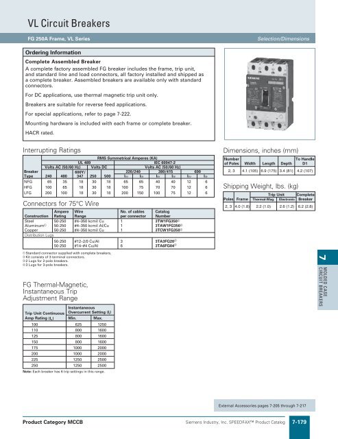
VL Circuit Breakers FG 250A Frame, VL Series Selection/Dimensions Ordering Information Complete Assembled Breaker A complete factory assembled FG breaker includes the frame, trip unit, and standard line and load connectors, all factory installed and shipped as a complete breaker. Assembled breakers are available only with standard connectors. For DC applications, use thermal magnetic trip unit only. Breakers are suitable for reverse feed applications. For special applications, refer to page 7-222. Mounting hardware is included with each frame or complete breaker. HACR rated. Interrupting Ratings To RMS Symmetrical Amperes (KA) 50-250 #14–#4 Cu/Al 6 3TA6FG04 UL 489 IEC 60947-2 Number of Poles Width Length Depth Handle D1 Volts AC (50/60 Hz) Volts DC Volts AC (50/60 Hz) Breaker 600Y/ 220/240 380/415 690 2, 3 4.1 (105) 6.9 (175) 3.4 (81) 4.2 (107) Type 240 480 347 250 500 ICU ICS ICU ICS ICU ICS NFG 65 35 18 30 18 65 65 40 40 12 6 HFG 100 65 18 30 18 100 75 70 70 12 6 Shipping Weight, lbs. (kg) LFG 200 100 18 30 18 200 150 100 75 12 6 Trip Unit Complete Connectors for 75°C Wire Poles Frame Thermal-Mag. Electronic Breaker 2, 3 4.0 (1.8) 2.2 (1.0) 2.6 (1.2) 6.2 (2.8) Ampere Wire No. of cables Catalog Construction Rating Range per connector Number Steel 50-250 #4–350 kcmil Cu 1 3TW1FG350 Aluminum 50-250 #4–350 kcmil Al/Cu 1 3TAW1FG350 Copper 50-250 #4–350 kcmil Cu 1 3TCW1FG350 Distribution Lugs 50-250 #12–2/0 Cu/Al 3 3TA3FG20 Standard connector supplied with complete breakers. Kit consists of 3 terminal connectors. 2 Lugs for 2-pole breakers. 3 Lugs for 3-pole breakers. FG Thermal-Magnetic, Instantaneous Trip Adjustment Range Instantaneous Trip Unit Continuous Overcurrent Setting (I i) Amp Rating (I n ) Min. Max. 100 625 1250 110 800 1600 125 800 1600 150 800 1600 175 1000 2000 200 1000 2000 225 1250 2500 250 1250 2500 Note: Each breaker has 6 trip settings in this range. Dimensions, inches (mm) 7 MOLDED CASE CIRCUIT BREAKERS External Accessories pages 7-205 through 7-217 Product Category MCCB Siemens Industry, Inc. SPEEDFAX Product Catalog 7-179
- Page 487 and 488: Molded Case Circuit Breakers Intern
- Page 489 and 490: Molded Case Circuit Breakers MD 800
- Page 491 and 492: Molded Case Circuit Breakers Intern
- Page 493 and 494: Molded Case Circuit Breakers ND 120
- Page 495 and 496: Molded Case Circuit Breakers Intern
- Page 497 and 498: Molded Case Circuit Breakers SPD 16
- Page 499 and 500: Molded Case Circuit Breakers RD 200
- Page 501 and 502: Molded Case Circuit Breakers Motor
- Page 503 and 504: Molded Case Circuit Breakers Adjust
- Page 505 and 506: Molded Case Circuit Breakers Adjust
- Page 507 and 508: Molded Case Circuit Breakers Digita
- Page 509 and 510: WL Power Circuit Breakers 3-pole &
- Page 511 and 512: WL Power Circuit Breakers Electroni
- Page 513 and 514: Lug Information Mechanical Lug Revi
- Page 515 and 516: Lug information Optional Mechanical
- Page 517 and 518: Molded Case Circuit Breakers Intern
- Page 519 and 520: Circuit Breakers Circuit Breaker Ac
- Page 521 and 522: Molded Case Circuit Breakers Extern
- Page 523 and 524: Molded Case Circuit Breakers Extern
- Page 525 and 526: Molded Case Circuit Breakers Extern
- Page 527 and 528: Molded Case Circuit Breakers Unusua
- Page 529 and 530: VL Circuit Breakers Catalog Numberi
- Page 531 and 532: VL Circuit Breakers Technical Overv
- Page 533 and 534: VL Circuit Breakers Trip Unit Overv
- Page 535 and 536: VL Circuit Breakers DG 150A Frame,
- Page 537: VL Circuit Breakers DG 150A Electro
- Page 541 and 542: VL Circuit Breakers FG 250A Electro
- Page 543 and 544: VL Circuit Breakers JG 400A Frame,
- Page 545 and 546: VL Circuit Breakers JG 400A Electro
- Page 547 and 548: VL Circuit Breakers LG 600A Frame,
- Page 549 and 550: VL Circuit Breakers LG 600A Electro
- Page 551 and 552: VL Circuit Breakers MG 800A Frame,
- Page 553 and 554: VL Circuit Breakers MG 800A Electro
- Page 555 and 556: VL Circuit Breakers NG 1200A Frame,
- Page 557 and 558: VL Circuit Breakers NG 1200A Electr
- Page 559 and 560: VL Circuit Breakers PG 1600A Frame,
- Page 561 and 562: VL Circuit Breakers Internal Access
- Page 563 and 564: VL Circuit Breakers Motor Circuit P
- Page 565 and 566: External Accessories Selection 7 MO
- Page 567 and 568: For MG Frame For NG to PG Frame 800
- Page 569 and 570: For MG Frame For NG Frame For PG Fr
- Page 571 and 572: Revised on 11/30/19 For JG to LG Fr
- Page 573 and 574: For JG Frame For LG Frame For MG Fr
- Page 575 and 576: Revised on 11/30/19 For JG Frame Fo
- Page 577 and 578: Revised on 11/30/19 For JG Frame F
- Page 579 and 580: VL Circuit Breakers Selection Suffi
- Page 581 and 582: Technical Data Revised on 05/31/18
- Page 583 and 584: Technical Data Unusual Operating Co
- Page 585 and 586: Molded Case Circuit Breakers Series
- Page 587 and 588: Molded Case Circuit Breakers Series
VL Circuit Breakers<br />
FG 250A Frame, VL Series<br />
Selection/Dimensions<br />
Ordering Information<br />
Complete Assembled Breaker<br />
A complete factory assembled FG breaker includes the frame, trip unit,<br />
and standard line and load connectors, all factory installed and shipped as<br />
a complete breaker. Assembled breakers are available only with standard<br />
connectors.<br />
For DC applications, use thermal magnetic trip unit only.<br />
Breakers are suitable for reverse feed applications.<br />
For special applications, refer to page 7-222.<br />
Mounting hardware is included with each frame or complete breaker.<br />
HACR rated.<br />
Interrupting Ratings<br />
To RMS Symmetrical Amperes (KA)<br />
50-250 #14–#4 Cu/Al 6 3TA6FG04 <br />
UL 489 IEC 60947-2<br />
Number<br />
of Poles Width Length Depth<br />
Handle<br />
D1<br />
Volts AC (50/60 Hz) Volts DC Volts AC (50/60 Hz)<br />
Breaker 600Y/ 220/240 380/415 690<br />
2, 3 4.1 (105) 6.9 (175) 3.4 (81) 4.2 (107)<br />
Type 240 480 347 250 500 ICU ICS ICU ICS ICU ICS<br />
NFG 65 35 18 30 18 65 65 40 40 12 6<br />
HFG 100 65 18 30 18 100 75 70 70 12 6 Shipping Weight, lbs. (kg)<br />
LFG 200 100 18 30 18 200 150 100 75 12 6<br />
Trip Unit Complete<br />
Connectors for 75°C Wire<br />
Poles Frame Thermal-Mag. Electronic Breaker<br />
2, 3 4.0 (1.8) 2.2 (1.0) 2.6 (1.2) 6.2 (2.8)<br />
Ampere Wire No. of cables Catalog<br />
Construction Rating Range per connector Number<br />
Steel 50-250 #4–350 kcmil Cu 1 3TW1FG350 <br />
Aluminum 50-250 #4–350 kcmil Al/Cu 1 3TAW1FG350 <br />
Copper 50-250 #4–350 kcmil Cu 1 3TCW1FG350 <br />
Distribution Lugs<br />
50-250 #12–2/0 Cu/Al 3 3TA3FG20 <br />
Standard connector supplied with complete breakers.<br />
Kit consists of 3 terminal connectors.<br />
2 Lugs for 2-pole breakers.<br />
3 Lugs for 3-pole breakers.<br />
FG Thermal-Magnetic,<br />
Instantaneous Trip<br />
Adjustment Range<br />
Instantaneous<br />
Trip Unit Continuous Overcurrent Setting (I i)<br />
Amp Rating (I n ) Min. Max.<br />
100 625 1250<br />
110 800 1600<br />
125 800 1600<br />
150 800 1600<br />
175 1000 2000<br />
200 1000 2000<br />
225 1250 2500<br />
250 1250 2500<br />
Note: Each breaker has 6 trip settings in this range.<br />
Dimensions, inches (mm)<br />
7<br />
MOLDED CASE<br />
CIRCUIT BREAKERS<br />
External Accessories pages 7-205 through 7-217<br />
Product Category MCCB<br />
Siemens Industry, Inc. SPEEDFAX Product Catalog 7-179


