Speedfax 2017
VL Circuit Breakers Technical Overview Technical Frame Summary and Ratings Table — Continued Frame Family LG MG NG PG 7 MOLDED CASE CIRCUIT BREAKERS Continuous Ampere Range 150 to 600A 200 to 800A 300 to 1200A 400 to 1600A Number of Poles 2, 3 2, 3 2, 3 3 Maximum Voltage Rating 600V 600V 600V 600V Type of Protection Thermal-Magnetic u u u u Electronic u u u u Electronic with LCD u u u u Motor Circuit Protector u u u — Molded Case Switch u u u u 100% Rated 400/500 Amp u u u Interchangeable Trip Unit — u u u W In.(mm) 5.5 (139) 7.5 (190) 9 (229) H 11 (279) 16 (406) 16 (406) D 4.2 (102) 4.7 (114) 6.2 (157) D1 5.4 (138) 5.9 (151) 8.1 (207) Type N – Normal Interrupting Rating a , RMS Symmetrical Amperes (kA) 240Vac 65 65 65 65 UL 480Vac 35 35 35 35 600Vac 18 25 25 25 240Vac 65/65 65/65 65/65 65/65 IEC 415Vac 45/45 50/50 50/25 50/25 (l CU /l CS ) 690Vac 12/6 20/10 20/10 20/10 DC Voltages – Interrupting Rating (kA) d 250Vdc - 2p 30 22 22 22 500Vdc - 3p c 25 35 35 35 Type H – High Interrupting Rating a , RMS Symmetrical Amperes (kA) 240Vac 100 100 100 100 UL 480Vac 65 65 65 65 600Vac 18 35 35 35 240Vac 100/75 100/75 100/75 100/50 IEC 415Vac 70/70 70/70 70/35 70/35 (l CU /l CS ) 690Vac 15/8 30/15 30/15 30/15 DC Voltages – Interrupting Rating (kA) d 250Vdc - 2p 30 25 25 25 500Vdc - 3p c 35 50 50 50 600Vdc - 3p e 65 65 65 65 Type L – Very High Interrupting Rating a , RMS Symmetrical Amperes (kA) 240Vac 200 200 200 200 UL 480Vac 100 100 100 100 600Vac 18 50 65 65 240Vac 200/150 200/150 200/150 200/150 IEC 415Vac 100/75 100/75 100/75 100/75 (l CU /l CS ) 690Vac 15/8 35/17 35/17 35/17 DC Voltages – Interrupting Rating (kA) d 250Vdc - 2p 30 42 42 42 500Vdc - 3p c 35 65 65 65 a UL does not recognize AIC ratings for Molded Case Switches or Motor Circuit Protectors. b 25kA available in a special version. Standard breakers rated 18kA. See page 7-188. c 500Vdc nominal, 600Vdc max. for ungrounded DC UPS systems. d DC Interruption Ratings do not apply to electronic trip circuit breakers. e For 600 VDC breakers see page 7-204. Thermal-magnetic available non-interchangeable only. 13.6” with extended shields. 7-172 Siemens Industry, Inc. SPEEDFAX Product Catalog
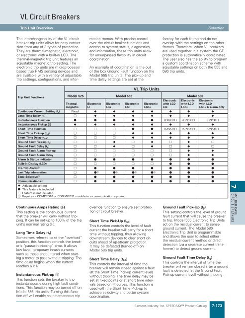
VL Circuit Breakers Trip Unit Overview Selection The interchangeability of the VL circuit breaker trip units allow for easy conversion from any of 3 types of protection. They are thermal-magnetic, electronic, or electronic with a built-in LCD. The thermal-magnetic trip unit features an adjustable magnetic trip setting. The electronic trip units are microprocessor based true RMS sensing devices and are available with a variety of adjustable trip settings, configurations, and information menus. With precise control over the circuit beaker functions and access to system status, diagnostics, and information, these trip units allow for unsurpassed flexibility in circuit coordination. An example of coordination is the out of the box Ground Fault function on the Model 555 trip units. The pick-up and time delay settings are set at the factory for each frame and do not overlap with the settings on the other frames. Therefore, when VL breakers are used together in a system the GF protection is automatically coordinated. The user also has the ability to program a custom coordination scheme with adjustable settings on both the 555 and 586 trip units. VL Trip Units Trip Unit Functions Continuous Amps Rating (I r ) This setting is the continuous current that the breaker will carry without tripping. It can be set up to 100% of the trip unit’s nominal rating (I n ). Long Time Delay (t r ) Sometimes referred to as the “overload” position, this function controls the breaker‘s “pause-in-tripping” time. It allows low level, temporary inrush currents such as those encountered when starting a motor to pass without tripping. The time delay begins when the current reaches 6 x I r . Instantaneous Pick-up (I i ) This function sets the breaker to trip instantaneously during high fault conditions. This function may be turned off on Model 586 trip units. Turning this function off will enable an instantaneous trip Model 525 Model 555 Model 586 Thermalmagnetic Electronic LI Electronic LIG Electronic LSI Electronic LSIG override function to ensure self protection of circuit breaker. Short Time Pick-Up (l sd ) This function controls the level of fault current the breaker will carry for a short time without tripping, thus allowing downstream devices to clear short circuits ahead of up-stream protection. It may be defeated (turned-off) on Model 586 trip units. Short Time Delay (t sd ) This controls the interval of time the breaker will remain closed against a fault (at the Short Time Pick-up current level) without tripping. The time delay may be set at fixed points or at short time intervals based on l 2 t curves. This function is used with the Short Time Pick-up to achieve selectivity and better system coordination. Electronic with LCD LSI Electronic with LCD LSIG Electronic with LCD LSI + G alarm only Continuous Current Setting (I r ) Fixed u u u u u u u Long Time Delay (t r ) h u u u u u u u Instantaneous Function l l l l l (ON/OFF) (ON/OFF) (ON/OFF) Instantaneous Pickup (I i ) u u u u u u u u Short Time Function h h h l l (ON/OFF) (ON/OFF) (ON/OFF) Short Time Pick-up (I sd ) h h h u u u u u Short Time Delay (t sd ) h h h u u u u u Ground Fault Pick-up (I g ) h h u h u h u h Ground Fault Delay (t g ) h h u h u h u h Ground Fault Alarm Pick-up h h h h h h u u Ground Fault Alarm Delay h h h h h h u u Alarm & Status Indicator h l l l l l l l Built-in Display (LCD) h h h h h l l l Pre-Trip Alarm a h l l l l l l l Last Trip Information h l a l a l a l a l l l Zone Selective a h l l l l l l l Communications a h l l l l l l l u Adjustable setting l This feature is included h Feature is not included. a Requires a COMPRO20 or COMMOD21 module in a communication system. Ground Fault Pick-Up (I g ) This setting controls the level of ground fault current that will cause the breaker to trip. Model 555 Electronic Trip Units act on the residual current to sense ground current. The Model 586 Electronic Trip Unit is programmable and allows the user to select either the residual current method or direct detection (via a separate current transformer) to detect ground current. Ground Fault Time Delay (t g ) This controls the interval of time the breaker will remain closed after a ground fault is detected (at the Ground Fault Pick-up current level) without tripping. 7 MOLDED CASE CIRCUIT BREAKERS Siemens Industry, Inc. SPEEDFAX Product Catalog 7-173
- Page 481 and 482: Molded Case Circuit Breakers LD 600
- Page 483 and 484: Molded Case Circuit Breakers SLD 60
- Page 485 and 486: Molded Case Circuit Breakers LMD 80
- Page 487 and 488: Molded Case Circuit Breakers Intern
- Page 489 and 490: Molded Case Circuit Breakers MD 800
- Page 491 and 492: Molded Case Circuit Breakers Intern
- Page 493 and 494: Molded Case Circuit Breakers ND 120
- Page 495 and 496: Molded Case Circuit Breakers Intern
- Page 497 and 498: Molded Case Circuit Breakers SPD 16
- Page 499 and 500: Molded Case Circuit Breakers RD 200
- Page 501 and 502: Molded Case Circuit Breakers Motor
- Page 503 and 504: Molded Case Circuit Breakers Adjust
- Page 505 and 506: Molded Case Circuit Breakers Adjust
- Page 507 and 508: Molded Case Circuit Breakers Digita
- Page 509 and 510: WL Power Circuit Breakers 3-pole &
- Page 511 and 512: WL Power Circuit Breakers Electroni
- Page 513 and 514: Lug Information Mechanical Lug Revi
- Page 515 and 516: Lug information Optional Mechanical
- Page 517 and 518: Molded Case Circuit Breakers Intern
- Page 519 and 520: Circuit Breakers Circuit Breaker Ac
- Page 521 and 522: Molded Case Circuit Breakers Extern
- Page 523 and 524: Molded Case Circuit Breakers Extern
- Page 525 and 526: Molded Case Circuit Breakers Extern
- Page 527 and 528: Molded Case Circuit Breakers Unusua
- Page 529 and 530: VL Circuit Breakers Catalog Numberi
- Page 531: VL Circuit Breakers Technical Overv
- Page 535 and 536: VL Circuit Breakers DG 150A Frame,
- Page 537 and 538: VL Circuit Breakers DG 150A Electro
- Page 539 and 540: VL Circuit Breakers FG 250A Frame,
- Page 541 and 542: VL Circuit Breakers FG 250A Electro
- Page 543 and 544: VL Circuit Breakers JG 400A Frame,
- Page 545 and 546: VL Circuit Breakers JG 400A Electro
- Page 547 and 548: VL Circuit Breakers LG 600A Frame,
- Page 549 and 550: VL Circuit Breakers LG 600A Electro
- Page 551 and 552: VL Circuit Breakers MG 800A Frame,
- Page 553 and 554: VL Circuit Breakers MG 800A Electro
- Page 555 and 556: VL Circuit Breakers NG 1200A Frame,
- Page 557 and 558: VL Circuit Breakers NG 1200A Electr
- Page 559 and 560: VL Circuit Breakers PG 1600A Frame,
- Page 561 and 562: VL Circuit Breakers Internal Access
- Page 563 and 564: VL Circuit Breakers Motor Circuit P
- Page 565 and 566: External Accessories Selection 7 MO
- Page 567 and 568: For MG Frame For NG to PG Frame 800
- Page 569 and 570: For MG Frame For NG Frame For PG Fr
- Page 571 and 572: Revised on 11/30/19 For JG to LG Fr
- Page 573 and 574: For JG Frame For LG Frame For MG Fr
- Page 575 and 576: Revised on 11/30/19 For JG Frame Fo
- Page 577 and 578: Revised on 11/30/19 For JG Frame F
- Page 579 and 580: VL Circuit Breakers Selection Suffi
- Page 581 and 582: Technical Data Revised on 05/31/18
VL Circuit Breakers<br />
Trip Unit Overview<br />
Selection<br />
The interchangeability of the VL circuit<br />
breaker trip units allow for easy conversion<br />
from any of 3 types of protection.<br />
They are thermal-magnetic, electronic,<br />
or electronic with a built-in LCD. The<br />
thermal-magnetic trip unit features an<br />
adjustable magnetic trip setting. The<br />
electronic trip units are microprocessor<br />
based true RMS sensing devices and<br />
are available with a variety of adjustable<br />
trip settings, configurations, and information<br />
menus. With precise control<br />
over the circuit beaker functions and<br />
access to system status, diagnostics,<br />
and information, these trip units allow<br />
for unsurpassed flexibility in circuit<br />
coordination.<br />
An example of coordination is the out<br />
of the box Ground Fault function on the<br />
Model 555 trip units. The pick-up and<br />
time delay settings are set at the<br />
factory for each frame and do not<br />
overlap with the settings on the other<br />
frames. Therefore, when VL breakers<br />
are used together in a system the GF<br />
protection is automatically coordinated.<br />
The user also has the ability to program<br />
a custom coordination scheme with<br />
adjustable settings on both the 555 and<br />
586 trip units.<br />
VL Trip Units<br />
Trip Unit Functions<br />
Continuous Amps Rating (I r )<br />
This setting is the continuous current<br />
that the breaker will carry without tripping.<br />
It can be set up to 100% of the trip<br />
unit’s nominal rating (I n ).<br />
Long Time Delay (t r )<br />
Sometimes referred to as the “overload”<br />
position, this function controls the breaker‘s<br />
“pause-in-tripping” time. It allows<br />
low level, temporary inrush currents<br />
such as those encountered when starting<br />
a motor to pass without tripping. The<br />
time delay begins when the current<br />
reaches 6 x I r .<br />
Instantaneous Pick-up (I i )<br />
This function sets the breaker to trip<br />
instantaneously during high fault conditions.<br />
This function may be turned off on<br />
Model 586 trip units. Turning this function<br />
off will enable an instantaneous trip<br />
Model 525 Model 555 Model 586<br />
Thermalmagnetic<br />
Electronic<br />
LI<br />
Electronic<br />
LIG<br />
Electronic<br />
LSI<br />
Electronic<br />
LSIG<br />
override function to ensure self protection<br />
of circuit breaker.<br />
Short Time Pick-Up (l sd )<br />
This function controls the level of fault<br />
current the breaker will carry for a short<br />
time without tripping, thus allowing<br />
downstream devices to clear short circuits<br />
ahead of up-stream protection.<br />
It may be defeated (turned-off) on<br />
Model 586 trip units.<br />
Short Time Delay (t sd )<br />
This controls the interval of time the<br />
breaker will remain closed against a fault<br />
(at the Short Time Pick-up current level)<br />
without tripping. The time delay may be<br />
set at fixed points or at short time intervals<br />
based on l 2 t curves. This function is<br />
used with the Short Time Pick-up to<br />
achieve selectivity and better system<br />
coordination.<br />
Electronic<br />
with LCD<br />
LSI<br />
Electronic<br />
with LCD<br />
LSIG<br />
Electronic<br />
with LCD<br />
LSI + G alarm only<br />
Continuous Current Setting (I r ) Fixed u u u u u u u<br />
Long Time Delay (t r ) h u u u u u u u<br />
Instantaneous Function l l l l l (ON/OFF) (ON/OFF) (ON/OFF)<br />
Instantaneous Pickup (I i ) u u u u u u u u<br />
Short Time Function h h h l l (ON/OFF) (ON/OFF) (ON/OFF)<br />
Short Time Pick-up (I sd ) h h h u u u u u<br />
Short Time Delay (t sd ) h h h u u u u u<br />
Ground Fault Pick-up (I g ) h h u h u h u h<br />
Ground Fault Delay (t g ) h h u h u h u h<br />
Ground Fault Alarm Pick-up h h h h h h u u<br />
Ground Fault Alarm Delay h h h h h h u u<br />
Alarm & Status Indicator h l l l l l l l<br />
Built-in Display (LCD) h h h h h l l l<br />
Pre-Trip Alarm a h l l l l l l l<br />
Last Trip Information h l a l a l a l a l l l<br />
Zone Selective a h l l l l l l l<br />
Communications a h l l l l l l l<br />
u Adjustable setting<br />
l This feature is included<br />
h Feature is not included.<br />
a Requires a COMPRO20 or COMMOD21 module in a communication system.<br />
Ground Fault Pick-Up (I g )<br />
This setting controls the level of ground<br />
fault current that will cause the breaker<br />
to trip. Model 555 Electronic Trip Units<br />
act on the residual current to sense<br />
ground current. The Model 586<br />
Electronic Trip Unit is programmable<br />
and allows the user to select either<br />
the residual current method or direct<br />
detection (via a separate current transformer)<br />
to detect ground current.<br />
Ground Fault Time Delay (t g )<br />
This controls the interval of time the<br />
breaker will remain closed after a ground<br />
fault is detected (at the Ground Fault<br />
Pick-up current level) without tripping.<br />
7<br />
MOLDED CASE<br />
CIRCUIT BREAKERS<br />
Siemens Industry, Inc. SPEEDFAX Product Catalog 7-173


