

Looking through walls - Coatings on glass for ... - W. Theiss Hard
Looking through walls - Coatings on glass for ... - W. Theiss Hard
Looking through walls - Coatings on glass for ... - W. Theiss Hard

Create successful ePaper yourself
Turn your PDF publications into a flip-book with our unique Google optimized e-Paper software.
<str<strong>on</strong>g>Looking</str<strong>on</strong>g> <str<strong>on</strong>g>through</str<strong>on</strong>g> <str<strong>on</strong>g>walls</str<strong>on</strong>g> - <str<strong>on</strong>g>Coatings</str<strong>on</strong>g> <strong>on</strong> <strong>glass</strong> <strong>for</strong> buildings<br />
by Wolfgang <strong>Theiss</strong><br />
M. <strong>Theiss</strong> – <strong>Hard</strong>- and Software <strong>for</strong> Optical Spectroscopy, Dr.-Bernhard-<br />
Klein-Str. 110, D-52078 Aachen, Germany<br />
Abstract<br />
Modern buildings are equipped with windows having thermal insulating<br />
properties like solid <str<strong>on</strong>g>walls</str<strong>on</strong>g>. Advanced thin film coatings not <strong>on</strong>ly efficiently<br />
suppress the emissi<strong>on</strong> of heat radiati<strong>on</strong> but provide a large variety of possible<br />
colors <strong>for</strong> architectural design. Optical spectroscopy from the ultraviolet to the<br />
infrared plays an important role in the development of these products. The<br />
relati<strong>on</strong> between depositi<strong>on</strong> c<strong>on</strong>diti<strong>on</strong>s and optical properties of the produced<br />
materials is studied, and the interacti<strong>on</strong> of the individual layers with their<br />
neighbours in the stack is investigated. The optical design of optimized<br />
multilayers and spectroscopic producti<strong>on</strong> c<strong>on</strong>trol is discussed.<br />
Moderne Gebäude sind mit Fenstern ausgestattet, die thermisch so gut<br />
isolieren wie massive Wände. Die dabei eingesetzten Dünnschichtsysteme<br />
unterdrücken effizient die Wärmeabstrahlung des Glases und geben<br />
gleichzeitig dem Architekten eine grosse Gestaltungsmöglichkeit bezüglich der<br />
Farbe der Verglasung. Optische Spektroskopie vom ultravioletten bis zum<br />
infraroten Spektralbereich spielt eine große Rolle bei der Entwicklung dieser<br />
Produkte. Der Zusammenhang zwischen den Depositi<strong>on</strong>sbedingungen und den<br />
erzielten optischen Eigenschaften der produzierten Materialien sowie die<br />
Wechselwirkung der einzelnen Schichten mit ihren Nachbarn im<br />
Schichtsystem werden untersucht. Das optische Design der<br />
Vielfachschichtsysteme und die spektroskopische Produkti<strong>on</strong>sk<strong>on</strong>trolle werden<br />
diskutiert.<br />
Introducti<strong>on</strong><br />
The way we build houses and large buildings has changed dramatically during the last<br />
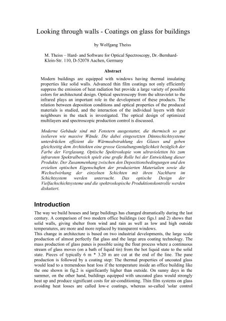
century. A comparis<strong>on</strong> of two modern office buildings (see figs.1 and 2) shows that<br />
solid <str<strong>on</strong>g>walls</str<strong>on</strong>g>, giving shelter from wind and rain as well as low and high outside<br />
temperatures, are more and more replaced by transparent windows.<br />
This change in architecture is based <strong>on</strong> two industrial developments, the large scale<br />
producti<strong>on</strong> of almost perfectly flat <strong>glass</strong> and the large area coating technology. The<br />
mass producti<strong>on</strong> of <strong>glass</strong> panes is possible using the float process where a c<strong>on</strong>tinuous<br />
stream of <strong>glass</strong> moves (<strong>on</strong> a bath of liquid tin) from the hot liquid state to the solid<br />
state. Pieces of typically 6 m * 3.20 m are cut at the end of the line. The pane<br />
producti<strong>on</strong> is followed by a coating step: The thermal properties of uncoated <strong>glass</strong><br />
would lead to a tremendous heat loss if the temperature inside an office building like<br />
the <strong>on</strong>e shown in fig.2 is significantly higher than outside. On sunny days in the<br />
summer, <strong>on</strong> the other hand, buildings equipped with uncoated <strong>glass</strong> would str<strong>on</strong>gly<br />
heat up and produce significant costs <strong>for</strong> air-c<strong>on</strong>diti<strong>on</strong>ing. Thin film systems <strong>on</strong> <strong>glass</strong><br />
avoiding heat losses are called low-e coatings, whereas so-called 'solar c<strong>on</strong>trol
coatings' avoid to some extent<br />
the building's heating up by<br />
sunlight. The functi<strong>on</strong> of both<br />
coating types is discussed in the<br />
next secti<strong>on</strong>s.<br />
The cost-effective producti<strong>on</strong> of<br />
large area coatings is a<br />
permanent struggle <strong>for</strong><br />
homogeneity: The depositi<strong>on</strong> of<br />
layers with thickness variati<strong>on</strong>s<br />
of less than 1 nm <strong>on</strong> a 6 m * 3.20<br />
m substrate would be difficult<br />
enough [1]. Un<strong>for</strong>tunately, this<br />
problem is doubled by the fact<br />
that the sputtering devices must<br />
be operated in a way causing their characteristics to drift away in time. The secti<strong>on</strong><br />
about thin films deposited by<br />
large area coaters addresses<br />
the problems related to this<br />
depositi<strong>on</strong> technique. In<br />
additi<strong>on</strong>, the interacti<strong>on</strong> of<br />
adjacent layers during and<br />
after the depositi<strong>on</strong> is<br />
discussed.<br />
The design of new coating<br />
products must take into<br />
account the wanted target<br />
properties of the coating, the<br />
available range of optical<br />
c<strong>on</strong>stants and film<br />
thicknesses in the producti<strong>on</strong><br />
line, possible homogeneity<br />
problems and costs.<br />
The last secti<strong>on</strong> is about the<br />
optical inspecti<strong>on</strong> of the<br />
Fig. 2 A large modern office building in the year 2004<br />
producti<strong>on</strong> which is an<br />
important tool to c<strong>on</strong>trol the<br />
depositi<strong>on</strong>. In<strong>for</strong>mati<strong>on</strong> about<br />
thicknesses and optical c<strong>on</strong>stants of the layers produced at present is used to take<br />
appropriate depositi<strong>on</strong> c<strong>on</strong>trol acti<strong>on</strong>s to obtain wanted and stable coating properties.<br />
All computati<strong>on</strong>s shown in this article have been d<strong>on</strong>e with the CODE software [2].<br />
Low emissi<strong>on</strong> coatings<br />
Fig. 1 A large modern (700 years ago) office building<br />
Replacing a solid wall by a piece of <strong>glass</strong> does not <strong>on</strong>ly increase the <str<strong>on</strong>g>through</str<strong>on</strong>g>put of<br />
light but also that of heat. The transfer of heat <str<strong>on</strong>g>through</str<strong>on</strong>g> a wall is usually specified by<br />
the so-called U-value (overall coefficient of heat transmissi<strong>on</strong>) [3]. This quantity gives<br />
the transmitted power per wall area and temperature difference between the inside and<br />
the outside of the building. The usual unit is W/(m 2 K).<br />
A 23 cm thick wall of simple brick st<strong>on</strong>e has a U-value of 2.2 W/(m 2 K) which means<br />
that there is a power stream of 22 W <str<strong>on</strong>g>through</str<strong>on</strong>g> each square meter if the inside-outside
temperature difference is 10°C. Cavities and additi<strong>on</strong>al heat insulati<strong>on</strong> (e.g. by foams)<br />
can reduce the U-value of a wall to 0.5 W/(m 2 K) or less.<br />
An uncoated <strong>glass</strong> pane has a U-value of about 6 W/(m 2 K) which is 10 times higher<br />
than that of a typical wall. Windows with single glazing can easily reach temperatures<br />
below 0°C in cold winter nights. While this may lead to beautiful ice sculptures<br />
growing in the kitchen there is a str<strong>on</strong>g demand to decrease the U-value and avoid<br />
energy streaming out of the window.<br />
The easiest way to block the heat c<strong>on</strong>ducti<strong>on</strong> <str<strong>on</strong>g>through</str<strong>on</strong>g> the <strong>glass</strong> is to introduce an air<br />
gap (typical thickness: 10 ... 20 mm) between two <strong>glass</strong> panes: Windows with double<br />
glazing have reduced U-values of about 2.7 W/(m 2 K). The remaining heat transfer<br />
mechanisms in double glazings are heat c<strong>on</strong>vecti<strong>on</strong> <str<strong>on</strong>g>through</str<strong>on</strong>g> the air gap and the<br />
trransfer of energy by infrared radiati<strong>on</strong>. The c<strong>on</strong>vecti<strong>on</strong> losses can be reduced<br />
replacing the air by 'heavy' filling gases (Ar is standard today, Kr and Xe would be<br />
better but are more expensive). However, the U-value is lowered <strong>on</strong>ly by about 0.1 ...<br />
0.2 this way.<br />
In order to<br />
understand the<br />
energy transfer by<br />
infrared radiati<strong>on</strong><br />
we have to<br />
investigate the<br />
properties of float<br />
<strong>glass</strong> <strong>for</strong><br />
wavelengths above<br />
5000 nm (far<br />
infrared). Here the<br />
transmissi<strong>on</strong> of a<br />
typical 4 mm pane<br />
is zero, and the<br />
reflectance is a few<br />
percent <strong>on</strong>ly (see<br />
fig.3). This means<br />
that <strong>glass</strong> is almost completely 'black' <strong>for</strong> mid and far infrared light. A material that<br />
absorbs most of the incident radiati<strong>on</strong> is, <strong>on</strong> the other hand, also a very efficient<br />
U-value<br />
3.0<br />
2.8<br />
2.6<br />
2.4<br />
2.2<br />
2.0<br />
1.8<br />
1.6<br />
1.4<br />
1.2<br />
1.0<br />
R / T / Intensity [a.u.]<br />
100<br />
80<br />
60<br />
40<br />
20<br />
0<br />
Blackbody radiati<strong>on</strong> and float <strong>glass</strong> properties<br />
Transmittance<br />
Reflectance<br />
300 K<br />
290 K<br />
5000 10000 15000 20000<br />
Wavelength [nm]<br />
Fig. 3 Transmittance and reflectance of a 4 mm float <strong>glass</strong> from the UV to<br />
the far infrared. In additi<strong>on</strong>, the spectral distributi<strong>on</strong> of blackbody radiati<strong>on</strong><br />
emitted at 290 and 300 K is shown <strong>for</strong> comparis<strong>on</strong>.<br />
U-value vs. Ag thickness<br />
Outside<br />
Inside<br />
Vacuum<br />
Float A<br />
4.000 mm<br />
Arg<strong>on</strong><br />
16.000 mm<br />
Ag<br />
12.0 nm<br />
Float A<br />
4.000 mm<br />
Vacuum<br />
0 5 10 15 20 25 30 35 40<br />
Ag thickness [nm]<br />
Fig. 4 U-value of a double glazing with a silver coating <strong>on</strong> the<br />
interior pane to suppress infrared emissi<strong>on</strong>. The window has a<br />
16 mm Arg<strong>on</strong> filling.<br />
emitter of radiati<strong>on</strong>. Hence a<br />
<strong>glass</strong> pane acts as an almost<br />
perfect blackbody radiator.<br />
In a double glazing window<br />
<strong>on</strong>e has two efficient infrared<br />
light sources and absorbers<br />
opposite to each other. If<br />
there is a temperature<br />
difference between the<br />
interior of the building and<br />
the outside, a quite large net<br />
flow of radiative energy from<br />
the warm side to the cold<br />
occurs. Fig. 3 shows the<br />
spectral distributi<strong>on</strong>s of<br />
blackbody radiati<strong>on</strong> emitted
at 290 and 300 K.<br />
In order to suppress the<br />
radiati<strong>on</strong> exchange it would<br />
be nice to be able to switch<br />
off the 'warm' light source.<br />
This can be achieved by the<br />
depositi<strong>on</strong> of a metallic layer<br />
<strong>on</strong> the pane mounted <strong>on</strong> the<br />
interior side of the building.<br />
The layer increases the<br />
reflectance, decreases the<br />
absorpti<strong>on</strong> and this way<br />
diminishes the emissi<strong>on</strong> of<br />
infrared radiati<strong>on</strong>. Silver<br />
turned out to be the best<br />
material <strong>for</strong> this purpose. Fig.<br />
4 shows the str<strong>on</strong>g effect of the silver thickness <strong>on</strong> the U-value. U-values significantly<br />
below 1.0 W/(m 2 K) cannot be achieved with double glazings. With triple glazings<br />
values of 0.6 W/(m 2 K) are possible.<br />
However, the positive improvement of the heat insulati<strong>on</strong> is accompanied by the<br />
unwanted side effect of severely decreasing transmittance in the visible (Fig. 5).<br />
Fortunately, surrounding the silver layer by two dielectric layers (oxides in most<br />
cases) of appropriate<br />
Transmittance<br />
1.0<br />
0.8<br />
0.6<br />
0.4<br />
0.2<br />
0.0<br />
thickness and refractive<br />
index <strong>on</strong>e can almost<br />
completely restore the<br />
transmittance of the<br />
uncoated <strong>glass</strong> while the<br />
suppressi<strong>on</strong> of the infrared<br />
emissi<strong>on</strong> remains<br />
unchanged. Thin film<br />
systems like this are<br />
called low-e (<strong>for</strong> 'low<br />
emissi<strong>on</strong>') coatings (see<br />
fig. 6).<br />
The oxide layers of low-e<br />
coatings can be used to<br />
vary the color of the<br />
window. Selecting different types of oxides and different thicknesses <strong>for</strong> the<br />
individual layers <strong>on</strong>e can adjust the visual appearance of a building to the architect's<br />
ideas (see fig. 7).<br />
Solar c<strong>on</strong>trol coatings<br />
1.0<br />
0.8<br />
0.6<br />
0.4<br />
0.2<br />
0.0<br />
400<br />
450<br />
500<br />
550<br />
Wavelength<br />
[nm]<br />
600<br />
650<br />
700<br />
750<br />
Transmittance<br />
0 5 10<br />
0.0<br />
15 20 25 30 35 40<br />
Ag thickness<br />
[nm]<br />
Fig. 5 Dependence of the transmittance of a double glazing<br />
(layer structure as in fig.4 ) <strong>on</strong> the silver thickness.<br />
Uncoated double glazing<br />
10 nm silver coating<br />
Low-E coating<br />
400 450 500 550 600 650 700 750<br />
Wavelength [nm]<br />
Fig. 6 Transmittance spectra of an uncoated double glazing, a<br />
double glazing with a 10 nm silver layer <strong>on</strong> the interior pane, and a<br />
typical low-e coating (also with 10 nm silver)<br />
If a large fracti<strong>on</strong> of a building fassade is made of <strong>glass</strong> a lot of sunlight is transmitted<br />
into the building. Most of it will be absorbed inside and significantly heat up the<br />
rooms <strong>on</strong> sunny days. This can cause high air-c<strong>on</strong>diti<strong>on</strong>ing costs. Whereas the<br />
transmissi<strong>on</strong> of light in the visible cannot be avoided (that's the purpose of the<br />
window!) the large fracti<strong>on</strong> of infrared light in the solar radiati<strong>on</strong> arriving at a<br />
building (shown in fig. 8) is unwanted and can be blocked by so-called 'solar c<strong>on</strong>trol'<br />
coatings.<br />
1.0<br />
0.8<br />
0.6<br />
0.4<br />
0.2
Transmittance / Intensity<br />
Fig. 7 Color variati<strong>on</strong> of low-e coatings with the same U-value of 1.2 W/(m^2 K)<br />
1.0<br />
0.8<br />
0.6<br />
0.4<br />
0.2<br />
0.0<br />
500 1000 1500 2000 2500<br />
Wavelength [nm]<br />
Fig. 8 Transmissi<strong>on</strong> spectra of double glazing windows without coating, with low-e and solar c<strong>on</strong>trol<br />
coatings. The intensity distributi<strong>on</strong> of incident solar radiati<strong>on</strong> (the so-called AM 1.5 radiati<strong>on</strong><br />
distributi<strong>on</strong> is taken from [3]) is shown as well.<br />
Fig. 8 shows a comparis<strong>on</strong> of the transmittance spectra of typical low-e and solar<br />
c<strong>on</strong>trol coatings. The latter is much more 'selective', i.e. there is a sharp decrease of<br />
the transmissi<strong>on</strong> from the visible to the infrared. This ideally step-like feature cannot<br />
be obtained with a single silver layer. In most cases, two silver layers being embedded<br />
in and separated by oxide layers are applied to achieve high selectivity. Solar c<strong>on</strong>trol<br />
coatings are deposited <strong>on</strong> the inner side of the exterior pane in double glazing<br />
windows. Their per<strong>for</strong>mance is expressed in two quantities: The 'Light transmittance'<br />
(average transmittance in the visible, weighted with our eyes' sensitivity) [5] indicates<br />
how well we can look <str<strong>on</strong>g>through</str<strong>on</strong>g> the window. The 'Total solar energy transmittance' g<br />
[5] gives the overall <str<strong>on</strong>g>through</str<strong>on</strong>g>put of solar radiati<strong>on</strong>, including the direct solar<br />
transmittance and sec<strong>on</strong>dary energy streams by absorpti<strong>on</strong> and re-emissi<strong>on</strong>. A good<br />
solar c<strong>on</strong>trol coating has a high light transmittance and a low g-value. A ratio of 2<br />
between the two quantities is c<strong>on</strong>sidered to be almost ideal.<br />
<<br />
><br />
Uncoated double glazing<br />
Low-E coating<br />
Solar c<strong>on</strong>trol coating<br />
AM 1.5 radiati<strong>on</strong><br />
<<br />
>
Thin films produced by large area coaters<br />
The layer stacks discussed above must be deposited <strong>on</strong> large <strong>glass</strong> panes with a very<br />
high degree of homogeneity and at reas<strong>on</strong>able costs. At present the producti<strong>on</strong> scheme<br />
sketched in fig.9 is the method of choice [6]. The uncoated panes are moved into a<br />
large evacuated volume. Linear sputtering devices (usually operated with Ar gas)<br />
Uncoated <strong>glass</strong><br />
Pumps<br />
Fig. 9 Principle of a large area coating line <strong>for</strong> the producti<strong>on</strong> of a solar c<strong>on</strong>trol coating<br />
optimized <strong>for</strong> homogeneity perpendicular to the moti<strong>on</strong> of the <strong>glass</strong> deposit metals or<br />
(with additi<strong>on</strong>al reactive gas inlets) oxides or nitrides. Depending <strong>on</strong> the speed of the<br />
substrates, the required layer thickness and the available sputtering rates several<br />
cathodes are grouped together to produce <strong>on</strong>e of the coating's functi<strong>on</strong>al layers.<br />
To maintain the vacuum and to properly separate the 'oxide areas' from the 'metal<br />
areas' a tremendous pumping equipment is required. The sputtering devices c<strong>on</strong>sume a<br />
lot of electrical power, too.<br />
Hence the goal is to finish<br />
as many panes as possible<br />
without interrupti<strong>on</strong> –<br />
typically every minute a<br />
coated pane leaves the<br />
coater. If everything works<br />
fine about 25000 m 2 <strong>glass</strong><br />
can be coated <strong>on</strong> <strong>on</strong>e day.<br />
However, reactive<br />
sputtering of oxides is a<br />
stable process <strong>on</strong>ly in the<br />
so-called oxidic mode<br />
where the partial pressure<br />
of oxygen is very high.<br />
Un<strong>for</strong>tunately, in this mode<br />
the depositi<strong>on</strong> rates are<br />
very low (see fig. 10).<br />
Large area coating line<br />
Sputtering device Vacuum Coated <strong>glass</strong><br />
Bottom Oxide Metal Center Oxide Metal Top Oxide<br />
Depositi<strong>on</strong> rate [a.u.]<br />
1.4<br />
1.2<br />
1.0<br />
0.8<br />
0.6<br />
0.4<br />
0.2<br />
0.0<br />
Metallic mode<br />
Transiti<strong>on</strong> area<br />
Oxidic mode<br />
0 2 4 6 8 10<br />
Oxygen flow [a.u.]<br />
Fig. 10 Typical relati<strong>on</strong> between the sputtering rate and the<br />
applied oxygen flow. In the transiti<strong>on</strong> area the depositi<strong>on</strong> rate <strong>for</strong> a<br />
given flow depends <strong>on</strong> the history of the process (hysteresis<br />
behaviour).<br />
Ec<strong>on</strong>omic coating depositi<strong>on</strong> is <strong>on</strong>ly possible in the transiti<strong>on</strong> area where the<br />
stabilizati<strong>on</strong> of the sputtering process is very difficult [7]. This problem and the slow<br />
drift of the sputtering characteristics due to erosi<strong>on</strong> of the targets (due to the loss of<br />
material which is used <strong>for</strong> the depositi<strong>on</strong>) make it necessary to c<strong>on</strong>stantly watch and<br />
regulate the process.
For the proper design of coatings it is very important to investigate the dependence of<br />
the obtained optical c<strong>on</strong>stants <strong>on</strong> the depositi<strong>on</strong> c<strong>on</strong>diti<strong>on</strong>s, e.g. the applied electrical<br />
power and oxygen (or nitrogen) pressure. The best way to do this is to produce single<br />
layers of all relevant materials and analyze optical spectra (like reflectance and<br />
transmittance) to determine the complex refractive index n + i k of the sputtered<br />
materials. With appropriate adjustable dispersi<strong>on</strong> models (like the OJL model <strong>for</strong><br />
amorphous materials [8]) <strong>on</strong>e can describe the optical properties of all materials used<br />
in <strong>glass</strong> coatings with a few key parameters (see fig.11). The relati<strong>on</strong> of these<br />
parameters to the depositi<strong>on</strong> c<strong>on</strong>diti<strong>on</strong>s gives an excellent basis <strong>for</strong> coating design and<br />
producti<strong>on</strong> c<strong>on</strong>trol. This increased knowledge justifies to use the expensive<br />
producti<strong>on</strong> line <strong>for</strong> several hours to produce single layers under various producti<strong>on</strong><br />
c<strong>on</strong>diti<strong>on</strong>s.<br />
2.0<br />
1.5<br />
1.0<br />
0.5<br />
0.0<br />
Air<br />
Oxide<br />
100.9 nm<br />
Float <strong>glass</strong><br />
4.000 mm<br />
Air<br />
20000.0000<br />
Bandgap [1/cm]<br />
31463.4570 50000.0000<br />
Thickness [nm]<br />
100.9<br />
Refractive index Oxide analysis (single layer)<br />
0.0000<br />
C<strong>on</strong>stant<br />
3.1439 5.0000<br />
500 1000 1500 2000 2500<br />
Wavelength [nm]<br />
R (coating side)<br />
500 1000 1500 2000 2500<br />
Wavelength [nm]<br />
Fig. 11 Analysis of three measured spectra (the red spectra <strong>on</strong> the right) by fitting a dispersi<strong>on</strong> model<br />
and the thickness of an amorphous oxide layer <strong>on</strong> <strong>glass</strong>. The simulated spectra are drawn blue. The<br />
graph of the obtained refractive index model (left side) shows the real part n in blue and the imaginary<br />
part k in red.<br />
Knowing single layer properties is not sufficient to describe spectra of complex<br />
coating products with high quality. Layers in a layer stack can have different<br />
properties than single layers <strong>on</strong> <strong>glass</strong>. The growth of a thin film depends <strong>on</strong> the type,<br />
temperature and roughness of the underlying material. In additi<strong>on</strong>, high rate sputtering<br />
is not a very gentle method, and the depositi<strong>on</strong> of a layer may influence (damage) the<br />
films underneath. Slow diffusi<strong>on</strong> processes may lead to changes of the coatings even a<br />
l<strong>on</strong>g time after finishing the depositi<strong>on</strong>.<br />
The silver layers which are very important <strong>for</strong> the functi<strong>on</strong> of low-e and solar c<strong>on</strong>trol<br />
coatings are very sensitive to their neighbourhood in the layer stack. The high<br />
reflectance of thin silver films depends critically <strong>on</strong> the mobility of the electr<strong>on</strong>s.<br />
Their free moti<strong>on</strong> can be disturbed by impurities and defects in the bulk, but also by<br />
surface roughness. In a metallic film of a few nanometers thickness there are frequent<br />
boundary collisi<strong>on</strong>s of the electr<strong>on</strong>s – smooth interfaces lead to mirror-like reflecti<strong>on</strong>s<br />
of the electr<strong>on</strong> waves with no decrease of the mobility whereas rough surfaces cause<br />
diffuse electr<strong>on</strong> scattering with significant c<strong>on</strong>sequences <strong>for</strong> the c<strong>on</strong>ductivity. The<br />
damping c<strong>on</strong>stant of the simple Drude model <strong>for</strong> the electr<strong>on</strong>s [9] in silver is a good<br />
parameter to characterize the quality of the layer – fig.12 shows the influence of the<br />
Modified Transmittance<br />
Modified Reflectance<br />
Modified Reflectance<br />
40<br />
35<br />
30<br />
25<br />
20<br />
15<br />
10<br />
5<br />
0<br />
100<br />
90<br />
80<br />
70<br />
60<br />
50<br />
40<br />
30<br />
20<br />
10<br />
0<br />
40<br />
35<br />
30<br />
25<br />
20<br />
15<br />
10<br />
5<br />
0<br />
T<br />
500 1000 1500 2000 2500<br />
Wavelength [nm]<br />
R (<strong>glass</strong> side)<br />
500 1000 1500 2000 2500<br />
Wavelength [nm]
silver quality <strong>on</strong> the U-value of the final product (low-e coating).<br />
Achieving and maintaining a good silver c<strong>on</strong>ductivity can be very important in order<br />
to place a coating product <strong>on</strong> the market. In order to reach this goal, <strong>on</strong>e has to do<br />
extra work <strong>on</strong> both sides of the silver layer. Underneath surface roughness is reduced<br />
U-value<br />
U-value vs. electr<strong>on</strong> damping<br />
1.50<br />
1.45<br />
1.40<br />
1.35<br />
1.30<br />
1.25<br />
1.20<br />
1.15<br />
1.10<br />
1.05<br />
1.00<br />
200 300 400 500 600 700 800 900 1000<br />
Damping c<strong>on</strong>stant [1/cm]<br />
Fig. 12 Relati<strong>on</strong> of the U-value of a low-e coating to the damping c<strong>on</strong>stant of the electr<strong>on</strong>s in the<br />
silver layer (Drude model). For sputtered layers, typical values <strong>for</strong> the damping c<strong>on</strong>stants are 300 to<br />
500 1/cm. 'High quality silver' can have damping c<strong>on</strong>stants as low as 140 1/cm.<br />
by the depositi<strong>on</strong> of thin oxide layers specialized to build very smooth interfaces [10].<br />
On top of the silver an additi<strong>on</strong>al blocker layer is produced which protects the silver<br />
from subsequent sputtering damage and diffusi<strong>on</strong> of oxygen atoms. In some cases, the<br />
final coating is mechanically protected by an extra-hard nitride topping. This way lowe<br />
coatings which have in principle the structure oxide / silver /oxide can easily be<br />
composed of 6 to 8 thin films.<br />
Window coating design<br />
Outside<br />
Inside<br />
Vacuum<br />
Float A<br />
4.000 mm<br />
Arg<strong>on</strong><br />
16.000 mm<br />
B-oxide<br />
56.3 nm<br />
Ag<br />
10.1 nm<br />
C-oxide<br />
23.5 nm<br />
Float A<br />
4.000 mm<br />
Vacuum<br />
The design of new coating products should be based <strong>on</strong> the knowledge about<br />
achieveable n and k values, interacti<strong>on</strong>s of neighboured layers and established<br />
depositi<strong>on</strong> rates. The quantitative analysis and descripti<strong>on</strong> of single layer samples and<br />
already existing coating products (see fig. 13) can be used to build up a database of<br />
optical c<strong>on</strong>stants and partial layer stacks. This can be used as a source of successful<br />
building blocks <strong>for</strong> new combinati<strong>on</strong>s.<br />
Since the operati<strong>on</strong> of large area coating lines is very expensive <strong>on</strong>e can save a lot of<br />
m<strong>on</strong>ey if the predicti<strong>on</strong> of the optical properties of new products is reliable. Ideally<br />
the parameters of the model should reflect the parameters of the producti<strong>on</strong> devices<br />
such as electrical power or oxygen pressure. The design software should enable easy<br />
selecti<strong>on</strong> and variati<strong>on</strong> of these parameters with instant display of the results, i.e.<br />
optical spectra and characterizing quantities such as color coordinates, light<br />
transmittance and U- or g-values. In additi<strong>on</strong>, it should be easy to inspect how<br />
producti<strong>on</strong> tolerances (e.g. pressure fluctuati<strong>on</strong>s) show up in the properties of a<br />
coating.<br />
After manual parameter variati<strong>on</strong>s and visual inspecti<strong>on</strong> <strong>on</strong>e would like to switch to<br />
automated design. Target spectra or wanted values <strong>for</strong> colors or other technical data
are used as optimizati<strong>on</strong> goals. Usually several parameters related to the thicknesses<br />
and optical c<strong>on</strong>stants of the model are adjusted simultaneously. For parameter fine-<br />
Reflectance<br />
Transmittance<br />
1.00<br />
0.80<br />
0.60<br />
0.40<br />
0.20<br />
0.00<br />
1.0<br />
0.8<br />
0.6<br />
0.4<br />
0.2<br />
0.0<br />
Solar c<strong>on</strong>trol coating: Quantitative modelling<br />
R<br />
500 1000 1500 2000 2500<br />
Wavelength [nm]<br />
T<br />
500 1000 1500 2000 2500<br />
Wavelength [nm]<br />
1.00<br />
0.80<br />
0.60<br />
0.40<br />
0.20<br />
0.00<br />
Fig. 13 Example <strong>for</strong> successful quantitative modelling of a solar c<strong>on</strong>trol coating with 14 layers. The<br />
measured (red) reflectance from the coating side (R), the transmissi<strong>on</strong> (T) and the reflectance with<br />
backside illuminati<strong>on</strong> are reproduced very well by the model (simulated spectra in blue). There are no<br />
measured data <strong>for</strong> the fr<strong>on</strong>tside reflectance at an angle of incidence of 70°.<br />
tuning <strong>on</strong>e can use optimizati<strong>on</strong> methods that move from the starting design to the<br />
next local minimum of the deviati<strong>on</strong> to the target values. This is a matter of sec<strong>on</strong>ds<br />
or minutes and can be mixed with manual user interacti<strong>on</strong>s. Methods that search <strong>for</strong><br />
the global deviati<strong>on</strong> minimum are much slower and should not require any user<br />
acti<strong>on</strong>s in order to be applied in overnight optimizati<strong>on</strong> runs.<br />
Optical producti<strong>on</strong> c<strong>on</strong>trol<br />
Reflectance<br />
Reflectance<br />
1.0<br />
0.8<br />
0.6<br />
0.4<br />
0.2<br />
0.0<br />
As discussed above, thin film depositi<strong>on</strong> in large area coating lines must be permantly<br />
observed and corrected. Due to the high operati<strong>on</strong>al costs, <strong>on</strong>e must detect deviati<strong>on</strong>s<br />
from the target properties of the coating as early as possible.<br />
Fig. 14 shows the principle of an optical producti<strong>on</strong> c<strong>on</strong>trol system [6]. At every<br />
important positi<strong>on</strong> al<strong>on</strong>g the producti<strong>on</strong> line appropriate optical measurements are<br />
d<strong>on</strong>e. An 'optical network' is resp<strong>on</strong>sible <strong>for</strong> the coordinati<strong>on</strong> of the data acquisiti<strong>on</strong><br />
and analysis of the measured data. It provides status in<strong>for</strong>mati<strong>on</strong> about the present<br />
c<strong>on</strong>diti<strong>on</strong> of the producti<strong>on</strong> line. The operator can use this in<strong>for</strong>mati<strong>on</strong> in order to<br />
decide if producti<strong>on</strong> parameters should be changed and which acti<strong>on</strong>s are required.<br />
It would be advantageous to record several spectra at each positi<strong>on</strong>: Reflectance from<br />
the coating and the <strong>glass</strong> side as well as transmittance, if possible in a large spectral<br />
range. These spectra would provide enough in<strong>for</strong>mati<strong>on</strong> to safely determine the<br />
thickness and the optical c<strong>on</strong>stants of each main layer of the coating. Ideally <strong>on</strong>e<br />
would like to measure at several spots (at least 3) perpendicular to the directi<strong>on</strong> of the<br />
<strong>glass</strong> moti<strong>on</strong> in order to check the lateral homogeneity of the depositi<strong>on</strong>.<br />
There are some limitati<strong>on</strong>s, however. Recording 3 spectra at 5 positi<strong>on</strong>s al<strong>on</strong>g the<br />
producti<strong>on</strong> line with 3 spots perpendicular to the line would mean to buy, install and<br />
operate 45 spectrometers. Even if low-cost array spectrometers are used, this is just<br />
too expensive at the moment. Also the analysis and the handling of the obtained data<br />
R back<br />
500 1000 1500 2000 2500<br />
Wavelength [nm]<br />
R, 70 deg<br />
500 1000 1500 2000 2500<br />
Wavelength [nm]<br />
Vacuum<br />
Material 1<br />
5.0 nm<br />
Material 7<br />
21.4 nm<br />
Material 6<br />
3.0 nm<br />
Material 4<br />
10.9 nm<br />
Material 5<br />
1.2 nm<br />
Material 3<br />
4.4 nm<br />
Material 2<br />
8.4 nm<br />
Material 1<br />
10.0 nm<br />
Material 7<br />
35.4 nm<br />
Material 6<br />
3.0 nm<br />
Material 4<br />
12.2 nm<br />
Material 5<br />
1.2 nm<br />
Material 3<br />
4.4 nm<br />
Material 2<br />
13.8 nm<br />
Float<br />
7.900 mm<br />
Vacuum
would require several computers and a sophisticated software which would also be<br />
expensive.<br />
A good current compromise is to record transmittance spectra in the coating line,<br />
Uncoated <strong>glass</strong><br />
Pumps<br />
Fig. 14 Scheme of an optical producti<strong>on</strong> c<strong>on</strong>trol system. After the depositi<strong>on</strong> of each functi<strong>on</strong>al layer<br />
optical measurements are taken (vertical yellow bars). The 'Optical inspecti<strong>on</strong> network' is resp<strong>on</strong>sible<br />
<strong>for</strong> proper coordinati<strong>on</strong> and analysis of the measurements and delivers an overview of the present<br />
depositi<strong>on</strong> results.<br />
<strong>on</strong>ly in the center of the panes. The final product is inspected outside the vacuum<br />
chamber with a moving system of 2 or 3 spectrometers (R, T, eventually R from the<br />
backside) which record spectra at several spots perpendicular to the <strong>glass</strong> moti<strong>on</strong> (see<br />
fig. 15). This way about 10<br />
spectrometers are required.<br />
Another restricti<strong>on</strong> c<strong>on</strong>cerns the<br />
available spectral range. Since<br />
there is not too much time <strong>for</strong><br />
spectrum recording, array<br />
detectors have to be used. These<br />
are available at low cost (USD<br />
2000 ... 4000) <strong>on</strong>ly in the<br />
Vis/NIR range up to 1100 nm<br />
wavelength (since they use<br />
silic<strong>on</strong> detectors). Infrared array<br />
detectors which extend the range<br />
up to 1700 nm or 2200 nm<br />
wavelength are about a factor 10<br />
more expensive (USD 20000)<br />
and up to now not widely used<br />
<strong>for</strong> <strong>on</strong>line depositi<strong>on</strong> c<strong>on</strong>trol.<br />
With increasing complexity of<br />
the coatings optical<br />
Large area coating line<br />
Sputtering device Vacuum Coated <strong>glass</strong><br />
Bottom Oxide Metal Center Oxide Metal Top Oxide<br />
Optical inspecti<strong>on</strong> network<br />
Fig. 15 Possible spectrometer positi<strong>on</strong>s <strong>for</strong> producti<strong>on</strong><br />
c<strong>on</strong>trol:<br />
Left: Measurements <strong>on</strong>ly at the center of the depositi<strong>on</strong><br />
Center: Measurements at several fixed positi<strong>on</strong>s<br />
Right: Moving spectrometer system<br />
measurements providing in<strong>for</strong>mati<strong>on</strong> about the individual parts of the depositi<strong>on</strong> line<br />
will become more and more important. Not <strong>on</strong>ly because in<strong>for</strong>mati<strong>on</strong> about individual<br />
layers cannot be extracted from the final coating properties any more if the number of<br />
layers is too large, but also because small depositi<strong>on</strong> errors in the beginning of the<br />
producti<strong>on</strong> line can eventually be compensated by proper parameter changes at
subsequent depositi<strong>on</strong> steps.<br />
Summary and outlook<br />
Progress in <strong>glass</strong> coating technology has enabled architects to replace solid <str<strong>on</strong>g>walls</str<strong>on</strong>g> by<br />
transparent <strong>glass</strong>. Complex large area coating lines produce very homogeneous thin<br />
film systems with tailored optical and thermal properties at low costs. Optical<br />
spectroscopy is used in research and producti<strong>on</strong> c<strong>on</strong>trol to determine layer thicknesses<br />
and optical c<strong>on</strong>stants.<br />
Currently under development are switchable optical properties (electrochromic or<br />
gasochromic) and the integrati<strong>on</strong> of large area displays and thin film solar cells into<br />
<strong>glass</strong> fassades.<br />
References<br />
[1] M.Geisler et al., Proc. 4 th ICCG (2002), p. 59 , C.P. Klages, H. Gläser, M.A.<br />
Aegerter (eds.)<br />
[2] CODE – a thin film analysis and design program developed and distributed by<br />
M.<strong>Theiss</strong> <strong>Hard</strong>- and Software (www.mtheiss.com/wcd.htm)<br />
[3] European standard EN 673<br />
[4] S.R. Wenham , M.A. Green and M.E. Watt, , "Applied Photovoltaics",<br />
Appendix B, (Bridge Printery, Sydney, 1994).<br />
[5] European standard EN 410<br />
[6] M. List et al., Proc. 5 th ICCG (2004), p. 401, J. Puetz, A. Kurz, M.A. Aegerter<br />
(eds.)<br />
[7] S.J. Nadel et al., Proc. 4 th ICCG (2002), p. 53 , C.P. Klages, H. Gläser, M.A.<br />
Aegerter (eds.)<br />
[8] S.K.O'Leary, S.R.Johns<strong>on</strong>, P.K.Lim, J.Appl. Phys. Vol. 82, No. 7 (1997), p.<br />
3334-3340<br />
[9] P.Drude, Ann. Phys. 3 (1900), p. 369<br />
[10] O. Treichel et al., Proc. 4 th ICCG (2002), p. 675, C.P. Klages, H. Gläser, M.A.<br />
Aegerter (eds.)
