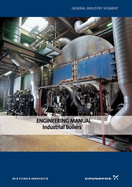
ENGINEERING MANUAL Industrial Boilers - INSCO Group
ENGINEERING MANUAL Industrial Boilers - INSCO Group
ENGINEERING MANUAL Industrial Boilers - INSCO Group
You also want an ePaper? Increase the reach of your titles
YUMPU automatically turns print PDFs into web optimized ePapers that Google loves.
<strong>ENGINEERING</strong> <strong>MANUAL</strong><br />
<strong>Industrial</strong> <strong>Boilers</strong><br />
General Industry seGment
Ver 01. 18/12/2008<br />
General. .............................................................................................................................................................. 2<br />
Boiler types.................................................................................................................................................... 2<br />
Boiler system ................................................................................................................................................ 4<br />
Boiler components. ......................................................................................................................................... 4<br />
Deaerators/Condenser. ............................................................................................................................. 4<br />
Economizer.................................................................................................................................................... 6<br />
Economizer in the marine. ................................................................................................................... 6<br />
Economizers in landbased boilers...................................................................................................... 7<br />
Boiler pumps................................................................................................................................................. 7<br />
Boiler feed................................................................................................................................................. 7<br />
Condensat pump ..................................................................................................................................11<br />
Shunt pump............................................................................................................................................12<br />
What Grundfos offers..............................................................................................................................14<br />
Pumps and sizing...........................................................................................................................................20<br />
Sizing.............................................................................................................................................................20<br />
Page 1 of 25
General.<br />
Ver 01. 18/12/2008<br />
The production of steam and hot water is one of the world’s largest industries. Grundfos is<br />
pleased to be the preferred supplier of pumps for boiler systems for these industries.<br />
Grundfos pumps are reliable, efficient and cover a vide performance range. As an<br />
experienced consultant in the implementation of boiler systems, we engage in a process of<br />
close partnership and dialogue to find the best solution for your system.<br />
Grundfos is a global enterprise with a worldwide service network. When you need export or<br />
need on-the-spot advice in a particular part of the world, we have the technical expertise<br />
close by.<br />
Boiler types.<br />
There are three main types of boilers:<br />
• Hot water boiler<br />
• Thermal oil boiler<br />
• Steam boiler<br />
The demands and the sizing of the pumps used for these boiler types are very different.<br />
Page 2 of 25
Ver 01. 18/12/2008<br />
1. Hot water boiler<br />
Hot water boilers are normally used in room and process heating. This kind of system is<br />
suitable for discharge temperatures up to 140°C. The advantage of hot water over steam is<br />
that energy loss is lower than with steam boilers.<br />
Hot water<br />
boiler<br />
Burne<br />
2. Thermal oil boiler<br />
In hot oil boilers is used oil in stead of steam or water. The advantage with oil is that the<br />
system does not have to be pressurised above 100°C as with water and steam, but functions<br />
in atmospheric pressures of up to 300°C. In contrast, water requires a pressure of 85 bar to<br />
avoid evaporating. The construction of thermal oil boilers and systems is almost identical to<br />
that of hot water boilers.<br />
Hot Oil<br />
boiler<br />
Burne<br />
Shunt<br />
Shunt<br />
Forward<br />
Return<br />
Forward<br />
Return<br />
3. Steam boiler<br />
Steam is normally used in industrial process heating due to its high energy content. Steam is<br />
also used for cleaning applications and turbine-generation. The advantage of steam over hot<br />
water is its high energy content and ability to release energy during condensation. This also<br />
allows for very small heat exchangers.<br />
End<br />
End<br />
Page 3 of 25
Boiler system<br />
Return condensate<br />
Boiler components.<br />
From water treatment<br />
Deaerators/Condenser.<br />
Deaerator<br />
Level sensor<br />
Condensate pumps<br />
Condensate tank Feed pumps<br />
Ver 01. 18/12/2008<br />
Level sensor<br />
Steam boiler<br />
Deaerator and condenser tanks are only used in steam boiler systems and not in hot water<br />
and hot oil boil because here the fluid always is on liquid form. The construction of these<br />
two types of tanks is almost identical, but as their names suggest, they are used for different<br />
purposes.<br />
Two primary principles are used with this form of tank design: thermal and vacuum. Which<br />
one depends on which type of boiler being used. Each principle also has different pump<br />
construction requirements.<br />
Thermo principle<br />
A tank using the thermal principle is connected to the atmosphere. This design is normally<br />
used in smaller plants. Here, steam is used to maintain tank water temperature at around<br />
105°C, which removes air from the water.<br />
Vacuum principle<br />
Here, an ejector pump is used to create a vacuum in the tank. This causes the tank water to<br />
start boiling because of the low temperature, which in turn removes air from the water. This<br />
principle is normally used for steam turbine applications.<br />
Page 4 of 25
Ver 01. 18/12/2008<br />
Deaerator.<br />
A deaerator is used to reduce oxygen (O 2 ) and carbonic acid (CO 2 ) levels in boiler feedwater<br />
to protect a boiler against corrosion. It is possible to reduce oxygen and carbonic acid levels<br />
to about < 0.02 mg/l of O 2 and 0 mg/l of CO 2, depending on deaerator construction.<br />
Condenser.<br />
A condenser ensures that all steam is condensed before being pumped back into the<br />
deaerator and on into the boiler. New treated water is normally fed into the condenser.<br />
Page 5 of 25
Economizer<br />
Ver 01. 18/12/2008<br />
Historically, economisers have only been used in large-scale power plants. However, the<br />
demand for more efficient boilers within industry and marine means that economisers are<br />
now far more commonplace.<br />
An economiser is a heat exchanger that is placed in the exhaust from a boiler or in the<br />
exhaust funnel of the main engine of a ship.<br />
Pump requirements differ greatly, depending on where the economiser is installed.<br />
Economizer in the marine.<br />
Referring to the diagram below, the circulation pump has to be sized to the pressure and<br />
temperature in the boiler, which can easily be 20 bar and 170°C. Because of this,<br />
economisers featuring air-cooled top and bearing flange may be required. The pump does<br />
not normally need to be capable of delivering a high differential pressure, as it only has to<br />
overcome the pressure loss in the plate heat exchanger (economiser).<br />
Condensat<br />
Deaerator<br />
Feed<br />
Boile<br />
Burne<br />
Stea<br />
Circulation<br />
Smoke to chimney<br />
Economize<br />
Smoke from main engine<br />
Page 6 of 25
Ver 01. 18/12/2008<br />
Economizers in landbased boilers.<br />
An economiser used with a boiler located on land uses the boiler’s waste gases. The water<br />
circulated over the economiser is normally supplied by the main feed pump, but can also be<br />
fitted with its own circulation pump. The chimney will also include a bypass to allow waste<br />
gases to pass around the heat exchanger.<br />
The construction differs from marine design as the waste gases released from the main<br />
engine of a ship is significantly greater. Energy produced by marine applications often allow<br />
for the generation of overheated steam fed directly from economiser and out in the piping.<br />
Condensate<br />
Boiler pumps.<br />
A range of pumps for different boiler applications exist. This section describes typical<br />
positioning of the different pumps and how they are controlled.<br />
The most common boiler applications are boiler feed, condensate pumping, economiser<br />
circulation and shunt pumps.<br />
Sub system pumps such as dosing and water treatment pumps also exist.<br />
Boiler feed.<br />
Deareat<br />
Feed pump<br />
Smoke to chimney<br />
Smoke from boiler<br />
When we talk boiler feed there is normally 4 ways to do it.<br />
• On/off control<br />
• Via feed valve<br />
• Via feed valve and variable speed<br />
• Variable speed<br />
They will all be described underneath here.<br />
Boiler<br />
Burner<br />
Steam<br />
Page 7 of 25
1. On/off control<br />
Deaerator<br />
Ver 01. 18/12/2008<br />
Function<br />
In on/off control the feed pump is switched on/off via a level sensor or a differential<br />
pressure sensor. When the water level falls to the “Pump on” level, the pump starts<br />
pumping a large quantity of relatively cold water into the boiler. This will reduce the<br />
quantity of steam and cause the steam pressure to fall.<br />
This is the reason why on/off control causes variations in steam production. It may also<br />
cause over-boiling in the boiler, which may cause water to enter into the system.<br />
Benefits<br />
> Inexpensive<br />
> Simple to install<br />
> No bypass<br />
2. Via feed valve.<br />
Deaerator<br />
Bypass<br />
Feed pumps<br />
Feed pumps<br />
Steam boiler<br />
Steam boiler<br />
Level sensor<br />
Level sensor<br />
Function<br />
In this type of system the water level in the boiler is controlled by a feed valve, which is<br />
controlled by a level sensor or a differential pressure transmitter positioned on the boiler.<br />
The feed valve controls the water intake, which is adjusted according to steam<br />
consumption. This, however, requires that the feed pump is set to continuous operation.<br />
This system operates smoothly and is ideal for all types of steam boilers, both small and<br />
large, and will minimise the risk of over-boiling.<br />
Benefits<br />
> Boiler feeding adjusted according to<br />
steam consumption, as described.<br />
Page 8 of 25
Drawbacks<br />
> The pump must be set to<br />
continuous operation (energy consumption)<br />
> Bypass<br />
> Feed valve is expensive<br />
> Pressure loss across feed valve<br />
Ver 01. 18/12/2008<br />
Important<br />
Remember to size bypass according to the CR data as to min. flow. It may be an idea to stop<br />
the pump at closed valve. This requires, however, a signal from the valve.<br />
3. Via feed valve (variable speed)<br />
Deaerator<br />
Bypass<br />
Feed pumps<br />
Steam boiler<br />
Function<br />
In this system the water level in the boiler is controlled by a feed valve, which is controlled<br />
by a level sensor or a differential pressure transmitter positioned on the boiler. The feed<br />
valve controls the water intake, which is adjusted according to steam consumption. This,<br />
however, requires that the feed pump is set to continuous operation. This system operates<br />
smoothly and is ideal for all types of steam boilers, both small and large, and will minimise<br />
the risk of over-boiling.<br />
Benefits<br />
> Boiler feeding adjusted according to steam consumption.<br />
> Energy savings on pump operation.<br />
> Constant differential pressure across feed valve<br />
Drawbacks<br />
> Bypass<br />
> Feed valve is expensive<br />
> Pressure loss across feed valve<br />
Level sensor<br />
Important<br />
Requirements vary from one country to another as to the sizing of boiler feed pumps.<br />
Remember to size bypass according to the CR/CV data as to min. flow.<br />
It may be an idea to stop the pump at closed valve. This requires, however, a signal from the<br />
valve.<br />
Find out whether variable speed control of both pumps is required, as this increases<br />
expenses, but does not provide the same flexibility as to alternating pump operation.<br />
Due to poor inlet pressure the CR(N) Low NPSH may be a fine solution.<br />
Page 9 of 25
Accessories required<br />
Possibly Control 2000, pressure transmitter.<br />
4. Without feed valve<br />
Deaerator<br />
Feed pumps<br />
Ver 01. 18/12/2008<br />
Function<br />
In this system the water level in the boiler is controlled directly by the variable speed pumps<br />
without using a feed valve. The pumps are controlled by a level sensor or a differential<br />
pressure transmitter positioned on the boiler. This way the water intake is controlled<br />
according to steam consumption. This system operates smoothly and is ideal for all types of<br />
steam boilers, both small and large, and will minimise the risk of over-boiling.<br />
Benefits<br />
> As described, boiler feeding adjusted<br />
according to steam consumption<br />
> Energy savings on pump operation<br />
> No pressure loss across feed valve<br />
> Money earned equal to the price of an<br />
expensive feed valve<br />
Drawback<br />
> Requires precise and qualified start-up.<br />
Important<br />
A non-return valve must be installed on the suction pipe of the boiler.<br />
A minimum frequency must be defined ensuring that the pump can always overcome the<br />
pressure in the boiler. It must be ensured that the pump stops when steam consumption is<br />
zero.<br />
Accessories required<br />
Possibly Hydro MPC.<br />
Steam boiler<br />
Level sensor<br />
Page 10 of 25
Condensat pump<br />
1. Condensate pumping on/off<br />
Ver 01. 18/12/2008<br />
Function<br />
The pumps must move the feed water from the condensate tank to the deaerator. This<br />
system is typically on/off-controlled via a level sensor positioned in the deaerator.<br />
Benefits<br />
Inexpensive and simple to install<br />
Important<br />
Requirements vary from one country to another as to the sizing of condensate pumps (two<br />
pumps must always back up each other 100 %, requirements as to over-sizing, etc).<br />
As the distance to the deaerator is typically only between 2-5 m, the pump must have the<br />
smallest head possible.<br />
The pump is typically located right next to the condensate tank. The water temperature can<br />
be up to 95°C, and, therefore, cavitation may cause problems in this type of system.<br />
Consequently, a customised CR Low NPSH is a fine choice.<br />
Accessories required<br />
Dosing pumps and water treatment system.<br />
Page 11 of 25
Ver 01. 18/12/2008<br />
Shunt pump.<br />
The demands to a shunt pump are normally high flow and very low head. Because of that<br />
the shunt pump is normally maid with a 4 pol or 6 pol motor to get head down. Shunt<br />
pumps is normally single stage pumps.<br />
1. On/off shunt pump<br />
Function<br />
The shunt pump must ensure that the return temperature to the boiler is not getting too<br />
low. If the differential temperature is high it will stress the boiler. The pump must be sized<br />
according to the lowest return temperature, meaning that it is over-sized most of the time.<br />
Benefits<br />
> Inexpensive and simple to install<br />
> Safe operation (few components)<br />
Important<br />
Information about the right return-pipe temperature to be obtained from the boiler<br />
manufacturer.<br />
2. Variable shunt pump<br />
Function<br />
The pump must ensure that the return temperature to the boiler is not getting too low. If<br />
the differential temperature is high it will stress the boiler. A variable speed pump may be<br />
the right choice for this type of pump application. The pump must be installed with a<br />
temperature sensor registering the return temperature to the boiler, thereby ensuring a<br />
constant temperature.<br />
Benefits<br />
> Always constant return temperature<br />
> Energy savings<br />
Page 12 of 25
Important<br />
Information about the right return temperature to be obtained from the boiler<br />
manufacturer.<br />
Accessories required<br />
Temperature sensor, R100.<br />
Ver 01. 18/12/2008<br />
Page 13 of 25
What Grundfos offers.<br />
Ver 01. 18/12/2008<br />
1. E pump solutions.<br />
With Grundfos E-solution it is possible to optimise the feed pumps with the software. The<br />
reason you want to do that can be because the pump curve is labile. See the curve below to<br />
see how the curve looks and what problems it can give.<br />
As you can see on the curve it is possible to have 2 different flows on the same set point. Put<br />
another way, normal regulation of the pump is required on one part of the curve, i.e. greater<br />
flow and more speed, while on the other, inverse regulation is needed, i.e. less flow and<br />
more speed. A normal regulator is not capable of controlling both and will become very<br />
unstable, which can lead to poor steam quality.<br />
Grundfos e-solutions can be upgraded to address this type of problem, by increasing the<br />
frequency to 55 Hz and increasing the motor slip. The motor automatically adjusts when it<br />
falls under the labile point of the curve. See the chart below.<br />
Page 14 of 25
•Pump Curve is now continuously decreasing<br />
•Labile part of the curve is eliminated<br />
•Regulating Loop can work as expected.<br />
Ver 01. 18/12/2008<br />
The labile curve is not a problem in all boiler plants. Normally it is or can bee a problem if the<br />
feed pumps is placed close to the boiler, with a little friction loss as a result. Because of this<br />
you normally never see the problem in the marine ore other places where the pumps and<br />
boiler are placed far away from each other.<br />
Page 15 of 25
Ver 01. 18/12/2008<br />
2. NPSH<br />
To improve the NPSH curves on the CR pump range you can make the pump with an<br />
oversized inlet chamber. See the picture below, you can also see the result of a low NPSH<br />
impeller and what affect it has on the NPSH value.<br />
Page 16 of 25
Ver 01. 18/12/2008<br />
3. Air cooled top<br />
The air cooled top solution is used when you have water temperatures above 120 °C and up<br />
till 180°C. For oil it is up to 240°C.<br />
The air-cooled top separates the seal chamber<br />
from the pump by an air cooled chamber,<br />
generating an insulating effect similar to that of a<br />
thermos.<br />
Via a narrow passage between the pump and the<br />
air-cooled top, a small quantity of the pumped<br />
liquid insure that the seal chamber always is filled<br />
with liquid.<br />
Page 17 of 25
Ver 01. 18/12/2008<br />
4. Double shaft seal / Mag-Drive<br />
The double shaft seal or Mag-Drive is used where ingress of air through the shaft seal may<br />
occur. This phenomenon can occur when a set of duty standby pumps pump water from a<br />
vacuum tank, which can lead to air ingress into the pump when in standby. As the diagram<br />
below illustrates, this can be addressed by transferring some of the water from the<br />
pressurised side of the non-return valves back into the chamber between the double shaft<br />
seals.<br />
Vacuum Deareator or<br />
condensat tank<br />
Duty standby<br />
feed pump.<br />
Return pips to the<br />
double shaft seal<br />
chamber.<br />
Illustration of a pump top with double shaft seal arrangement.<br />
In stead of the pump with a double shaft seal arrangement, , one with a magnetically-driven<br />
shaft can also be used.<br />
See more in the Grundfos catalogue Custom built pumps.<br />
Page 18 of 25
Ver 01. 18/12/2008<br />
5. Bearing flange<br />
If inlet pressure is high, as with an economiser pump in a marine boiler installation, you may<br />
need to consider fitting a bearing flange.<br />
A bearing flange is an additional flange with an oversize ball bearing to absorb axial forces<br />
in both directions. The coupling part of the flange ensures optimum alignment.<br />
Page 19 of 25
Pumps and sizing.<br />
Before sizing your pumps, the following three factors need to be considered:<br />
Ver 01. 18/12/2008<br />
Cavitation.<br />
When you in the Deaerator ore condensate tank has water with a high temperature it is<br />
difficult to pump without the pump will cavitat. The higher the liquid , the more likely<br />
cavitation is to occur. This is because you in the first impeller have to “pull” in the water and<br />
as a result the pressure will fall a little bit and the water will start to evaporate. When the<br />
pressure is rising through the impeller and the small steam bobbles is starting to implode<br />
and become water again it’s called cavitation.<br />
Because of this problem the Deaerator/condensate tank is often placed several meters<br />
above the pump inlet to ensure a high as possible inlet pressure. And the pump is made<br />
with a special first stage design that reduces the pump’s NPSH value. See more under sizing<br />
of pumps.<br />
Shaft seal or Mag-Drive.<br />
For feed pumps pumping from a vacuum tank, there is a risk of air infiltration to the pump<br />
through the shaft seal. This phenomenon occurs when two feed pumps are running in<br />
parallel as duty standby pumps. Here, there is a risk that the standby pump may let air<br />
through the shaft seal due to the vacuum in the deaerator/condensate tank. This problem<br />
can be addressed by installing pumps with a double shaft seal arrangement with barrier<br />
water or a Mag-Drive pump. Read more about our custom-built pumps in the Grundfos<br />
catalogue.<br />
Sizing.<br />
In the European union there is a norm EN 12952-7 there has to be used in the sizing of the<br />
pumps. But you always have to check what the factors are in your country.<br />
Flow safety factor according to EN 12952-7<br />
The feed pump capacity shall correspond at least to 1,25 times the allowable steam output<br />
of all steam boilers. For safety reasons 1,15 times of maximum continuous rating is enough.<br />
For availability and difference in service conditions a greater margin can be necessary.<br />
Where boiler waters is constantly blown down in volumes exceeding 5 % of the allowable<br />
steam output, the feed pump capacity shall be increased by the corresponding percentage<br />
e.g., if the blow down is 8 % of the allowable steam output, the feed pump capacity shall be<br />
increased by 8%.<br />
Pressure safety factor according to EN 12952-7<br />
The feed pump shall be capable of supplying to the steam boiler both the feedwater<br />
quantities at maximum allowable pressure as specified above and the feedwater quantity<br />
corresponding to the allowable steam output 1,1 times the allowable working pressure.<br />
In some country’s your allowed to reduce the 10 % if the security valve has a certain size.<br />
Check local rules.<br />
Page 20 of 25
Ver 01. 18/12/2008<br />
Besides the rules above you cant just read the flow and pressure on the nameplate off the<br />
boiler, and use this data to size the pump. This is because of the high temperature on the<br />
water and hereby the lover density of the pumped water. See the example below.<br />
Be aware that pumps in boiler applications is not a part of the Pressure equipment directive<br />
97/23/EC (PED) according to guideline 1/11.<br />
Example for calculating flow and head.<br />
From the boiler nameplate we have the following information’s.<br />
Q Boiler = 20 tons/hour<br />
P Boiler max = 12,5 bar<br />
P Boiler drift = 10 bar<br />
Temp. = 175° C<br />
Condensate<br />
Deareator<br />
105°C<br />
Feed pump<br />
Boilerer<br />
Burner<br />
As you can see on the sketch above the 175°C mentioned on the nameplate is the<br />
temperature on the steam in the outlet from the boiler. So this you cant use to anything<br />
because the pump never sees it. When sizing you must always use the temperature in the<br />
deaerator.<br />
From the vapour table we have following data on water with a<br />
temp. on 105°C.<br />
Density (rho)= 955,2 kg/m3<br />
vapour pressure = 1,1668 bar<br />
Steam<br />
20 ton/hour<br />
175°C<br />
Page 21 of 25
Ver 01. 18/12/2008<br />
First we must calculate the data from the nameplate to some m 3 /h and some mVs that we<br />
can use in the sizing.<br />
Q<br />
h<br />
h<br />
Boiler<br />
Boiler<br />
Drift<br />
Q<br />
=<br />
ρ<br />
Boiler<br />
=<br />
pBoiler<br />
= =<br />
ρ ⋅ g<br />
pBoiler<br />
= =<br />
ρ ⋅ g<br />
⋅10<br />
955,<br />
2<br />
3<br />
20 3<br />
12,<br />
5<br />
955,<br />
2<br />
10 ⋅<br />
955,<br />
2<br />
= 20,<br />
9m<br />
/ h<br />
5<br />
⋅10<br />
= 133,<br />
4mVs<br />
⋅ 9,<br />
81<br />
10<br />
⋅<br />
5<br />
9,<br />
81<br />
= 106,<br />
7mVs<br />
When we then use the safety factors from EN 12952-7 we get the flow and head as belove.<br />
Q Pump max<br />
= 1,25 x QBoiler =1,25 x 22,4 = 26,1 m3/h<br />
Q Pump continuous = 1,15 x Qboiler = 1,15 x 22,4 = 25,8 m3/h<br />
hPump = 1,1 x hboiler = 1,1 x 133,4 = 146,7 mVs<br />
Page 22 of 25
Ver 01. 18/12/2008<br />
All values are now calculated so we can start to choose the pump. Be aware that the pumps<br />
don’t have to do both the flow and pressure at the same time. But as showed belove.<br />
Situation 1.: Flow 26,1 m 3 /h at 133,4 mVs<br />
Situation 2.: Head 146,7 mVs at 20,9 m 3 /h<br />
From these situations we choose the following pump because the pump is capable of doing<br />
both situations.<br />
Page 23 of 25
Ver 01. 18/12/2008<br />
Now we have 2 pumps that can do the job, but before we order we have to do a calculation<br />
on the NPSH value.<br />
To avoid cavitation in the pump, NPSH system > NPSH pump<br />
NPSH system = h b – h f – h v ± h geo – h s<br />
NPSH system = Is the pressure available on the inlet of the pump.<br />
h b = Atmospheric pressure at the pump site.<br />
h f = Friction loss in the suction pipe.<br />
h v = Vapour pressure of the liquid.<br />
h geo = Vapour pressure of the liquid.<br />
h s = Safety factor. Normally varies between 0,5 and 1 m.<br />
Example: With the value from earlier and the tank placed 5 m above the pumps we will get<br />
the following formula.<br />
p p<br />
hsystem = − h f − − hgeo<br />
− hs<br />
=<br />
ρ ⋅ g ρ ⋅ g<br />
1,<br />
25<br />
953,<br />
7<br />
5<br />
⋅10<br />
− 2 −<br />
⋅ 9,<br />
81<br />
1,<br />
25<br />
953,<br />
7<br />
5<br />
⋅10<br />
+ 5 −1<br />
= 2,<br />
0mVs<br />
⋅ 9,<br />
81<br />
As written earlier it is the density on 105°C water we are using because it is that the pump is<br />
feeling.<br />
But when we look at the formula again will we see that the h b and the h v take out each<br />
other. This is because the water in the Deaerator always is kept on the boiling point.<br />
This phenomenon will always occur in a boiler system and because of that we can reduce<br />
the formula to the following.<br />
NPSH system = h f – ± h geo – h s<br />
So now we have a NPSH system on 2 mVs, and the to pumps we have chosen has NPSH values<br />
way above that. Because of this we will now look at the low NPSH versions of the pumps.<br />
CRE 20<br />
As we can see on the curve this pump can bee used in a low NPSH version.<br />
Page 24 of 25
Ver 01. 18/12/2008<br />
We have now found a pump that can due the job. If we try to put in the actual duty point it<br />
looks alright but if we compare it with on with 2 less impellers it’s looking even better. But<br />
be aware that if we choose the on with 12 impellers it must run over synchronous to reach<br />
the duty point according to the EN norm. Which on you choose is up to you.<br />
Page 25 of 25


