PM030-094R05262 05-703.indd - Niko
PM030-094R05262 05-703.indd - Niko
PM030-094R05262 05-703.indd - Niko

You also want an ePaper? Increase the reach of your titles
YUMPU automatically turns print PDFs into web optimized ePapers that Google loves.
<strong>05</strong>-703<br />
Congratulations on your purchase of this product from the <strong>Niko</strong> dimmer<br />
range. Please read the complete manual before attempting installation.<br />
1. LEGAL WARNINGS<br />
- Read the complete manual before attempting installation and activating<br />
the system.<br />
- The installation has to be carried out by a qualified person and in compliance<br />
with the statutory regulations.<br />
- This user manual has to be handed over to the user. It has to be included<br />
in the electrical installation file and has to be passed on to any new<br />
owners. Additional copies are available on the <strong>Niko</strong> website or via the<br />
support service.<br />
- During installation, the following has to be taken into account (not limited<br />
to list below):<br />
- The statutory laws, standards and regulations;<br />
- The state of the art technique at the moment of installation;<br />
- This user manual, which must be read within the scope of each specific<br />
installation, only states general regulations;<br />
- The rules of proper workmanship<br />
- In case of questions, you can consult <strong>Niko</strong>’s support service or contact<br />
a registered control organisation.<br />
Support Belgium: Support Slovakia:<br />
+32 3 760 14 82 +421 263 825 155<br />
website : http://www.niko.be e-mail: niko@niko.sk<br />
e-mail: support@niko.be<br />
In case of a defect, you can return your product to a registered <strong>Niko</strong><br />
wholesaler, together with a clear description of your complaint (Conditions<br />
of use, stated defect…).<br />
2. DESCRIPTION<br />
Modular dimmer for DIN-rail mounting. Width 17,5mm (1U). Automatically<br />
selects phase control or reverse phase control. Max. load 400W/400VA.<br />
Suitable for incandescent lamps, dimmable, ferromagnetic transformers<br />
(depending on the load) and electronic transformers. These loads can be<br />
mixed. Provided with a PLC filter. Remote control via NO-contacts. Max.<br />
30, non-lighted push buttons in parallel.<br />
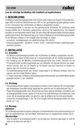
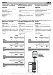
3. INSTALLATION AND CONNECTIONS<br />
The dimmer has a width of 1 module unit (1U) and can be mounted in a<br />
DIN-rail cabinet. For the connection of the load and the necessary power<br />
supply, see wiring diagrams below.<br />
L<br />
230V~<br />
N<br />
<strong>05</strong>-703<br />
ε<br />
R,L,C<br />
40...400W<br />
40...400VA<br />
230V~50Hz (ta=35°C)<br />
L CEBEC<br />
14<br />
<strong>05</strong>-703<br />
ε<br />
R,L,C<br />
40...400W<br />
40...400VA<br />
230V~50Hz (ta=35°C)<br />
L CEBEC<br />
14<br />
NOTICE: This dimmer is only provided with an ‘L’ terminal. An ‘N’ terminal<br />
cannot be connected to the dimmer!<br />
4. OPERATION<br />
4.1 Normal operation:<br />
Lamps connected via dimmers cannot be activated to the maximum light<br />
intensity. The amount of light will always be smaller when compared to<br />
an identical lamp that is directly connected to the network. In case of a full<br />
charge, the dimmer will dissipate max 4W.<br />
Remote control via NO contacts (not lit). Press briefly to switch on or<br />
off.<br />
Press longer to decrease or increase. When pressing long, the direction<br />
is reversed with each interruption (increase -> stop -> decrease -> stop<br />
-> increase -> etc). Once the maximum intensity is reached, the level will<br />
remain the same even if the push button is pressed longer. The last level<br />
before switching off can be saved in the memory (cfr. §4.4). Up to 30 NO<br />
contacts (07-000) can be connected in parallel (max distance 100m). The<br />
push buttons are not galvanically isolated.<br />
A LED indicates the chosen dimming mode.<br />
The LED lights steadily (green): the dimmer functions in reverse phase<br />
control.<br />
The LED blinks (green): the dimmer functions in phase control.<br />
<strong>05</strong>-703<br />
4.2 Automatic switching:<br />
The LED blinks (red):<br />
- because of overload, the dimmer cannot function in reverse phase control<br />
(the load is too inductive). The dimmer automatically switches back to<br />
phase control. Confirm by pressing a control. The dimmer now functions<br />
in phase control. During the switch, the lighting will be switched off.<br />
The LED lights steadily (red):<br />
- because of overload, the dimmer cannot function in phase control (the<br />
load is too capacitive). The dimmer automatically switches to reverse<br />
phase control. Confirm by pressing a control. The dimmer now functions<br />
in reverse phase control. During the switch, the lighting will be switched<br />
off.<br />
4.3 Reinitializing:<br />
- Every time a new load is connected (e.g. use of low voltage halogen<br />
instead of incandescent lamps), it is recommended to reinitialize the<br />
dimmer.<br />
- The dimmer reinitializes itself when a push button is controlled during<br />
the activation of the power supply voltage. The dimmer then returns to<br />
the standard operating mode, i.e. reverse phase control. The red LED<br />
lights for approx. 10s. in confirmation of the setting. During these 10s.,<br />
the dimmer cannot be controlled.<br />
4.4 Memory function:<br />
The dimmer can be used with or without memory.<br />
This mode is factory preset. Press the push button for 10s. to modify this<br />
mode. After 10s. the light level will switch from the maximum to 50%<br />
to indicate the standard function is switched off. Immediately release<br />
the push button after this setting. Repeat this action to reactivate the<br />
memory mode.<br />
With memory function the dimmer is activated on the minimum light intensity<br />
the first time. Afterwards, the dimmer switches to the last set value.<br />
With memory<br />
Brief press = on at previous level / off<br />
Long press when “off” = dimming up from 0%<br />
Dimming up: dimmer stops at maximum light intensity<br />
Dimming down: dimmer stops for 2s. at min. and then dims up<br />
Every new (long) press reverses the dimming direction.<br />
Without memory<br />
Brief press = on at maximum level/off. The rest of the operation is analogous<br />
to the operation “with memory”.<br />
Push button control:<br />
Capacity Vermogen (W)<br />
brief press < 400ms. long press > 400ms.<br />
= on/off = dimming up/down<br />
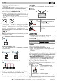
4.5 Capacity diagram:<br />
420<br />
400<br />
380<br />
360<br />
340<br />
320<br />
Capacity Vermogen bij at 50Hz 50Hz<br />
0 35 50<br />
In case the dimmers are placed near eachother, they can be loaded for<br />
max. 80%.<br />
5. PRODUCT MAINTENANCE<br />
Regular controlling of the connections and the ventilation in the<br />
cupboard.<br />
6. TROUBLESHOOTING<br />
The dimmer is provided with a LED which indicates the load condition.<br />
If the LED is not lit:<br />
- the dimmer is turned off (load not dimmable, neither in phase control<br />
nor in reverse phase control)<br />
- the mains voltage is not connected<br />
- the load is not connected or is too high<br />
- the lamp or the used cable is defective<br />
- the thermal protection is activated<br />
- combination of the above-mentioned causes<br />
If the red LED continuously blinks or lights, even after you pressed a push<br />
button (see 4.2. Automatic switching), the dimmer operates according to<br />
the correct dim principle.<br />
This situation is an indication of:<br />
- overload<br />
- overvoltage or overcurrent<br />
- short circuit<br />
- a non-dimmable load.<br />
The dimmer is provided with thermal protection. If the temperature rises<br />
too high because of overhead, the dimmer is automatically dimmed to<br />
approx. 40%. In case the temperature continues to increase, the dimmer<br />
is switched off.<br />
In this case you should:<br />
SA NV Industriepark West 40, B-9100 Sint-Niklaas — Tel 32 (0)3 760 14 70 — Fax 32 (0)3 777 71 20 — e-mail: support@niko.be — www.niko.be — www.niko.nl — www.niko.fr <strong>PM030</strong>-<strong>094R<strong>05</strong>262</strong><br />
t a (°C)<br />
ε<br />
R,L,C<br />
14<br />
CEBEC<br />
- Check whether the load is not too high, considering the power factor of<br />
the ferromagnetic transformers.<br />
- Check the temperature in the distribution board (max 35°C). If this is<br />
too high, you need to provide extra ventilation. Provide an outlet on the<br />
top of the board. Install a ventilator if necessary.<br />
- If several modules are placed next to each other: provide an interspace<br />
of at least 1 module via adjusted blind panels.<br />
7. USAGE NOTICE<br />
- When mounting the dimmer near to an audio installation it is recommended<br />
to provide the connecting wires between the different parts of the installation<br />
with shielded wire.<br />
- Signals sent via the mains can disturb the functioning of the dimmer. A<br />
PLC filter is built in to suppress this effect.<br />
- In normal use, this dimmer will produce a limited amount of heat. You<br />
have to provide a heat outlet. Do not cover the dimmer with isolating<br />
material. Keep in mind that the maximum amount of power is limited<br />
when several dimmers are placed on top of or next to each other.<br />
- When several dimmers are built into a distribution board, the temperature<br />
in this board can be higher than the ambient temperature. This can<br />
influence the functioning of the dimmer (limited maximum amount of<br />
power – thermal protection). Provide enough ventilation in the distribution<br />
board so that the board temperature is always lower than the ta value<br />
indicated on the appliance (35°C). Do not place the dimmers next to<br />
each other when they are all loaded to the maximum.<br />
- When using halogen lighting with ferromagnetic transformers, pay<br />
attention to the output of the transformers. Load these transformers<br />
with at least 80% of their normal power. Pay attention to the output of<br />
the used transformer when determining the total load of the dimmer. The<br />
transformer has to be suited for dimming.<br />
- Electronic transformers can be out of balance when the wire length<br />
between the transformers and the lamps is longer than 2m.<br />
- Conduct of the appliance after power cut < 3s.: back to previous situation.<br />
Conduct of the appliance after power cut > 3s.: the dimmer remains<br />
switched off.<br />
- The dimmer is never deconnected electrically from the mains by operating<br />
the control. All parts are therefore always live even if the load (e.g. the<br />
light) is switched “off”.<br />
- These dimmers are not suitable for controlling motors unless the specific<br />
safety requirements are guaranteed by external systems.<br />
8.TECHNICAL DATA<br />
- Mains supply: 230V~ ±10%, frequency 50Hz<br />
- Dimensions: H 92,4 x D 66 x W 17,5mm<br />
- Mounting: DIN-rail<br />
- Weight: ±74g<br />
- Ambient temperature: ta = 35°C<br />
- For use in an environment with a non-condensing atmospheric humidity<br />
- Own consumption: 2W<br />
- Max. cover temperature (tc): 90°C<br />
- Max. wire diameter per terminal:<br />
- power supply and load: 2 x 1,5mm 2 or 1 x 2,5mm 2<br />
- push button input: 2 x 1,5mm 2<br />
- Min. load: 40W / 40VA<br />
- Max. load: 400W / 400VA<br />
- Voltage drop over dimmer: max. -5%<br />
- Protection:<br />
- thermal overload protection<br />
- short circuit protection<br />
- Push buttons for control: 230V, 5mA (no galvanic isolation)<br />
- Max. distance to last push button: 100m<br />
- Complies with the norms: EN60669-2-1 and EN55015<br />
9.GUARANTEE PROVISIONS<br />
- Period of guarantee: 2 years from date of delivery. The delivery date is<br />
the invoice date of purchase of the product by the consumer. If there is<br />
no invoice, the date of production applies.<br />
- The consumer is obliged to inform <strong>Niko</strong> in writing about the defect, within<br />
two months after stating the defect.<br />
- In case of a failure to conform, the consumer has the right to a repair or<br />
replacement (decided by <strong>Niko</strong>) free of charge.<br />
- <strong>Niko</strong> cannot be held liable for a defect or damage as a result of an incorrect<br />
installation, improper or careless use or wrong usage or transformation<br />
of the goods.<br />
- The compulsory regulations of the national legislation concerning the<br />
sales of consumer goods and the protection of the consumers in the<br />
countries where <strong>Niko</strong> sells, directly or via sister or daughter companies,<br />
chain stores, distributors, agents or permanent sales representatives, take<br />
priority over the rules and regulations mentioned above.