IMS Measuring Systems for Tube Mills
In order to ensure economical and future-oriented production of seamless tubes, it is necessary to know the properties of product after every single one of the typically three forming stages. The ever stricter demands being placed on the finished product „tube“ regarding uniformity and compliance with tighter tolerance limits with simultaneous savings in energy and raw materials necessitate a high degree of process reliability, which can only be achieved with precise, operationally reliable and durable measuring equipment. To verify the quality of the product, also to the users of the tubes, all product parameters measured are archived, monitored and analyzed. In this way it is possible to make information available on every single tube produced, both directly during the production process and months after delivery too.
In order to ensure economical and future-oriented production of seamless tubes, it is necessary to know the properties of product after every single one of the typically three forming stages.
The ever stricter demands being placed on the finished product „tube“ regarding uniformity and compliance with tighter tolerance limits with simultaneous savings in energy and raw materials necessitate a high degree of process reliability, which can only be achieved with precise, operationally reliable and durable measuring equipment.
To verify the quality of the product, also to the users of the tubes, all product parameters measured are archived, monitored and analyzed. In this way it is possible to make information available on every single tube produced, both directly during the production process and months after delivery too.

Create successful ePaper yourself
Turn your PDF publications into a flip-book with our unique Google optimized e-Paper software.
<strong>IMS</strong> <strong>Measuring</strong> <strong>Systems</strong><br />
<strong>Tube</strong> <strong>Mills</strong>
MEASURING SYSTEMS FOR THE<br />
STEEL, METAL AND ALUMINIUM INDUSTRIES<br />
Precision out of passion,<br />
quality out of conviction and<br />
innovation out of tradition<br />
X-ray measuring systems, isotope measuring systems<br />
and optical measuring systems from the world’s<br />
leading manufacturer <strong>IMS</strong> have been a guarantee <strong>for</strong><br />
highest product quality in the production and processing<br />
of steel, aluminium and non-ferrous metals since<br />
1980.<br />
Our non-contact measuring and detection systems are<br />
used in the steel, metal and aluminium industries wherever<br />
meticulous material testing is required to guarantee<br />
the highest standards of quality – worldwide under<br />
the toughest operating conditions.<br />
Both in hot production, such as continuous casting<br />
plants, hot rolling mills and tube mills, where shimmering<br />
surfaces, heat, dirt and moisture are common, as<br />
well as in cold rolling mills and service centres, measuring<br />
systems from <strong>IMS</strong> measure and detect reliably and<br />
with highest precision.<br />
Exactly reproducible measurements and evaluations in<br />
real time optimise your production lines and increase<br />
product quality while simultaneously reducing production<br />
costs and reject rates.<br />
<strong>IMS</strong> MEASURING TASKS AT A GLANCE<br />
ELECTROACOUSTICS/<br />
MAGNETICS<br />
Inclusions / Shell Defects<br />
Width (Radar)<br />
Thickness (Radar)<br />
RADIOMETRIC<br />
MEASURING SYSTEMS<br />
Thickness<br />
Thickness Profile<br />
Profile / Wedge / Edge Drop<br />
Coating<br />
Coating Profile<br />
<strong>Tube</strong> Thickness<br />
<strong>Tube</strong> Profile<br />
Phase Content<br />
OPTICAL<br />
MEASURING SYSTEMS<br />
Thickness<br />
Width<br />
Position<br />
Edge Cracks<br />
Holes<br />
Pinholes<br />
Shape and Diameter<br />
Evenness / Flatness<br />
Coating<br />
2D / 3D Surface Inspection<br />
QUALITY MANAGEMENT<br />
MEVINET-Q<br />
Data Archiving<br />
Data Analysis<br />
Logging<br />
Production Tracking<br />
Quality Evaluation<br />
Claim Evaluation<br />
FORCE MEASUREMENT<br />
Strip- / Web Tension<br />
Shape / Flatness<br />
CONTROL SYSTEMS<br />
Coating<br />
Shape / Flatness AFC<br />
2 3
MEASURING SYSTEMS IN TUBE MILLS<br />
MEASURING SYSTEMS IN TUBE MILLS<br />
<strong>Tube</strong> Production and Metrology<br />
<strong>Measuring</strong> Principle and<br />
Physical Influencing Factors<br />
Production of seamless tubes is dating back<br />
to an invention of the Mannesmann Brothersin 1885.<br />
In order to ensure economical and future-oriented<br />
production of seamless tubes, it is necessary to know<br />
the properties of product after every single one of the<br />
typically three <strong>for</strong>ming stages.<br />
The ever stricter demands being placed on the finished<br />
product „tube“ regarding uni<strong>for</strong>mity and compliance<br />
with tighter tolerance limits with simultaneous savings<br />
in energy and raw materials necessitate a high degree<br />
of process reliability, which can only be achieved with<br />
precise, operationally reliable and durable measuring<br />
equipment.<br />
To verify the quality of the product, also to the users<br />
of the tubes, all product parameters measured are<br />
archived, monitored and analyzed. In this way it is possible<br />
to make in<strong>for</strong>mation available on every single tube<br />
produced, both directly during the production process<br />
and months after delivery too.<br />
General measuring principle<br />
<strong>Tube</strong> wall thickness measuring systems work by the<br />
irradiation principle – a radiation source (transmitter) is<br />
arranged opposite to an ionization chamber (receiver).<br />
A measuring object (tube) located between the transmitter<br />
and receiver absorbs a part of the radiation. The<br />
residual radiation detected by the ionization chamber<br />
generates an electric current, which is processed,<br />
digitalized and then sent to a central signal processing<br />
system <strong>for</strong> calculation of the tube wall thickness.<br />
Double-wall measurement<br />
complete tube circumference<br />
and typical rolling<br />
shapes of different tube<br />
inside contours can be<br />
determined.<br />
OBJECTIVES<br />
Continuous acquisition and storage of all<br />
measured values, production parameters and<br />
system events<br />
Feedback of the measured values to the pilot<br />
control and / or tracking of the control devices of<br />
the rolling units<br />
Targeted error diagnosis to support the operator<br />
High availability of the measuring system<br />
PROFITABILITY<br />
Deliberate utilization of the lower wall thickness<br />
limits with simultaneous equalizing of the tube<br />
wall profile along the complete length of the<br />
tube according to the classifications and special<br />
customer requirements<br />
Reduction in downtimes after dimensional<br />
changes as manual sampling and manual roll<br />
adjustment are not necessary<br />
Increase in material yield with simultaneous<br />
savings in feedstock and energy<br />
<strong>Measuring</strong> principle<br />
Mass Measurement<br />
Signal processing<br />
electronics<br />
In the 1, 2 or 4-Channel version the complete<br />
mass of the tube in the respective<br />
measuring plane is measured – the<br />
wall thickness indicated corresponds<br />
to the mean of the tube cross section.<br />
This measuring geometry is there<strong>for</strong>e<br />
typically used <strong>for</strong> small tube dimensions,<br />
where the tube wall contour was<br />
already determined be<strong>for</strong>e the finished<br />
tube dimensions were reached or is of<br />
little interest.<br />
Double-wall measurement<br />
In the multichannel version (5, 9 or 13-Channel) of the<br />
system the tube wall is irradiated respectively at two<br />
points, i.e. twice. The beams are arranged uni<strong>for</strong>mly<br />
around the center of the measuring system, as a result<br />
of which the wall thickness is determined around the<br />
Influencing factors<br />
The measurement of wall thickness, i.e. the measuring<br />
effect at the moment of measurement, depends on the<br />
following three main influencing factors:<br />
<strong>Measuring</strong> piece position<br />
<strong>Measuring</strong> piece temperature<br />
<strong>Measuring</strong> piece alloy<br />
These influencing factors are taken into account either<br />
through separate measurement or using customer data<br />
specifications.<br />
The measuring piece position is measured with the help<br />
of CCD line scan cameras.<br />
The position in<strong>for</strong>mation and tube dimensions are then<br />
used to calculate the correcting parameters <strong>for</strong> wall<br />
thickness.<br />
The measuring piece temperature is measured with<br />
a colorimetric or ratio pyrometer depending on the<br />
production temperature. The correcting parameter <strong>for</strong><br />
the wall thickness can then be calculated based on<br />
From top to bottom:<br />
Exit Stretch Reducing Mill – 1-Channel system<br />
dilatometer curves stored in the system.<br />
Internal view sources/detectors – 13-Channel system<br />
If grades of steel whose alloys differ from the standard<br />
Entry Reheating Furnace - 9-Channel system<br />
alloys are rolled, the correction values are also calculated<br />
here based on data specifications.<br />
4 5<br />
Receiver<br />
(Ionization<br />
chamber)<br />
<strong>Tube</strong><br />
Transmittter<br />
(Source)<br />
Massmeasurement<br />
eccentric<br />
tube<br />
<strong>Measuring</strong> piece position measurement<br />
CCD- line scan camera<br />
Backlight
MEASURING SYSTEMS IN TUBE MILLS<br />
MEASURING SYSTEMS IN TUBE MILLS<br />
System Configuration<br />
Signal Processing<br />
Configuration<br />
The measuring systems are designed <strong>for</strong> the particular<br />
measuring task and rolling mill configuration in cooperation<br />
with the customer. A measuring system usually<br />
consists of the following components:<br />
Gauge (measuring frame in C- or O-frame shape<br />
with one to 13 measurement axes)<br />
Further sensor measuring systems to determine<br />
diameter, ovality, diameter profile, temperature,<br />
length and speed<br />
Auxiliary components <strong>for</strong> the gauge such as<br />
power supplies and monitoring equipment,<br />
cooling systems, etc.<br />
Central signal processing unit with multiprocessor<br />
system including operation, visualization<br />
and necessary network components<br />
Visualization stations <strong>for</strong> the operating and<br />
maintenance personnel<br />
Quality management system <strong>for</strong> documentation<br />
and archiving of tube and system data over longer<br />
periods of time<br />
Disturbance compensation<br />
To obtain exact measured data, the following influences<br />
must be compensated:<br />
Dirt, e.g. scale, dust, lubricants, etc.<br />
<strong>Measuring</strong> piece position changes on the roller<br />
table<br />
<strong>Measuring</strong> piece temperature, <strong>for</strong> calculation of<br />
cold or hot dimensions<br />
<strong>Measuring</strong> piece alloys deviating from standard<br />
alloys<br />
The influences of the disturbances are measured<br />
with the help of suitable sensors or obtained from<br />
data specifications and compensated by mathematical<br />
processes or automatic adjustment procedures.<br />
Signal transmission<br />
The detector signals are digitalized in the C- or O-frame<br />
and transferred to the measured value processing unit<br />
via an Ethernet network system. Fiber optic transmission<br />
components are used in the case of long distances<br />
between the gauges and the central signal processing unit.<br />
MEVInet<br />
The powerful multiprocessor system MEVInet is responsible<br />
<strong>for</strong> complete evaluation of measured values,<br />
monitoring of the measuring system as well as operation,<br />
visualization, data management and quality assurance.<br />
The individual components are connected to each other<br />
by a fast data network.<br />
The computer system MEVInet consists of the following<br />
main components:<br />
Real Time computer<br />
Operating system Windows<br />
Runtime system logiCAD<br />
Server, HMI<br />
Operating system Windows<br />
MS SQL-Server<br />
Visual Basic / <strong>IMS</strong> Dataviewer<br />
Project planning system<br />
logiCAD to IEC 1131<br />
(Freely programmable control and regulation)<br />
Comprehensive monitor screens enable optimum<br />
operation of the measuring system as well as userfriendly<br />
service and maintenance work. Optimization<br />
and long-term support of the measuring systems installed<br />
around the world are effected by remote maintenance<br />
via internet.<br />
The measured data is evaluated according to customer<br />
requirements and sent to master systems.<br />
The tube measuring system determines the following<br />
variables:<br />
Mean wall thickness<br />
Individual wall thickness around the tube<br />
circumference *<br />
Eccentricities of first to sixth order*<br />
<strong>Tube</strong> cross sectional profile *<br />
Outside diameter, ovality and diameter profile<br />
Temperature and length<br />
All measured values are available directly during<br />
measurement as online display and are shown at<br />
the end of the measurement as profile along the<br />
tube length<br />
Long-term data acquisition and statistical<br />
distribution<br />
* Dependent on type of system<br />
HMI 1<br />
HMI 2 HMI 3<br />
GAUGE COMPUTER ROOM OPERATION, QUALITY ASSURANCE<br />
Ethernet<br />
V-Client<br />
Windows<br />
V-Client<br />
Windows<br />
V-Client<br />
Windows<br />
Network<br />
Customer / <strong>IMS</strong><br />
HMI<br />
HMI<br />
HMI<br />
Ethernet<br />
Q-Server<br />
Windows<br />
Raid 1<br />
Network<br />
<strong>IMS</strong>-Computer<br />
RTR1<br />
Ethernet<br />
Remote access<br />
Ethernet<br />
MC-Server<br />
Windows<br />
logiCAD<br />
MC-Server<br />
Windows<br />
logiCAD<br />
MC-Server<br />
Windows<br />
logiCAD<br />
MC-Server<br />
Windows<br />
logiCAD<br />
Network<br />
<strong>IMS</strong>-<strong>Measuring</strong><br />
equipment<br />
RTC = Real Time Computer<br />
HMI = Operation and Visualization<br />
Ethernet<br />
Control and optimisation level<br />
Customer<br />
<strong>Measuring</strong> system<br />
Weight measurement<br />
bloom be<strong>for</strong>e Rotary<br />
Hearth Furnace<br />
<strong>Measuring</strong> system<br />
Diameter measurement<br />
and length measurement<br />
hollow bloom<br />
<strong>Measuring</strong> system<br />
Temperature measurement<br />
hollow bloom be<strong>for</strong>e<br />
PQF / FQM<br />
<strong>Measuring</strong> system<br />
Temperature measurement<br />
shell behind Reheat<br />
Furnace, be<strong>for</strong>e Stretch<br />
Reducing Mill<br />
<strong>Measuring</strong> system<br />
Temperature<br />
measurement bloom<br />
be<strong>for</strong>e Rotary Piercing Mill<br />
<strong>Measuring</strong> system<br />
Temperature measurement<br />
mandrel bar of PQF /FQM<br />
<strong>Measuring</strong> system<br />
Thickness measurement,<br />
temperature, diameter and<br />
length shell behind PQF /<br />
FQM<br />
<strong>Measuring</strong> system<br />
Thickness measurement,<br />
temperature, diameter and<br />
length tube behind Stretch<br />
Reducing Mill<br />
6 7
MEASURING SYSTEMS IN TUBE MILLS<br />
MEASURING SYSTEMS IN TUBE MILLS<br />
<strong>Tube</strong> <strong>Mills</strong> and Typical<br />
<strong>Tube</strong> Contours<br />
Concentric tube<br />
Center of outside diameter<br />
=<br />
Center of <strong>IMS</strong> system<br />
Center of<br />
inside diameter<br />
Max.<br />
wall thickness<br />
Rotary piercing mill and press<br />
In the first <strong>for</strong>ming step in tube production the solid<br />
bloom is „pierced“, i.e. a rolling or pressing process<br />
turns the solid material into hollow material (hollow<br />
bloom).<br />
In the rotary piercing method, which is the most widespread<br />
process in use today <strong>for</strong> the first rolling stage,<br />
the tensile stresses occurring inside the bloom, caused<br />
by the two staggered rolls (skew rolls) running against<br />
each other, are used to tear open a hole shortly be<strong>for</strong>e<br />
the piercing mandrel. The process is there<strong>for</strong>e less a<br />
mechanical „drilling“ than a „widening“ or „pulling on“.<br />
In the pressing method, which is often used in the preliminary<br />
stage of Pilger <strong>Mills</strong>, a die is pressed into the<br />
bloom under high pressure so that a hole is <strong>for</strong>med in<br />
the bloom by transverse impact.<br />
Eccentricity<br />
In the ideal case both piercing methods should <strong>for</strong>m a<br />
concentric hollow bloom, i.e. the center of the inside<br />
radius is identical to the center of the outside radius.<br />
Eccentric tube<br />
Min.<br />
wall thickness<br />
As a result of the rotation of the bloom<br />
during the rolling process, the eccentricity<br />
has a spiral shape in dependence<br />
on the feed angle of the skewed rolls.<br />
The eccentricity <strong>for</strong>med in the bloom<br />
press only changes in amplitude, and<br />
not in orientation, along the length of<br />
the tube.<br />
MPM and Sizing Mill<br />
In an MPM (Multistand Pipe Mill) and<br />
Sizing Mill two-roll stands arranged alternately<br />
at 90° to each other are used.<br />
In the MPM the rolls roll against a<br />
mandrel bar, i.e. the rolls reduce the<br />
wall thickness while retaining a constant inside diameter.<br />
The outside contour only becomes round in the<br />
so-called extractor mill (MPM extractor), which is not<br />
reached by the mandrel (retained mandrel), but then<br />
previous irregularities in the inside contour are moved.<br />
Typical shapes occurring here are an internal oval and/<br />
or an internal quadrangle (cloverleaf).<br />
The causes of this are:<br />
Uneven or offset rolls<br />
Rolls that are opened too wide or closed too far<br />
The shape is typically constant along the complete<br />
length of the tube.<br />
Push-Bench, Stretch Reducing Mill, Sizing Mill,<br />
PQF ® - and FQM- <strong>Mills</strong><br />
As an alternative to the a<strong>for</strong>ementioned two-roll mills,<br />
three-roll mills are used also.<br />
The Push-Bench process differs from the Stretch<br />
Reducing and Sizing Mill in that the rolls roll against an<br />
internal tool, the so-called mandrel bar, similarly to in an<br />
MPM mill. The mill stands are not driven – the mandrel<br />
bar with the hollow bloom attached to is pushed.<br />
Most modern rolling mills, the PQF ® or FQM <strong>Mills</strong>,<br />
are three-roll mills too and are using the same principle<br />
as the MPM mill to ensure the appropriate elongation<br />
of the material. Here also the retained mandrel bar will<br />
work as an internal tool.<br />
The Stretch Reducing and Sizing Mill produce the outside<br />
diameter and wall thickness of the finished tube.<br />
This is done by arranging numerous three-roll stands,<br />
which can be driven jointly or separately, one behind the<br />
other. In Stretch Reducing <strong>Mills</strong> with individual or group<br />
drives the wall thickness can be controlled locally using<br />
an automation system.<br />
All mentioned mill types produce a typical shape of an<br />
internal triangle or internal hexagon.<br />
Measured value display<br />
Very different gauge types can be used in the three-stage<br />
rolling process depending on the measuring task, which<br />
is reflected by different displays. In the field of mass<br />
measurement the mean wall thickness along the tube<br />
length is shown.<br />
As additional functionality the measuring system<br />
can determine the lengths of the thickened ends on<br />
stretch-reduced finished tubes in order to control a<br />
rotary saw by use of these tube length positions.<br />
Using numerous gauges in the passline, it is possible<br />
to monitor the control intervention of the automation<br />
system easily.<br />
This is done by comparing the measured data on the<br />
shell, which is stored temporarily, with the measured<br />
data on the finished tube.<br />
In addition to in<strong>for</strong>mation on the mean wall characteristics,<br />
the Multi-Channel gauges determine the internal<br />
contour of the tube up to the sixth order (internal<br />
hexagon) depending on the number of channels (5, 9 or<br />
13-Channel).<br />
Internal tube contour of an PQF ® tube<br />
Various external influences, however, cause the two<br />
centers to be moved from this ideal position more or<br />
less strongly, resulting in an eccentric tube contour. The<br />
following main influences lead to an eccentric tube geometry:<br />
Internal oval and internal quadrangle<br />
Internal triangle and internal hexagon<br />
Unequal temperature distribution in the hollow<br />
bloom<br />
Imprecise centering of the bloom<br />
Worn or defective piercing mandrels<br />
Evaluation “thickened ends”<br />
8 9
MEASURING SYSTEMS IN TUBE MILLS<br />
MEASURING SYSTEMS IN TUBE MILLS<br />
High-resolution<br />
Diameter Profile Measurement<br />
Diameter profile measuring system in a PQF ® Mill<br />
New rolling technologies in the production of seamless<br />
steel tubes such as individually adjustable rollers<br />
in three-roll stands in PQF ® or FQM <strong>Mills</strong> or<br />
adjustable end stands in stretch reducing mills have<br />
made suitable and cost-efficient measuring systems<br />
necessary to meet the stricter demands <strong>for</strong> transparency<br />
in the rolling process and maximum accuracy<br />
in measurement.<br />
This demand can be met optimally using highprecision<br />
laser triangulation sensors. For this preferably<br />
18 or 24 sensors are arranged circularly<br />
around the circumference of the tube. Through<br />
synchronization of the individual sensors among each<br />
other, the measured data of all sensors are outputted<br />
simultaneously at measuring rates in millisecond<br />
range, resulting in a distortion-free representation of<br />
the outside profile of the tube.<br />
This configuration is particularly interesting in combination<br />
with a Multi-Channel wall thickness measuring<br />
system because it represents a fully integrated solution<br />
<strong>for</strong> measurement of all geometric parameters on<br />
hot tube requiring only one complete gauge.<br />
A version as independent gauge without wall thickness<br />
measuring system is also available.<br />
<strong>IMS</strong> has been using laser triangulation sensors from<br />
the Swedish company LIMAB, based in Gothenburg,<br />
since 2007 to determine tube position as an alternative<br />
to CCD camera systems. The business relationship<br />
between LIMAB and <strong>IMS</strong> was up-graded to a partnership<br />
in the field of diameter measurement in 2009<br />
with integration of high-resolution diameter measurement<br />
by means of LIMAB measuring heads into the<br />
<strong>IMS</strong> Multi-Channel tube wall measuring system.<br />
SYSTEM FEATURES<br />
Equipped with 18 or 24 sensors, other versions<br />
on request<br />
Data transmission via Ether-Net at up to<br />
1000 kbit/s<br />
Installation on water-cooled protective ring and<br />
behind protective doors with heat protection<br />
shields <strong>for</strong> measurement in hot environments<br />
Protection against contamination by pressure<br />
blower<br />
Easy-to-use calibration equipment<br />
<strong>Measuring</strong> principle and configuration<br />
The measuring principle used by the individual<br />
measuring heads is based on a distance measurement<br />
by means of optical triangulation.<br />
Triangulation<br />
measuring principle<br />
A laser point is dropped<br />
on to the surface of the<br />
material to which the distance<br />
is to be measured.<br />
The laser point is reflected<br />
diffusely by the surface.<br />
The light of the laser point<br />
is imaged within the measuring<br />
range of the measuring<br />
head on a CCD line<br />
(charge coupled device)<br />
via an optical system. The<br />
axis of the optical system<br />
is locked on a fixed angle to the outlet direction of<br />
the laser beam.<br />
By analyzing the position with the highest light<br />
intensity on the CCD line and based on the fixed<br />
geometrical relationship (triangulation), the position<br />
can be converted to a distance with the help of the<br />
calibration curve stored in every measuring head.<br />
The configuration <strong>for</strong> high-precision determination<br />
of the outside diameter and the profile consists of<br />
several individual sensors arranged in pairs opposite<br />
to each other. Simultaneous determination of the<br />
distances of all sensors to the surface of the material<br />
supplies the basic in<strong>for</strong>mation needed <strong>for</strong> further<br />
calculation of the tube profile.<br />
Configuration<br />
with 18 sensors<br />
mean diameter<br />
At the end of the processing<br />
chain the following<br />
parameters are displayed,<br />
and process correcting<br />
variables derived as result:<br />
minimum and maximum diameter and their<br />
directional position<br />
ovality and evaluation of certain structures such<br />
as true triangular or hexagonal shapes<br />
Diameter, ovality and false-color profile<br />
TECHNICAL DATA SINGLE MEASURING HEAD<br />
TECHNICAL DATA PROFILE MEASUREMEN<br />
<strong>Measuring</strong> head measurement range 200 mm<br />
(standard version)<br />
Stand-Off Distance 100 mm<br />
Resolution 10 µm<br />
<strong>Measuring</strong> frequency 2000 1/s<br />
Wavelength 635 … 670 nm (visible red)<br />
Laser class 3R / 3B<br />
Minimum diameter > 20 mm<br />
Diameter range with up to 400 mm diameter<br />
change possible (freely configurable)<br />
<strong>Measuring</strong> accuracy diameter < ± 25 µm<br />
<strong>Measuring</strong> accuracy ovality< ± 50 µm<br />
18-Channel diameter profile measuring system<br />
LIMAB laser triangulation sensor<br />
10 11
MEASURING SYSTEMS IN TUBE MILLS<br />
MEASURING SYSTEMS IN TUBE MILLS<br />
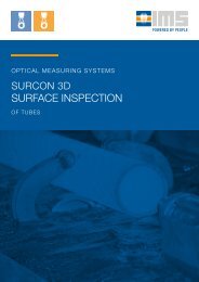
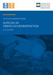
Surface Inspection<br />
surcon 3D <strong>Tube</strong><br />
In tube production, surface defects are often perpetuated<br />
through the complete process chain. Non-stop<br />
surface inspection from billet to finished tube is<br />
there<strong>for</strong>e critical <strong>for</strong> the quality of the final product.<br />
With “surcon 3D <strong>Tube</strong>” surface inspection system,<br />
<strong>IMS</strong> provides tube manufacturers with another<br />
high-quality measurement tool. The system allows to<br />
detect surface defects at a much earlier stage in the<br />
rolling process than be<strong>for</strong>e, and to counteract them<br />
early and effectively by means of concrete corrective<br />
measures.<br />
In particular, the three-dimensional in<strong>for</strong>mation<br />
about the spatial extent of the defects offers a far<br />
more reliable basis <strong>for</strong> deciding to what extent a<br />
surface defect can still be tolerated or whether<br />
immediate intervention in the manufacturing process<br />
is necessary.<br />
In addition, 100% surface inspection ensures that<br />
immediate knowledge is available as to whether a<br />
detected error occurs once, repeatedly on a tube<br />
or at the same length position from tube to tube -<br />
in<strong>for</strong>mation that can be reliably determined is almost<br />
impossible by manual inspection.<br />
BENEFITS<br />
Automatic detection and classification of<br />
relevant defects and geometric data (including<br />
depth and position)<br />
Detection of defects ahead of further processing<br />
steps in the production cycle<br />
Continuous logging of all measuring data,<br />
product parameters and system events<br />
Archiving of data <strong>for</strong> process optimization<br />
Substitution of manual inspection<br />
Examples of defect type detection using surcon 3D<br />
tube surface inspection<br />
The exemplary types of defects shown here as<br />
examples <strong>for</strong> seamlessly rolled tubes are only a<br />
selection of concise samples of how they can be<br />
detected with the help of 3D surface inspection on<br />
finished tubes of different dimensions.<br />
Height profile of a defect in the <strong>for</strong>m of a “shell”<br />
Depending on the error type, the cause of the error<br />
can be determined as quickly as possible and a<br />
corresponding countermeasure can be taken, e.g. a<br />
change of roll stands if all the following tubes were<br />
rolled out with the same significant defects in the<br />
case of a roll breakage or bearing damage.<br />
Height profile of a defect in the <strong>for</strong>m of “washout”<br />
Height profile of a defect in the <strong>for</strong>m of “scale“<br />
Height profile of a defect in the <strong>for</strong>m of “impression”<br />
12 Internal arrangement of 8-Laser-Camera Surface Inspection System<br />
8-Laser-Camera Surface Inspection System installed in seamless hot rolling tube mill<br />
13
MEASURING SYSTEMS IN A SEAMLESS TUBE MILL<br />
MEASURING SYSTEMS IN A SEAMLESS TUBE MILL<br />
PQF ® - / FQM -Mill<br />
PQF®- or FQM-Mill<br />
(Premium Quality Finishing Mill or Fine Quality Mill)<br />
The flowchart shows an example of the measuring equipment<br />
of a modern seamless tube mill. The material is<br />
<strong>for</strong>med in three stages: after heating of the bloom in a<br />
rotary hearth furnace in a rotary piercing mill (piercing), a<br />
PQF ® or FQM mill (elongation) and a Stretch Reducing<br />
Mill (finishing).<br />
Characteristic <strong>for</strong> a PQF ® or FQM mill in comparison<br />
to a conventional MPM mill (Multistand Pipe Mill) is<br />
use of hydraulically adjustable three-roll stands and<br />
a retained mandrel. Thereafter the shells are rolled to<br />
the respective finished tube dimensions required in<br />
a Stretch Reducing Mill comprising up to 28 stands.<br />
Adjustable finishing stands can also be used here.<br />
Multi-Channel measuring system at entry walking beam furnace<br />
4-Channel measuring system behind SRM<br />
T [°C] T [°C] D [mm] L [m]<br />
Optical bloom<br />
identification<br />
(barcode)<br />
Bloom division<br />
<strong>for</strong> optimum<br />
finished tube length<br />
utilisation<br />
Bloom weight<br />
measurement<br />
Bloom heating in<br />
rotary hearth<br />
furnace<br />
High pressure<br />
bloom descaling<br />
Bloom centering<br />
Piercing of bloom<br />
in rotary piercing<br />
mill<br />
Rolling of hollow<br />
bloom to shell in<br />
PQF ® or FQM<br />
mill<br />
Laserscanner Roller table scale Ratio pyrometer Ratio pyrometer<br />
CCD camera<br />
(infrared)<br />
CCD camera<br />
(infrared)<br />
Takeover data<br />
specifications<br />
Takeover bloom<br />
weight<br />
Temperature<br />
measurement<br />
bloom<br />
Temperature<br />
measurement<br />
hollow bloom<br />
Diameter<br />
measurement<br />
hollow bloom<br />
Length<br />
measurement<br />
hollow bloom<br />
S [mm] D [mm] T [°C] L [m] S [mm] D [mm] T [°C] L [m]<br />
Surface<br />
defects<br />
Multi-Channel measuring system<br />
(13-Channel system)<br />
Intermediate<br />
heating of shells in<br />
walking beam<br />
furnace<br />
Stretch reducing of<br />
shells to finished<br />
tube dimensions<br />
4-Channel measuring system<br />
Surface inspection<br />
system<br />
Air cooling of<br />
finished tubes on<br />
cooling bed<br />
Multi-Channel wall<br />
thickness gauge<br />
Laser triangulation<br />
gauge<br />
Radiation<br />
pyrometer<br />
Laser length<br />
gauge<br />
Wall thickness<br />
gauge<br />
Laser triangulation<br />
gauge<br />
Ratio pyrometer<br />
Laser length<br />
gauge<br />
4-, 6- or 8-Laser-<br />
Camera-system<br />
Wall thickness<br />
measurement shell<br />
Diameter and<br />
outside profile<br />
measurement shell<br />
Temperature<br />
measurement shell<br />
Length<br />
measurement shell<br />
Wall thickness<br />
measurement<br />
finished tube<br />
Diameter and<br />
outside profile<br />
measurement<br />
finished tube<br />
Temperature<br />
measurement<br />
finished tube<br />
Length<br />
measurement<br />
finished tube<br />
Inspection<br />
finished tube<br />
14 15
GAUGE TYPES<br />
GAUGE TYPES<br />
Mass Measurement<br />
Double Wall Measurement<br />
1-CHANNEL-SYSTEM<br />
<strong>Measuring</strong> equipment<br />
5-CHANNEL-SYSTEM<br />
<strong>Measuring</strong> equipment<br />
Wall thickness<br />
Diameter<br />
Temperature<br />
Length<br />
Measured values<br />
Wall thickness<br />
Diameter<br />
Temperature<br />
Length<br />
1-Channel, vertical to tube axis<br />
1-Channel, infrared<br />
Radiation or ratio pyrometer<br />
Laser Doppler velocimeter<br />
Mean value, minimum value, maximum value per tube<br />
Mean value, minimum value, maximum value per tube<br />
Mean value, minimum value, maximum value per tube<br />
Total length, length of thickened ends<br />
Wall thickness<br />
Diameter<br />
Temperature<br />
Length<br />
Measured values<br />
Wall thickness<br />
Diameter<br />
Temperature<br />
Length<br />
5-Channel, 5 x 72° offset<br />
2/4-channel, infrared or backlight;<br />
multi-channel by laser triangulation<br />
Radiation or ratio pyrometer<br />
Laser Doppler velocimeter<br />
Mean value, minimum value and maximum value per<br />
tube, plus wall thickness characteristic of first and<br />
second order<br />
Mean value, minimum value, maximum value per tube,<br />
diameter difference (pseudo oval) or diameter profile<br />
Mean value, minimum value, maximum value per tube<br />
Total length<br />
2-CHANNEL-SYSTEM<br />
<strong>Measuring</strong> equipment<br />
9-CHANNEL-SYSTEM<br />
<strong>Measuring</strong> equipment<br />
Wall thickness<br />
Diameter<br />
Temperature<br />
Length<br />
2-Channel, +/- 45° to tube axis<br />
2-Channel, infrared or backlight; multi-channel by laser<br />
triangulation<br />
Radiation or ratio pyrometer<br />
Laser Doppler velocimeter<br />
Wall thickness<br />
Diameter<br />
Temperature<br />
Length<br />
9-Channel, 9 x 40° offset<br />
2/4-Channel, infrared or backlight; multi-channel<br />
by laser triangulation<br />
Radiation or ratio pyrometer<br />
Laser Doppler velocimeter<br />
Measured values<br />
Measured values<br />
Wall thickness<br />
Diameter<br />
Temperature<br />
Length<br />
Mean value, minimum value and maximum value per tube<br />
Mean value, minimum value, maximum value per tube,<br />
diameter difference (pseudo oval) or diameter profile<br />
Mean value, minimum value, maximum value per tube<br />
Total length, length of thickened ends<br />
Wall thickness<br />
Diameter<br />
Temperature<br />
Length<br />
Mean value, minimum value and maximum value per tube,<br />
plus wall thickness characteristic of first to fourth order<br />
Mean value, minimum value, maximum value per tube,<br />
diameter difference (pseudo oval in 2-Channel version)<br />
or diameter profile<br />
Mean value, minimum value, maximum value per tube<br />
Total length<br />
4-CHANNEL-SYSTEM<br />
<strong>Measuring</strong> equipment<br />
13-CHANNEL-SYSTEM<br />
<strong>Measuring</strong> equipment<br />
Wall thickness<br />
Diameter<br />
Temperature<br />
Length<br />
4-Channel, ± 22,5° and ± 67,5° to tube axis<br />
2-Channel, infrared or backlight; multi-channel by laser<br />
triangulation<br />
Radiation or ratio pyrometer<br />
Laser Doppler velocimeter<br />
Wall thickness<br />
Diameter<br />
Temperature<br />
Length<br />
13-Channel, 13 x 27.7° offset<br />
2/4-Channel, infrared or backlight; multi-channel<br />
by laser triangulation<br />
Radiation or ratio pyrometer<br />
Laser Doppler velocimeter<br />
Measured values<br />
Measured values<br />
Wall thickness<br />
Diameter<br />
Temperature<br />
Length<br />
Mean value, minimum value and maximum value per<br />
tube, plus wall thickness difference odd/even channel<br />
pairs<br />
Mean value, minimum value, maximum value per tube,<br />
diameter difference (pseudo oval) or diameter profile<br />
Mean value, minimum value, maximum value per tube<br />
Total length, length of thickened ends<br />
Wall thickness<br />
Diameter<br />
Temperature<br />
Length<br />
Mean value, minimum value and maximum value per<br />
tube, plus wall thickness characteristic of first to sixth order<br />
Mean value, minimum value, maximum value per tube,<br />
diameter difference (pseudo oval in 2-Channel version)<br />
or diameter profile<br />
Mean value, minimum value, maximum value per tube<br />
Total length<br />
16 17
Technical Data<br />
Type Table/Configuration Range<br />
TUBE DATA<br />
<strong>Tube</strong> wall thickness<br />
< 50 mm single wall thickness<br />
<strong>Tube</strong> outside diameter<br />
16 to 750 mm<br />
<strong>Tube</strong> temperature < 1300 °C<br />
<strong>Tube</strong> speed<br />
< 15 m/s<br />
Additional components<br />
Gauge Version<br />
C-frame 1-Channel<br />
(mass measurement)<br />
C-frame 2-Channel<br />
(eccentricity measurement)<br />
O-frame 2-Channel<br />
(mass measurement)<br />
O-frame 4-Channel<br />
(mass measurement)<br />
O-frame 5-Channel<br />
(1st & 2nd order double<br />
wall measurement)<br />
O-frame 9-Channel<br />
(1st to 4th order<br />
double wall measurement)<br />
O-frame 13-channel<br />
(1st to 6th order double<br />
wall measurement)<br />
Material<br />
Alloyed and unalloyed steels, stainless steels, non-ferrous metals on request<br />
TEMPERATURE MEASUREMENT<br />
GAUGE DATA<br />
Gauge<br />
Cooling<br />
Drive unit<br />
Radiation source<br />
Number of sources/detector<br />
Traversing C- or O-frame, special designs on request<br />
Closed cooling circuit, supplied by customer cooling medium<br />
Pneumatic or electric<br />
Isotope Cs 137 (185 or 370 GBq per source), X-ray on request<br />
1 to 13 per gauge<br />
Keller, Land*, Ircon*<br />
DIAMETER, POSITION AND<br />
PROFILE MEASUREMENT<br />
1-camera system infrared<br />
2-camera system infrared<br />
1-camera system backlight<br />
2-camera system backlight<br />
Ionization chamber KG 126 or KG 60<br />
4-camera system backlight<br />
<strong>Measuring</strong> point size<br />
OD 80 to 100 mm (mass measurement), approx. 20 x 60 mm (double-wall measurement)<br />
2+2 camera system backlight<br />
4+2 camera system backlight<br />
MEASURING DYNAMICS<br />
Analog measuring time constant<br />
< 30 ms<br />
Laser-Triangulation (diameter)<br />
Laser-Triangulation (position)<br />
* *<br />
Cycle time data acquisition 500 µs<br />
3D Laser-Triangulation (contour)<br />
Cycle time data processing<br />
Cycle time data output<br />
MEASURING ACCURACY<br />
5 ms<br />
10 ms<br />
3D Laser-Triangulation (SIS)<br />
LENGTH MEASUREMENT<br />
Polytec, Beta Lasermike*<br />
<strong>Tube</strong> wall thickness Application-dependent < ± 0,3 %<br />
<strong>Tube</strong> diameter, position Application-dependent < ± 0,4 % of measuring range end value or < ± 25 µm<br />
Surface defects<br />
> 0,2 mm depth, length / width application-dependent<br />
Standard Option Not available On request<br />
*<br />
<strong>Tube</strong> temperature<br />
<strong>Tube</strong> length<br />
< ± 0,75 % of measuring range end value<br />
< ± 0,1 % of total length plus ± 20 mm end detection<br />
18 19
MEVIweb<br />
Human Machine Interface (HMI)<br />
MEVIweb<br />
User software developed inhouse by <strong>IMS</strong> with<br />
excellent user experience<br />
The impressive per<strong>for</strong>mance of all <strong>IMS</strong> measuring systems<br />
is not only defined by their reliable functionality,<br />
consistently accurate measuring results and impressive<br />
service life. The extremely user-friendly control and regulation<br />
software is also an important factor in the success<br />
of our radiometric and optical measuring systems.<br />
MEVIweb is the logical further development of the wellknown<br />
and previously used automation system MEVInet.<br />
Developed by <strong>IMS</strong>, this human machine interface<br />
uses the latest technology standards and always focuses<br />
on the user and his or her individual requirements.<br />
As an automation system of the latest generation,<br />
MEVIweb fulfils the following tasks using the latest software<br />
and hardware technologies:<br />
The following software extension packages are<br />
available to our customers <strong>for</strong> their individual<br />
control and regulation software requirements:<br />
• Q Lite<br />
• Q Basic<br />
• Q Professional<br />
• Q Data Exporter *<br />
• SPS Programming<br />
* (can only be used with Q Lite, Basic or Professional)<br />
• measurement<br />
• control<br />
• regulation<br />
• visualisation<br />
• quality management<br />
In addition to precise measurement technology, special<br />
emphasis was placed during development on diagnostic<br />
and maintenance support, including the possibility<br />
of remote diagnosis. Programming is effected with modules<br />
according to IEC 61131 of the logi.CAD system,<br />
using standardised operating systems and interfaces.<br />
CONVINCING USABILITY THROUGH:<br />
• Use of newest technologies (JavaScript,<br />
NodeJS, HTML5, CSS, JSON)<br />
• Open communication with standardised,<br />
non-proprietary interfaces<br />
• Large test coverage with unit tests, integration<br />
tests and simulation<br />
• Scalability<br />
• Plat<strong>for</strong>m independence (reduction of dependencies)<br />
• Unified configuration tools & improved user<br />
experience<br />
• Web configuration<br />
• Use of smartphones and tablets possible<br />
• Modern appearance with various customisable<br />
themes<br />
• Clearly structured, user-friendly interface<br />
• Enhanced functionality<br />
20 21
THE <strong>IMS</strong> GROUP<br />
<strong>IMS</strong> as Pioneer<br />
Since its foundation in 1980, <strong>IMS</strong> has successfully faced the ever-growing<br />
requirements of the rolling industry <strong>for</strong> high-per<strong>for</strong>mance measuring systems.<br />
The result: a product portfolio of high-precision, non-contact detecting<br />
systems that covers all measuring tasks arising in your production lines. We<br />
would like to present outstanding system developments, some of which <strong>IMS</strong><br />
was the first manufacturer worldwide to bring to market, thereby establishing<br />
itself as market leader.<br />
1981 – 1983<br />
Successful development of<br />
microprocessor technologies<br />
(1981) and commissioning<br />
of the first optical<br />
width measuring system<br />
(1983) replace conventional<br />
analogue technologies<br />
1981<br />
1988 FIRST<br />
2nd Generation of Multichannel<br />
Profile <strong>Measuring</strong> System<br />
Market launch of the second<br />
generation of monoscopic<br />
isotope thickness measuring<br />
systems (gamma radiation) <strong>for</strong><br />
flat products<br />
1995 FIRST<br />
3rd Generation of Multichannel<br />
Profile <strong>Measuring</strong> System<br />
Market launch of the third generation<br />
of thickness measuring systems <strong>for</strong><br />
flat products, now based on x-ray<br />
radiation<br />
1997 FIRST<br />
Market Launch<br />
of Edge Drop<br />
Strip Edge Profile<br />
<strong>Measuring</strong> System<br />
The first radiometric<br />
strip edge profile<br />
measuring system<br />
<strong>for</strong> high-resolution<br />
measurement of<br />
strip thickness,<br />
wedge and strip<br />
cross profile enters<br />
service<br />
2001 FIRST<br />
Market Launch of<br />
TopPlan Strip Flatness<br />
<strong>Measuring</strong> System<br />
Presentation of the<br />
three-dimensional and<br />
non-contact optical<br />
strip flatness measuring<br />
system TopPlan<br />
2008 FIRST 2014 FIRST<br />
Development Work on<br />
surcon 3D Surface Inspection<br />
<strong>Systems</strong> Begins<br />
As the first manufacturer<br />
worldwide, <strong>IMS</strong> develops a 3D<br />
surface inspection system able<br />
to detect the surface quality of<br />
slabs and billets at temperatures<br />
of even above 1,000°C<br />
using a laser sectioning<br />
technique<br />
2010<br />
Market Launch of a Billet<br />
Contour <strong>Measuring</strong> System<br />
The first measuring system<br />
<strong>for</strong> dimensional measurement<br />
of hot billets and<br />
profiles enters service<br />
successfully<br />
Market Launch of Camera<br />
Cluster <strong>Systems</strong> (CCS)<br />
First deployment of compact<br />
camera cluster systems (CCS)<br />
<strong>for</strong> width, hole and edge crack<br />
detection, slit strip width<br />
measurement, flatness and<br />
evenness measurement, sheet<br />
geometry measurement and<br />
pinhole detection<br />
2017 FIRST<br />
First Deployment<br />
of an XRD Phase<br />
Content <strong>Measuring</strong><br />
System<br />
Successful commissioning<br />
of the<br />
first online phase<br />
content measuring<br />
system based on<br />
x-ray diffraction in a<br />
hot-dip galvanising<br />
line<br />
2020<br />
First Deployment of a Laser<br />
Thickness <strong>Measuring</strong> System<br />
The first laser thickness measuring<br />
system <strong>for</strong> cold-rolled strip<br />
is successfully installed and<br />
commissioned in a slitting line<br />
2022 FIRST<br />
Development of a<br />
Magnetic Strip Flatness<br />
<strong>Measuring</strong> System<br />
Magnetic strip flatness<br />
measuring system <strong>for</strong><br />
tensile strip developed<br />
as an alternative to<br />
conventional shapemeter<br />
rolls<br />
TODAY<br />
1984 FIRST<br />
1st Generation of<br />
Multichannel Profile<br />
<strong>Measuring</strong> System<br />
Market launch of the first<br />
generation of monoscopic<br />
isotope thickness measuring<br />
systems (gamma<br />
radiation) <strong>for</strong> flat products<br />
1990<br />
Market Launch of <strong>Tube</strong><br />
Thickness <strong>Measuring</strong><br />
System<br />
The first high-per<strong>for</strong>mance<br />
measuring system <strong>for</strong><br />
non-contact, continuous<br />
measurement of tube<br />
thickness, geometry,<br />
contour and position enters<br />
service successfully<br />
1996<br />
1999<br />
Development of Modern<br />
X-Ray Components<br />
In-house development of x-ray<br />
generators and control units<br />
specifically optimised <strong>for</strong> use in<br />
<strong>IMS</strong> measuring systems<br />
2002 FIRST<br />
Market Launch of <strong>IMS</strong>pect<br />
Coating Weight <strong>Measuring</strong><br />
System<br />
Commissioning of the first optical<br />
coating weight measuring system<br />
<strong>for</strong> determination of coating<br />
thicknesses in pre- and post-treatments<br />
with chromates, titanium,<br />
zirconium compounds as well as<br />
in chromium-free pre-treatments<br />
First Deployment of<br />
MEVInet-Q Data Archiving System<br />
The first version of the MEVInet-Q data<br />
archiving system, equipped with scalable<br />
software <strong>for</strong> automated acquisition<br />
and visualisation of relevant measurement<br />
data, is deployed<br />
2009 FIRST<br />
2013<br />
2015 FIRST<br />
First Deployment of Radar<br />
Width <strong>Measuring</strong> System<br />
For the first time, a radarbased<br />
measuring system<br />
specially developed <strong>for</strong> use<br />
under even the harshest<br />
environmental conditions in<br />
hot rolling mills enters service<br />
Production of XR Thickness<br />
<strong>Measuring</strong> <strong>Systems</strong> Begins in the USA<br />
The US subsidiary <strong>IMS</strong> <strong>Systems</strong>, Inc. starts<br />
production of x-ray thickness measuring<br />
systems in revised <strong>for</strong>m as compact, modular<br />
solution <strong>for</strong> strip thickness measurement in<br />
cold rolling mills and process lines<br />
Further Development of MEVInet-Q2 Data Archiving System<br />
Optimisation of the MEVInet-Q quality data archiving system as well as its<br />
automated evaluation of measurement data <strong>for</strong> quality assurance purposes<br />
over the entire production process from hot strip, cold strip, material finishing<br />
to dressing and straightening<br />
Market Launch of a Compact X-Ray Generator with Control Unit<br />
Integration of the compact x-ray generator and control unit combined into<br />
one component in <strong>IMS</strong> measuring frames simplifies installation, and enables<br />
faster control and trouble-free operation of the system<br />
2019 FIRST<br />
2021 FIRST<br />
Development of the Inclusion<br />
Detection System (IDS)<br />
The Inclusion Detection System<br />
(IDS), based on the principle<br />
of magnetic flux leakage and<br />
specially developed <strong>for</strong> the early<br />
detection of internal defects and<br />
shell defects in cold-rolled strip<br />
steels, has already entered<br />
service successfully<br />
First Deployment of a Radar<br />
Thickness <strong>Measuring</strong> System<br />
Specially developed <strong>for</strong> the harsh<br />
environmental conditions in hot<br />
rolling mills, the first radar thickness<br />
measuring system enters<br />
service in a Steckel mill<br />
22 23
RESEARCH AND DEVELOPMENT<br />
SERVICE<br />
The Way Forward<br />
24/7 Service<br />
Worldwide<br />
We at <strong>IMS</strong> see ourselves as a self-learning organisation whose corporate<br />
concept is geared towards maintaining a high level of know-how at<br />
all times as the basis <strong>for</strong> our highly developed measuring systems:<br />
non-contact detection systems which, thanks to their innovative and<br />
customer-specific developments, are often not only ahead of the times,<br />
but also of our competitors.<br />
We can only achieve and guarantee this market lead over the long term if<br />
we work together closely with our customers as partners as the concrete<br />
and very individual problems of our customers are our challenges <strong>for</strong><br />
constant new developments of advanced technology that withstands<br />
the harshest conditions thanks to precise yet robust mechanics. Strong<br />
partners from research and engineering round off our competence team.<br />
The result: precision systems of the highest order <strong>for</strong> optimally monitored<br />
processes in hot rolling mills, cold rolling mills and service centres.<br />
As the world market leader <strong>for</strong><br />
measuring systems, we know that<br />
high-precision technology requires a<br />
maximum focus on quality. This also<br />
applies to our high-per<strong>for</strong>mance and<br />
comprehensive service, which turns<br />
our measuring systems into true<br />
full-business solutions.<br />
Worldwide service around the clock – which we offer<br />
and guarantee our customers through our <strong>IMS</strong> Service<br />
Centres distributed strategically around the globe.<br />
Even be<strong>for</strong>e delivery of the new measuring system,<br />
your employees can undergo intensive training in our<br />
in-house academy to ensure optimal integration and<br />
high-per<strong>for</strong>mance operation of the system in your process<br />
sequences from the very beginning. Our service<br />
team will of course take care of maintenance, repair<br />
and any spare parts that may be required <strong>for</strong> constant<br />
smooth operation in your production chain.<br />
Through remote maintenance at the highest technological<br />
level, we are able to carry out error diagnoses<br />
directly when required and guarantee immediate competent<br />
support <strong>for</strong> your employees on site. Your benefit:<br />
optimal service life of all components, while the systems<br />
are and remain adapted to the constant development in<br />
technical requirements.<br />
With our three service packages – Basic, Silver<br />
and Gold – we offer you exactly the service that is<br />
tailored to your requirements and needs. Support via<br />
our toll-free 24/7 telephone hotline is already part of our<br />
Basic package, and direct remote support is available<br />
from Silver onwards. Finally, our <strong>IMS</strong> Gold service as<br />
an all-round carefree package ensures that our service<br />
technicians are deployed on site in the event of a malfunction<br />
and that spare parts are available and delivered<br />
in less than 24 hours.<br />
You want a quote <strong>for</strong> your system? With pleasure!<br />
Simply contact us.<br />
24 25
„Responsibility means to<br />
blame yourself <strong>for</strong> the lack of<br />
sustainability.“<br />
(Ronny Boch, geologist, free author)<br />
Conservation of resources<br />
through precision out of<br />
passion and quality out of<br />
conviction<br />
We at <strong>IMS</strong>, as the world market leader <strong>for</strong> measuring<br />
systems, are aware of our social responsibility of sustainable<br />
management!<br />
To give our customers, suppliers and stakeholders a<br />
transparent insight into concrete measures we have implemented<br />
in the <strong>IMS</strong> Group, we launched the project<br />
<strong>IMS</strong>ocial in close adherence to the principles of Corporate<br />
Social Responsibility (CSR).<br />
But <strong>for</strong> us at <strong>IMS</strong>, <strong>IMS</strong>ocial is more than just a project!<br />
<strong>IMS</strong>ocial is a belief and stands <strong>for</strong> the values of our corporate<br />
philosophy.<br />
After all, the sooner even minor defects – which in steel<br />
products can already render them useless – are detected,<br />
the faster machining processes can be corrected.<br />
And precisely this contributes significantly to active climate<br />
protection as it is no longer necessary to produce<br />
new products to substitute defective ones, thereby saving<br />
energy and water, and also reducing reject rates<br />
significantly.<br />
Learn more about <strong>IMS</strong>ocial and visit us at<br />
www.imsocial.info!<br />
We not only want to achieve sustainability in our products<br />
and customer relations, but also place the same<br />
demands on our social, ecological and economic responsibility.<br />
The first thought that comes to mind in connection with<br />
the non-contact measuring systems from <strong>IMS</strong> <strong>for</strong> the<br />
steel, non-ferrous metal and aluminium industries is<br />
certainly not one of active conservation of resources.<br />
However, our isotope, x-ray and optical measuring systems<br />
do exactly that: they save and preserve resources!<br />
The <strong>IMS</strong> product portfolio comprises numerous measuring<br />
systems and processes <strong>for</strong> various types of measurement.<br />
Our systems deliver and document exceptionally<br />
precise measurement results under the toughest<br />
conditions in hot and cold rolling mills as well as service<br />
centres. In this way it is possible to detect material defects,<br />
surface irregularities, tolerance and dimensional<br />
deviations and many other factors that, in the worst<br />
case, would lead later to material rejects at an early stage<br />
during the manufacturing process.<br />
26 27
<strong>IMS</strong> worldwide<br />
ARGENTINA<br />
AMPEXA<br />
AUSTRALIA<br />
FEC Australia<br />
BRASIL<br />
<strong>IMS</strong> do Brasil<br />
CHINA P.R.<br />
<strong>IMS</strong> Messsysteme<br />
(Shanghai) Co., Ltd.<br />
Shanghai Jiaxuan Intelligent<br />
Technology Co., Ltd.<br />
DUBAI<br />
<strong>IMS</strong> Maco<br />
<strong>Measuring</strong> <strong>Systems</strong> (FCZ)<br />
FINLAND<br />
Beijer Oy<br />
INDIA<br />
<strong>IMS</strong> Maco Services Pvt., Ltd.<br />
INDONESIA<br />
PT. Indojaya Mitra Sarana<br />
ITALY<br />
Mediter S.A.S.<br />
JAPAN<br />
Nireco Corporation<br />
KOREA<br />
<strong>IMS</strong> <strong>Systems</strong> Korea Co., Ltd.<br />
MEXICO<br />
<strong>IMS</strong>SYS Mexico S.A. de C.V.<br />
RUSSIA<br />
<strong>IMS</strong> Service LLC.<br />
SWEDEN<br />
Olsson & Falck AB<br />
SERBIEN<br />
UNICOM<br />
SPAIN<br />
Industrial Equipment and<br />
Consumables, S.L.<br />
SÜDAFRIKA<br />
REMAG (Pty) Ltd.<br />
TAIWAN<br />
Litefluid Engineering Co., Ltd.<br />
TURKEY<br />
<strong>IMS</strong> Metalurji Servis Ltd., Sti.<br />
Tarakcioglu A.S.<br />
USA<br />
<strong>IMS</strong> <strong>Systems</strong> Inc.<br />
VENEZUELA<br />
<strong>IMS</strong> Venezuela C.A.<br />
UNITED KINGDOM<br />
TRC Poole<br />
VIETNAM<br />
<strong>IMS</strong> <strong>Systems</strong> Vietnam Co., Ltd.<br />
Cuong Phat Co., Ltd.<br />
THAILAND<br />
EGYPT<br />
EUROSIA Trading Co., Ltd<br />
A.T.S. Company<br />
POLAND<br />
28<br />
<strong>IMS</strong> <strong>Systems</strong> Poland z o.o.<br />
29
20 of the 20 largest steel and<br />
aluminium manufacturers worldwide<br />
rely on the precision of<br />
<strong>IMS</strong> measuring systems as part<br />
of their quality assurance<br />
4500+<br />
<strong>Measuring</strong> systems in use<br />
750+<br />
Customers in<br />
60+<br />
Countries<br />
30 31
<strong>IMS</strong> Messsysteme GmbH<br />
Dieselstraße 55<br />
42579 Heiligenhaus | Germany<br />
Phone: +49 (0) 2056 / 975 – 0<br />
Fax: +49 (0) 2056 / 975 – 140<br />
info@ims-gmbh.de<br />
www.ims-gmbh.de