BRUSHLESS DC MOTOR MANUAL - PowerTec
BRUSHLESS DC MOTOR MANUAL - PowerTec
BRUSHLESS DC MOTOR MANUAL - PowerTec

You also want an ePaper? Increase the reach of your titles
YUMPU automatically turns print PDFs into web optimized ePapers that Google loves.
<strong>BRUSHLESS</strong> <strong>DC</strong><br />
<strong>MOTOR</strong><br />
<strong>MANUAL</strong><br />
“F” SERIES <strong>MOTOR</strong>S<br />
42T THROUGH 500ATZ FRAMES<br />
INSTALLATION<br />
AND OPERATION<br />
<strong>MANUAL</strong><br />
DECEMBER 2005<br />
POWERTEC Industrial Motors<br />
Mailing address: P.O. Box 2650 Rock Hill, South Carolina USA 29732 PHONE: 803-328-1888<br />
Shipping Address: 2606 Eden Terrace Rock Hill, South Carolina USA 29730 FAX: 803-328-1870<br />
Internet: powertecmotors.com
POWER POWERTEC POWER “F” Series Motor Manual Page 1<br />
WARNING!!! IF YOU DO NOT INSTALL AND SERVICE THIS EQUIPMENT CORRECTLY,<br />
YOU OR SOMEONE ELSE COULD GET HURT.<br />
APPLICATION CHECKLIST<br />
1. UPON RECEIPT<br />
Our Quality Control Department inspects the<br />
motors and packing before shipment. When you<br />
receive it, inspect your order. Look for any<br />
mechanical damage that may have occurred during shipment.<br />
Report any damage you find to the freight carrier FIRST. Then<br />
call POWERTEC for help in assessing the damage.<br />
2. STORAGE<br />
You should store a motor in its original packaging. Keep it in a<br />
clean, dry location, protected from extremes in temperature<br />
and humidity. Rotate the shaft of a stored motor monthly. The<br />
grease may settle in the bearings and harden over time.<br />
Before installation, remove the cosmoline rust prevention<br />
coating from the shaft extensions with a suitable solvent.<br />
3. HANDLING<br />
Use care in handling the motor. Avoid dropping it. Prevent<br />
sudden impacts, especially on the shaft. The lifting lugs are<br />
designed to lift the weight of the motor ONLY. DO NOT use the<br />
lifting lugs of the motor as the sole means to lift other devices,<br />
such as gearboxes, attached to the motor.<br />
4. ENVIRONMENT<br />
The motor ratings are for an altitude of less than 3300 feet<br />
(1000 meters). You must derate the motor for higher altitudes.<br />
DERATING FACTOR<br />
1.20<br />
1.10<br />
1.00<br />
0.90<br />
0.80<br />
0.70<br />
0.60<br />
0.50<br />
0.40<br />
0.30<br />
0.20<br />
0.10<br />
ALTITUDE DERATING CHART<br />
0.00 0 2 4 6 8 10 12 14 16 18 20 22 24<br />
ALTITUDE (X 1000) in feet above sea level<br />
Motors are rated in accordance with NEMA Standard MG1-14.04.<br />
For altitudes below sea level, use standard ratings.<br />
For altitudes above 24,000 feet, consult the factory.<br />
At a specified altitude: Multiply the motor HP by the de-rating factor.<br />
Install the motor in a clean, dry, well-ventilated area away from<br />
heat sources. Air temperature should not exceed 40 °C (104°<br />
Fahrenheit). For higher ambient temperatures, you must<br />
derate the motor. See the graph below.<br />
DERATING FACTOR<br />
1.20<br />
1.10<br />
1.00<br />
0.90<br />
0.80<br />
0.70<br />
0.60<br />
0.50<br />
0.40<br />
0.30<br />
0.20<br />
0.10<br />
AMBIENT TEMPERATURE DERATING CHART<br />
0.00 20 25 30 35 40 45 50 55 60 65 70 75 80<br />
TEMPERATURE °C<br />
Motors are rated in accordance with NEMA standard MG1-12.43.<br />
For ambient temperatures below 40°C, use the 40°C rating.<br />
For ambient temperatures below 0°C, consult the factory.<br />
At a given ambient temperature: Multiply the motor HP by the derating factor.<br />
De-rating is cumulative.<br />
First de-rate for altitude; then de-rate for temperature.<br />
5. GENERAL MECHANICAL INSPECTION<br />
Before you install the motor, verify that the motor shaft is free<br />
to turn and all mechanical parts are in their proper position.<br />
Turn the motor shaft by hand to check for damage to the rotor.<br />
NOTE: If you have power leads shorted together in the<br />
junction box, the motor shaft will not turn.<br />
6. MOUNTING<br />
You can mount the motor in any shaft position as long as you<br />
keep radial and thrust loads within limits. Install foot-mounted<br />
motors on a rigid foundation. You must use shims if the motor<br />
mounting base is uneven. Do not cause unnecessary stress on<br />
feet, frame and bearings by using poor mounting practices.<br />
After installation, make sure that all bolts that hold the motor in<br />
place are tight. See Mounting Bolt Torques on page 14.<br />
12/12/05 © copyright 2000 by POWER POWERTEC POWER POWER Industrial Motors, Inc.
Page 2 POWER POWERTEC POWER “F” Series Motor Manual<br />
7. ALIGNMENT<br />
If the motor is directly coupled to the load, alignment is very<br />
important. The type of coupling device determines alignment<br />
tolerances. Poor alignment allows vibration, resulting in<br />
damage to the coupling, bearings, rotor, or accessory devices.<br />
8. BELTED APPLICATIONS<br />
It is important that you use the correct sheave size and type.<br />
You must select the proper belts. See the Maximum Shaft<br />
Radial Loading Table on page 14. When you size the sheaves<br />
wrong or tension the belts improperly, premature bearing or<br />
shaft failure may occur. Mount the sheave as close as you can<br />
to the motor housing. If you need help on sheave sizing, call<br />
POWER POWERTEC.<br />
POWER<br />
WHEN REMOVING PULLEYS FROM THE <strong>MOTOR</strong> SHAFT,<br />
USE A PROPER PULLER. DO NOT PRY PULLEYS OFF BY<br />
LEVERAGE AGAINST THE FRAME. YOU MAY DAMAGE THE<br />
BEARINGS OR THE RETAINER PLATES BY PLACING STRESS<br />
ON THE <strong>MOTOR</strong> SHAFT RELATIVE TO THE FRAME.<br />
9. OPERATION<br />
After you complete the mounting and alignment steps, you<br />
may make electrical connections. You must follow the<br />
connection diagrams exactly or the motor will not operate.<br />
If turning the wrong way will damage the equipment, verify<br />
motor direction before connecting the load. Monitor motor<br />
current during the first operation of the motor. Compare it to<br />
the motor nameplate value.<br />
Check the motor cooling right after the start-up. Check it at<br />
fifteen-minute intervals until the motor gets to normal<br />
temperature (about four hours at full load).<br />
10. MAINTENANCE<br />
Make the first inspection within a few hours after placing the<br />
motor in service, to catch problems caused by the installation.<br />
Check the motor at least once per month after start-up.<br />
Preventive maintenance means checking the motor often.<br />
Make frequent checks for excess vibration, loose mounting<br />
bolts and belts, odd noises (a steady hum is normal), and high<br />
heat output.<br />
!<br />
FRAME OPERATING TEMPERATURES MAY BE<br />
HIGH ENOUGH TO CAUSE BURNS! KEEP<br />
ALL COMBUSTIBLE MATERIALS AWAY<br />
FROM THE <strong>MOTOR</strong>!<br />
© copyright 2000 by POWER POWERTEC POWER Industrial Motors, Inc. 12/12/05<br />
SUMMARY OF WARRANTY<br />
Brushless <strong>DC</strong> motors built by POWER<br />
POWER<br />
POWERTEC Industrial<br />
Motors, Inc. are warranted against defects in materials and<br />
workmanship for a period of two years from the date of<br />
shipment from the factory. If a motor fails for any of these<br />
reasons during this period of time, we will repair the motor or,<br />
at our option, replace the motor. We reserve the right to<br />
determine who will make repairs, and where the repairs will be<br />
made. Claims for repairs under warranty must be submitted<br />
within 30 calendar days from the first indication of the defect.<br />
Unauthorized repairs are not covered by the warranty.<br />
WARRANTY PROCEDURE<br />
1. When a problem with the motor is confirmed, write down the<br />
serial number, model number, and job number of the motor. This<br />
information is listed on the nameplate.<br />
2. Call your distributor, or our Service Department. at (803)<br />
328-1888 or FAX the information to (803) 328-1870.<br />
3. Our service personnel will attempt to resolve the problem over<br />
the phone. They may ask for information on the machine,<br />
environment, and operation.<br />
4. If the problem cannot be resolved over the phone, we will<br />
determine the best course of action to resolve the problem. This may<br />
consist of sending parts, or returning the motor for repairs.<br />
5. If parts are to be sent, a purchase order will be required. A<br />
Merchandise Return Authorization (MRA) number will be issued for<br />
the parts. If the service is covered by warranty, credit for the parts will<br />
be issued upon inspection of the old parts at the factory.<br />
6. Before the motor is returned to the factory for repair, an MRA<br />
number must be issued by the service department.<br />
7. The MRA number must be displayed on the packaging of the<br />
motor and on all paperwork. The paperwork must include a<br />
description of the problem and return shipping instructions. Motors<br />
returned without an MRA will not be acknowledged, and we are not<br />
responsible for them.<br />
8. On repairs covered by warranty, there will be no charges for<br />
materials and labor at the factory. The repaired or replacement motor<br />
will be sent freight collect to the user.<br />
9. Repairs and replacements will be made in a timely manner. If<br />
the user requires expedited service, there will be a charge for the<br />
expedited service.<br />
The warranty does not cover failures due to misapplication,<br />
improper installation, accidental or intentional abuse, incorrect<br />
electrical connections, and damages due to transportation or<br />
handling. The warranty does not apply if any unauthorized alteration<br />
has been done to the motor.<br />
POWER POWERTEC POWER is not responsible for removal or<br />
re-installation costs, shipping charges, nor consequential costs or<br />
losses. There is no other warranty, expressed or implied, including<br />
fitness for the purpose intended. The maximum liability of<br />
POWER POWERTEC POWER shall be limited to the purchase price of the motor
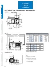
Frame NEMA Stack<br />
Diameter Frame Length<br />
42 A42 A<br />
B42 B<br />
C42 C<br />
14 143 3<br />
145 5<br />
L145 7<br />
18 182 2<br />
184 4<br />
21 213 3<br />
215 5<br />
218 8<br />
219 9<br />
25 254 4<br />
256 6<br />
259 9<br />
2512 C<br />
28 287 7<br />
288 8<br />
2810 A<br />
2812 C<br />
32 328 8<br />
3211 B<br />
3213 D<br />
50 502 2<br />
504 4<br />
506 6<br />
508 8<br />
POWER POWERTEC POWER “F” Series Motor Manual Page 3<br />
Quick Reference - - Model Numbering System - - Ferrite Motors<br />
F 2 5 4 E 1 J 0 N 0 0 1 0 0 0<br />
Motor Type<br />
F = Ferrite<br />
Stack Length<br />
4 = 254<br />
Frame Diameter<br />
25 = Nema 250<br />
Winding<br />
Connection<br />
1 = 1D<br />
2 = 2D<br />
3 = 1Y<br />
4 = 2Y<br />
Winding Letter<br />
Assigned by<br />
Factory<br />
Enclosure<br />
J = DPBV<br />
Face and Shaft<br />
0 = NEMA Foot Mount<br />
Brake<br />
N = No Brake<br />
B = 90-100V<strong>DC</strong><br />
Enclosures<br />
A TENV (IP44)<br />
B TENV (IP56)<br />
C TEFC<br />
D TEAO<br />
E TEPV<br />
F DPFG<br />
G DPSV<br />
H DPBV (w/o filter)<br />
J DPBV (w/ filter)<br />
K SPFG<br />
L TENV (washdown)<br />
M TEXP (MSHA)<br />
W TEWC<br />
X TEXP (UL)<br />
Z SPECIAL<br />
Terminations<br />
1 = Terminal Box F1<br />
2 = Terminal Box F2<br />
3 = MS Feedback F1<br />
4 = MS Feesback F2<br />
7 = Terminal Box Top<br />
8 = MS Feedback Top<br />
Primary Feedback<br />
0 = Hall Sensors<br />
2 or 5 = Resolver<br />
Bearings<br />
0 =Standard<br />
Face and Shaft<br />
0 Std Bracket and Shaft w/feet<br />
1 NEMA "C" face w/ feet<br />
2 NEMA "D" flange w/ feet<br />
3 NEMA "P" base flange<br />
4 IEC (metric) square flange w/ feet<br />
5 IEC (metric) round flange w/ feet<br />
6 NEMA "C" face w/o feet<br />
7 NEMA "D" flange w/o feet<br />
8 IEC (metric) round flange w/o feet<br />
9 Special<br />
A IEC (metric) square flange w/o feet<br />
Factory Assigned<br />
00 = All standard<br />
Secondary<br />
Feedback<br />
0 = None<br />
A = 600 PPR<br />
B = 1024 PPR<br />
Drive End Bearing<br />
0 Std Dbl Shielded Ball<br />
1 Max Capacity Ball<br />
2 Roller Bearing<br />
9 Special<br />
Primary Feedback<br />
0 Hall Switch / Thermal Switch<br />
1 Tachsyn<br />
2 Small Bore Resolver (std) / NTC's<br />
3 Optical Encoder<br />
5 Large Bore Resolver (dbl shaft) / NTC's<br />
6 No feedback<br />
7 Resolver (special) / Thermal Switches<br />
9 Special<br />
Secondary Feedback<br />
0 None<br />
A 600 PPR Optical Encoder<br />
B 1024 PPR Optical Encoder<br />
M Encoder Kit w/o encoder<br />
N Resolver, secondary<br />
L Special Encoder<br />
9 Special Feedback<br />
12/12/05 © copyright 2000 by POWER POWERTEC POWER POWER Industrial Motors, Inc.
Page 4 POWER POWERTEC POWER “F” Series Motor Manual<br />
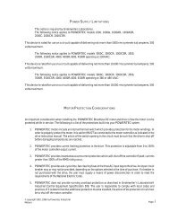
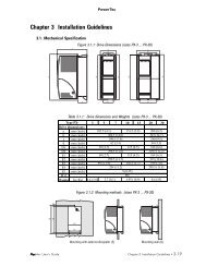
1. Key<br />
2. Rotor Assembly<br />
3. Bearing Retainer<br />
4. Bearing<br />
5. Cover Gasket<br />
6. Cover<br />
7. Hex Head Screw<br />
8. Grease Fitting<br />
9. -----<br />
10. Flat Washer<br />
11. Hex Head Screw<br />
12. Grease Fitting<br />
13. Socket Head Screw<br />
14. Encoder End Bracket<br />
15. Resolver Stator Assembly<br />
16. Set Screw<br />
17. Resolver Rotor Assembly<br />
18. Hex Washer Head Tapping Screw<br />
© copyright 2000 by POWER POWERTEC POWER Industrial Motors, Inc. 12/12/05<br />
19. Stamped Rear Cover<br />
20. Hex Head Tapping Screw<br />
21. Lifting Lug<br />
22. Drive End Bracket<br />
23. Wave Washer<br />
24. Air Baffle<br />
25. Frame/Wound Stator Assembly<br />
26. Hex Washer Head Screw<br />
27. Base<br />
28. Terminal Box Gasket<br />
29. Terminal Box<br />
30. Hex Washer Head Screw<br />
31. Cable Termination Strip<br />
32. Hex Washer Head Screw<br />
33. Terminal Strip<br />
34. Terminal Box Cover Gasket<br />
35. Terminal Box Cover<br />
36. Hex Head Tapping Screw
ELECTRICAL CONNECTIONS<br />
All connections for the motor are in the main terminal box,<br />
except on 320 frame and 500 frames. On these frames, the<br />
feedback connections are in a separate condulet box.<br />
POWER LEADS<br />
The motor ships from the factory already connected for the<br />
speed, voltage, and power listed on the nameplate. The<br />
correct connection of the motor is shown on the nameplate as<br />
"CONNECTION _ D _ Y". There will be a number “1” or<br />
“2” in front of one of these symbols.<br />
T3<br />
T1<br />
T4<br />
T7<br />
T1<br />
T10<br />
T11<br />
T12<br />
T9<br />
T6<br />
T3<br />
T8<br />
T5<br />
T2<br />
T2<br />
T3<br />
1-Y CONNECTION<br />
T1<br />
T4<br />
T6<br />
T5<br />
T2<br />
T7<br />
T10<br />
T12 T11<br />
T8<br />
T9<br />
T1<br />
T2<br />
T3<br />
POWER POWERTEC POWER “F” Series Motor Manual Page 5<br />
T12<br />
T9<br />
T6<br />
T1<br />
T4<br />
T7<br />
T11 T8 T5 T2<br />
1- CONNECTION<br />
T10<br />
T3<br />
2-Y CONNECTION 2- CONNECTION<br />
T3<br />
T6<br />
T5<br />
T1<br />
T4<br />
T2<br />
Possible motor connections.<br />
T12<br />
T9<br />
T11<br />
Whatever the motor connections, you must connect the T1<br />
motor lead to the T1 or U terminal on the motor control. You<br />
must connect the motor T2 to the T2 or V terminal on the<br />
motor control. You must connect the motor T3 to the T3 or W<br />
terminal on the motor control. Wire size must be based on the<br />
RMS current on the nameplate of the motor. The motor may<br />
draw up to 150% of this value for periods of up to one minute.<br />
In addition to the wiring of T1, T2, and T3, you must install a<br />
ground wire, which may be one size smaller than the power<br />
leads. It must run from a ground bolt in the motor's junction<br />
box to a ground bolt on the motor control. This ground wire is<br />
in addition to required grounding of the motor to its frame.<br />
Electrical connections to the motor must be tight and well<br />
insulated from each other and from the frame.<br />
NOTE: Drives with IGBT output devices generate higher<br />
voltages at the motor terminals than are normally seen with<br />
bipolar transistor types. Additional care must be taken in taping<br />
and insulating of motor leads in the motor junction box.<br />
T7<br />
T8<br />
T1<br />
T2<br />
T3<br />
T10<br />
T1<br />
T2<br />
T3<br />
<strong>MOTOR</strong> PROTECTION<br />
POWERTEC Series motors come in two types:<br />
Resolver type motors are equipped with an integral<br />
resolver mounted in the rear of the motor (non-drive end), and<br />
with two thermal switches in the windings. See page 3.<br />
Encoder type motors are equipped with a hall-effect<br />
encoder mounted in the non-drive end of the motor and a b-Imetallic<br />
thermal switch in the windings. See page 3.<br />
Thermal switches may be used in separate control circuits up<br />
to 240 VAC. Failure to connect the motor protection properly<br />
may result in damage to the motor, or drive, or both.<br />
BLOWER <strong>MOTOR</strong> CONNECTIONS<br />
Cooling blowers are supplied on DPBV and TEAO motors.<br />
Blower motor connections are located in their own box on the<br />
blower motor. Blowers will vary on non-standard motors.<br />
L1 L2 L3<br />
T1<br />
U1<br />
200-230 VAC<br />
T2 T3<br />
V1 W1<br />
T4 T5 T6<br />
U2 V2 W2<br />
SIZES 2 AND 3<br />
3 PHASE<br />
BLOWER <strong>MOTOR</strong>S<br />
L1 L2 L3<br />
12/12/05 © copyright 2000 by POWER POWERTEC POWER POWER Industrial Motors, Inc.<br />
T1<br />
U1<br />
380-460 VAC<br />
T2 T3<br />
V1 W1<br />
T4 T5 T6<br />
U2 V2 W2<br />
NUMBERS ARE PRINTED ON THE WIRES<br />
WIRE COLOR:<br />
T1 or U1 -- BLACK T5 or V2 -- WHITE<br />
T4 or U2 -- GREEN T3 or W1 -- BROWN<br />
T2 or V1 -- BLUE T6 or W2 -- YELLOW<br />
Size 2 blowers are single phase, 115VAC. These motors are<br />
impedance protected. Size 3 blowers supplied on 210T<br />
through 256T series motors are 3 phase, dual voltage design.<br />
For 200 or 230VAC input, they are connected in a delta<br />
configuration. For 380 or 460VAC operation they are<br />
connected in a star configuration. Size 8, 9, and 10 blowers<br />
use standard AC motors. They are dual voltage motors that<br />
operate on 208-230 or 460VAC. Special motors are supplied<br />
on 380VAC. Check blower motor nameplate for rating data.<br />
If starters, fuses and overloads are not supplied with a motor<br />
control, blower motors must be supplied by proper disconnect<br />
and protective devices.
Page 6 POWER POWERTEC POWER “F” Series Motor Manual<br />
RESOLVER EQUIPPED <strong>MOTOR</strong>S<br />
The resolver supplied with POWER POWERTEC POWER POWER motors is a<br />
frameless, single speed, transmitter type, mounted on the back<br />
of the motor. The rotor element is mounted on the shaft.<br />
See the table at the right for resolver specifications.<br />
R/W<br />
+ R1<br />
Excitation<br />
Winding<br />
(Primary)<br />
-<br />
R2<br />
Red<br />
Resolver Wiring Configuration<br />
S1<br />
Red<br />
Cosine<br />
Output<br />
(Secondary)<br />
S3<br />
Blk<br />
Sine<br />
Output<br />
(Secondary)<br />
- S4 Blu + S2 Yel<br />
Positive resolver rotation is CW facing the resolver end of the motor.<br />
The resolver puts out two sinusoidal waves which are in<br />
quadrature, i.e., 90° out of phase with each other. The leading<br />
wave is called the COS output (S1 and S3) and the trailing<br />
wave is called the SIN output (S2 and S4).<br />
There is one electrical cycle of each signal for each revolution<br />
of the motor. The difference between the two waves reveals<br />
the position of the motor. By looking at the period of the<br />
waveforms, the drive can determine the speed of the motor.<br />
And by looking at which waveform is leading, the drive knows<br />
in which direction the motor is turning.<br />
V T1-T2<br />
V T2-T3<br />
V T3-T1<br />
S1-S3<br />
(COSINE)<br />
S2-S4<br />
(SINE)<br />
Phasing Voltage for 8 Pole Motor<br />
for clockwise rotation at drive end<br />
1 Mechanical Revolution<br />
© copyright 2000 by POWER POWERTEC POWER Industrial Motors, Inc. 12/12/05<br />
+<br />
Resolver Output<br />
-<br />
+<br />
Primary Feedback Devices - - Technical Data<br />
Frameless Resolvers<br />
typical output @ 25°C<br />
Parameter Units R1 R2 R3<br />
Frame Size 37 49 37<br />
Type Transmitter Transmitter Transmitter<br />
Primary Rotor Rotor Rotor<br />
Speeds 1 1 1<br />
Input Voltage Vrms 8 8 6<br />
Frequency kHz 6.5 6.5 6<br />
Input Current, max mA 75 85 70<br />
Input Power, nom mW 290 510 250<br />
Transformation<br />
Ratio<br />
0.5 :1 0.5 : 1 0.333 : 1<br />
Phase Shift Deg +2 -5 -5<br />
Impedances<br />
ZRO ohms 72+j105 84+j59 82+j72<br />
ZRS ohms 82+j79 83+j59 79+j70<br />
ZSO ohms 64+j95 905+j1860 147+j247<br />
ZSS ohms 170+j355 885+j850 139+j278<br />
<strong>DC</strong> Resistances<br />
Stator ohms 52 195 28<br />
Rotor ohms 33 62 56<br />
Null Voltage mV 30 30 60<br />
Max Electrical Error minutes ±20 ±20 ±20<br />
Output Voltage Vrms 4.0 4.0 2.0<br />
Weight lb. 1.3 2.43 1<br />
NOTES:<br />
R1 resolvers are used in standard motors except as follows:<br />
R2 resolvers are used in all double shaft and TEFC 280 and<br />
320 frames and all single shaft 500 frames.<br />
R3 resolvers are used with older Control Techniques drives..<br />
Data is for estimation purposes only. For certified data, consult<br />
the factory.<br />
PHASING DIAGRAM OF <strong>MOTOR</strong> STATOR<br />
Phase T3<br />
Phase T1<br />
CW<br />
Phase T2
T10<br />
T7<br />
T4<br />
T1<br />
THERMISTORS AND THERMAL SWITCHES<br />
Motors with Resolvers have two thermal switches connected in<br />
series embedded in the windings.<br />
Millenium Motors equipped with R1 and R2 Resolvers have<br />
two Negative Temperature Coefficient (NTC) thermistor<br />
probes. They are 10,000 ohms each @ 25°C, connected in<br />
parallel to terminals 8 and 9 in the motor junction box.<br />
Thermistor leads are labeled P1 and P2. At Room temperature<br />
(25°C) the resistance between P1 and P2 should be 5000<br />
ohms.<br />
The Overtemperature threshold for totally enclosed motors is<br />
145°C (104.2 0hms). The threshold for drip proof and blower<br />
ventilated motors is 130°C (150.5 ohms).<br />
Since the potential exists for a thermistor to open up, Motor<br />
Overtemperature Warnings should be set no higher than 80%<br />
of Fault Temperature on totally enclosed motors, and no<br />
higher than 80% for drip proof and blower ventilated motors.<br />
POWER POWERTEC POWER “F” Series Motor Manual Page 7<br />
RESOLVER <strong>MOTOR</strong>S - - CONNECTIONS AND TERMINAL MARKINGS<br />
<strong>MOTOR</strong><br />
T11<br />
T8<br />
T5<br />
T2<br />
T12<br />
T9<br />
T6<br />
T3<br />
CASE<br />
GROUND<br />
S1<br />
RED<br />
S3<br />
BLK<br />
1 2<br />
RESOLVER THERMAL DEVICES<br />
S2<br />
YEL<br />
S4<br />
BLU<br />
3 4<br />
SHIELDS<br />
R1<br />
RED/WHT<br />
R2<br />
BLK/WHT<br />
P1<br />
5 6 7<br />
THERMAL<br />
SENSOR<br />
<strong>MOTOR</strong> / RESOLVER LEADS<br />
Motors are shipped with nameplate connections (i.e., 1-Y, 1-D, 2Y, or 2-D)<br />
Check Motor nameplate for correct connections.<br />
See page 4 for connection diagrams.<br />
Consult drive manual for motor / drive interconnections.<br />
P2<br />
8 9 10<br />
SPACE HEATERS<br />
When supplied, will have leads tagged H1 and H2. Check nameplate for voltage and current ratings.<br />
OTHER ACCESSORIES<br />
Check motor nameplate and accessories nameplates for connections and ratings.<br />
CAUTION :<br />
Connect cable shields to designated points only. DO NOT connect shields to ground.<br />
Millenium Thermistor Resistance Table<br />
Nominal Resistance between P1 and P2 in ohms<br />
Resistance tolerance is +/- 5%<br />
Winding<br />
Temp.<br />
RP1-P2 Winding<br />
Temp.<br />
RP1-P2<br />
°C ohms °C ohms<br />
-30 88500 90 459<br />
-20 48535 100 340<br />
-10 27665 110 255.5<br />
0 16325 120 194.5<br />
10 9950 130 150.5<br />
20 6250 140 117.5<br />
30 4028 150 92.5<br />
40 2663 160 74<br />
50 1801 170 59.5<br />
60 1244 180 48.5<br />
70 876 190 39.7<br />
80 629 200 32.8<br />
12/12/05 © copyright 2000 by POWER POWERTEC POWER POWER Industrial Motors, Inc.<br />
NC
Page 8 POWER POWERTEC POWER “F” Series Motor Manual<br />
ENCODER EQUIPPED <strong>MOTOR</strong>S<br />
The encoder connections must be run in a shielded cable.<br />
There are seven connections to the encoder. When the motor<br />
thermal is run in the 24V<strong>DC</strong> or 48V<strong>DC</strong> control circuit, it may<br />
also be run in the cable (except on the 320 frame motors<br />
where the thermal connections are not in the same junction<br />
box). A cable such as BELDEN ® part #9539 may be used.<br />
A connection diagram is supplied with each motor control. The<br />
shield should be connected at the drive end at TB1 terminal 1.<br />
The shield on the motor end should be connected to the<br />
terminal strip in the motor at terminal 10. DO NOT GROUND<br />
THE SHIELD AT ANY POINT. If there are junction boxes<br />
between the motor and the control, install a terminal to<br />
continue the shield through the junction box.<br />
ENCODER ALIGNMENT PROCEDURE<br />
If a motor has been disassembled, the encoder must be lined<br />
up again so that it is properly aligned with the magnets on the<br />
rotor and the windings of the stator. Also, if the encoder has<br />
been replaced, adjustment of the assembly is necessary.<br />
There are two types of feedback assemblies. F1 encoders are<br />
used for motors with the junction boxes mounted on the left<br />
side of the motor (facing the drive end with the feet down) and<br />
for motors with junction boxes on the right side of the motor<br />
near the back. A top mounted box uses the F1 assembly.<br />
F2 assemblies are for older motors motors with the junction<br />
box on the right side of the motor near the drive end. These<br />
encoders are for replacement use only.<br />
PROCEDURE<br />
1. The encoder feedback assembly mounts in the back of<br />
the motor. The hole in the end bell on the junction box side<br />
locates the cable breakout point from the feedback assembly.<br />
An end bell mark shows the notch location.<br />
2. After the feedback assembly is mounted, but before the<br />
© copyright 2000 by POWER POWERTEC POWER Industrial Motors, Inc. 12/12/05<br />
magnetic wheel is mounted on the shaft of the rotor, it is<br />
necessary to align the rotor with the stator. The connections on<br />
the power leads must be made according to the nameplate<br />
(see Page 3). Start with the keyway of the motor shaft in the 12<br />
o'clock position (up) with the motor standing on its feet.<br />
3. The alignment of the rotor may be done on small motors<br />
by attaching any battery (such as a 9 volt cell) to the power<br />
leads. The positive terminal should be connected to the T1<br />
lead of the motor, and the negative terminal of the battery<br />
should be connected to the T2 lead of the motor. The rotor will<br />
move to the nearest pole. Do not leave the battery connected<br />
or it will quickly be drained.<br />
On larger motors, the Genesis Series motor control may be<br />
used to align the rotor. Turn off the motor control and turn the<br />
current limit (both current limits on a regenerative drive)<br />
potentiometer(s) fully counter-clockwise. Disconnect the wires<br />
on the motor control at TB1 terminals 2,3, and 4. Connect a<br />
jumper wire from TB1 terminal 16 to TB1 terminal 3 on the<br />
motor control. Turn on the motor control, give it a speed<br />
command of about 10%, and turn the current limit (motoring)<br />
up about 30°. The motor will align to the nearest pole. Return<br />
the motor control to its proper connections and adjustments.<br />
With an LED box or meter on the diode scale, put the encoder<br />
wheel on the shaft with the white mark near the cable breakout<br />
and turn the wheel on the shaft to obtain the following results<br />
(on the meter, an on sensor will have a low impedance):<br />
F1 Junction Box F2 Junction Box (old motors)<br />
HS1 ON OFF<br />
HS2 OFF ON<br />
HS3 Changing Changing<br />
When this condition is obtained, fasten down the encoder<br />
magnetic wheel on the shaft with the two set screws (90°<br />
apart) on the hub. The motor should now be aligned within 3°<br />
of its rotation to the stator.
SETTING NEUTRAL<br />
The preceding procedure is used at the factory to do the<br />
initial setting of the encoder alignment. Then factory alignment<br />
marks are placed on the end bell for the position of the notch<br />
on the feedback assembly, and on the motor shaft and<br />
encoder magnetic wheel to show the alignment of the encoder<br />
parts. The previous procedure can be bypassed if the factory<br />
marks are plainly evident and the motor has not been<br />
rewound.<br />
Installing a new encoder on the motor or reinstalling the<br />
old one may be done by the factory marks as long as the<br />
motor is properly assembled. Then it is necessary to set the<br />
actual position of the feedback assembly to set the neutral of<br />
the encoder. This is the fine tuning of the encoder alignment.<br />
PROCEDURE<br />
Connect a true RMS AC voltmeter to motor leads T1 and<br />
T2. Do not use a peak-reading meter.<br />
Run the motor with no load at rated RPM in the forward<br />
direction and note the AC voltage level on the meter.<br />
3. Run the motor in the reverse direction at rated RPM<br />
and note the voltage on the meter.<br />
Adjust the feedback assembly (by loosening the two<br />
mounting screws) a few degrees left or right to equalize the AC<br />
voltage in both directions within one percent.<br />
POWER POWERTEC POWER “F” Series Motor Manual Page 9<br />
<strong>MOTOR</strong> THERMAL SWITCH<br />
-- There is a motor temperature thermal switch in the<br />
motor, inserted in the stator windings. The motor thermal<br />
switch leads are located in the main junction box. THIS<br />
<strong>MOTOR</strong> THERMAL SWITCH MUST BE USED TO<br />
PROPERLY PROTECT THE <strong>MOTOR</strong>! Failure to use this<br />
switch may result in the destruction of the motor. Brushless <strong>DC</strong><br />
motor thermal switches work better than their brush-type <strong>DC</strong><br />
motor counterparts because the heat in a Brushless <strong>DC</strong> motor<br />
is produced in the stator, where the switch is located.<br />
The motor thermal switch is rated as follows:<br />
MAX AMPS BREAK: 12 amps @ 120VAC<br />
8 amps @ 240VAC<br />
2 amps @ 24V<strong>DC</strong><br />
CONTINUOUS AMPS: 2 amps at all voltages above.<br />
12/12/05 © copyright 2000 by POWER POWERTEC POWER POWER Industrial Motors, Inc.
Page 10 POWER POWERTEC POWER “F” Series Motor Manual<br />
<strong>MOTOR</strong> ENCLOSURES<br />
The enclosure type is determined by whether the motor is<br />
cooled by air moving through it, or by convection to the<br />
ambient air around it, or by air moving over it. CONSTANT<br />
TORQUE SPEED RANGE (CTSR) is a thermal consideration.<br />
The constant torque speed range is the range of speeds<br />
(based on base speed) over which the motor will run at full<br />
load without overheating or de-rating. De-rating the motor<br />
beyond its speed range does not mean it will not put out full<br />
torque. It means the motor cannot thermally support full torque<br />
output continuously.<br />
DPFG -- DRIP PROOF, FULLY GUARDED<br />
The drip proof, fully guarded motor moves air through the<br />
motor by means of an internal, shaft driven fan. Louvered<br />
covers in the front and rear of the motor prevent foreign matter<br />
from entering the motor when dropped from above or at an<br />
angle of up to 18° from the vertical. The Constant Torque<br />
Speed Range of the DPFG motor may be 2:1 or 100: 1,<br />
depending upon the frame size.<br />
DPBV -- DRIP PROOF, BLOWER VENTILATED<br />
The drip proof, blower ventilated motor uses forced air through<br />
the motor to cool it. The blower is generally mounted at the<br />
rear of the motor (at the non-drive end) and the forced air is<br />
exhausted out the front of the motor. The blower is separately<br />
powered. The CTSR is normally 100:1 or better.<br />
TENV -- TOTALLY ENCLOSED, NON-VENTILATED<br />
The totally enclosed non-ventilated motor is dust-tight with no<br />
openings to the ambient air. The motor is cooled by natural<br />
convection and radiation. The CTSR of the TENV motor is<br />
100:1 or greater, but the horsepower range is limited to smaller<br />
sizes.<br />
TEFC -- TOTALLY ENCLOSED, FAN COOLED<br />
The totally enclosed fan cooled motor is dust-tight with no<br />
openings to ambient air. A shaft-mounted fan on the non-drive<br />
end of the motor cools the motor. This allows higher<br />
horsepowers than TENV. The CTSR of TEFC motor is 2:1.<br />
TEAO -- TOTALLY ENCLOSED, AIR OVER, OR<br />
TEBC – TOTALLY ENCLOSED, BLOWER COOLED<br />
If a totally enclosed applications requires a wider speed range<br />
and larger horsepowers, the totally enclosed, air over (blower<br />
cooled) motor has a constant speed fan, which blows air over<br />
the motor’s external surface to cool it. Since the air volume is<br />
constant with speed, the Constant Torque Speed Range of the<br />
TEAO motor is 100:1.<br />
© copyright 2000 by POWER POWERTEC POWER Industrial Motors, Inc. 12/12/05<br />
TEWC -- TOTALLY ENCLOSED, WATER COOLED<br />
For still larger sizes of totally enclosed motors, the totally<br />
enclosed, water cooled motor removes heat by means of a<br />
water jacket. Cooling water, or other liquid, may be used in a<br />
closed or open system. The CTSR is 100:1 or greater.<br />
This list is not a complete listing of all types, nor is the<br />
description complete. For further information on motor<br />
enclosures, consult NEMA Publication No. MG1.<br />
<strong>MOTOR</strong> COOLING REQUIREMENTS<br />
FORCED AIR COOLING<br />
DPBV and TEAO motors require forced-air cooling, which is<br />
accomplished by a centrifugal blower and AC motor.<br />
Separately Ventilated motors (DPSV) require the user to<br />
supply a forced air stream to cool the motor. Whether supplied<br />
by POWER POWERTEC POWER or others, the cooling blowers must have<br />
minimum specifications as follows:<br />
AIRFLOW STATIC BLOWER<br />
FRAME CFM PRESSURE SIZE<br />
182T,184T 100<br />
inches of water<br />
0.9 2<br />
213T,215T 200 1.9 3<br />
254T,256T 223 1.6 3<br />
259T 270 2.6 8<br />
287T,288T,2810T,2812T 425 4.6 9<br />
328T,3211T,3213T 660 4.0 10<br />
504ATZ, 506ATZ,508ATZ 1500 1.1 12<br />
Check the motor blower nameplate for the voltage and current<br />
requirements of your blower..<br />
WATER COOLING<br />
Cooling water for TEWC motors must enter the motor at no<br />
more than 40 °C. To maintain a maximum temperature at the<br />
water outlet of 55 °C, the following minimum flow rates must<br />
be maintained for each frame size listed:<br />
FRAME FLOW RATE (GPM)<br />
254T 0.8<br />
256T 1.3<br />
259TZ 1.7<br />
288TZ 1.8<br />
2810TZ 2.2<br />
2812TZ 2.7<br />
326TZ 2.8<br />
328TZ 3.4<br />
3211TZ 4.0<br />
Other cooling liquids and/or additives may be used.<br />
Consult the factory for the required flow rates.
<strong>MOTOR</strong> SERVICE PROCEDURE<br />
Any competent motor shop that can overhaul AC induction<br />
motors may service Brushless <strong>DC</strong> motors. There are<br />
differences that must be observed in the permanent magnet<br />
rotor, the feedback, and the bearings.<br />
PERMANENT MAGNET ROTOR - Permanent magnets used<br />
in the Brushless <strong>DC</strong> motor are constructed of a highly stable<br />
material and will not demagnetize under normal conditions.<br />
The motors can be disassembled and reas-sembled without<br />
affecting the strength of the magnets.<br />
HANDLE THE ROTOR WITH GREAT CARE SINCE THE<br />
MAGNETS ARE BRITTLE AND CAN BE DAMAGED IF<br />
DROPPED! DO NOT SET ON A STEEL SURFACE!<br />
RESOLVER - The resolver consists of two parts: a rotor<br />
mounted on the shaft and the stator attached to the motor's<br />
end bell at the non-drive end. These components must line up<br />
properly if the motor is to operate correctly. See page 8 for the<br />
encoder alignment procedure after re-assembling an encoder<br />
equipped motor.<br />
BEARINGS -- Bearings are press-fit on the rotor shaft. The<br />
rear (non-drive end) bearing is fixed in place by a bearing<br />
retainer plate, and both bearings are slip fit into their housings.<br />
When replacing bearings, they must be positioned up against<br />
the bearing shoulder on the shaft.<br />
DIS-ASSEMBLY OF THE <strong>MOTOR</strong><br />
Refer to exploded view drawing and parts list on page 4. This<br />
is a general drawing, and not all details are shown.<br />
1. Before disassembling the motor, remove the rear<br />
cover (#19) from the bracket (# 14) to expose the resolver.<br />
2. Make sure that there are marks on the end bells<br />
(#14 and #22), frame (#25), resolver assembly (#15), resolver<br />
rotor (#17), and motor shaft (#2) to locate parts when the<br />
motor is reassembled. Be sure those marks will not be<br />
obscured in the process.<br />
3. Remove the resolver rotor (#17) from the shaft. It is<br />
secured by two set screws (#16) 90° apart on the hub.<br />
4. Remove the two bearing retainer plate screws (#13)<br />
in the non-drive end. In some cases this may require loosening<br />
the two set screws (#18) holding the resolver assembly (#15)<br />
and moving the resolver stator out of the way. This releases<br />
rear bearing (#4) and allows removal of the shaft or end bell.<br />
5. Remove four bolts (#11) that hold the drive end<br />
bracket (#22) on. Some motors have hex nuts on overbolts<br />
that run the length of the motor. Note the location of the lifting<br />
lugs (#21).<br />
6. Carefully slide the drive end bracket (#22) off of the<br />
shaft (#2). Don't allow the end bell to scrape the shaft as it is<br />
POWER POWERTEC POWER “F” Series Motor Manual Page 11<br />
removed. Note carefully the location of parts that come loose<br />
as the end bell is removed, such as the wave washer (#23) in<br />
the front housing. The rotor stays in the frame assembly.<br />
7. The rotor (#2) may now be removed by sliding it<br />
slowly out. The banding will protect the magnets against<br />
damage while sliding out straight. Avoid jerky side to side<br />
movements. While the rotor is out of the motor, protect the<br />
banding and magnets from sharp blows and pointed objects.<br />
8. If only the rotor assembly is to be serviced, it is not<br />
necessary to remove the resolver end bracket (#14). If the<br />
motor stator is to be rewound, then the resolver end bracket<br />
should be removed. Remove the two set screws (#18) holding<br />
the resolver (#15) in place. Before removing the resolver,<br />
disconnect the wires from the block (#31) in the motor junction<br />
box and tie a string onto the wires. This will help cable<br />
reinstallation. Remove the assembly.<br />
DO NOT PULL ON THE WIRES OF THE CABLE OR ON<br />
THE ASSEMBLY. Pull the outside cable jacket only.<br />
RE-ASSEMBLY OF THE <strong>MOTOR</strong><br />
1. Make sure the inside surface of the stator is smooth<br />
with no foreign material (such as metal shavings) in the area.<br />
Also check rotor assembly for foreign matter (like metals).<br />
2. Carefully slide the rotor (#2) into the stator assembly<br />
(#25) slowly, BEING VERY CAREFUL TO AVOID INJURY TO<br />
THE HANDS OR ARMS. Make sure you insert the rotor from<br />
the drive end of the frame.<br />
3. Once the rotor is inside the stator assembly, the<br />
resolver end bracket (#14) may be installed. Make sure the<br />
marks made before disassembly line up properly. Use long<br />
screws to position the bearing retainer plate before pushing<br />
end bell in. Replace bearing retainer plate screws (#13).<br />
4. Position the air baffle (#24 - not TENV motors), and<br />
place the wave washer (#23) in position in the front housing.<br />
Replace drive end bracket (#22) according to the marks made<br />
before disassembly, being careful not to scratch the shaft.<br />
5. Reinsert four bolts (#11) into holes in the end bells of<br />
the motor (don't forget the lifting lugs - #21), making sure the<br />
end bells are seated properly in the ends of the frame.<br />
6. Install the resolver (#15) according to the orientation<br />
marks and connect cable leads to the block in the junction box<br />
(#31) according to the drawing on page 7.<br />
7. Reinstall rotor (#17) on the shaft by the marks.<br />
8. Turn the motor by hand to check for rubbing,<br />
scraping, and make sure the shaft turns freely. Check for<br />
lengthwise and sideways movement of the shaft.<br />
9. Torque down all bolts and screws, and proceed to<br />
motor resolver alignment or motor encoder alignment.<br />
12/12/05 © copyright 2000 by POWER POWERTEC POWER POWER Industrial Motors, Inc.
Page 12 POWER POWERTEC POWER “F” Series Motor Manual<br />
TROUBLESHOOTING<br />
When a motor does not operate as expected, there<br />
may be a valid reason other than that the motor is<br />
bad. Troubleshooting involves looking at the<br />
entire system of motor, control and<br />
environment. Problems that occur when a motor is<br />
first put into service are most likely caused by<br />
misapplication, improper connection or lack of<br />
understanding. Problems that occur after a motor<br />
has been in service for some time period may be<br />
due to motor, control or environment.<br />
These troubleshooting tips cover possible problems<br />
as well as problems which were seen in the past.<br />
PROBLEM SHAFT ROCKS BACK AND FORTH<br />
1. Motor leads T1, T2, and T3 are not connected to the<br />
corresponding terminals on the motor control. T1 MUST be connected to T1,<br />
T2 MUST be connected to and T3 MUST be connected to T3.<br />
2. Encoder cable is connected to control improperly. Check the<br />
connections to the control per the card supplied with the control. The main<br />
connections involved are the connections involving HS1, HS2, and HS3.<br />
PROBLEM ERRATIC SPEED<br />
1. Motor is going at or above base speed while cold. Allow motor to<br />
warm up before adjusting maximum speed.<br />
2. Encoder cable from motor to control is improperly shielded, run<br />
with power cables, or defective. Check the cable connections per the card<br />
supplied with the control.<br />
3. Encoder signals are improper or missing. Check waveforms<br />
against drawing below. The drawing below is for a four pole motor. An eight<br />
pole motor will have the same waveforms, but the interval marked as being<br />
1/2 revolution of the motor in the drawing below will be 1/4 revolution in an<br />
eight pole motor.<br />
4. Bearings are worn. This will likely show up as increased current<br />
and an overheating motor, but severe bearing problems may affect speed<br />
control of the drive.<br />
5. Severe load variations, such as a high inertia load changing<br />
speeds quickly may result in speed being erratic. Consult Pacific Scientific.<br />
6. Drive is unstable. Adjust gain and/or stability<br />
Encoder waveforms<br />
OFF<br />
ON<br />
OFF<br />
ON<br />
OFF<br />
ON<br />
OFF<br />
ON<br />
OFF<br />
ON<br />
© copyright 2000 by POWER POWERTEC POWER Industrial Motors, Inc. 12/12/05<br />
PROBLEM EXCESS END PLAY OF THE SHAFT<br />
Check for excessive thrust loading on the shaft.<br />
1. Check the tightness of the bearing retainer plate by checking the<br />
bearing retainer plate screws on the non-drive end. (On some motors, these<br />
screws may be partially or completely hidden by the feedback assembly.)<br />
2. The bearings may be excessively worn.<br />
3. The shaft bearing journals may be shot.<br />
PROBLEM EXCESS RADIAL SHAFT PLAY<br />
* Make sure radial loading on shaft is not excessive.<br />
1. The shaft may be loose in the bearing I.D.<br />
2. There may be excessively worn bearings.<br />
3. The bearing housing may be worn.<br />
PROBLEM EXCESS VIBRATION<br />
1. The load may be out of balance. Check the load balance.<br />
2. The motor mounting bolts may be loose. Check for tightness.<br />
3. The rotor may be unbalanced. Run the motor unloaded.<br />
4. There may be excessive radial play. See above.<br />
5. The bearings may be worn. Listen for bearing noise.<br />
6. Noise on drive speed reference.<br />
PROBLEM <strong>MOTOR</strong> RUNS HOT LOADED<br />
DO NOT JUDGE <strong>MOTOR</strong> TEMPERATURE BY TOUCH.<br />
USE A TEMPERATURE MEASURING DEVICE.<br />
1. Check ambient temperature. It must be less than rated (40°C).<br />
2. Check the load on the motor. Do not exceed rated current.<br />
3. Check the duty cycle of the motor. It may not exceed 100% RMS.<br />
4. The brake, if there is one, may not be releasing.<br />
5. The bearings may be worn. Run motor unloaded.<br />
6. The rotor may be rubbing the stator. Listen for noise.<br />
PROBLEM <strong>MOTOR</strong> RUNS HOT UNLOADED<br />
1. Check all items under Motor runs hot loaded.<br />
2. The motor control may be misadjusted. Check motor control.<br />
3. The encoder may be improperly set up. See Page 6.<br />
4. The motor may be demagnetized. Check terminal voltages.<br />
PROBLEM <strong>MOTOR</strong> RUNS TOO FAST<br />
1. Check the maximum speed setting on the motor control.<br />
2. HS4 and HS5 on the encoder signals may be swapped.<br />
3. Resolver or encoder misaligned.<br />
4. Motor may be demagnetized. Check terminal voltages.<br />
PROBLEM LOW OUTPUT TORQUE<br />
1. Improper alignment of feedback device<br />
2. Open power connection.<br />
3. Open or shorted stator windings.<br />
4. Motor may be partially demagnetized.
ROUTINE MAINTENANCE<br />
Observe the motor during operation, checking for excess<br />
vibration, unusual noises and excess heat.<br />
1. VIBRATION<br />
1. Check for signs of excess vibration. It may be the result<br />
of poor alignment, worn or loose couplings or sheaves, or<br />
damaged bearings. It may be a poorly designed base. Excess<br />
vibration causes damage to the bearings, shaft, mounting feet<br />
and accessories.<br />
2. Noise on the speed reference input to high performance<br />
drives has been known to cause vibration in motors.<br />
3. When checking balance on an unloaded motor, install a<br />
half key in the shaft keyway..<br />
2. NOISE<br />
1. Listen for noise in the area of the bearing housings.<br />
Rubbing noises may be a sign of internal damage.<br />
2. A steady high pitched hum is normal in a BL<strong>DC</strong> motor,<br />
and there may be short interruptions of this hum under no load<br />
conditions. If you hear growling or an erratic hum above 20<br />
RPM, check the drive.<br />
3. TEMPERATURE<br />
1. Drip Proof Fully Guarded (DPFG), Drip Proof Blower<br />
Ventilated (DPBV), and Totally Enclosed Air Over (TEAO)<br />
motors may run at surface temperatures in excess of 85°C.<br />
2. Totally Enclosed motors (TENV) may have surface<br />
readings as high as 100 °C. Before checking the temperature<br />
of a motor, check the load on the motor.<br />
Use a thermal probe for an objective reading<br />
DO NOT CHECK <strong>MOTOR</strong> TEMPERATURE WITH YOUR BARE<br />
HAND!!! HIGH TEMPERATURES MAY CAUSE BURNS!<br />
4. FEEDBACK DEVICE<br />
1. The feedback device is located inside the motor. It<br />
requires no maintenance unless you disassemble the motor.<br />
2. The alignment of the motor feedback device is important.<br />
If it is removed, it must be re-installed correctly.<br />
5. BRAKES<br />
1. Brakes supplied on "F" series Brushless <strong>DC</strong> motors are<br />
fail-safe, disk type brakes. You release the brake by energizing<br />
the brake coil. There may be a manual release.<br />
2. The brakes do not normally require adjustments, but the<br />
pads may have to be changed periodically if the brake is used<br />
for stopping duty.<br />
POWER POWERTEC POWER “F” Series Motor Manual Page 13<br />
6. SECONDARY FEEDBACK DEVICE<br />
Check externally mounted encoders (coupling and mounting<br />
bolts) periodically for tightness.<br />
7. COOLING BLOWERS AND FILTERS<br />
Cooling blowers are AC motors that require little maintenance.<br />
They have a lubrication life of 15,000 to 40,000 hours.<br />
ATTEMPTING TO SERVICE THE FILTER WHILE THE<br />
BLOWER <strong>MOTOR</strong> IS RUNNING MAY CAUSE INJURY.<br />
1. Be sure the blower is running in the correct direction,<br />
which is in the direction of the arrow on the blower scroll.<br />
2. Clean out multi-crimp filters with a solvent. Let dry<br />
thoroughly. Spray with an air filter adhesive and drain excess.<br />
3. Before re-mounting the filter, be sure that there is no<br />
build-up of material inside or on the blades of the impeller.<br />
8. BEARINGS AND RE-LUBRICATION<br />
1. 42, 140, and 180 frame motors have permanently<br />
lubricated bearings. Replace damaged or worn bearings.<br />
2. Frames 210 and larger are lubricated at the factory with<br />
Mobil Polyrex EM. Suitable substitutes are Amoco’s RYKON<br />
Premium #2, Texaco's Polystar B, Chevron SRI #2 grease, or<br />
EXXON’s Polyrex. Do not use the “EP” versions of these<br />
greases. High-speed motors use Mobil SHC15.<br />
3. Use the table below for bearings of standard motors with<br />
standard or maximum capacity bearings. These motors have a<br />
"0" or "1" as the 10th digit in the Model Number. Re-lubricate<br />
vertically mounted motors at 1/2 the table interval.<br />
4. Roller bearings are indicated by a "2" in the tenth<br />
position of the Model Number. Re-lubricate these at 1/2 of the<br />
table interval. For vertically mounted motors, use ¼ of the<br />
interval. For high speed motors, consult the graph on page 16.<br />
High-speed motors have a "9" in the tenth position.<br />
Lubrication Interval in Operating Hours - STANDARD BALL BEARINGS only<br />
HORIZONTALLY MOUNTED, AVERAGE <strong>MOTOR</strong> SPEED (in<br />
FRAME 1150 1750 2500 3600<br />
42 28,000 18,000 13,000 8,500<br />
140 23,000 14,000 10,000 6,700<br />
180 19,000 12,000 8,000 5,400<br />
210 16,000 10,000 6,300 3,800<br />
250 13,500 8,000 5,000 2,900<br />
280 11,500 6,600 3,900 2,200<br />
320 9,600 5,600 3,000 1,400<br />
500 6,400 3,200 500 N/A<br />
If a motor has no grease fittings, the bearings must be replaced.<br />
12/12/05 © copyright 2000 by POWER POWERTEC POWER POWER Industrial Motors, Inc.
Page 14 POWER POWERTEC POWER “F” Series Motor Manual<br />
MOUNTING BOLT TORQUES<br />
Motors must be mounted on a solid, rigid base or foundation.<br />
Poor base design can result in resonance in the motor/base<br />
system that can result in bearing, motor feet, frame to foot<br />
fasteners, or other, motor damage.<br />
All hold-down bolts must be of the correct grade for the type of<br />
mounting, and for the method of coupling the motor to the<br />
load. Some considerations are:<br />
1. Direct coupled or belt drives<br />
2. Motor feet orientation (horizontal, wall, or cieling<br />
mounting).<br />
Bolts must be evenly torqued to their recommended value.<br />
Recommended bolt torques for SAE grade foot bolts are given<br />
below in foot-pounds. (All components are dry, i.e., not<br />
lubricated):<br />
Foot Bolt Steel Steel<br />
Frame Hole Size Grade Grade Socket<br />
Size Diam & Thrd 1 5 Head<br />
42 .34 5/16-18 10 15 25<br />
140 .34 5/16-18 10 15 25<br />
180 .41 3/8-16 16 26 42<br />
210 .41 3/8-16 16 26 42<br />
250 .53 1/2-13 39 63 100<br />
280 .53 1/2-13 39 63 100<br />
320 .69 5/8-11 77 125 200<br />
500 1.19 1-8 320 500 820<br />
Motors with aluminum feet require a suitable heavy flat steel<br />
washer between the foot and the mounting fasteners to spread<br />
the bolt-clamping load out over a suitable area.<br />
The above values are suitable for most applications. Heavily<br />
loaded systems, and systems that are dynamic may require<br />
careful study in choosing a suitable mounting system, grade of<br />
bolt to be used, and hence the required bolt torques.<br />
© copyright 2000 by POWER POWERTEC POWER Industrial Motors, Inc. 12/12/05<br />
RADIAL LOADING OF THE <strong>MOTOR</strong><br />
When a motor is driving a belt-driven load, care must be taken<br />
to prevent the side pulling forces to damage the bearings<br />
and/or the shaft of the motor.<br />
MAXIMUM SHAFT RADIAL LOADING<br />
Standard Ball Bearings and standard shaft extension<br />
Radial Load Centered at tip of<br />
Expected L10 life at 1750 RPM average speed of 20,000 hours<br />
Frame/ Series Shaft Diam Bearing #<br />
Max Radial Load<br />
(lbs.)<br />
Min Sheave Dia<br />
(in.)<br />
42 0.625 203 90 0.9<br />
140 .875 205 180 2.4<br />
182/184 1.125 207 280 4.6<br />
213/215 1.375 209 440 4.4<br />
219 1.625 209 650 4.0<br />
254/256 1.625 211 600 6.5<br />
259/2512 2.125 M211 1100 6.0<br />
287 2.125 313 1100 6.0<br />
288/2810/281 2.375 313 1350 9.6<br />
328/3211/321 2.875 315 1800 12.0<br />
504 3.25 6222 / 6222W 1500 / 2200 21.6 / 14.7<br />
506 3.625 6222 / 6222W 1400 / 2100 30.9 / 20.6<br />
508 4.125 6222 / 6222W 1300 / 2000 41.5 / 27.0<br />
If radial loads exceed the "Max Radial Load", or the sheave diameter is too<br />
small, contact the factory for assistance.<br />
500 frames with ball bearings are recommended for direct coupled service only<br />
Belt drives with 500 frame motors require roller bearings in the drive end.
<strong>MOTOR</strong> NAMEPLATE DATA<br />
FRAME<br />
An alphanumeric designation of the size of a motor. These<br />
designations are standardized in the USA by the National Electrical<br />
Manufacturers Association (NEMA). For standard NEMA frames140<br />
and larger, the first two numbers are four times the height of the<br />
center of the motor shaft above the feet. The third and fourth (if used)<br />
numbers indicate the distance between the mounting holes on the feet<br />
lengthwise, but a table is necessary to find the actual distance.<br />
MODEL<br />
The MODEL number of the "F" series motors is a description of how<br />
the motor is put together. The model number describes the windings<br />
and connections as well as frame size, configuration, and options.<br />
HP<br />
The rated output horsepower of the motor is listed in the HP block.<br />
This value of horsepower is only valid at base speed, or above base<br />
speed, if the drive is equipped to operate in extended speed range.<br />
RPM<br />
The base speed of the motor, the speed at which rated horsepower is<br />
developed. From zero to this speed is the CONSTANT TORQUE<br />
speed range. If there are two numbers in this block with a slash<br />
between them, the first number is the base speed and the second<br />
number is the top speed. Between these two speeds is the<br />
CONSTANT HORSEPOWER range.<br />
BUS V<strong>DC</strong><br />
For a Brushless <strong>DC</strong> motor, this is the voltage level of the <strong>DC</strong> supply<br />
from which the drive operates the motor. In most cases, this value is<br />
the nominal capacitor bank voltage level, which is about 1.4 times the<br />
RMS value of the AC input to the drive.<br />
DUTY<br />
This is a rating which may limit how the motor is used. If the<br />
designation CONT is in this block, the motor may be used for<br />
continuous duty up to its full ratings. A 30 MIN rating in the DUTY<br />
block indicates that the motor may be run to its full rating for 30<br />
minutes, after which it must cool to ambient temperature.<br />
RMS AMPS<br />
This is the per phase motor current (in RMS AC amperes ) required<br />
to develop full load torque on a motor that has reached its steady<br />
state operating temperature.<br />
S.F.<br />
The SERVICE FACTOR is a multiplier to the HP, indicating how much<br />
power may be used under rated conditions.<br />
POWER POWERTEC POWER “F” Series Motor Manual Page 15<br />
INSUL. CL.<br />
INSULATION CLASS "F" is rated for 105°C rise above an ambient<br />
temperature of 40°C. Class "H" is rated for 125°C rise. The motor<br />
over- temperature protector is set to correspond.<br />
AMB °C<br />
The AMBIENT TEMPERATURE in which the motor operates should<br />
not exceed this number.<br />
ENCL<br />
This is the type of enclosure of the motor. In Europe, it is called the<br />
PROTECTION CLASS. There are two basic types: OPEN and<br />
CLOSED. See "<strong>MOTOR</strong> ENCLOSURES" on page 6 for a description<br />
of the standard NEMA motor enclosures.<br />
C.T. SPD. RANGE<br />
This is the ratio of speeds, based on BASE SPEED, over which the<br />
motor may be operated at full torque continuously. This is a<br />
THERMAL limitation. This does not guarantee smooth operation, only<br />
that the motor is able to cool itself at full torque over this range.<br />
CONNECTION<br />
This is either 1-D or 2-D, 1-Y or2-Y. (D = delta; Y = wye) This refers<br />
to the connection of the windings. See "Motor Winding Connections"<br />
for details on the connections.<br />
PEAK RMS AMPS<br />
Do not exceed this value at any time. This is the maximum safe<br />
current which will not affect the permanent magnets.<br />
INTEGRAL ENCODER<br />
This number is the pulses per revolution (PPR) which will be seen in<br />
one channel of the speed feedback (HS4 or HS5) from the internal<br />
encoder. The two channels are 90° out of phase with each other, i.e.,<br />
they are in QUADRATURE. For small motors the number should<br />
be 30. Large motors should be 60.<br />
KE V/KRPM<br />
This is the RMS voltage which should be observed between any two<br />
power leads of the motor at 1000 RPM. This measurement is taken<br />
with the windings at room temperature (25 °C). Actual voltage at<br />
operating temperature may be as low as 90% of the 25 °C value.<br />
SERIAL NO.<br />
Use when calling to ask questions or to order spare parts. This<br />
number is also stamped into the frame near the junction box.<br />
JOB NO.<br />
This is a factory in-house number for the factory build job that<br />
included this motor.<br />
12/12/05 © copyright 2000 by POWER POWERTEC POWER POWER Industrial Motors, Inc.
Page 16 POWER POWERTEC POWER “F” Series Motor Manual<br />
BEARING RELUBRICATION INTERVAL CHART<br />
USE SE SE THIS THIS CHART CHART TO TO EST ESTIMATE EST IMATE THE THE RELUBRICAT<br />
RELUBRICATION RELUBRICAT ION INTERVAL INTERVAL AT AT SPEEDS SPEE<br />
SPEEDS<br />
DS OTHER OTHER THAN THAN BASE BASE SPEED S<br />
S PEED<br />
AND AND FOR FOR HIGH HIGH SPEED SPEED <strong>MOTOR</strong>S M<br />
<strong>MOTOR</strong>S<br />
OTORS. OTORS<br />
This chart is based on the use of Chevron "SRI" grease and Mobil Polyrex EM.<br />
HOURS OF<br />
OPERATION<br />
100,000<br />
80,000<br />
60,000<br />
40,000<br />
30,000<br />
20,000<br />
10,000<br />
8,000<br />
6,000<br />
4,000<br />
3,000<br />
2,000<br />
1,000<br />
800<br />
600<br />
400<br />
300<br />
200<br />
100<br />
100<br />
200<br />
300<br />
400<br />
500<br />
320<br />
280<br />
250<br />
210<br />
180<br />
140<br />
42<br />
1,000<br />
800<br />
600<br />
2,000<br />
© copyright 2000 by POWER POWERTEC POWER Industrial Motors, Inc. 12/12/05<br />
3,000<br />
4,000<br />
SPEED RPM<br />
6,000<br />
8,000<br />
10,000<br />
20,000<br />
30,000<br />
40,000<br />
60,000<br />
100,000<br />
80,000
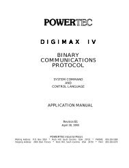
DECEMBER 2005<br />
POWERTEC Industrial Motors<br />
Mailing address: P.O. Box 2650 Rock Hill, South Carolina USA 29732 PHONE: 803-328-1888<br />
Shipping Address: 2606 Eden Terrace Rock Hill, South Carolina USA 29730 FAX: 803-328-1870<br />
Internet: powertecmotors.com