42-Range Digital Multimeter with Electric Field - Radio Shack
42-Range Digital Multimeter with Electric Field - Radio Shack 42-Range Digital Multimeter with Electric Field - Radio Shack
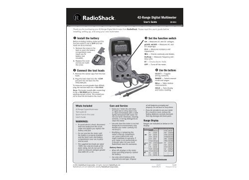
42-Range Digital Multimeter User’s Guide 22-811 Thank you for purchasing your 42-Range Digital Multimeter from RadioShack. Please read this user’s guide before installing, setting up, and using your new multimeter. � Install the battery Before installing battery, make sure the function switch is set to OFF and test leads are disconnected. 1. Remove the screw on the back to open the battery compartment cover. Install one 9V battery (not included). 2. Replace the cover and secure it with the screw. � Connect the test leads 1. Remove the rubber caps from the test leads. 2. Plug the black lead into the –COM jack and the red lead into the +V.�.mA jack. To measure current greater than 400mA, plug the red test lead into +10A MAX. Note: The buzzer sounds after connecting to the +10A MAX jack to measure anything except current. This reminds you not to touch the test leads to the circuit. Whats Included 42-Range Digital Multimeter Test Leads (2) Spare Fuse (in the case) User’s Guide WARNINGS: • To avoid electric shock, disconnect both test leads from the circuit under test before you replace the battery and fuse. • Do not operate the meter until the battery is properly installed and the back cover and battery compartment cover are in place and secured. • The supplied test leads are rated 1000V. Use only test leads of the same rating, but do not use the meter to measure voltages greater than 600V DC or AC. Care and Service ©2008. RadioShack Corporation. All rights reserved. RadioShack and RadioShack.com are trademarks used by RadioShack Corporation. • Keep your meter dry and clean. If it gets wet or dirty, wipe it dry or clean immediately with a cloth lightly dampened with water. Do not use harsh chemicals, cleaning solvents, or strong detergents to clean the meter. • Use and store the meter in normal temperature environments only. Handle your meter carefully. Do not drop it. • Modifying or tampering the meter’s internal components can cause malfunction and might invalidate its warranty. If your meter is not performing as it should, take it to your local RadioShack store for assistance. Battery Notes: • When displays or the meter stops operating properly, replace the battery. • Use only a fresh battery of the required size and type. Dispose � Set the function switch V — Measures AC and DC voltages. μA/A , mA/A — Measures AC and DC amperage. �/ — Measures resistance and capacitance. / — Checks continuity and diodes. Hz/Duty — Measures frequency and duty cycle. EF ������������������������ OFF — Turns off the meter. � Use the buttons SELECT — Toggles among functions. RANGE — Selects manual mode and ranges. REL — Takes relative measurements. HOLD — Tests display and holds a reading. of old batteries promptly and properly. Do not burn or bury them. • If you do not plan to use your meter for a month or more, remove the battery. Batteries can leak chemicals that may damage electronic parts. Range Display Ranges are indicated as below on the display: Position Range Display Position Range Display 400mV 000.0mV 400� 000.0� 4V 0.000V 4�� 0.000�� V 40V 00.00V 40�� 00.00�� 400V 000.0V 400�� 000.0�� 600V 000V 4�� 0.000�� 400μA 000.0μA 40�� 00.00�� μA/A 4mA 0.000mA �/ 4nF 0.000nF 4A 0.000A 40nF 00.00nF 10A 00.00A 400nF 000.0nF 40mA 00.00mA 4μF 0.000μF mA/A 400mA 000.0mA 40μF 00.00μF 4A 0.000A 10A 00.00A www.radioshack.com 22-811 AO0070ACA1 10A08 Printed in China
- Page 2 and 3: Using Measurement Settings Selectin
- Page 4: Safety Precautions • Do not use t
<strong>42</strong>-<strong>Range</strong> <strong>Digital</strong> <strong>Multimeter</strong><br />
User’s Guide 22-811<br />
Thank you for purchasing your <strong>42</strong>-<strong>Range</strong> <strong>Digital</strong> <strong>Multimeter</strong> from <strong>Radio</strong><strong>Shack</strong>. Please read this user’s guide before<br />
installing, setting up, and using your new multimeter.<br />
� Install the battery<br />
Before installing battery, make sure the<br />
function switch is set to OFF and test<br />
leads are disconnected.<br />
1. Remove the screw on the<br />
back to open the battery<br />
compartment cover.<br />
Install one 9V<br />
battery (not<br />
included).<br />
2. Replace the cover<br />
and secure it <strong>with</strong><br />
the screw.<br />
� Connect the test leads<br />
1. Remove the rubber caps from the test<br />
leads.<br />
2. Plug the black lead into the –COM<br />
jack and the red lead into the<br />
+V.�.mA jack.<br />
To measure current greater than 400mA,<br />
plug the red test lead into +10A MAX.<br />
Note: The buzzer sounds after connecting<br />
to the +10A MAX jack to measure<br />
anything except current. This reminds you<br />
not to touch the test leads to the circuit.<br />
Whats Included<br />
<strong>42</strong>-<strong>Range</strong> <strong>Digital</strong> <strong>Multimeter</strong><br />
Test Leads (2)<br />
Spare Fuse (in the case)<br />
User’s Guide<br />
WARNINGS:<br />
• To avoid electric shock, disconnect<br />
both test leads from the circuit<br />
under test before you replace the<br />
battery and fuse.<br />
• Do not operate the meter until<br />
the battery is properly installed<br />
and the back cover and battery<br />
compartment cover are in place<br />
and secured.<br />
• The supplied test leads are rated<br />
1000V. Use only test leads of the<br />
same rating, but do not use the<br />
meter to measure voltages greater<br />
than 600V DC or AC.<br />
Care and Service<br />
©2008. <strong>Radio</strong><strong>Shack</strong> Corporation. All rights reserved. <strong>Radio</strong><strong>Shack</strong> and<br />
<strong>Radio</strong><strong>Shack</strong>.com are trademarks used by <strong>Radio</strong><strong>Shack</strong> Corporation.<br />
• Keep your meter dry and clean.<br />
If it gets wet or dirty, wipe it dry<br />
or clean immediately <strong>with</strong> a cloth<br />
lightly dampened <strong>with</strong> water. Do<br />
not use harsh chemicals, cleaning<br />
solvents, or strong detergents to<br />
clean the meter.<br />
• Use and store the meter in normal<br />
temperature environments only.<br />
Handle your meter carefully. Do<br />
not drop it.<br />
• Modifying or tampering the<br />
meter’s internal components<br />
can cause malfunction and<br />
might invalidate its warranty. If<br />
your meter is not performing as<br />
it should, take it to your local<br />
<strong>Radio</strong><strong>Shack</strong> store for assistance.<br />
Battery Notes:<br />
• When displays or the meter<br />
stops operating properly, replace<br />
the battery.<br />
• Use only a fresh battery of the<br />
required size and type. Dispose<br />
� Set the function switch<br />
V — Measures AC and DC voltages.<br />
μA/A , mA/A — Measures AC and<br />
DC amperage.<br />
�/ — Measures resistance and<br />
capacitance.<br />
/ — Checks continuity and diodes.<br />
Hz/Duty — Measures frequency and<br />
duty cycle.<br />
EF ������������������������<br />
OFF — Turns off the meter.<br />
� Use the buttons<br />
SELECT — Toggles<br />
among functions.<br />
RANGE — Selects manual<br />
mode and ranges.<br />
REL — Takes relative<br />
measurements.<br />
HOLD — Tests display<br />
and holds a reading.<br />
of old batteries promptly and<br />
properly. Do not burn or bury them.<br />
• If you do not plan to use your meter<br />
for a month or more, remove the<br />
battery. Batteries can leak chemicals<br />
that may damage electronic parts.<br />
<strong>Range</strong> Display<br />
<strong>Range</strong>s are indicated as below on the<br />
display:<br />
Position <strong>Range</strong> Display Position <strong>Range</strong> Display<br />
400mV 000.0mV 400� 000.0�<br />
4V 0.000V 4�� 0.000��<br />
V 40V 00.00V 40�� 00.00��<br />
400V 000.0V 400�� 000.0��<br />
600V 000V 4�� 0.000��<br />
400μA 000.0μA 40�� 00.00��<br />
μA/A 4mA 0.000mA �/ 4nF 0.000nF<br />
4A 0.000A 40nF 00.00nF<br />
10A 00.00A 400nF 000.0nF<br />
40mA 00.00mA 4μF 0.000μF<br />
mA/A 400mA 000.0mA 40μF 00.00μF<br />
4A 0.000A<br />
10A 00.00A<br />
www.radioshack.com<br />
22-811<br />
AO0070ACA1<br />
10A08<br />
Printed in China
Using Measurement<br />
Settings<br />
Selecting <strong>Range</strong>s<br />
1. Set the function switch to a position.<br />
2. Press SELECT to choose a function<br />
(such as continuity ( ) or diode ( )<br />
check function under / ). The<br />
meter is in auto mode. The word<br />
AUTO displays, and the meter<br />
automatically selects a range<br />
according to the rating of the circuit<br />
under test.<br />
You can press RANGE to enter<br />
manual mode. AUTO disappears.<br />
3. In manual mode, press RANGE to<br />
select a range. The measuring unit<br />
and decimal point position together<br />
denote a range.<br />
Refer to the <strong>Range</strong> Display table on<br />
page 1 for range indications on the<br />
display.<br />
To return to auto mode, press and hold<br />
RANGE for 2 seconds.<br />
Using Zero Offset<br />
This applies to the V , μA/A , mA/A ,<br />
�/ , and Hz functions.<br />
The meter shows zero offset for some<br />
ranges, especially the 4nF range of the<br />
capacitance ( ) function. You can use<br />
REL to remove zero offset.<br />
To take measurements <strong>with</strong>out zero<br />
offset:<br />
1. Remove the test leads from any<br />
circuit for the capacitance function,<br />
or touch them together for other<br />
functions.<br />
2. When you see a small value (zero<br />
offset), press REL . The meter is in<br />
manual mode.<br />
3. Take measurements <strong>with</strong> REL<br />
displayed. You get exact measured<br />
values.<br />
Using Relative Measurments<br />
You can take measurements relative<br />
to a reference value. This applies to<br />
the V , μA/A , mA/A , �/ , and Hz<br />
functions. Take resistance measurement<br />
as an example.<br />
1. Set the function switch to �/ to<br />
measure a resistor whose value you<br />
want to use as the reference value.<br />
2. When you see the resistance<br />
reading, press REL .<br />
3. Measure another resistor <strong>with</strong> REL<br />
displayed. You get the tolerance of<br />
this resistor from the reference value.<br />
To exit the relative measurement<br />
function, press REL again.<br />
Testing the Display<br />
Press and hold the HOLD button<br />
when you turn on the meter. The<br />
meter turns on and all segments on<br />
the display appear. Release HOLD to<br />
��������������<br />
Holding a Reading<br />
When you see a reading you want to<br />
keep on the display, press HOLD. The<br />
reading stays until you press a button<br />
or set the function switch to another<br />
position.<br />
Operating the Meter<br />
Always set the function switch to OFF<br />
when you are not using the meter. Your<br />
meter automatically turns off after 30<br />
minutes when left unattended.<br />
To deactivate auto power-off, press<br />
and hold both HOLD and SELECT and<br />
turn on the meter. PLOC displays until you<br />
release HOLD and SELECT. Then the<br />
meter does not turn off automatically.<br />
To activate auto power-off, turn off the<br />
meter and turn on again.<br />
Accurate reading condition:<br />
temperature: 65°F to 83°F (18°C to<br />
28°C); relative humidity:
Measuring Resistance<br />
1. Set the function switch to �/ .<br />
2. Press SELECT to choose<br />
the resistance function<br />
(�, ��, or�� appears after<br />
readings).<br />
3. Power off the circuit under test and<br />
discharge all capacitors.<br />
4. Connect the test leads across<br />
the circuit. Or remove one of the<br />
component’s leads from its circuit<br />
and touch the test leads across the<br />
component.<br />
5. Read the measurement.<br />
Note: The meter has an internal<br />
resistance of small value (zero offset).<br />
To get accurate measurements, you can<br />
simply touch the test leads together to<br />
measure the internal resistance, and<br />
then subtract the internal resistance<br />
from a measurement. Also refer to<br />
“Using Zero Offset” on page 2.<br />
Measuring Capacitance<br />
1. Set the function switch to �/ .<br />
2. Press SELECT to choose<br />
the capacitance function<br />
(nF or μF appears after readings).<br />
3. Power off the circuit under test and<br />
discharge all capacitors.<br />
4. Connect the test leads to the<br />
capacitor, matching the polarities<br />
of the capacitor; or remove one<br />
of the leads of the capacitor from<br />
its circuit and touch the test leads<br />
across the capacitor.<br />
5. Read the measurement.<br />
Notes:<br />
• Electrolytic capacitors have<br />
polarities. Be sure the test leads<br />
match the polarities of such<br />
capacitors.<br />
• The voltages applied across<br />
electrolytic capacitors affect<br />
the measured values. That is, a<br />
measurement taken <strong>with</strong> a low<br />
voltage is lower than that taken<br />
<strong>with</strong> a voltage that approaches the<br />
capacitor’s voltage rating. This meter<br />
cannot use high voltage to set the<br />
electrolyte; it cannot measure the<br />
absolute capacitance value.<br />
• Measurements of low-value<br />
capacitors might match or be close<br />
to the actual input capacitance<br />
of the meter. To measure such<br />
capacitors, use the relative<br />
measurement function (see Using<br />
Relative Measurments on page 2).<br />
• The accuracy of capacitance<br />
measurement depends on the<br />
measurement method and type of a<br />
capacitor. The meter gives reference<br />
measurements only.<br />
Checking Continuity<br />
You can check for open or shorted<br />
electric circuits.<br />
1. Set the function switch to / .<br />
2. Repeatedly press SELECT to choose<br />
the continuity function ( appears).<br />
3. Power off the circuit under test and<br />
discharge all capacitors.<br />
4. Connect the test leads across the<br />
circuit.<br />
• Shrt appears and the buzzer<br />
sounds if the circuit resistance is<br />
less than 50�, meaning the circuit<br />
is continuous or shorted.<br />
• opEn appears if the circuit<br />
resistance is greater than 50�,<br />
meaning the circuit is not<br />
continuous.<br />
Checking Diodes<br />
You can check diodes, transistors, and<br />
other semiconductors for opens, shorts,<br />
and normal operation, and determine<br />
the forward voltage and polarity for<br />
diodes. You can also check LEDs.<br />
1. Set the function switch to / .<br />
2. Press SELECT to choose the diode<br />
function ( appears).<br />
3. Power off the circuit under test and<br />
discharge all capacitors.<br />
4. Connect the test leads across<br />
the device, or remove one of the<br />
component’s leads from its circuit<br />
and touch the test leads across<br />
��������������������������������<br />
reading.<br />
5. Reverse the test leads and observe<br />
the second reading.<br />
• If one reading shows a value and<br />
the other shows O.F, then the<br />
device is good. As the meter shows<br />
a value reading, the anode (+)<br />
side is where the red test lead is<br />
connected.<br />
• If O.F displays for both readings,<br />
then the device is open.<br />
• If both readings show small values<br />
or zero, then the device is shorted.<br />
Notes:<br />
• The values that display during the<br />
diode check show the actual forward<br />
voltage (Max. 2.0V). If the voltage<br />
exceeds 2.0V, then O.F appears,<br />
meaning this meter cannot check<br />
the diode.<br />
• When you check a silicon-type<br />
semiconductor, the values might<br />
vary according to the temperature.<br />
Measuring Frequency/Duty Cycle<br />
You can measure frequencies from 10Hz<br />
to 4MHz and a duty cycle <strong>with</strong> signal<br />
frequencies from 10Hz to 100KHz. The<br />
amplitude of a signal is under the peak<br />
value of 10V.<br />
Page 3<br />
1. Set the function switch to Hz/Duty.<br />
2. Press SELECT to choose the<br />
frequency function (Hz, KHz, orMHz<br />
displays) or the duty cycle function<br />
(% displays).<br />
3. Connect the black test lead to a<br />
ground reference for the signal,<br />
and the red test lead to the signal<br />
source.<br />
4. Read the measurement.<br />
Measuring an <strong>Electric</strong> <strong>Field</strong><br />
You can detect the presence of AC<br />
voltage near AC power cords, wall<br />
switches, or cabling behind a wall. This<br />
lets you easily detect a break in an<br />
electric circuit or locate the source of an<br />
��������������<br />
1. Set the function switch to EF.<br />
2. Remove the test leads from the<br />
meter.<br />
3. Hold the meter and point its top<br />
(where the built-in antenna is) to<br />
the object under test. For best<br />
sensitivity, hold the meter behind<br />
the function switch.<br />
���������������������������������������<br />
1 to 5 bars display (corresponding to<br />
�������������������������������������<br />
sounds.<br />
Replacing the Fuse<br />
If the meter stops working, you might<br />
need to replace the fuse. Use the spare<br />
fuse or a 500mA, 250V, 5 × 20mm fastacting<br />
ceramic fuse.<br />
To replace the fuse:<br />
WARNING: Before replacing the<br />
fuse, make sure both test leads are<br />
disconnected from the circuit under test.<br />
1. Set the function switch to OFF and<br />
disconnect the test leads.<br />
2. Remove the top and bottom screws<br />
on the back to open the case.<br />
3. Remove the blown fuse and wrap<br />
the red ribbon around the new fuse.<br />
Replace the fuse.<br />
4. Replace the back cover and secure it<br />
<strong>with</strong> the screws.<br />
Fuse Installed Spare Fuse
Safety Precautions<br />
• Do not use the meter if you are unfamiliar<br />
<strong>with</strong> electric circuits and testing<br />
procedures.<br />
• This meter is for measuring household AC<br />
voltages. Do NOT try to measure 3-phase,<br />
line-to-line voltages. Use extreme caution<br />
when measuring current and voltage<br />
in commercial electrical panels; always<br />
wear protective leather gloves, a face<br />
����������������������������������������<br />
protection.<br />
�� �������������������������������������������<br />
do not expose the meter to rain or<br />
moisture. It is for indoor use only.<br />
• Use extreme caution when working <strong>with</strong><br />
voltages above 30V. Always power off the<br />
circuit under test before you connect the<br />
test leads to high-voltage points.<br />
• Never apply voltages to the meter that<br />
����������������������������������������������<br />
Never apply more than 600V DC and AC<br />
between the input jacks and ground.<br />
• Never try to probe <strong>with</strong> both test leads at<br />
the same time or hold both test leads in<br />
one hand.<br />
• Always discharge any capacitors of the<br />
circuit under test before you attach the test<br />
leads.<br />
• Because many AC/DC sets have a<br />
potentially hot chassis, be sure the top of<br />
���������������������������������������<br />
it are made of non-conductive materials.<br />
• Use the meter as instructed here, or the<br />
protection it provides may be impaired. To<br />
avoid damage, have the meter repaired by<br />
��������������������������������<br />
Special Panel Markings<br />
500V<br />
MAX<br />
600V<br />
400mA<br />
MAX<br />
CAT II<br />
+10A MAX<br />
UNFUSED<br />
To avoid electric shock and<br />
damage to the meter, do not<br />
connect the common input<br />
terminal (the –COM jack) to any<br />
source that exceeds 500V <strong>with</strong><br />
respect to ground.<br />
The maximum input limit<br />
for voltage measurement<br />
is 600V AC or DC, and the<br />
maximum input limit for current<br />
measurement is 400mA DC or<br />
AC at the +V.�.mA jack.<br />
Caution: RISK OF ELECTRIC<br />
SHOCK! Refer to the complete<br />
operating instructions.<br />
Caution: Be extremely careful<br />
when taking high-voltage<br />
measurements. DO NOT<br />
TOUCH TERMINALS OR TEST<br />
LEAD ENDS.<br />
This equipment is rated for<br />
installation category II (3600 VA<br />
max.).<br />
The maximum input limit for<br />
current measurement using this<br />
jack is 10A DC or AC. This jack is<br />
not fuse-protected.<br />
The meter is protected by<br />
double insulation.<br />
Note: The UL mark does not indicate<br />
that this product has been evaluated by<br />
Underwriters Laboratories for the accuracy<br />
of its readings.<br />
Specifications<br />
Power Supply................ One 9V battery (not included)<br />
Low Battery Indication.................................6.3V ± 0.3V<br />
Maximum Common Mode Voltage...............................<br />
....................................................... 500V DC or RMS AC<br />
Input Impedance.............................. 10M� (DCV/ACV)<br />
Diode Check...............Open circuit voltage: 50 ± 30�<br />
Open circuit voltage:


