LOCAL HEAD LOSS IN PLASTIC PIPELINE JOINT WELDED BY ...
LOCAL HEAD LOSS IN PLASTIC PIPELINE JOINT WELDED BY ...
LOCAL HEAD LOSS IN PLASTIC PIPELINE JOINT WELDED BY ...

You also want an ePaper? Increase the reach of your titles
YUMPU automatically turns print PDFs into web optimized ePapers that Google loves.
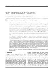
J. Hydrol. Hydromech., 54, 2006, 3, 299–308<br />
<strong>LOCAL</strong> <strong>HEAD</strong> <strong>LOSS</strong> <strong>IN</strong> <strong>PLASTIC</strong> PIPEL<strong>IN</strong>E JO<strong>IN</strong>T <strong>WELDED</strong> <strong>BY</strong> BUTT FUSION<br />
JAN MELICHAR 1) , JAROSLAVA HÁKOVÁ 2) , JAROSLAV VESELSKÝ 3) , LUBOŠ MICHLÍK 4)<br />
1)<br />
Czech Technical University in Prague, Faculty of Mechanical Engineering, Technická 4, 166 07 Prague 6, Czech Republic;<br />
mailto: Jan.Melichar@fs.cvut.cz<br />
2)<br />
Federation for Industrial′s Services CZ, s.r.o., Zelená 34, 160 00 Prague 6, Czech Republic; mailto: slavkah@volny.cz<br />
3)<br />
Czech Technical University in Prague, Faculty of Mechanical Engineering, Technická 4, 166 07 Prague 6, Czech Republic;<br />
mailto: Jaroslav.Veselsky@email.cz<br />
4)<br />
Czech Technical University in Prague, Faculty of Mechanical Engineering, Technická 4, 166 07 Prague 6, Czech Republic;<br />
mailto: Lubos.Michlik@email.cz<br />
Introduction<br />
The article deals with experimental determination of local head loss in straight polypropylene pipeline<br />
(PP) joint connected by butt-welding. A local loss coefficient is introduced for turbulent flow of water in<br />
plastic pipeline of circular cross-section. The value of local loss coefficient has not been experimentally<br />
quantified so far and hence its determination is significant for designers of plastic pipeline systems.<br />
KEY WORDS: Local Loss, Frictional Loss, Plastic Pipelines.<br />
Jan Melichar, Jaroslava Háková, Jaroslav Veselský, Luboš Michlík: MÍSTNÍ ZTRÁTA VE SPOJI<br />
PLASTOVÉHO POTRUBÍ SVAŘOVANÉHO NA TUPO. Vodohosp. Čas., 54, 2006, 3; 5 lit., 7 obr.<br />
Článek pojednává o experimentálním stanovení místní ztráty ve spoji přímého potrubí z polypropylenu<br />
(PP), zhotoveného svařováním na tupo. Je uvedena velikost součinitele místní ztráty spoje plastového<br />
potrubí kruhového průřezu při turbulentním proudění čisté vody. Místní ztráta doposud nebyla<br />
experimentálně kvantifikována, a proto je její stanovení pro projektanty potrubních systémů z plastů<br />
významné.<br />
KLÍČOVÁ SLOVA: místní ztráta, ztráta třením, plastové potrubí.<br />
Pressure pipes for transport of water and other<br />
fluids are used in many branches of industry.<br />
Lately, the use of plastic pipes and fittings is more<br />
frequent in various technological processes. This<br />
results in a new quality for pipe works. It is possible<br />
to substitute a standard steel pipe by plastic<br />
pipe, in particular for a reconstruction of existing<br />
technological equipments. The thermoplastic pipelines<br />
hence become a standard pipeline material.<br />
Polyethylene (PE) and polypropylene (PP) pipelines<br />
are frequently used for pipeline conduits and<br />
water supply networks, as well as for pipelines in<br />
chemical and food processing industry. Using of<br />
linear high-density polyethylene (PE-HD) for building<br />
of long distance pipeline conduits in water supply<br />
and distribution systems, for hydraulic transport<br />
of solid wastes out from thermal power plants, for<br />
transport of coal, ore substratum and gravel has<br />
become common in the well-developed countries.<br />
In the present days PE-HD pipelines of the third<br />
generation enable to be used in severe working<br />
conditions. PE-HD is partially crystalline thermoplastic<br />
and belongs to a member of polyolefin<br />
group. It is rigid and in comparison with PP has<br />
greater hardness and compactness. The polypropylene-homopolymer<br />
β modification pipes (βPP-H) are<br />
used for example for the distribution of high temperature<br />
mediums (lies, acids, thinners) and cold<br />
water.<br />
The knowledge of correct values of friction and<br />
local loss coefficients is important for the designers<br />
of pipeline systems that consist of straight plastic<br />
pipes and constructional elements. Sufficient<br />
amount of experimental data is important for correct<br />
determination of losses. The precise evaluation<br />
of losses enables to obtain the required fluid operation<br />
parameters in the system (flow rate, pressure)<br />
and can markedly affect the optimum operation in<br />
long or complex pipeline conduits.<br />
299
J. Melichar, J. Háková, J. Veselský, L. Michlík<br />
In case of long pipelines like important water<br />
supply pipeline or penstock into hydroelectric<br />
power plants the way of connecting single plastic<br />
tubes is from the mechanical and economical point<br />
of view important. Besides classical and standard<br />
connecting components for tube connections (e.g.<br />
flanged connection, screwed fitting) in particular<br />
glue connecting (eventually chemical welding<br />
while cold) and thermal welding methods are used.<br />
In general, butt-welding is the most common,<br />
most simple and most reliable way of connecting<br />
pipes for long pipeline conduits from PE and PP<br />
materials. During this process of connecting, which<br />
consists of warming-up and melting the ends of<br />
elements prepared for the connection and following<br />
their pressing down, the inner roughness – the emanation<br />
of the material inside pipeline (see Fig. 1) is<br />
created.<br />
Fig. 1. The thermoplastic pipeline joint welded by the buttwelding<br />
method; PE left, PP right.<br />
Obr. 1. Spoj trubek z termoplastů svařovaných metodou na<br />
tupo; PE vlevo, PP vpravo.<br />
The size of a butt weld joint is for certain material<br />
and wall thickness dependent on the welding<br />
process. The exact welding techniques are recommended<br />
for example by instructions of DVS<br />
(Deutscher Verband für Schweisstechnik). The<br />
inner butt weld in the tube represents the specific<br />
kind of inner resistance and results in additional<br />
losses of the fluid flow. The effect of local losses<br />
caused by butt welds on total energy balance for<br />
long pipelines is important. However, in design<br />
practice it is often underestimated or neglected. The<br />
adverse influence of the butt welds on head losses<br />
for fluid flow in a pipeline and a possibility of creation<br />
of cavitation in the jointing point under high<br />
flow velocity is possible to eliminate by using the<br />
300<br />
apparatus for elimination of inner projections, alternatively<br />
by more expensive connecting technology.<br />
However, in design practise it is paradoxically<br />
preferred the use of least expensive connecting<br />
technology over a possibility to eliminate the local<br />
losses and reduce the operating costs.<br />
Insufficient amount of information for the determination<br />
of a local loss coefficient ζ for the butt<br />
weld with a projection is the main problem in design<br />
practice. A certain simplification, for example<br />
approximate analogy between butt weld projections<br />
and an orifice, was considered. However, these<br />
values of the local loss coefficient were only rough<br />
estimates, anticipated parameters of designed systems<br />
were often largely different from real parameters<br />
that were determined after the construction.<br />
Experimental works in the Czech Technical University<br />
Prague, Faculty of Mechanical Engineering<br />
were carried out in order to obtain quantitative values<br />
that provide more accurate assessment of the<br />
local losses for butt welds in jointing point of plastic<br />
pipe from PP and PE materials. The main aim of<br />
this research was to determine the fundamental data<br />
on the local losses that should be usable in design<br />
practice.<br />
The experimental assessment of the local loss<br />
coefficient of the butt weld in jointing point<br />
in PP pipeline<br />
Fig. 2 shows the pipe test that was constructed in<br />
order to determine the local losses for the butt<br />
welds.<br />
The hydrodynamic pump powered by an asynchronous<br />
electric motor provides flow of water<br />
through pipeline. The flow rate through measuring<br />
part of the pipe is possible to change by alternation<br />
of the pump rotation speed through frequency converter<br />
with full open regulation valve situated in the<br />
end of the test loop or by closing and/or opening of<br />
the valve at constant pump speed. The test section<br />
of the test loop (see Fig. 3) was made of straight<br />
polypropylene tube 90 x 8.2 βPP-H S5/SDR11<br />
(equivalent 90 DN80/PN16), which was commercially<br />
available from the manufacturer Georg<br />
Fischer +GF+. These plastic tubes are supplied at<br />
5 m sections. Allowed manufacturing tolerance of<br />
external diameter and wall thickness is prescribed<br />
by the D<strong>IN</strong> 8077 standard and corresponds also<br />
with ISO 4065 standard. The average value of inner<br />
tube diameter in joints d = 72.5 mm was ascertained<br />
by metering.
Local head loss in plastic pipeline joint welded by butt fusion<br />
Fig. 2. Straight pipe for local pressure loss measurement at βPP-H plastics tube joint. Experimental test loop (above): 1 – hydrodynamic<br />
pump, 2 – electromotor with frequency converter, 3 – βPP-H pipeline, 4 – flow regulation valve, 5 – magnetic flow-meter, 6<br />
– butt welded joint, 7 – pressure taps for static pressure, 8 – differential pressure sensors, 9 – A/D conversion unit, 10 – PC.<br />
Obr. 2. Experimentální trasa pro měření místní tlakové ztráty ve spoji plastových trub z βPP-H. Schéma zařízení (nahoře): 1 –<br />
hydrodynamické čerpadlo, 2 – elektromotor s frekvenčním měničem, 3 – βPP-H potrubí, 4 – regulační armatura, 5 – indukční<br />
průtokoměr, 6 – spoj svařením na tupo, 7 – odběry statického tlaku, 8 – diferenční snímače tlaku, 9 – A/D převodník, 10 – PC.<br />
301
J. Melichar, J. Háková, J. Veselský, L. Michlík<br />
Fig. 3. Test section of the test loop, location of pressure taps and pressure-difference sensors; S – pipe jointing point, 1, 2, 3 – pressure<br />
taps.<br />
Obr. 3. Experimentální úsek potrubní trasy, umístění odběrů tlaků a snímačů tlakové diference; S – spoj potrubí, 1, 2, 3 – odběry<br />
statického tlaku.<br />
The horizontal test section of the test loop is<br />
composed of the proper metering pipe length (pipeline<br />
joint between pressure taps 2 and 3) with sufficient<br />
straight pipeline length before (l2S ≈ 5.1d) and<br />
behind the jointing point (lS3 ≈ 10.13d), where the<br />
influence of jointing point on flow pattern is anticipated.<br />
In front of this measuring section there is a<br />
straight pipeline with the corresponding length (l12<br />
= l2S + lS3 = l23 – b = 15.23d). The inner projection<br />
of the butt weld with length b ≈ 0.08d in the pipeline<br />
joint affects the flow in particular behind the<br />
jointing point, where the head loss occurs at relatively<br />
long pipeline length. The losses in a pipeline<br />
before and behind the butt weld or more precisely<br />
the lengths, which we can assume to have significant<br />
influence on flow pattern, depend on the type<br />
of element, its geometric parameters, pipeline wall<br />
roughness and the Reynolds number value. Skalička<br />
(1985) showed that the flow pattern could be sometimes<br />
affected on the distance of 50d behind the<br />
element projection that evokes the head loss. However,<br />
for location of static pressure taps in relation<br />
to measured element there are no any universal<br />
recommendations. With reference to the butt weld<br />
302<br />
geometry and used pipeline material (βPP-H is nontransparent)<br />
the above-mentioned distances between<br />
static pressure taps and examined jointing<br />
point were used. Static pressure taps at a pipeline<br />
cross-section (metering locations) in the experimental<br />
pipeline were made of four pipeline side inlets<br />
that were evenly placed. Fig. 4 shows the detailed<br />
arrangement.<br />
The static pressure differences, ∆p12, between the<br />
cross-section 1 and 2 and ∆p23 between the crosssection<br />
2 and 3 were measured with the use of calibrated<br />
differential pressure sensors with range 0 –<br />
–16 kPa/4 – 20 mA. The estimated accuracy of<br />
pressure difference measurements is up to 0.25 % of<br />
a measuring range. The flow rate, Q, was measured<br />
using magnetic flow meter of type MQI 99<br />
SMART. The accuracy 0.5 % of measured flow rate<br />
was guaranteed within the range of 10 to 100 %<br />
of Qmax. The mercury thermometer was used to<br />
measure the water temperature. The analogue output<br />
signals from the magnetic flow meter and the<br />
differential manometers were compiled by A/D<br />
converter UDAQ – 1208 and transmitted and stored<br />
into PC using program for UDAQ – 1208 proces-
Fig. 4. Annular arrangement of pressure taps.<br />
Obr. 4. Kruhové odběry statického tlaku.<br />
sing unit. The volumetric flow rate and the pressure<br />
differences average values were shown in a graphical<br />
form and then computed as the arithmetic average<br />
of respective values recorded fifteen times<br />
within interval of 2 seconds. The βPP-H tube jointing<br />
point which is single constructional pipeline<br />
element was made by engine plant according to<br />
DVS 2208/1 in compliance with the requested production<br />
process (direction DVS 2207/1), specifying<br />
the exact warming-up time, the adherence pressure<br />
size and the cooling time for a given material and<br />
wall thickness. Dimensions of this etalon jointing<br />
point are shown in Fig 5. The etalon size is proportional<br />
to the tube inner diameter d = 72.5 mm.<br />
The joint is placed between the straight pipeline<br />
sections, which were possible to be considered as<br />
hydraulically smooth. Absolute roughness of<br />
k ≈ 0.003 mm was found from the manufacturers’<br />
recommendations. Kolář and Vinopal (1963) indicate<br />
that the pipeline is possible to be considered as<br />
hydraulically smooth if it has uniform pipeline wall<br />
roughness and if the following condition 17.85<br />
Re -0.875 ≥ k.d -1 is guaranteed. This condition was<br />
fulfilled for all Reynolds numbers during the experimental<br />
measurements. The flow rate was chosen<br />
with reference to recommended mean velocity<br />
of fluid in order to prevent flow from high flow<br />
velocities that could result in cavitation. For flow<br />
velocities c > 4.3 m s -1 in pipeline with the inner<br />
diameter d = 72.5 mm and with the corresponding<br />
Reynolds numbers Re > 3.4 . 10 5 the cavitation was<br />
indicated at least acoustically. With regard to inner<br />
butt weld geometry the cavitation occurrence<br />
should be considered as another significant restric-<br />
Local head loss in plastic pipeline joint welded by butt fusion<br />
tive factor for velocity selection in the case when<br />
the tube joint method by butt-welding will be selected<br />
and the inner weld projections will not be<br />
removed.<br />
Fig. 5. The inner butt weld geometry of plastic pipe joint 90 x<br />
8.2 βPP-H S5/SDR11 welded by butt method; d 0 ≈ 0.87 d,<br />
b ≈ 0.08 d, b′ ≈ h ≈ 0.04 d.<br />
Obr. 5. Geometrie vnitřního svalku spoje plastových trubek<br />
90 x 8,2 βPP-H S5/SDR11 svařených metodou na tupo;<br />
d0 ≈ 0,87 d, b ≈ 0,08 d, b′ ≈ h ≈ 0,04 d.<br />
303
J. Melichar, J. Háková, J. Veselský, L. Michlík<br />
The head loss generated at the joint of straight<br />
pipeline (local loss) is given by an increase of the<br />
loss at the straight pipeline section with given local<br />
loss against frictional loss at the same system without<br />
local loss. The head losses can be expressed in<br />
terms of fluid specific energy Yz (J kg -1 ), which is<br />
consumed in a given pipeline section. The concrete<br />
values of Yz are determined by computation from<br />
the measured values of pressure difference, ∆p12<br />
and ∆p23.<br />
Along the straight pipeline length between cross<br />
sections 1 and 2 the pressure drop through the frictional<br />
losses can be computed from the Darcy-<br />
Weisbach equation:<br />
304<br />
2<br />
∆ p12 l12 c<br />
Yzf<br />
= = λ.<br />
. . (1)<br />
ρ d 2<br />
The friction factor λ in the case of turbulent flow<br />
in hydraulically smooth straight pipeline depends<br />
only on Reynolds number. For this type of flow it is<br />
possible to use a number of formulas, see for example<br />
at Kolář and Vinopal (1963). Usually, the<br />
Blasius formula is used:<br />
−0.25<br />
λ = 0.3164 . Re<br />
(2)<br />
or formula given by Advani:<br />
−0.237<br />
λ = 0.0032 + 0.221. Re , (3)<br />
where Reynolds number is:<br />
Re =<br />
cd .<br />
. (4)<br />
ν<br />
The validity of formula 2 is usually given in<br />
literature for the range of Reynolds numbers<br />
2 300 < Re
very good agreement between measured values of<br />
the friction factor, λ, and computed ones from Eq.<br />
(3). The results in Fig. 7 show practically constant<br />
value of the local loss coefficient ζ = 0.6 for measured<br />
values of the Reynolds number within a range<br />
of 6.10 4 < Re < 5.10 5 and/or flow velocity 0.77<br />
m s -1 < c < 6.39 m s -1 . According to Kolář and Vinopal,<br />
(1963) value of the local loss coefficient for<br />
a sharp-edged normalised orifice with the same<br />
ratio d0/d = 0.87 is around 1.0, which is by 67 %<br />
greater than the actual measured values of the tube<br />
joints with butt welds. However, according to Idelčik<br />
(1960) this value is only 0.6. It must be pointed<br />
out that the sharp-edged normalised orifice and the<br />
tube joints are quite different pipeline elements and<br />
hence using of more accurate measured value is<br />
justified.<br />
In design practice it may be much easier to work<br />
with equivalent pipe length, le. This is the length of<br />
straight pipeline of the same diameter as the fitting,<br />
which would have the same pressure drop as the<br />
fitting, in our case the pipeline joint with the inner<br />
butt weld. Considering the condition Yz f = Yz l from<br />
Eqs. (1) and (8) the equivalent pipeline length can<br />
be computed as follows:<br />
ζ<br />
le = . d.<br />
(10)<br />
λ<br />
Using Eqs. (10) and (3) for the friction factor λ<br />
and considering pipe diameter and experimentally<br />
0.04<br />
0.03<br />
λ (1) 0.02<br />
Local head loss in plastic pipeline joint welded by butt fusion<br />
determined value ζ = 0.6 the equivalent length of<br />
pipe can be computed. For the above-mentioned<br />
range of flow velocity c through pipeline 90 x 8.2<br />
βPP-H S5/SDR11 the value of the equivalent pipe<br />
length varied from le = 2.23 to 3.33 m. These values<br />
show that the local losses represent important part<br />
of the total losses. This is significant in particular<br />
for long PP pipeline systems. For examples in pipeline<br />
90 x 8,2 βPPH S5/SDR11 with the length of<br />
100 m inner projections of nineteen butt-welded<br />
joints may cause the increase of head losses from<br />
42 to 63 % for the above-mentioned Reynolds<br />
numbers in comparison with the same pipeline<br />
without butt welds.<br />
The geometry of inner projections of the buttwelding<br />
joints in PE tube is rather different. The<br />
ration of d/d0 is approximately the same as for PP<br />
tube joints. The expected projection width b depends<br />
on wall thickness and for the same inner<br />
diameter and wall thickness is for PP tube and PE<br />
tube approximately identical. However, the PE tube<br />
projections have more rounded edge, which leads to<br />
assumption of lower basic local loss coefficient<br />
value in the PE tube joints. It should be pointed out<br />
that correct values of the local loss coefficient ζ<br />
could be determined only experimentally using the<br />
PE tube etalon joints.<br />
Experimental data<br />
Advani Eq. 3<br />
Blasius Eq. 2<br />
5x10<br />
Re (1)<br />
4 5x10⁵ 105 0.01<br />
Fig. 6. Measured and computed values of the friction factors in straight pipeline test section of length l 12 in dependence on the<br />
Reynolds number.<br />
Obr. 6. Porovnání naměřených a vypočtených hodnot součinitelů tření v přímém potrubí délky l 12 v závislosti na Reynoldsově čísle.<br />
305
J. Melichar, J. Háková, J. Veselský, L. Michlík<br />
306<br />
ζ s (1)<br />
0.8<br />
0.6<br />
0.4<br />
0.2<br />
5x10<br />
Re (1)<br />
4 5x10⁵ 105 0.0<br />
Fig. 7. Values of basic local loss coefficient for the βPP-H tube joint ζ in dependence on Reynolds number.<br />
Obr. 7. Hodnoty základního součinitele místní ztráty spoje βPP-H trub ζ v závislosti na Reynoldsově čísle.<br />
Conclusions<br />
The paper shows basic values of the local loss<br />
coefficient for the βPP-H tube joints with butt<br />
welds that were experimentally determined for turbulent<br />
flow with Reynolds numbers within the<br />
range of 60 000 < Re < 500 000. The local loss<br />
basic coefficient at pipeline joints was for the<br />
above-mentioned range of Reynolds numbers constant<br />
with the average value of ζ = 0.6 . This value<br />
was determined for PP tube diameter of 72.5 mm<br />
and for the joint and diameter proportion<br />
d0/d = 0.87 .<br />
It is necessary to point out that in practice the local<br />
loss value can be dependent on various butt<br />
weld dimensions that depend on a technological<br />
process of the assembly. However, taking into account<br />
the exact size variability is practically impossible.<br />
With regard to large pressure drops at buttwelded<br />
PP tube joints that become significant in<br />
particular for long pipelines it is possible to recommend<br />
removing the butt welds projections<br />
and/or using tube joint technology, which would<br />
not result in this kind of local losses.<br />
Acknowledgement. The authors are particularly<br />
grateful to the companies FIS CZ s.r.o. Praha and<br />
BHV sensory s.r.o. Praha. Thanks are expressed to<br />
the Company FIS CZ for necessary material supply<br />
and experimental pipeline assembly and to the<br />
Company BHV for granting the techniques for experimental<br />
measurements.<br />
Received 15. December 2005<br />
Review accepted 14. June 2006<br />
List of symbols<br />
b, b´ – width of inner butt weld projection at pipeline joint<br />
[m], [mm],<br />
c – mean flow velocity [m s -1 ],<br />
d – inner pipeline diameter [m], [mm],<br />
h – height of butt-welds projections [m], [mm],<br />
I – electric current [A], [mA],<br />
K – constant in Eq.(6),<br />
k – hydraulic roughness of inner pipeline wall [mm], constant<br />
in Eq.(9),<br />
l – length of straight pipelines sections [m], [mm],<br />
p – static pressure [Pa],<br />
Q – flow rate [m 3 s -1 ],<br />
Re – Reynolds number [–],<br />
T – fluid temperature [ 0 C],<br />
Y – specific fluid energy [J kg -1 ],<br />
λ – friction factor [–],<br />
ν – kinematic viscosity [m 2 s -1 ],<br />
ρ – fluid density [kg m -3 ],<br />
ζ – local loss coefficient [–],<br />
∆ – difference.<br />
Subscripts<br />
e – equivalent,<br />
f – frictional,<br />
l – local loss,<br />
s – pipeline joints,<br />
z – loss-making,<br />
0 – at pipe contraction,<br />
12, 2S, S3 – at cross sections between marked locations,<br />
eventually between pressure taps.<br />
REFERENCES<br />
HÁK V., 2002: Long force main projection speciality by pipeline<br />
thermoplastic PE-HD application. (In Czech.) Heating,<br />
ventilation, installation no. 4, p, 142–145.<br />
IDELČIK I. E., 1960: Handbook of hydraulic. (In Russian.)<br />
Moskva: Gosenergoizdat, p. 123.
KOLÁŘ V., V<strong>IN</strong>OPAL S., 1963: Hydraulics of industrial<br />
armature. (In Czech.) I. publication, Prague, SNTL, p. 64–<br />
181.<br />
MELICHAR J., BLÁHA J., HÁKOVÁ J., 2004: Contribution<br />
to possibility of using plastics pipeline for fluid transport at<br />
waterpower engineering. (In Czech.) Hydroturbo 2004 – International<br />
conference of Water power engineering. Brno<br />
2004, p. 243–252.<br />
SKALIČKA J., 1985: Local hydraulic loss by stable pressure<br />
flow. (In Czech.) Pumps, pipeline, armature no. 2-3, p. 10–<br />
–15.<br />
MÍSTNÍ ZTRÁTA VE SPOJI PLASTOVÉHO<br />
POTRUBÍ SVAŘOVANÉHO NA TUPO<br />
Jan Melichar, Jaroslava Háková,<br />
Jaroslav Veselský, Luboš Michlík<br />
Tlaková potrubí pro dopravu vody i jiných kapalin se<br />
používají v mnoha odvětvích národního hospodářství.<br />
V poslední době se v řadě technologických procesů stále<br />
více uplatňují potrubí a armatury z plastů, které představují<br />
novou kvalitu částí zařízení čerpací techniky. Standardní<br />
ocelové potrubí může být v opodstatněných<br />
případech nahrazeno potrubím z plastů, zejména při rekonstrukci<br />
stávajících technologických zařízení. Termoplasty<br />
se tak stávají standardním potrubním materiálem.<br />
Často používanými plasty pro stavbu potrubních rozvodů<br />
a sítí ve vodárenství, chemickém a potravinářském<br />
průmyslu jsou polyetylény (PE) a polypropylény (PP).<br />
Používání lineárních vysokohustotních polyetylenů (PE-<br />
HD) při stavbě dlouhých potrubních řadů ve<br />
vodárenských potrubních soustavách, v hydrodopravě<br />
tuhých odpadů energetických centrál, uhelných<br />
a rudných substrátů a štěrkopísků, je dnes již ve<br />
vyspělých zemích běžné. V současnosti zaváděné<br />
lineární PE-HD 3. generace umožňují aplikace do nejtěžších<br />
provozních podmínek. Potrubí z polypropylenuhomopolymeru<br />
β modifikace (βPP-H) se používají např.<br />
pro rozvody médií s vysokou teplotou (louhy, kyseliny,<br />
ředidla) a studené vody.<br />
Pro projektanty potrubních systémů, složených<br />
z přímých plastových trub a nezbytných konstrukčních<br />
prvků, je důležitá znalost konkrétních hodnot součinitelů<br />
třecích a místních ztrát. Pro spolehlivý návrh systému,<br />
resp. pro co možná nejpřesnější výpočet velikosti hydraulických<br />
ztrát, je důležitý dostatek experimentálně<br />
ověřených podkladů. Správné určení velikosti hydraulických<br />
ztrát rozhoduje o splnění požadovaných parametrů<br />
kapaliny v systému (průtok, tlak) a výrazně<br />
může ovlivnit hospodárnost provozu systému, zejména<br />
u dlouhých nebo členitých potrubních řadů.<br />
U dlouhých potrubních řadů, jako jsou např. vodovodní<br />
potrubí nebo přivaděče vodních elektráren, je<br />
z technicko-ekonomického hlediska významný způsob<br />
spojování jednotlivých plastových trub. Při spojování<br />
částí plastového potrubí se vedle klasických spojovacích<br />
prvků (např. přírubové spoje, šroubení) uplatní hlavně<br />
spojování lepením (popř. chemickým svařováním za<br />
Local head loss in plastic pipeline joint welded by butt fusion<br />
studena) a tepelným svařováním. Svařování na tupo je<br />
v běžné praxi nejobvyklejším, nejjednodušším<br />
a spolehlivým způsobem spojování trub v dlouhých<br />
potrubních řadech z PE a PP. Při této technologii spojování,<br />
sestávající z ohřevu a natavení konců spojovaných<br />
dílů a jejich následného přítlaku, však v místě<br />
spoje vznikají vnitřní nerovnosti – svalky v potrubí.<br />
Vnitřní svalek v potrubí představuje specifický typ<br />
místního odporu, způsobujícího ztráty mechanické energie<br />
proudu při průtoku kapaliny. Vliv svalky způsobených<br />
lokálních ztrát na celkovou energetickou bilanci<br />
dlouhých potrubních řadů není zanedbatelný,<br />
v projektové praxi však bývá často podceňován nebo<br />
opomíjen. Nepříznivý vliv vnitřních svalků na velikost<br />
ztrát při proudění kapaliny potrubím a možnost vzniku<br />
kavitace v místě spoje při vysokých rychlostech<br />
proudění lze eliminovat použitím zařízení k odstranění<br />
vnitřního svalku, případně využitím nákladnější technologie<br />
spojování. V praxi však někdy bývá paradoxně<br />
upřednostňována nejméně nákladná technologie spojování<br />
před možností snížení nákladů provozních, a to<br />
vyloučením místních ztrát energie ve spojích trub.<br />
Problémem v projekční činnosti je nedostatek dostupných<br />
podkladů pro stanovení základní hodnoty součinitele<br />
místní ztráty spoje ζ . Při stanovení výpočtových<br />
hodnot součinitelů ζ spoje s vnitřním svalkem se dosud<br />
vycházelo ze zjednodušení, jakým je například určitá<br />
analogie mezi svalkem a potrubní clonou. Je ale zřejmé,<br />
že svalek a normalizovaná potrubní clona jsou tvarově<br />
odlišné prvky. Odhadované hodnoty součinitele místní<br />
ztráty byly orientační, předpokládané parametry<br />
navržených systémů se mnohdy lišily od parametrů skutečných,<br />
zjištěných až po realizaci zařízení. K získání<br />
kvantitativních hodnot, umožňujících přesnější stanovení<br />
velikosti místních ztrát na vnitřním svalku ve spoji<br />
plastových trub z PE a PP, byly proto provedeny na<br />
Fakultě strojní ČVUT v Praze experimentální práce.<br />
Cílem bylo získání základních údajů o velikosti výše<br />
uvedené místní ztráty, které by byly využitelné<br />
v projekční praxi.<br />
Seznam použitých symbolů<br />
b, b′ – šířka vnitřního svalku ve spoji potrubí [m], [mm],<br />
c – rychlost proudění kapaliny [m s -1 ],<br />
d – vnitřní průměr potrubí [m], [mm],<br />
h – výška svalku [m], [mm],<br />
I – proud [A], [mA],<br />
K – konstanta ve vztahu (6) [kg m -6,25 s -0,25 ],<br />
k – hydraulická drsnost vnitřní stěny potrubí [mm], konstanta<br />
ve vztahu (9) [m 7 kg -1 ],<br />
l – délka rovných úseků potrubí [m], [mm],<br />
p – statický tlak [Pa],<br />
Q – průtok [m 3 s -1 ],<br />
Re – Reynoldsovo číslo [–],<br />
T – teplota kapaliny [°C],<br />
Y – měrná energie kapaliny [J kg -1 ],<br />
λ – součinitel tření [–],<br />
ν – kinematická viskozita [m 2 s -1 ],<br />
307
J. Melichar, J. Háková, J. Veselský, L. Michlík<br />
ρ – měrná hmotnost kapaliny [kg m -3 ],<br />
ζ – součinitel místní ztráty [–],<br />
∆ – rozdíl.<br />
Indexy<br />
e – ekvivalentní,<br />
f – třecí,<br />
308<br />
l – místní ztráty,<br />
s – spoje potrubí,<br />
z – ztrátová,<br />
0 – v místě zúžení průtočného průřezu,<br />
12, 2S, S3 – v úseku mezi vyznačenými místy, příp. mezi<br />
odběry tlaku.