Connection sockets have changed! - Generex GmbH
Connection sockets have changed! - Generex GmbH
Connection sockets have changed! - Generex GmbH

Create successful ePaper yourself
Turn your PDF publications into a flip-book with our unique Google optimized e-Paper software.
User Manual – English<br />
Copyright of the European Union is effecti ve (Copyright EU) (c) 2011 GENEREX <strong>GmbH</strong>, Hamburg, Germany, All rights reserved<br />
TEL +49( 40)22692910 - EMAIL info@generex.de - WEB www.generex.de (This and all other product datasheets ar e available for downl oad.)<br />
Version: 2010-12-15<br />
SITEMONITOR II
Copyright Statement for Intellectual Property and Confidential Information<br />
The information contained in this manual is non-conditional and may be <strong>changed</strong> without due<br />
notice. Although <strong>Generex</strong> has attempted to provide accurate information within this<br />
document, <strong>Generex</strong> assumes no responsibility for the accuracy of this information.<br />
<strong>Generex</strong> shall not be liable for any indirect, special, consequential, or accidental damage<br />
including, without limitations, lost profits or revenues, costs of replacement goods, loss or<br />
damage to data arising out of the use of this document<br />
<strong>Generex</strong> the manufacturer of the BACS products undertakes no obligations with this<br />
information. The products that are described in this brochure are given on the sole basis of<br />
information to its channel partners for them to <strong>have</strong> a better understanding of the <strong>Generex</strong><br />
products.<br />
<strong>Generex</strong> allows its channel partners to transfer information contained in this document to<br />
third persons, either staff within their own Company or their own customers, either<br />
electronically or mechanically, or by photocopies or similar means. <strong>Generex</strong> states that the<br />
content must not be altered or adapted in any way without written permission from <strong>Generex</strong>.<br />
It is agreed that all rights, title and interest in the <strong>Generex</strong>’s trademarks or trade names<br />
(whether or not registered) or goodwill from time to time of <strong>Generex</strong> or in any intellectual<br />
property right including without limitation any copyright, patents relating to the Products, shall<br />
remain the exclusive property of <strong>Generex</strong>.<br />
<strong>Generex</strong> will undertake to deal promptly with any complaints about the content of this<br />
document. Comments or complaints about the document should be addressed to <strong>Generex</strong><br />
Systems <strong>GmbH</strong>.<br />
Copyright of the European Union is effective (Copyright EU).<br />
Copyright (c) 1995-2012 GENEREX <strong>GmbH</strong>, Hamburg, Germany. All rights reserved.<br />
2<br />
Copyright of the European Union is effecti ve (Copyright EU) (c) 2011 GENEREX <strong>GmbH</strong>, Hamburg, Germany, All rights reserved<br />
TEL +49( 40)22692910 - EMAIL info@generex.de - WEB www.generex.de (This and all other product datasheets ar e available for downl oad.)
English Manual<br />
Dieses Handbuch ist auch in Deutsch verfügbar!<br />
Eine aktuelle Kopie erhalten Sie unter download bei www.generex.de.<br />
This manual is also available in German!<br />
To obtain an actual copy please see the download-page of www.generex.de<br />
Copyright of the European Union is effecti ve (Copyright EU) (c) 2009 GENEREX <strong>GmbH</strong>, Hamburg, Germany, All rights reserved<br />
TEL +49( 40)22692910 - EMAIL info@generex.de - WEB www.generex.de (This and all other product datasheets ar e available for downl oad.)<br />
3
Contents<br />
English Manual 3<br />
1. About the SITEMONITOR II 5<br />
1.1 General information 5<br />
1.2 Features 5<br />
2. Installation 6<br />
2.1 Connectors and connections 6<br />
2.1.1 Digital input connectors 6<br />
2.2 Status LED’s 8<br />
3. Getting started – Ba sic settings 9<br />
4. Configuration of the input connectors 11<br />
4.1 Connected devices 11<br />
4.2 Alarm matrix 12<br />
4.3 Status display 13<br />
4.3.1 Input status 13<br />
5. Event Handling, UPS functionalities 14<br />
5.1.1 Events … 15<br />
5.1.2 Email Job 16<br />
5.1.3 Notification via SMS 16<br />
5.1.4 RCCMD - Perform shutdown signals to net work computers 17<br />
Appendix 19<br />
A. SITEMONITOR II – technical data 19<br />
Table of figures 19<br />
4<br />
Copyright of the European Union is effecti ve (Copyright EU) (c) 2011 GENEREX <strong>GmbH</strong>, Hamburg, Germany, All rights reserved<br />
TEL +49( 40)22692910 - EMAIL info@generex.de - WEB www.generex.de (This and all other product datasheets ar e available for downl oad.)
1. About the SITEMONITOR II<br />
1.1 General information<br />
The SITEMONITOR is a monitoring unit for professional use. The 19“ rack unit can be used for<br />
monitoring both electronic equipment and rooms and is equally well suited for industrial monitoring<br />
purposes. The SITEMONITOR has 64 digital inputs for various electrical contact detectors like smoke<br />
alarms, motion detectors, door intrusion detectors and alarm switches. Additional features allow for the<br />
programming of alarms that are composed of several inputs. The states of each alarm input are<br />
indicated by their own illuminating diodes on the front panel of the device. The electrical connections<br />
are located on the backside of the device in the form of terminal strips.<br />
The complete configuration of the SITEMONITOR can be done within the easy to use web browser<br />
interface for setting things like network parameters and alarm functions. In addition to the LAN<br />
connection, the SITEMONITOR also has an RS-232 interface for connecting another serial device like<br />
a UPS (uninterruptible power supply). The SITEMONITOR provides RS -232 protocol support for<br />
several thousand different UPS devices. This makes the SITEMONITOR the only device of its kind on<br />
the market that can support and evaluate practically all UPS protocols with the inclusion of all of their<br />
status and measurement values. All of the measured values can be visualized using either a web<br />
browser, the Windows client included with delivery or the optional UNMS Network Management<br />
Software. SNMP protocol standard functions are also supported. Other interesting functions are also<br />
available via the LAN connection. The SITEMONITOR is capable of transmitting network messages to<br />
most operating systems.<br />
1.2 Features<br />
Figure 1: SITEMONITOR’s front side<br />
64 digital inputs (opened (NO) / closed (NC) configurable)<br />
10/ 100Mbit LAN<br />
Supported protocols: email, HTTP, SNMP, SNTP, RFC868, Modbus Over IP, UPSMON, UNMS<br />
RS-232 interface for other devices, i.e. connects to almost all UPS models<br />
Remote configuration via web browser or UNMS Software (Optional)<br />
LED alarm display, LED operating status display<br />
Battery backed real-time clock with timeserver synchronization via internet or with UPS internal clock<br />
Flash memory for alarm texts<br />
19"-chasis, only 1 HE<br />
Copyright of the European Union is effecti ve (Copyright EU) (c) 2009 GENEREX <strong>GmbH</strong>, Hamburg, Germany, All rights reserved<br />
TEL +49( 40)22692910 - EMAIL info@generex.de - WEB www.generex.de (This and all other product datasheets ar e available for downl oad.)<br />
5
6<br />
Configuration via Web interface<br />
UPS interface<br />
2. Installation<br />
Figure 2: SITEMONITOR with UPS<br />
The figure above shows a typical installation of the SITEMONITOR with a UPS connected. Imagine,<br />
that a numerous kind of input devices can be connected to the SITEMONITOR.<br />
2.1 Connectors and connections<br />
The backside of the SITEMONITOR II incorporates the following connectors as shown below:<br />
Figure 3: SITEMONITOR’s backside<br />
Power supply: Connect the included external power supply unit (DC, 12V).<br />
DIP switch 1,2: With the DIP switches it is possible to change between configuration mode and<br />
normal operating mode. How to use the DIP switches please follow the instructions in section 3<br />
Getting started – Basic settings.<br />
COM 1 port: If necessary, connect the UPS with the original vendors UPS cable.<br />
LAN connector: Connect the SITEMONITOR with an RJ45 cable to the network.<br />
LINE: Port for external RAS service.<br />
64 digital input <strong>sockets</strong>.<br />
2.1.1 Digital input connectors<br />
The 64 digital input <strong>sockets</strong> are suited in one bank.<br />
Copyright of the European Union is effecti ve (Copyright EU) (c) 2011 GENEREX <strong>GmbH</strong>, Hamburg, Germany, All rights reserved<br />
TEL +49( 40)22692910 - EMAIL info@generex.de - WEB www.generex.de (This and all other product datasheets ar e available for downl oad.)
Figure 4: Input <strong>sockets</strong><br />
Please follow the circuit examples as shown below for the pin assignment of the digital input <strong>sockets</strong>.<br />
Figure 5: Pin assignment of the digital input <strong>sockets</strong><br />
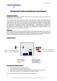
ATTENTION! <strong>Connection</strong> <strong>sockets</strong> <strong>have</strong> <strong>changed</strong>!<br />
Before activating the device notice the following !<br />
The Digital Input <strong>sockets</strong> of the SiteMonitorII from SN:SMG04-00023 or higher <strong>have</strong> <strong>changed</strong>. The<br />
lower <strong>sockets</strong> X1 deliver the power supply of 15 VDC and the Digital Input <strong>sockets</strong> D01 -D64 are on<br />
the upper ports of X2. (Fig.:Digital Inputs SiteMonitorII).<br />
Please notice the Fig. Schematic Digital Inputs when you connect your devices<br />
Klemmenbezeichnung: Anschluss:<br />
X1 / 15V + Betriebsspannung<br />
+15VDC<br />
X1 / - GND -<br />
X2/D01 Digital Input 1<br />
X2/D02 Digital Input 2<br />
X2/D03 Digital Input 3<br />
X2/D04 Digital Input 4<br />
X2/D05 Digital Input 5<br />
X2/D06 Digital Input 6<br />
X2/D07 Digital Input 7<br />
X2/D08 Digital Input 8<br />
X2/D09 Digital Input 9<br />
X2/D10 Digital Input 10<br />
X2/D11 Digital Input 11<br />
X2/D12 Digital Input 12<br />
X2/D13 Digital Input 13<br />
X2/D14 Digital Input 14<br />
Copyright of the European Union is effecti ve (Copyright EU) (c) 2009 GENEREX <strong>GmbH</strong>, Hamburg, Germany, All rights reserved<br />
TEL +49( 40)22692910 - EMAIL info@generex.de - WEB www.generex.de (This and all other product datasheets ar e available for downl oad.)<br />
7
8<br />
Fig.: Schematic Digital Inputs<br />
Fig.: Digital Inputs SiteMonitorII<br />
2.2 Status LED’s<br />
The status of each Input connector is shown by the LED at the SITEMONITOR’s front display whereas<br />
a green lit LED indicates, that the output/input is active and a red LED is shown in the case of a alarm<br />
(the LED is flashing while the alarm is not acknowledged).<br />
Figure 6: Status LED’s at Webinterface<br />
The actual status is also shown at the SITEM ONITOR’s web interface (see figure above) to monitor<br />
the devices on remote. Here, 4 status are differentiated:<br />
X2/D15 Digital Input 15<br />
X2/D16 Digital Input 16<br />
X2/D17� D64 Digital Input 17� 64<br />
Copyright of the European Union is effecti ve (Copyright EU) (c) 2011 GENEREX <strong>GmbH</strong>, Hamburg, Germany, All rights reserved<br />
TEL +49( 40)22692910 - EMAIL info@generex.de - WEB www.generex.de (This and all other product datasheets ar e available for downl oad.)
LED Status<br />
Gray / unlit Input / Output is not active<br />
Green Input / Output is active<br />
Red Alarm<br />
Yellow Alarm acknowledged and still active<br />
3. Getting started – Ba sic settings<br />
First of all the startup of the SITEMONITOR requires some basic settings by which the unit will be<br />
integrated into the network environment:<br />
Set DIP switch 1 and 2 to position OF F after having connected the LAN port with an RJ45 cable to<br />
the network and - where required – having connected the UPS at COM1 (with the original vendors<br />
cable). This sets the SITEMONITOR to the configuration mode and enables the default IP address<br />
10.10.10.10. Plug in the power supply then to initiate the boot process. A running boot procedure is<br />
indicated with green flashing of the power LED at the S ITEMONITOR’s front display.<br />
When the SITEMONITOR has finished its boot procedure (indicated with permanent green<br />
lightening of the power LED) a network connection can be built up. To establish a connection the<br />
network must route the SITEMONITOR’s answers under 10.10.10.10 to your local host. Usually you<br />
<strong>have</strong> to set a temporary route for this: Open the command promt and type “route print” to see the<br />
actual routes. Use the command “route add 10.10.10.10 ” to extend the actual<br />
routing table. Ping the adapter on IP-address 10.10.10.10 and you should receive the answers.<br />
Figure 7: Route command and routing table<br />
Connect your Webbrowser (MS-Internet Explorer and Mozilla are supported) to the address<br />
http://10.10.10.10 to reach the SITEMONITOR’s Webinterface. First of all the HTTP interface requires<br />
a logon whereas you use the username “admin” and the default password “cs121-snmp”.<br />
Copyright of the European Union is effecti ve (Copyright EU) (c) 2009 GENEREX <strong>GmbH</strong>, Hamburg, Germany, All rights reserved<br />
TEL +49( 40)22692910 - EMAIL info@generex.de - WEB www.generex.de (This and all other product datasheets ar e available for downl oad.)<br />
9
Figure 8: HTTP - logon<br />
10<br />
Call the menue “Network & Security”. Make the settings for “Local Address”, “Gateway Address”<br />
and “Subnet Mask” (where required also for “DNS -Server”). Apply your settings with the button on the<br />
right buttom side of the menu.<br />
Figure 9: HTTP- Basic network settings<br />
If a UPS is connected at the SITEMONITOR’s serial COM1 port it is necessary to set some UPS<br />
parameters. Therefor call the menu “UPS-Model & System” and select from the drop-down menu the<br />
connected UPS model. Apply your settings with the button on the right bottom side of the menu.<br />
Call the menu “Save Configuration” and choose the option of the same name.<br />
Set DIP-Switch 1 to position ON, whereas DIP-Switch 2 stays in position OFF. Remove and insert<br />
the power supply from the Sitemanager to initiate the reboot process. See the power LED’s to verify<br />
the reboot process.<br />
Reconnect the Webbrowser with the device using the configured IP address. (http://”). If you don’t get an answer, please observe, that the routing table contains a route for<br />
the SITEMONITOR’s IP address.<br />
The basic settings are now completed and the SITEMONITOR is integrated into the network<br />
environment.<br />
Copyright of the European Union is effecti ve (Copyright EU) (c) 2011 GENEREX <strong>GmbH</strong>, Hamburg, Germany, All rights reserved<br />
TEL +49( 40)22692910 - EMAIL info@generex.de - WEB www.generex.de (This and all other product datasheets ar e available for downl oad.)
4. Configuration of the input connectors<br />
4.1 Connected device s<br />
Figure 10: HTTP – COM2 settings to SiteMonitor 2<br />
Generally, the SITEMONITOR’s COM2 port is set to mode “SiteMonitor 2”. This enables the<br />
congfiguration page “Sitemonitor II” in the configuration menu.<br />
Figure 11: HTTP menu with SITEMONITOR II configuration<br />
Use this menu to configure the devices at the input <strong>sockets</strong>. The 64 digital inputs can be configured<br />
within the following section.<br />
Figure 12: Configuration – Digital Inputs<br />
Copyright of the European Union is effecti ve (Copyright EU) (c) 2009 GENEREX <strong>GmbH</strong>, Hamburg, Germany, All rights reserved<br />
TEL +49( 40)22692910 - EMAIL info@generex.de - WEB www.generex.de (This and all other product datasheets ar e available for downl oad.)<br />
11
Name the connected devices and set whether the contact is closed or not in its normal operating<br />
mode (Field NC Contact). Enable “Active” for all connected devices. (Only active devices will be<br />
evaluated)<br />
Enable the parameter “Hold”, if an occurred Alarm ought to be kept until the alarm is acknowledged<br />
and not ought to be reset, when the contact moves in normal position. A digital input marked with<br />
“Hold” causes, that for example a motion detector, which gives the alarm contact only for a short<br />
period of time, will be indicated and treated as alarm even if the contact has moved in its normal<br />
position again. If the Alarm occurred once it is active and has to be acknowledged to set it back to<br />
normal mode.<br />
12<br />
Note: If you do not want to use a name for the Digital Inputs, please set the following into the<br />
single name area: <br />
4.2 Alarm matrix<br />
The following “Alarm Matrix” gives you numerous possibilities to configure dependencies beetween<br />
different alarm states. This makes it possible to process an alarm szenario in dependency of the state<br />
of serveral input sensors. (For example: An alarm szenario is to be released only if two contacts<br />
indicate an alarm or if the air condition is not active.)<br />
Figure 13: Alarm matrix – Marker 1-8 configuration<br />
In the figure above the alarm matrix is shown with its 8 markers to be set or unset. Each marker<br />
thereby is a new state on which specific alarm szenarios can be released.<br />
For example: In the figure above is configurated that the Marker1 will be set, when at one of the input<br />
2, 5, 9, 10 or 15 an alarm occurs. (Enabling the field “Marker Inverted” causes that Marker1 will be<br />
unset in case of an alarm at one of the inputs) Furthermore marker 2 will be set, when at the input 2,<br />
5, 7, 11, 13 and 14 an alarm state accurs at the same time. (Means that an alarm at just one input is<br />
not sufficent for setting marker 2) Accordingly it is possible to set (or unset) each marker in<br />
dependency of different input states.<br />
Copyright of the European Union is effecti ve (Copyright EU) (c) 2011 GENEREX <strong>GmbH</strong>, Hamburg, Germany, All rights reserved<br />
TEL +49( 40)22692910 - EMAIL info@generex.de - WEB www.generex.de (This and all other product datasheets ar e available for downl oad.)
After having defined the conditions when markers are to be set resp. unset, you can specify the<br />
actions to be executed when an marker will be set/unset. Therefor you can handle each marker<br />
through the event configuration, described later on in section 5 Event . This is possible because each<br />
marker has its own event “Alarm Marker x”, which can be configured through the event configuration.<br />
Furthermore the matrix configuration gives you the possibility to combine and set conditions between<br />
the Markers. Therefor you <strong>have</strong> an additional matrix, figured on below. In the example is configurated<br />
that Output 3 is to be switched, when Marker 1 or Marker 2 is set (or the opposite way around in case<br />
“Output Inverted” is enabled).<br />
Figure 14: Alarm matrix – Output 1 - 8 configuration<br />
4.3 Status display<br />
The SITEMONITOR II incorporates different pages for monitoring. Choose in the menu “Network &<br />
Security” which status page is the HTTP default page and will be displayed on startup of every HTTP<br />
connection.<br />
4.3.1 Input status<br />
Monitore the state of the connected devices through the menu “Sitemonitor II Status” (default setting<br />
for HTTP default page).<br />
Figure 15: Menu for status display<br />
The status display gives you an overview of the actual input status. Additionally, you <strong>have</strong> the<br />
possibility to acknowledge alarms (Button “Ack”) as shown in the figure below.<br />
Copyright of the European Union is effecti ve (Copyright EU) (c) 2009 GENEREX <strong>GmbH</strong>, Hamburg, Germany, All rights reserved<br />
TEL +49( 40)22692910 - EMAIL info@generex.de - WEB www.generex.de (This and all other product datasheets ar e available for downl oad.)<br />
13
Figure 16: Status display overview<br />
5. Event Handling, UPS functionalities<br />
The Event/Alarm configuration is based on a combination of events and actions (resp. Jobs). At the<br />
Sitemonitor there are various events defined, e.g. events concerning the attached devices like “Alarm<br />
Input 1”, “Alarm Digital Input 1” etc. and also events concerning a connected UPS like “Powerfail”,<br />
“UPS Battery bad”, “Battery low” etc.<br />
The Sitemonitor allows you to release one or more actions on each event. An action can be e.g. to<br />
write a logfile entry in the alarm logfile (as default all events do perform an logfile event), to send an<br />
eMail or to perform an RCCMD-Command (e.g. shutdown signals to several RCCMD Clients).<br />
14<br />
To configure events and actions open the menu “Events / Alarms”. The menu “Event<br />
Configuration” shows you an overview about the events and the number of configured actions.<br />
Figure 17: HTTP - Event Configuration with tool tip<br />
Choose the event you wish to configure with the event editor.<br />
Figure 18: HTTP - Event Editor<br />
The Event Editor allows you to edit, delete and test existing events, as well as to add a new event job.<br />
Just click on the desired action to enter the Job Editor, who lets you make the c onfiguration.<br />
Copyright of the European Union is effecti ve (Copyright EU) (c) 2011 GENEREX <strong>GmbH</strong>, Hamburg, Germany, All rights reserved<br />
TEL +49( 40)22692910 - EMAIL info@generex.de - WEB www.generex.de (This and all other product datasheets ar e available for downl oad.)
5.1.1 Events …<br />
Please call the menu “Events / Alarms” at the Webbrowser to open the main configuration site,<br />
whereon all configurable events are listed.<br />
In the Sitemonitor’s menu “Event overview” you see on top a couple of events concerning the state of<br />
an connected UPS (usually numbered from 1). Which events are actual available depends on<br />
connected UPS model. In the following, we introduce the main and important events which should be<br />
handled in general, if a UPS is connected to the Sitemonitor.<br />
Powerfail<br />
The event “Powerfail” will be released when the UPS has lost the power supply. This event is usually<br />
used to proceed operations like backup-strategies, batch-files to be executed on client stations etc. pp.<br />
You can configure such jobs with the “Remaining time”-parameter to ensure the actions will be<br />
executed completely.<br />
System shutdown<br />
The event “system shutdown” will be released, if the configurated “System Shutdown Time” (in the<br />
menu “UPS model and system”) is reached. This means, there are yet the configurated minutes left<br />
until the battery’s capacity is expected to be finished (as calculated by the SITEMONITORs adapter).<br />
This event should only be used to proceed all operations concerning your forced shutdown szenarios.<br />
Further operations are usually configurated on the event “Powerfail”.<br />
Note: This EVENT is the final task the SITEMONITOR can initiate before the UPS<br />
switches off! DO NOT use this event for triggering shutdowns via RCCMD etc.<br />
because the remaining time in this status is not secure. We strongly recommend to<br />
use the event “Powerfail” and configure the RCCMD shutdown calls with a UPS<br />
“remaining time”, this is the best way to send RCCMD shutdowns to several IP -<br />
addresses in a certain logic or sequence!<br />
Battery low<br />
The event “Battery low” will be released from the UPS when the battery charge has reached a critical<br />
state.<br />
UPSMAN started<br />
The event “UPSMAN started” is periodically released in normal operating mode. You can use this<br />
event to configure jobs, which should be executed as long as the SITEMONITOR is working in normal<br />
mode.<br />
Note: Same UPS models allows you to configure the thresholds for releasing UPS specific<br />
events individual. The SITEMONITOR also supports these features if the UPS<br />
includes this possibility.<br />
Continuous, periodic events:<br />
To define an event job which will be executed continuous, e.g. daily, create a job on the event<br />
„UPSMAN started“, as in the following figure:<br />
Copyright of the European Union is effecti ve (Copyright EU) (c) 2009 GENEREX <strong>GmbH</strong>, Hamburg, Germany, All rights reserved<br />
TEL +49( 40)22692910 - EMAIL info@generex.de - WEB www.generex.de (This and all other product datasheets ar e available for downl oad.)<br />
15
Figure 19: HTTP - Job Editor: Continuous event job<br />
For example the configuration as shown above causes, that each day (is equivalent to 86400<br />
seconds) an email to “someone@somewhere.com” will be sent, until the Sitemonitor is in normal<br />
operating mode.<br />
Furthermore each connected device at the input <strong>sockets</strong> has its own event which allows to release<br />
specific actions in dependency of the status of the device. Therefor the following events are<br />
supported:<br />
16<br />
Alarm Input 1-64: Will be released, if the contact state indicates an alarm. (Opposite of NC contact)<br />
5.1.2 Email Job<br />
Figure 20: HTTP - Job Editor: Email-Job<br />
To configure an Email job follow the entries in the figure above.<br />
Note: It is condition before you configure an Email job that you <strong>have</strong> made the Email<br />
settings in the menu “Email”. Please observe, that the entries are valid, before<br />
testing.<br />
Apply your settings and test the Email-job in the “Event Editor” to ensure Email will be sent.<br />
5.1.3 Notification via SMS<br />
From firmware version 4.17.x or higher is a new function available, which offers a notification via SMS.<br />
Just use a simple 1:1 cable for the connection of the SiteManager II/v3 and the GSM modem.<br />
Figure 21: HTTP - Job Editor: Send SMS with GSM modem<br />
Copyright of the European Union is effecti ve (Copyright EU) (c) 2011 GENEREX <strong>GmbH</strong>, Hamburg, Germany, All rights reserved<br />
TEL +49( 40)22692910 - EMAIL info@generex.de - WEB www.generex.de (This and all other product datasheets ar e available for downl oad.)
Set the telephone number of the receiver and the text into the accordant areas .<br />
LED Status Display<br />
Operating Status: LED Signaling:<br />
SIM card not present Slowly red flashing<br />
SIM card active Fast red flashing<br />
Figure 22: Siemens GSM TMA T35i modem<br />
Into the menu “System & Network Status” you can see the signal level of the modem, to adjust your<br />
antenna optimal. Green means a good signal is present.<br />
Figure 23: HTTP – „System & Network Status“<br />
5.1.4 RCCMD - Perform shutdown signals to network computers<br />
RCCMD (Remote Console Command) is the world’s most successful shutdown client for<br />
heterogeneous networks and is the most secure way to establish a UPS multiple server shutdown<br />
sequence today. RCCMD clients are listening to an RCCMD server which is usually an UPSMAN<br />
software, CS121 or any third-party UPS manager which has a license to use RCCMD. An RCCMD<br />
server is found inside any CS121 and is triggering RCCMD clients in case of alarms. Therefore<br />
RCCMD requires such listeners on each client-computer you wish to forward RCCMD signals. For<br />
installation of RCCMD at client-side please see the section in chapter “Add-on software”.<br />
Note: RCCMD clients are optional and not freeware. Most SITEMONITORs are equipped<br />
License regulations:<br />
today with a single RCCMD standard license, some UPS makers add more licenses,<br />
other do not deliver any license at all with a CS121. Contact your UPS maker and<br />
ask for the license regulations for RCCMD in conjunction with your SITEMONITOR.<br />
Please note that in order to use these functions legally, the corresponding RCCMD client program is<br />
installed and started from the UPS-Management Software CD. The RCCMD license code can only be<br />
Copyright of the European Union is effecti ve (Copyright EU) (c) 2009 GENEREX <strong>GmbH</strong>, Hamburg, Germany, All rights reserved<br />
TEL +49( 40)22692910 - EMAIL info@generex.de - WEB www.generex.de (This and all other product datasheets ar e available for downl oad.)<br />
17
used once per installation. If more computers need to be added to the shutdown process, additional<br />
RCCMD client licenses are required.<br />
To send shutdown-signals to computers in case of a powerfail event you <strong>have</strong> to install and configure<br />
the RCCMD client at the computers you want to shutdown and make some configurations at the<br />
adapter’s event settings.<br />
18<br />
Note: All network components, such as routers, hubs etc. need to be full UPS-supported,<br />
as it is otherwise not possible to reach all clients during the network shutdown.<br />
Installation of the RCCMD client: You find a setup procedure for RCCMD on the UPS<br />
Management Software CD or downloadable from www.generex.de.<br />
The RCCMD Setup contains a wizard, which guides you through the installation. At the first window<br />
you <strong>have</strong> to enter the IP address of the SITEMONITOR, from which the client receives the RCCMD<br />
shutdown-signal. Confirm the following pre-settings and mind the shutdown file at the ultimate window.<br />
Press „Configure“ to edit the actual shutdown sequence at the client. (Alternatively you can also edit<br />
the batchfile to add or change the actions to be executed.) Finally press „Install“ to complete the<br />
configuration and to start the RCCMD service.<br />
Note: Each RCCMD installation needs its own licence code. Usually the SITEMONITOR<br />
package contains at least one licence (depends on the model). C ontact your UPS<br />
dealer to obtain further licence codes.<br />
Configuration of the SITEMONITOR’s’s event se ttings: Call the menu “Events & Alarms” at the<br />
adapter’s HTTP-configuration, click on the event “Powerfail” and press the button “Add new job” to<br />
open the Job Editor.<br />
There, choose as function from the drop-down menu the option “Send RCCMD Shutdown to remote<br />
client” and enter the IP-address of the client. (the listener port is usually 6003) At the right side you<br />
can specifiy when the shutdown-signal is to be released, e.g. „do after 300 seconds“.<br />
Note: For security reasons we recommend to make the same RCCMD shutdown entries at<br />
„Powerfail“ for the Event “Battery low” - but here without any delays to avoid that the<br />
server crashes because of low battery alarm!<br />
Copyright of the European Union is effecti ve (Copyright EU) (c) 2011 GENEREX <strong>GmbH</strong>, Hamburg, Germany, All rights reserved<br />
TEL +49( 40)22692910 - EMAIL info@generex.de - WEB www.generex.de (This and all other product datasheets ar e available for downl oad.)
Appendix<br />
A. SITEMONITOR II – technical data<br />
Eingangsspannung: 230V AC +/- 5%<br />
Maximale Stromaufnahme: 0,3 A<br />
Ruhestrom: typ. 25mA (bei 230V Eingangsspannung<br />
Maße: 430 mm x 156 mm x 44 mm (BxTxH)<br />
mit Halterwinkeln: 19”, 1 HE<br />
Betriebstemperatur: 0 - 40°C<br />
Rel. Luftfeuchte: 0 - 95%, nicht betauend<br />
Schutzart: IP 20<br />
Table of figures<br />
Figure 1: SITEMONITOR’s front side 5<br />
Figure 2: SITEMONITOR with UPS 6<br />
Figure 3: SITEMONITOR’s backside 6<br />
Figure 4: Input <strong>sockets</strong> 7<br />
Figure 5: Pin assignment of the digital input <strong>sockets</strong> 7<br />
Figure 6: Status LED’s at Webinterface 8<br />
Figure 7: Route command and routing table 9<br />
Figure 8: HTTP - logon 10<br />
Figure 9: HTTP- Basic network settings 10<br />
Figure 10: HTTP – COM2 settings to SiteMonitor 2 11<br />
Figure 11: HTTP menu with SITEMONITOR II configuration 11<br />
Figure 12: Configuration – Digital Inputs 11<br />
Figure 13: Alarm matrix – Marker 1-8 configuration 12<br />
Figure 14: Alarm matrix – Output 1 - 8 configuration 13<br />
Figure 15: Menu for status display 13<br />
Figure 16: Status display overview 14<br />
Figure 17: HTTP - Event Configuration with tool tip 14<br />
Figure 18: HTTP - Event Editor 14<br />
Figure 19: HTTP - Job Editor: Continuous event job 16<br />
Figure 20: HTTP - Job Editor: Email-Job 16<br />
Figure 21: HTTP - Job Editor: Send SMS with GSM modem 16<br />
Figure 22: Siemens GSM TMA T35i modem 17<br />
Figure 23: HTTP – „System & Network Status“ 17<br />
Copyright of the European Union is effecti ve (Copyright EU) (c) 2009 GENEREX <strong>GmbH</strong>, Hamburg, Germany, All rights reserved<br />
TEL +49( 40)22692910 - EMAIL info@generex.de - WEB www.generex.de (This and all other product datasheets ar e available for downl oad.)<br />
19