Quickstart â BACS Installation Safety instructions - Generex GmbH
Quickstart â BACS Installation Safety instructions - Generex GmbH
Quickstart â BACS Installation Safety instructions - Generex GmbH

Create successful ePaper yourself
Turn your PDF publications into a flip-book with our unique Google optimized e-Paper software.
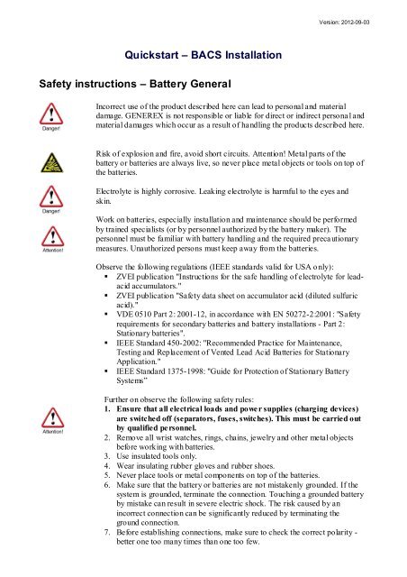
<strong>Quickstart</strong> – <strong>BACS</strong> <strong>Installation</strong><br />
<strong>Safety</strong> <strong>instructions</strong> – Battery General<br />
Version: 2012-09-03<br />
Incorrect use of the product described here can lead to personal and material<br />
damage. GENEREX is not responsible or liable for direct or indirect personal and<br />
material damages which occur as a result of handling the products described here.<br />
Risk of explosion and fire, avoid short circuits. Attention! Metal parts of the<br />
battery or batteries are always live, so never place metal objects or tools on top of<br />
the batteries.<br />
Electrolyte is highly corrosive. Leaking electrolyte is harmful to the eyes and<br />
skin.<br />
Work on batteries, especially installation and maintenance should be performed<br />
by trained specialists (or by personnel authorized by the battery maker). The<br />
personnel must be familiar with battery handling and the required precautionary<br />
measures. Unauthorized persons must keep away from the batteries.<br />
Observe the following regulations (IEEE standards valid for USA only):<br />
� ZVEI publication "Instructions for the safe handling of electrolyte for leadacid<br />
accumulators."<br />
� ZVEI publication "<strong>Safety</strong> data sheet on accumulator acid (diluted sulfuric<br />
acid)."<br />
� VDE 0510 Part 2: 2001-12, in accordance with EN 50272-2:2001: "<strong>Safety</strong><br />
requirements for secondary batteries and battery installations - Part 2:<br />
Stationary batteries".<br />
� IEEE Standard 450-2002: "Recommended Practice for Maintenance,<br />
Testing and Replacement of Vented Lead Acid Batteries for Stationary<br />
Application."<br />
� IEEE Standard 1375-1998: "Guide for Protection of Stationary Battery<br />
Systems”<br />
Further on observe the following safety rules:<br />
1. Ensure that all electrical loads and power supplies (charging devices)<br />
are switched off (separators, fuses, switches). This must be carried out<br />
by qualified personnel.<br />
2. Remove all wrist watches, rings, chains, jewelry and other metal objects<br />
before working with batteries.<br />
3. Use insulated tools only.<br />
4. Wear insulating rubber gloves and rubber shoes.<br />
5. Never place tools or metal components on top of the batteries.<br />
6. Make sure that the battery or batteries are not mistakenly grounded. If the<br />
system is grounded, terminate the connection. Touching a grounded battery<br />
by mistake can result in severe electric shock. The risk caused by an<br />
incorrect connection can be significantly reduced by terminating the<br />
ground connection.<br />
7. Before establishing connections, make sure to check the correct polarity -<br />
better one too many times than one too few.
8. Filled lead-acid batteries contain highly explosive gas (hydrogen/ air<br />
mixture). Never smoke, handle open flames or create sparks near the<br />
batteries. Always avoid electrostatic discharge; wear cotton clothing and<br />
ground yourself if necessary.<br />
9. Wear the appropriate safety clothing and equipment.<br />
For further information refer to the battery makers <strong>instructions</strong> for installation, commissioning and<br />
operating of their battery products.<br />
<strong>Safety</strong> <strong>instructions</strong> – <strong>BACS</strong> safety precautions<br />
Attention<br />
High voltage<br />
warning<br />
Magnetic<br />
emissions<br />
<strong>Installation</strong> by<br />
qualified<br />
personnel only!<br />
Warning!<br />
Check Modules<br />
during<br />
installation and<br />
initial charging<br />
Do not open the <strong>BACS</strong> sensor modules. Do not attach any<br />
kind of objects to the battery or the <strong>BACS</strong> modules itself<br />
apart from the connecting cables! The <strong>BACS</strong> modules and<br />
cables could be live!<br />
Do not apply any magnetic sensitive equipment near the<br />
<strong>BACS</strong> Webmanager, like monitors, disk drives, memory<br />
chips or magnetic tapes.<br />
The <strong>BACS</strong> installation should only be installed by<br />
qualified personnel. <strong>BACS</strong> is to be installed on batteries<br />
where high voltages could cause injuries or even death if<br />
not handled properly!<br />
The <strong>BACS</strong> connection cables (temperature cable, bus<br />
cable, measuring cable) could be live! To avoid short<br />
circuits, do not touch, replace or cut the <strong>BACS</strong> cables,<br />
before having disconnected the system off the batteries!<br />
<strong>BACS</strong> modules must NOT be mounted on a damaged<br />
battery! If a battery is damaged and the internal resistance<br />
is extremely high, the charge current, respectively<br />
discharge current would not flow through the battery but<br />
rather would search for a way with the lowest resistance,<br />
through the <strong>BACS</strong> module. In this case heating could<br />
destroy the <strong>BACS</strong> module. Therefore never use batteries,<br />
which are obviously damaged or show extremely high<br />
internal resistances.<br />
The GENEREX service technician should watch the<br />
<strong>BACS</strong> modules and the initial charge during the<br />
installation. It should be checked, if the <strong>BACS</strong> modules get<br />
very hot. This would be an indication for a damaged<br />
battery or incorrect mounted cables. Do not leave the<br />
installation place, before the <strong>BACS</strong> system has been<br />
completely installed and the battery charge has started for<br />
60 minutes. The system is safe and can be monitored<br />
remote, if the <strong>BACS</strong> system shows normal internal<br />
Copyright of the European Union is effecti ve (Copyright EU) (c) 2012 GENEREX Systems <strong>GmbH</strong>, H amburg, Ger many, All rights reserved<br />
TEL +49( 40)22692910 - EMAIL gener ex@generex.de - WEB www.generex.de (This and all other product datasheets ar e available for downl oad.)
Exact observation<br />
of the battery<br />
temperature up to<br />
12 hours after<br />
discharging<br />
resistance values and the voltages are stable.<br />
Observe battery temperature for up to 12 hours after a<br />
discharge period! The risk of thermal runaways (for VRLA<br />
batteries) is elevated direct after discharges when the<br />
charging process is started. Rising temperatures in<br />
damaged battery cells / blocs can cause fire. The highest<br />
risk of a thermal runaway and subsequent system damages<br />
has to be expected during approx. 12 hours after battery<br />
discharge. React immediately if the battery cell / bloc<br />
temperature rises after discharge phase instead of a slow<br />
decrease or stagnation.<br />
<strong>Safety</strong> <strong>instructions</strong> – for <strong>BACS</strong> configuration and installation<br />
Avoid installations in certain areas<br />
Do not install <strong>BACS</strong> in the following areas:<br />
In rooms which are not protected from water or high humidity, in wet or dusty places<br />
In areas with constantly high concentration of salted or oxidising gases<br />
Near to open flames, flying sparcs or heat sources, as well as in areas with extreme heat or at<br />
places with high variations in temperature.<br />
In areas with high vibrations or mechanical movements.<br />
In areas with high gas concentration or flammable materials.<br />
Monitoring System - Configure and monitor alarms<br />
<strong>BACS</strong> is a monitoring system and should be handled accordingly, assure a correct setting of the<br />
alarm threshold and appropriate reaction in case of alarms!<br />
<strong>BACS</strong> is a tool to increase the durability of the accumulators but its most important function is<br />
monitoring of the battery to avoid breakdowns. It is required to ensure a reaction within a couple<br />
of hours after any alarm. <strong>BACS</strong> is not able to balance battery or charger failures constantly but<br />
provides through its EQUALISATION and alerting functions, an advance warning time which<br />
should be used in any case to avoid fatal damages!<br />
Never mix different <strong>BACS</strong> C Module versions or <strong>BACS</strong> Measuring cabletypes ! You must not use<br />
<strong>BACS</strong> C REV 2 or 3 on the same Batterysystem, nor use <strong>BACS</strong> BC2 or BC5 cables on the same<br />
batterysystem or use BC2 cables with C Modules REV 3. This would damage the modules or lead<br />
to wrong measurings.<br />
For questions and comments refer to:<br />
www.generex.de<br />
support@generex.de<br />
Copyright of the European Union is effecti ve (Copyright EU) (c) 2012 GENEREX Systems <strong>GmbH</strong>, H amburg, Ger many, All rights reserved<br />
TEL +49( 40)22692910 - EMAIL gener ex@generex.de - WEB www.generex.de (This and all other product datasheets ar e available for downl oad.)
1. <strong>Quickstart</strong> - <strong>Installation</strong> of the <strong>BACS</strong> Hardware<br />
The installation of <strong>BACS</strong> consists of 4 major steps. The steps 1 to 3 are described in<br />
this “<strong>Quickstart</strong>” as follows. Please refer to the <strong>BACS</strong> user manual und <strong>BACS</strong><br />
Viewer Software manual for further informations.<br />
1.1 <strong>Installation</strong> of <strong>BACS</strong> Cables, Module, Converter & Splittbox<br />
1.1.1 Connect the <strong>BACS</strong> Measuring Cable BC4 or BC5<br />
Assemble the supply- and measuring cables type BCxxx nearby the battery terminals or rather the battery<br />
connectors. Please note the right polarity, red cable at the plus terminal (+), black cable at the minus terminal<br />
(-). Please tighten the terminal and monitoring screws with the torque as denoted by the battery<br />
manufacturer.<br />
Figure 1: Typical assembling of a <strong>BACS</strong> Measuring Cable (here BC5)<br />
Attention : Please note, that the usage of wrong cables may damage the internal fuses of the cable, the<br />
<strong>BACS</strong> module or rather the safety function of the <strong>BACS</strong> is not functional. Make sure to use only the following<br />
combinations :<br />
<strong>BACS</strong> C20 REV1+2 = <strong>BACS</strong> measuring cable type BC2. (Identification: Without any label on the cable)<br />
<strong>BACS</strong> C30 REV1 = <strong>BACS</strong> measuring cable type BC3, (Identification: yellow coil label around the fuse)<br />
<strong>BACS</strong> C40, C42REV3 = <strong>BACS</strong> measuring cable type BC4 (Identification: Text BC4 printed on the black wire)<br />
<strong>BACS</strong> C20,C23,C30 REV3 = <strong>BACS</strong> measuring cable type BC5, (Identification: Text BC5 printed on the black<br />
wire, see the following figure)<br />
Figure 2: BC5 Cable identification – text inscription at the black negative Measuring Cable<br />
Advice : The usage of stainless steel washers or connector material distort s the RI measuring at<br />
accumulators with a very low resistance. Please note this, if you want to compare the <strong>BACS</strong> RI measurings<br />
with a reference measuring device.<br />
Please note, that the eyelet of the measuring cable should not be smaller than the washer to avoid wrong RI<br />
measurings. The surface of the measuring cable shoe should be ideally the same as the surface of the<br />
battery pole.<br />
Please check the following pictures to ensure an optimal cable installation.<br />
Copyright of the European Union is effecti ve (Copyright EU) (c) 2012 GENEREX Systems <strong>GmbH</strong>, H amburg, Ger many, All rights reserved<br />
TEL +49( 40)22692910 - EMAIL gener ex@generex.de - WEB www.generex.de (This and all other product datasheets ar e available for downl oad.)
Connection of a BC5 measuring cable at a 6V or 12V battery<br />
Connection of BC4 measuring cable at a 2V cell with 2 poles<br />
Connection of a BC4 measuring cable at a 2V cell with 4 or more poles<br />
1.1.2 Connection of the <strong>BACS</strong> Measuring Cables to the <strong>BACS</strong> C Modules<br />
After installing the <strong>BACS</strong> measuring cables, connect the 4 Pole connector with the <strong>BACS</strong> modules. Insert the<br />
connector until you can feel that the lock is closed. Detach the foil of the Velcro underneath of the <strong>BACS</strong><br />
module and the Temperature sensor and fix the <strong>BACS</strong> module on the top of the battery or on the side as<br />
near to the top of the battery as possible. At REV 3 2 foils have to be removed. The smaller one is for the<br />
integrated temperature sensor into the housing, which should be in contact with the surface of the<br />
accumulator.<br />
Copyright of the European Union is effecti ve (Copyright EU) (c) 2012 GENEREX Systems <strong>GmbH</strong>, H amburg, Ger many, All rights reserved<br />
TEL +49( 40)22692910 - EMAIL gener ex@generex.de - WEB www.generex.de (This and all other product datasheets ar e available for downl oad.)
Optional REV 3 : You can order an external temperature sensor for the REV 3. This one will be mounted as<br />
the REV 2 as follows.<br />
REV 2 : This type of C Module hat its temperature sensor on a 10cm cable which has to be placed on the<br />
battery surface. Detach the foil at the temperature sensor and place the sensor nearby the housing of the<br />
accumulator (not on cooling fins nor closing plugs). Please note, that the surface is clean to assure an<br />
accurate attachment of the sensor.<br />
Note: Never mix different <strong>BACS</strong> C modules ! Eg. REV 2 must not be used with REV 3 on the same battery<br />
system.<br />
The supply and measuring<br />
cable connected to a <strong>BACS</strong> C<br />
module<br />
<strong>BACS</strong> C module fixed with velcro<br />
strip on a accumulator<br />
Figure 3: Assembling and Connection of the Module<br />
All modules should be connected together via the <strong>BACS</strong> RJ10 bus-cables (Part No. B2BCRJ10xxx) using<br />
the 2 sockets at the back of the <strong>BACS</strong> module. Connect with these bus-cables all the modules in series (any<br />
socket of the <strong>BACS</strong> module can be used, it does not matter if left or right socket). The last cable has to be<br />
connected to the <strong>BACS</strong> BUS CONVERTER or to the <strong>BACS</strong> WEBMANAGER Input. It is not required to built<br />
up a ring, so the last <strong>BACS</strong> module may be connected only with one cable.<br />
Copyright of the European Union is effecti ve (Copyright EU) (c) 2012 GENEREX Systems <strong>GmbH</strong>, H amburg, Ger many, All rights reserved<br />
TEL +49( 40)22692910 - EMAIL gener ex@generex.de - WEB www.generex.de (This and all other product datasheets ar e available for downl oad.)
<strong>BACS</strong> Bus cable<br />
Figure 4: <strong>BACS</strong> bus cables (Part No. B2BCRJ10xx) connected to a <strong>BACS</strong> CONVERTER<br />
<strong>BACS</strong> Bus cable<br />
Figure 5: <strong>BACS</strong> bus cables connected to a <strong>BACS</strong> WEBMANAGER BUDGET II internal CONVERTER<br />
<strong>BACS</strong> Bus cable<br />
Figure 6: <strong>BACS</strong> bus cables connected to a <strong>BACS</strong> WEBMANAGER BUDGET Slot version - For usage with<br />
UPS, Inverters, Rectifiers, Chargers or other devices with such a compatible slot type<br />
Copyright of the European Union is effecti ve (Copyright EU) (c) 2012 GENEREX Systems <strong>GmbH</strong>, H amburg, Ger many, All rights reserved<br />
TEL +49( 40)22692910 - EMAIL gener ex@generex.de - WEB www.generex.de (This and all other product datasheets ar e available for downl oad.)
OPTION : For battery systems with more than 40<br />
batteries, we recommend the usage of a <strong>BACS</strong><br />
Splitting Box (Part. No. BCII_SPLITT). A<br />
SPLITTINGBOX is for avoiding extreme bus cable<br />
length and allows the installation engineer to<br />
optimize the bus cable route for tidy installation.<br />
Figure 7: <strong>BACS</strong> SPLITTING BOX<br />
<strong>BACS</strong> Bus cable<br />
Figure 8: <strong>BACS</strong> bus cables connected to a SPLITTBOX - CONVERTER – <strong>BACS</strong> WEBMANAGER<br />
The <strong>BACS</strong> bus connection cables are specially designed products (using twisted cables and special<br />
covering) the cables are available in different length. We strongly recommend using these cables to avoid<br />
false alarms through EMI or other noise.<br />
Advice: You can connect the modules to the bus in random order. It is not required to connect the modules<br />
serially in order of the module connection to the bus. We recommend arranging the bus wiring in a way to<br />
avoid unnecessary length.<br />
1.1.3 Connect <strong>BACS</strong> Bus cables to Converter & Webmanager<br />
The <strong>BACS</strong> BUS CONVERTERs provide a galvanic isolation of the battery bus from the <strong>BACS</strong><br />
WEBMANAGER; additionally it filters possible EMI and converts the <strong>BACS</strong> bus protocol to an RS232<br />
protocol. The active EMI filter in the <strong>BACS</strong> BUS CONVERTER requires a power supply 12 – 18 VDC.<br />
The <strong>BACS</strong> Battery bus cables are connected to the first <strong>BACS</strong> module in your system or to the <strong>BACS</strong><br />
SPLITTINGBOX. The other side has to be connected with the <strong>BACS</strong> WEBMANAGER, using the included 1<br />
m cable.<br />
Attention ! Do not connect any <strong>BACS</strong> bus cable type B2BCRJxxx into the COM3/AUX port of the<br />
<strong>BACS</strong> WEBMANAGER ! This port is designed for the usage with the 6-pin original cable, which is containing<br />
into the scope of delivery of every <strong>BACS</strong> WEBMANAGER. If any other cable will be connected here, it could<br />
damage the contacts and might cause addressing and communication problems with your <strong>BACS</strong> BUS<br />
CONVERTER and <strong>BACS</strong> Modules ! The <strong>BACS</strong> WEBMANAGER BUDGET 1 COM3/AUX port is therefore<br />
sealed with a lable to avoid damages. Remove this lable after having read this information and connect only<br />
the correct <strong>BACS</strong> BUS CONVERTER Cable here, not any <strong>BACS</strong> B2BCRJxxx cable.<br />
Copyright of the European Union is effecti ve (Copyright EU) (c) 2012 GENEREX Systems <strong>GmbH</strong>, H amburg, Ger many, All rights reserved<br />
TEL +49( 40)22692910 - EMAIL gener ex@generex.de - WEB www.generex.de (This and all other product datasheets ar e available for downl oad.)
Figure 9: <strong>BACS</strong> WEBMANAGER BUDGET II, COM3/AUX Port Warning Label<br />
Figure 10: <strong>BACS</strong> WEBMANAGER BUDGET II typical setup<br />
There are several different types of <strong>BACS</strong> BUS CONVERTERS. Depending on your model, please c onnect<br />
the <strong>BACS</strong> Bus cable from the first module or <strong>BACS</strong> Splitting box to the <strong>BACS</strong> BUS CONVERTOR and install<br />
the Power supply cable to the box. The Bus cables connects the convertor to the <strong>BACS</strong> WEBMANAGER<br />
BUDGET. If you are installing the <strong>BACS</strong> WEBMANAGER BU DGET 2 the BUS CONVERTER is now<br />
incorporated into the <strong>BACS</strong> WEBMANAGER and no extra power supply is required. The <strong>BACS</strong> cable from<br />
the first module or <strong>BACS</strong> splitting box is connected direct to the <strong>BACS</strong> WEBMANAGER.<br />
Figure 11: <strong>BACS</strong> Webmanager Budget II with integrated CONVERTER<br />
Figure 12: <strong>BACS</strong> Bus Converter III for use with <strong>BACS</strong> WEBMANAGER BUDGET slot cards and External<br />
Copyright of the European Union is effecti ve (Copyright EU) (c) 2012 GENEREX Systems <strong>GmbH</strong>, H amburg, Ger many, All rights reserved<br />
TEL +49( 40)22692910 - EMAIL gener ex@generex.de - WEB www.generex.de (This and all other product datasheets ar e available for downl oad.)
1.1.4 FINISH Step 1: Finish the <strong>Installation</strong> of the <strong>BACS</strong> Hardware<br />
The installation of the <strong>BACS</strong> sensor, consisting of <strong>BACS</strong> measuring cables, <strong>BACS</strong> C modules, <strong>BACS</strong> bus<br />
cables, <strong>BACS</strong> SPLITTING BOX and <strong>BACS</strong> CONVERTER is now finished.<br />
At this point the <strong>BACS</strong> modules are not yet functional. The modules are not addressed yet generally. You<br />
can do this via the <strong>BACS</strong> PROGRAMMER Software (for Windows) or via the <strong>BACS</strong> WEBMANAGER directly.<br />
Now we have to configure the <strong>BACS</strong> WEBMANGER to set up the addressing of the Modules.<br />
The installation of the hardware is now finished. Please take a look into chapter 2 for the<br />
configuration of the <strong>BACS</strong> WEBMANAGER.<br />
2. Configuration of the <strong>BACS</strong> WEBMANAGER<br />
<strong>BACS</strong>® WEBMANAGER BUDGET<br />
Figure 13: <strong>BACS</strong> WEBMANAGER BUDGET external, this is also available as SLOT card for UPS<br />
Description Function<br />
1 COM1 connector Connection w ith an UPS or another end-device via a RS232-cable.<br />
2 COM2 connector Connection for optional devices like a modem, multi sensor SENSORMANAGER, temperature sensor, humidity,<br />
field busses (MODBUS, RS232, Profibus, LONBus, etc.).<br />
3 LAN-Socket Ethernet 10/100 Mbit interface with integrated LEDs (green LED: connection to the network established, yellow<br />
LED: netw ork-activity).<br />
4 DC-Input Pow er supply 9-30VDC/250mA through external power supply, DC-connector inside (-) minus, outside (+) plus.<br />
5 COM 3 <strong>BACS</strong><br />
Bus<br />
6 LEDs (red and<br />
green)<br />
For the connection to the <strong>BACS</strong> ® CONVERTER, use only the original cable coming w ith the <strong>BACS</strong> Busconverter !<br />
Optical displays (red = Boot process/error, green = ok).<br />
7 DIP Sw itch For the switch between configuration mode (both switches off) and normal mode (sw itch 1 on, switch 2 off).<br />
8 Alarm LED Alarm LED of the integrated CONVERTER (BUDGET II only).<br />
Copyright of the European Union is effecti ve (Copyright EU) (c) 2012 GENEREX Systems <strong>GmbH</strong>, H amburg, Ger many, All rights reserved<br />
TEL +49( 40)22692910 - EMAIL gener ex@generex.de - WEB www.generex.de (This and all other product datasheets ar e available for downl oad.)
9 MUTE Button Button for the acknow ledgement and mute of the horn. Alarm LED changes to yellow .<br />
10 <strong>BACS</strong> Bus For the connection to the <strong>BACS</strong> C modules.<br />
<strong>BACS</strong> ® WEBMANAGER BUDGET LED Status<br />
Operating Conditions of <strong>BACS</strong> Webmanager LEDs LED-Signaling<br />
Start procedure 1, up loading of the OS red flashing<br />
Start procedure 2, reboot of the OS red long on<br />
If the red and green LED shine at your <strong>BACS</strong> Webmanager during the reboot, large broadcast traffic is present on<br />
your network „receive buffer overflow“. The green LED is signalizing at the reboot, that the „traffic buffer“ is full.<br />
Advice: You should filter broadcasts via your sw itch, because it comes to performance losing of the <strong>BACS</strong><br />
Webmanager unnecessary.<br />
Copyright of the European Union is effecti ve (Copyright EU) (c) 2012 GENEREX Systems <strong>GmbH</strong>, H amburg, Ger many, All rights reserved<br />
TEL +49( 40)22692910 - EMAIL gener ex@generex.de - WEB www.generex.de (This and all other product datasheets ar e available for downl oad.)<br />
red AND green<br />
during reboot<br />
Normal condition green flashing<br />
UPS communication lost red constantly<br />
2.1 Setup and Network Configuration of the <strong>BACS</strong> WEBMANAGER<br />
Note: We recommend the following settings for the operation of the CS121 via cross cable<br />
(Ethernet cable for the connection directly). Set the IP address of the PC with a cross cable to an IP address<br />
of the same network segment, e.g. 10.10.10.11 AND set the gate way to 0.0.0.0.<br />
2.1.1 <strong>Installation</strong>/Network-Integration of the <strong>BACS</strong> ® WEBMANAGER<br />
Connect the power supply to the <strong>BACS</strong> WEBMANAGER BUDGET and connect a network cable to your<br />
Network switch or to your PC/workstation network card (cross cable required).<br />
A network cross cable is a PC-PC network cable which does not require a switch or a hub between 2<br />
network computers (2). Most modern computers networkcards have an autodetection, so any network cable<br />
may be used. Only if you do not have such a cable autodetection its unavoidable to use a Cross-cable or<br />
connect a switch or Hub between your PC and the <strong>BACS</strong> WEBMANAGER (1).<br />
(1) Connection PC-Switch/Hub and CS121 (2) Connection PC-Cross Cable/Network Cable and CS121
A <strong>BACS</strong> WEBMANAGER BUDGET Slot (slot card for UPS with SC-Slot) is supplied via the internal power<br />
supply of the UPS.<br />
NOTE: You can remove and re-insert the <strong>BACS</strong> WEBMANAGER as Slot card from the UPS at anytime - (e.<br />
g.: to make a reboot of the Card or to change the DIP Switches). The UPS function is not affected by<br />
removing, inserting of such a Slot card.<br />
2.1.2 Network integration of the <strong>BACS</strong> WEBMANAGER<br />
DIP-Switch: (allocated on the top of the SLOTCARD, at external versions on the rear side) Set the DIP-<br />
Switch 1 and 2 into the position OFF. This activates the configuration-mode of the <strong>BACS</strong> WEBMANAGER<br />
BUDGET and its IP address 10.10.10.10.<br />
Automatic IP Addressing: If you set DIP SW 2 to Position ON, DHCP is enabled and the IP address is set<br />
automatically. Check the MAC address of your <strong>BACS</strong> WEBMANAGER to identify the IP address in the<br />
DHCP Servers hostname/IP cross reference table.<br />
2.1.3 UPS configuration<br />
(Optional, only if a UPS is connected to COM 1 – if no UPS or other device to manage, skip this step)<br />
UPS Model: Click the „UPS-Model & System” button. Set your UPS model, which is connected to the<br />
WEBMANAGER. Click the “Apply” button to confirm your settings. For further information on how to set -up a<br />
UPS in the <strong>BACS</strong> Webmanager, we refer to the CS121 user manual, which is part of this<br />
documentation CD ROM or available as download from the UPS or <strong>BACS</strong> Website of your supplier.<br />
For configuration of a UPS, we refer to the “CS121 user manual”, which is part of this Documentation CD<br />
ROM or available as download from the UPS or <strong>BACS</strong> Website of your supplier. The CS121 is fully<br />
integrated into your <strong>BACS</strong> W EBMANAGER and all UPS functions and the general usage of flexible<br />
EVENTS etc. are described in this separate manual.<br />
For the latest version of the CS121 user manual please follow the link below:<br />
CS121 user manual<br />
2.1.4 Testing the Network Connection<br />
To get a connection to the <strong>BACS</strong> WEBMANAGER BUDGET through a network cable, you have to integrate<br />
it into the IP segment of your computer. In DIP SW 1 position ON the device is set to the default IP address<br />
10.10.10.10. To reach this IP address, you have to set a temporary IP route from your computer.<br />
To set a route to 10.10.10.10, please open a command prompt window, (open a “DOS BOX” or enter<br />
“cmd.exe”) and enter in the command prompt<br />
„route add 10.10.10.10 ”<br />
Example: “route add 10.10.10.10 192.168.222.54”<br />
<strong>BACS</strong> WEBMANAGER BUDGET Slotcard –<br />
Power supply through UPS slot<br />
Now you should be able to send a ping to the WEBMANAGER on address 10.10.10.10 and connect with<br />
your web-browser to start the configuration.<br />
Copyright of the European Union is effecti ve (Copyright EU) (c) 2012 GENEREX Systems <strong>GmbH</strong>, H amburg, Ger many, All rights reserved<br />
TEL +49( 40)22692910 - EMAIL gener ex@generex.de - WEB www.generex.de (This and all other product datasheets ar e available for downl oad.)
Note: The internal web-server takes a while to get started. Approximately 4 to 5 minutes after the first start of<br />
the WEBMANAGER; the UPS status LED should change from static red (boot phase) to green flashing. This<br />
indicates that the web-server is ready now.<br />
Now you can use a web-browser to connect to the <strong>BACS</strong> WEBMANAGER via http://10.10.10.10 and<br />
continue with your configuration, now using any Webbrowser<br />
Alternative: Follow this link to get the „Netfinder“ Software, which will scan your network<br />
environment:<br />
http://www.generex.de/generex/download/software/install/NetFinder.zip<br />
2.1.5 Setup the http-connection and login<br />
Connect with any web-browser (Recommend are MS-Internet Explorer or Mozilla) to the address<br />
http://10.10.10.10 to reach the configuration web-interface of the Webmanager. Use for the login the<br />
username „admin“ and the predefined password „cs121-snmp“.<br />
2.1.6 Configuration of IP Address/<strong>BACS</strong> System on <strong>BACS</strong> WEBMANAGER<br />
Basic Network Settings: Click the „Network & Security“ button. Set the “Local Address”, “Gateway Address”<br />
and “Subnet Mask” (“DNS-Server” if required). Click the “Apply” button to confirm your settings.<br />
Click the „Timeserver“ button. Set the IP address of a timeserver service. The timeserver settings are<br />
important; because of the logging data of events and alarms (if the web -adapter is not able to reach a<br />
timeserver, the default time is the first of January 1970). Click on every page the “Apply” button to confirm<br />
your changes.<br />
Finally click on “SAVE, EXIT & REBOOT” and wait 3-4 minutes until the web-browser looses the connection<br />
to the <strong>BACS</strong> WEBMANAGER.<br />
2.1.7 Switching into the Normal Mode<br />
After the <strong>BACS</strong> WEBMANAGER has rebooted, (takes about 5 minutes) it will respond again on IP address<br />
10.10.10.10. To activate now the new configured IP address, set the DIP-Switch 1 into the position ON and<br />
disconnect the power supply for a cold-boot (power cycle). This time the <strong>BACS</strong> WEBMANAGER will use the<br />
new, configured IP address and does not respond to IP address 10.10.10.10 anymore.<br />
Connect again now with a web-browser to the new configured IP address (http://
3.1.1 Addressing the <strong>BACS</strong> Modules<br />
At slow blinking red LED your modules are in default address 0. New <strong>BACS</strong> modules will be delivered with<br />
the address “0”, displayed through slow flashing red light.<br />
REV 2 :<br />
REV 3 :<br />
Status-Display<br />
LED<br />
Slow red blinking!<br />
Button<br />
for the addressing<br />
of the module<br />
It is required that ALL <strong>BACS</strong> module are in this state prior to starting the addressing proce ss!<br />
If this should not be the case, please read chapter 4.2, how to reset the <strong>BACS</strong> modules to factory setti ngs.<br />
3.1.2 Enter Battery Information<br />
Before starting with the adressing procedure, go with your web-browser to the “<strong>BACS</strong> Configuration” menu<br />
and enter the Capacity and other Battery informations.<br />
Figure 14: <strong>BACS</strong> Battery Information and Module Thresholdconfiguration<br />
First enter the number of batteries/<strong>BACS</strong> modules connected to the <strong>BACS</strong> WEBMANAGER.<br />
Copyright of the European Union is effecti ve (Copyright EU) (c) 2012 GENEREX Systems <strong>GmbH</strong>, H amburg, Ger many, All rights reserved<br />
TEL +49( 40)22692910 - EMAIL gener ex@generex.de - WEB www.generex.de (This and all other product datasheets ar e available for downl oad.)
Figure 15: Enter Number of Batteries<br />
E.g. If you got 64 batteries in 2 strings, please enter 64 into the area “Number of batteries” and 2 into<br />
“Number of strings”.<br />
After having entered the number of battery strings, you may define how the battery is shown in the <strong>BACS</strong><br />
web-interface <strong>BACS</strong> STATUS screen. If you tick the box “List module numbers string wise”, the <strong>BACS</strong><br />
STATUS screen will list the address number of the batteries string wise, e.g. At 2 Strings with total 64<br />
batteries you will see at string 1 the addresses 1-32 and at string 2 the addresses 1-32.<br />
Figure 16: <strong>BACS</strong> Feature “List module numbers string wise”<br />
If you have enabled the feature “List modules numbers stringwise”, the <strong>BACS</strong> log file will identify the<br />
batteries per string with a text prefix like: “4S2” which means “module 4, string 2”. This makes the<br />
identification of the <strong>BACS</strong> module with an alarm easier for you. The following figure shows the alarm log file<br />
of a <strong>BACS</strong> Webmanager where a temperature alarm was present on several modules, here identified with<br />
their string number.<br />
Figure 17: Alarm Logfile with temperature alarm on <strong>BACS</strong> modules with string numbers<br />
Copyright of the European Union is effecti ve (Copyright EU) (c) 2012 GENEREX Systems <strong>GmbH</strong>, H amburg, Ger many, All rights reserved<br />
TEL +49( 40)22692910 - EMAIL gener ex@generex.de - WEB www.generex.de (This and all other product datasheets ar e available for downl oad.)
UPS with centre tapping / positive and negative strings. If the battery system of your UPS is using<br />
« centre tapping » (where one string is the positive string and the other string negative string, both strings<br />
have their individual charger) than you have to configure your <strong>BACS</strong> sys tem with at least 2 strings (or more).<br />
Explanation: It should be avoided that battery voltage between the 2 strings are not the same due to<br />
separate chargers for the positive and negative strings. To assure an ideal Equalisation at different string<br />
voltages (+ and – string), it is required to set the amount of strings into the <strong>BACS</strong> configuration to “2” or<br />
higher. By configuring more than 1 string, the <strong>BACS</strong> configuration will change the Equalisation process to<br />
work only within each string. Now every string is handled individually by the <strong>BACS</strong> system.<br />
(Examples:<br />
2 parallel strings -> <strong>BACS</strong> configuration number of strings = 4<br />
3 parallel strings -> <strong>BACS</strong> configuration number of strings = 6; etc.)<br />
The following UPS types are well known to work with 2 strings or more and should not be configured as<br />
single string systems: NEWAVE Concept Power Series, AEG Protect Type 3. Modular, Socomec DIGIS,<br />
Rittal PMC Extension, INFORM Pyramid DSP.<br />
Please refer to your UPS manufacturer for further information about your UPS system if you are unsure how<br />
many strings to enter.<br />
Note: The <strong>BACS</strong> C-Modules will go into “Sleep” mode automatically, if the <strong>BACS</strong> WEBMANAGER is<br />
not polling. That means that the modules seem to be off, as long as the <strong>BACS</strong> WEBMANAGER is not<br />
connected. To wake up the sleeping modules you have to connect the <strong>BACS</strong> Webmanager and open the<br />
configuration page, after a while the modules will wake up.<br />
3.1.3 Enter <strong>BACS</strong> SETUP PAGE to address your <strong>BACS</strong> Modules<br />
Now that the basic <strong>BACS</strong> Module settings are made, you may now start with the adressing of the <strong>BACS</strong><br />
modules. If all modules are showing a slowly flashing red light, than the modules are not yet adressed, all are<br />
using as adress « 0 » and may now be set to their individual adresses.<br />
Click on the “To Setup Page” in the menu “<strong>BACS</strong> Setup & Tools” button.<br />
Figure 18: Web Interface <strong>BACS</strong> Configuration<br />
Click the “Enable” button to interrupt the normal operation of the <strong>BACS</strong> system. The polling and the<br />
initializing of the modules will be stopped. This page offers setup features for the addressing of the <strong>BACS</strong><br />
modules.<br />
Copyright of the European Union is effecti ve (Copyright EU) (c) 2012 GENEREX Systems <strong>GmbH</strong>, H amburg, Ger many, All rights reserved<br />
TEL +49( 40)22692910 - EMAIL gener ex@generex.de - WEB www.generex.de (This and all other product datasheets ar e available for downl oad.)
Do not forget! After your address work is finished, click the “Disable” button to reactivate the normal<br />
operation, the polling and the initializing of the <strong>BACS</strong> system.<br />
3.1.4 Start Addressing the <strong>BACS</strong> modules using the Setup Automatic Tool<br />
After the page is active, you may now start addressing your <strong>BACS</strong> modules using the <strong>BACS</strong> Setup<br />
Automatic Tool<br />
Figure 19: Web-Interface <strong>BACS</strong> Setup & Tools<br />
<strong>BACS</strong> Setup Automatic Tool<br />
You have the choice between « automatic mode » and « manual mode ». In Automatic mode all modules will<br />
be addressed by a consecutive click on the address button of every module. Starting from no. 1 to the last<br />
module. In Manual mode you can set the address numbers individually!<br />
<strong>BACS</strong> Setup Automatic Tool usage<br />
In the <strong>BACS</strong> Setup Automatic Tool the addresses will be set consecutively. Set a start- and an end<br />
address. E.g. if you got 64 batteries, set 1 as start address and 64 as end address and click the « Start »<br />
button.<br />
The system will now start the addressing mode and you should see that ALL modules change from slow red<br />
flashing to fast red flashing.<br />
Fast red flashing indicates “addressing mode”. As soon as all modules show fast flashing LEDs, you can<br />
automatically address the m odules by a short click (with a pen or any other pointy object, e.g. a pen etc.) on<br />
the address button in the module. This will make the fast red flashing LED turn green – indicating that you<br />
successfully have addressed this module.<br />
If not all the modules flash fast red, please see chapter 4.2 « Reset to Factory Settings ».<br />
REV 2:<br />
Status-Display<br />
LED<br />
Status-Display LED is fast red<br />
flashing = Adressing mode active !<br />
Press adress button with any pointy<br />
object to adress this module to the<br />
next number<br />
Button<br />
for the addressing<br />
of the module<br />
Copyright of the European Union is effecti ve (Copyright EU) (c) 2012 GENEREX Systems <strong>GmbH</strong>, H amburg, Ger many, All rights reserved<br />
TEL +49( 40)22692910 - EMAIL gener ex@generex.de - WEB www.generex.de (This and all other product datasheets ar e available for downl oad.)
REV 3:<br />
18<br />
Copyright of the European Union is effecti ve (Copyright EU) (c) 2012 GENEREX <strong>GmbH</strong>, Hamburg, Germany, All rights reserved<br />
TEL +49( 40)22692910 - EMAIL info@generex.de - WEB www.generex.de (This and all other product datasheets ar e available for downl oad.)<br />
Version: 2010-04-28<br />
The moment the button is pressed, the red fast flashing LED turns green and you hear a beep at your<br />
Computer if you use the Windows <strong>BACS</strong> Programmer tool. Every “beep” indicates that the next higher<br />
address (starting from ”1”) has been successfully set. At the web-browser programming interface<br />
there will be no “beep”, but a green text messages shows the successful addressing procedure (see<br />
below).<br />
Figure 20: <strong>BACS</strong> Web-Browser Programming Interface - Finished Addressing Process<br />
Continue now with the next module, which becomes addressed now as no. 2. Continue this process<br />
until the last module has been addressed.<br />
Finally click STOP to tell the system, that the addressing mode is finished.<br />
All modules should show a green static LED now. Congratulation! You have successfully addressed<br />
all your <strong>BACS</strong> modules!<br />
Tip: Automatic mode partial addressing<br />
Due to installation reasons, you may want to address your <strong>BACS</strong> modules step-by-step, e.g.<br />
addressing number 1 to 32, than later from 33 to 64. If an error occurs at the automatic addressing, a<br />
message with the accordant address will appear. It is required to restart the addressing from the<br />
address number, where the error occurred or use the manual mode to correct the address.<br />
FINISH: Execute the « Save, Exit & Reboot » function into the « Save Configuration » menu now, to<br />
start the first time with <strong>BACS</strong> measuring.<br />
4. <strong>Quickstart</strong> - Starting <strong>BACS</strong> the first time<br />
After having started <strong>BACS</strong> the first time, you will first see the start-up screen.<br />
Figure 21: <strong>BACS</strong> Start-Up Screen (24 Modules)
The colours got the following meaning:<br />
19<br />
- Green: BACC module initialized = status okay<br />
- Red: <strong>BACS</strong> module not reachable<br />
- Grey: <strong>BACS</strong> module not polled/initialized yet<br />
If <strong>BACS</strong> has initialized allmodules, you will see the <strong>BACS</strong> status page, with Voltage and Temperature<br />
of the batteries, Equalisation power and the status LED. After 15 minutes the first measuring results of<br />
the impedance is made. Please wait until the first RI measuring is visible before you continue with<br />
chapter 4.3 “<strong>BACS</strong> Module & Alarm Threshold Setting”, which is part of the <strong>BACS</strong> user manual.<br />
End of the <strong>BACS</strong> QUICKSTART.<br />
Figure 22: Web-browser <strong>BACS</strong> Status Page (64 Modules)<br />
For further configuration description and complete information how to use the<br />
<strong>BACS</strong> system, please use the complete <strong>BACS</strong> user manual and its FAQs, found<br />
on the CD ROM of this <strong>BACS</strong> Kit or ad download from the GENEREX Website.<br />
The <strong>BACS</strong> Programmer Software is a Windows Software, which uses all available functions of the<br />
<strong>BACS</strong> Webmanager for the programming of the <strong>BACS</strong> modules. If you want to pre-address the <strong>BACS</strong><br />
modules prior of the installation at customer site, you can use this software and a <strong>BACS</strong> BUS<br />
CONVERTER 3.<br />
Follow this link to get the <strong>BACS</strong> Programmer Software:<br />
<strong>BACS</strong> Utilities<br />
Copyright of the European Union is effecti ve (Copyright EU) (c) 2010 GENEREX <strong>GmbH</strong>, Hamburg, Germany, All rights reserved<br />
TEL +49( 40)22692910 - EMAIL info@generex.de - WEB www.generex.de (This and all other product datasheets ar e available for downl oad.)