Slaughterhouses
Slaughterhouses
Slaughterhouses

Create successful ePaper yourself
Turn your PDF publications into a flip-book with our unique Google optimized e-Paper software.
EUROPEAN COMMISSION<br />
DIRECTORATE-GENERAL JRC<br />
JOINT RESEARCH CENTRE<br />
Institute for Prospective Technological Studies<br />
Technologies for Sustainable Development<br />
European IPPC Bureau<br />
Integrated Pollution Prevention and Control<br />
Reference Document on<br />
Best Available Techniques in the <strong>Slaughterhouses</strong> and<br />
Animal By-products Industries<br />
November 2003<br />
Edificio EXPO, c/ Inca Garcilaso s/n, E-41092 Sevilla - Spain<br />
Telephone: direct line (+34-95) 4488-284, switchboard 4488-318. Fax: 4488-426.<br />
Internet: http://eippcb.jrc.es; Email: eippcb@jrc.es
This document is one of a series of foreseen documents as below (at the time of writing, not all<br />
documents have been drafted):<br />
Full title BREF code<br />
Reference Document on Best Available Techniques for Intensive Rearing of Poultry and Pigs ILF<br />
Reference Document on the General Principles of Monitoring MON<br />
Reference Document on Best Available Techniques for the Tanning of Hides and Skins TAN<br />
Reference Document on Best Available Techniques in the Glass Manufacturing Industry GLS<br />
Reference Document on Best Available Techniques in the Pulp and Paper Industry PP<br />
Reference Document on Best Available Techniques on the Production of Iron and Steel I&S<br />
Reference Document on Best Available Techniques in the Cement and Lime Manufacturing Industries CL<br />
Reference Document on the Application of Best Available Techniques to Industrial Cooling Systems CV<br />
Reference Document on Best Available Techniques in the Chlor – Alkali Manufacturing Industry CAK<br />
Reference Document on Best Available Techniques in the Ferrous Metals Processing Industry FMP<br />
Reference Document on Best Available Techniques in the Non Ferrous Metals Industries NFM<br />
Reference Document on Best Available Techniques for the Textiles Industry TXT<br />
Reference Document on Best Available Techniques for Mineral Oil and Gas Refineries REF<br />
Reference Document on Best Available Techniques in the Large Volume Organic Chemical Industry LVOC<br />
Reference Document on Best Available Techniques in the Waste Water and Waste Gas<br />
Treatment/Management Systems in the Chemical Sector<br />
Reference Document on Best Available Techniques in the Food, Drink and Milk Industry FM<br />
Reference Document on Best Available Techniques in the Smitheries and Foundries Industry SF<br />
Reference Document on Best Available Techniques on Emissions from Storage ESB<br />
CWW<br />
Reference Document on Economics and Cross-Media Effects ECM<br />
Reference Document on Best Available Techniques for Large Combustion Plants LCP<br />
Reference Document on Best Available Techniques in the <strong>Slaughterhouses</strong> and Animals By-products<br />
Industries<br />
Reference Document on Best Available Techniques for Management of Tailings and Waste-Rock in<br />
Mining Activities<br />
SA<br />
MTWR<br />
Reference Document on Best Available Techniques for the Surface Treatment of Metals STM<br />
Reference Document on Best Available Techniques for the Waste Treatments Industries WT<br />
Reference Document on Best Available Techniques for the Manufacture of Large Volume Inorganic<br />
Chemicals (Ammonia, Acids and Fertilisers)<br />
LVIC-AAF<br />
Reference Document on Best Available Techniques for Waste Incineration WI<br />
Reference Document on Best Available Techniques for Manufacture of Polymers POL<br />
Reference Document on Energy Efficiency Techniques ENE<br />
Reference Document on Best Available Techniques for the Manufacture of Organic Fine Chemicals OFC<br />
Reference Document on Best Available Techniques for the Manufacture of Specialty Inorganic<br />
Chemicals<br />
Reference Document on Best Available Techniques for Surface Treatment Using Solvents STS<br />
Reference Document on Best Available Techniques for the Manufacture of Large Volume Inorganic<br />
Chemicals (Solids and Others)<br />
SIC<br />
LVIC-S<br />
Reference Document on Best Available Techniques in Ceramic Manufacturing Industry CER
EXECUTIVE SUMMARY<br />
Introduction<br />
Executive Summary<br />
This BREF (Best available techniques REFerence document) on the <strong>Slaughterhouses</strong> and<br />
Animal by-products industries reflects an information exchange carried out according to Article<br />
16(2) of Council Directive 96/61/EC. This “Executive summary”, describes the main findings,<br />
the principal BAT conclusions and the associated emission levels. It should be read together<br />
with the “Preface”, which explains this BREF’s objectives; how it is intended to be used and<br />
legal terms. It can be read and understood as a stand-alone document but, as a summary, it does<br />
not present all the complexities of the full BREF text. The main text in its entirety should be<br />
used as a reference in the determination of BAT-based conditions for IPPC permits.<br />
Scope<br />
This BREF covers the industrial activities specified in Annex I, paragraphs 6.4.(a) and 6.5. of<br />
the Directive, i.e.<br />
6.4.(a) <strong>Slaughterhouses</strong> with a carcase production capacity greater than 50 tonnes per day<br />
and<br />
6.5. Installations for the disposal or recycling of animal carcases and animal waste with a<br />
treatment capacity exceeding 10 tonnes per day<br />
Some processes are in this document because they are associated activities of 6.4.(a) even<br />
though on first examination they would more obviously be 6.5. activities, but they fall below<br />
that threshold.<br />
For large animals, such as cattle, sheep and pigs, the “slaughter” activity is considered to end<br />
with the making of standard cuts and for poultry, with the production of a clean whole saleable<br />
carcase. In recent years there has been a change in the terminology used to describe outputs<br />
from slaughterhouses. The term “by-product” is being used increasingly and it is widely used in<br />
this document. The word “waste” is only used when referring to disposal activities.<br />
Animal by-products activities covered include the treatments for entire bodies or parts of<br />
animals and those for products of animal origin. These activities include the treatments of<br />
animal by-products both intended for and not intended for human consumption. A wide range<br />
of by-products activities are covered. These include fat melting; rendering; fish-meal and fishoil<br />
production; bone processing; blood processing associated with slaughterhouses and to the<br />
degree where the blood becomes a material for use in the preparation of another product. The<br />
incineration of carcases, parts thereof and animal meal and the burning of tallow, are covered<br />
principally as routes for disposal. Land spreading; land injection; biogas production;<br />
composting; the preservation of hides and skins for tannery use, in slaughterhouses and gelatine<br />
manufacture are also covered. Landfill is not covered, except when mentioned as a route for<br />
disposal.<br />
General information (Chapter 1)<br />
<strong>Slaughterhouses</strong><br />
The slaughtering industry throughout the EU is diverse with many different national<br />
characteristics. Some of these are due to different local end products, e.g. typical Italian cured<br />
products. Others depend on what market the products are destined for, e.g. longer shelf-lives<br />
may be required for meat destined for export than that to be sent to the local market. These<br />
RHC/EIPPCB/SA_BREF_FINAL Version November 2003 i
Executive Summary<br />
characteristics reportedly affect some of the choices made about what techniques are used in<br />
some slaughterhouses.<br />
Trends in the industries can influence environmental issues by, e.g. changing the amounts of<br />
water consumed or the amount of waste produced. There appears to be a trend towards fewer<br />
slaughterhouses with increasing average throughputs. It is reported that this trend towards<br />
larger units has not resulted in lower consumption levels, but that it is easier and cheaper to<br />
solve environmental problems at large plants. The increasing concern about food safety can<br />
result in more waste being produced as parts of animals are discarded, such as following the<br />
BSE crisis and in increased cleaning and sterilisation, which incur associated consumption of<br />
water, energy and chemicals. There are other trends based on environmental driving forces,<br />
such as odour prevention. The cooling of blood and other by-products, not only those parts<br />
destined for use, but also those destined for disposal is becoming more common. Refrigeration<br />
requires a considerable amount of energy, but does provide other advantages, such as better<br />
products and less air and water pollution.<br />
Animal by-products installations<br />
In the past, animal by-products provided a valuable source of slaughterhouse income, however,<br />
due to BSE, in recent years their value reduced substantially and much of the material which<br />
was previously used, is now disposed of as waste at a cost to the slaughterhouse operator.<br />
The animal by-products industry handles all of the raw materials that are not directly destined<br />
for human consumption and some that are destined for eventual human consumption. The use<br />
and disposal routes permitted are governed by the Regulation (EC) No 1774/2002 of the<br />
European Parliament and of the Council of 3 October 2002 laying down health rules<br />
concerning animal by-products not intended for human consumption.<br />
The continuing ban on the use of processed animal proteins in feed for animals farmed for food<br />
has lead to the diversification of the animal by-products industry into incineration and to<br />
research into alternative ways of disposing of by–products and in particular TSE materials and<br />
SRM. The rendering industry still processes most of the animal by-products not intended for<br />
human consumption although some are stored frozen, for future incineration.<br />
Key environmental issues in slaughterhouses<br />
The most significant environmental issues associated with slaughterhouse operations are<br />
typically water consumption, emissions of high organic strength liquids to water and the energy<br />
consumption associated with refrigeration and heating water. Blood has the highest COD<br />
strength of any liquid effluent arising from both large animal and poultry slaughterhouses and<br />
its collection, storage and handling is a key issue for assessment and control. At most<br />
slaughterhouses, the refrigeration plant is the biggest consumer of electricity. It can constitute<br />
45 - 90 % of the total site load during the working day and almost 100 % during non-production<br />
periods. Food and veterinary legislation requires potable water to be used in slaughterhouses,<br />
so there are virtually no opportunities for re-use of water. This has water consumption and<br />
contamination consequences and also energy consequences when the water is heated. The<br />
emission of odours from e.g. blood storage and handling and WWTPs, can be the most<br />
problematic day to day environmental issue. Noise from e.g. animal noises during unloading<br />
and marshalling and from compressors can also lead to local problems.<br />
Key environmental issues in animal by-products installations<br />
All animal by-products installations can potentially emit high organic strength liquids to water<br />
and cause significant local odour problems. If animal by-products are not treated quickly after<br />
slaughter and before decomposition causes odour and/or quality problems and downstream<br />
waste water problems, they may be refrigerated to minimise decomposition. This consumes<br />
energy. Odour is a key environmental issue during rendering and fish-meal and fish-oil<br />
production, even if fresh by-products are treated. Energy consumption is also a key issue for<br />
those installations undertaking drying activities, i.e. fat melting, rendering, fish-meal and fishoil<br />
production, blood processing, gelatine manufacture and glue manufacture. Emissions of the<br />
ii Version November 2003 RHC/EIPPCB/SA_BREF_FINAL
Executive Summary<br />
gaseous products of combustion to air, is an issue for incinerators. Infectivity associated with<br />
the destruction of TSE risk material is an issue for rendering plants and for incinerators.<br />
Infectivity associated with the destruction of pathogens has to be considered for composting and<br />
where the by-product or waste produced by a treatment can be landfilled, land spread or land<br />
injected. Infestation by insects, rodents and birds can be an issue during animal by-products<br />
storage and use. Water consumption is significant for gelatine manufacture.<br />
Applied processes and techniques (Chapter 2)<br />
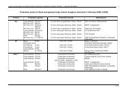
The relationships between slaughterhouses and their downstream activities are illustrated in a<br />
very simplified and general form in the figure below.<br />
FAT<br />
MELTING<br />
RENDERING<br />
BLOOD<br />
PROCESSING<br />
INCINERATION<br />
LANDFILL<br />
FERTILISER MANUFACTURE<br />
BURNING TALLOW AS<br />
A FUEL<br />
BONE<br />
PROCESSING<br />
SLAUGHTERING<br />
GELATINE<br />
MANUFACTURE<br />
GLUE<br />
MANUFACTURE<br />
FOOD/FEED PROCESSING<br />
TANNERIES<br />
BIOGAS PRODUCTION<br />
COMPOSTING<br />
Relationships between slaughterhouses and their downstream activities (summary)<br />
INCINERATION<br />
LANDFILL<br />
LAND INJECTION<br />
LAND SPREADING<br />
BIOGAS PRODUCTION<br />
COMPOSTING<br />
WASTE WATER<br />
TREATMENT<br />
Individual unit operations in slaughterhouses are described first. This section is divided<br />
between the slaughter of large animals and the slaughter of poultry. The processes at individual<br />
types of animal by-products installations are then described. Some waste water treatment<br />
processes that are applied in the industries are then described, firstly for slaughterhouses and<br />
then for animal by-products installations.<br />
Current consumption and emission levels (Chapter 3)<br />
The average live weights of animals and carcase weights vary considerably between Member<br />
States. Consumption and emission data has, to a large extent, been reported either “per tonne of<br />
carcase produced” or “per tonne of by-product treated”. This reflects the terminology of the<br />
Directive and makes it easier to compare information from different sources. It also enables the<br />
relationships between the actual processes and consumption and emission levels to be<br />
examined, at the same time as avoiding misleading information based on, e.g. low<br />
concentrations, which may be achieved by the overconsumption of water.<br />
Detailing the consumption and emission levels serves several purposes. Firstly, the ranges of<br />
levels for given processes and unit operations illustrate potential opportunities for improvement<br />
in environmental performance by those operating at the higher levels in the range. Secondly,<br />
the availability of data from unit operations also demonstrates that it is practicable to measure<br />
consumption and emission levels at that level and thus to monitor improvements. Thirdly, the<br />
information can also be used to identify priority unit operations which can be improved. Also,<br />
RHC/EIPPCB/SA_BREF_FINAL Version November 2003 iii
Executive Summary<br />
the availability of data at unit operation level makes it possible to compare techniques and<br />
determine BAT for those parts of processes where consumption and emission levels are<br />
significant and alternatives are available.<br />
The data reported in the BREF illustrate a wide range of performances in the industries. For<br />
example, for pig slaughterhouses a total water consumption range of 1600 – 8300 litres per<br />
tonne of carcase produced is reported in Table 3.2. Water consumption levels, either in ranges<br />
or single values, were also provided for the following unit operations: loading and vehicle<br />
washing; lairage; slaughter; bleeding; skin removal, scalding; hair and toenail removal;<br />
singeing; rind treatment; chilling; intestine washing and cleaning. Intestine washing was<br />
reported to use between 442 – 680 litres per tonne of carcase produced and to emit a BOD range<br />
of 0.98 - 3.25 kg per tonne of carcase and was therefore identified as a unit operation making a<br />
significant contribution to the pollution caused by the whole activity. Any contact between<br />
water and carcases or animal by-products leads to water contamination, which is one of the key<br />
environmental issues for slaughterhouses. The issue of reducing water consumption and water<br />
contamination, during intestine washing is addressed later in this document. Techniques are<br />
described and BAT is identified is identified in Section 5.2.1.<br />
Some of the data provided for slaughterhouses show the breakdown of how water and energy<br />
are consumed for different operations in an installation, as percentage values. This method of<br />
presenting data can be useful for identifying overall priorities, but it is less useful for monitoring<br />
improvements in a single operation because others may also change. For example, if less water<br />
is used for scalding then the percentage used in cleaning may rise even if the actual<br />
consumption does not. Nevertheless, this information has been useful, for confirming that<br />
cleaning as a major consumer of water and that refrigeration as a major consumer of energy, in<br />
slaughterhouses. The issue of minimising the consumption of water, and therefore the<br />
associated reduced contamination of waste water and the energy consumed to heat the water,<br />
has been addressed in this document. Unfortunately very little information has been received<br />
about reducing the energy consumed by chilling and refrigeration.<br />
Drying operations at animal by-products installations generally use most of the energy<br />
consumed. Information about consumption levels supports this. This issue has been addressed<br />
to some extent in the BREF and BAT has been identified for rendering.<br />
Most of the information provided about odour is qualitative and the measurements received<br />
have been presented using several units, which has made quantitative comparison between the<br />
problems and potential solutions impossible. Nevertheless, odour associated with the storage<br />
and processing of animal by-products is addressed from both the preventive and abatement<br />
perspectives and BAT have been identified.<br />
Most of the consumption and emission data provided for slaughterhouses and animal byproducts<br />
installations relates to waste water, although unfortunately most of the data<br />
submissions were not accompanied by descriptions of the processes and throughput data or the<br />
waste water treatments applied. Nevertheless, sufficient information was received for the<br />
technical working group (TWG) to conclude that BAT is to subject the effluent from<br />
slaughterhouses and animal by-products installations to a biological treatment process. BAT<br />
associated levels based on the expert judgment of the TWG are given in chapter 5 and are<br />
shown in the table below.<br />
For incineration, data on air emissions and ash analysis is reported both in this chapter and in<br />
the chapter 4. The TWG has agreed to BAT associated levels and these are reported in chapter<br />
5 and are shown in the table below.<br />
For some animal by-products activities, little or no consumption and emission level data was<br />
provided, however, qualitative information is included in the document.<br />
iv Version November 2003 RHC/EIPPCB/SA_BREF_FINAL
Executive Summary<br />
The collection of data at the unit operation level, using comparable monitoring techniques and<br />
accompanied with detailed descriptions of the technique and the operating conditions, would be<br />
very useful for the revision of the BREF.<br />
Techniques to consider in the determination of BAT (Chapter 4)<br />
Chapter 4 contains the detailed information used by the TWG to determine BAT for the<br />
slaughterhouses and animal by-products industries.<br />
About 250 techniques are described. They are described under the standard headings<br />
Description, Achieved environmental benefits, Cross-media effects, Operational data,<br />
Applicability, Economics, Driving force for implementation, Example plants and Reference<br />
literature. The TWG has aimed to include enough information to assess the applicability of the<br />
techniques in general or specific cases. The standard structure assists the comparison of<br />
techniques both qualitatively and quantitatively. The information in this chapter is essential to<br />
the determination of BAT.<br />
Those techniques which the TWG has judged to be BAT, are also cross-referenced from chapter<br />
5. Permit writers and installation operators are thus directed to the discussion of the technique<br />
associated with the BAT conclusions, which can assist them when they are determining the<br />
BAT-based conditions of IPPC permits.<br />
This chapter includes both “process-integrated” and “end-of-pipe” techniques, thus covering<br />
both pollution prevention and pollution control measures, respectively. Some of the techniques<br />
are very technical and others are good operating practices, including management techniques.<br />
The chapter is structured so that techniques which are generally applicable to all<br />
slaughterhouses and animal by-products installations are described first. These include general<br />
training, maintenance and operational good practice, considered as general techniques as they<br />
can be applied to virtually all activities. Others are more technical, but apply to the provision<br />
and use of utilities and services that are also applied in most industrial activities, such as<br />
providing lighting, or cleaning the installation. There are some techniques in this section which<br />
are more directly related to slaughterhouses and animal by-products installations, including<br />
several dealing with the storage of animal by-products and in particular the prevention of odour.<br />
Techniques associated with preventing the accidental release of large volumes of liquids and<br />
especially blood, are also included. General waste water treatment techniques are also included<br />
in this section.<br />
Techniques which apply to all slaughterhouses are then described. These deal with issues such<br />
as the cleaning of lorries delivering live animals; minimisation of water consumption and<br />
contamination on slaughter-lines; blood collection and the minimisation of water and energy use<br />
in knife sterilisation.<br />
The next 2 main sections contain techniques dealing with the slaughter of large animals and<br />
poultry, respectively. These include viscera and hide treatments undertaken at large animal<br />
slaughterhouses. The techniques address potential consumption and emission issues at the unit<br />
operation level, i.e. they are inherently “process-integrated” pollution prevention and control<br />
techniques. Some are technical and some are operational. Many of them address the key<br />
environmental issue of minimisation of water consumption and the associated contamination of<br />
waste water. In many cases there are energy considerations too, due to water being heated.<br />
They also address the minimisation of waste, e.g. associated with the trimming of hides.<br />
The final section on slaughterhouses includes techniques for cleaning, waste water treatment<br />
and waste treatment. Throughout the chapter there is an ongoing theme about preventing waste<br />
water contamination and the segregation of by-products to maximise their usability and<br />
minimise cross contamination and waste.<br />
RHC/EIPPCB/SA_BREF_FINAL Version November 2003 v
Executive Summary<br />
When the animal by-products industries are addressed there is an emphasis on minimising waste<br />
and odour problems. Where the individual processes are addressed one by one, techniques<br />
particular to the process in question are addressed, although in many cases the same<br />
environmental issues are discussed. For example, several of the techniques address energy<br />
saving for drying processes. Many of the techniques deal with “end-of-pipe” odour abatement<br />
and waste water treatment.<br />
The section on the incineration of animal by-products addresses those issues specific to the<br />
incineration of animal by-products, starting from their delivery to the site. Techniques which<br />
have no special relevance to animal by-products are not covered because they come within the<br />
scope of the “Waste Incineration” BREF. Issues such as flue gas treatment come within the<br />
scope of the “Waste Incineration” BREF whereas the main issues addressed by the techniques<br />
in this BREF are either directly or indirectly related to prevention of odour arising from animal<br />
by-products and the destruction of TSE risk material.<br />
Finally, 3 integrated same-site activities are described and the environmental advantages of, e.g.<br />
reduced energy consumption by re-using heat and odour destruction by on-site incinerators are<br />
described.<br />
Best available techniques (Chapter 5)<br />
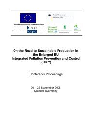
The way the BAT conclusions are presented in chapter 5 is shown in the figure below. In the<br />
figure, the BAT conclusions are presented in tiers. The top tier shows the Sections listing BAT<br />
for all slaughterhouses and animal by-products installations; the second is divided between<br />
additional BAT for slaughterhouses and BAT for animal by-products installations and the third<br />
is divided further showing the Sections listing additional BAT for individual types of<br />
slaughterhouse and animal by-products installation.<br />
The conclusions represent what the TWG considered to be BAT in a general sense for the<br />
slaughterhouses and animal by-products industries based upon the information in chapter 4 and<br />
taking account of the Article 2(11) definition of “best available techniques” and the<br />
considerations listed in Annex IV to the Directive. This chapter does not set emission limit<br />
values but suggests emission levels that are associated with the use of BAT.<br />
vi Version November 2003 RHC/EIPPCB/SA_BREF_FINAL
Tier 1<br />
Tier 2<br />
Tier 3<br />
5.2.1 ADDITIONAL BAT<br />
for the slaughter<br />
of large animals<br />
5.3.1<br />
ADDITIONAL<br />
BAT<br />
for fat melting<br />
5.1 BAT for slaughterhouses<br />
and animal by-products<br />
installations<br />
5.2 ADDITIONAL BAT<br />
for slaughterhouses<br />
5.3.2<br />
ADDITIONAL<br />
BAT<br />
for rendering<br />
5.2.2 ADDITIONAL BAT<br />
for the slaughter<br />
of poultry<br />
5.3.3<br />
ADDITIONAL<br />
BAT<br />
for fish-meal<br />
and fish-oil<br />
production<br />
5.3.4<br />
ADDITIONAL<br />
BAT<br />
for blood<br />
processing<br />
5.1.1 General<br />
processes<br />
and<br />
operations<br />
5.1.1.1 BAT for<br />
environmental<br />
management<br />
5.3.5<br />
ADDITIONAL<br />
BAT<br />
for bone<br />
processing<br />
5.1.2 Integration<br />
of same site<br />
activities<br />
5.3.6<br />
ADDITIONAL<br />
BAT<br />
for gelatine<br />
manufacture<br />
How the BAT conclusions are presented for slaughterhouses and animal by-products installations<br />
5.1.3 Collaboration<br />
with upstream and<br />
downstream<br />
activities<br />
5.3 ADDITIONAL BAT<br />
for animal by-products<br />
installations<br />
5.3.7<br />
ADDITIONAL<br />
BAT<br />
for incineration<br />
5.1.4 Installation<br />
and equipment<br />
cleaning<br />
5.3.8<br />
ADDITIONAL<br />
BAT<br />
for biogas<br />
production<br />
Executive Summary<br />
5.1.5 Treatment<br />
of waste water<br />
5.3.9<br />
ADDITIONAL<br />
BAT<br />
for composting<br />
RHC/EIPPCB/SA_BREF_FINAL Version November 2003 vii
Executive Summary<br />
BAT addressing the main environmental issues for slaughterhouses and animal by-products<br />
installations have been identified, to the extent that the information provided during the<br />
information exchange has allowed. The assessment of techniques is dependent on the<br />
information provided and assessed by the TWG. For many techniques there is only limited<br />
technical and economic data available. For some key environmental issues very little<br />
information was provided.<br />
For slaughterhouses, the key environmental issues are generally water consumption; the<br />
emission of high organic strength liquids to water and the energy consumption associated with<br />
refrigeration and heating water. For animal by-products installations, the main issues are related<br />
to the energy consumption associated with drying animal by-products; the emission of high<br />
strength organic liquids to water; infectivity, especially related to the controlling, the handling<br />
and the destruction of TSE material and odour.<br />
Measures to minimise consumption and emission levels are very much influenced by planning<br />
each process technically and operationally at each unit operation level. Some BAT therefore,<br />
relate to this.<br />
Regulation (EC) No 1774/2002 of the European Parliament and of the Council of 3 October<br />
2002 laying down health rules concerning animal by-products not intended for human<br />
consumption specifies requirements for the handling, storage, transport and processing of<br />
animal by-products and describes the disposal routes allowed for TSE risk material. Care has<br />
been taken to ensure that the BAT conclusions do not conflict with the requirements of this<br />
Regulation. Likewise care has been taken to ensure consistency with other legislation relating<br />
to, e.g. public health, food safety, animal welfare and health and safety at work. A great deal of<br />
the discussion about the BAT conclusions examined the potential impact of the use of<br />
techniques on these issues.<br />
The following paragraphs summarise the key BAT conclusions relating to the most relevant<br />
environmental issues. During the discussion of the information exchanged by the TWG, many<br />
issues were raised and discussed. Only some of them are highlighted in this summary and it<br />
should not be read instead of the “Best available techniques” chapter, which should not be read<br />
in isolation from the rest of the BREF.<br />
General management and operation<br />
BAT options related to general management and operational techniques contribute to the overall<br />
minimisation of consumption and emission levels, by providing systems of work which<br />
encourage good practice and raise awareness. The BAT identified focus on issues such as using<br />
an environmental management system; providing training; using a planned maintenance<br />
programme; implementing energy, refrigeration, light and noise management systems;<br />
managing and minimising the quantities of water and detergents consumed and, in<br />
slaughterhouses, managing and monitoring the use of hot water.<br />
Water consumption and the emission of high organic strength liquids in waste water<br />
It is recognised that minimising water consumption and contamination has wide reaching<br />
environmental benefits, beyond just that. Increasing the volume of water used automatically<br />
affects the volume of waste water which has to be treated at either an on-site or a municipal<br />
waste water treatment plant. The treatment of waste water consumes energy and sometimes<br />
chemicals and it can lead to odour problems. Every time water makes contact with a carcase or<br />
any animal by-product, whether during production or cleaning, contaminants such as fats or<br />
blood are entrained and these increase the burden on the waste water treatment plant. In many<br />
cases the water used is hot, so energy will have been used to heat it. Also the fats can melt in<br />
hot water and then become more difficult to separate from the water.<br />
The availability of water varies depending on factors such as climate, hydrogeology, other<br />
demands for its use and price. Whether consumption is considered to be a key environmental<br />
issue at site level may, therefore, vary. The Water Framework Directive requires that water<br />
viii Version November 2003 RHC/EIPPCB/SA_BREF_FINAL
Executive Summary<br />
pricing policies provide adequate incentives for users to use water resources efficiently. The<br />
BREF identifies BAT to minimise water consumption.<br />
Some examples of the type of BAT conclusions reached are included in the following list,<br />
although this is only a summary and there are more in the BAT chapter. BAT is to remove all<br />
running water hoses and repair dripping taps and toilets; fit and use drains with screens and/or<br />
traps to prevent solid material from entering the waste water; dry clean vehicles and installations<br />
before cleaning with a high-pressure hoses fitted with hand-operated triggers; use a squeegee for<br />
the initial cleaning of the blood collection trough; where the equipment is suitable, operate a<br />
cleaning-in-place system; avoid carcase washing and where this is not possible to minimise it,<br />
combined with clean slaughter techniques; re-use cold water within pig de-hairing machines; reuse<br />
cooling water from pig singeing kilns; empty stomachs and small intestines dry; remove<br />
carcase washing equipment from poultry slaughter-lines except after de-feathering and<br />
evisceration and use recycled water, e.g. from the scalding tank, for the carriage of feathers.<br />
Some of the techniques apply to all slaughterhouses and animal by-products installations and<br />
others are applicable in e.g. only in large animal or only in poultry slaughterhouses. Many, but<br />
not all, of the techniques applicable to animal by-products installations are waste water<br />
treatment techniques to clean water which has been contaminated by the process, e.g. during<br />
rendering; fish-meal and fish-oil manufacture or gelatine manufacture. Waste water treatment<br />
techniques are listed.<br />
Energy<br />
Power generation has major global implications, due to the emissions of greenhouse gases from<br />
large combustion plants, so minimising energy consumption, including the use of hot water is a<br />
key issue to be addressed. Hygiene standards have always been paramount in slaughterhouses<br />
and to a great extent in animal by-products installations producing food or pharmaceutical grade<br />
products. The Regulation (EC) No 1774/2002 of the European Parliament and of the Council<br />
of 3 October 2002 laying down health rules concerning animal by-products not intended for<br />
human consumption has increased the emphasis on hygiene, at all animal by-products<br />
installations, to protect the food and feed chain and to control the risk to public health. Some<br />
examples of the types of relevant BAT which have been identified include: dry clean<br />
installations and transport by-products dry, followed by pressure cleaning using hoses fitted<br />
with hand-operated triggers and where the use of hot water is necessary, using thermostatically<br />
controlled steam and water valves; insulating and covering knife sterilisers and insulating<br />
scalding tanks and the steam scalding of pigs and poultry.<br />
In animal by-products installations carrying out fat melting, rendering, fish-meal and fish-oil<br />
production, blood processing, bone processing, gelatine manufacturing or glue making the<br />
majority of the energy consumed is generally associated with the drying process. For example<br />
2/3 of the energy consumed in a rendering plant may be directly due to drying. Some examples<br />
of the types of BAT techniques identified include: rationalising and insulating steam and water<br />
pipework; removing water from blood, by steam coagulation, prior to rendering; for raw<br />
material throughputs less than 50000 t/yr, to use a single effect evaporator and for raw material<br />
throughputs greater than, or equal to 50000 t/yr, to use a multiple-effect evaporator, to remove<br />
water from liquid mixtures and to concentrate plasma, prior to spray drying, using reverse<br />
osmosis, vacuum evaporation or by steam coagulation.<br />
In slaughterhouses, in particular, refrigeration is a very large consumer of energy. It may also<br />
be significant where animal by-products are kept in refrigerated storage prior to treatment at<br />
animal by-products installations. Although this was identified as a key environmental issue,<br />
very little information was provided to assist with the determination of BAT. Some general<br />
BAT have been identified, including: implementing refrigeration management systems;<br />
operating controls over refrigeration plant running times; fitting and operating chill room door<br />
closing switches and recuperating heat from refrigeration plants.<br />
RHC/EIPPCB/SA_BREF_FINAL Version November 2003 ix
Executive Summary<br />
Infectivity<br />
Infectivity was identified as a key environmental issue, principally due to the concerns arising<br />
from the BSE crises regarding both animal health, especially with respect to the feed and food<br />
chain and human health after the links between TSE in animals and CJD, in humans were<br />
discovered. Control of the handling and treatment of confirmed TSE infected materials, those<br />
suspected of being infected and those arising from animals killed in the context of TSE<br />
eradication measures is regulated by Regulation (EC) No 1774/2002 of the European<br />
Parliament and of the Council of 3 October 2002 laying down health rules concerning animal<br />
by-products not intended for human consumption.<br />
The BREF contains BAT conclusions both directly and indirectly associated with the prevention<br />
of the spread of TSE and the destruction of TSE risk materials. These are particularly related to<br />
rendering and incineration. For example, BAT is to do the following: continuously collect byproducts<br />
dry and segregated from each other, along the length of the slaughter-line and<br />
throughout animal by-products treatment; optimise bleeding and the collection of blood; use<br />
sealed, storage, handling and charging facilities for animal by-products; enclose any buildings<br />
used for delivery storage, handling and processing of animal by-products; clean and disinfect<br />
delivery vehicles and equipment, after each delivery/use; reduce in size animal carcases and<br />
parts of animal carcases, before incineration; restrict feedstock to exactly that tested during<br />
trials; operate continuous incineration; operate an ash burnout chamber, where adequate<br />
combustion is not otherwise achievable, e.g. immediately downstream from rotary kilns; operate<br />
a monitoring regime for emissions, including a protocol for monitoring burnout, including<br />
biohazard from TSE prions, in ash; to achieve emission levels as low as reasonably practicable<br />
below those shown in the table below. This table includes BAT associated levels for total<br />
carbon and total protein, in ash.<br />
Odour<br />
Although odour is widely considered to be an issue of local nuisance, it can in reality be the<br />
most troublesome day to day environmental problem for slaughterhouses and animal byproducts<br />
installations and so it has to be controlled. Typically it will be caused by the<br />
decomposition of animal by-products and this has other related environmental consequences,<br />
e.g. it reduces the usability of the animal by-products and hence increases waste. Also, the<br />
substances causing odour can cause problems during waste water treatment.<br />
Odour has been considered in detail by the TWG and BAT has been identified to minimise<br />
odour and to destroy it when prevention has not been possible. The main conclusion was that<br />
animal by-products should be used or disposed of as soon as possible after the animal is<br />
slaughtered. Preservation techniques to prevent decomposition and to minimise the formation<br />
of malodorous substances and abatement techniques incur significant cross-media effects,<br />
including energy consumption and often they require significant economic investment and<br />
running costs. Taking account of the cross-media effects and their global implications and the<br />
economic factors, the TWG concluded that BAT is to implement some such techniques, but<br />
only if the animal by-products cannot be treated before the malodorous substances form, if the<br />
animal by-products are inherently malodorous or if the process is inherently malodorous.<br />
Some examples of the BAT identified include: store animal by-products for short periods and<br />
possibly to refrigerate them; where it is not possible to treat blood or other animal by-products<br />
before their decomposition starts to cause odour problems and/or quality problems, refrigerating<br />
them as quickly as possible and for as short a time as possible, to minimise decomposition;<br />
where inherently malodorous substances are used or are produced during the treatment of<br />
animal by-products, to pass the low intensity/high volume gases through a biofilter. For<br />
rendering, when it has been impossible to use fresh raw materials and thereby to minimise the<br />
production of malodorous substances, BAT is to do either of the following: to, burn the noncondensable<br />
gases in an existing boiler and to pass the low intensity/high volume odours<br />
through a biofilter or to burn the whole vapour gases in a thermal oxidiser and to pass the low<br />
intensity/high volume odours through a biofilter. For fish-meal and fish-oil production, BAT is<br />
to use fresh, (low total volatile nitrogen) feedstock and incinerate malodorous air, with heat<br />
x Version November 2003 RHC/EIPPCB/SA_BREF_FINAL
Executive Summary<br />
recovery. For incineration of animal by-products, some examples of BAT include, to duct air<br />
from the installation and the pre-combustion equipment to combustion chambers, operate odour<br />
arrestment techniques, when the incinerator is not working, when odour prevention is not<br />
reasonably practicable and use a carbon filter for odour abatement, when incinerators are not<br />
operating.<br />
Collaboration with upstream and downstream activities<br />
The operations of those involved in the supply of animals to slaughterhouses, including the<br />
farmers and the hauliers, can have environmental consequences in the slaughterhouse. The<br />
suppliers of feedstock to animal-by-products installations and other downstream users can also<br />
influence the environmental impact of those installations. Their impact can be affected by the<br />
properties of the feedstock, e.g. the freshness, degree of separation of different materials and the<br />
specification.<br />
BAT is to seek collaboration with upstream partners, to create a chain of environmental<br />
responsibility, to minimise pollution and to protect the environment as a whole. Several BAT<br />
are identified and most of these are associated with the delivery and feeding of animals or the<br />
storage of animal by-products.<br />
Sites with more than one activity<br />
Several examples have been identified where sites with more than one activity can collaborate<br />
to minimise consumption and emission levels. BAT is to re-use heat and/or power produced in<br />
one activity in other activities and to share abatement techniques, where these are required, e.g.<br />
for waste water or odour treatment.<br />
Three examples are listed in the BREF, but the principle can probably be applied to any samesite<br />
activities, of which there are many, for instance, slaughterhouses may, e.g. be on the same<br />
site as fat melting plants, rendering plants, blood processing plants, incinerators and composting<br />
plants.<br />
It is also very common for slaughterhouses to have meat cutting plants and further processing<br />
plants on the same site. In such cases information from the “Food, drink and milk” BREF can<br />
be used to identify opportunities for collaboration.<br />
The TWG also concluded that BAT is to export any heat and/or power produced which cannot<br />
be used on-site<br />
BAT associated levels<br />
BAT associated levels were identified for waste water treatment and for the incineration of<br />
animal by-products.<br />
The emission levels given below are generally considered to be appropriate for protecting the<br />
water environment and are indicative of the emission levels that would be achieved when<br />
applying those techniques generally considered to represent BAT. They do not necessarily<br />
represent levels currently achieved within the industry but are based on the expert judgment of<br />
the TWG.<br />
Parameter<br />
Achievable<br />
COD BOD5 SS Nitrogen<br />
(total)<br />
Phosphorus<br />
(total)<br />
FOG<br />
emission<br />
level (mg/l)<br />
25 - 125 10 - 40 5 - 60 15 – 40 2 - 5 2.6 - 15<br />
Emission levels associated with BAT for minimising waste water emissions from slaughterhouses and animal<br />
by-products installations<br />
RHC/EIPPCB/SA_BREF_FINAL Version November 2003 xi
Executive Summary<br />
BAT for the incineration of animal by-products, is to achieve emission levels as low as<br />
reasonably practicable below those shown in the table below.<br />
Releases to air Performance associated with BAT (3)<br />
Typical Monitoring<br />
SO2 (mg/m 3 ) < 30 (2)<br />
Continuous<br />
HCl (mg/m 3 ) < 10 (2)<br />
Continuous<br />
HF (mg/m 3 ) n/a<br />
NOx (mg/m 3 ) < 175 (2)<br />
Continuous<br />
CO (mg/m 3 ) < 25 (2)<br />
Continuous<br />
VOCs (mg/m 3 ) < 10 (2)<br />
Periodic<br />
Dust (mg/m 3 ) < 10 (2)<br />
Continuous<br />
Dioxins and furans (ng/m 3 ) < 0.1 (4)<br />
Periodic<br />
Heavy metals total (Cd, TI) (mg/m 3 ) < 0.05 (5)<br />
Heavy metals (Hg) (mg/m 3 ) < 0.05 (5)<br />
Heavy metals total<br />
(Sb, As, Pb, Cr, Co, Cu, Mn, Ni, V)<br />
(mg/m 3 ) < 0.5 (5)<br />
NH3 (mg/m 3 ) < 10<br />
Residence time >850 ºC 3.5 s<br />
Oxygen (minimum after last injection) 9 % Continuous<br />
Pressure, Temperature, Water vapour; Volumetric flow Continuous<br />
Ash - (total carbon) < 1 % (6)<br />
Periodic<br />
Ash – (total protein) (Aqueous extract) (mg/100g) 0.3 – 0.6 Periodic<br />
(2)<br />
Releases control – “95 % percentile hourly average over 24 hours”. Measurements at 273 K (temp.),<br />
101.3 kPa (pressure) and 11 % O2 dry gas<br />
(3)<br />
Actual performance results operating a dry flue gas-cleaning system with bag filters and injected<br />
reagents<br />
Values measured over a sample period of a minimum of 6 hours and a maximum of 8 hours expressed<br />
as toxic equivalent in accordance with Annex 1 of the Waste Incineration Directive<br />
(5)<br />
Values measured over a sample period of a minimum of 6 hours and a maximum of 8 hours<br />
(6)<br />
Total organic carbon<br />
Note: Protein analysis is not relevant to the dedicated incineration of poultry by-products<br />
Emission levels associated with the dedicated incineration of animal by-products in either bubbling<br />
fluidised bed, circulating fluidised bed or rotary kiln incinerators<br />
Emerging techniques (Chapter 6)<br />
Chapter 6 includes 2 techniques that have not yet been commercially applied and are still in the<br />
research or development phase. They are “Bio-refining of animal by-products to produce soil<br />
improvers and fertilisers” and “Biotechnological treatment of animal by-products in order to<br />
increase energetic valorisation”. They have been included here to raise awareness for any future<br />
revision of this document.<br />
Concluding remarks (Chapter 7)<br />
Information provided<br />
Many reports from industry and Member State authorities were used as sources of information<br />
in the drafting of this BREF and these were supplemented by information from individuals<br />
based on example plants. A great deal of information was received during and following site<br />
visits to slaughterhouses and animal by-products installations in several Member States. The<br />
formal consultations on each draft of the document also prompted the provision of a huge<br />
amount of information as well as providing the main opportunities for the TWG to verify the<br />
information already submitted.<br />
xii Version November 2003 RHC/EIPPCB/SA_BREF_FINAL
Executive Summary<br />
Although over 350 pieces of information were provided, some significant gaps remain. Energy<br />
consumption is a key environmental issue in slaughterhouses, due to chilling and refrigerated<br />
storage and in many animal by-products installations, especially during drying. In spite of this,<br />
very little data or information about energy saving techniques was submitted.<br />
There is a lack of consistency in the data on the measurement of odour and the identification of<br />
the options for keeping odour streams separate for treatment. Prevention of odour is addressed,<br />
however, albeit qualitatively.<br />
In general the consumption and emission data provided was not well explained in terms of<br />
operating conditions and analytical methods and its relationship with the techniques described<br />
was not always made clear. This is one of the reasons why there are very few associated BAT<br />
levels quoted. The TWG attempted to collect data “per tonne of carcase produced” and “per<br />
tonne of animal by-product treated” for each unit operation, to allow direct comparisons to be<br />
made and to identify the areas with high consumption and emission levels, so that these could<br />
be addressed. Large gaps remain in this data.<br />
Very little information was received about bone processing, glue manufacture, gasification of<br />
meat and bone meal, land spreading/injection, shellfish shell cleaning and the manufacture of<br />
fertiliser from animal meal. This may in some cases be due to local legislation prohibiting or<br />
restricting the application of animal by-products to land and restrictions under the new<br />
Regulation (EC) No 1774/2002 of the European Parliament and of the Council of 3 October<br />
2002 laying down health rules concerning animal by-products not intended for human<br />
consumption.<br />
Driving forces<br />
The content of the BREF, as well as its time-scale for preparation has been strongly influenced<br />
by issues such as food and feed safety concerns, e.g. arising from BSE; food hygiene and animal<br />
welfare. The focus has remained on the prevention and control of pollution, but care has been<br />
taken to ensure there is consistency with legislation and good practice associated with these<br />
other important drivers. The main legal driver has been the new Regulation (EC) No 1774/2002<br />
of the European Parliament and of the Council of 3 October 2002 laying down health rules<br />
concerning animal by-products not intended for human consumption.<br />
Level of consensus<br />
The conclusions of the BREF were agreed at the final TWG meeting and there are no split<br />
views.<br />
Recommendations for future work<br />
The gaps in the information indicate areas where future work could provide results which might<br />
assist in the identification of BAT when the BREF is revised, thereby helping operators and<br />
permit writers to protect the environment as a whole.<br />
The lack of data “per tonne of carcase produced” and “per tonne of animal by-product treated”,<br />
for each unit operation, could be addressed via the regulatory authorities and the various<br />
industry NGOs which represent the slaughterhouses and animal by-products operators. They<br />
could encourage and co-ordinate the increased measurement of consumption and emission<br />
levels at the unit operation level, including details on operating conditions; descriptions of<br />
techniques applied; sampling protocols; analytical methods and statistical presentation.<br />
A great deal of the information provided about techniques was incomplete. The TWG decided<br />
that although there was insufficient information in these techniques to help with the<br />
determination of BAT, they should still be included in the document. The incomplete<br />
techniques are appended to chapter 7. They are included to provoke both the collection and<br />
provision of further information, when the BREF is revised.<br />
RHC/EIPPCB/SA_BREF_FINAL Version November 2003 xiii
Executive Summary<br />
Suggested topics for future R & D projects<br />
The following topics might be considered for future research and development projects:<br />
1 minimisation of energy consumption associated with chilling and refrigerated storage<br />
2 minimisation of energy consumption associated with the drying of animal by-products<br />
3 opportunities to use non-potable water at slaughterhouses, without compromising<br />
hygiene and food safety<br />
4 optimisation of the use of animal by-products, to minimise waste and<br />
5 the development of benchmarking tools to improve the quality of future information<br />
exchanges and revisions of the BREF.<br />
xiv Version November 2003 RHC/EIPPCB/SA_BREF_FINAL
PREFACE<br />
1. Status of this document<br />
Preface<br />
Unless otherwise stated, references to “the Directive” in this document means the Council<br />
Directive 96/61/EC on integrated pollution prevention and control. As the Directive applies<br />
without prejudice to Community provisions on health and safety at the workplace, so does this<br />
document.<br />
This document is a working draft of the European IPPC Bureau. It is not an official publication<br />
of the European Communities and does not necessarily reflect the position of the European<br />
Commission.<br />
2. Relevant legal obligations of the IPPC Directive and the definition of BAT<br />
In order to help the reader understand the legal context in which this document has been drafted,<br />
some of the most relevant provisions of the IPPC Directive, including the definition of the term<br />
“best available techniques”, are described in this preface. This description is inevitably<br />
incomplete and is given for information only. It has no legal value and does not in any way alter<br />
or prejudice the actual provisions of the Directive.<br />
The purpose of the Directive is to achieve integrated prevention and control of pollution arising<br />
from the activities listed in its Annex I, leading to a high level of protection of the environment<br />
as a whole. The legal basis of the Directive relates to environmental protection. Its<br />
implementation should also take account of other Community objectives such as the<br />
competitiveness of the Community’s industry thereby contributing to sustainable development.<br />
More specifically, it provides for a permitting system for certain categories of industrial<br />
installations requiring both operators and regulators to take an integrated, overall look at the<br />
polluting and consuming potential of the installation. The overall aim of such an integrated<br />
approach must be to improve the management and control of industrial processes so as to ensure<br />
a high level of protection for the environment as a whole. Central to this approach is the general<br />
principle given in Article 3 that operators should take all appropriate preventative measures<br />
against pollution, in particular through the application of best available techniques enabling<br />
them to improve their environmental performance.<br />
The term “best available techniques” is defined in Article 2(11) of the Directive as “the most<br />
effective and advanced stage in the development of activities and their methods of operation<br />
which indicate the practical suitability of particular techniques for providing in principle the<br />
basis for emission limit values designed to prevent and, where that is not practicable, generally<br />
to reduce emissions and the impact on the environment as a whole.” Article 2(11) goes on to<br />
clarify further this definition as follows:<br />
“techniques” includes both the technology used and the way in which the installation is<br />
designed, built, maintained, operated and decommissioned;<br />
“available” techniques are those developed on a scale which allows implementation in the<br />
relevant industrial sector, under economically and technically viable conditions, taking into<br />
consideration the costs and advantages, whether or not the techniques are used or produced<br />
inside the Member State in question, as long as they are reasonably accessible to the operator;<br />
“best” means most effective in achieving a high general level of protection of the environment<br />
as a whole.<br />
Furthermore, Annex IV of the Directive contains a list of “considerations to be taken into<br />
account generally or in specific cases when determining best available techniques ... bearing in<br />
mind the likely costs and benefits of a measure and the principles of precaution and prevention”.<br />
RHC/EIPPCB/SA_BREF_FINAL Version November 2003 xv
Preface<br />
These considerations include the information published by the Commission pursuant to Article<br />
16(2).<br />
Competent authorities responsible for issuing permits are required to take account of the general<br />
principles set out in Article 3 when determining the conditions of the permit. These conditions<br />
must include emission limit values, supplemented or replaced where appropriate by equivalent<br />
parameters or technical measures. According to Article 9(4) of the Directive, these emission<br />
limit values, equivalent parameters and technical measures must, without prejudice to<br />
compliance with environmental quality standards, be based on the best available techniques,<br />
without prescribing the use of any technique or specific technology, but taking into account the<br />
technical characteristics of the installation concerned, its geographical location and the local<br />
environmental conditions. In all circumstances, the conditions of the permit must include<br />
provisions on the minimisation of long-distance or transboundary pollution and must ensure a<br />
high level of protection for the environment as a whole.<br />
Member States have the obligation, according to Article 11 of the Directive, to ensure that<br />
competent authorities follow or are informed of developments in best available techniques.<br />
3. Objective of this Document<br />
Article 16(2) of the Directive requires the Commission to organise “an exchange of information<br />
between Member States and the industries concerned on best available techniques, associated<br />
monitoring and developments in them”, and to publish the results of the exchange.<br />
The purpose of the information exchange is given in recital 25 of the Directive, which states that<br />
“the development and exchange of information at Community level about best available<br />
techniques will help to redress the technological imbalances in the Community, will promote<br />
the worldwide dissemination of limit values and techniques used in the Community and will<br />
help the Member States in the efficient implementation of this Directive.”<br />
The Commission (Environment DG) established an information exchange forum (IEF) to assist<br />
the work under Article 16(2) and a number of technical working groups have been established<br />
under the umbrella of the IEF. Both IEF and the technical working groups include<br />
representation from Member States and industry as required in Article 16(2).<br />
The aim of this series of documents is to reflect accurately the exchange of information which<br />
has taken place as required by Article 16(2) and to provide reference information for the<br />
permitting authority to take into account when determining permit conditions. By providing<br />
relevant information concerning best available techniques, these documents should act as<br />
valuable tools to drive environmental performance.<br />
4. Information Sources<br />
This document represents a summary of information collected from a number of sources,<br />
including in particular the expertise of the groups established to assist the Commission in its<br />
work, and verified by the Commission services. All contributions are gratefully acknowledged.<br />
5. How to understand and use this document<br />
The information provided in this document is intended to be used as an input to the<br />
determination of BAT in specific cases. When determining BAT and setting BAT-based permit<br />
conditions, account should always be taken of the overall goal to achieve a high level of<br />
protection for the environment as a whole.<br />
The rest of this section describes the type of information that is provided in each section of the<br />
document.<br />
xvi Version November 2003 RHC/EIPPCB/SA_BREF_FINAL
Preface<br />
Chapters 1 and 2 provide general information on the slaughterhouses and animal by-products<br />
industries on the industrial processes used within the sector. Chapter 3 provides data and<br />
information concerning current emission and consumption levels reflecting the situation in<br />
existing installations at the time of writing.<br />
Chapter 4 describes in more detail the emission reduction and other techniques that are<br />
considered to be most relevant for determining BAT and BAT-based permit conditions. This<br />
information includes the consumption and emission levels considered achievable by using the<br />
technique, some idea of the costs and the cross-media issues associated with the technique, and<br />
the extent to which the technique is applicable to the range of installations requiring IPPC<br />
permits, for example new, existing, large or small installations. Techniques that are generally<br />
seen as obsolete are not included.<br />
Chapter 5 presents the techniques and the emission and consumption levels that are considered<br />
to be compatible with BAT in a general sense. The purpose is thus to provide general<br />
indications regarding the emission and consumption levels that can be considered as an<br />
appropriate reference point to assist in the determination of BAT-based permit conditions or for<br />
the establishment of general binding rules under Article 9(8). It should be stressed, however,<br />
that this document does not propose emission limit values. The determination of appropriate<br />
permit conditions will involve taking account of local, site-specific factors such as the technical<br />
characteristics of the installation concerned, its geographical location and the local<br />
environmental conditions. In the case of existing installations, the economic and technical<br />
viability of upgrading them also needs to be taken into account. Even the single objective of<br />
ensuring a high level of protection for the environment as a whole will often involve making<br />
trade-off judgements between different types of environmental impact, and these judgements<br />
will often be influenced by local considerations.<br />
Although an attempt is made to address some of these issues, it is not possible for them to be<br />
considered fully in this document. The techniques and levels presented in chapter 5 will<br />
therefore not necessarily be appropriate for all installations. On the other hand, the obligation to<br />
ensure a high level of environmental protection including the minimisation of long-distance or<br />
transboundary pollution implies that permit conditions cannot be set on the basis of purely local<br />
considerations. It is therefore of the utmost importance that the information contained in this<br />
document is fully taken into account by permitting authorities.<br />
Since the best available techniques change over time, this document will be reviewed and<br />
updated as appropriate. All comments and suggestions should be made to the European IPPC<br />
Bureau at the Institute for Prospective Technological Studies at the following address:<br />
Edificio Expo, c/ Inca Garcilaso, s/n, E-41092 Seville, Spain<br />
Telephone: +34 95 4488 284<br />
Fax: +34 95 4488 426<br />
e-mail: eippcb@jrc.es<br />
Internet: http://eippcb.jrc.es<br />
RHC/EIPPCB/SA_BREF_FINAL Version November 2003 xvii
Reference Document on Best Available Techniques in the<br />
<strong>Slaughterhouses</strong> and Animal By-products Industries<br />
EXECUTIVE SUMMARY ........................................................................................................................ I<br />
PREFACE ...............................................................................................................................................XV<br />
SCOPE............................................................................................................................................. XXXIII<br />
1 GENERAL INFORMATION ...........................................................................................................1<br />
1.1 The slaughtering industry in the European Union ......................................................................1<br />
1.2 The animal by-products industry in the European Union.........................................................10<br />
1.2.1 Fat melting......................................................................................................................11<br />
1.2.2 Rendering .......................................................................................................................11<br />
1.2.3 Fish-meal and fish-oil production...................................................................................12<br />
1.2.4 Blood processing ............................................................................................................13<br />
1.2.5 Gelatine manufacture......................................................................................................14<br />
1.2.6 Dedicated incineration of carcases, parts of carcases and animal meal..........................14<br />
1.2.7 Burning of tallow............................................................................................................15<br />
1.2.8 Land spreading/injection ................................................................................................15<br />
1.2.9 Biogas production...........................................................................................................15<br />
1.2.10 Composting ....................................................................................................................16<br />
1.3 Key environmental issues.........................................................................................................16<br />
1.3.1 <strong>Slaughterhouses</strong>..............................................................................................................16<br />
1.3.2 Animal by-products installations....................................................................................18<br />
1.3.2.1 General information about key environmental issues.....................................................18<br />
1.3.2.2 Fat melting......................................................................................................................18<br />
1.3.2.3 Rendering .......................................................................................................................19<br />
1.3.2.4 Fish-meal and fish-oil production...................................................................................19<br />
1.3.2.5 Blood processing ............................................................................................................20<br />
1.3.2.6 Gelatine manufacture......................................................................................................20<br />
1.3.2.7 Glue manufacture ...........................................................................................................20<br />
1.3.2.8 Dedicated incineration of carcases .................................................................................21<br />
1.3.2.9 Dedicated incineration of animal meal...........................................................................21<br />
1.3.2.10 Burning of tallow....................................................................................................22<br />
1.3.2.11 Land spreading/injection ........................................................................................22<br />
1.3.2.12 Biogas production...................................................................................................22<br />
1.3.2.13 Composting.............................................................................................................23<br />
1.4 Economic overview ..................................................................................................................23<br />
1.4.1 <strong>Slaughterhouses</strong> and animal by-products .......................................................................23<br />
1.4.2 The economic cost of consumption and emissions.........................................................25<br />
1.5 Food and veterinary legislation influences ...............................................................................27<br />
2 APPLIED PROCESSES AND TECHNIQUES.............................................................................29<br />
2.1 Slaughter...................................................................................................................................29<br />
2.1.1 Activities described in this chapter.................................................................................29<br />
2.1.2 Slaughter of large animals ..............................................................................................29<br />
2.1.2.1 Animal reception and lairage..........................................................................................30<br />
2.1.2.2 Slaughter.........................................................................................................................31<br />
2.1.2.3 Bleeding .........................................................................................................................32<br />
2.1.2.4 Hide and skin removal....................................................................................................33<br />
2.1.2.5 Head and hoof removal for cattle and sheep ..................................................................34<br />
2.1.2.6 Pig scalding ....................................................................................................................34<br />
2.1.2.7 Pig hair and toenail removal...........................................................................................35<br />
2.1.2.8 Pig singeing ....................................................................................................................35<br />
2.1.2.9 Rind treatment ................................................................................................................35<br />
2.1.2.10 Evisceration ............................................................................................................36<br />
2.1.2.11 Splitting ..................................................................................................................36<br />
2.1.2.12 Chilling...................................................................................................................37<br />
2.1.2.13 Associated downstream activities - viscera and hide and skin treatments..............38<br />
2.1.3 Slaughter of poultry........................................................................................................41<br />
RHC/EIPPCB/SA_BREF_FINAL Version November 2003 xix
2.1.3.1 Reception of birds.......................................................................................................... 41<br />
2.1.3.2 Stunning and bleeding....................................................................................................41<br />
2.1.3.3 Scalding ......................................................................................................................... 42<br />
2.1.3.4 De-feathering ................................................................................................................. 42<br />
2.1.3.5 Evisceration ................................................................................................................... 43<br />
2.1.3.6 Chilling .......................................................................................................................... 43<br />
2.1.3.7 Maturation...................................................................................................................... 44<br />
2.1.4 Slaughterhouse cleaning ................................................................................................ 44<br />
2.1.5 Storage of slaughterhouse by-products .......................................................................... 45<br />
2.2 Animal by-products installations .............................................................................................46<br />
2.2.1 Fat melting ..................................................................................................................... 46<br />
2.2.2 Rendering....................................................................................................................... 50<br />
2.2.2.1 Rendering of carcases and waste.................................................................................... 53<br />
2.2.2.2 Rendering of feathers and pig hair................................................................................. 56<br />
2.2.3 Fish-meal and fish-oil production .................................................................................. 57<br />
2.2.4 Bone processing............................................................................................................. 61<br />
2.2.5 Blood processing - plasma and dried red cell production .............................................. 61<br />
2.2.6 Gelatine manufacture ..................................................................................................... 64<br />
2.2.7 Glue manufacture...........................................................................................................82<br />
2.2.8 Dedicated incineration of carcases and parts of carcases and of meat and bone meal... 82<br />
2.2.8.1 Dedicated incineration of carcases and parts of carcases............................................... 82<br />
2.2.8.2 Dedicated incineration of animal meal........................................................................... 85<br />
2.2.8.3 Gasification of meat and bone meal............................................................................... 87<br />
2.2.9 Burning of tallow ........................................................................................................... 88<br />
2.2.10 Landfill and land spreading/injection............................................................................. 88<br />
2.2.11 Biogas production .......................................................................................................... 88<br />
2.2.12 Composting.................................................................................................................... 90<br />
2.3 Waste water treatments used at slaughterhouses and animal by-products installations ........... 93<br />
2.3.1 Slaughterhouse waste water treatment ........................................................................... 93<br />
2.3.1.1 Primary slaughterhouse waste water treatment.............................................................. 96<br />
2.3.1.2 Secondary slaughterhouse waste water treatment.......................................................... 97<br />
2.3.1.3 Tertiary slaughterhouse waste water treatment.............................................................. 99<br />
2.3.2 Animal by-product installation waste water treatment................................................... 99<br />
2.3.2.1 Rendering waste water treatment................................................................................... 99<br />
2.3.2.1.1 Mechanical waste water treatment ....................................................................... 100<br />
2.3.2.1.2 Physico-chemical treatment ................................................................................. 100<br />
2.3.2.1.3 Biological treatment............................................................................................. 101<br />
2.3.2.1.4 Feathers - elimination of hydrogen sulphide........................................................ 101<br />
2.3.2.2 Fish-meal and fish-oil manufacturing waste water treatment ...................................... 101<br />
2.3.2.3 Blood processing waste water treatment...................................................................... 101<br />
2.3.2.4 Gelatine manufacture waste water treatment ............................................................... 102<br />
3 CURRENT CONSUMPTION AND EMISSION LEVELS ....................................................... 103<br />
3.1 <strong>Slaughterhouses</strong> ..................................................................................................................... 103<br />
3.1.1 <strong>Slaughterhouses</strong> - overall consumption and emission data at installation level........... 103<br />
3.1.2 Slaughter of large animals............................................................................................ 114<br />
3.1.2.1 Animal reception and lairage ....................................................................................... 115<br />
3.1.2.2 Bleeding....................................................................................................................... 115<br />
3.1.2.3 Hide and skin removal ................................................................................................. 116<br />
3.1.2.4 Head and hoof removal for cattle and sheep................................................................ 116<br />
3.1.2.5 Pig scalding.................................................................................................................. 116<br />
3.1.2.6 Pig hair and toenail removal ........................................................................................ 117<br />
3.1.2.7 Pig singeing.................................................................................................................. 117<br />
3.1.2.8 Rind treatment.............................................................................................................. 117<br />
3.1.2.9 Evisceration ................................................................................................................. 117<br />
3.1.2.10 Splitting................................................................................................................ 118<br />
3.1.2.11 Chilling ................................................................................................................ 118<br />
3.1.2.12 Associated downstream activities - viscera and hide and skin treatments ........... 118<br />
3.1.3 Slaughter of poultry ..................................................................................................... 119<br />
3.1.3.1 Reception of birds........................................................................................................ 119<br />
3.1.3.2 Stunning and bleeding.................................................................................................. 119<br />
3.1.3.3 Scalding ....................................................................................................................... 120<br />
3.1.3.4 De-feathering ............................................................................................................... 120<br />
xx Version November 2003 RHC/EIPPCB/SA_BREF_FINAL
3.1.3.5 Evisceration..................................................................................................................120<br />
3.1.3.6 Chilling.........................................................................................................................120<br />
3.1.4 Slaughterhouse cleaning - equipment and installation .................................................121<br />
3.1.5 Storage and handling of slaughterhouse by-products ...................................................123<br />
3.1.6 Slaughterhouse waste water treatment..........................................................................123<br />
3.2 Animal by-products installations............................................................................................124<br />
3.2.1 Fat melting....................................................................................................................124<br />
3.2.2 Rendering .....................................................................................................................124<br />
3.2.2.1 Rendering of carcases and waste..................................................................................134<br />
3.2.2.2 Rendering of feathers and pig hair ...............................................................................134<br />
3.2.3 Fish-meal and fish-oil production.................................................................................136<br />
3.2.4 Blood processing ..........................................................................................................139<br />
3.2.5 Bone processing ...........................................................................................................140<br />
3.2.6 Gelatine manufacture....................................................................................................141<br />
3.2.7 Dedicated incineration of carcases, parts of carcases and meat and bone meal............142<br />
3.2.7.1 Dedicated incineration of carcases and parts of carcases .............................................142<br />
3.2.7.2 Dedicated incineration of animal meal.........................................................................143<br />
3.2.8 Burning of tallow..........................................................................................................146<br />
3.2.9 Biogas production.........................................................................................................147<br />
3.2.10 Composting ..................................................................................................................148<br />
3.2.11 Animal by-products installation waste water treatment plants .....................................149<br />
3.2.12 Combined processes and techniques ............................................................................149<br />
4 TECHNIQUES TO CONSIDER IN THE DETERMINATION OF BAT ................................151<br />
4.1 General techniques applicable in slaughterhouses and animal by-products installations .......151<br />
4.1.1 Environmental management tools ................................................................................153<br />
4.1.2 Training provision ........................................................................................................160<br />
4.1.3 Use of a planned maintenance programme...................................................................161<br />
4.1.4 Dedicated metering of water consumption...................................................................162<br />
4.1.5 Separation of process and non-process water...............................................................163<br />
4.1.6 Use of cooling water and water from vacuum pumps ..................................................164<br />
4.1.7 Removal of running water hoses and the repair of dripping taps and toilets................164<br />
4.1.8 Use of pressure cleaning throughout the installation....................................................165<br />
4.1.9 Fit cleaning-hoses with hand-operated triggers............................................................166<br />
4.1.10 Supply of pressure-controlled water and via nozzles ...................................................167<br />
4.1.11 Fit and use floor drains with screens and/or traps to prevent solid material from<br />
entering the waste water ...............................................................................................167<br />
4.1.12 Dry cleaning of installations and dry transport of by-products ....................................168<br />
4.1.13 Overfilling protection on bulk storage tanks, e.g. containing blood or tallow..............169<br />
4.1.14 Bunding of bulk storage tanks containing, e.g. blood or tallow ...................................170<br />
4.1.15 Double skin protection of bulk storage tanks, e.g. containing blood or tallow.............171<br />
4.1.16 Implement energy management systems......................................................................171<br />
4.1.17 Energy management at a red meat plant.......................................................................173<br />
4.1.18 Implement refrigeration management systems.............................................................175<br />
4.1.19 Control refrigeration plant running times.....................................................................179<br />
4.1.20 Use of binary ice as a cooling fluid (secondary refrigerant).........................................180<br />
4.1.21 Chill room door closing microswitches........................................................................182<br />
4.1.22 Heat recuperation from refrigeration plants .................................................................183<br />
4.1.23 Use of thermostatically controlled steam and water blending valves...........................183<br />
4.1.24 Rationalisation and insulation of steam and water pipework .......................................184<br />
4.1.25 Isolation of steam and water services ...........................................................................185<br />
4.1.26 Implementation of lighting management systems ........................................................185<br />
4.1.27 Short and possibly cold storage of animal by-products................................................186<br />
4.1.28 Audit odour ..................................................................................................................188<br />
4.1.29 Enclose animal by-products during transport, loading/unloading and storage.............189<br />
4.1.30 Design and construction of vehicles, equipment and premises for easy cleaning ........191<br />
4.1.31 Frequent cleaning of materials storage areas - odour prevention .................................192<br />
4.1.32 Transport blood in insulated containers........................................................................192<br />
4.1.33 Biofilters.......................................................................................................................193<br />
4.1.34 Odour control using activated carbon filters ................................................................197<br />
4.1.35 Dilution of odours by capture into one or more chimneys ...........................................197<br />
4.1.36 Noise management .......................................................................................................198<br />
4.1.37 Reduced noise by roof extract fans - by routine maintenance ......................................200<br />
RHC/EIPPCB/SA_BREF_FINAL Version November 2003 xxi
4.1.38 Reduced noise at balance lagoon blower ..................................................................... 201<br />
4.1.39 Abatement of noise from refrigeration plants by the use of insulated doors................ 202<br />
4.1.40 Replacement of fuel oil with natural gas...................................................................... 203<br />
4.1.41 Replacement of boiler fuel with tallow........................................................................ 203<br />
4.1.42 Installation and equipment cleaning............................................................................. 204<br />
4.1.42.1 Management of quantities of water and detergents consumed............................. 204<br />
4.1.42.2 Selection of those detergents which cause the minimum impact on the<br />
environment ......................................................................................................... 205<br />
4.1.42.3 Avoid and reduce the use of cleaning and disinfection agents containing active<br />
chlorine ................................................................................................................ 206<br />
4.1.43 Waste water treatment.................................................................................................. 206<br />
4.1.43.1 Provision of a waste water holding capacity in excess of routine requirements .. 206<br />
4.1.43.2 Regularly conduct laboratory analysis of the effluent composition and maintain<br />
records.................................................................................................................. 207<br />
4.1.43.3 Prevention of stagnant waste water...................................................................... 207<br />
4.1.43.4 Screening of solids – sieves (type unspecified).................................................... 208<br />
4.1.43.5 Static wedge/curved screen.................................................................................. 209<br />
4.1.43.6 Inclined screw press ............................................................................................. 210<br />
4.1.43.7 Cylindrical screen ................................................................................................ 211<br />
4.1.43.8 Rotary drum screen .............................................................................................. 212<br />
4.1.43.9 Fat removal from waste water, using a fat trap .................................................... 215<br />
4.1.43.10 Flotation plants..................................................................................................... 216<br />
4.1.43.11 Waste water equalisation tanks ............................................................................ 219<br />
4.1.43.12 Minimise liquid seepage and cover waste water treatment tanks......................... 220<br />
4.1.43.13 Minimise liquid seepage and aerate waste water treatment tanks ........................ 221<br />
4.1.43.14 Anaerobic pretreatment using down-flow or up-flow reactors ............................ 221<br />
4.1.43.15 Aerobic digestion combined with either intermittent or alternating<br />
denitrification under anoxic conditions................................................................ 223<br />
4.2 <strong>Slaughterhouses</strong> ..................................................................................................................... 226<br />
4.2.1 <strong>Slaughterhouses</strong> - general techniques applicable at installation level.......................... 226<br />
4.2.1.1 Dry scraping of delivery vehicles, prior to washing .................................................... 226<br />
4.2.1.2 Wash delivery lorries using a high-pressure trigger–operated pistol with an<br />
adjustable jet ........................................................................................................ 227<br />
4.2.1.3 Automation of the first part of the clean slaughter-line ............................................... 228<br />
4.2.1.4 Avoid and minimise carcase rinsing, combined with using clean slaughter<br />
techniques............................................................................................................. 230<br />
4.2.1.5 Apply automated water start/stop controls throughout the slaughter-line.................... 231<br />
4.2.1.6 Continuous, dry and segregated collection of by-products along the length of the<br />
slaughter-line........................................................................................................ 232<br />
4.2.1.7 Double drain from the bleed hall ................................................................................. 234<br />
4.2.1.8 Refrigeration/cooling of blood..................................................................................... 234<br />
4.2.1.9 Dry collection of floor waste ....................................................................................... 236<br />
4.2.1.10 Use of wet suction of by-products/waste collection prior to wet cleaning........... 237<br />
4.2.1.11 Reduction of water consumption in poultry slaughter ......................................... 238<br />
4.2.1.12 Use pressurised water to wash the carcase........................................................... 239<br />
4.2.1.13 Removal of unnecessary taps from the slaughter-line.......................................... 239<br />
4.2.1.14 Insulated and covered knife sterilisers ................................................................. 240<br />
4.2.1.15 Periodic change of water in electrically heated knife sterilisers, controlled by a<br />
timer ..................................................................................................................... 240<br />
4.2.1.16 Double knife sterilisation tanks............................................................................ 241<br />
4.2.1.17 Knife sterilisation using low-pressure steam........................................................ 242<br />
4.2.1.18 Hand and apron cleaning cubicles – default “water off”...................................... 242<br />
4.2.1.19 Management and monitoring of compressed air use............................................ 243<br />
4.2.1.20 Management and monitoring of ventilation use................................................... 244<br />
4.2.1.21 Use of backward bowed centrifugal fans ............................................................. 244<br />
4.2.1.22 Management and monitoring of hot water use..................................................... 245<br />
4.2.1.23 Installation of groundwater cooling of refrigerant ............................................... 245<br />
4.2.2 Slaughter of large animals............................................................................................ 246<br />
4.2.2.1 Animal reception and lairage ....................................................................................... 246<br />
4.2.2.1.1 Cessation of feeding of animals 12 hours prior to slaughter ................................ 246<br />
4.2.2.1.2 Minimise animals’ time in the slaughterhouse to reduce manure production ...... 247<br />
4.2.2.1.3 Addition of dry bedding to existing bedding, to soak up manure ........................ 247<br />
4.2.2.1.4 Demand-controlled drinking water ...................................................................... 248<br />
xxii Version November 2003 RHC/EIPPCB/SA_BREF_FINAL
4.2.2.1.5 Showering of pigs, using water saving, timer controlled nozzles.........................248<br />
4.2.2.1.6 Dry cleaning of the lairage floor and periodically cleaning it with water.............249<br />
4.2.2.2 Bleeding .......................................................................................................................249<br />
4.2.2.2.1 Optimisation of bleeding and blood collection.....................................................249<br />
4.2.2.2.2 Use of a squeegee for initial cleaning of the blood collection trough...................252<br />
4.2.2.3 Pig scalding ..................................................................................................................252<br />
4.2.2.3.1 Condensation/steam scalding of pigs (vertical scalding)......................................252<br />
4.2.2.3.2 Insulation and covering of pig scalding tanks.......................................................255<br />
4.2.2.3.3 Water level control on pig scalding tanks.............................................................256<br />
4.2.2.4 Pig hair and toenail removal.........................................................................................257<br />
4.2.2.4.1 Recirculation of water within pig de-hairing machines........................................257<br />
4.2.2.4.2 Replace irrigation pipes at the top of de-hairing machines, with nozzles.............258<br />
4.2.2.5 Pig singeing ..................................................................................................................258<br />
4.2.2.5.1 Re-use of cooling water from the singeing kiln....................................................258<br />
4.2.2.5.2 Heat recovery from pig singeing exhaust gases, to preheat water ........................259<br />
4.2.2.5.3 Post singeing showering with flat jet nozzles.......................................................261<br />
4.2.2.6 Rind treatment ..............................................................................................................261<br />
4.2.2.6.1 Replace irrigation pipes with flat jet nozzles........................................................261<br />
4.2.2.7 Evisceration..................................................................................................................262<br />
4.2.2.7.1 Saw sterilisation in a cabinet with automated hot water nozzles..........................262<br />
4.2.2.7.2 Regulation and minimisation of water use for moving intestines.........................262<br />
4.2.2.8 Chilling.........................................................................................................................263<br />
4.2.2.8.1 Blast-chilling/shock-cooling tunnel - for chilling pigs .........................................263<br />
4.2.2.8.2 Water-spraying/mist-cooling as a method of cooling pigs ...................................264<br />
4.2.2.8.3 NOT showering carcases before they are chilled in a chilling tunnel...................265<br />
4.2.2.9 Associated downstream activities - viscera and hide and skin treatments....................266<br />
4.2.2.9.1 Removal of chopping blades from a by-product washer ......................................266<br />
4.2.2.9.2 Dry emptying of stomachs....................................................................................267<br />
4.2.2.9.3 “Dry” collection of the contents of small intestines .............................................268<br />
4.2.2.9.4 “Dry” emptying of pig intestines, which are not to be used for casings...............268<br />
4.2.2.9.5 Use of nozzles instead of showers to flush out large intestines (pigs)..................269<br />
4.2.2.9.6 Control of water consumption for small and large intestine washing...................269<br />
4.2.2.9.7 Use of a mechanised fat trap for removing fat from water ...................................270<br />
4.2.2.9.8 Collection of the mucosa from small intestines (pigs)..........................................271<br />
4.2.2.9.9 Minimise water usage during rinsing of tongues and hearts.................................271<br />
4.2.2.9.10 Trimming of all hide/skin material not destined for tanning immediately after<br />
removal from the animal...............................................................................272<br />
4.2.2.9.11 Storage of hides/skins at 10 - 15 ºC......................................................................273<br />
4.2.2.9.12 Drum salting of hides and skins............................................................................274<br />
4.2.2.9.13 Drum salting of sheep/lamb skins - with added boric acid...................................275<br />
4.2.2.9.14 Dry collection of salt residues from hide, skin or fur preservation.......................275<br />
4.2.2.9.15 Preservation of hides and skins by refrigeration...................................................276<br />
4.2.2.9.16 Preservation of hides and skins by cooling with flaked or crushed ice ................277<br />
4.2.3 Slaughter of poultry......................................................................................................278<br />
4.2.3.1 Reception of birds ........................................................................................................278<br />
4.2.3.1.1 Re-use of crate washing water..............................................................................278<br />
4.2.3.1.2 Dust abatement at bird reception, unloading and hanging stations - fabric<br />
filters.............................................................................................................279<br />
4.2.3.1.3 Dust abatement at bird reception, unloading and hanging stations – wet<br />
scrubber ........................................................................................................280<br />
4.2.3.1.4 Dust abatement at bird reception, unloading and hanging stations – washable<br />
metal mesh....................................................................................................280<br />
4.2.3.2 Stunning and bleeding ..................................................................................................281<br />
4.2.3.2.1 Using inert gases for poultry stunning..................................................................281<br />
4.2.3.3 Scalding........................................................................................................................283<br />
4.2.3.3.1 Steam scalding of poultry.....................................................................................283<br />
4.2.3.3.2 Insulation of scalding tanks ..................................................................................283<br />
4.2.3.4 De-feathering................................................................................................................283<br />
4.2.3.4.1 Use of nozzles instead of irrigation pipes.............................................................283<br />
4.2.3.4.2 Use of recycled water, e.g. from scalding, for the carriage of feathers.................284<br />
4.2.3.5 Evisceration..................................................................................................................284<br />
4.2.3.5.1 Water efficient and fewer shower heads...............................................................284<br />
4.2.3.6 Chilling.........................................................................................................................285<br />
RHC/EIPPCB/SA_BREF_FINAL Version November 2003 xxiii
4.2.3.6.1 Air-chilling........................................................................................................... 285<br />
4.2.3.6.2 Controlling the supply of water to the immersion/spin chiller............................. 285<br />
4.2.4 Slaughterhouse cleaning .............................................................................................. 286<br />
4.2.4.1 Use of detergents using enzymes ................................................................................. 286<br />
4.2.4.2 Pre-cleaning blood and meat juice contamination with cold water.............................. 287<br />
4.2.4.3 CIP (Cleaning-in-place) ............................................................................................... 287<br />
4.2.4.4 Use of cyclonic vacuum cleaners................................................................................. 288<br />
4.2.5 Storage and handling of slaughterhouse by-products................................................... 289<br />
4.2.5.1 Segregated storage and handling of different kinds of by-products............................. 289<br />
4.2.6 Slaughterhouse waste water treatment ......................................................................... 290<br />
4.2.6.1 Treatment of slaughterhouse waste water at municipal WWTPs................................. 290<br />
4.2.6.2 Use of sequencing batch reactors (SBR) in slaughterhouse waste water treatment ..... 291<br />
4.2.6.3 Moving bed trickling filter - for the treatment of air, water and air/water mixtures .... 295<br />
4.2.7 Slaughterhouse waste treatment................................................................................... 296<br />
4.2.7.1 Microbiological treatment of slaughterhouse waste..................................................... 296<br />
4.3 Animal by-products installations ........................................................................................... 299<br />
4.3.1 Animal by-products installations - general techniques applicable at installation level 299<br />
4.3.1.1 Continuous and segregated collection of by-products throughout animal by-products<br />
treatment .............................................................................................................. 299<br />
4.3.1.2 Maintenance of negative pressure in storage, handling and processing areas.............. 299<br />
4.3.1.3 Sealed storage, handling and charging of animal by-products..................................... 300<br />
4.3.1.4 Use of fresh refrigerated raw materials........................................................................ 301<br />
4.3.1.5 Multiple-effect evaporators.......................................................................................... 302<br />
4.3.2 Fat melting ................................................................................................................... 304<br />
4.3.3 Rendering..................................................................................................................... 304<br />
4.3.3.1 Totally enclosed rendering line.................................................................................... 304<br />
4.3.3.2 Size reduction of animal carcases and parts of animal carcases before rendering ....... 304<br />
4.3.3.3 Continuous rendering of, e.g. fresh raw feathers and hair............................................ 305<br />
4.3.3.4 Removal of water from blood, by steam coagulation, prior to rendering or spray<br />
drying ................................................................................................................... 306<br />
4.3.3.5 Single effect evaporator ............................................................................................... 307<br />
4.3.3.6 Ammonia stripping of exhaust vapour condensates from rendering............................ 308<br />
4.3.3.7 Ammoniacal-N removal from rendering condensate by ammonia conversion............ 309<br />
4.3.3.8 Bioscrubber – general .................................................................................................. 310<br />
4.3.3.9 Wet scrubbing – general .............................................................................................. 311<br />
4.3.3.10 Thermal oxidiser for combustion of vapour, non-condensable gases and room air<br />
............................................................................................................................. 312<br />
4.3.3.11 Burning malodorous gases, including non-condensable gases, in an existing boiler<br />
............................................................................................................................. 316<br />
4.3.3.12 Chlorine dioxide scrubber generated from sodium chlorite - odour abatement ... 317<br />
4.3.3.13 Chlorine dioxide scrubber generated from sodium chlorate - odour abatement... 317<br />
4.3.3.14 Use of H2O2 to remove H2S from waste water in feather rendering plants .......... 318<br />
4.3.3.15 Biological waste water treatment using overpressure in conjunction with<br />
ultrafiltration ........................................................................................................ 318<br />
4.3.4 Fish-meal and fish-oil production ................................................................................ 321<br />
4.3.4.1 Use of fresh low total volatile nitrogen (TVN) feedstock............................................ 321<br />
4.3.4.2 Use of heat from vapour from drying fish-meal in a falling film evaporator, to<br />
concentrate stickwater.......................................................................................... 322<br />
4.3.4.3 Incineration of malodorous air, with heat recovery ..................................................... 325<br />
4.3.4.4 Washing of air with condensate instead of with seawater............................................ 326<br />
4.3.5 Blood processing.......................................................................................................... 327<br />
4.3.5.1 Concentration of plasma, prior to spray drying - reverse osmosis ............................... 327<br />
4.3.5.2 Concentration of plasma, prior to spray drying - vacuum evaporation........................ 327<br />
4.3.6 Bone processing........................................................................................................... 328<br />
4.3.7 Gelatine manufacture ................................................................................................... 328<br />
4.3.7.1 Insulation of bone de-fatting equipment ...................................................................... 328<br />
4.3.8 Dedicated incineration of carcases, parts of carcases and animal meal ....................... 329<br />
4.3.8.1 Enclosing buildings for the delivery, storage, handling and processing of animal byproducts................................................................................................................<br />
329<br />
4.3.8.2 Cleaning and disinfection of delivery vehicles and equipment after each delivery ..... 329<br />
4.3.8.3 Carrying carcases (not dragging) ................................................................................. 330<br />
4.3.8.4 Size reduction of animal carcases and parts of animal carcases before incineration ... 331<br />
4.3.8.5 Restriction of feedstock to exactly that tested during trials ......................................... 332<br />
xxiv Version November 2003 RHC/EIPPCB/SA_BREF_FINAL
4.3.8.6 Agreeing the fat:moisture:ash content of animal meal, with the renderer ....................332<br />
4.3.8.7 Agreeing a specification with the renderer, regarding receipt of material manufactured<br />
to the optimal physical characteristics for incineration and associated handling<br />
and storage............................................................................................................333<br />
4.3.8.8 Handling and burning of animal meal as pellets...........................................................333<br />
4.3.8.9 Handling and burning of packaged MBM....................................................................333<br />
4.3.8.10 Avoid receipt of material for incineration in PVC packaging ..............................334<br />
4.3.8.11 Auger feed of parts of carcases or animal meal....................................................334<br />
4.3.8.12 Pumping of parts of carcases or animal meal .......................................................335<br />
4.3.8.13 Incineration of incinerator waste water ................................................................335<br />
4.3.8.14 Sealed storage, handling and charging of animal by-products to incinerators......336<br />
4.3.8.15 Ducting of air from the installation and the pre-combustion equipment to the<br />
combustion chamber.............................................................................................337<br />
4.3.8.16 Combustion temperatures alarmed and interlocked to charging mechanisms ......339<br />
4.3.8.17 Bubbling fluidised bed (BFB) incineration of animal by-products ......................340<br />
4.3.8.18 Circulating fluidised bed incineration of animal by-products...............................345<br />
4.3.8.19 Rotary kiln incinerator design ..............................................................................346<br />
4.3.8.20 Continuous incineration........................................................................................348<br />
4.3.8.21 Provision of an ash burnout chamber ...................................................................349<br />
4.3.8.22 Automated continuous de-ashing..........................................................................349<br />
4.3.8.23 Vacuum cleaning of ash - not sweeping ...............................................................350<br />
4.3.8.24 Wet quenching of ash ...........................................................................................350<br />
4.3.8.25 Monitoring regime for emissions, including a protocol for monitoring burnout,<br />
including biohazard from TSE prions, in ash .......................................................351<br />
4.3.8.26 Regular cleaning and disinfection of installations and equipment........................352<br />
4.3.8.27 Operation of odour arrestment techniques when the incinerator is not working ..353<br />
4.3.8.28 Biofilter for odour abatement when the incinerator is not operating....................353<br />
4.3.8.29 Carbon filter for odour abatement when the incinerator is not operating .............354<br />
4.3.9 Land spreading/injection ..............................................................................................354<br />
4.3.9.1 Land spreading of sludge from gelatine and leather glue manufacture ........................354<br />
4.3.9.2 Land spreading of solid residues from biogas production............................................355<br />
4.3.10 Biogas production.........................................................................................................355<br />
4.3.10.1 Biogas production from slaughterhouse by-products ...........................................355<br />
4.3.10.2 Biogas from manure and fat containing waste......................................................356<br />
4.3.10.3 Re-use of heat during biogas production ..............................................................358<br />
4.3.11 Composting ..................................................................................................................359<br />
4.3.11.1 Sufficient drainage capacity for windrow composting on a hard standing...........359<br />
4.3.11.2 Hard standing – concrete ......................................................................................360<br />
4.3.11.3 Hard standing - asphalt or macadams...................................................................360<br />
4.3.11.4 Windrow composting of animal by-products .......................................................361<br />
4.3.12 Manufacture of fertiliser from meat and bone meal .....................................................362<br />
4.3.13 Alkaline hydrolysis of animal carcases and parts of animal carcases at elevated<br />
temperature...................................................................................................................362<br />
4.4 Integrated same-site activities.................................................................................................364<br />
4.4.1 Integrated site - slaughterhouse and rendering plant ....................................................364<br />
4.4.2 Integrated site - slaughterhouse and animal carcase incinerator...................................365<br />
4.4.3 Integrated site – rendering plant and animal meal incinerator......................................366<br />
5 BEST AVAILABLE TECHNIQUES ...........................................................................................369<br />
5.1 <strong>Slaughterhouses</strong> and animal by-products installations ...........................................................373<br />
5.1.1 General processes and operations.................................................................................373<br />
5.1.1.1 BAT for environmental management ...........................................................................374<br />
5.1.2 Integration of same site activities .................................................................................375<br />
5.1.3 Collaboration with upstream and downstream activities..............................................375<br />
5.1.4 Installation and equipment cleaning.............................................................................375<br />
5.1.5 Treatment of waste water .............................................................................................375<br />
5.2 Additional BAT for slaughterhouses ......................................................................................377<br />
5.2.1 Additional BAT for the slaughter of large animals ......................................................377<br />
5.2.2 Additional BAT for the slaughter of poultry ................................................................378<br />
5.3 Additional BAT for animal by-products installations.............................................................379<br />
5.3.1 Additional BAT for fat melting....................................................................................379<br />
5.3.2 Additional BAT for rendering ......................................................................................379<br />
5.3.3 Additional BAT for fish-meal and fish-oil production.................................................379<br />
RHC/EIPPCB/SA_BREF_FINAL Version November 2003 xxv
5.3.4 Additional BAT for blood processing.......................................................................... 380<br />
5.3.5 Additional BAT for bone processing ........................................................................... 380<br />
5.3.6 Additional BAT for gelatine manufacture ................................................................... 380<br />
5.3.7 Additional BAT for the incineration of animal by-products........................................ 380<br />
5.3.8 Additional BAT for biogas production ........................................................................ 382<br />
5.3.9 Additional BAT for composting .................................................................................. 382<br />
6 EMERGING TECHNIQUES ....................................................................................................... 383<br />
6.1 Bio-refining of animal by-products to produce soil improvers and fertilisers ....................... 383<br />
6.2 Biotechnological treatment of animal by-products in order to increase energetic<br />
valorisation............................................................................................................................. 384<br />
7 CONCLUDING REMARKS ........................................................................................................ 385<br />
7.1 Timing of the work................................................................................................................. 385<br />
7.2 Information provided ............................................................................................................. 385<br />
7.3 Driving forces ........................................................................................................................ 386<br />
7.4 Level of consensus ................................................................................................................. 387<br />
7.5 Recommendations for future work......................................................................................... 387<br />
7.6 Suggested topics for future R & D projects ........................................................................... 388<br />
7.7 Techniques not included in Chapter 4, “Techniques to consider in the determination of BAT”,<br />
due to lack of sufficient information...................................................................................... 389<br />
7.7.1 General techniques applicable in slaughterhouses and animal by-products<br />
installations .................................................................................................................. 389<br />
7.7.1.1 Hoses can be fitted with flat-jet spray nozzles............................................................. 389<br />
7.7.1.2 Fat/sludge collector...................................................................................................... 389<br />
7.7.1.3 Fat cleaning.................................................................................................................. 389<br />
7.7.1.4 Conductivity controlled blowdown on cooling towers ................................................ 389<br />
7.7.1.5 Design of refrigeration space to minimise energy consumption.................................. 390<br />
7.7.1.6 Energy saving motors .................................................................................................. 390<br />
7.7.1.7 Heat recovery............................................................................................................... 390<br />
7.7.1.8 Airlock provision between the indoor loading/unloading area and outdoors............... 390<br />
7.7.1.9 Ozone........................................................................................................................... 391<br />
7.7.1.10 Use of low rpm fans for air conditioning ............................................................. 391<br />
7.7.1.11 Separation of metals............................................................................................. 391<br />
7.7.2 General techniques applicable in slaughterhouses ....................................................... 391<br />
7.7.2.1 Control of water supply, by, e.g. department or unit operation.................................... 391<br />
7.7.2.2 Air-cooling of vacuum pumps instead of water-cooling.............................................. 391<br />
7.7.2.3 Once a day knife washing – multiple knife supply at work stations ............................ 391<br />
7.7.2.4 Use of a hot dry airline to sterilise knives.................................................................... 392<br />
7.7.2.5 Use of an autoclave to sterilise knives (off-line, e.g. between shifts) .......................... 392<br />
7.7.2.6 Automatic magnetic valve controlled water sprays ..................................................... 392<br />
7.7.2.7 Recuperation/recovery of energy ................................................................................. 392<br />
7.7.3 Slaughter of large animals............................................................................................ 392<br />
7.7.3.1 Collect water used to clean aprons and boots .............................................................. 392<br />
7.7.3.2 Lairage ......................................................................................................................... 392<br />
7.7.3.2.1 Re-use of water to wash vehicles ......................................................................... 392<br />
7.7.3.2.2 Pig delivery planned for times least sensitive for noise ....................................... 392<br />
7.7.3.2.3 Unloading using unloading bridges...................................................................... 393<br />
7.7.3.2.4 Use of slatted lairage floors.................................................................................. 393<br />
7.7.3.2.5 Re-use of water to wash the lairage floor (pigs)................................................... 393<br />
7.7.3.2.6 Collection of urine, for use as a fertiliser ............................................................. 393<br />
7.7.3.2.7 Washing animals before slaughter ....................................................................... 393<br />
7.7.3.3 Slaughter ...................................................................................................................... 393<br />
7.7.3.3.1 Drive pigs to the stunning pen, as quietly as possible.......................................... 393<br />
7.7.3.3.2 Carbon dioxide stunning of pigs .......................................................................... 394<br />
7.7.3.4 Hide and skin removal ................................................................................................. 394<br />
7.7.3.4.1 Pneumatic removal of hides and skins ................................................................. 394<br />
7.7.3.5 Pig scalding.................................................................................................................. 394<br />
7.7.3.5.1 Design of pig scalding tank, to ease emptying and cleaning................................ 394<br />
7.7.3.5.2 Reducing water carried out of scalding tanks....................................................... 394<br />
7.7.3.5.3 Stopping the water supply to the scalding tank during breaks in production....... 394<br />
7.7.3.5.4 Heat recovery from tank water............................................................................. 394<br />
7.7.3.5.5 Use of a scalding tank with a steep base .............................................................. 395<br />
7.7.3.6 Pig hair and toenail removal ........................................................................................ 395<br />
xxvi Version November 2003 RHC/EIPPCB/SA_BREF_FINAL
7.7.3.6.1 Control of the water supply to de-hairing machines.............................................395<br />
7.7.3.7 Pig singeing ..................................................................................................................395<br />
7.7.3.7.1 Reduce the pig singeing time................................................................................395<br />
7.7.3.7.2 Efficient use and design of singe pipes.................................................................395<br />
7.7.3.7.3 Install switches which initiate the singeing flame only when a carcase is present395<br />
7.7.3.7.4 Insulate the singeing oven ....................................................................................396<br />
7.7.3.8 Evisceration..................................................................................................................396<br />
7.7.3.8.1 Move viscera by conveyor....................................................................................396<br />
7.7.3.8.2 Use of fat separators .............................................................................................396<br />
7.7.3.9 Splitting ........................................................................................................................396<br />
7.7.3.9.1 Optimise the use of the carcase splitting saw .......................................................396<br />
7.7.3.10 Chilling.................................................................................................................396<br />
7.7.3.10.1 Batch chilling........................................................................................................396<br />
7.7.3.11 Downstream activities ..........................................................................................397<br />
7.7.3.11.1 Water control at rumen washing machine ............................................................397<br />
7.7.3.11.2 Removal and use/disposal of water from the “dry” intestine contents .................397<br />
7.7.3.11.3 Dry removal of gut manure...................................................................................397<br />
7.7.3.11.4 Re-use of finish water from casing washing.........................................................397<br />
7.7.3.11.5 Minimise noise on the intestine mucus machine ..................................................398<br />
7.7.3.11.6 Chilling of red and green offals, using ice............................................................398<br />
7.7.4 Slaughter of poultry......................................................................................................398<br />
7.7.4.1 Reception of birds ........................................................................................................398<br />
7.7.4.1.1 Multi-stage crate washing units ............................................................................398<br />
7.7.4.1.2 Collection of materials screened off crate washing machines ..............................398<br />
7.7.4.1.3 Sealing of the crate-washing machines.................................................................398<br />
7.7.4.2 Poultry scalding............................................................................................................399<br />
7.7.4.2.1 Limitation of water loss from the scalding tank ...................................................399<br />
7.7.4.3 De-feathering................................................................................................................399<br />
7.7.4.3.1 Transport of heads and feet using a vacuum system.............................................399<br />
7.7.4.4 Evisceration..................................................................................................................399<br />
7.7.4.4.1 Dual water supply system.....................................................................................399<br />
7.7.4.4.2 Integrated transport and cooling of red offal from poultry slaughter....................399<br />
7.7.4.4.3 Reduce water flow at knife wash points ...............................................................399<br />
7.7.4.4.4 Reduced water flow in mini-chiller ......................................................................400<br />
7.7.4.5 Slaughterhouse cleaning...............................................................................................400<br />
7.7.4.5.1 Large tray and box washing units.........................................................................400<br />
7.7.4.5.2 High-pressure cleaning.........................................................................................400<br />
7.7.4.5.3 Monitor contamination removal ...........................................................................400<br />
7.7.4.6 Waste water treatment ..................................................................................................400<br />
7.7.4.6.1 Trough screen .......................................................................................................400<br />
7.7.5 Rendering .....................................................................................................................401<br />
7.7.5.1 Provide sufficient production capacity.........................................................................401<br />
7.7.5.2 Discontinuous sterilisation using a “strainer basket boiling apparatus” .......................401<br />
7.7.5.3 Discontinuous sterilisation using a sieve disc-drier......................................................402<br />
7.7.5.4 Rendering, with periodic mixing..................................................................................402<br />
7.7.5.5 Rendering, with a disc drier..........................................................................................402<br />
7.7.5.6 Recirculation of solid residues from pre-treatment into the raw material (if there is<br />
no feed production)...............................................................................................402<br />
7.7.5.7 Recirculation of excess sludge into the raw material (if there is no feed production)..402<br />
7.7.5.8 Air-cooling of condensate, instead of water-cooling....................................................402<br />
7.7.5.9 Use of a decanter system ..............................................................................................403<br />
7.7.5.10 Centrifuge blood...................................................................................................403<br />
7.7.5.11 Disinfection chute for vehicles and footwear .......................................................403<br />
7.7.5.12 Sludge traps, settling tanks and oil/petrol separators for waste water from<br />
vehicle cleaning....................................................................................................403<br />
7.7.5.13 Grease traps and oil traps (DIN 4040)..................................................................403<br />
7.7.5.14 Cover all tanks to enable air treatment .................................................................403<br />
7.7.5.15 Enclosure of WWTP balance tanks and ducting air stream to odour treatment....403<br />
7.7.5.16 Dosing of nutrients, acids and alkalis ...................................................................404<br />
7.7.5.17 Thermal disinfection of cleaning water - dedicated water heating unit ................404<br />
7.7.5.18 Neutralisation tanks ..............................................................................................404<br />
7.7.6 Fish-meal and fish-oil production.................................................................................404<br />
7.7.6.1 Vacuum unloading of fish from fishing vessels ...........................................................404<br />
RHC/EIPPCB/SA_BREF_FINAL Version November 2003 xxvii
7.7.6.2 Product loss audit and control...................................................................................... 404<br />
7.7.6.3 Controlled cooking - preventing over-boiling.............................................................. 405<br />
7.7.6.4 Indirect cooling of vapour from production of evaporated stickwater, using seawater 405<br />
7.7.6.5 Vacuum drying at 65 °C .............................................................................................. 405<br />
7.7.6.6 Drying by heating ........................................................................................................ 405<br />
7.7.6.7 Stripping plant to remove volatile nitrogen from water ............................................... 405<br />
7.7.6.8 Use of a decanter instead of a press and decanter ........................................................ 405<br />
7.7.6.9 Control of suction on the drier ..................................................................................... 405<br />
7.7.6.10 High-pressure removal of burned products instead of using NaOH..................... 405<br />
7.7.6.11 Waste water treatment of certain fractions of the impure condensate.................. 406<br />
7.7.7 Blood processing.......................................................................................................... 406<br />
7.7.7.1 Back venting of tankers during unloading ................................................................... 406<br />
7.7.8 Gelatine manufacture ................................................................................................... 406<br />
7.7.8.1 Neutralisation of acid waste waters by alkaline waste waters...................................... 406<br />
7.7.8.2 Re-use of heat from evaporators .................................................................................. 406<br />
7.7.9 Incineration .................................................................................................................. 406<br />
7.7.9.1 Initial cleaning of vehicles and equipment, by dry vacuuming.................................... 406<br />
7.7.9.2 Monitoring amino compounds in salt fractions recovered in wash-water.................... 406<br />
7.7.10 Burning of tallow ......................................................................................................... 407<br />
7.7.10.1 Back venting of tankers during unloading ........................................................... 407<br />
7.7.11 Composting.................................................................................................................. 407<br />
7.7.11.1 In-vessel composting of animal by-products........................................................ 407<br />
7.7.11.2 Use of a high carbon source to prevent pungent ammonia odours....................... 407<br />
7.7.11.3 Avoiding dusty activities on windy days ............................................................. 407<br />
7.7.12 Integrated same-site activities...................................................................................... 407<br />
7.7.12.1 Combining gasification of MBM with thermal oxidation on a rendering site...... 407<br />
8 REFERENCES .............................................................................................................................. 409<br />
9 GLOSSARY ................................................................................................................................... 419<br />
10 ANNEXES ...................................................................................................................................... 427<br />
10.1 Monitoring protocol - ash and particulate testing methods and frequency (for analysis of<br />
carbon, nitrogen and amino acid content) .............................................................................. 427<br />
xxviii Version November 2003 RHC/EIPPCB/SA_BREF_FINAL
List of figures<br />
Figure 2.1: Relationships between slaughterhouses and downstream activities (summary).......................29<br />
Figure 2.2: Schematic diagram of a simple refrigeration system................................................................38<br />
Figure 2.3: The batch wet fat melting system with autoclaves...................................................................47<br />
Figure 2.4: The conventional batch dry fat melting/rendering method ......................................................48<br />
Figure 2.5: The continuous low temperature wet fat melting system.........................................................49<br />
Figure 2.6: Flow diagram for the rendering of feathers and hair................................................................57<br />
Figure 2.7: Material flow in fish-meal and fish-oil production ..................................................................58<br />
Figure 2.8: Schematic diagram of the production process in a large Danish fish-meal factory..................60<br />
Figure 2.9: Flow diagram for bone processing ...........................................................................................61<br />
Figure 2.10: Spray dried plasma manufacturing process............................................................................63<br />
Figure 2.11: The main gelatine manufacturing processes...........................................................................65<br />
Figure 2.12: Flow diagram for the demineralisation of bone to produce ossein for gelatine manufacture.67<br />
Figure 2.13: The limed bone gelatine manufacturing process ....................................................................73<br />
Figure 2.14: The acid bone gelatine manufacturing process ......................................................................74<br />
Figure 2.15: The acid bone gelatine manufacturing process with alkaline pretreatment............................75<br />
Figure 2.16: The heat and pressure gelatine manufacturing process ..........................................................76<br />
Figure 2.17: The limed hide gelatine manufacturing process.....................................................................77<br />
Figure 2.18: The acid hide gelatine manufacturing process .......................................................................78<br />
Figure 2.19: The sodium hydroxide gelatine manufacturing process .........................................................79<br />
Figure 2.20: The pig skin gelatine manufacturing process .........................................................................80<br />
Figure 2.21: Flow chart showing the windrow composting process...........................................................92<br />
Figure 2.22: Diagram illustrating the in-vessel composting process ..........................................................93<br />
Figure 2.23: Waste water streams through a pig slaughterhouse................................................................95<br />
Figure 2.24: Block diagram of a mechanical/physical-chemical preliminary waste water plant..............100<br />
Figure 3.1: Typical water balance for areas in a UK pig slaughterhouse .................................................108<br />
Figure 3.2: Data for water consumption in a typical Italian pig slaughterhouse.......................................109<br />
Figure 3.3: Consumption and emission levels for an example rendering plant ........................................131<br />
Figure 3.4: Consumption and emission data for rendering with on-site energy generation......................150<br />
Figure 4.1: Binary ice system with a conventional refrigeration plant .....................................................180<br />
Figure 4.2: Curved screen.........................................................................................................................209<br />
Figure 4.3: Static wedge screen................................................................................................................209<br />
Figure 4.4: Inclined screw press ...............................................................................................................211<br />
Figure 4.5: Cylindrical screen...................................................................................................................212<br />
Figure 4.6: Example of a rotary drum screen ...........................................................................................213<br />
Figure 4.7: Principal components of dissolved air flotation .....................................................................218<br />
Figure 4.8: Outline of a condensation scalding tunnel..............................................................................253<br />
Figure 4.9: Recirculation of water for de-hairing pigs..............................................................................257<br />
Figure 4.10: The Grinsted system re-using cooling water from a singeing kiln.......................................259<br />
Figure 4.11: Heat recovery from pig singeing gases ................................................................................260<br />
Figure 4.12: Diagram of a moving bed trickling filter designed to treat waste water and air emissions ..295<br />
Figure 4.13: Schematic of the biological treatment process for high-strength slaughterhouse wastes.....297<br />
Figure 4.14: Multiple-effect evaporator....................................................................................................303<br />
Figure 4.15: Single effect evaporator .......................................................................................................308<br />
Figure 4.16: Flow diagram of biological waste water treatment using overpressure in conjunction with<br />
ultrafiltration ......................................................................................................................319<br />
Figure 4.17: Schematic representation of a 4-stage self-circulating evaporator.......................................323<br />
Figure 4.18: Schematic representation of a falling film surplus heat evaporator .....................................323<br />
Figure 4.19: 40 MW twin stream MBM fluid bed combustion facility....................................................340<br />
Figure 4.20: Consumption and emission data for rendering with on-site burning of MBM.....................367<br />
Figure 5.1: How the BAT conclusions are presented for slaughterhouses and animal by-products<br />
installations ........................................................................................................................372<br />
Figure 7.1: Trough screen – cross-section................................................................................................401<br />
RHC/EIPPCB/SA_BREF_FINAL Version November 2003 xxix
List of tables<br />
Table 1.1: Numbers of cattle, sheep and pigs slaughtered in the EU in 1998 .............................................. 1<br />
Table 1.2: Number of slaughterhouses (excluding poultry) in Germany, with turnover data for 1997 -<br />
1999...................................................................................................................................... 3<br />
Table 1.3: Numbers of slaughterhouses, animals slaughtered and associated live/carcase weights in<br />
Europe ................................................................................................................................... 7<br />
Table 1.4: Raw material processed in the German meat meal industry (2001).......................................... 11<br />
Table 1.5: EU Fish-meal and fish-oil production in 2001.......................................................................... 13<br />
Table 2.1: Treatment of hides and skins undertaken at slaughterhouses.................................................... 40<br />
Table 2.2: The relationship between rendering/fat melting system and the quality of fat produced.......... 50<br />
Table 2.3: Summary of rendering processes allowed under ABP Regulation 1774/2002/EC – for detailed<br />
information on what is required, permitted and prohibited, see the legislation ................... 51<br />
Table 2.4: Typical product quantities after rendering 1000 kg of various slaughterhouse by-products..... 53<br />
Table 2.5: Commonly used rendering and fat melting systems.................................................................. 55<br />
Table 2.6: Relative efficiencies of fat removal at the end of the batch dry rendering process................... 55<br />
Table 2.7: Typical liming process schedule ............................................................................................... 68<br />
Table 2.8: Fat, moisture and ash composition of meat and bone meal....................................................... 85<br />
Table 2.9: Composition of meat and bone meal......................................................................................... 86<br />
Table 2.10: Optimum MBM composition (% mass dry) for gasification and thermal oxidation............... 87<br />
Table 2.11: Typical chemical composition of syngas produced by the gasification of MBM ................... 87<br />
Table 2.12: Reported biogas composition from the biodegradation of unspecified animal by-products ... 90<br />
Table 2.13: Summary of technologies for treating slaughterhouse waste water emissions........................ 96<br />
Table 3.1: Consumption and emission data for cattle slaughter............................................................... 104<br />
Table 3.2: Consumption and emission data for pig slaughter .................................................................. 105<br />
Table 3.3: Consumption and emission data for sheep slaughter .............................................................. 106<br />
Table 3.4: Consumption and emission data for poultry slaughter............................................................ 107<br />
Table 3.5: The range of air emissions from 3 Finnish slaughterhouses ................................................... 108<br />
Table 3.6: Estimated distribution of water consumption in some large Danish pig slaughterhouses....... 109<br />
Table 3.7: Estimated distribution of waste water pollution in a Danish cattle slaughterhouse ................ 110<br />
Table 3.8: Estimated distribution of water consumption in a Norwegian sheep slaughterhouse ............. 110<br />
Table 3.9: Estimated distribution of water consumption in some Danish poultry slaughterhouses ......... 111<br />
Table 3.10: The distribution of water consumption reported for a Finnish slaughterhouse ..................... 111<br />
Table 3.11: Sources of energy consumption at a large Danish pig slaughterhouse.................................. 112<br />
Table 3.12: Sources of energy consumption at a Danish cattle slaughterhouse ....................................... 113<br />
Table 3.13: Distribution of electricity consumption in a Danish cattle slaughterhouse ........................... 113<br />
Table 3.14: Distribution of heat in a Danish cattle slaughterhouse.......................................................... 113<br />
Table 3.15: Estimated distribution of water temperature requirements at Danish poultry<br />
slaughterhouses.................................................................................................................. 113<br />
Table 3.16: The distribution of energy consumption in poultry slaughterhouses in the Nordic countries114<br />
Table 3.17: Calculated/estimated emissions of copper and zinc, from Danish slaughterhouses.............. 115<br />
Table 3.18: Specific waste water amounts and pollutant loads with and without de-sliming of bowels.. 118<br />
Table 3.19: Summary of water requirements for immersion chilling of poultry...................................... 120<br />
Table 3.20: Reduced consumption of water and detergents achieved without loss of cleanliness........... 121<br />
Table 3.21: Quantities of detergent used in Danish pig slaughterhouses ................................................. 122<br />
Table 3.22: Typical discharge levels from slaughterhouse WWTPs........................................................ 124<br />
Table 3.23: The range of air emissions from two Finnish rendering plants ............................................. 124<br />
Table 3.24: Data for untreated waste water in a rendering plant - seasonal differences .......................... 126<br />
Table 3.25: Energy consumption for a dry rendering process.................................................................. 126<br />
Table 3.26: Energy consumption for a plant using the “Atlas” rendering process................................... 127<br />
Table 3.27: Energy consumption data from Finnish rendering plants...................................................... 127<br />
Table 3.28: Comparison of two types of rendering systems .................................................................... 128<br />
Table 3.29: Summary of energy data from rendering plants.................................................................... 128<br />
Table 3.30: Average consumption and emission data per tonne of raw material treated - four dry<br />
rendering plants processing 515000 t/yr............................................................................ 130<br />
Table 3.31: Consumption and emission data for dry rendering - feedstock unspecified.......................... 132<br />
Table 3.32: Consumption and emission data for blood rendering............................................................ 133<br />
Table 3.33: Data from 6 rendering plant WWTPs, applying nitrogen elimination .................................. 134<br />
Table 3.34: Consumption and emission data for feather/hair rendering .................................................. 135<br />
Table 3.35: Consumption and emission data reported from fish-meal and fish-oil manufacturing plants137<br />
Table 3.36: Emissions per tonne of processed raw material from a Danish fish-meal factory ................ 138<br />
xxx Version November 2003 RHC/EIPPCB/SA_BREF_FINAL
Table 3.37: Consumption and emission data reported from blood processing plants...............................139<br />
Table 3.38: Consumption and emission data for bone processing............................................................140<br />
Table 3.39: Waste water emission limits for individual gelatine factories ...............................................142<br />
Table 3.40: Achieved emission levels from animal carcase incineration, before WID Council Directive<br />
2000/76/EC ........................................................................................................................143<br />
Table 3.41: Direct air emissions from an animal carcase incinerator (no energy recovery).....................143<br />
Table 3.42: Raw emission data for the incineration of MBM in a BFB incinerator.................................144<br />
Table 3.43: Consumption and emission data from an installation incinerating 50000 t/yr MBM............145<br />
Table 3.44: Direct air emissions from incinerating MBM (no energy recovery)......................................145<br />
Table 3.45: Total amino acid residues reported in fly ashes from BFB incinerators incinerating MBM .146<br />
Table 3.46: Emission data from burning animal fat in a heavy fuel boiler...............................................146<br />
Table 3.47: Analysis of animal fat............................................................................................................147<br />
Table 4.1: Format of information about techniques for consideration in the determination of BAT .......151<br />
Table 4.2: Water losses from leaking taps, running hoses and toilets ......................................................165<br />
Table 4.3: Energy management matrix.....................................................................................................172<br />
Table 4.4: Summary of costs and savings associated with environmental improvements........................174<br />
Table 4.5: Summary of main energy saving features in a modified cold store.........................................179<br />
Table 4.6: Comparison between the volumes of binary ice and brine required to achieve a 3 ºC<br />
decrease in temperature......................................................................................................181<br />
Table 4.7: Annual energy and cost savings per hose from lowering the water temperature from 71 ºC ..184<br />
Table 4.8: Storage requirements for animal by-products in the Flemish region of Belgium....................187<br />
Table 4.9: Reference values for the size and rating of biofilters ..............................................................194<br />
Table 4.10: Emission reductions achieved using unspecified biofilters in a German rendering plant......195<br />
Table 4.11: Performance figures for a pasteurised worm compost biofilter in a fish-meal and fish-oil<br />
processing plant..................................................................................................................195<br />
Table 4.12: Purification performance of a flotation plant during production and cleaning......................217<br />
Table 4.13: Purification performance of a flotation plant using precipitation and flocculation agents ....217<br />
Table 4.14: Influent/effluent data – for preliminary mechanical/physical-chemical waste water<br />
treatment after rendering....................................................................................................217<br />
Table 4.15: Cost and maintenance requirements for DAF treatment - (750 m 3 /d effluent)......................218<br />
Table 4.16: Influent and effluent data from an anaerobic waste water pretreatment plant.......................222<br />
Table 4.17: Dimensional and operating data of the aerobic treatment stage at a rendering plant.............224<br />
Table 4.18: Influent and effluent levels achieved during the period 1992 - 1996 ....................................224<br />
Table 4.19: Dimensional and operating data of the aerobic treatment stage at a slaughterhouse.............225<br />
Table 4.20: Data from a waste water treatment plant of a slaughtering plant in Germany.......................225<br />
Table 4.21: Operational data for automated splitting of pig breasts .........................................................228<br />
Table 4.22: Operational data for automated splitting of pig carcases.......................................................228<br />
Table 4.23: Operational data for automated evisceration of pigs – existing slaughter-line......................228<br />
Table 4.24: Operational data for automated evisceration of pigs – new slaughter-line............................228<br />
Table 4.25: Operational data for removal of plucks and viscera ..............................................................229<br />
Table 4.26: Operational data for automated back finning of pigs.............................................................229<br />
Table 4.27: Expected effect of installing decontamination by spraying with hot water ...........................229<br />
Table 4.28: Operational data for rectum loosening pigs...........................................................................229<br />
Table 4.29: Reduced emissions associated with cooling of blood prior to rendering...............................234<br />
Table 4.30: Comparison of consumption data of different scalding methods (producers’ information) ..254<br />
Table 4.31: Comparison of actual consumption data of “water circulation spray scalding” and<br />
“condensation scalding”.....................................................................................................254<br />
Table 4.32: Comparison of water consumption data for different scalding methods (producers’<br />
information) .......................................................................................................................255<br />
Table 4.33: Consumption data for shock-cooling and mist-cooling.........................................................263<br />
Table 4.34: Reduction in production shift waste water contamination, due to removal of the washer<br />
blades .................................................................................................................................266<br />
Table 4.35: Annual cost savings associated with removal of the washer blades ......................................267<br />
Table 4.36: Cyclonic vacuum cleaner specifications................................................................................288<br />
Table 4.37: Operational data for a SBR at a poultry slaughterhouse pilot plant.......................................292<br />
Table 4.38: Operational data for a SBR at a 40 m 3 /d poultry slaughterhouse ..........................................293<br />
Table 4.39: Operational data for a SBR at a 100 m 3 /d poultry slaughterhouse ........................................293<br />
Table 4.40: Operational data for a SBR at a 470 m 3 /d poultry slaughterhouse ........................................293<br />
Table 4.41: Reported selling prices of SBR treatment plants in 6 slaughterhouses..................................294<br />
Table 4.42: Economic analysis of biotechnological treatment of slaughterhouse waste ..........................299<br />
Table 4.43: Data of a stripping plant for ammonium (average values - daily mixed samples).................309<br />
Table 4.44: Reported performance data for a biotrickling installation .....................................................311<br />
Table 4.45: Operational data for a case study rendering plant using a thermal oxidiser ..........................314<br />
RHC/EIPPCB/SA_BREF_FINAL Version November 2003 xxxi
Table 4.46: Cost elements for replacing an existing boiler with a thermal oxidiser ................................ 314<br />
Table 4.47: Consumption, emission and economic data for a thermal oxidiser for the combustion of<br />
vapour, non-condensable gases and room air in rendering................................................ 315<br />
Table 4.48: Effluent production during the 2001 financial year .............................................................. 320<br />
Table 4.49: Average effluent concentrations............................................................................................ 320<br />
Table 4.50: Contamination loads in waste water from a fish-meal/fish-oil factory, before substitution<br />
of seawater by condensate in an air scrubber..................................................................... 326<br />
Table 4.51: Reductions in emissions to sea from a fish-meal/fish-oil factory, due to substitution of<br />
seawater by condensate in an air scrubber......................................................................... 326<br />
Table 4.52: Emission levels associated with the dedicated incineration of MBM in a fluidised bed<br />
incinerator.......................................................................................................................... 343<br />
Table 4.53: Analysis of fly ash from BFB incineration of MBM for amino acids................................... 344<br />
Table 4.54: Analysis of bed ash from BFB incineration of MBM for amino acids ................................. 344<br />
Table 4.55: Emissions incinerating 100 % animal meal in a circulating fluidised bed............................ 346<br />
Table 4.56: Analysis of ashes from a rotary kiln incinerator dedicated to the incineration of SRM<br />
comprising cattle heads and vertebral columns ................................................................. 347<br />
Table 4.57: Energy, heat and economic data for biogas/CHP units using (or planning to use) manure<br />
and fat containing waste on Danish farms ......................................................................... 358<br />
Table 5.1: Emission levels associated with BAT for minimising waste water emissions from<br />
slaughterhouses and animal by-products installations....................................................... 376<br />
Table 5.2: Emission levels associated with the dedicated incineration of animal by-products in either<br />
bubbling fluidised bed, circulating fluidised bed or rotary kiln incinerators ..................... 381<br />
xxxii Version November 2003 RHC/EIPPCB/SA_BREF_FINAL
SCOPE<br />
Scope<br />
The IPPC Directive<br />
This document reflects an exchange information about the activities listed in Annex I,<br />
paragraphs 6.4.(a) and 6.5. of the IPPC Directive, i.e.<br />
6.4.(a) <strong>Slaughterhouses</strong> with a carcase production capacity greater than 50 tonnes per day and<br />
6.5. Installations for the disposal or recycling of animal carcases and animal waste with a<br />
treatment capacity exceeding 10 tonnes per day<br />
Some processes are covered in this document because they are associated activities of 6.4.(a)<br />
even though on first examination they would more obviously be 6.5. processes, but they fall<br />
below that threshold.<br />
<strong>Slaughterhouses</strong><br />
The document covers the slaughter of all animals that might contribute to the overall output of<br />
an IPPC installation, even if it is unlikely that one installation would, for a given animal, fulfil<br />
the threshold requirements of Annex 1 of the Directive.<br />
The “slaughter” activity is considered to end with the making of standard cuts for large animals<br />
and the production of a clean whole saleable carcase for poultry. Directly associated activities<br />
of the slaughter process are included. The degree of cutting of large animals in slaughterhouses<br />
is limited by legislation [169, EC, 1991].<br />
Disposal and recycling of animal carcases and animal waste<br />
In recent years there has been a change in the terminology used to describe outputs from<br />
slaughterhouses. The term “by-product” is being used increasingly and it is widely used in this<br />
document. The word “waste” is only used in the document when referring to disposal activities.<br />
The animal by-products activities covered include treatments for entire bodies or parts of<br />
animals and those for products of animal origin. These activities include treatments of animal<br />
by-products both intended and not intended for human consumption.<br />
Some of the processes covered are both 6.5. activities and 6.4.(a) “directly associated activities”.<br />
Some 6.5. activities are included because the aggregated capacities of more than one activity in<br />
some cases bring an installation up to the IPPC threshold. This can vary in any given<br />
installation because the proportion of “animal carcases and animal wastes” used in the various<br />
process streams can change and is dependant on market forces.<br />
A wide range of by-products activities are covered in the BREF. These include fat melting;<br />
rendering; fish-meal and fish-oil production; bone processing; blood processing associated with<br />
slaughterhouses and to the degree where the blood becomes a material for use in the preparation<br />
of another product. The dedicated incineration of carcases, parts thereof and MBM and burning<br />
of tallow, are covered principally as routes for disposal. Land spreading; land injection; biogas<br />
production; composting; preservation of hides and skins for tannery use, in slaughterhouses and<br />
gelatine manufacture are also covered. Landfill is not covered, except when mentioned as a<br />
route for disposal.<br />
Another BREF in the series, i.e. the “Food drink and milk” BREF [328, EC, 2003] covers the<br />
production of food products downstream of those covered by this document. The relevant<br />
activities covered in that BREF are listed in Annex I, paragraphs 6.4.(b) of the IPPC Directive,<br />
i.e.<br />
6.4.(b) Treatment and processing intended for the production of food products from: - animal<br />
raw materials (other than milk) with a finished product production capacity greater than<br />
75 tonnes per day<br />
RHC/EIPPCB/SA_BREF_FINAL Version November 2003 xxxiii
Scope<br />
Activities after the standard cuts are made (except chilling at slaughterhouses) may be covered<br />
by the “Food, drink and milk” BREF.<br />
Where animal by-products are disposed of or recycled within another industry, BAT for those<br />
activities comes within the scope of the relevant BREF for that industry.<br />
Hides and skins which are by-products of the slaughter process may be destined for processing<br />
in tanneries. The reader’s attention is drawn to the “Tanning of hides and skins” BREF [273,<br />
EC, 2001].<br />
xxxiv Version November 2003 RHC/EIPPCB/SA_BREF_FINAL
1 GENERAL INFORMATION<br />
1.1 The slaughtering industry in the European Union<br />
Chapter 1<br />
The slaughtering industry throughout the EU is diverse with many different national<br />
characteristics. There does, however, appear to be a trend towards fewer slaughterhouses with<br />
increasing average throughputs. All MSs have to comply with common hygiene and structural<br />
standards [99, EC, 1964, 169, EC, 1991] and it is widely believed that this is the reason for the<br />
increased consolidation of slaughtering into fewer and larger installations [57, DoE, 1993, 127,<br />
MLC Economics, 1999].<br />
Table 1.1 shows the number of cattle, pigs, and sheep (including goats) slaughtered by species,<br />
for all MSs in 1998. To enable comparisons, the MLC has calculated total slaughter on the<br />
basis of GB cattle units. They have defined a GB cattle unit, as follows:<br />
1 GB cattle unit = 1 cattle beast or 3 calves or 5 sheep or 2 pigs<br />
(This differs from the definition given in Council Directive 91/497/EEC, which refers to<br />
livestock units as follows: bovines and solipeds = 1.0 livestock unit; pigs = 0.33 livestock units<br />
and sheep = 0.15 livestock units [169, EC, 1991]. Interestingly, this definition is used even<br />
though the average slaughter weights of some species vary significantly between MSs,<br />
sometimes by a factor as high as 100 %.)<br />
Adult cattle Calves Sheep (1)<br />
Pigs Total expressed in % change<br />
GB cattle units 1998/87 (2)<br />
’ 000 ’ 000 ’ 000 ’ 000 ’ 000<br />
Belgium 612 311 203 11531 6523 + 22<br />
Luxembourg 21 3 - 129 87 -5<br />
Denmark 615 50 66 20960 11125 + 24<br />
Germany 4126 485 2151 41352 25394 -<br />
Greece 225 82 11993 2241 3772 -4<br />
Spain 2331 133 21963 33428 23482 + 64<br />
France 3858 1984 8639 26567 19531 + 9<br />
Ireland 1899 7 4067 3339 4384 + 40<br />
Italy 3317 1099 7806 12571 11530 + 3<br />
Netherlands 1039 1373 650 19277 11266 + 1<br />
Austria 550 135 366 5359 3348 nc<br />
Portugal 264 118 1271 4954 3034 + 52<br />
Finland 372 14 61 2195 1487 nc<br />
Sweden 480 46 159 3962 2508 nc<br />
United<br />
2297 32 18698 16286 14191 -6<br />
Kingdom<br />
EU-15 22005 5872 78092 204151 141656 + 12<br />
(1)<br />
Includes goats<br />
(2)<br />
Comparison made on the basis of GB cattle units (cattle beast or 3 calves or 5 sheep or 2 pigs)<br />
nc No comparison<br />
Table 1.1: Numbers of cattle, sheep and pigs slaughtered in the EU in 1998<br />
[127, MLC Economics, 1999]<br />
Table 1.1 shows that Germany accounted for the largest share of EU slaughter, i.e. 18 % of the<br />
total, followed by Spain with 17 % and then France with 14 %.<br />
Between 1987 and 1998 the numbers of animals slaughtered in the EU, based on GB cattle<br />
units, rose by about 12 %. Most of the increase occurred in pig and to a lesser extent, sheep<br />
slaughtering. Overall, cattle and calf slaughter fell. Spain and Portugal were responsible for<br />
much of the increase. Both of these countries were new EU members in 1987, and since then<br />
their livestock industries have expanded rapidly. Spain has increased in all parts of the industry.<br />
RHC/EIPPCB/SA_BREF_FINAL Version November 2003 1
Chapter 1<br />
In Portugal the increase has been greatest for pigs, with cattle slaughter actually falling in that<br />
period.<br />
Although Germany slaughtered more animals than the other EU countries, its total in 1998 was<br />
more or less unchanged compared with its 1987 number. The Netherlands also showed little<br />
change. It had recently slaughtered fewer pigs, following the introduction of environmental<br />
measures to reduce the pig herd and problems with swine fever outbreaks. The drop in numbers<br />
of animals slaughtered in the UK was primarily due to fewer cattle being slaughtered because of<br />
BSE.<br />
In 1999 the largest cattle slaughterhouse groups in the EU, comprised 4 companies in France<br />
and Germany, which together accounted for 11 % of the EU kill. Pig slaughtering was even<br />
more concentrated, being dominated by two large groups in Denmark, which between them<br />
slaughtered 8 % of the EU total. These two groups have since merged. France dominated the<br />
poultry slaughter industry, with its two largest groups accounting for 14 % of EU slaughter.<br />
Some slaughterhouses have on-site animal by-products processing activities. ABP Regulation<br />
1774/2002/EC sets out the rules for preventing cross contamination. This is achieved by<br />
various requirements covering segregation, hygiene and record keeping.<br />
Belgium<br />
Pig slaughtering dominates the Belgian industry and accounts for practically all the expansion in<br />
slaughter in the period 1987 to 1998. However, the industry is fragmented and profitability is<br />
poor.<br />
No company slaughters more than one million pigs per year. Several of the country’s largest<br />
meat processing companies belong to international groups.<br />
Of the EU-accredited slaughterhouses in Belgium there are 21 for slaughtering pigs exclusively,<br />
2 for cattle and/or calves exclusively and 42 for slaughtering poultry. In addition, there are 41<br />
EU-accredited slaughterhouses for slaughtering pigs and other animals, 46 that slaughter other<br />
animals in addition to cattle and/or calves and 80 poultry slaughterhouses with an annual<br />
slaughtering capacity of fewer than 150000 birds.<br />
In Flanders, slaughterhouses are typically SMEs employing fewer than 50 people. Demand has<br />
been falling in recent years for beef and pork, but exports are increasing, mainly to other EU<br />
countries. [346, Belgian TWG member, 2003]<br />
Denmark<br />
The majority of pig and cattle slaughterhouses in Denmark are co-operatively owned. Pig<br />
slaughtering is dominant. The industry is very concentrated, due to a round of amalgamations<br />
and company take-overs during the 1980s. The largest slaughter company operating in<br />
Denmark in 1997 had 12 slaughter units, accounting for around half the national kill. At this<br />
time, it was the largest pig slaughter group in the EU and ranked second or third in the world. It<br />
has since merged with the second largest company, which also previously ranked amongst the<br />
world’s top ten.<br />
The resultant company operates 5 cattle slaughterhouses and slaughters more than 60 % of<br />
Danish cattle. One cattle slaughterhouse also slaughters approximately 20000 lambs per year<br />
on a separate line. The remaining sheep and lambs are slaughtered in a large number of plants.<br />
Previously one of these companies accounted for 38 % of cattle slaughter in Denmark and was<br />
ranked eighth in size in the EU. It operated out of both Denmark and the UK. Its market share<br />
is even greater now.<br />
Generally, Danish poultry slaughterhouses are privately owned. Two companies each slaughter<br />
40 % of the total national kill, i.e. about 25 million chickens each per year and six others<br />
slaughter between 9 and 13 million each.<br />
2 Version November 2003 RHC/EIPPCB/SA_BREF_FINAL
Chapter 1<br />
Germany<br />
Germany is the EU’s largest slaughterer of both cattle and pigs. In 1987 there were estimated to<br />
be 350 slaughterhouses in West Germany alone. In 1995 there were 268 EU approved<br />
slaughterhouses. In 1997, there were 200 slaughterhouses employing more than 20 people.<br />
Several thousand more reportedly operate under the “Kleinbetrieb Regelung”, i.e. slaughtering<br />
up to 20 GB units a week.<br />
Germany’s prime position within the EU is reflected in the fact that 3 of its companies are<br />
ranked high in terms of cattle slaughter, occupying the third, fourth and tenth positions for EU<br />
cattle slaughter. The company that is ranked tenth biggest for cattle slaughter is also the EU’s<br />
third largest pig slaughterer. Germany also has the EU’s eighth largest pig slaughtering<br />
company. Three of the largest companies are producer co-operatives.<br />
An overview of the economic position of slaughterhouses in Germany is given in Table 1.2.<br />
Slaughtering and meat processing<br />
(excluding poultry)<br />
1997 1998 1999<br />
Number of companies 200 219 228<br />
Staff per company 83 75 76<br />
Staff total 16668 16459 17430<br />
Turnover (DEM million)<br />
(exclusive of VAT)<br />
14122.9 12532.1 12693.4<br />
Turnover per company (DEM<br />
million)<br />
70.4 57.2 55.7<br />
Export ratio (%) 8.8 10.6 11.0<br />
Table 1.2: Number of slaughterhouses (excluding poultry) in Germany, with turnover data for<br />
1997 - 1999<br />
[163, German TWG Members, 2001]<br />
Spain<br />
The numbers of cattle, sheep and particularly pigs slaughtered in Spain have all grown in the ten<br />
years to 1999, following the accession of Spain to the EU. One of the largest slaughter<br />
companies controls about 12 % of the Spanish market.<br />
France<br />
In the ten years between 1987 and 1997, the slaughter of cattle, calves and sheep all decreased<br />
in France but the numbers of pigs slaughtered rose. The number of slaughterhouses decreased<br />
from 602 in 1986 to 344 in 1997, but the average throughput size rose. One of the main<br />
characteristics of the French industry is the continuing importance of public slaughterhouses,<br />
even though practically all of the decline in slaughterhouse numbers has been in the public<br />
sector and their average throughput is lower than the private sector. They still account for more<br />
than half of the slaughterhouse numbers.<br />
In 1997, there were 187 public slaughterhouses and 157 private slaughterhouses in France.<br />
Public slaughterhouses dominate in the smaller size group, whereas the private sector has more<br />
in the larger size group.<br />
There has been a reduction in the number of slaughterhouses for all species, implying that the<br />
average throughput has increased across the board. The rise in the number of pigs slaughtered,<br />
however, means that pig slaughter has become particularly concentrated.<br />
For cattle slaughter, France has the two largest groups in the EU, and between them they<br />
account for about half of the French national kill.<br />
RHC/EIPPCB/SA_BREF_FINAL Version November 2003 3
Chapter 1<br />
Ireland<br />
The slaughtering of all species in Ireland grew between 1987 and 1997. This was carried out by<br />
a relatively small number of companies, many of which also own considerable business in the<br />
UK. The biggest player in cattle slaughter has an estimated 22 % of the total Irish kill and is<br />
also a substantial player in the UK.<br />
There is a small number of major companies operating in cattle slaughter, where there is overcapacity.<br />
This has been influenced by a decline in cattle numbers and the gradual removal of<br />
intervention as a major market. In 1998, Forbairt, an Irish Government development agency,<br />
sponsored a rationalisation scheme. This was essentially an industry funded buy-out scheme.<br />
By 1999 it had not resulted in any major re-structuring, reportedly due to a lack of interest from<br />
the industry in the amount of compensation that was being offered to reduce slaughter capacity.<br />
One company in particular has a large interest in the Irish pig industry, controlling about 42 %<br />
of slaughter.<br />
Italy<br />
In the last twenty years there has been a gradual decrease in red meat slaughterhouses in Italy<br />
[161, Italy, 2001]. The slaughter industry is highly fragmented, particularly for pigs. In cattle<br />
slaughter, five groups account for about 39 % of the national total. The five leading pig<br />
slaughtering companies account for only 16 % of the national kill. None of these slaughter<br />
more than 500000 pigs a year.<br />
All Italian pig slaughterhouses over the IPPC threshold kill pigs for typical Italian cured<br />
products, such as ham and salami. Only pigs with an average live weight higher than 160 kg<br />
and a minimum carcase weight of about 130 kg are killed. The main difference between Italian<br />
pig slaughterhouses and others is that all the carcases are split to portions of maximum weight<br />
15 kg, before cooling or chilling. [331, Italy, 2003]<br />
Netherlands<br />
In 1987, the Netherlands had the third highest pig kill in the EU, after Germany and France. In<br />
the early 1990s measures were introduced to reduce the number of pigs held, because of<br />
environmental concerns, but then in 1997, a swine fever epidemic led to the destruction of<br />
millions of animals. Pig slaughtering has, therefore, been cut significantly and this has in turn<br />
led to a reduction in the number of companies slaughtering pigs. In 1987, the number of<br />
slaughterhouses slaughtering more than 25000 pigs annually was 55. By 1997, this had fallen<br />
by half to 27. Since then it has dropped even further due to the slaughter capacity being<br />
concentrated in fewer and larger plants [240, The Netherlands, 2002].<br />
By 1995, the problems of over-capacity in cattle and pig meat slaughter led to efforts, on behalf<br />
of the industry, for rationalisation by closing plant capacity. By 1997, it was estimated that<br />
15 % of the capacity from the Dutch slaughter/processing industry, had been removed. At the<br />
same time two co-operatives in the meat industry were merged to form a new farmers company.<br />
This new company is a slaughtering, trading and meat processing business. It produces<br />
650000 tonnes of pig meat each year from 6 - 7 million pigs, equivalent to 40 % of the Dutch<br />
kill and 35000 tonnes of cattle.<br />
It is anticipated that the production of pigs, poultry and cattle may fall even further over the<br />
coming years due to a programme by the Dutch agriculture ministry to tackle phosphate<br />
pollution from the farming industry [170, ENDS Daily, 2001].<br />
Austria<br />
The biggest Austrian slaughter group slaughters 500000 pigs and 85000 head of cattle a year.<br />
Three companies process nearly 20 % of all Austrian meat products.<br />
4 Version November 2003 RHC/EIPPCB/SA_BREF_FINAL
Chapter 1<br />
130 out of the 4900 cattle, pig and small ruminant slaughterhouses are EU-approved.<br />
<strong>Slaughterhouses</strong> that are not EU-approved operate under the "Kleinbetrieb Regelung", i.e.<br />
slaughtering up to 20 GB units a week. [348, Austrian TWG member, 2003]<br />
UK<br />
In Great Britain, between the years 1987/1988 and 1998/1999 the numbers of slaughterhouses<br />
decreased from 919 to 416. Over the same period the market share of slaughterhouses killing<br />
over 50000 GB cattle units per year increased from 59 % to 78 % and those killing more than<br />
100000 rose from 30 % to 56 %. Concentration has increasingly taken place, especially in pig<br />
slaughtering, but also to a lesser extent in sheep slaughtering and less still in cattle slaughtering.<br />
EU funding of red meat slaughterhouses in the late 1970s and early 1980s contributed to<br />
overcapacity. Low profit margins then led to cheap sales, resulting in low cost takeovers and<br />
mergers, many of which involved investment from Ireland. Capacity has to some extent been<br />
restricted as a consequence of new temperature requirements for fresh meat, which require filled<br />
refrigeration space and increased regulatory inspection, which has slowed down slaughter-line<br />
speeds.<br />
Conglomerates of medium-sized slaughterhouses have been replaced by groups controlling<br />
large slaughterhouses, which are closely controlled by the main customers, i.e. supermarkets.<br />
Many of the top ten plants have also been investing in integrated slaughter, cutting, deboning<br />
and in some cases further processing plants.<br />
Finland<br />
Most of the large slaughterhouses in Finland are privately owned, although 77 % of pig<br />
slaughter and 65 % of cattle slaughter is carried out by co-operatives. Sheep slaughter is limited<br />
in Finland and is always done on the same slaughter-lines as cattle. [134, Nordic States, 2001]<br />
There are 10 slaughterhouses in Finland with a carcase production capacity greater than<br />
50 tonnes per day. Together these slaughter about 83 % of the total in Finland. There are also a<br />
number of smaller slaughterhouses. The processes and the type of animals being slaughtered<br />
vary a lot. The main animals slaughtered are pigs, cattle, chicken, and turkeys. [148, Finnish<br />
Environment Institute and Finnish Food and Drink Industries' Federation, 2001]<br />
Sweden<br />
One Swedish co-operative group dominates both the cattle and pig slaughter industries,<br />
accounting for 76 % of the country’s cattle throughput and 79 % of the pig throughput. It is the<br />
EU’s ninth largest cattle slaughter group and its seventh largest pig slaughter group. There is a<br />
slight trend towards private slaughterhouses and away from co-operatives [134, Nordic States,<br />
2001].<br />
Generally Swedish poultry slaughterhouses are privately owned. Their total production is<br />
65 million chickens per year, 99 % of which are slaughtered by companies belonging to one<br />
organisation [134, Nordic States, 2001].<br />
Norway<br />
In Norway there is a low animal density, so most of the slaughterhouses are small compared to<br />
other countries. The supply market is divided between one producer owned company and a<br />
number of private slaughterhouse companies. The producer owned company owns a number of<br />
subsidiary slaughter companies, which together slaughter about 75 % of the total. The low<br />
animal density also means that very few of the 55 or so slaughterhouses slaughter only a single<br />
species. [134, Nordic States, 2001]<br />
The numbers of slaughterhouses, the numbers of animals slaughtered, the average live weights<br />
and average carcase weights for the MSs and some PACs are summarised in Table 1.3.<br />
RHC/EIPPCB/SA_BREF_FINAL Version November 2003 5
Chapter 1<br />
Country Species No of<br />
slaughterhouses<br />
No of animals<br />
slaughtered<br />
each year<br />
Average<br />
live weight<br />
(kg)<br />
Average<br />
carcase weight<br />
(kg)<br />
Belgium<br />
Cattle 48 923000 670 410<br />
[127, MLC Economics, 1999, 136, Sheep 203000 42 21<br />
Derden A, 2001, 242, Belgium, 2002, Pigs<br />
346, Belgian TWG member, 2003] Poultry<br />
62<br />
42<br />
11531000<br />
276520055<br />
120<br />
2.15<br />
93<br />
1.4<br />
Denmark<br />
Cattle 13 650000 450 250<br />
[132, Thy-Christensen, 2001, 134, Sheep 1 74000 33<br />
Nordic States, 2001]<br />
Lambs 21<br />
Pigs 24 21000000 100 77<br />
Chickens 6 136600000 1.8 (chicken +<br />
giblets) 1.4<br />
Turkeys 1 1000000 9.9<br />
Ducks 1750000<br />
Germany<br />
Cattle 4611000 321<br />
[127, MLC Economics, 1999, 163, Sheep 2151000 20<br />
German TWG Members, 2001] Pigs 41352000 92<br />
Greece<br />
Cattle 307000<br />
[127, MLC Economics, 1999] Sheep 11993000<br />
Pigs 2241000<br />
Spain<br />
Cattle 128 2464000<br />
[69, AINIA, 2000, 70, AINIA, 2000,<br />
(production<br />
127, MLC Economics, 1999, 271,<br />
cap > 50 t)<br />
Casanellas J., 2002]<br />
Sheep included in<br />
cattle<br />
21963000<br />
Pigs included in<br />
cattle<br />
33428000 85<br />
France<br />
Cattle 5842000<br />
[127, MLC Economics, 1999] Sheep 8639000<br />
Pigs 26567000<br />
Luxembourg<br />
Cattle 24000<br />
[127, MLC Economics, 1999] Pigs 129000<br />
Netherlands<br />
Cattle 2412000<br />
[127, MLC Economics, 1999] Sheep 650000<br />
Pigs 19277000<br />
Austria<br />
Cattle 598445 638 339<br />
[348, Austrian TWG member, 2003] Sheep 83808 49 23<br />
Pigs 5274285 118 95<br />
Portugal<br />
Cattle 382000<br />
[127, MLC Economics, 1999] Sheep 1271000<br />
Pigs 4954000<br />
Ireland<br />
Cattle 1906000 330<br />
[127, MLC Economics, 1999, 215, Sheep 4067000<br />
Durkan J., 2001] Pigs 3339000<br />
Italy<br />
Cattle 4416000 270<br />
[127, MLC Economics, 1999, 137, Sheep 7806000<br />
Leoni C., 2001, 248, Sorlini G.,<br />
2002]<br />
Pigs 12920465 143 130<br />
Finland<br />
Cattle 5 103000 470 260<br />
[127, MLC Economics, 1999, 134, Sheep and<br />
61000 16<br />
Nordic States, 2001, 148, Finnish goats<br />
Environment Institute and Finnish<br />
Food and Drink Industries'<br />
Federation, 2001]<br />
Pigs<br />
Mixed<br />
species<br />
(named)<br />
3<br />
10<br />
756000<br />
Cattle 270000<br />
Pigs 1390000<br />
100 82<br />
255<br />
Chickens 4 43800000 1.9 1.4<br />
6 Version November 2003 RHC/EIPPCB/SA_BREF_FINAL
Sweden<br />
[134, Nordic States, 2001]<br />
United Kingdom<br />
[12, WS Atkins-EA, 2000, 67, WS<br />
Atkins Environment/EA, 2000, 127,<br />
MLC Economics, 1999]<br />
Norway<br />
[134, Nordic States, 2001]<br />
Slovenia<br />
[143, Skodlar M., 2001]<br />
Species No of<br />
slaughterhouses<br />
No of animals<br />
slaughtered<br />
each year<br />
Average<br />
live weight<br />
(kg)<br />
Chapter 1<br />
Average<br />
carcase weight<br />
(kg)<br />
Cattle 15 518000 530 290<br />
Sheep 10 187000 sheep 25<br />
Lambs lambs 19<br />
Pigs 16 3900000 110 84<br />
Chickens 6 69300000 1.8 1.3<br />
Turkeys 200000 15<br />
Ducks 57000<br />
Geese 30000<br />
Cattle 376 2329000 (England and<br />
Wales) 263<br />
Sheep included in 18698000 (England and<br />
cattle<br />
Wales) 18<br />
Pigs included in 16282000 (England and<br />
cattle<br />
Wales) 51<br />
Mixed<br />
species<br />
included in cattle<br />
Chickens 130 (England and<br />
4<br />
Turkeys included in<br />
Wales) 780000000<br />
(England and<br />
5<br />
chickens Wales) 24000000<br />
Cattle 55 353725 cattle 263<br />
calves 81<br />
Sheep included in<br />
cattle<br />
1156065 18<br />
Pigs included in<br />
cattle<br />
1324571 80<br />
Mixed<br />
species<br />
included in cattle<br />
Cattle<br />
Sheep<br />
Pigs<br />
5 127128 484 261<br />
Mixed<br />
species<br />
5 500000 104 82<br />
Chickens 2 21000000 2 1.5<br />
Turkeys 1 90000<br />
Czech Republic<br />
Hungary<br />
Malta<br />
Latvia<br />
Cattle 46248 300 140<br />
[312, Latvia TWG, 2002]<br />
Sheep/goats 953 50 25<br />
Pigs 211211 100 60<br />
Horses 144<br />
Rabbits 399<br />
Poultry 3101222 2 1.2<br />
“Cattle” includes calves where calves are not reported separately<br />
“Sheep” includes goats where goats are not reported separately<br />
“Chickens” includes hens<br />
Table 1.3: Numbers of slaughterhouses, animals slaughtered and associated live/carcase weights in<br />
Europe<br />
(Sources listed in column 1)<br />
Trends which may influence future resources in the slaughtering industry<br />
The following view is a summary of information reported by the Nordic countries [134, Nordic<br />
States, 2001].<br />
Main tendencies<br />
There are some clear general tendencies, which may influence the future consumption of<br />
resources in the slaughtering industry. These are: the trend for larger and larger units; the<br />
RHC/EIPPCB/SA_BREF_FINAL Version November 2003 7
Chapter 1<br />
increasing demand for better food safety; the increasing focus on animal welfare; the growing<br />
requirements for good eating quality; the need to improve the working environment and the<br />
increasing level of processing required to produce ready-to-eat-food.<br />
Larger installations<br />
Production is progressively being concentrated in fewer and larger plants. For individual plants,<br />
the larger units might, in theory, be expected to result in lower consumption per unit. However,<br />
in practice this is not the case. An analysis of the Norwegian and Danish meat and poultry<br />
slaughter plants has shown no significant difference between large and small plants. It is<br />
claimed that it is easier and cheaper, per unit, to solve environmental problems by odour<br />
abatement and waste water cleaning at large plants. There are some notable exceptions to this<br />
trend, towards larger plants e.g. in Austria the trend has been towards smaller slaughterhouses,<br />
due to stricter animal transport regulations and consumer pressure [348, Austrian TWG<br />
member, 2003].<br />
Food safety<br />
The occurrence of Salmonella, including the multiresistent strain DT 104; Listeria; VTEC<br />
(0157) and other microbiological contaminants in meat products, plus the BSE crisis, have<br />
created a strong focus on food safety. This has led to increased hygiene requirements at<br />
slaughterhouses and as a consequence a higher intensity of cleaning and sterilisation operations.<br />
This in turn leads to an increased consumption of water and energy. Increasing quantities of<br />
water at 82 °C are now consumed for the sterilisation of knives and other tools. Showering<br />
cabinets are now available for showering pig or cattle carcases with hot water, typically using<br />
40 litres per pig carcase. An increased use of such systems could result in a significant increase<br />
in water and energy consumption. Cleaning chemicals are also used in greater amounts [237,<br />
Italy, 2002, 240, The Netherlands, 2002].<br />
Lower temperatures may be demanded where meat is handled and a safer and more effective<br />
cool chain from the slaughterhouse to the consumer may be required. All this could increase<br />
energy consumption. Increased hygiene requirements may also result in increased packaging<br />
and even new types of packaging [241, UK, 2002].<br />
Prohibiting the feeding of “processed animal proteins” to farmed animals, i.e. those kept<br />
fattened or bred for the production of food, due to the BSE crisis has changed the concept of<br />
what is waste and what may have a further use. This may change further, in the future.<br />
Animal welfare/ethics<br />
Animal welfare issues influence stunning methods. Examination of the safety and ethics of<br />
feeding animals to animals has led to a reduction in the use of animal by-products in animal<br />
feed and an increase in the amounts disposed of as waste.<br />
Eating quality<br />
The growing requirement for good eating quality is receiving increasing attention. In pig<br />
slaughter, for example, careful control of carcase chilling processes can improve the tenderness<br />
of meat. To decrease the frequency of PSE, it is important to chill warm pig carcases as soon as<br />
possible after slaughter. It has been reported that the reduction of water consumption on the<br />
slaughter-line, e.g. in de-hairing machines, after singeing and in scraping/polishing machines,<br />
has slowed down the temperature decrease in the carcases on the slaughter-line. It has,<br />
therefore, been suggested that carcases should be showered with a large volume of cold water<br />
before being opened.<br />
Working environment<br />
To preserve the health of the employees and to attract sufficient good labour to the industry, it is<br />
necessary to avoid heavy lifting, repetitive working operations and arduous operations. This is<br />
leading to the automation of some tasks. If there is a lack of available labour, this will also<br />
speed up the introduction of automation. Automated equipment requires energy for its<br />
operation and in, e.g. Italy, there is a requirement for cleaning and sterilisation between each<br />
carcase, if the meat is destined for export to the US [237, Italy, 2002]. In any case the<br />
8 Version November 2003 RHC/EIPPCB/SA_BREF_FINAL
Chapter 1<br />
equipment must be cleaned and sterilised several times a day and always at the end of each<br />
working day [99, EC, 1964] as a minimum, although it is actually recommended between each<br />
carcase. Efficient washing and sterilisation require training [241, UK, 2002], supervision and<br />
the maintenance of equipment [241, UK, 2002], as well as the use of considerable quantities of<br />
both cold and 82 °C water.<br />
Improved lighting and ventilation in working areas also consumes energy. In many cases, the<br />
environment in the lairage will often have to be improved for both the staff and the animals by,<br />
e.g. increased ventilation to remove dust, and by the showering of pigs.<br />
Processing<br />
The degree of processing of meat products is increasing at the moment, due to the demand for<br />
products which can be prepared quickly and simply. This means that meat processors now<br />
carry out a higher level of processing and packaging, usually combined with chilling and<br />
freezing. Processing and packaging are not within the scope of this document, but they will be<br />
associated activities on many slaughterhouse sites.<br />
Other considerations<br />
The best possible utilisation of gut sets from pigs (those from ruminants are SRM), may be in<br />
conflict with the wish to reduce water consumption and pollution. There is a tendency not to<br />
clean intestines, or parts of the gut sets, if a reduction in water usage or pollution of the waste<br />
water is required. The cooling of blood for rendering is becoming more common and the<br />
cooling of other raw materials for rendering, e.g. those from the slaughter-line, is being<br />
discussed. This demands a considerable amount of energy, but does provide other advantages,<br />
such as better products and less air and water pollution.<br />
Changes in the EU agricultural support scheme could result in changes in capital<br />
availability/profitability in the meat industry. When there is only a limited amount of money<br />
available for capital investments, it has been forecast that there would be a tendency for it to be<br />
used for production improvements, rather than for environmental purposes, even when the latter<br />
have a short repayment period. It has also been anticipated that investments in environmental<br />
improvements will probably, to an increasing extent, be for odour and noise abatement, due to<br />
local community pressures. It is perceived that reducing odour problems leads to increases in<br />
energy consumption, e.g. to overcome the pressure drop in ducts, chimneys and filters and to<br />
move large volumes of air. Many cleaning systems also require the use of water and chemicals.<br />
Technical characteristics of slaughterhouses<br />
Large animal slaughterhouses can, in general, be classified into two groups. The first group<br />
carries out slaughterhouse operations only, i.e. they slaughter, dress and chill carcases for sale to<br />
wholesalers. The second group does the same operations, but also operates cutting plants to<br />
produce specific meat cuts and portions, both on- and off-the-bone. These are then packed as<br />
chilled or frozen meat for sale to wholesalers and retailers [57, DoE, 1993], or sent to<br />
processing plants [331, Italy, 2003]. Most poultry processors carry out slaughtering, cutting and<br />
portioning at the same site. There is a trend for slaughterhouses to expand to produce valueadded<br />
products, such as diced meat and mince and to diversify into further processing. This<br />
requires large investments, which often only the bigger, multinational companies can make.<br />
[127, MLC Economics, 1999]. Concentration of the industry into fewer larger units may,<br />
therefore, further increase.<br />
Where downstream activities and/or disposal or recycling of animal by-products take place on<br />
the same premises as slaughtering, it will be possible to consider opportunities to reduce<br />
consumption and emission levels on the integrated site as a whole. This may require other<br />
BREFs in the IPPC series to be taken into account when determining BAT-based conditions for<br />
IPPC permits.<br />
RHC/EIPPCB/SA_BREF_FINAL Version November 2003 9
Chapter 1<br />
Many process lines are automated. Throughputs of, e.g. 80 cattle, 350 sheep and 300 pigs per<br />
hour are not uncommon. [57, DoE, 1993]. The throughput at a typical cattle or pig<br />
slaughterhouse is relatively constant throughout the year. For sheep slaughter, June and<br />
December are normally busy periods. [12, WS Atkins-EA, 2000]. Easter is a peak period for<br />
lamb slaughter due to Islamic traditions.<br />
Poultry slaughter is very highly mechanised. Slaughtering rates of 100 birds per minute<br />
are common. Throughput is typically constant throughout the year [67, WS Atkins<br />
Environment/EA, 2000].<br />
In general, the anticipated lifetime of a slaughterhouse plant is about 25 - 40 years.<br />
<strong>Slaughterhouses</strong> must meet the criteria and standards set down in Council Directive<br />
64/433/EEC [99, EC, 1964], as amended. These include specifications for process plant design,<br />
building finishes [12, WS Atkins-EA, 2000] and hygiene considerations.<br />
1.2 The animal by-products industry in the European Union<br />
Introduction to the animal by-products industry<br />
Animal by-products from slaughterhouses are sometimes known in the industry as the ‘fifth<br />
quarter’. They include edible materials such as tongue, edible offal, edible fats and casings, as<br />
well as hides/skins and other non-food materials. In previous decades, these by-products<br />
provided a valuable source of slaughterhouse income. In recent years, especially because of<br />
BSE, the value of the fifth quarter materials has reduced substantially and much of the material<br />
previously used is now disposed of as waste. [12, WS Atkins-EA, 2000]<br />
The animal by-products industry handles all of the raw materials that are not directly destined<br />
for human consumption and some that are destined for eventual human consumption. The use<br />
and disposal routes permitted are governed by ABP Regulation 1774/2002/EC. After<br />
processing, the raw materials may have several applications, e.g. food and feed, cosmetics,<br />
medicinal products and medical devices, technical products, fertilisers and many others. Many<br />
of the animal by-products used and disposed of are derived from healthy animals which have<br />
been slaughtered in slaughterhouses and whose carcases have been found fit for human<br />
consumption following ante- and post-mortem inspection. [349, GME TWG members, 2003].<br />
Due to food and feed safety concerns an increased proportion of such animal by-products are<br />
disposed of as waste.<br />
Hides and skins are sold to the leather industry. Edible offal and fats are sold for direct use or<br />
inclusion in processed products. Inedible offal and fats are usually processed to produce animal<br />
meal and tallow. Some edible fats and trimmings are processed to produce lard and dripping<br />
[57, DoE, 1993]. The first flush of blood, e.g. from pigs, may be collected, for use as food,<br />
animal feed or pharmaceuticals.<br />
Of the 47 million tonnes of animals slaughtered for meat production in Europe every year,<br />
17 million tonnes, minus hides, skins and bones for gelatine production, are handled by the<br />
animal by-products industry. About 14 - 15 million tonnes [13, UKRA, undated, 24, EURA,<br />
1997] are processed by renderers and fat melters. As society becomes more affluent and eating<br />
habits change the proportion of an animal eaten directly is less than ever before. The amount of<br />
by-product available for processing is, therefore, increasing. [24, EURA, 1997]. About half the<br />
tallow and animal fats produced are used by the oleochemical industries as raw materials for a<br />
wide variety of chemicals, which are then used in soaps, cosmetics, pharmaceuticals, detergents<br />
and a large range of industrial products, e.g. from paint to car tyres. Oils and fats produced by<br />
fat melters are used in the food industry, e.g. in baking and food processing; frying and<br />
margarine production. [24, EURA, 1997]<br />
10 Version November 2003 RHC/EIPPCB/SA_BREF_FINAL
Chapter 1<br />
Considerable numbers of carcases are also left to rot or are illegally dumped. [20, UKRA,<br />
2000]. The burial of fallen animals is illegal in the Netherlands, Denmark, Germany and<br />
France. Authorised burial is allowed in Italy and Spain. In the UK, the burial of carcases is<br />
allowed if DEFRA guidelines are followed and in line with EU rules implemented through<br />
national legislation.<br />
In November 1991, the use of MBM produced from specified bovine offals as a fertiliser was<br />
banned in the UK [19, UKRA, 2000].<br />
Until the BSE crisis, a high proportion of the solid end-products of rendering, i.e. the protein<br />
fraction, were important ingredients of animal feed. Feeding MBM to cattle, sheep or goats has<br />
now been banned within the EU since 1 July 1994. Since December 2002, the feeding of<br />
“processed animal proteins” to farmed animals, kept fattened or bred for the production of food,<br />
was prohibited, pending a total re-evaluation of Community legislation in MSs [88, EC, 2000].<br />
The restrictions have led to an increased proportion of solid material being disposed of to<br />
landfill and by incineration. MBM has an energy content of about two-thirds that of coal, so<br />
energy can be recovered, as heat and/or power. The limits placed on the traditional uses for<br />
animal by-products have led to further alternative uses and to new routes for disposal being<br />
researched and developed. [22, UKRA, 2000]. These include, e.g. the combustion of MBM as<br />
an ancillary fuel for cement production [22, UKRA, 2000]; the burning of tallow as a fuel [22,<br />
UKRA, 2000]; biogas production [22, UKRA, 2000, 287, EC, 2002]; composting [287, EC,<br />
2002]; biodiesel production [22, UKRA, 2000]; the use of MBM as fertiliser for non-grazing<br />
land [22, UKRA, 2000] and the use of fat as a fuel in turbines and engines [22, UKRA, 2000].<br />
These alternatives are at various stages of development and under environmental and economic<br />
evaluation.<br />
The ban remains in place at the time of writing.<br />
1.2.1 Fat melting<br />
Belgium<br />
There are 3 installations in Belgium producing fat for human consumption [242, Belgium,<br />
2002].<br />
1.2.2 Rendering<br />
Belgium<br />
There are 5 rendering plants in Belgium processing Category 1, 2 and 3 animal by-products,<br />
either individually or mixed together [346, Belgian TWG member, 2003].<br />
Denmark<br />
Denmark has one rendering company which has 5 plants. The company is co-operatively<br />
owned by the slaughterhouses. In 2000/2001, it processed 750000 tonnes of animal byproducts.<br />
All SRM is processed in one of the plants. [239, Denmark, 2002]<br />
Germany<br />
In 2000, the rendering plants operating in Germany disposed of a total of approximately<br />
2.6 million tonnes of raw material. The number of companies in Germany, the raw material<br />
amounts they processed and their products in 2001 are reported in Table 1.4.<br />
Number of<br />
companies<br />
Processed<br />
amount (t)<br />
Meat<br />
meal (t)<br />
Meat and bone<br />
meal (t)<br />
Blood<br />
meal (t)<br />
Animal<br />
fat (t)<br />
63 2600000 460000 214000 21000 310000<br />
Table 1.4: Raw material processed in the German meat meal industry (2001)<br />
[163, German TWG Members, 2001]<br />
RHC/EIPPCB/SA_BREF_FINAL Version November 2003 11
Chapter 1<br />
Finland<br />
In Finland, approximately 200 million kg of animal derived by-products are generated annually.<br />
About 170 million kg, including slaughterhouse waste and waste from fur animal production, is<br />
considered to be low-risk material. High-risk material and SRM, from slaughterhouse waste<br />
and dead farm animals, each contribute about 15 million kg to the total animal by-product<br />
treatment industry.<br />
There are two rendering plants in Finland approved for the treatment and the disposal and/or<br />
further recovery of the high-risk material and SRM. There are 14 plants with a treatment<br />
capacity greater than 10 tonnes per day, for the recycling of the low-risk material for further<br />
recovery as fur animal feed. Finland is among the biggest fur animal producers in the world,<br />
using an annual 370 million kg of fur animal feed, more than half of which are by-products<br />
from the meat and fish industry. [148, Finnish Environment Institute and Finnish Food and<br />
Drink Industries' Federation, 2001]<br />
United Kingdom<br />
In 2000, it was reported that 1.25 million tonnes of animal by-products were collected annually<br />
from UK red meat slaughterhouses to be incinerated or rendered and then landfilled [12, WS<br />
Atkins-EA, 2000], from a total of 1.75 million tonnes from cattle, sheep, pigs and poultry [13,<br />
UKRA, undated].<br />
Slovenia<br />
Slovenia has 3 rendering plants with a treatment capacity exceeding 10 tonnes per day [219,<br />
Skodlar M., 2002].<br />
1.2.3 Fish-meal and fish-oil production<br />
The following information is largely from the Nordic countries, [155, Nordic Council of<br />
Ministers, 1997], other sources are cited, when appropriate.<br />
The raw material of the fish-meal industry is mainly small-sized fish species which cannot be<br />
sold for human consumption. They are caught for use in the processing of fish-meal and fishoil.<br />
In many areas, a substantial part of the raw material consists of fish waste left over from<br />
filleting or other processes.<br />
When processing pelagic fish species such as herring and mackerel, which are landed ungutted,<br />
the filleting industry can only utilise 50 % of the landed raw material. The remaining part of the<br />
raw material is offal, which the industry then has to sell or dispose of in some way.<br />
Fish-meal is used as a protein supplement in agriculture, especially in pig and chicken<br />
production. Small quantities are used for mink feed. Its use in aquaculture feed is the most<br />
profitable, with producers buying considerable quantities of fish-oil.<br />
Without fish-meal and fish-oil, the large scale Scandinavian production of salmon and trout<br />
would not be possible. Competition from Peru and Chile in the market for standard fish-meals,<br />
makes it difficult for European producers to achieve reasonable prices, due to the far higher<br />
production costs in Europe.<br />
A substantial amount of pollution is caused by poor quality raw material. Pollution can be<br />
considerably reduced by improving the raw material quality. It is technically feasible to<br />
increase the fish-meal yield and reduce pollution by improving the quality of the raw material.<br />
Technical, environmental and economic conditions vary greatly from plant to plant.<br />
Some fish-meal factories, in the Nordic countries, can influence investments in equipment for<br />
improving raw material quality. Some of the factories are owned by fishermen co-operatives.<br />
The factory operators can influence raw material quality through the purchase terms of the raw<br />
12 Version November 2003 RHC/EIPPCB/SA_BREF_FINAL
Chapter 1<br />
material, at delivery. A sufficiently large price differentiation seems to result in considerable<br />
improvements in raw material quality. A decrease in quality can also occur during the storage<br />
of raw material. Improved management of the storage tanks has reportedly resulted in an<br />
improvement in the quality of the raw material supplied to the cookers.<br />
Improvement of the quality of the raw material not only reduces pollution. It also increases the<br />
fish-meal yield and makes it possible to produce high priced and specialised products. These<br />
products require a certain quality of raw material, i.e. the TVN content must not exceed a<br />
certain value.<br />
Table 1.5 summarises the EU fish-meal and fish-oil production for 2001.<br />
Number of Year Fish-meal Fish-oil<br />
Factories<br />
(t/yr) (t/yr)<br />
Denmark 4 2001 300000 80000<br />
Germany 1 2001 15000 6000<br />
Spain ? 2001 40000 6000<br />
France ? 2001 10000 2000<br />
Ireland 1 2001 25000 6000<br />
Sweden 1 2001 12000 5000<br />
United Kingdom 3? 2001 46000 14000<br />
TOTAL 448000 119000<br />
Table 1.5: EU Fish-meal and fish-oil production in 2001<br />
[303, Minck F., 2002]<br />
Denmark<br />
Denmark produces about 5 % of the world's fish-meal and 8 % of the fish-oil. There are 3<br />
companies, with one being one of the world's largest fish-meal and fish-oil producing<br />
companies, producing approximately 215000 tonnes of fish-meal per year, i.e. 67 % of<br />
Denmark's output. The process uses fish which are caught specifically for the production of<br />
fish-meal and fish-oil, mainly from species which are not caught for direct consumption, e.g.<br />
sand eels, and it also uses by-products from fish processing, such as offal. Sand eels make up<br />
60 % of the raw material. 60 % of the catch is caught between April and July. The total fishmeal<br />
production in Denmark was 300000 tonnes in 2001.<br />
United Kingdom<br />
The UK produces about 0.25 % of the world's fish-meal and fish-oil. Fish by-products are used.<br />
1.2.4 Blood processing<br />
Blood contains easily assimilated iron, when used for human food or pet food. Blood proteins<br />
have a high nutritional value and a high water binding capacity in processed products. The red<br />
blood cells burst if water is added to blood. If they are kept intact, red blood cells can be<br />
removed by centrifugation, in order to prepare plasma. Plasma is a yellow liquid, rather like<br />
egg-white, which may be dried to a powder for food use. [27, University of Guelph, undated]<br />
There are 11 blood processing plants in the EU. They process a total of 300000 million tonnes<br />
of blood every year.<br />
There is one plant in each of Belgium, Denmark, Spain, France, the Netherlands, Italy and<br />
Sweden and 2 in both Germany and the UK. [271, Casanellas J., 2002]. In addition to these<br />
dedicated sites there are others which are associated activities of slaughterhouses.<br />
RHC/EIPPCB/SA_BREF_FINAL Version November 2003 13
Chapter 1<br />
1.2.5 Gelatine manufacture<br />
The gelatine industry is represented by the Gelatine Manufacturers of Europe Association<br />
(GME), which has 9 members and 18 production units, i.e. 2 in Belgium, 3 in France, 7 in<br />
Germany, 2 in Italy, 2 in Spain, 1 in the UK and 1 in Sweden. In the year 2001, they produced<br />
117000 tonnes of gelatine. The industry employs approximately 3600 people. There are 3 other<br />
production units in the EU operated by non-GME members, i.e. 1 in the Netherlands, 1 in<br />
Germany and 1 in Spain. [349, GME TWG members, 2003]<br />
1.2.6 Dedicated incineration of carcases, parts of carcases and<br />
animal meal<br />
MBM is brown in colour, weighs approximately 600 kg/m 3 and has an intense sweet odour. It<br />
is a highly calorific, easily flammable fuel. [164, Nottrodt A., 2001]. The incineration of MBM,<br />
in particular has, therefore, developed into a relatively large scale activity since the use of<br />
animal proteins in animal feed was banned.<br />
Some MSs co-incinerate MBM and other animal meals in municipal waste incinerators,<br />
hazardous waste incinerators, sewage sludge incinerators, coal-fired power stations, cement<br />
works, gasification plants and residue incinerators in paper plants. [164, Nottrodt A., 2001].<br />
Information in this section has been provided as background, although co-incineration and<br />
mixed waste incineration are not described or evaluated further in this BREF.<br />
Germany<br />
The first case of BSE in Germany was confirmed on 26 November 2000. This led to a ban on<br />
the use of processed animal proteins as animal feeds for livestock, e.g. pigs and poultry, with<br />
effect from 1 December 2000. This was followed by a ban on all uses and the requirement to<br />
dispose of processed animal proteins as waste by incineration. The development of dedicated<br />
incineration plants was not considered to be economically viable due to the relative uncertainty<br />
about future feedstock availability in the long-term. The possibility of siting an incinerator at a<br />
rendering plant and recovering the energy through CHP has been raised. [164, Nottrodt A.,<br />
2001]<br />
The relative treatment prices for incinerating animal meal and other wastes and the higher<br />
calorific value of animal meal, have reportedly stopped plants operating at almost full capacity<br />
from actively pursuing animal meal incineration, for economic reasons. They can make more<br />
money by incinerating lower calorific value wastes. The prices vary for hazardous waste<br />
incinerators, sewage sludge incinerators, power plants and cement works. [164, Nottrodt A.,<br />
2001]<br />
Gasification of both animal meal and tallow has been tried successfully. [164, Nottrodt A.,<br />
2001]<br />
France<br />
France produces approximately 850000 tonnes of MBM and approximately 150000 tonnes of<br />
tallow annually. Approximately 130000 tonnes of MBM and 40000 tonnes of tallow are from<br />
SRM and are co-incinerated by the cement industry.<br />
It is planned that the remaining MBM will also be incinerated in cement works and power<br />
stations.<br />
Animal meal from BSE-infected animals are disposed of in hazardous waste incineration plants.<br />
In 2001, 400000 tonnes of MBM were either stored in warehouses or sent to landfill. [164,<br />
Nottrodt A., 2001]<br />
14 Version November 2003 RHC/EIPPCB/SA_BREF_FINAL
Chapter 1<br />
Italy<br />
The dedicated incineration of carcases and parts of carcases has recently been developed and<br />
implemented in Italy.<br />
United Kingdom<br />
The UK has a tradition of burning single carcases in small, mainly on-farm, incinerators. It is<br />
currently the only MS with dedicated incineration plants for animal meal. Three dedicated<br />
animal meal incinerators have been operating at 2 sites since the late 1990s. At one site there<br />
are 2 incinerators, each with a capacity 3.5 t/h and at the other location there is a single<br />
incinerator, which has a capacity of 7.5 t/h [199, PDM Group and Wykes Engineering<br />
(Rushden) Ltd, 2000]. Together the 3 incinerators incinerate a total of 60000 t/yr. A further<br />
dedicated animal meal incinerator, with a capacity of 60000 t/yr, came into operation in April<br />
2001.<br />
All of the UK's purpose-built dedicated animal meal incinerators are fluidised beds.<br />
Since 1999 a power plant previously running on chicken manure has been adapted and now runs<br />
on animal meal exclusively. It burns 85000 tonnes of animal meal every year. It is a stokerfired<br />
furnace. It does not burn animal meal derived from SRM.<br />
In addition to animal meal incineration, approximately 3000 cattle carcases are incinerated<br />
directly every year in incinerators with capacities < 50 kg/h. It is estimated that there may be<br />
between 2000 and 2600 of these incinerators for burning animal carcases presently in use in the<br />
UK [227, ADAS, 2001].<br />
1.2.7 Burning of tallow<br />
Tallow has been burned as a replacement fuel for heating oil or electricity. This disposal route<br />
is, however, not approved under ABP Regulation 1774/2002/EC.<br />
1.2.8 Land spreading/injection<br />
This activity is strictly regulated by ABP Regulation 1774/2002/EC and is completely<br />
prohibited in some Member States, e.g. Germany [347, German TWG members, 2003].<br />
1.2.9 Biogas production<br />
Germany<br />
The first large scale plant in Germany for the methanisation of fresh rumen and flotation tailings<br />
was an anaerobic reactor situated in a slaughterhouse in Hamburg [206, Tritt W. P. and<br />
Schuchardt F., 1992].<br />
Current legislative requirements for animal by-products to be pretreated or for the biogas<br />
residues to be treated reportedly make biogas production uneconomic [244, Germany, 2002].<br />
Austria<br />
An industrial plant for the methanisation of rumen contents is situated in Greinsfurt [206, Tritt<br />
W. P. and Schuchardt F., 1992].<br />
Sweden<br />
The treatment of manure, stomach and intestinal contents, bits of hides/skins, waste blood and<br />
similar products is carried out in biogas installations in Sweden. Some slaughterhouses have<br />
their own biogas installations, whereas some others have a share in a public unit [134, Nordic<br />
States, 2001].<br />
RHC/EIPPCB/SA_BREF_FINAL Version November 2003 15
Chapter 1<br />
There are 7 biogas plants specifically approved for the use of certain qualities of animal byproduct<br />
as raw material, together with the use of other raw materials such as manure and<br />
products of vegetable origin. The in-reactor wet digestion technique is used.<br />
United Kingdom<br />
Full-scale digestion plants were installed at several UK slaughterhouses in the 1990s, but<br />
operational difficulties and high costs discouraged more widespread application. Most of the<br />
original digestion plants have now shut down. [12, WS Atkins-EA, 2000]. It has been reported<br />
that biogas production from animal by-products is not currently commercially available within<br />
the UK. [144, Det Norske Veritas, 2001], although it is being reconsidered.<br />
1.2.10 Composting<br />
It has been reported that until recently the potential benefits of composting animal by-products<br />
have not been exploited, mostly due to a lack of knowledge about their compostability and the<br />
economic benefits of composting over some other uses and routes for disposal. It is possible<br />
that the composting of animal by-products may increase in the future [206, Tritt W. P. and<br />
Schuchardt F., 1992]. On the other hand, the pretreatments required for certain by-products,<br />
before they can be composted and the restrictions on their use, which are required by ABP<br />
Regulation 1774/2002/EC, may limit any such expansion. ABP Regulation 1774/2002/EC bans<br />
the application of compost derived from animal by-products to pasture land [287, EC, 2002].<br />
Opportunities remain for their use in landscaping, forestry, horticulture and land restoration<br />
[176, The Composting Association, 2001]. The growth or decline of the composting industry<br />
will depend, to some extent, on economic factors, such as the cost or profitability of alternative<br />
uses and disposal routes.<br />
Germany<br />
It has been reported that in 1986 rumen contents were composted by 9 slaughterhouses in the<br />
11 Federal States of former West Germany [206, Tritt W. P. and Schuchardt F., 1992].<br />
Finland<br />
Composting is carried out in windrows or reactors. It is a common method for treating<br />
materials such as excrement and urine; the contents of stomachs and intestines and the solid<br />
products of waste water treatment, such as screenings, fat from grease traps, settlings, excess<br />
activated sludge and flotation tailings. The compost produced is then applied to land. [148,<br />
Finnish Environment Institute and Finnish Food and Drink Industries' Federation, 2001]<br />
1.3 Key environmental issues<br />
1.3.1 <strong>Slaughterhouses</strong><br />
The most significant environmental issues associated with slaughterhouse operations are water<br />
consumption, emissions of high organic strength liquids to water and the energy consumption<br />
associated especially with refrigeration and heating water.<br />
Air<br />
Most emissions to air from slaughterhouses are water vapour from the boilers used to raise hot<br />
water and steam. There is also a potential for the release of refrigerant gases from chilling and<br />
freezing plants and CO2 from stunning equipment. These issues are common throughout much<br />
of the food and drink industry.<br />
Dust emission arising during the unloading of poultry and the hanging of live birds on the<br />
slaughter-line is a key environmental issue at poultry slaughterhouses [240, The Netherlands,<br />
2002].<br />
16 Version November 2003 RHC/EIPPCB/SA_BREF_FINAL
Chapter 1<br />
Water<br />
The most significant environmental impact resulting from slaughterhouses is the emissions to<br />
water [177, EA SEPA and EHS, 2001]. This is related to the water consumption, which is the<br />
other major environmental issue [12, WS Atkins-EA, 2000, 67, WS Atkins Environment/EA,<br />
2000].<br />
High water consumption and high BOD, COD and TSS concentrations arise during slaughter<br />
and carcase dressing. Solids break down, releasing colloidal and suspended fats and solids and<br />
leading to an increase in the BOD and COD. [177, EA SEPA and EHS, 2001]. Other key<br />
contaminants are nitrogen and phosphorus, e.g. from the breakdown of proteins; copper and<br />
zinc from, e.g. pig feed residues and chloride, from hides/skins salting. The consumption of<br />
water is partly governed by EU and MS meat legislation, which require fresh, potable water to<br />
be used for almost all washing and rinsing operations and which limit the scope for the re-use of<br />
water within the slaughterhouse.<br />
The excessive use of water is not only an environmental and economic issue in itself, it also<br />
adds to the WWTP burden. Waste water may be fully or partially treated at a WWTP at the<br />
slaughterhouse. If the treatment is undertaken at a municipal WWTP, there is usually some pretreatment<br />
done at the slaughterhouse. The contamination of waste water can be minimised by<br />
collecting by-products and waste as close to the source as possible, and by preventing their<br />
contact with water. Minimising the water use in slaughter and carcase dressing can also reduce<br />
the actual contaminant load, by reducing the opportunities for the entrainment of organic matter<br />
such as fat or faeces. If by-products are entrained in water, the opportunities for their re-use are<br />
limited. The opportunities for eliminating or reducing water use need to be explored at each<br />
unit operation of the process.<br />
In any slaughterhouse, a major factor affecting water consumption is the amount of floor area<br />
used. For hygiene reasons, all process floor areas must be washed down at least once a day [99,<br />
EC, 1964]. Water consumption is, therefore, highly dependent on the layout of individual<br />
slaughterhouses and in poultry slaughterhouses will also depend on, e.g. the size of bird; the<br />
method of slaughter, carcase dressing, carcase cooling and the degree of automation. Large<br />
quantities of water are consumed in poultry slaughterhouses for evisceration, cleaning and<br />
washing operations. [67, WS Atkins Environment/EA, 2000, 177, EA SEPA and EHS, 2001]<br />
Blood has the highest COD strength of any liquid effluent arising from both large animal and<br />
poultry slaughterhouses [12, WS Atkins-EA, 2000, 67, WS Atkins Environment/EA, 2000].<br />
The polluting potential of blood and the huge quantities which are handled and stored, therefore,<br />
make it a key environmental issue for assessment and control. The potential contamination of<br />
water needs to be considered from the process and from all potential sources ranging from small<br />
leaks to major technical and operational accidents.<br />
In some countries, such as Denmark, Finland, Sweden and Norway the waste water from<br />
slaughterhouses is considered to be an important source of carbon for denitrification at<br />
municipal WWTPs, so only limited treatment is undertaken at the slaughterhouses. [134, Nordic<br />
States, 2001]<br />
Energy<br />
The majority of large animal slaughterhouses do not submeter their electricity consumption.<br />
The total consumption is measured by looking at utility bills. Some slaughterhouses do<br />
submeter energy consumption by process area and expect to make substantial cost savings<br />
through monitoring and targeting programmes. [12, WS Atkins-EA, 2000]. Most<br />
slaughterhouses have a stand-by generator to enable partial operation of the plant if the power is<br />
interrupted. [12, WS Atkins-EA, 2000]<br />
At most slaughterhouses, the refrigeration plant is the biggest consumer of electricity. It<br />
constitutes 45 - 90 % of the total site load during the working day and almost 100 % during nonproduction<br />
periods. Refrigerated areas include chills, freezers and cold stores. It is common<br />
RHC/EIPPCB/SA_BREF_FINAL Version November 2003 17
Chapter 1<br />
practice for each refrigerated room to be a self-contained, direct-expansion unit, which<br />
comprises a compressor, evaporator and condenser. Some larger sites have a centralised<br />
compressor and condenser plant [12, WS Atkins-EA, 2000, 57, DoE, 1993]. The requirement to<br />
cool carcases sets a legal duty for them to reach a maximum temperature of 7 °C before leaving<br />
the slaughterhouse and for offals not to exceed 3 ºC [169, EC, 1991]. For a large animal,<br />
cooling may take 48 hours [239, Denmark, 2002]. Some exceptions to the rule for cooling<br />
carcases before leaving the slaughterhouse have been reported in Italy, in integrated<br />
slaughterhouses and cutting plants producing typical Italian cured products. It is also reported<br />
that because smaller pieces are cooled, the energy required for cooling is less than that needed<br />
to cool whole or half carcases. [237, Italy, 2002].<br />
The use of energy to heat water is another key environmental issue. Oil and/or natural gas are<br />
the principal fuels used to produce hot water. Boiler water is usually softened before use. The<br />
requirement for hot water is split between basins and showers, pig scalding tanks (58 – 65 °C),<br />
washing down (60 - 65 ºC), and implement sterilising baths (> 82 ºC). [57, DoE, 1993]. Some<br />
slaughterhouses have their own laundry on site.<br />
In pig slaughtering, either natural gas, LPG (principally propane), or oil burners are used for the<br />
direct flame singeing of carcases. It is reported that singeing with oil burners can cause hygiene<br />
and quality problems [237, Italy, 2002].<br />
On the slaughter-line, hoists, cutters, hide pullers and saws are powered pneumatically or by<br />
electric motors. [57, DoE, 1993]<br />
Odour<br />
Odours emitted from blood storage and handling, slurry, occupied lairages and inedible offal<br />
storage are reported to be the most problematic. Yard areas, unwashed by-products containers<br />
and WWTPs, including the initial screening of solids, are also reported to be potential problem<br />
areas. [285, Brindle J., 2001]<br />
Noise<br />
The main sources of pollution from noise and vibration are the animal noises during unloading<br />
and marshalling, vehicle movements, compressors, air conditioners and ventilation fans. [134,<br />
Nordic States, 2001]<br />
Site restoration<br />
Slaughterhouse activities are not expected to result in significant site restoration issues.<br />
Leakage from underground drainage pipes and tanks could possibly cause subsidence in the<br />
longer term, but there are unlikely to be any significant land or groundwater contamination<br />
issues. All materials, apart from the brine from hide/skin salting, which is discharged to the foul<br />
sewer from slaughterhouses, are readily biodegradable, including cleaning chemicals. [12, WS<br />
Atkins-EA, 2000, 241, UK, 2002]<br />
Non industry specific site restoration issues might arise from any leakage from fuel and oil<br />
storage tanks. [12, WS Atkins-EA, 2000]<br />
1.3.2 Animal by-products installations<br />
1.3.2.1 General information about key environmental issues<br />
1.3.2.2 Fat melting<br />
Energy<br />
Energy consumption is an important issue during the melting process and at decanters,<br />
centrifuges and crushers [319, NL TWG, 2002].<br />
18 Version November 2003 RHC/EIPPCB/SA_BREF_FINAL
Chapter 1<br />
Noise<br />
Noise emissions from vehicles and refrigeration equipment can be significant [333, Netherlands<br />
TWG, 2003].<br />
1.3.2.3 Rendering<br />
Water<br />
The contamination of water, as well as foul water produced by the rendering process, is a key<br />
environmental issue [243, Clitravi - DMRI, 2002].<br />
Energy<br />
Significant amounts of energy are consumed, e.g. to produce steam for the process.<br />
Odour<br />
One of the key environmental issues associated with rendering is odour. Both the process and<br />
associated activities can give rise to objectionable odours. These are associated with the<br />
reception, handling and storage, transfer and preparation of raw material; the cooking process;<br />
handling and storage of processed product and the handling, storage, treatment and disposal of<br />
solids, liquid effluents and process gases. [241, UK, 2002]<br />
The fresher the raw materials are, the fewer odour problems they will cause, either directly or<br />
during the rendering process. The odorous substances are characterised by some being<br />
insoluble in water and others being volatile in steam. They are detectable at low concentrations.<br />
The concentration and composition of the emitted substances can change suddenly during the<br />
production process. If the formation of these substances is not prevented then abatement<br />
techniques need to be capable of coping with these characteristics. This may possibly require<br />
the adoption of a variety of techniques. [49, VDI, 1996]<br />
Infective matter<br />
The raw materials of rendering are potential sources of infection, depending on their origin, age<br />
and state of preservation. This is particularly significant with respect to the destruction of TSE<br />
materials and SRM. Infectivity is, therefore, a key environmental issue [243, Clitravi - DMRI,<br />
2002].<br />
1.3.2.4 Fish-meal and fish-oil production<br />
Water<br />
Large quantities of seawater are used. The pollution from fish-meal factories stems from many<br />
different sources. The pollutants are often mixed with large quantities of seawater, which is<br />
used for cooling, in the processing plant. [155, Nordic Council of Ministers, 1997]<br />
A number of compounds are formed during the bacteriological decomposition of the raw<br />
material before it is cooked. These compounds are volatile under the process conditions and<br />
they can pollute the marine environment, as well as generating odour problems in areas around<br />
the factories. The marine environment is also polluted as a result of product losses, including<br />
fish-meal, stickwater and a liquid known as evaporated stickwater, which contains<br />
approximately 40 % dried matter. The degree of bacteriological deterioration, the raw material<br />
quality and the concentration of volatile substances, especially ammonia and trimethylamine<br />
(TMA), in the raw material, are all related to each other.<br />
Energy<br />
Large quantities of energy are used for drying [155, Nordic Council of Ministers, 1997].<br />
RHC/EIPPCB/SA_BREF_FINAL Version November 2003 19
Chapter 1<br />
Odour<br />
Odour from the raw material, the process and from the waste water treatment can be a<br />
significant problem. The volatile compounds that cause the odours arise from the degradation<br />
of the fish and freshness is, therefore, not just an important influence on the quality of the<br />
product, but also determines the odour emissions from a site.<br />
1.3.2.5 Blood processing<br />
Water<br />
Liquid blood has a COD of about 400 g/l and a BOD of about 200 g/l. Congealed blood has a<br />
COD strength of about 900 g/l [12, WS Atkins-EA, 2000] and it has a total nitrogen content of<br />
approximately 30 g/l. Preventing the accidental discharge of liquid blood or the spillage of<br />
dried blood by, e.g. explosion of the spray drier or tearing of packaging during storage or<br />
handling, needs to be treated as a priority.<br />
The main requirement for water is for cleaning operations. Blood is about 82 % water, so<br />
emissions to water will include the water derived from the blood during the various separation<br />
techniques.<br />
Energy<br />
Energy consumption is significant, especially with respect to spray drying. If the blood is not<br />
processed quickly, then refrigerated storage is needed, which can also consume significant<br />
energy.<br />
Odour<br />
On a routine daily basis, odour problems can arise during the unloading of blood from the<br />
transport tanker [168, Sweeney L., 2001].<br />
Noise<br />
Spray driers are noisy.<br />
1.3.2.6 Gelatine manufacture<br />
Water<br />
The key environmental issues associated with gelatine manufacture is the water consumption<br />
during the early stages of the extraction process and the associated waste water treatment.<br />
Energy<br />
Drying the product consumes significant amounts of energy.<br />
Odour<br />
Odour from the degreasing units of gelatine plants processing bones and pigskins and raw<br />
material delivery may be a key environmental issue [349, GME TWG members, 2003].<br />
1.3.2.7 Glue manufacture<br />
Energy<br />
Drying the product consumes significant amounts of energy [244, Germany, 2002].<br />
Odour<br />
Odour from both the liming pit and from drying is a key environmental issue [244, Germany,<br />
2002].<br />
20 Version November 2003 RHC/EIPPCB/SA_BREF_FINAL
1.3.2.8 Dedicated incineration of carcases<br />
Chapter 1<br />
Air<br />
Potential emissions to air commonly associated with the incineration of animal carcases include<br />
particulate matter; hydrogen chloride; oxides of sulphur, nitrogen and carbon and organic<br />
compounds, such as dioxins. Chlorine can lead to hydrogen chloride production. There is a<br />
potential release of particulate matter from incomplete combustion.<br />
Land<br />
Potential emissions to land include dioxins, organic compounds, alkaki metals and their oxides<br />
and alkaline earth metals and their oxides [65, EA, 1996].<br />
The chlorine in the salt in carcases means there is a potential for dioxin formation.<br />
Infectivity<br />
The raw materials are, depending on their origin, age and state of preservation, potential sources<br />
of infection. This is particularly significant, with respect to the destruction of TSE materials<br />
and SRM. Infectivity is, therefore, a key environmental issue [244, Germany, 2002]. The<br />
incineration of animal carcases may give rise to a biohazard in the form of undestroyed organics<br />
released to air, water and land.<br />
Odour<br />
In common with all installations handling, storing or processing animal by-products odour is a<br />
potential problem [65, EA, 1996].<br />
1.3.2.9 Dedicated incineration of animal meal<br />
Air<br />
Quantities of dioxins and furans of 0.2 and 0.3 ng/kg have been found in MBM samples in<br />
Ireland and Portugal, respectively [164, Nottrodt A., 2001] but these are likely to be destroyed<br />
by the incineration process. There is, however, a risk of dioxin formation during the<br />
incineration process, the degree of risk depending to some extent on the techniques used to<br />
operate the incinerator [65, EA, 1996]. Dust emissions may also arise from incomplete<br />
combustion.<br />
Land<br />
The loss of phosphorus through incinerating animal meal, instead of recovering the phosphorus<br />
from it for use as a fertiliser, is considered to be key environmental issue [239, Denmark, 2002].<br />
Infectivity<br />
If the animal meal production process prescribed in ABP Regulation 1774/2002/EC is followed,<br />
the potential risk from BSE pathogens should be insignificant. The incineration of properly<br />
produced animal meal should, therefore, require no additional protective measures regarding the<br />
TSE biohazard. The same should be true for animal meal imported within the conditions<br />
required by ABP Regulation 1774/2002/EC. If animal meal from an unreliable source is<br />
incinerated then there may be occupational health risks associated with potential contact or<br />
airborne exposure, so controls may be required.<br />
There may be a risk of pests, vermin, bacteria and fungi being attracted by the large amounts of<br />
nutrients and moisture in the animal meal. If animal meal is stored in damp conditions, it will<br />
provide an ideal medium for these. If the storage temperature is allowed to exceed 40 °C,<br />
animal meal may heat up and spontaneously combust. Certain grades, or distributions of grades<br />
can carry a risk of explosion. [164, Nottrodt A., 2001]<br />
RHC/EIPPCB/SA_BREF_FINAL Version November 2003 21
Chapter 1<br />
1.3.2.10 Burning of tallow<br />
Tallow is currently burned in boilers and this gives rise to emissions of CO2, and NOx. At the<br />
time of writing, the burning of tallow is not permitted in the EU, due to the fact that in ABP<br />
Regulation 1774/2002/EC, it is neither listed, nor has it been approved in accordance with the<br />
procedure referred to in Article 33(2) therein, after consultation of the appropriate scientific<br />
committee.<br />
1.3.2.11 Land spreading/injection<br />
Air<br />
If, e.g. manure from slaughterhouse lairages is spread on land then emissions to air of volatile<br />
substances, such as ammonia, may be an issue. The potential nutritional advantage to the soil is<br />
thereby lost. There may also be an odour problem.<br />
Water<br />
Surface water and groundwater contamination may occur from manure, slurry and/or sewage<br />
sludge, if they contain, e.g. pathogens, such as Salmonella, E. coli 0157 and Campylobacter and<br />
metals. The residues from biogas production and compost should be free of pathogens as they<br />
should already have been destroyed during these processes.<br />
Soil<br />
Solids containing above about 4 % fat or oil content, have been demonstrated to have a<br />
detrimental effect on plant growth. They are, therefore, considered to be unsuitable for land<br />
spreading [179, EA SEPA & EHS, 2001].<br />
Odour<br />
Odour is a key environmental issue [244, Germany, 2002].<br />
Infectivity<br />
If the deactivation of pathogens is inadequate there is a risk of land and groundwater<br />
contamination [244, Germany, 2002]. Soil contamination may occur from manure, slurry<br />
and/or sewage sludge, if they contain, e.g. pathogens, such as Salmonella, E. coli 0157 and<br />
Campylobacter and metals. The residues from biogas production and compost should be free of<br />
pathogens as they should already have been destroyed during these processes.<br />
1.3.2.12 Biogas production<br />
Air<br />
The main product of biogas production is methane. CH4 is a “greenhouse gas”. In terms of its<br />
potential to cause damage, one molecule of CH4 is 30 times more powerful than one of CO2.<br />
Consequently, the requirement to prevent accidental release into the atmosphere is significant.<br />
There are also safety controls required, due to the fire and explosion hazard, which are also<br />
related to pollution prevention and control.<br />
Odour<br />
Odour may arise from raw materials and from the process.<br />
22 Version November 2003 RHC/EIPPCB/SA_BREF_FINAL
1.3.2.13 Composting<br />
Air<br />
Key environmental issues include bioaerosols and dust.<br />
Chapter 1<br />
Energy<br />
Some consider it a key environmental issue that using animal by-products for composting does<br />
not make use of their energy value [243, Clitravi - DMRI, 2002].<br />
Water<br />
The risk of leachate contaminating soil and groundwater is a key environmental issue.<br />
Odour<br />
Odour results from the raw materials and during the composting process, especially during<br />
windrow composting.<br />
Infectivity<br />
If the deactivation of pathogens is inadequate there is a risk of land and groundwater<br />
contamination [244, Germany, 2002].<br />
1.4 Economic overview<br />
1.4.1 <strong>Slaughterhouses</strong> and animal by-products<br />
The FAO have forecast that global meat consumption will grow by 2 % per year, until the end<br />
of 2015. It has warned that the associated increase in trade and transport links required will<br />
raise the risks of the spread of animal diseases across borders. These trends are reported to have<br />
already started in the early 1980s, driven by population growth, rising incomes, urbanisation,<br />
changing diets and by the opening up of markets, particularly for poultry and pig meat.<br />
It is predicted that most of this increase will occur in the developing world, where consumption<br />
is expected to grow by 2.7 % per year, compared to 0.6 % year in rich countries. The FAO has<br />
also stated that recent animal disease outbreaks in major meat exporting countries, such as BSE,<br />
had accelerated a shift in consumption away from red meat to poultry. The FAO predict a 2.9 %<br />
per year increase in demand for poultry meat until the end of 2015, and a 1.4 % increase in<br />
annual demand for beef.<br />
According to the FAO, there are many hidden costs in animal disease epidemics. In total,<br />
11.0 million animals were slaughtered in the Netherlands during the classical swine fever<br />
outbreak in 1997/98 and 6.24 million were killed in Great Britain during the FMD crisis in<br />
2001.<br />
The FAO report that The disposal of slaughtered carcasses has huge environmental<br />
implications; during the first six weeks of the UK FMD outbreak, the burning of carcasses<br />
released dioxins into the atmosphere amounting to some 18 percent of the UK's annual<br />
emissions, and Furthermore, the mass slaughter of animals resulted in the loss of bio-diversity<br />
of native livestock populations, with some breeds left critically endangered following the UK<br />
FMD outbreak. [324, Brough D., 2002]<br />
In 2000, EURA reported that the animal by-products industry manufactures products with an<br />
annual value of greater than EUR 2.2 billion and that this represents a very significant source of<br />
income for the European agriculture industry. [24, EURA, 1997]<br />
In the past few years the BSE crisis has meant that costs to slaughterhouses for disposal of their<br />
animal wastes have increased significantly. To keep costs to a minimum, most have sought to<br />
RHC/EIPPCB/SA_BREF_FINAL Version November 2003 23
Chapter 1<br />
place contracts with the larger rendering companies offering economies of scale. Due to fierce<br />
competition, many rendering companies went bankrupt or were bought out by the larger<br />
companies. As a result there are now only two very large rendering companies left in the UK<br />
and about 20 smaller companies. [12, WS Atkins-EA, 2000]<br />
Costs have increased for the treatment and disposal of animal by-products and this has been<br />
passed along the meat supply chain to the customer. [18, UKRA, 2000]. For example, in the<br />
UK before the BSE crisis many animal by-products, including fallen stock were sold to<br />
rendering companies or collection charges were minimal. The European Commission<br />
prohibitions limiting the use and export of “processed animal proteins” from 1 January 2001 has<br />
led to additional storage and disposal costs [18, UKRA, 2000]. Rendering companies now<br />
impose significant charges for the collection of animal by-products.<br />
The numbers of cases of BSE in the UK has significantly exceeded those elsewhere in Europe<br />
and this has led to the UK and Ireland taking some preventive actions, which have had financial<br />
consequences, ahead of the other EU MSs. In the UK, prior to the BSE crisis, the value of the<br />
protein and fats produced by the rendering industry was GBP 150 million. In 2000, this had<br />
fallen to nearer GBP 50 million. [17, UKRA, 2000]. In 1996, MAFF provided temporary<br />
financial support of GBP 100 million to prevent the collapse of the meat industry. In 1997/98, it<br />
provided a further GBP 59 million. [18, UKRA, 2000]<br />
The action by the UK to prohibit the feeding of processed animal proteins to all livestock, not<br />
just ruminants and to ban exports to third countries before the rest of the EU, placed financial<br />
burdens on the meat industry there, exceeding those experienced elsewhere at that time.<br />
In the UK, government support to the meat industry was withdrawn in 1998. Until cases of<br />
BSE were discovered in some MSs, for the first time, from December 2000 onwards, their<br />
market for animal meal was largely unaffected, although the feeding of processed animal<br />
proteins to ruminants had been banned. The other MSs then introduced legislation to quickly<br />
restrict their use further.<br />
Each MS had its own financial arrangements for paying for rendering and for the subsequent<br />
disposal of animal meal. In Denmark, the co-operative system, whereby the farms,<br />
slaughterhouses and rendering plants are jointly owned, means that additional costs are passed<br />
to the customer and there is no government support. In Italy, France and the Netherlands the<br />
cost is passed to the customer. In Germany, support can be provided to rendering plants. In<br />
France, the government funds the collection, processing and disposal of SRM and all dead<br />
ruminants, pigs and poultry by imposing a customer tax on meat sales. This amounts to<br />
approximately GBP 59 million per year. [21, UKRA, 2000]<br />
Compensation was temporarily made available to farmers unable to obtain the “trigger price”,<br />
i.e. a minimum market value, applicable to their MS, for beef and veal. The scheme was known<br />
as the “over thirty months scheme” (OTMS). The cost was divided between the European<br />
Commission, which paid 70 % and the MS, which paid 30 %. The OTMS was for cattle not<br />
eligible for intervention purchases, which were more than 30 months of age and which had all<br />
been tested negatively for BSE. The price paid to farmers for these animals, that were no longer<br />
available for human consumption, was fixed on the basis of the market price in the MSs,<br />
according to the quality category of the meat concerned. For those MSs without full testing<br />
capacity, the provisions of the “purchase for destruction scheme” remained in force until<br />
30 June 2001, when the compulsory testing came into force. This was to avoid non-BSE-tested<br />
meat from cattle over 30 months from entering the food chain.<br />
The continuing ban on the use of processed animal proteins in feed for animals farmed for food<br />
has lead to the diversification of the animal by-products industry into incineration and to<br />
research into alternative ways of disposing of by–products and in particular TSE materials and<br />
SRM. The rendering industry still processes most of the animal by-products not intended for<br />
human consumption although some are stored frozen, for future incineration.<br />
24 Version November 2003 RHC/EIPPCB/SA_BREF_FINAL
1.4.2 The economic cost of consumption and emissions<br />
Chapter 1<br />
General considerations<br />
The minimisation of consumption and emission levels, in many cases has direct financial<br />
benefits. These can be seen from, e.g. reduced energy costs and a decreased requirement to use<br />
“end-of-pipe” abatement techniques.<br />
Some of the financial costs associated with the consumption of resources and emissions to air,<br />
water and land are easy to measure. The use of some resources, such as electricity, fuels and in<br />
some cases water, are measured, for payment purposes. At some installations measurements are<br />
made at unit operation level for monitoring and identifying possible areas for reducing<br />
consumption levels. Some emissions, including, e.g. solid wastes, are taken away for disposal,<br />
by waste contractors who are paid per unit load transported. Some animal by-products which<br />
are now considered to be wastes were used in the past and in some countries were sold for<br />
profit. The provision and maintenance of abatement equipment, e.g. the replacement of filter<br />
material, can also be quantified relatively easily.<br />
Some of the insured and uninsured costs associated with cleaning up and repairing damage, to<br />
the plant and the environment, after an accident can be quantified.<br />
To measure the full consumption and emission economic costs requires a focused effort. It<br />
must, e.g. take into account all of the man-hours spent identifying, planning, sourcing, buying,<br />
installing, commissioning, operating, adjusting, maintaining, cleaning, repairing or transporting<br />
equipment for pollution abatement.<br />
The costs associated with changing technological and operating techniques which improve<br />
environmental performance and have an effect on the process may be more difficult to calculate<br />
accurately, for various reasons, including the element of cost saving due to, e.g. the reduced<br />
consumption of electricity.<br />
Some examples<br />
Water<br />
The cost of water depends on factors such as whether it is bought from an external source or<br />
abstracted directly at the installation and what pretreatment, such as softening, is required. The<br />
attitude to water usage varies considerably depending, to some extent, on its cost. Some users<br />
who have their own plentiful sources of water and abstraction facilities do not consider water to<br />
be a key environmental or economic issue.<br />
The Water Framework Directive [180, EC, 2000] addresses this and sets out to ensure that all<br />
users value and pay for the water they use. This Directive introduces a principle of recovery of<br />
the costs of water services, including environmental and resource costs associated with any<br />
damage or negative impact on the aquatic environment, invoking in particular, the “polluter<br />
pays principle”. It requires that water pricing policies provide adequate incentives for users to<br />
use water resources efficiently. The attitude which encourages increased consumption of water<br />
because the supplier provides it at a lower unit cost if more is consumed, may cease to have<br />
foundation.<br />
The link between water consumption and energy use is very important in the slaughterhouses<br />
and animal by-products industries. Typically about half of the total water usage at a<br />
slaughterhouse is heated to between 40 and 60 ºC and some is heated to 82 ºC. In England and<br />
Wales in 1998, slaughterhouses reliant on local water authorities for their supply, typically paid<br />
GBP 0.70 (EUR 1.13)/m 3 . If the water requires softening before use, on-site water processing<br />
costs may increase the cost by a further GBP 0.30 (EUR 0.48)/m 3 . For every 10 ºC increase in<br />
water temperature there is an additional cost of typically GBP 0.16 (0.26)/m 3 , if water is heated<br />
by gas, or GPB 0.47 (EUR 0.76)/m 3 , if water is heated by electricity (1998) [12, WS Atkins-EA,<br />
2000, 67, WS Atkins Environment/EA, 2000].<br />
RHC/EIPPCB/SA_BREF_FINAL Version November 2003 25
Chapter 1<br />
The user does not only have to pay for the consumption of water. The water used has to be<br />
treated before being discharged. Whether the treatment is done on-site or at a municipal WWTP<br />
the consumer will have to pay. The WWTP will have to be capable of treating both the volume<br />
and the pollutant load. Reducing both of these parameters will reduce the investment and<br />
operating costs for the WWTP. WWTPs, in common with other “end-of-pipe” techniques, only<br />
control emissions; they do not add other benefits to, e.g. productivity, which “processintegrated”<br />
techniques may do [327, EC, 2002].<br />
In Denmark, most of the waste water treatment is undertaken at municipal sewers, with only the<br />
preliminary removal of solids using a 2 mm mesh being done at the slaughterhouse. The waste<br />
water is considered to be desirable for the denitrification process and surcharges are normally<br />
calculated according to the BOD levels. Water costs in 1998 were on average DKK 14 - 16/m 3 .<br />
“Green taxes” are levied on the final discharge plant. [134, Nordic States, 2001]<br />
In Italy, most slaughterhouses abstract groundwater directly and treat it to drinking water<br />
standard. Several small slaughterhouses use the local authority supply. The cost of the water<br />
from the public network depends on the particular site and the volume. The average cost is<br />
EUR 0.80/m 3 . The cost of the abstraction and treatment of well water is about<br />
EUR 0.16 - 0.20/m 3 , depending on the depth. If softening is required, only for water that must<br />
be heated and for steam production, an additional cost of EUR 0.24/m 3 must be paid. Heating<br />
water costs EUR 0.52/m 3 for every 10 ºC increase in temperature. The average cost of waste<br />
water treatment, including sludge disposal is EUR 0.5 – 0.7/m 3 . Some slaughterhouses<br />
discharge their waste waters to municipal sewers after a physico-chemical pretreatment at a cost<br />
of EUR 1 - 2/m 3 , plus EUR 0.35/m 3 for treatment in WWTPs. [237, Italy, 2002]<br />
All Finnish slaughterhouses discharge their waste water to municipal WWTPs. Some have their<br />
own pretreatment systems (flotation). There are no special “green taxes” on water consumption<br />
for slaughterhouses, but the water charge consists of a clean water cost and a waste water<br />
charge. The charges vary so much, from authority to authority, that quoting an average would<br />
be meaningless. [134, Nordic States, 2001]<br />
Water costs at Swedish slaughterhouses are typically SEK 15 - 18/m 3 . This covers clean water<br />
use and the treatment of waste water at municipal WWTPs. Where slaughterhouses have their<br />
private water supplies, the costs are significantly lower.<br />
Charges for water use and waste water discharge are based on the measured usage, although<br />
they consist of both a water charge and a discharge fee. Surcharges for particularly high levels<br />
of pollution are rarely used, but when applied they normally consist of an extra payment of<br />
20 % over the standard charges. [134, Nordic States, 2001]<br />
Energy<br />
There is some information available about the relationship between economics and the<br />
environmental impact from the meat industry. In the simplest sense the annual energy costs<br />
paid by an installation may be compared to the annual profits made. This does not take full<br />
account of the environmental impact of the energy generation, e.g. the extraction of fuel and the<br />
building and operation of the power plant. It does, however, show that if energy use was<br />
reduced profits could be greater. An MLC survey of red meat sites in 1987 found that average<br />
profits were of the same magnitude as energy costs. The study concluded that there was<br />
considerable scope for profit improvement through increased operating efficiency. A UK<br />
survey in 1991 showed that in the red meat slaughtering industry, although electricity was less<br />
than 39 % of the total energy usage it accounted for 78 % of the energy costs [57, DoE, 1993].<br />
Reduction in electricity use is therefore a worthwhile goal both environmentally and<br />
economically.<br />
In Denmark, a “green tax” is levied on electricity supply. In 2000, the average cost of<br />
electricity for slaughterhouses was DKK 0.48/kWh. Denmark has a district heating system<br />
26 Version November 2003 RHC/EIPPCB/SA_BREF_FINAL
Chapter 1<br />
which is subject to “green taxes”. The average cost of heat energy in 2000 was<br />
DKK 0.165/kWh. [134, Nordic States, 2001]<br />
In Italy, the average price of electricity is EUR 0.087/kWh. For natural gas, the average price is<br />
EUR 0.248/m 3 gas, which is equivalent to EUR 0.03/kW thermal. [237, Italy, 2002]<br />
In Finland, there is a “green tax” on electricity supply of FIM 0.026 (EUR0.1)/kWh. The<br />
electricity cost varies, depending on the supplier, between FIM 0.22 and 0.37<br />
(EUR 0.1 and 0.6)/kWh (electricity price + transfer cost + all taxes). The heating energy used<br />
by slaughterhouses is produced with light or heavy fuel oil. “Green taxes” are levied on these at<br />
a rate of FIM 0.40 (EUR 0.7)/l and FIM 0.34 (EUR 0.6)/l, respectively. [134, Nordic States,<br />
2001]<br />
In Sweden, industry is exempt from energy tax. The electricity cost is SEK 0.23 - 0.30/kWh.<br />
The cost of heat for process and room heating varies according to the method of production.<br />
Some slaughterhouses use wood chips from the forest industry, but fuel oil and gas oil are also<br />
used. The cost is similar to the cost of electricity, unless it has been found profitable to invest in<br />
heat recuperation. [134, Nordic States, 2001]<br />
The Norwegian meat industry pays on average NOK 0.265/kWh for electric power. For oil, the<br />
cost is about NOK 0.35/kWh or (NOK 3.50/l). About 65 % of the energy consumed is from<br />
electricity and the rest is from oil. The average energy cost is NOK 0.295/kWh. The<br />
Norwegian meat industry is exempt from electricity tax.<br />
1.5 Food and veterinary legislation influences<br />
There are other legal requirements and prohibitions, which must be considered when identifying<br />
“best available techniques” in the slaughterhouses and animal by-products industries. There are<br />
specific requirements relating to, e.g. food safety and animal welfare.<br />
Council Directive 91/497/EEC of 29 July 1991 amending and consolidating Directive<br />
64/433/EEC on health problems affecting intra-Community trade in fresh meat to extend it to<br />
the production and marketing of fresh meat [169, EC, 1991] and Council Directive 92/116/EEC<br />
of 17 December 1992 amending and updating Directive 71/118/EEC on health problems<br />
affecting trade in fresh poultrymeat [223, EC, 1992] set out the main hygiene requirements for<br />
slaughterhouses. Some of these requirements have significant environmental consequences, in<br />
terms of, e.g. water and energy consumption.<br />
There is legislation, which is also very relevant to the animal by-products activities covered in<br />
this document, which has been taken into account, i.e. Regulation (EC) No 1774/2002 of the<br />
European Parliament and of the Council of 3 October 2002 laying down health rules<br />
concerning animal by-products not intended for human consumption [287, EC, 2002].<br />
Whereas other food, veterinary and animal welfare legislation influences the applied processes<br />
and techniques, e.g. with respect to water temperature requirements in slaughterhouses, ABP<br />
Regulation 1774/2002/EC goes further. It stipulates specific treatments requiring, e.g. materials<br />
to be heated to a certain temperature for a specified time. It states what uses and routes for<br />
disposal are permitted or required for animal by-products not intended or not fit for human<br />
consumption. Where there is more than one process permitted under ABP Regulation<br />
1774/2002/EC operators may decide which to follow due to market preferences, or economic<br />
considerations. Consequently, such decisions may differ either geographically or through time.<br />
ABP Regulation 1774/2002/EC allows for currently unspecified processes to be approved for<br />
the use or disposal of animal by-products not intended for human consumption and refers to<br />
procedures for such approval.<br />
RHC/EIPPCB/SA_BREF_FINAL Version November 2003 27
Chapter 1<br />
The objective of implementing ABP Regulation 1774/2002/EC, is to prevent animal byproducts<br />
derived from animals not fit for human consumption, following health inspection, from<br />
entering the feed chain and thereby presenting a risk to animal or public health. ABP<br />
Regulation 1774/2002/EC also applies to parts of slaughtered animals which are fit for human<br />
consumption, but are not intended for human consumption for commercial reasons.<br />
Some of the materials processed by the animal by-products industry are edible and are eaten by<br />
humans. Some of the activities covered in this document produce food for human consumption<br />
and care has been taken to ensure that nothing conflicts with relevant food safety legislation.<br />
Until recently EU legislation covering the animal by-products industry referred to the animal<br />
tissues not directly consumed by humans as “waste”. The current practice of using the term<br />
“by-product” for materials reserves the use of “waste” for by-products disposed of as waste.<br />
28 Version November 2003 RHC/EIPPCB/SA_BREF_FINAL
2 APPLIED PROCESSES AND TECHNIQUES<br />
2.1 Slaughter<br />
2.1.1 Activities described in this chapter<br />
Chapter 2<br />
This chapter describes the slaughterhouses and animal by-products activities covered by the<br />
BREF. The relationships between the activities downstream from the slaughterhouse are<br />
illustrated in a very simplified and general form in Figure 2.1. The final use or disposal route<br />
for many of the individual by-products of slaughter and of the treatment of waste water from<br />
slaughterhouses and animal by-products installations varies geographically and also from time<br />
to time. This depends on whether the by-products are considered, within food and veterinary<br />
legislation, to be fit for use as food for humans, pet food or animal feed; on economic factors<br />
and on local/national traditions and preferences. Local/national tradition is a significant factor<br />
with respect to, e.g. the choice between the use of landfill, incineration and biogas alternatives<br />
and it may be determined by local legislation.<br />
FAT<br />
MELTING<br />
RENDERING<br />
BLOOD<br />
PROCESSING<br />
INCINERATION<br />
LANDFILL<br />
FERTILISER MANUFACTURE<br />
BURNING TALLOW AS<br />
A FUEL<br />
BONE<br />
PROCESSING<br />
SLAUGHTERING<br />
GELATINE<br />
MANUFACTURE<br />
GLUE<br />
MANUFACTURE<br />
FOOD/FEED PROCESSING<br />
TANNERIES<br />
BIOGAS PRODUCTION<br />
COMPOSTING<br />
INCINERATION<br />
LANDFILL<br />
LAND INJECTION<br />
LAND SPREADING<br />
BIOGAS PRODUCTION<br />
COMPOSTING<br />
Figure 2.1: Relationships between slaughterhouses and downstream activities (summary)<br />
WASTE WATER<br />
TREATMENT<br />
The unit operations in slaughterhouses are described first in Section 2.1. This section is divided<br />
between the slaughter of large animals and the slaughter of poultry. Although many of the<br />
environmental issues are common to both, the actual processes differ significantly. The<br />
different processes at individual animal by-products installations are then described in Section<br />
2.2, in the following order: fat melting, rendering, fish-meal and fish-oil processing, bone<br />
processing, blood processing gelatine manufacture, incineration, burning of tallow, land<br />
spreading/injection, biogas production and composting. Some waste water treatment processes<br />
that are applied in the industries are then described, firstly for slaughterhouses and then for<br />
animal by-products installations.<br />
2.1.2 Slaughter of large animals<br />
Processing operations at slaughterhouses vary depending on the type of animal being<br />
slaughtered. The most significant difference is that for cattle and sheep the hide is removed.<br />
Pig skins are usually retained, although the bristles are removed and the surface of the skin is<br />
singed. Other differences relate to the difference in animal physiology and size. [12, WS<br />
Atkins-EA, 2000]<br />
RHC/EIPPCB/SA_BREF_FINAL Version November 2003 29
Chapter 2<br />
The slaughter process, although relatively labour intensive, is becoming increasingly automated.<br />
For instance, machinery is being developed to mechanise carcase dressing and this tends to<br />
incorporate automatic carcase washing at every stage. Up to 140 cattle and 600 pigs can be<br />
killed in an hour. Hundreds of cattle and thousands of pigs can, therefore, be killed in a<br />
slaughterhouse, on a daily basis.<br />
2.1.2.1 Animal reception and lairage<br />
The animals are unloaded via ramps which should preferably be at the same level as the truck,<br />
have a non-slip surface and be sufficiently long to allow adult animals to be able to put all four<br />
hooves on. Looking after the animals’ welfare reduces the risk of injury to them and subsequent<br />
waste, so it also has environmental advantages. [332, COTANCE, 2003]. After animals are<br />
unloaded the lorries are cleaned, for hygiene reasons. Most slaughterhouses have a dedicated<br />
vehicle wash area for this purpose. In some cases bedding, such as straw or sawdust is used. If<br />
so this is removed during vehicle washing after each delivery. The wash-water is discharged for<br />
waste water treatment and the manure and dirty bedding are collected.<br />
Ideally animals should arrive at the slaughterhouse clean, although they may get dirty during the<br />
journey, e.g. from manure and washing upon arrival is an option. Washing the live animals can<br />
cause problems if there is not enough time for them to dry before they are slaughtered. Wet<br />
hides and skins can deteriorate more quickly than dry. [332, COTANCE, 2003]. There are<br />
conflicting views about the value of clipping. It has been encouraged to minimise the risk of<br />
both carcase contamination and operator exposure to Escherichia coli 0157.<br />
The animals are often held in the lairage to allow them to recover from the stress of the journey.<br />
This improves the quality of meat by allowing adrenaline and glycogen levels to recover to<br />
normal levels. Pigs do not have sweat glands and are prone to heat stress during warm weather.<br />
To prevent this, they are kept cool by fine water sprays applied by shower arrangements in the<br />
lairage pens.<br />
Most animals are retained for only a couple of hours before slaughtering, but some may be kept<br />
overnight to facilitate an early morning start. In general, farmers prefer their animals to be<br />
slaughtered on the day of arrival. Farmers are paid on the carcase weight of each dead animal,<br />
and many believe that this decreases if the animals are kept overnight.<br />
A variety of lairage floor constructions are used. The most common are solid concrete floors;<br />
dimpled concrete floors, to allow animals adequate grip; or slatted concrete floors with under<br />
floor drainage to slurry tanks. For animal welfare reasons, slatted concrete floors are not<br />
generally used for sheep because their hooves can become trapped in the slats. Suspended mesh<br />
flooring is reported to work well in sheep lairages and like slatted floors they allow dirt to drop<br />
through and generate heat, which helps to dry the animals before they are slaughtered. Lairages<br />
for sheep/lambs are often simple and may have only a simple supported roof without walls.<br />
Bedding is only used to a minor extent, but an official veterinary surgeon will insist that there is<br />
enough bedding to prevent the animals from getting dirty while in the lairage and/or there is<br />
sufficient dry bedding to dry off any wet animals. It is also generally used for overnight lairage.<br />
This is usually straw, but waste paper and sawdust are used at some installations. It has to be<br />
dry and of good quality. Lairages are normally cleaned by shovelling the solid manure and<br />
straw into a skip and then washing the lairage floor with HPLV hoses. In Italy, lairages are<br />
washed down and disinfected each time the lairage is emptied [331, Italy, 2003].<br />
Straw and manure from delivery vehicles and lairages may be used as fertiliser, subject to public<br />
health legislation.<br />
30 Version November 2003 RHC/EIPPCB/SA_BREF_FINAL
Chapter 2<br />
Sheep/lambs may be sheared before slaughter, but this may reduce the value of the skin,<br />
because it removes the option of “doubleface” production, i.e. skins tanned with the wool on<br />
and it reduces the possibilities for recovering wool from the pelt.<br />
Cattle that are dirty may have clumps of manure intertwined with their hair. This material is<br />
removed prior to slaughter. This is usually done by dry clipping the hair. At some<br />
slaughterhouses the animals are washed with a powerful hose. [288, Durkan J., 2002]<br />
2.1.2.2 Slaughter<br />
Animals are taken from the lairage along a fenced or walled passageway constructed to allow<br />
them to walk in single file, or in small groups to where they are stunned and slaughtered.<br />
Cattle are led one at a time into a stunning pen, which prevents the animal from moving and has<br />
a tiltable bottom and sides. The animal’s head must be positioned in such a way that the<br />
stunning equipment can be applied and operated easily, accurately and for the appropriate time.<br />
The competent authority may authorise the use of head restraints. [115, EC, 1993]. After<br />
stunning the animal collapses to the bottom of the pen, the operator then actuates a handle and<br />
the pen side opens allowing the animal to slide out onto a dedicated landing area on the<br />
slaughter hall floor.<br />
Cattle are stunned before bleeding, normally using a captive bolt pistol activated by expanding<br />
gas either from an air compressor or a blank ammunition cartridge. The pistol is accurately<br />
located at a point on the midline of the skull, above the level of the brow ridges of the eye<br />
sockets. Bulls and boars, which have massive skulls, are sometimes shot with a rifle bullet.<br />
There are also some non-penetrative percussion pistols in use. One captive bolt pistol, known<br />
as the Hantover stunner, injects air as well, thus scrambling the brain. This can result in central<br />
nervous system material entering the blood stream. It is not used in Germany, Spain, Ireland or<br />
the UK [202, APC Europe, 2001].<br />
Pithing during slaughter is prohibited under legislation, to prevent the transmission of TSE [173,<br />
EC, 2001]. There is some resistance to the prohibition of pithing on slaughterman safety<br />
grounds [111, EC, 2001]. Pithing involved the insertion of a long rod into the hole left by the<br />
captive bolt and reduced muscle contractions during carcase dressing. Paper and cloths used to<br />
clean the captive bolt are classed as SRM. Electrical stunning of cattle is undertaken in the US,<br />
Australia and New Zealand [332, COTANCE, 2003].<br />
Sheep and pigs are also stunned before bleeding, using a captive bolt pistol or electrical tongs<br />
The traditional stunning method for pigs involves applying scissor-like tongs or head plates with<br />
a current of at least 1.3 A, at a minimum voltage of 190 V, for about 5 s. For sheep, the current<br />
is normally at least 1 A. For pigs, in recent years the use of CO2 baths has become more<br />
popular. The pig is exposed to two stages of gas, firstly a mixture of 30 % CO2 to increase<br />
respiration and then a mixture of 70 - 82 % CO2 (depending on the size of the pigs), to induce<br />
anaesthesia. The concentration of CO2 for stunning pigs must be at least 70 % by volume [115,<br />
EC, 1993].<br />
The removal of as much blood as possible is important to maximise the quality of the meat. In<br />
many cases, animals such as pigs and sheep could be killed by electrocution, rather than being<br />
merely electrically stunned. In pigs, cardiac arrest does not affect the rate and extent of<br />
bleeding.<br />
After stunning, the animals are hung by one or both of their hind legs on an overhead rail which<br />
carries the carcases through the intermediate processes and into the chiller unit. Small multispecies<br />
slaughterhouses may have a common slaughtering and processing line, where the height<br />
of the workstation can be adjusted to match the height of the carcase. Large slaughterhouses<br />
typically operate separate slaughtering and processing lines for different species.<br />
RHC/EIPPCB/SA_BREF_FINAL Version November 2003 31
Chapter 2<br />
In at least one Danish slaughterhouse, the cattle are tipped from the stunning pen onto a table,<br />
where their neck arteries are then severed. The animal is then shackled and raised using an<br />
elevator platform to the hanging position, for bleeding.<br />
During ritual slaughter, the restraint of bovine animals before slaughter using a mechanical<br />
method intended to avoid any pain, suffering or agitation and any injuries or contusions to the<br />
animals is obligatory [115, EC, 1993].<br />
2.1.2.3 Bleeding<br />
EU animal welfare legislation dictates that bleeding must be started as soon as possible after<br />
stunning and be carried out in such a way so as to bring about rapid, profuse and complete<br />
bleeding [115, EC, 1993]. In any event, it must be carried out before the animal regains<br />
consciousness. There are special provisions in the legislation which apply to slaughter<br />
according to certain religious rites. In the EU MSs, the religious authority on whose behalf<br />
slaughter is carried out is the competent authority for the application and monitoring of these<br />
provisions, operating under the responsibility of the official veterinarian. Otherwise, all animals<br />
that have been stunned must be bled, by incising at least one of the carotid arteries or the vessels<br />
from which they arise. After incision of the blood vessels, no further dressing procedures or<br />
any electrical stimulation may be performed on the animals before the bleeding has ended.<br />
Bleeding also aids the preservation of the meat, by removing a breeding ground for microorganisms.<br />
Carcases are bled over a trough or tank, to collect the blood. In some slaughterhouses the blood<br />
tanks are only large enough to hold the blood of a small number of animals, e.g. 10, to ensure<br />
that if one animal’s blood is contaminated, or if a carcase is condemned after inspection by the<br />
veterinarian, only a small portion has to be disposed of.<br />
The blood trough is normally fitted with a double drain, one opening for the blood to be pumped<br />
to a tanker for disposal and the other for wash-water. Removable plugs seal the openings when<br />
they are not in use. Some slaughterhouses have installed additional blood collection sumps at<br />
other parts of the process, such as at the legging platform where the back legs are skinned.<br />
At cattle and pig slaughterhouses, some blood may be hygienically collected for human<br />
consumption, e.g. for black pudding or pharmaceutical use. Hygienic blood collection from<br />
pigs can be carried out by traditional bleeding, e.g. in small pans or a trough or by using hollow<br />
knives. The hollow knife is slightly broader than an ordinary knife and is double edged. The<br />
operator can hold the knife in place, or it can be fixed in position by a clamp or by a small hook<br />
fixed at its base. The blood runs from the hollow knife through the handle and a tube to a<br />
collection vessel. When bleeding is completed, the knife is placed back into its holding carousel<br />
for automatic cleaning and a clean knife is selected for the next animal. Bleeding/sticking<br />
knives can be washed, but not sterilised to the standards necessary to destroy all pathogenic<br />
organisms, especially TSE agents, in the interval between two kills [202, APC Europe, 2001].<br />
Typically, a total of between 2 - 4 litres of blood is collected from each pig and about<br />
10 - 20 litres per head of cattle. After the collection of the initial flush of blood the animals are<br />
hung over a blood trough to collect the remainder of the free-flowing blood. Whilst the use of<br />
hollow knives is considered to be a very good system for obtaining high quality blood it gives a<br />
lower yield of blood collection at this stage on the slaughter-line and, therefore, increases the<br />
potential for blood to continue to drip from the carcase, leading to contamination of waste water<br />
later [220, APC Europe, 2001]. The lower yield is related to the back pressure associated with<br />
the use of the hollow knife and the time that the hollow knife is allowed to remain in the animal.<br />
In most cases the time is limited to 20 - 40 seconds because of the speed of operation of the<br />
slaughter-line. In practice, the hollow knives are only used in big slaughterhouses and only for<br />
the length of time required to obtain the quantity needed for the collection of food grade blood.<br />
In addition, it is not possible for the slaughterman to know whether the incision of the blood<br />
vessels has been accurate. [260, EAPA, 2002]<br />
32 Version November 2003 RHC/EIPPCB/SA_BREF_FINAL
Chapter 2<br />
Typically, the blood collected is pumped from the trough to a refrigerated tank/tanker where<br />
additives, e.g. citric acid or sodium citrate, are added to prevent coagulation. The addition of<br />
100 ml of a 20 % solution of sodium citrate per pig may be added automatically using a flowmeter.<br />
Alternatively, the fibrin which binds blood clots together can be removed by stirring<br />
with a paddle. Plate heat-exchangers may also be used to chill the blood to a temperature of<br />
about 2 ºC. The blood can be continually agitated in the tank [260, EAPA, 2002]. In the UK,<br />
approximately 15 % of mammalian blood is chilled prior to collection and processing. The<br />
main reason for this is to maintain the functionality of the plasma proteins for, e.g. use in pet<br />
foods. The storage of blood above 10 ºC is reported to quickly lead to odour problems.<br />
Some UK slaughterhouses use an electrical conditioning process to improve the meat quality for<br />
cattle, pig and lamb carcases. At one slaughterhouse pig carcases are subjected to 600 V for<br />
5 minutes on a carousel system. It is reported that bleeding with a hollow knife together with<br />
electrical stimulation, e.g. at 40 V for one minute, facilitates hide removal as well as improving<br />
the quality of hides and skins, due to earlier rigor mortis. It is reported that the pH of meat is<br />
reduced from 7.0 to 5.6 in 2 hours instead of 18 hours. There is some debate about whether it<br />
may also help to drain the blood from the carcase.<br />
Blood has the highest COD strength of any liquid effluent arising from meat processing<br />
operations. Liquid blood has a COD of about 400 g/l and a BOD of about 200 g/l. The<br />
containment of blood is, therefore, one of the most important environmental controls at a<br />
slaughterhouse. The spillage of blood is potentially one of the most environmentally harmful<br />
accidents that can happen. Spillage from blood tanks has occurred when blood trough pumps<br />
have been left on overnight during floor cleaning, thereby causing the blood tank to overflow.<br />
The blood may escape to local water courses or cause problems in an on-site WWTP, due to<br />
shock loading. The risk of this can be reduced by installing a high level alarm on the blood<br />
tank, linked to an automatic cut-off device for the blood trough pumps. Here a ballcock hits an<br />
electrical switch and a solenoid activates a valve, which prevents any further addition [288,<br />
Durkan J., 2002].<br />
During bleeding blood coagulates on the base/walls of the trough. This is either hosed down<br />
and washed directly to the WWTP or in some slaughterhouses it is collected by shovels,<br />
squeegees or by vacuum suction and as much as possible is pumped to a blood tanker. Such<br />
coagulated blood can be rendered, but cannot used in blood processing. In most<br />
slaughterhouses, the blood trough is pitched and curved so that partially congealed blood can be<br />
directed into the drain and to the blood tanker. If the coagulated blood is collected first, a few<br />
litres of water can, usually with the permission of the renderer, be used to rinse blood into the<br />
blood tanker. The plug in the drain leading to the WWTP is then opened and the whole trough<br />
is washed down with water.<br />
Some slaughterhouses have traditionally allowed all or a significant proportion of the blood they<br />
collect to run to their WWTP. This has always been considered to be bad practice, due to the<br />
high COD and BOD and because it also removes the possibility of other routes for the use<br />
and/or disposal of blood being followed. This route is not permitted under ABP Regulation<br />
1774/2002/EC, which prescribes permitted routes for use and disposal, depending on the<br />
Category, as defined therein.<br />
2.1.2.4 Hide and skin removal<br />
Machines to remove hide and skin typically pull the hide/skin from the carcase. Two chains are<br />
hooked to the hide/skin and are then wound onto a drum to pull the hide/skin. Some sheepskins<br />
are removed manually, but automated removal is also common. The hides and skins are<br />
supplied to tanneries for the production of leather goods. In some slaughterhouses, the hides<br />
and skins are salted to improve preservation, as described in Section 2.1.2.13.<br />
RHC/EIPPCB/SA_BREF_FINAL Version November 2003 33
Chapter 2<br />
Knives and similar tools, such as flaymasters, which are pneumatic tools with guards commonly<br />
used to minimise flay cuts, are used to remove animal hides and skins. These have a tendency<br />
to become contaminated with faecal material. Care is taken to ensure that dirty knives are not<br />
be used for any operations where the carcase meat has been exposed. They must be<br />
decontaminated first by removing any debris and then, e.g. dipping them in hot water at 82 °C<br />
for 10 seconds.<br />
In some slaughterhouses, pig carcases are skinned like cattle carcases. Pigs are washed before<br />
the skin is removed using a hide-puller. The hide-puller is driven by a powerful motor or<br />
hydraulic piston and it pulls the skin off the carcase. The vertebral axis of the animal can be<br />
temporarily strengthened by brief electrical stimulation to tighten the muscles, otherwise some<br />
hide-pullers can cause a separation of the vertebrae, particularly in younger cattle. [27,<br />
University of Guelph, undated]<br />
After the hides/skins are removed, the carcases are conveyed to the part of the slaughter-line<br />
known as the clean slaughter-line, for dressing and the hides/skins are taken to the hide/skin<br />
treatment area.<br />
2.1.2.5 Head and hoof removal for cattle and sheep<br />
After the bleeding of cattle and sheep, the animals’ forelegs, tail and udder/testicles are<br />
manually removed using knives. At some cattle slaughterhouses, the operator cuts a slit in the<br />
neck to allow further blood to escape, before cutting the head off. The tongue and cheeks may<br />
also be removed for human consumption, except in certain MSs where cheeks are SRM [113,<br />
EC, 2000]. Cattle and sheep heads are washed, inspected, then stained with the other SRM and<br />
disposed of.<br />
Hooves are traditionally supplied for use in the manufacture of glue but may also be ground for<br />
use in pet food. They may also be used to produce horn meal fertiliser.<br />
2.1.2.6 Pig scalding<br />
Pig carcases are normally passed through a series of unit operations to remove the bristles.<br />
Traditionally the pig carcase is passed through a static or rotary scalding tank filled with water<br />
between 58 ºC and 65 ºC for 3 – 6 minutes to loosen the bristles and toenails. Under normal<br />
conditions, there is little or no heat penetration into the underlying flesh, so the meat quality is<br />
unaffected. Scalding at this temperature for longer than 6 minutes damages the skin. Lime salts<br />
or a depilatory agent, such as sodium borohydride, may be added to the water to facilitate<br />
loosening of the hair.<br />
For a slaughterhouse processing about 100 pigs per hour, a typical static scalding tank would be<br />
about 4 metres long, 1.7 metres wide and 0.8 metres deep and would contain about 5500 litres<br />
of water. A typical rotary scalding tank may contain about 2500 litres of water and hold up to<br />
14 carcases at a time. Some large slaughterhouses use a conveyor system to drag the carcase<br />
through a longer tank with countercurrent water filtration and recycling. In Italy, because pigs<br />
are bigger, a typical scalding tank is longer, i.e. up to 10 metres long and it may contain<br />
12000 litres of water [237, Italy, 2002].<br />
Steam heating is normally used to maintain the temperature in the scalding tank and continuous<br />
make-up water is required to balance drag-out, which drips onto the floor and into the de-hairing<br />
machine. The scalding process produces some steam and odour.<br />
Debris and sludge builds up in the scalding tank during the day. It is common practice to empty<br />
the water and sludge directly into the site waste water drainage system at the end of production.<br />
34 Version November 2003 RHC/EIPPCB/SA_BREF_FINAL
Chapter 2<br />
Alternative scalding methods may involve the use of either condensation or steam. Microbial<br />
contamination can be minimised by the use of steam [27, University of Guelph, undated].<br />
Condensation/steam scalding uses humidified air. The heat is transferred to the carcase surface<br />
through the condensation of steam. The heat and moisture are transferred to the scalding air by<br />
the atomisation of hot water in the circulating airflow. This process can maintain a constant<br />
temperature and 100 % humidity under varying loads, which is crucial for good scalding<br />
performance.<br />
2.1.2.7 Pig hair and toenail removal<br />
An automatic de-hairing machine is used to remove bristles and toenails from pig carcases.<br />
This comprises a number of rotating rubber flails, or similar, which brush or scrape the surface<br />
of the carcase.<br />
In some de-hairing machines, the carcases are tumbled two at a time horizontally between two<br />
sets of rubber flails, with a water spray from above to wash the hair out of the bottom of the<br />
machine. The water spray is used to flume hair and toenails to a primary screen. In some<br />
slaughterhouses, toenails are collected dry and sent for rendering. In Denmark and Ireland, hair<br />
and toenails are rendered [243, Clitravi - DMRI, 2002, 288, Durkan J., 2002].<br />
In some slaughterhouses, the fluming water is recycled back to the de-hairing machine and the<br />
water is discharged to the site waste water drainage system once a day. In others, the water<br />
spray uses water from the once-through cooling system of the conveyor rail which is used to<br />
transport the pigs through the singeing unit.<br />
2.1.2.8 Pig singeing<br />
Pig carcases are singed to remove residual hair which has not been removed by the de-hairer, to<br />
provide a firmer skin texture and to eliminate micro-organisms. The singeing unit commonly<br />
uses propane gas burners firing intermittently, usually for about 20 seconds in any minute, or<br />
alternatively oil burners, although this is becoming less common. Propane is used in preference<br />
to natural gas because of the higher flame temperature, although natural gas is sometimes used<br />
if the slaughterhouse has an existing supply. A gas singeing unit may consist of 40 burners that<br />
are triggered to fire for 5 seconds as each carcase enters the unit. The singeing time, per<br />
carcase, can vary between 5 and 15 seconds, depending on the slaughter rate. The degree of<br />
singeing is controlled by the amount of energy supplied. Singeing temperatures are around<br />
900 - 1000 °C. [12, WS Atkins-EA, 2000, 134, Nordic States, 2001, 145, Filstrup P., 1976]<br />
If the pig meat is to be used to make bacon, the carcase is given a “heavy singe”, by leaving the<br />
burners switched on continuously during the production run. This produces the rind. In some<br />
slaughterhouses, additional singeing may be carried out manually using portable gas burners. If<br />
a heavy singe has been applied the carcase undergoes rind treatment. If not, it is rinsed in cold<br />
water to cool the carcase.<br />
If the meat is for the production of typical Italian cured products, a light singe is applied.<br />
2.1.2.9 Rind treatment<br />
After singeing, pig carcases are passed through a black scraping machine to polish the skin and<br />
to remove singe hair and other debris. The polisher consists of sets of rotating rubber flails,<br />
similar to the de-hairing unit. At some slaughterhouses, additional carcase polishing may be<br />
carried out manually using handheld scrapers. Water is applied during rind treatment to cool the<br />
carcases, soften the outer layer of skin and to rinse the bits of skin away.<br />
RHC/EIPPCB/SA_BREF_FINAL Version November 2003 35
Chapter 2<br />
2.1.2.10 Evisceration<br />
Evisceration involves manual removal of the respiratory, pulmonary and digestive organs. This<br />
is done by pulling out the bladder and the uterus, if it is present; the intestines and mesenteries;<br />
the rumen and other parts of the stomach; the liver and then, after cutting through the<br />
diaphragm, the plucks, i.e. the heart, lungs and trachea. The resulting offal is loaded into pans<br />
for inspection and transportation to the offal processing area. The heart, liver, kidneys and non–<br />
ruminant intestine may be sold for human consumption. At some pig slaughterhouses the<br />
pancreas may be sold to pharmaceutical companies to produce insulin. Some edible fats and<br />
trimmings may be rendered to produce lard and dripping.<br />
Australia and New Zealand have recently developed large-scale automated systems for cattle<br />
and lamb evisceration, respectively. If successful, these systems are destined to have a dramatic<br />
impact on the meat industry, where labour costs in slaughtering have always been a major factor<br />
in locating slaughterhouses in relation to meat producing regions. [27, University of Guelph,<br />
undated].<br />
Offal, including the lungs and trachea for all animals and the first stomach for cattle and sheep,<br />
can be used in the production of pet food. For cattle and sheep, the first stomach is cut open on<br />
a table and the contents are removed using either a wet or dry process. In the wet process, it is<br />
cut open in a water flow to produce a slurry which is discharged over a screen and then pumped<br />
to a holding area. For veal cattle, less than one year old bulls and for cows, the first stomach<br />
contents weigh up to 10 kg, 40 kg and 50 kg, respectively [248, Sorlini G., 2002].<br />
In the dry process, the first stomach is opened without water. The contents are removed<br />
manually and transported by a pneumatic system or screw conveyor to a collection point. First<br />
stomach contents are normally disposed of by spreading on agricultural land, subject to<br />
veterinary approval and the nutritional needs of the soil. Some companies use a piston<br />
compactor to reduce the volume of the contents for easier handling. After dry contents removal,<br />
the first stomach is washed in running or recirculated water.<br />
The majority of slaughterhouses use a compressed air ring main to power equipment. In such<br />
cases, it is standard practice to use this to power a pneumatic system to blow the first stomach<br />
contents to the collection point.<br />
In some slaughterhouses macerator equipment is used to chop, wash and spin-dry the remaining<br />
offal prior to supply to the rendering company. This can reduce the offal volume by over 50 %.<br />
It is not necessary to wash the carcases in the evisceration area, although it is sometimes<br />
undertaken if there is contamination present from damaged viscera.<br />
2.1.2.11 Splitting<br />
After evisceration, the cattle, mature sheep (not lamb, because it is not necessary to remove the<br />
spinal cord as a TSE precaution) and pig carcases are split along the spine using a saw. Water is<br />
sprayed onto the blade to remove any bone dust which is generated. The spinal cords of the<br />
cattle and mature sheep are then removed from the carcase and disposed of as SRM. Some<br />
slaughterhouses use a vacuum system which sucks the spinal cord material to the SRM waste<br />
skip. In other slaughterhouses, the spinal cord is removed manually and the cavity is cleaned<br />
using a steam spray/suction device. In Italian pig slaughterhouses on the same sites as cutting<br />
plants, the carcases are cut into portions weighing a maximum of 15 kg, before chilling, for the<br />
production of typical Italian cured products [237, Italy, 2002].<br />
In some slaughterhouses, the carcase is given a final rinse with low-pressure potable water<br />
before chilling or freezing. At every stage of production the meat is inspected visually to<br />
maintain quality standards.<br />
36 Version November 2003 RHC/EIPPCB/SA_BREF_FINAL
Chapter 2<br />
For cattle which are known or suspected TSE sufferers at the time of slaughter, the carcases are<br />
sawn in two, lengthways, ensuring that the spinal cord remains completely enclosed and intact<br />
and are sent for rendering followed by incineration or direct incineration.<br />
2.1.2.12 Chilling<br />
The carcases are chilled to reduce microbiological growth. To reduce the internal temperature<br />
to less than 7 ºC, they are chilled in batch chillers with air temperatures between 0 ºC and 4 ºC.<br />
Typical chilling times are 24 – 48 hours for beef sides, 12 hours for lamb and 12 – 24 hours for<br />
pig carcases. Pig carcases can be chilled quickly in a chill tunnel for about 70 minutes<br />
at -20 ºC, followed by temperature equalisation at about 5 ºC for 16 hours. Alternatively, they<br />
may be batch chilled at -5 to -10 ºC.<br />
The carcases may then be held in a chilled meat store to further condition the meat prior to<br />
despatch to cutting plants, wholesalers, or on to further processing. For cattle, the storage time<br />
varies depending on the degree of maturation required by the customer and may be up to<br />
17 days.<br />
Description of refrigeration technology [292, ETSU, 2000]<br />
The refrigeration systems use a refrigerant to transfer heat from the carcases to be cooled to<br />
ambient air (or sometimes water in the case of poultry). A simple refrigeration system<br />
comprises the following elements and is depicted in Figure 2.2:<br />
an evaporator, in which the refrigerant boils (or evaporates) at a temperature lower than the<br />
product by absorbing heat from the carcases or standard cuts<br />
a compressor, which compresses the gas generated in the evaporator<br />
a condenser, in which the high-pressure gas pumped by the compressor is liquefied (or<br />
condensed). During this process the refrigerant emits heat, usually to ambient air or water<br />
an expansion device, which reduces the pressure of the condensed liquid back down to the<br />
pressure of the evaporator<br />
a set of controls, such as a thermostat that switches the refrigeration system off when the<br />
required temperature has been reached, and switches the system on again when the product<br />
has reached its upper temperature limit. The differential between off and on must not be so<br />
low as to cycle the refrigeration compressor rapidly<br />
a high-pressure cut-off switch, which turns the compressor off when the pressure on the<br />
high-pressure side of the system rises too high and a low-pressure cut-out, which shuts off<br />
the compressor if the suction pressure drops below a set limit (for example, due to loss of<br />
refrigerant from the system)<br />
compressor motor protection devices, which switch off the compressor if the electrical<br />
current rises too high.<br />
The amount of heat a refrigeration system removes is measured in watts (W). The heat<br />
extraction rate will depend on the size of the system and the conditions under which it is<br />
operating.<br />
To drive the system, energy, usually in the form of electrical power, has to be put in to the<br />
compressor's motor and to other motors for pumps, fans, etc. This is also measured in watts.<br />
The system is operating at optimum efficiency when the minimum input power achieves the<br />
maximum heat extraction. The expression used to describe the efficiency of a refrigeration<br />
system is the COSP (coefficient of system performance).<br />
COSP = Refrigeration capacity (watts)<br />
Total system power input (watts)<br />
The COSP should not be confused with the commonly quoted COP (coefficient of<br />
performance), which relates to the power consumed by the compressor alone.<br />
RHC/EIPPCB/SA_BREF_FINAL Version November 2003 37
Chapter 2<br />
Figure 2.2: Schematic diagram of a simple refrigeration system<br />
Refrigerants commonly used include ammonia; ethylene glycol and water; R404 and R22 (an<br />
HCFC). The refrigeration condensers may be water-cooled or air-cooled. Some slaughterhouse<br />
refrigeration units include heat recovery equipment to capture waste heat in the form of usable<br />
hot water.<br />
2.1.2.13 Associated downstream activities - viscera and hide and skin<br />
treatments<br />
Viscera treatment<br />
The use of casings varies from country to country. Parts of cattle and sheep intestines are SRM<br />
[113, EC, 2000] and these currently cannot be used for sausage casings. Pigs produce about<br />
19 metres of intestine, which can be used for sausage casings. In Denmark, a large proportion<br />
of the intestines are used for edible products. In Norway, intestines are rendered.<br />
If the intestines are destined for food use, after veterinary approval, the pancreas gland is cut off<br />
the intestine set. The intestine set is then conveyed to the casing cleaning area. It is then<br />
separated into the following parts: stomach, fat end (rectum), small intestine (duodenum,<br />
jejunum), large intestine (colon) and “blind” intestine (caecum). These are then cleaned and<br />
may be salted at the slaughterhouse or off-site.<br />
If the intestines are to be rendered, the contents may be removed first, by, e.g. cutting followed<br />
by centrifugation. [134, Nordic States, 2001]<br />
The mucose membrane of the small intestine of pigs can be used for the pharmaceutical industry<br />
or in biogas production. [134, Nordic States, 2001]<br />
Hide and skin treatment<br />
Whether hides/skins are salted or not may depend on customer requirements. If hides/skins can<br />
be delivered to a tannery and processed within 8 – 12 hours after slaughter they generally don’t<br />
require any treatment at the slaughterhouse. They need to be chilled if they are to be processed<br />
within 5 – 8 days. For longer storage times, e.g. if they have to be transported overseas, then<br />
salting is reported to be the preferred option, due to the weight of ice and the energy<br />
consumption required for ice production and for refrigeration. [273, EC, 2001]<br />
If sheep/lamb skins and cattle hides are to be salted, they may be cooled first with cold water or<br />
chilled prior to being stacked flat and then salted, using sodium chloride, or alternatively they<br />
may be salted directly. After approximately 6 days they are packed with additional salt and<br />
38 Version November 2003 RHC/EIPPCB/SA_BREF_FINAL
Chapter 2<br />
stored or transported to tanneries for leather production. The hides and skins are normally<br />
stored in cool conditions, at about 4 ºC.<br />
If trimming is undertaken before salting is performed [276, Anão M., 2002], this reduces the<br />
amount of salt consumption, and there is a subsequent reduction in waste water contamination at<br />
the slaughterhouse and if the trimmings are used for the manufacture of gelatine, at the<br />
manufacturing installation too.<br />
Salt in waste water is difficult to treat [332, COTANCE, 2003]. Specific treatments for<br />
preventing or controlling salt emissions via waste water have not been identified. It has been<br />
suggested that this may be due to a lack of awareness of salt emissions. Dilution and not<br />
treatment appears to be the mechanism by which harm to water courses and plant life is<br />
presently reduced.<br />
The tanning industry reports that the washing of animals prior to slaughter is a questionable<br />
practice since animals should not be slaughtered in a wet condition for hygiene reasons. From<br />
the tanning industry point of view, it is much better that animals are kept clean on the farm and<br />
delivered in a clean condition to the slaughterhouse. [332, COTANCE, 2003]. Veterinarians<br />
require animals to be clean and dry to prevent carcase contamination during the slaughter and<br />
dressing operations. A CEN standard on hide and skin preparation in slaughterhouses is in<br />
preparation. Hides and skins are reportedly often sold with, e.g. legs, hooves and parts of heads<br />
still attached. It is claimed that tanneries do not have the variety of use and disposal routes for<br />
by-products available to them that slaughterhouses have. Fleshing is considered to be a skilled<br />
job, possibly not always appropriate to the slaughterhouse operation.<br />
The tanning industry encourages chilling of hides/skins, but considers that salting cannot be<br />
phased out where the material is to be transported significant distances, so it encourages its<br />
careful execution, avoiding the use of excessive amounts of salt. Brining is not undertaken at<br />
slaughterhouses, although it is done at hide/skin markets or in tanneries. The routine use of<br />
biocides is considered to be unnecessary, if preservation is undertaken correctly but they may<br />
have a role to play, e.g. for storage or transport in hot climates [286, COTANCE, 2002]. Drying<br />
is not undertaken in Europe, but it is done in Africa. Icing is encouraged by the tanning<br />
industry. Irradiation is not known to take place at slaughterhouses. [286, COTANCE, 2002].<br />
Table 2.1 shows the treatment of hides and skins undertaken at slaughterhouses throughout<br />
Europe.<br />
RHC/EIPPCB/SA_BREF_FINAL Version November 2003 39
Chapter 2<br />
Belgium Denmark Finland France Germany Greece Ireland 1 Italy 5<br />
Netherlands Norway Portugal 1<br />
Spain 1 Sweden UK 1<br />
Czech<br />
Republic<br />
Washing No 4<br />
No No No Yes Yes No No Yes No No Yes<br />
(some) (10 %)<br />
(some) 2<br />
Yes<br />
Chilling Yes (some) Sometimes Yes (2) bovine No Yes Yes No No No No Yes Yes (20 %) Yes<br />
(some) (5 %)<br />
Trimming Yes (bigger Sometimes Yes (150) Yes<br />
Yes<br />
ones)<br />
(South)<br />
3<br />
No No Yes Yes (some) Yes Yes Yes 3<br />
Yes<br />
Fleshing No No No No No No No No No No No No Very little<br />
Salting Yes (small)/ Sometimes Yes (100 - 150) Yes Yes Yes Yes No Yes Yes Yes No Yes (3 - 4) Yes<br />
(sodium<br />
chloride)<br />
No (big)<br />
(some) (95 %)<br />
Salting No No No No No Yes No No No Yes/No No No No<br />
(potassium<br />
chloride)<br />
(5 %)<br />
Brining No No Yes (few) No Yes No No No No No No No No No<br />
Biocide No No Yes (100) No Yes No No No No Yes (ovine/caprine) No No No No<br />
addition<br />
partly in bovine<br />
Drying No No Yes (10) caprine No No No No No No No No No No<br />
Preservation in Yes (slowly) Sometimes Yes (50) bovine Yes (in some smaller Yes No No No No Partly No Yes Very little<br />
flake ice<br />
slaughterhouses) (some)<br />
Preservation in No<br />
flo-ice<br />
No No No No No No No No No No No No<br />
Irradiation<br />
1<br />
Unconfirmed<br />
No No Experimental -<br />
bovine<br />
No No No No No No No No No No<br />
2<br />
If excessively dunged animals are rejected for slaughter<br />
3<br />
On animals over 30 months trimming takes place at the slaughterhouses, on others at the hide/skin market<br />
4<br />
Weak enforcement of health and safety recommendations<br />
5<br />
None of these processes are undertaken at pig slaughterhouses<br />
Numbers in brackets refer to the numbers of installations<br />
Table 2.1: Treatment of hides and skins undertaken at slaughterhouses<br />
[286, COTANCE, 2002, 323, Czech Republic TWG, 2002]<br />
40 Version November 2003 RHC/EIPPCB/SA_BREF_FINAL
2.1.3 Slaughter of poultry<br />
2.1.3.1 Reception of birds<br />
Chapter 2<br />
It is essential that crates, modules and vehicles used to transport birds are thoroughly cleaned<br />
between collections, to reduce the spread of any infection which may be present. The poultry<br />
processor generally provides separate facilities for cleaning and disinfecting the crates, modules<br />
and vehicles, unless there are facilities available elsewhere at officially authorised facilities.<br />
[223, EC, 1992]<br />
The withdrawal of feed prior to loading the birds for transportation to slaughter can help reduce<br />
the level of faecal contamination during transportation and, therefore, can reduce the amount of<br />
effluent produced during cleaning operations. It can also reduce the amount of crop and<br />
intestinal tract contents.<br />
In general, crate cleaning is a three-stage process, which offers considerable opportunities for<br />
re-using and recycling water. Many of the larger poultry processors have installed automated<br />
crate washing equipment to permit a thorough cleaning immediately following delivery of the<br />
birds. Other processors provide a variety of manual and semi-automatic cleaning facilities.<br />
Due to the birds struggling and flapping their wings during unloading and hanging, a significant<br />
quantity of dust is produced in those areas. The dust is generally removed using exhaust<br />
ventilation and bag filters.<br />
2.1.3.2 Stunning and bleeding<br />
After the birds have had time to settle they are removed from their crates/modules and put onto<br />
the killing line. They are required to be stunned, before being killed, except in the case of<br />
slaughter according to religious rites [223, EC, 1992]. They are hung upside down by their feet,<br />
using shackles on a conveyor which moves them towards the stunning equipment. A commonly<br />
used stunning system uses a water-bath, which constitutes one electrode and a bar which comes<br />
into contact with the shackles and forms the other electrode. The bird is stunned as soon as the<br />
head comes into contact with the water. After stunning, the bird is bled for up to two minutes<br />
before being dressed. Bleeding may be initiated by an automatic circular knife system. The<br />
neck arteries of turkeys are sometimes cut using a handheld knife.<br />
Normal bleeding also occurs in poultry that have been killed by electrocution instead of being<br />
electrically stunned [27, University of Guelph, undated].<br />
Turkeys may be stunned using CO2 [27, University of Guelph, undated].<br />
Since poultry are bled whilst they are hanging from a moving conveyor, the majority of poultry<br />
slaughterers collect the blood in a tunnel or walled area.<br />
The cheapest option for the disposal of blood is to collect it separately. Efficient bleeding<br />
processes and maximum blood collection in the killing tunnel are therefore essential. Well<br />
designed blood tunnels need to be long enough and have high enough walls to capture all the<br />
spurting blood from freshly killed birds.<br />
The blood trough is normally fitted with a double drain, one opening for the blood to be pumped<br />
to a tanker for disposal and the other for wash-water. Removable plugs seal the openings when<br />
they are not in use.<br />
Blood has the highest COD strength of any liquid effluent arising from meat processing<br />
operations. Liquid blood has a COD of about 400 g/l and a BOD of about 200 g/l. The<br />
containment of blood is, therefore, one of the most important environmental controls at a<br />
RHC/EIPPCB/SA_BREF_FINAL Version November 2003 41
Chapter 2<br />
slaughterhouse. The spillage of blood is potentially one of the most environmentally harmful<br />
accidents that can happen. The blood may escape to local water courses or cause problems in an<br />
on-site WWTP, due to shock loading. Spillage from blood tanks has occurred when blood<br />
trough pumps have been left on overnight during floor cleaning, thereby causing the blood tank<br />
to overflow. The risk of this can be reduced by installing a high level alarm on the blood tank,<br />
linked to an automatic cut-off device for the blood trough pumps. Here a ballcock hits an<br />
electrical switch and a solenoid activates a valve, which prevents any further addition [288,<br />
Durkan J., 2002].<br />
During bleeding blood coagulates on the base/walls of the trough. This is either hosed down<br />
and washed directly to the WWTP or in some slaughterhouses it is collected by shovels,<br />
squeegees or by vacuum suction and as much as possible is pumped to a blood tanker. This<br />
coagulated blood can be rendered, with the other poultry blood. In most slaughterhouses, the<br />
blood trough is pitched and curved so that partially congealed blood can be directed into the<br />
drain and to the blood tanker. If the coagulated blood is collected first, a few litres of water can,<br />
usually with the permission of the renderer, be used to rinse blood into the blood tanker. The<br />
plug in the drain leading to the WWTP is then opened and the whole trough is washed down<br />
with water.<br />
Some slaughterhouses allow all or a significant proportion of the blood they collect to run to<br />
their WWTP. The WWTP in these cases needs to be capable of treating the high COD and<br />
BOD. This may incorporate the production of biogas. It is more usual for poultry blood to be<br />
sent for rendering [271, Casanellas J., 2002].<br />
Excessive body movement of the slaughtered poultry may splatter blood on to the conveyor, out<br />
of the bleeding area and onto the feathers of adjoining birds, where it will be washed off in the<br />
scalding process. Ensuring that the birds are adequately stunned at slaughter will reduce such<br />
movements, allowing more efficient blood collection and reducing waste water effluent<br />
strength.<br />
2.1.3.3 Scalding<br />
After stunning and bleeding, the birds are immersed in a scalding tank to loosen the feathers to<br />
facilitate de-feathering. Birds destined to be sold frozen are usually ‘hard scalded’ at 56 - 58 ºC.<br />
Carcases to be air-chilled, for fresh sale, are most often ‘soft scalded’ at 50 - 52 ºC to avoid<br />
damage to the cuticle and resultant skin discolouration. In the Nordic countries, chickens for<br />
freezing are scalded at approximately 58 – 60 ºC and chickens for chilled distribution are<br />
scalded at approximately 50 - 51 ºC [243, Clitravi - DMRI, 2002].<br />
As birds enter the scalding tank they may involuntarily defecate, leading to the accumulation of<br />
faecal materials in the water. In water, poultry faeces dissociate to form ammonium nitrate and<br />
uric acid which form a natural buffer which has the effect of maintaining the scalding tank at<br />
about pH 6, the point at which salmonellas are most heat resistant. In most cases, the scalding<br />
tanks are emptied into the wet feather flume at the end of the day shift.<br />
2.1.3.4 De-feathering<br />
Feathers are removed mechanically, immediately after scalding, by a series of on-line plucking<br />
machines. The machines comprise banks of counter-rotating stainless steel domes or discs, with<br />
rubber fingers mounted on them. Rubber flails mounted on inclined shafts are sometimes used<br />
for finishing. Any feathers remaining on the bird after mechanical plucking, including pin<br />
feathers, are removed by hand. In Finland, de-feathering may be performed by rubbing the<br />
scalded carcase with rotating rubber fingers and using pressurised water jets.<br />
42 Version November 2003 RHC/EIPPCB/SA_BREF_FINAL
Chapter 2<br />
Continuous water sprays are usually incorporated within the machines for flushing out feathers.<br />
Feathers are commonly taken to a centralised collection point via a fast-flowing water channel<br />
located below the machine. The feathers may then be sent for rendering, composting, coincineration<br />
with chicken litter in large combustion plants, or landfill, although the latter is<br />
becoming less available as an option [241, UK, 2002]. Dry feather collection systems, using a<br />
conveyor belt in conjunction with a vacuum or compressed air arrangement are sometimes used,<br />
e.g. if the feathers are to be supplied to the feather/down industry.<br />
After plucking, the surfaces of the chickens are cleaned by showering, possibly combined with<br />
beater straps. The chickens are then transferred from the unclean to the part of the slaughterline<br />
to where the clean processes are carried out, known as the clean slaughter area. They are<br />
then inspected externally and the heads and feet are cut off. Some slaughterhouses have<br />
equipment for cleaning the feet for human consumption. The feet are cleaned with water at<br />
80 °C. The equipment is only used when there is a viable market for this product.<br />
For ducks, wax is used to remove the feathers. The ducks are dipped in a bath of hot wax and<br />
then passed through cool water sprays so that the wax hardens. The hardened wax, with the<br />
feathers attached, is either mechanically or hand stripped. The plucked carcases are then spraywashed.<br />
The wax is melted and recycled.<br />
2.1.3.5 Evisceration<br />
After de-feathering and head and feet removal the birds are eviscerated, i.e. the internal organs<br />
are removed. In the majority of production sites, evisceration is carried out mechanically, but<br />
manual evisceration is still practised in some of the smaller companies. On automated lines, a<br />
cut is made around the vent, a spoon-shaped device is inserted into the opening and the viscera<br />
are withdrawn. Common practice is to allow the viscera to remain attached by their natural<br />
tissues and to hang them over the back of the carcase for post-mortem inspection. Some<br />
modern machinery holds the birds horizontally by the head and hocks so that when the viscera<br />
are removed from the body cavity they come out sideways and are placed on a tray beside the<br />
bird.<br />
2.1.3.6 Chilling<br />
After evisceration and inspection, fresh poultry meat must be cleaned immediately and chilled<br />
in accordance with hygiene requirements to a temperature not exceeding 4 ºC. There are several<br />
designs of chilling equipment used; the most popular are immersion chillers, spray chillers and<br />
air-chillers. Council Directive 92/116/EEC of 17 December 1992 amending and updating<br />
Directive 71/118/EEC on health problems affecting trade in fresh poultrymeat [223, EC, 1992]<br />
sets out the legal requirements. Poultry carcases and parts must not be water chilled by simple<br />
immersion in a container of cold water. Water chilling must solely be used in a countercurrent<br />
chiller. [355, AVEC, 2003] Poultry meat to be subjected to an immersion chilling process must,<br />
immediately after evisceration, be thoroughly washed, both internally and externally, by<br />
spraying and then immersed without delay. The water must be potable and a minimum<br />
consumption per bird is specified in public health/food hygiene legislation [174, EC, 1880, 223,<br />
EC, 1992].<br />
Immersion/spin chilling<br />
Carcases are chilled in a single water-bath or in a series of water-baths. They are moved<br />
through a countercurrent of water, so that they are constantly moving into cleaner water. The<br />
water needs to have a continuous and opposite flow to the direction of the bird. This is usually<br />
achieved by designing the system so that the outlet for the water is a weir at the bird input end.<br />
If there is more than one chiller, then the flow in the first stage has to be greater than in the<br />
previous and then progressively reduced through each stage. This system can lead to a build-up<br />
of blood and carcase material in the water, depending on the effectiveness of the pre-chilling<br />
RHC/EIPPCB/SA_BREF_FINAL Version November 2003 43
Chapter 2<br />
washing system and the countercurrent. The birds are passed through a series of water-baths<br />
filled with water at 0 - 1 °C. Flaked ice is added, e.g. at a rate of 6 tonnes per hour for a<br />
slaughterhouse killing 20000 turkeys per day.<br />
At present, immersion chilling is the least expensive method of chilling poultry. Carcases take<br />
up water during chilling and in some MSs microbial contamination is controlled by chlorination<br />
of the water, within potable water limits. This is generally done using chlorine dioxide, even<br />
though it costs more than using chlorine. Immersion chilling has the highest legal limit of water<br />
uptake, i.e. 4.5 % [243, Clitravi - DMRI, 2002].<br />
Spray chillers<br />
These avoid the problems associated with the build-up of contamination in chiller tanks, but<br />
they can give rise to the spread of bacteria through aerosols. Spray chillers may also use high<br />
volumes of water, reportedly up to 1 litre of water per bird.<br />
Air-chillers<br />
These are generally used when the carcases are destined for sale fresh. Chilling is either carried<br />
out in batches in a chill room or by continuous air blast. Tests have shown that air-chilling can<br />
reduce the contamination rate by up to three times more than immersion chilling [67, WS<br />
Atkins Environment/EA, 2000].<br />
Most chicken processors have now switched to air-chilling because this uses the least amount of<br />
water and extends the shelf-life of the product. Water chilling is, however, widely used by<br />
turkey processors in order to comply with USDA and UK hygiene requirements for rapid<br />
chilling of these larger carcases. After spending about an hour in a countercurrent immersion<br />
chilling tank to reduce the carcase temperature, the turkeys are further chilled for 24 hours by<br />
loading 30 - 40 birds into 1m 3 tanks filled with water at 0 - 1 ºC and ice at -8 ºC, to achieve the<br />
requirement for the water temperature of the final chiller to be less than 4 ºC [67, WS Atkins<br />
Environment/EA, 2000, 246, AVEC, 2002]. Air-chilling can cause dehydration of the carcase,<br />
but it helps to preserve the flavour of the poultry meat and can help the product command a<br />
premium price [27, University of Guelph, undated].<br />
Description of refrigeration technology (see Section 2.1.2.12)<br />
2.1.3.7 Maturation<br />
Where carcases require maturation after chilling, further conditioning using a refrigeration<br />
medium (air, ice, water or other food-safe process) can be used which may continue the cooling<br />
process of the carcase or parts of carcases. Council Directive 92/116/EEC of 17 December<br />
1992 amending and updating Directive 71/118/EEC on health problems affecting trade in fresh<br />
poultrymeat allows maturation, after chilling, by water immersion in static slush ice tanks.<br />
Unlike water chilling they do not have to move through a countercurrent of water. [355, AVEC,<br />
2003]. The birds are immersed in stainless steel tanks in water and ice, to cool them to 1 ºC.<br />
They are then stored in a room with temperature control at 0 - 1 ºC for up to 24 hours. [214,<br />
AVEC, 2001]<br />
2.1.4 Slaughterhouse cleaning<br />
For hygiene reasons, many slaughterhouse operators wash down process areas with hot water<br />
during breaks in production. All process equipment, containers, etc., must be cleaned and<br />
disinfected several times a day and after the day’s work is finished in preparation for work<br />
starting again [169, EC, 1991]. A typical cleaning routine at a slaughterhouse consists of the<br />
following steps.<br />
44 Version November 2003 RHC/EIPPCB/SA_BREF_FINAL
Chapter 2<br />
Meat scraps, fat, etc. are squeegeed and shovelled up throughout the shift and collected for<br />
use/disposal according to ABP Regulation 1774/2002/EC. In some slaughterhouses, the meat<br />
scraps are hosed to the catch pots, if present and drains. Some areas are also hosed down lightly<br />
at regular intervals during the shift. Hosing down uses water which becomes contaminated with<br />
solid material as well as FOG. At breaks in production, some drain catch pots are emptied into<br />
the waste bins. Each drainage point can have a grate cover and a catch pot, typically with a<br />
4 mm mesh. Some slaughterhouses use a two-stage catch pot, comprising a coarse screen above<br />
a fine screen in an “inverted top hat” arrangement.<br />
Typically, at the ends of shifts, all process areas are washed using low-pressure hoses and all<br />
drain catch pots are emptied into the waste skip. A dilute proprietary detergent is then applied<br />
as foam onto all surfaces. After about 20 minutes or so the surfaces are then rinsed with highpressure<br />
hot water. In some slaughterhouses, a very dilute sanitising compound is sprayed on to<br />
all surfaces and left to dry. At many slaughterhouses, hooks, shackles, pans, etc., are cleaned in<br />
situ in a similar way.<br />
Only food grade cleaning agents can be used. There is a wide variety of cleaning materials<br />
available. Some have traditional chemical formulations and others are based on biotechnology.<br />
Some are formulated for specific or difficult cleaning problems, whereas others are intended for<br />
general use.<br />
Hygiene requirements prohibit the use of HPLV sprays in meat areas during processing<br />
operations, as the atomised water can lead to airborne contamination. They can, however, be<br />
used for cleaning at the end of production. Good hygiene is vital for food safety reasons and<br />
there are strict EU and MS legal requirements. Using too much water can, however, have<br />
negative hygiene consequences. For instance, a very humid environment combined with the<br />
constant movement of machinery and the close proximity of carcases to each other on the<br />
slaughter-line can lead to the spread of contamination by direct splashing and aerosols.<br />
When the use of cleaning agents is reviewed at slaughterhouses, it is often found that changing<br />
to a more appropriate cleaning agent can reduce the amount of chemical required and in some<br />
cases can also improve hygiene standards. It is not unusual to find that higher doses than<br />
required are being used, especially during manual dosing. Automated dosing, if correctly set,<br />
has the advantage of stopping overdosing. It also has health and safety advantages because it<br />
minimises both personal exposure to hazardous substances and manual handling. In any case,<br />
adequate operator training and supervision are essential. There are, therefore, often<br />
opportunities to reduce the environmental impact of cleaning agents by selecting/substituting<br />
and applying them correctly.<br />
In many slaughterhouses, it is common practice for the personnel involved in cleaning to<br />
remove floor grates and to flush meat scraps directly down the drain, believing that a<br />
subsequent screen or catch pot will trap all solids. In fact, when these meat scraps enter the<br />
waste water stream they are subject to turbulence, pumping and mechanical screening. This<br />
breaks the meat down and releases high COD substances into solution, along with colloidal and<br />
suspended fats and solids. Subsequent waste water treatment, either on-site or at a municipal<br />
WWTP can then be expensive. The breakdown of suspended fats and solids is increased if the<br />
water is hot. A review of cleaning practices may also identify if there is an excessive use of<br />
energy to heat water and possibly unnecessarily high water consumption.<br />
2.1.5 Storage of slaughterhouse by-products<br />
The animal and public health rules laid down in ABP Regulation 1774/2002/EC cover, amongst<br />
other things, the storage of animal by-products.<br />
Arrangements for the storage of animal by-products vary between premises. To some extent<br />
they depend on the nature and characteristics of the by-product and its intended use or disposal<br />
RHC/EIPPCB/SA_BREF_FINAL Version November 2003 45
Chapter 2<br />
route. Generally, the storage of materials can be undertaken within an enclosed area, operated<br />
under negative pressure, provided with extractive ventilation connected to a suitable odour<br />
abatement plant. The decision whether to store by-products in such an enclosed and sometimes<br />
refrigerated space may depend on whether they are intended for sale or for disposal, at a cost. A<br />
major consideration in any case is whether unrefrigerated storage will result in odour problems.<br />
Some by-products, such as intestines are malodorous when fresh and others become so as they<br />
degrade. Malodorous materials can cause problems both during storage at slaughterhouses and<br />
during storage, handling, processing and disposal at animal by-products installations.<br />
Some slaughterhouses store animal by-products in open containers in the open air and rely on<br />
frequent removal from the site, e.g. once or twice a day, to prevent odour problems from<br />
putrescible materials.<br />
Some, but not all, slaughterhouses store blood and other non-process liquids, such as fuel oils,<br />
in double skinned tanks. Other hazardous substances commonly stored at slaughterhouses<br />
include cleaning and sanitising chemicals, effluent treatment chemicals, ethylene glycol,<br />
ammonia and other refrigerants. These may be stored in bulk storage tanks, IBCs, or dedicated<br />
drum storage areas.<br />
There is a risk of spillage of these substances, especially during handing or transport around the<br />
site. Tanks and containers are often located in areas where there is a risk of them being<br />
damaged by moving vehicles [12, WS Atkins-EA, 2000]. In addition to the environmental<br />
risks, there are also health and safety risks associated, not only with the spillage of substances<br />
hazardous to health, but also from the vehicle/pedestrian interface. Management of site layout<br />
and use, in conjunction with hardware safeguards such as the provision of bunds and crash<br />
barriers around storage areas, can reduce the risk of accidents.<br />
2.2 Animal by-products installations<br />
Annex IV of the Directive requires the furthering of recovery and recycling of substances<br />
generated and used in the process and of waste, where appropriate to be considered when<br />
determining BAT. Some MSs have national legislation which is in line with this policy.<br />
Article 3(c) of the Directive supports sustainable development, by promoting preventive<br />
measures for minimising the waste generated and for diminishing the harmful properties of<br />
waste. It requires the recovery of waste, if this is technically and economically feasible. This<br />
can be primarily in the form of material, and secondarily as energy [148, Finnish Environment<br />
Institute and Finnish Food and Drink Industries' Federation, 2001].<br />
2.2.1 Fat melting<br />
Although this section describes fat melting, the reader’s attention is drawn to the fact that this<br />
activity is similar in many ways to rendering and some of the equipment described is identical<br />
for both processes. The feedstocks differ and consequently the conditions for separating the fat,<br />
water and solids fractions vary accordingly. The product of fat melting is generally for food<br />
use, so feedstocks are required to be fresh and consequently cause less odour problems during<br />
storage and processing.<br />
Three methods of fat melting have been reported: batch wet fat melting, batch dry fat melting<br />
and continuous wet fat melting. The method used affects the quality of fat produced. The most<br />
important quality demands are: low content of free fatty acids (FFA); low water content; good<br />
keeping qualities; low peroxide value; neutral taste, flavour and colour and high solidification<br />
point. Extended storage and processing times adversely affect both quality and environmental<br />
standards. Unfresh raw materials may cause odour problems and add to the waste water<br />
pollution burden.<br />
46 Version November 2003 RHC/EIPPCB/SA_BREF_FINAL
Chapter 2<br />
Under certain conditions, fat undergoes two important chemical changes, i.e. hydrolysis and<br />
oxidation. Hydrolysis is a chemical reaction between fat and water, through which free<br />
glycerides and FFAs are formed. The compounds formed during oxidation give the product a<br />
rancid taste.<br />
The handling and storage of the raw material before processing and the type of processing<br />
carried out determine the FFA and the peroxide value.<br />
To achieve a low water content the fat may be purified in a separator. The water content of the<br />
fatty raw material normally ranges between 6 - 25 %.<br />
The FFA content increases with the duration of storage and treatment, especially any time at<br />
raised temperatures. To avoid this, the constituents need to be separated quickly.<br />
Batch wet fat melting<br />
Batch wet fat melting is the oldest method of fat melting. An autoclave is filled with precut raw<br />
material and is then closed. Live steam is then injected into the raw material at a pressure<br />
corresponding to a saturation temperature of about 140 ºC. To minimise the heating time, the<br />
cooking vessels are not too large and are equipped with agitators.<br />
Since the method is wet a good separator needs to be used, to ensure the final water content is<br />
below the required level.<br />
After a heat treatment lasting 3 - 4 hours, depending on the size of the autoclave and the nature<br />
of the raw material, the pressure is slowly reduced to atmospheric pressure, in order to avoid<br />
emulsification.<br />
After a settling period, the free fat is drained from the autoclave to an intermediate tank, and the<br />
moist greaves are pressed and then dried. The fat collected is allowed to settle or is separated.<br />
The batch wet fat melting/rendering process is illustrated in Figure 2.3.<br />
Figure 2.3: The batch wet fat melting system with autoclaves<br />
[145, Filstrup P., 1976]<br />
Batch dry fat melting<br />
Batch dry fat melting employs indirect heating. The melting vessel is steam-jacketed and often<br />
also has a steam-heated agitator. The operating pressure can vary from slightly above<br />
atmospheric to a vacuum. The latter will require a shorter processing time because the water is<br />
evaporated at a lower temperature.<br />
RHC/EIPPCB/SA_BREF_FINAL Version November 2003 47
Chapter 2<br />
The material is agitated during heat treatment and good heat transfer is obtained. It is, therefore,<br />
possible to use lower temperatures than for wet fat melting and to still liberate the fat in one<br />
batch within a shorter period of 1.5 - 2 hours. The water in the raw material is removed by<br />
evaporation. It is important that the heating process is stopped before all the water is<br />
evaporated, otherwise the product will be discoloured.<br />
After discharge into a percolator, the free fat is drained to an intermediate tank. The greaves are<br />
then pressed or centrifuged, and then milled.<br />
As with wet fat melting, the liberated fat is either allowed to settle or is centrifugally separated<br />
before packaging.<br />
Dry fat melting requires less space and time than wet fat melting. Due to the process being dry,<br />
the fat yielded will not be equally neutral in taste, flavour, or colour, even if the cooking cycle<br />
has been carried out correctly. The slightly roasted taste of the fat is a desirable feature in some<br />
countries. Compared to wet processing, an advantage is that all of the water is removed by<br />
evaporation and there is less waste water contamination, because water is not added to the raw<br />
material which would then need to be subsequently removed. The evaporated water will,<br />
however, contain some volatile substances released during the drying process. There is a<br />
disadvantage, in that certain discolouring elements, which would otherwise have been extracted<br />
with the water, now remain in the fat.<br />
The batch dry fat melting/rendering process is illustrated in Figure 2.4.<br />
Figure 2.4: The conventional batch dry fat melting/rendering method<br />
[145, Filstrup P., 1976]<br />
Continuous wet fat melting<br />
Continuous processing combines mechanical and thermal treatments in order to minimise the<br />
processing time.<br />
The raw material is first passed through a mincer. It is then conveyed to an airtight section,<br />
where it is heated in two stages to about 60 ºC and 90 ºC respectively, in a matter of a few<br />
minutes.<br />
48 Version November 2003 RHC/EIPPCB/SA_BREF_FINAL
Chapter 2<br />
The heated material is then separated in a decanter centrifuge, especially designed for the<br />
continuous removal of solids from a liquid. The solids, known as greaves, leave the plant at this<br />
point. The liquid, now consisting mainly of fat, but also containing some water and fines, is<br />
subjected to a final purification. In this stage, it is separated into three phases. The “fines” are<br />
automatically discharged from the purifier at preset intervals.<br />
The final purified fat flows through a plate heat-exchanger, in which it is cooled down to about<br />
40 ºC before leaving the plant.<br />
The direct injection of steam makes the processing time very short, displaces the air and<br />
minimises oxidation of the product. It has been reported that there is no rise in the FFA content<br />
or peroxide value in fat processed by continuous wet fat melting.<br />
Continuous wet fat melting takes less time and space than either batch wet fat melting or batch<br />
dry fat melting. The fat yield is, however, lower than the batch methods because the effluent<br />
water and the greaves contain more of the fat.<br />
The continuous wet fat melting process is illustrated in Figure 2.5.<br />
Figure 2.5: The continuous low temperature wet fat melting system<br />
[145, Filstrup P., 1976]<br />
The combinations of techniques in use are numerous. Some further examples also used in<br />
rendering are described briefly in Section 2.2.2 and Table 2.5. Their relationship with the<br />
quality of fat produced is shown in Table 2.2.<br />
RHC/EIPPCB/SA_BREF_FINAL Version November 2003 49
Chapter 2<br />
System Quality of fat produced<br />
Batch dry rendering/fat melting<br />
Continuous drying in recycled fat Low quality fat<br />
Wet pressing or other separation, Fair quality fat<br />
evaporation, drying in fat, pressing<br />
Separation, evaporation,<br />
Drying difficult with pressure<br />
drying in natural fat<br />
cooking before<br />
Cooking and drying in added fat in Fair quality fat<br />
multiple-effect evaporator, pressing<br />
Wet pressing, separation, multiple- Good quality fat<br />
effect evaporation, drying without fat<br />
Table 2.2: The relationship between rendering/fat melting system and the quality of fat produced<br />
[289, EFPRA, 2002]<br />
2.2.2 Rendering<br />
Although this section describes rendering, the reader’s attention is drawn to the fact that this<br />
activity is as previously stated in Section 2.2.1, similar in many ways to fat melting and some of<br />
the equipment described is identical for both processes. The feedstocks differ and consequently<br />
the conditions for separating the fat, water and solids fractions vary accordingly. The raw<br />
materials used in rendering are frequently waste and are in practice have often been allowed to<br />
degrade so they cause more odour problems during storage and processing and require<br />
techniques for the treatment of odour and of high BOD waste water.<br />
The term “processing” in ABP Regulation 1774/2002/EC [287, EC, 2002] is used to describe<br />
operations traditionally referred to as “rendering”.<br />
The rendering process uses animal by-products from meat production. These originate from,<br />
e.g. slaughterhouses, meat processing plants, butcher's shops, supermarkets and livestock<br />
rearing facilities. The by-products include carcases, parts of carcases, heads, feet, offal, excess<br />
fat, excess meat, hides, skins, feathers and bones. For example, about 10 – 11 % of a pig is<br />
rendered [148, Finnish Environment Institute and Finnish Food and Drink Industries'<br />
Federation, 2001]. In Germany, an average of 35 % of the live weight of all species is treated<br />
by inedible rendering [347, German TWG members, 2003]. The type of raw material in each<br />
rendering plant varies. Some plants specialise in individual species, e.g. producing just poultry<br />
meal and fats.<br />
The rendering process comprises a number of processing stages, as follows, although the order<br />
may vary between installations. The raw material is received at the installation and stored.<br />
Preparing the raw material for rendering generally involves size reduction, to meet the<br />
requirements of ABP Regulation 1774/2002/EC. The material is then heated under pressure to<br />
kill micro-organisms and to remove moisture. The liquefied fat and the solid protein are<br />
separated by centrifugation and/or pressing. The solid product may then be ground into a<br />
powder to make animal protein meal, such as MBM or feather meal. The final products are<br />
transferred to storage and despatch [241, UK, 2002]. The waste solids, liquids and gases are<br />
then treated and disposed of, possibly with some intermediate storage. For certain materials, the<br />
conditions under which sterilisation must be carried out are prescribed in ABP Regulation<br />
1774/2002/EC.<br />
ABP Regulation 1774/2002/EC specifies the operating conditions required for rendering animal<br />
by-products not intended for human consumption. These vary depending on the risk associated<br />
with the materials. The risks are divided into Category 1, 2 or 3 materials, which are defined.<br />
The conditions include, e.g. requirements for the segregation of slaughterhouses from animal<br />
by-products processing premises; separation of clean and unclean areas; adequate capacity of<br />
specified services and size reduction equipment. It also states general hygiene requirements and<br />
details operating conditions, including particle size, temperature, time and pressure. These are<br />
summarised in Table 2.3.<br />
50 Version November 2003 RHC/EIPPCB/SA_BREF_FINAL
METHOD<br />
1<br />
(sterilisation)<br />
2<br />
3<br />
4<br />
5<br />
Maximum<br />
particle size<br />
(mm)<br />
Simultaneous<br />
temperature & time<br />
(ºC) (min)<br />
50 > 133 20<br />
150<br />
30<br />
30<br />
20<br />
> 100<br />
> 110<br />
> 120<br />
> 100<br />
> 110<br />
> 120<br />
> 100<br />
> 110<br />
> 120<br />
> 80<br />
> 100<br />
125<br />
120<br />
50<br />
95<br />
55<br />
13<br />
16<br />
13<br />
3<br />
Pressure<br />
requirement<br />
Yes (1)<br />
Batch Continuous<br />
Yes Yes<br />
No Yes Yes<br />
No Yes Yes<br />
No Yes Yes<br />
120<br />
60 No Yes Yes<br />
ABP Regulation<br />
1774/2002/EC<br />
Category 1<br />
TSE confirmed<br />
suspected & for<br />
eradication<br />
(if not directly<br />
incinerated)<br />
Yes then incinerate or<br />
co-incinerate<br />
Yes then incinerate or<br />
co-incinerate<br />
Yes then incinerate or<br />
co-incinerate<br />
Yes then incinerate or<br />
co-incinerate<br />
Yes then incinerate or<br />
co-incinerate<br />
ABP Regulation<br />
1774/2002/EC<br />
Category 1<br />
(except TSE)<br />
(if not directly<br />
incinerated)<br />
Yes then incinerate,<br />
co-incinerate or<br />
landfill<br />
Yes then incinerate,<br />
co-incinerate or<br />
landfill<br />
Yes then incinerate,<br />
co-incinerate or<br />
landfill<br />
Yes then incinerate,<br />
co-incinerate or<br />
landfill<br />
Yes then incinerate,<br />
co-incinerate or<br />
(1) 3 bar (300 kPa) pressure produced by saturated steam, i.e. all air is evacuated and replaced by steam in the whole sterilisation chamber<br />
Co-incineration and mixed waste incineration are not within the scope of this document<br />
ABP Regulation<br />
1774/2002/EC<br />
Category 2<br />
(if not directly<br />
incinerated)<br />
Any one of these<br />
methods MUST<br />
be used, but the<br />
subsequent<br />
required/allowed<br />
routes for use or<br />
disposal of the<br />
outputs are<br />
prescribed in ABP<br />
Regulation<br />
1774/2002/EC.<br />
RHC/EIPPCB/SA_BREF_FINAL Version November 2003 51<br />
landfill<br />
Chapter 2<br />
ABP Regulation<br />
1774/2002/EC<br />
Category 3<br />
(if not directly<br />
incinerated)<br />
Any one of these<br />
methods MAY be<br />
used and the<br />
subsequent<br />
allowed routes for<br />
disposal of the<br />
outputs are<br />
prescribed in ABP<br />
Regulation<br />
1774/2002/EC.<br />
Table 2.3: Summary of rendering processes allowed under ABP Regulation 1774/2002/EC – for detailed information on what is required, permitted and prohibited, see the<br />
legislation
Chapter 2<br />
The operating conditions and the sequence of unit operations may vary due to the nature of the<br />
raw material or the desired properties of the product, as long as the requirements of ABP<br />
Regulation 1774/2002/EC are also met.<br />
The higher the fat-free solids content of the raw material, the larger will be the quantity of<br />
animal meal produced. The more bone in the raw material, the less protein the meal will<br />
contain, since bone has a lower protein content that meat or soft offal. If the raw material has a<br />
high bone content, the product will have a high mineral content. The average yield of fat and<br />
meal from a rendering plant will be about 35 – 45 % of the quantity of raw material fed into the<br />
plant. Examples of some extreme raw material contents include, e.g. pure meat which can<br />
contain up to 75 % water; cleaned bone from a deboning department, which can contain 45 %<br />
solid and very fatty material which can contain 95 % fat. Further information is given in Table<br />
2.4.<br />
The composition of the product to some extent dictates its suitability for further use or disposal.<br />
The feedstock can be any part of the animal and may comprise a single substance, such as<br />
feathers or blood, or may be a mixture. During the years before the BSE crisis there was a trend<br />
towards rendering various parts of the animal separately for specific customer requirements.<br />
This may have changed with the ban on the use of meal in animal feed and with the consequent<br />
use of the rendering process as part of the disposal route for a large proportion of animal byproducts.<br />
The feeding of processed animal proteins to farmed animals which are kept, fattened<br />
or bred for the production of food is, at present, prohibited, with limited exceptions, by the<br />
2000/766/EC Council Decision of 4 December 2000 concerning certain protection measures<br />
with regard to transmissible spongiform encephalopathies and the feeding of animal protein<br />
[88, EC, 2000].<br />
52 Version November 2003 RHC/EIPPCB/SA_BREF_FINAL
Chapter 2<br />
Raw material Quantity Proteins Mineral Fat Water<br />
Finished products<br />
matter<br />
Condensate<br />
(Waste water)<br />
kg % kg % kg % kg % kg<br />
Animal carcases 1000 15 149 4 38 12 118 68 683<br />
Animal meal 240 62 149 16 38 12 29 5 12<br />
Animal fat 90 0 0 0 0 99 89 1 1<br />
Condensate 670 0 0 0 0 0 0 100 670<br />
Slaughterhouse<br />
1000 9 90 2 20 14 137 74 739<br />
waste (red meat)<br />
Animal meal 150 60 90 13 20 12 18 5 8<br />
Animal fat 120 0 0 0 0 99 119 1 1<br />
Condensate 730 0 0 0 0 0 0 100 730<br />
Bones 470 40 188 40 188 12 56 5 24<br />
Bone meal 470 40 188 40 188 12 56 5 24<br />
Animal fat 90 0 0 0 0 99 89 1 1<br />
Condensate 440 0 0 0 0 0 0 100 440<br />
Blood 1000 12 123 1 7 0 3 87 867<br />
Blood meal 140 88 123 5 7 2 3 5 7<br />
Condensate 860 0 0 0 0 0 0 100 860<br />
Bristles 1000 28 255 1 6 2 21 72 718<br />
Bristle meal 300 85 255 2 6 7 21 6 18<br />
Condensate 700 0 0 0 0 0 0 100 700<br />
Poultry waste 1000 12 124 2 21 18 181 66 663<br />
Poultry meal 190 65 124 11 21 12 23 6 11<br />
Animal fat 160 0 0 0 0 99 158 1 2<br />
Condensate 650 0 0 0 0 0 0 100 650<br />
Feathers 1000 28 281 1 7 2 23 69 690<br />
Feather meal 330 85 281 2 7 7 23 6 20<br />
Condensate 670 0 0 0 0 0 0 100 670<br />
The sum of protein, mineral matter, fat and water portions need not be 100 %, as there are other ingredients in the<br />
substances mentioned, e.g. starch, nucleic acid and raw fibres. The figures serve only as a guide, as they depend on<br />
the actual composition of the raw material)<br />
Table 2.4: Typical product quantities after rendering 1000 kg of various slaughterhouse byproducts<br />
[49, VDI, 1996]<br />
Blood not intended for food or pharmaceutical use may be rendered. Blood generally comprises<br />
about 18 % dry matter, but often less, e.g. in the UK it contains a maximum of 16 % dry matter<br />
in winter and 10 % in summer. [289, EFPRA, 2002]. Some of the water may be removed, by<br />
various means, before processing. In the first stage of the drying operation the blood is<br />
coagulated with steam, but this can lead to high effluent discharges, due to the substantial<br />
amount of soluble material that can be lost with the blood water during centrifuging of the<br />
coagulated blood. Up to 50 % of the water can be removed by this process, before drying. The<br />
liquor is drained and the remaining 40 % water is then driven off by a variety of oven and air<br />
drying equipment. This gives a yield of about 15 - 20 % blood meal from the raw blood. One<br />
type of drier is the continuous ring drier. It consists of a jacketed vessel with blades that rotate,<br />
to prevent burn-on. The exhaust air can be passed through a water scrubber to reduce dust<br />
emissions. Blood contamination of water can be reduced, by clarification in a settling tank,<br />
before the water is discharged.<br />
2.2.2.1 Rendering of carcases and waste<br />
The preparation of the materials to be rendered and some examples of the numerous rendering<br />
methods in use, which illustrate the main principles, are described below.<br />
RHC/EIPPCB/SA_BREF_FINAL Version November 2003 53
Chapter 2<br />
Pretreatment and pre-breaking<br />
The qualities of animal meal and tallow produced by rendering animal by-products will depend<br />
on the type of raw material, the storage time and temperature before rendering and the rendering<br />
process itself.<br />
Traditionally there was a requirement to keep the FFA low. To do this: the raw material must<br />
be treated as soon as possible after removal from the animal; excessively high storage<br />
temperatures must be avoided; the raw material must not come into contact with the contents of<br />
the paunch and intestines and pre-cutting of the raw material should be carried out just before<br />
the heat treatment is started. These conditions make good environmental sense too because, by<br />
minimising the degree of breakdown of the materials to be rendered, they reduce odour and<br />
waste water problems.<br />
Manual de-hiding/skinning may be undertaken at rendering plants.<br />
Whole carcases and parts of carcases are mechanically reduced in size before rendering. ABP<br />
Regulation 1774/2002/EC specifies maximum particle size limits for by-products being<br />
rendered. These depend on which Category they are as defined in ABP Regulation<br />
1774/2002/EC and their intended route for use or disposal. The size limits are shown in Table<br />
2.3.<br />
Sterilisation<br />
ABP Regulation 1774/2002/EC prescribes the circumstances under which sterilisation, i.e.<br />
Method 1 from Annex V, Chapter III, is required. The conditions that must be achieved are<br />
summarised in Table 2.3. Examples of batch and continuous sterilisation are described. The<br />
sterilisation process may be applied as the whole process or as a pre- or post process phase. The<br />
by-products, which have been reduced in size to no greater than 50 mm, are sterilised at 133 ºC,<br />
for at least 20 minutes without interruption at a pressure (absolute) of at least 3 bar (300 kPa)<br />
produced by saturated steam.<br />
Batch sterilisation<br />
A horizontally lying cooker with a steam jacket and stirrer, known as a dry rendering cooker,<br />
may be used. One example of this type of equipment can handle batches of up to 15 tonnes of<br />
by-product. The stirring implements are made up of classical heated dry melting implements.<br />
They can simultaneously serve as driers and stirrers and are mainly used in smaller plants with<br />
lower throughputs. The sterilisation and drying time is 3 – 5 hours with a batch of about<br />
1.5 - 10 tonnes. [163, German TWG Members, 2001]<br />
Continuous sterilisation<br />
Current continuous sterilisers consist of a system of preheaters, heaters, and a holding device.<br />
These can be constructed horizontally in series, or vertically as a compact system. The raw<br />
material is conveyed from the loading equipment, where fat may be mixed into it, into a piston<br />
pump, which presses the material at high pressure through the entire system. In the preheaters,<br />
which consist of a cylindrical container containing heated pipes, the raw material is heated to<br />
approximately 75 - 80 ºC, using the exhaust vapour from the sterilisation. In a second stage, i.e.<br />
the heater stage, the material is brought to a temperature of 133 ºC through the indirect supply<br />
of steam. The heater is also a heat-exchanger containing heated pipes. The third stage is the<br />
holding device, which must be sized for the maximum throughput volume. The pressure of<br />
3 bar (300 kPa) is guaranteed by the pressure keeping system installed at the end of the holding<br />
device, which only opens at a pressure of 3 bar (300 kPa). The mixing of the raw material is<br />
ensured within the pipe system. After discharge of the sterilised material, the exhaust vapour<br />
steam is separated in a cyclone and used again for the preheating.<br />
Some rendering systems<br />
A large number of rendering systems are used in different EU countries, all based on similar<br />
principles. The combinations of the various unit processes are numerous. Some examples of<br />
54 Version November 2003 RHC/EIPPCB/SA_BREF_FINAL
Chapter 2<br />
the more commonly used systems are listed in Table 2.5 and described in the following<br />
paragraphs.<br />
System Energy use (1)<br />
(kg oil/tonne byproduct<br />
treated)<br />
Batch dry rendering/fat<br />
melting<br />
Continuous drying in<br />
recycled fat<br />
Wet pressing or other<br />
separation, evaporation,<br />
drying in fat, pressing<br />
Separation, evaporation,<br />
drying in natural fat<br />
Cooking and drying in added<br />
fat in multiple-effect<br />
evaporator, pressing<br />
Wet pressing, separation,<br />
multiple-effect evaporation,<br />
drying without fat<br />
(1)<br />
Energy in kWh not submitted<br />
Table 2.5: Commonly used rendering and fat melting systems<br />
[289, EFPRA, 2002]<br />
Pressure cook<br />
Before After<br />
Fat<br />
(% remaining in<br />
animal meal)<br />
55 - 60 No 12 - 15<br />
approx. 55 No Yes 10 - 15<br />
40 - 45 No Yes 10 - 15<br />
approx. 55 No Yes 8 - 10<br />
35 - 40 No Yes 10 - 15<br />
35 - 40 No 8 - 9<br />
Batch dry rendering<br />
The sequence of treatments can vary between installations, but the principles are the same.<br />
The conventional batch dry rendering method is shown in Figure 2.4 and is basically the same<br />
equipment as used in the batch fat melting process. The cooker, which is charged with a batch<br />
of raw material, consists of a horizontal jacketed vessel which is indirectly heated by steam. An<br />
agitator, which is often of a hollow design and indirectly heated by steam, is used to mix the<br />
contents and to provide quick and even heating. The jacket and agitator may both be supplied<br />
with steam at a pressure of approximately 6 – 7 Pa.<br />
The cooking period takes about 2.5 hours, during which the contents are heated, sterilised and<br />
most of the water is evaporated, i.e. down to a water content of 8 – 10 %. The remaining<br />
contents of the cooker are then discharged into a percolator, which is a tank equipped with a<br />
strainer at the bottom for draining the free fat. The solid residue from the percolator, which still<br />
contains about 30 – 35 % fat, is then de-fatted down to the desired fat content by means of a<br />
screw press (expeller), a pusher centrifuge, or a basket centrifuge. Alternatively, the material<br />
can be discharged to a solvent extraction plant, although this technique is being used less and<br />
less. Table 2.6 shows the relative efficiencies of different types of separation equipment. The<br />
fat recovered is purified separately.<br />
Equipment used Fat content (%)<br />
(from a starting level of 30 - 35 %)<br />
Expeller 10 – 13<br />
Pusher 12 – 15<br />
Basket centrifuge 12 – 17<br />
Solvent extraction 2 - 8<br />
Table 2.6: Relative efficiencies of fat removal at the end of the batch dry rendering process<br />
[145, Filstrup P., 1976]<br />
The fat drained from the percolator and from the de-fatting equipment contains a certain amount<br />
of fines. It can be clarified in a separator.<br />
RHC/EIPPCB/SA_BREF_FINAL Version November 2003 55
Chapter 2<br />
Continuous drying in added fat<br />
The raw materials are reduced to a maximum particle size of 50 mm. They are then sterilised<br />
either immediately, in a batch cooker or a continuous pressure cooking vessel, or after drying<br />
and separation in a batch cooker with injection of live steam. Cooking and drying take place in<br />
a continuous drier with recycled fat. The dried material is drained and pressed to expel fat. The<br />
process has a high energy consumption but the plant is compact and the system well established.<br />
[289, EFPRA, 2002]<br />
Pressing, evaporation, drying in fat and pressing<br />
The raw materials are reduced to particle sizes between 20 – 30 mm and then pressure cooked.<br />
They are then pressed in a screw press to separate the solids from the liquids, i.e. the fat and<br />
stickwater. The press cake is dried in a continuously operating disc drier. The liquid is<br />
evaporated in a multiple-effect vacuum evaporator and the concentrate is mixed up with the<br />
press cake. Evaporation and drying thus takes place in the fat phase and the fat is expelled<br />
afterwards, in a press. The energy consumption is low and the meal has a high fat content. [289,<br />
EFPRA, 2002]<br />
Separation, evaporation and drying in natural fat<br />
The raw materials are reduced to particle sizes between 25 – 50 mm and pressure cooked.<br />
Coarse bones may be removed by screening. Solids, stickwater and fat are separated in a<br />
tricanter. Fat is further purified and stickwater is concentrated in a vacuum evaporator. The<br />
concentrate is mixed up with the solid phase and dried in a continuous drier. The fat content in<br />
meal is low. The drying for raw materials with high bone content can be difficult and<br />
recirculation of the meal may be necessary. [289, EFPRA, 2002]<br />
Cooking and multiple-effect evaporation in added fat, pressing<br />
The raw materials are finely minced and fluidised with recirculated fat. The resulting slurry is<br />
evaporated in multiple-effect vacuum evaporators, i.e. vertical tube heat-exchangers, with flash<br />
chambers, using live steam and waste steam from the process. Fat is separated in expellers.<br />
The pressure cooking cycle can be applied before or after drying and may be continuous. The<br />
system has a low energy consumption and is used, e.g. in Belgium, Germany, the Netherlands<br />
and the UK. [289, EFPRA, 2002]<br />
Pressing, separation, vacuum evaporation, drying without fat<br />
Raw materials are reduced to particle sizes less than 20 mm, coagulated and pressed in a double<br />
screw press. The press cake is dried in a disc drier, which is heated indirectly by live steam.<br />
The liquid phase is separated in a tricanter into fat, stickwater and sludge. The fat is purified<br />
and sterilised and the stickwater is evaporated in a multiple-effect vacuum evaporator using<br />
waste steam from the process. The concentrated liquid is mixed into the press cake for drying.<br />
The resulting meal is pressure sterilised by live steam. The system has a low energy<br />
consumption. The residual fat in the meal is less than 10 %. The system is mainly used in<br />
Denmark, Ireland and Italy. [289, EFPRA, 2002]<br />
2.2.2.2 Rendering of feathers and pig hair<br />
The first stage of rendering feathers and pig hair is hydrolysis, to release keratin. Keratin is an<br />
indigestible protein. The hydrolysed protein is then dried, to produce a digestible high protein<br />
meal. Before the ban on the use of certain animal proteins in animal feed this could be sold<br />
separately, but it was normally mixed with other types of meal and used as a protein<br />
concentrate.<br />
Pig hair and feathers are treated separately, as the conditions (temperature/time) for a suitable<br />
hydrolysis of the two products are different. A more powerful heat treatment is required to<br />
“open” pig hair.<br />
56 Version November 2003 RHC/EIPPCB/SA_BREF_FINAL
Chapter 2<br />
The processes can be carried out in batches in dry rendering cookers, where the keratin<br />
containing material is exposed to high temperature (135 - 145 °C) and pressure for<br />
30 -60 minutes. The pressure is then released and the product is dried and milled. This can<br />
eliminate the need for mechanical dewatering.<br />
Special rendering equipment is also available for the continuous hydrolysis of feathers and/or<br />
hair. The material is transported in small batches to a compression chamber, where it is<br />
preheated and then to the hydrolysis unit, where it is treated with direct steam under suitable<br />
pressure conditions for a shorter period (normally 10 - 15 minutes). The hydrolysed material<br />
leaves the reactor at the bottom. Part of the water is then removed in a decanter. An<br />
evaporative unit is used for the concentration of the liquid phase. The dewatered product is<br />
dried separately or with other rendering products. [134, Nordic States, 2001]<br />
The process for rendering feathers and pig hair is summarised in Figure 2.6.<br />
INPUT:<br />
Feathers<br />
OUTPUT:<br />
Solid<br />
Liquid<br />
Volatile<br />
Delivery<br />
Storage<br />
ENERGY<br />
Water if<br />
necessary<br />
Hydrolysation<br />
Relaxation<br />
Drying Grinding<br />
Condensation<br />
VAPOUR CONDENSATE<br />
PROCESS WASTE WATER<br />
Figure 2.6: Flow diagram for the rendering of feathers and hair<br />
[163, German TWG Members, 2001]<br />
UNDESIRABLE<br />
COMPONENTS<br />
Feather meal<br />
Feathers and hair processing produce high sulphide emissions in the waste water. The removal<br />
of H2S is, therefore, important as the sulphide can impair the activated sludge activity and thus<br />
the biological waste water treatment process. [163, German TWG Members, 2001]<br />
2.2.3 Fish-meal and fish-oil production<br />
In principle, the fish-meal process is the removal of oil and water from the raw material and the<br />
separation of the material into 3 fractions, i.e. oil, meal and water. The water fraction is<br />
disposed of, normally to sea. The process is characterised by the continuous processing of very<br />
large quantities of raw material. Production normally takes place 24 hours a day, using large<br />
quantities of energy and seawater and with a minimum of manual labour.<br />
The fish-meal and fish-oil production process may be summarised as follows, with Figure 2.7<br />
illustrating the raw material, intermediate material and final product process order.<br />
RHC/EIPPCB/SA_BREF_FINAL Version November 2003 57
Chapter 2<br />
FISH<br />
PW<br />
DW<br />
OIL<br />
PC<br />
GR<br />
SW<br />
58 Version November 2003 RHC/EIPPCB/SA_BREF_FINAL<br />
SO<br />
EE MEAL<br />
Figure 2.7: Material flow in fish-meal and fish-oil production<br />
[140, Minck F., 2001]<br />
ED<br />
PC press cake<br />
PW press water<br />
GR grax<br />
DW decanter water<br />
SW stickwater<br />
SO solubles<br />
EE evaporation from<br />
evaporator<br />
ED evaporation from<br />
drier<br />
Raw material<br />
Whole marine fish caught in the sea, or parts of fish from the filleting industry.<br />
Unloading<br />
If the fish are specifically caught for fish-meal and fish-oil processing, they are unloaded from<br />
the fishing vessels and weighed. During unloading, fish samples of 300 - 500 kg, i.e. 70 – 100<br />
spot samples, are taken and analysed to determine the quality of the raw material. Freshness is<br />
extremely important to the final product quality. The parameter used to measure freshness is the<br />
total volatile nitrogen (TVN). This is the nitrogen created by the degradation of protein in the<br />
raw material. Ideally, the raw material should be fresh and dry. It often contains melt water<br />
from ice used to conserve the fish.<br />
Raw material buffer silo<br />
The raw material is stored in a silo, which has enough capacity for 16 – 24 hours. The<br />
unloading capacity is greater than the production capacity because the plants cannot control the<br />
delivery times of the vessels, so production takes place 24 hours a day. Unloading tends to take<br />
place during the day. The buffer silos have to be empty when offloading starts the next day, to<br />
maintain a fresh throughput.<br />
Cooker<br />
Fish are 70 - 75 % water. They are indirect-steam cooked for 20 minutes in their own water at<br />
90 - 100 °C. The protein coagulates and it is this which forms the press cake.<br />
Press<br />
The cooked fish are pressed for 15 minutes, in a screw press to produce a liquid phase, known<br />
as press water and a solid phase known as press cake. The press water contains some dry matter<br />
and solid matter, known as fines. The press cake is 50 % dry matter.<br />
Decanter<br />
The press water is separated further, in a decanter, to produce decanter water and another solid<br />
phase, known as grax.<br />
Centrifuge<br />
The decanter water is separated further in a centrifuge to produce fish-oil and a liquid<br />
containing dissolved dry matter and small amounts of suspended solids, known as stickwater.<br />
Approximately 20 % of the fish-meal is in the stickwater.
Chapter 2<br />
Evaporator<br />
The stickwater is concentrated by evaporation in a evaporator, for 30 minutes, into a liquid<br />
containing approximately 40 % dried matter, i.e. evaporated stickwater. Seawater is used as<br />
cooling water in the evaporators.<br />
Drier<br />
The press cake and grax and evaporated stickwater are mixed and dried for 1 - 2 hours to<br />
produce fish-meal. The driers used in fish-meal factories are nowadays almost exclusively the<br />
indirect steam-heated type. Heat is transferred to the drying material by hollow, rotating discs<br />
mounted on a horizontal axle. Older types of directly fired drum driers are being replaced, and<br />
other drying methods such as spray-drying are only used for relatively small quantities of<br />
special meal types. [155, Nordic Council of Ministers, 1997]. The removal of oil from the meal<br />
is, in some cases, becoming increasingly important due to increased levels of dioxins detected in<br />
the fish and fears about the risks to human health associated with these.<br />
Fish-meal consisting of press cake, decanter sludge (grax) and evaporated stickwater is called<br />
“whole meal”. Depending on the drying temperature, the meal is called “normally dried meal”<br />
or “low temperature dried meal” (LT-meal). The latter is dried in vacuum driers. By far the<br />
largest part of the fish-meal produced is whole meal of many different types and qualities. In<br />
addition, many special meals are produced, based on one or several of the intermediate products<br />
of the fish-meal factories. These have names such as press cake meal and evaporated stickwater<br />
meal. [155, Nordic Council of Ministers, 1997]<br />
Meal cooler<br />
The fish-meal is air-cooled in a meal cooler. This protects the quality and makes grinding<br />
possible.<br />
Grinder<br />
The fish-meal is ground to a specific particle size using hammer mills.<br />
Oil finishing/purification<br />
The fish-oil from the centrifuge is washed with hot water in another centrifuge, then settled and<br />
stored. If necessary it may be passed through a carbon filter-press to remove traces of dioxins.<br />
The spent carbon is incinerated in a hazardous waste incinerator.<br />
Storage<br />
Fish-meal and fish-oil can be stored for at least one year in storage houses and in tanks.<br />
Example plant<br />
Figure 2.8 shows a simplified schematic diagram of the production process in a large fish-meal<br />
factory. This overview shows only the most important mass flows.<br />
RHC/EIPPCB/SA_BREF_FINAL Version November 2003 59
Chapter 2<br />
Figure 2.8: Schematic diagram of the production process in a large Danish fish-meal factory<br />
[155, Nordic Council of Ministers, 1997]<br />
Figure 2.8 shows how production can be divided into two completely separate units through<br />
which different raw material qualities and meal types can be processed simultaneously. The<br />
buffer tanks for press liquor, stickwater and evaporated stickwater, the blood water intake, the<br />
blood water processing unit and the newest special fish-meal production unit are not shown.<br />
An energy exchange valve has been mounted at point “X”, so that stage 1 of the surplus heat<br />
evaporator can be supplied with energy, i.e. surplus steam, from the two LT-driers (vacuum<br />
driers), and the remaining steam can be conducted to the barometric condensers. Alternatively,<br />
the heat evaporator can be supplied with surplus steam from the normal driers, which work at<br />
atmospheric pressure.<br />
When the factory represented in the schematic diagram produces surplus heat, it is conducted<br />
through the heat-exchanger to a district heating system, if required. Only a few fish-meal<br />
factories supply heat in this way. During operation, a surplus of condensate is continuously<br />
produced at the primary side of the heat-exchanger. This surplus is channelled away. The heatexchanger<br />
can also receive heat from other sources of condensate, but this is not shown on the<br />
figure, to preserve clarity.<br />
60 Version November 2003 RHC/EIPPCB/SA_BREF_FINAL
2.2.4 Bone processing<br />
The flow chart in Figure 2.9 summarises bone processing.<br />
INPUT:<br />
BONES<br />
OUTPUT:<br />
Solid<br />
Liquid<br />
Volatile<br />
Cutting;<br />
metal<br />
removal<br />
UNDESIRABLE<br />
COMPONENTS<br />
FAT/<br />
HEAT CARRIER<br />
Drying<br />
Condensation<br />
CONDENSATE<br />
EXHAUST HEAT<br />
Figure 2.9: Flow diagram for bone processing<br />
[163, German TWG Members, 2001]<br />
Mech. fat<br />
removal<br />
Fat<br />
clarifier<br />
SOLIDS<br />
Fat<br />
PROCESS WASTE WATER<br />
ODOUR<br />
ENERGY<br />
Sterilisation<br />
Relaxation<br />
Condensation<br />
CONDENSATES<br />
EXHAUST HEAT<br />
Grinding<br />
UNDESIRABLE<br />
COMPONENTS<br />
MEAT<br />
AND<br />
BONE<br />
MEAL<br />
2.2.5 Blood processing - plasma and dried red cell production<br />
Rendering is covered by Section 2.2.2.1.<br />
Chapter 2<br />
Storage<br />
Blood processing uses blood from animals which have been passed as fit for human<br />
consumption by an official veterinarian, after a post mortem inspection.<br />
Blood collection<br />
At the slaughterhouse, following hoisting, the stunned beast is stuck with a sticking knife at the<br />
lower end of the neck. This severs the major blood vessels, including at least one of the carotid<br />
arteries and jugular veins. Blood gushes from the stick hole to drain into a tank, canal or<br />
collection trough that receives the blood from multiple animals. For the collection of blood for<br />
the preparation of spray dried plasma, it should not be allowed to clot. To prevent this, blood is<br />
mixed with a solution of sodium citrate and/or sodium phosphate. Collections can be made<br />
singly but this is generally not practical for large numbers of animals. Thus it is usually pooled<br />
at the point of collection.<br />
Filtering and centrifugation<br />
The blood is filtered at the slaughterhouse and at the manufacturing plant. Following filtration,<br />
it is centrifuged to separate the plasma from the blood cells. This is done either at the<br />
slaughterhouse or at the processing plant. These two processes also assist in removing gross<br />
particles. If there is infectivity present, it will mostly be in the cellular fraction. Plasma would<br />
not necessarily be free of infectivity but it would be likely to be significantly reduced by<br />
separation of the cells. Following centrifugation there are 3 further filtration steps. Subsequent<br />
equipment is dedicated either to plasma or to cells.<br />
Plasma production<br />
The plasma yield is collected in a refrigerated stainless steel storage tank and chilled to 4 °C. At<br />
this point the plasma from various sources is allowed to mix in the storage tank. One tank may<br />
RHC/EIPPCB/SA_BREF_FINAL Version November 2003 61<br />
DUST
Chapter 2<br />
hold the blood from 1500 - 8000 pigs or 350 - 750 adult cattle. Cattle and pig plasma may be<br />
mixed. [202, APC Europe, 2001]<br />
The plasma received from the slaughterhouse contains approximately 8 % solids. These are<br />
removed by reverse osmosis and/or nano-filtration. This also concentrates the plasma,<br />
removing water and minerals, as well as the anticoagulant. The filters remove particles down to<br />
a 1 nm diameter. The purified plasma is then machine-homogenised and pressurised, in<br />
preparation for spray drying.<br />
Alternatively, the plasma may be concentrated by vacuum evaporation. This technique involves<br />
the removal of the water from the plasma, under vacuum at < 40 °C.<br />
The spray drying involves the injection of the plasma into a heated drying chamber, at high<br />
pressure to form very fine droplets of 10 - 200 µm diameter, using a high-pressure nozzle. The<br />
type of nozzle used depends on the configuration of the drying chamber and on the flow of<br />
heated air. The drying chamber is the part of the system where the tiny plasma droplets contact<br />
the heated air and hence which the drying process takes place.<br />
When the droplets encounter a stream of heated air the moisture quickly evaporates to form a<br />
dry powder. It is important that the drops are uniformly sized and are produced at a consistent<br />
rate, so that all the particles are exposed to the same temperature conditions. Specially designed<br />
and engineered nozzles are used to achieve this.<br />
The air circulating through the drying chamber is atmospheric air, finely filtered and warmed by<br />
passing through a steam heater or an indirect gas heater. A centrifugal ventilator moves the<br />
heated air into the circulation system. The inlet temperature at one installation is reported to be<br />
240 °C. The minimum contact time is 15 seconds at that same installation. It may be up to<br />
30 seconds in other plants. The outlet temperature is 90 °C.<br />
The plasma fraction is then bagged and stored. It has a moisture content of < 10 %. It is used in<br />
pet food and piglet feed. [201, APC Europe, 2000]. Plasma can currently be used by the meat<br />
industry, e.g. in cooked ham and cooked sausages and for pet food production [271, Casanellas<br />
J., 2002].<br />
The process is illustrated in Figure 2.10.<br />
62 Version November 2003 RHC/EIPPCB/SA_BREF_FINAL
Figure 2.10: Spray dried plasma manufacturing process<br />
[202, APC Europe, 2001]<br />
Chapter 2<br />
Red cell production<br />
The red cell fraction is pumped under high pressure, spray dried, bagged and stored, in the same<br />
way as previously described for the plasma, except that because the red cell fraction already<br />
comprises 30 % solids, it is not necessary to concentrate it prior to drying. The temperature for<br />
spray drying the red cells is higher than that for plasma, i.e. > 250 °C. The process is illustrated<br />
in Figure 2.10. The dried red blood cells are used as a natural pigment in the meat industry, pet<br />
food, animal feed and for fertilisers.<br />
RHC/EIPPCB/SA_BREF_FINAL Version November 2003 63
Chapter 2<br />
Waste disposal<br />
Solid and liquid waste is produced during the spray-drying process. The solid waste is largely<br />
biological waste from filtration, osmosis and cleaning. All of the biological waste is suspended<br />
in water. It is filtered and the waste water then undergoes biological degradation at a WWTP.<br />
The waste water contains solids, detergent and disinfectants from cleaning vehicles and<br />
equipment, such as centrifuges. The solids are incinerated or landfilled. The sludge from the<br />
WWTP is rich in protein and can be composted with other materials.<br />
2.2.6 Gelatine manufacture<br />
Gelatine is natural, soluble protein, gelling or non-gelling, obtained by the partial hydrolysis of<br />
collagen produced from bones, hides and skins, tendons and sinews of animals (including fish<br />
and poultry) [85, EC, 1999]. The raw materials used comprise bones, fresh or frozen hides, pig<br />
skins and fish skins. The use of hides and skins submitted to tanning processes is prohibited for<br />
the production of gelatine intended for human consumption [85, EC, 1999]. ABP Regulation<br />
1774/2002/EC requires all material destined for gelatine production to be Category 3 material,<br />
as defined therein.<br />
There are several processes for the production of gelatine. These depend to some extent on the<br />
raw materials used, although after the de-fatting and demineralisation of bones and the acid<br />
treatment of pig skins, the gelatine extraction steps in some of the processes using bones hides<br />
and pig skins are very similar. The main gelatine manufacturing processes are summarised in<br />
Figure 2.11 and the individual process steps are described below.<br />
DESCRIPTION OF THE MAIN GELATINE MANUFACTURING PROCESSES [249,<br />
GME, 2002]<br />
The unit operations for the processes for each of the eight types of gelatine produced are shown<br />
Figure 2.11 and then again individually in Figure 2.13 to Figure 2.20 inclusive. As can be seen<br />
from Figure 2.11, many of the unit operations are common to several and, in some cases, all of<br />
the processes. Techniques which minimise consumption and emission levels at such unit<br />
operations may, therefore, be widely applicable throughout the gelatine manufacturing industry.<br />
64 Version November 2003 RHC/EIPPCB/SA_BREF_FINAL
1<br />
LIMED BONE<br />
C<br />
LIMING<br />
1<br />
D<br />
NEUTRALISATION<br />
1<br />
2<br />
ACID BONE<br />
A<br />
DEGREASING<br />
1, 2, 3, 4<br />
B<br />
DEMINERALISATION<br />
1, 2, 3<br />
K<br />
ACID TREATMENT<br />
2<br />
3<br />
ACID BONE WITH<br />
ALKALI<br />
PRETREATMENT<br />
L<br />
ALKALI<br />
PRETREATMENT<br />
3<br />
M<br />
ACID TREATMENT<br />
3<br />
N<br />
PREHEATING<br />
4<br />
4<br />
HEAT AND<br />
PRESSURE<br />
O<br />
AUTOCLAVING<br />
AND EXTRACTION<br />
4<br />
* For acid bone extraction the extractors can be plastic coated.<br />
± In some acid bone processes the anion exchanger is placed before the<br />
cation exchanger.<br />
• Extraction close to pH 7 is common, but some recipes require pH 4<br />
+ For the pig skin process the temperature difference between each<br />
extraction step generally does not exceed 15° C.<br />
# For the pig skin process this is the first filtration.<br />
Figure 2.11: The main gelatine manufacturing processes<br />
[249, GME, 2002]<br />
See also Figure 2.13 to Figure 2.20, inclusive<br />
E<br />
EXTRACTION<br />
1, 2*, 3*, 5, 6•, 7, 8 +<br />
5<br />
LIMED HIDE<br />
Q<br />
LIME TREATMENT<br />
5<br />
R<br />
WASHING AND<br />
ACID TREATMENT<br />
5<br />
S<br />
NEUTRALISATION<br />
5<br />
F<br />
FILTRATION<br />
1, 2, 3, 4, 5, 6, 7, 8 #<br />
G<br />
ION EXCHANGE<br />
1, 2 ± , 3 ± , 4, 5, 6, 7, 8<br />
RHC/EIPPCB/SA_BREF_FINAL Version November 2003 65<br />
6<br />
ACID HIDE<br />
P<br />
CUTTING<br />
5, 6, 7<br />
T<br />
ACID TREATMENT<br />
6<br />
U<br />
NEUTRALISATION<br />
6<br />
7<br />
NaOH HIDE<br />
V<br />
ALKALI<br />
TREATMENT<br />
7<br />
W<br />
WASHING AND<br />
ACID TREATMENT<br />
7<br />
X<br />
NEUTRALISATION<br />
7<br />
H<br />
CONCENTRATION<br />
1, 2, 3, 4, 5, 6, 7, 8<br />
I<br />
STERILISATION<br />
1, 2, 3, 4, 5, 6, 7, 8<br />
J<br />
DRYING<br />
1, 2, 3, 4, 5, 6, 7, 8<br />
8<br />
PIG SKIN<br />
Y<br />
CUTTING<br />
8<br />
Z<br />
WASHING<br />
8<br />
A1<br />
ACID TREATMENT<br />
AND RINSING<br />
8<br />
B1<br />
NEUTRALISATION<br />
AND RINSING<br />
8<br />
C1<br />
SECOND FILTRATION<br />
8<br />
Chapter 2
Chapter 2<br />
The unit operations are described next.<br />
A Degreasing<br />
The untreated bones contain a large amount of meat, soft tissue and fat, which has to be<br />
removed. A typical example of the composition of a batch of fresh bones is: 46 % water,<br />
15 % fat, 19 % protein and 20 % minerals.<br />
The bones are crushed in a pre-breaker to a maximum particle size of 20 mm diameter, before<br />
being degreased, using hot water, at a temperature of 75 - 90 ºC, for 15 - 30 minutes. A<br />
continuous process has been reported, using a steam jacketed and steam-heated screw conveyor.<br />
The turbulent action of the hot water and the sliding and rubbing of the crushed bone loosens<br />
the meat and other soft tissue from the bone. The contents of the degreasing vessel are<br />
separated to give hard bone, sinew (soft bone) and liquids containing tallow and water.<br />
The hard bone may be washed using hot water, to give a final moisture content of around 10 %.<br />
The sinew may be pressed to remove fat and water before being dried with the hard bone to give<br />
a final moisture content of 14 %. Drying at 85 °C takes 45 minutes. [208, Croda Colloids Ltd,<br />
undated]<br />
Alternatively the sinew and liquid stream may be separated into a liquid stream containing<br />
tallow and water using a decanter or tricanter system and the sinew stream can then be dried in a<br />
rotating disc drier, to give a moisture content well below 10 %. The product temperature<br />
reached in the drier is about 110 ºC, for at least 45 minutes. [249, GME, 2002]<br />
The dried bone and sinew are sieved at 2 mm and 5 mm to give bone meal (< 2 mm fraction),<br />
intermediate bone pieces (2 - 5 mm fraction) and degreased gelatine bone/sinew (> 5 mm<br />
fraction).<br />
The tallow/water mix is separated using centrifuges to give purified tallow and process water.<br />
The liquids are maintained at a temperature of 85 °C for 30 minutes during separation.<br />
Fine solids removed from the liquid during separation, together with fine solids from the<br />
pressing of the sinew are combined and dried to give a moisture content typically < 10 %. The<br />
product temperature achieved in the drier is around 110 °C for at least 45 minutes.<br />
Cyclones are used to remove the air and to separate the fines from the larger particles destined<br />
for the gelatine manufacture.<br />
Bone chips are graded by density, using a hydrocyclone, because high-density bones require<br />
more processing than low-density bones, both to demineralise and to extract the gelatine. They<br />
are then dried in a band oven, with a starting air temperature of around 350 °C and an exit<br />
temperature of 150 °C. The chips are only in contact with the hot air for a short time and they<br />
are also cooled by the evaporation of the water, so their temperature will not normally exceed<br />
85 ºC. The drying time varies from 20 – 60 minutes. The dried bones are then classified by<br />
size, firstly using rotating or vibrating sieves, normally at 2 – 5 mm and then using a densimetry<br />
table, which comprises an inclined screen with an upward air-draught on to which the bone<br />
chips are dropped.<br />
The amount of dried degreased bone chips obtained from 1 kg of bone is usually about 200 g.<br />
If hides or skins are used this pretreatment stage is not required.<br />
B Demineralisation<br />
The demineralisation process is the removal of the inorganic component, which comprises<br />
mainly natural phosphates and calcium carbonate. The defatted bones are placed in a strong<br />
HCl solution at pH 1 - 2, where the tricalcium phosphate is converted into the soluble<br />
66 Version November 2003 RHC/EIPPCB/SA_BREF_FINAL
Chapter 2<br />
monocalcium salt, which is run-off in solution, for later conversion to dicalcium phosphate,<br />
soluble calcium chloride and CO2. The chemical reaction with HCl is shown.<br />
Ca3(PO4)2 + 4 HCl Ca(H2PO4)2 + 2 CaCl2<br />
CaCO3 + 2 HCl CaCl2 + H2O + CO2<br />
For 1000 kg of degreased bone, containing 8 % water and of which 63 % comprises 7 % CaCO3<br />
and 56 % Ca3(PO4)2, approximately 7700 litres of 4 % HCl is required, for complete conversion.<br />
The solid residue, which is known as ossein, is used in the gelatine manufacture process. The<br />
ossein production process may take several days depending on the nature, size and density of<br />
the raw material. Several pits, e.g. six, sit in series, containing ossein, at various stages in the<br />
process. Fresh HCl at a concentration of 3.5 %, is added to the pit containing the ossein which<br />
has been treated for the longest time. After approximately 24 hours, this acid is pumped to the<br />
pit containing the second oldest ossein, whilst the acid from this is pumped to the pit containing<br />
the third oldest ossein. The process continues by this batch countercurrent action. In this way<br />
the “newest” liquor, with the highest acid concentration and the lowest concentration of<br />
monocalcium salt is extracting the salt from the ossein with the lowest available yield. The<br />
“oldest” liquor, with the lowest acid concentration, i.e. about 0.5 %, is extracting the salt from<br />
the ossein which has the most salt to give up. The process can be helped by air agitation. The<br />
process is illustrated in Figure 2.12.<br />
Each reactor tank in the process typically contains a batch of 20 – 50 tonnes of bone chips, but<br />
smaller tanks may also be used. The tank height may be about 7 metres and the diameter about<br />
3.5 metres. New reactors are usually made from plastic coated steel. For a system with 4<br />
reactor vessels, 200 tonnes of degreased bone chips can be treated in 4 days, in 4 batches of<br />
50 tonnes. To demineralise these, approximately 1540 cubic metres of 4 % HCl is required.<br />
For an installation operating at an efficiency of approximately 90 %, this requirement increases<br />
to approximately 1710 cubic metres in four days or about 17.8 m 3 l/h.<br />
DAY 1<br />
DAY 2<br />
DAY 3<br />
New acid<br />
Oldest acid<br />
Oldest<br />
bone<br />
chips<br />
New<br />
bone<br />
chips<br />
New acid<br />
Oldest<br />
bone<br />
chips<br />
Age of acid<br />
Age of bone chips<br />
Oldest acid New acid<br />
New<br />
bone<br />
chips<br />
Oldest<br />
bone<br />
chips<br />
Oldest acid<br />
RHC/EIPPCB/SA_BREF_FINAL Version November 2003 67<br />
New<br />
bone<br />
chips<br />
Note: The number of pits varies between installations but the principle is the same with the new acid<br />
being added to the bone chips which are at the most advanced stage of the treatment<br />
Figure 2.12: Flow diagram for the demineralisation of bone to produce ossein for gelatine<br />
manufacture
Chapter 2<br />
C Liming<br />
Liming is usually done in large concrete pits that can contain the ossein from one batch of<br />
demineralised bone chips. The ossein is submerged in a solution of supersaturated lime to<br />
purify and condition the collagen, to promote its hydrolysis. The pH during this process is<br />
approximately 12.5, i.e. the pH of fresh made lime solution. The supersaturated lime solution is<br />
refreshed regularly to compensate for its consumption during the process. Air is blown through<br />
regularly, to prevent local drops in the pH level.<br />
After the last decanting of the lime the ossein is washed by filling the lime pit with about the<br />
same amount of water as the weight of the original bone chips and leaving it in for some time<br />
before running it off. The ossein is then washed a second time by agitating it with<br />
approximately the same amount of water, after which it is pumped in a stream of water to the<br />
neutralisation installation. The washings contain lime and can be used to neutralise the acid<br />
used in the early process, otherwise consumption of another alkali would be required for this.<br />
A typical liming process schedule is shown in Table 2.7, the number of days varies between<br />
installations and can be as high as 90, depending on the quality of the bone chips, the average<br />
temperature of the lime and the desired physical properties of the gelatine. The frequency of<br />
refreshing the lime, the frequency and the time of blowing air into the pit and the number of<br />
times the ossein is washed, with or without agitation, also varies between installations and<br />
batches.<br />
Day Adding fresh lime Decanting Pumping air Washing<br />
1 X<br />
2 X X<br />
3 X<br />
4 X X<br />
8 X<br />
9 X X<br />
12 X<br />
15 X<br />
17 X X<br />
21 X<br />
25 X<br />
27 X X<br />
31 X<br />
35 X<br />
37 X X<br />
41 X<br />
43 X<br />
46 X X<br />
Table 2.7: Typical liming process schedule<br />
D Neutralisation<br />
The washed limed ossein still contains lime and has a high pH in the centre of the particles. It is<br />
treated with dilute acid to neutralise and remove the lime, and to change the pH to pH 4.5 – 7.<br />
The batch of ossein is submerged in at least as much water as the original weight of the bone<br />
chips from which the ossein was made. The ossein is stirred and the acid is added. The pH is<br />
measured continuously and can be used to control the flow of acid. When the pH remains<br />
constant for several hours within the desired pH range without acid being added, the ossein is<br />
considered to be neutralised. The acid water is then run-off and the ossein is washed with at<br />
least five times its own weight of fresh water, whilst remaining submerged. The neutralisation<br />
can be done in one or more stirred tanks in the extraction vessel. The installation is usually<br />
made of stainless steel or plastic coated steel.<br />
68 Version November 2003 RHC/EIPPCB/SA_BREF_FINAL
Chapter 2<br />
E Extraction<br />
The gelatine is extracted from the neutralised ossein, pretreated hides or pig skins, with hot<br />
water. This involves about 5 steps, at progressively higher temperatures, usually with no more<br />
than 10 ºC difference between steps and typically ranging between 50 - 60 ºC and 100 ºC. The<br />
gelatine concentration of the extract is normally 3 - 8 %.<br />
The water can be added cold and then heated, or already heated. The ossein in the extractors<br />
may be stirred carefully in the warm water or the water may be circulated over the ossein bed.<br />
This is continued until a concentration of about 5 % gelatine, is reached. The extract is then<br />
drained and the process is repeated, usually at a higher temperature. When drained, the extract<br />
usually passes through a sieve or a mesh to prevent large particles getting into the pipework.<br />
The final extraction is stopped when, while extracting at 100 ºC, the concentration of gelatine<br />
does not reach 3 %, or when no ossein is left. The amount of water required is at least the<br />
amount needed to submerge the ossein or pig skins, plus the amount to fill the pipes, pumps and<br />
heat-exchangers. For ossein coming from 50 tonnes of bone chips, the amount of gelatine in<br />
each extract is between 1500 kg and 4000 kg. The installations are normally made of stainless<br />
steel.<br />
F Filtration<br />
The extract is filtered to remove any insoluble particles. The filtration can be done in one or<br />
more steps. The filter medium is generally diatomaceous earth or cellulose, although cotton<br />
may also be used. If diatomaceous earth is used, a filter aid, usually composed of the same kind<br />
of diatomaceous earth as the filter, is added to the gelatine solution, to prevent blocking by<br />
continuously building up the filter layer. When using cellulose, pulp pads of about 5 cm<br />
thickness can be used. Often the filtration is done in two steps, the diatomaceous earth filter<br />
being followed by a filter that uses commercially available cellulose filter pads, which are about<br />
1 cm thick. The extract may pass a cloth filter bag first, to remove residual coarse particles.<br />
During filtration the temperature of the solution is kept at 55 - 60 ºC.<br />
The filtration equipment is usually of the same type as that used in several branches of the food<br />
industry and is readily available. The diatomaceous earth filtration can be either pressure or<br />
vacuum operated. For pressure operated filtration, the filter bed is in a closed vessel which is<br />
pressurised. When the maximum pressure is reached, the filter meshes are automatically<br />
cleaned and covered with new filter aid. For vacuum filtration, the filter is usually a rotating<br />
drum filter with the filter layer on the outside of the drum. The extract is sucked into the inside<br />
of the drum. With this kind of filter, the filter aid and the layer is automatically scraped off, so<br />
the filter continuously has a fresh surface.<br />
G Ion exchange<br />
The filtered extract is passed through an ion exchange resin to remove all the dissolved salts<br />
from the solution. The solution normally first passes the cation column and then the anion<br />
column. Most installations consist of two cation columns and two anion columns. One of each<br />
is in use at any one time, while the other two are either regenerating or are on standby. Modern<br />
installations have an automatic control system that diverts the flow to the standby column as<br />
soon as the column in use reduces in effectiveness, at the same time starting the automatic<br />
regeneration procedure for the exhausted column. Older installations are less automated. The<br />
cation and anion exchangers are regenerated with approximately 5 % HCl and 5 % NaOH and<br />
both are rinsed using de-ionised water. An example column size is 1.57 metres in diameter and<br />
1.75 metres high. The flow through such a column is about 7 m 3 /h. During the ion exchange<br />
the temperature of the solution is generally kept at 55 - 60 ºC. The installations are made of<br />
synthetic material or of plastic coated steel.<br />
H Concentration<br />
After the solution comes from the ion exchangers the next step is to concentrate it. Different<br />
designs of evaporators can be used for this. This facilitates the removal of water at relatively<br />
low temperatures. In multiple-effect vacuum evaporators, the vapour extracted from the first<br />
effect is used to heat the second and that from the second is used to heat the third. The heating<br />
RHC/EIPPCB/SA_BREF_FINAL Version November 2003 69
Chapter 2<br />
and cooling is undertaken very quickly so that the product is not damaged. Figure 4.14 shows a<br />
schematic diagram of a multiple-effect evaporator. At this stage in the process the solution is<br />
about 20 - 30 % gelatine. The equipment is made of stainless steel.<br />
I Sterilisation<br />
The concentrated gelatine solution is sterilised either by direct steam injection, such that the<br />
temperature is raised to 138 - 140 ºC, or by operating the final effect, known as a finisher, at a<br />
temperature of about 120 - 140 °C. The increase in temperature is achieved by injecting steam<br />
from another source. If direct steam injection is used, the solution is kept at this temperature for<br />
at least 4 seconds whilst maintaining a pressure of at least 4 bar (400 kPa). The temperature of<br />
the gelatine is measured and monitored continuously. The sterilising equipment is made of<br />
stainless steel.<br />
J Drying<br />
The sterilised concentrated gelatine solution is pumped through a heat-exchanger and cooled to<br />
a temperature of less than 30 ºC, to form a gel. The gel is extruded through a perforated sheet to<br />
form thin threads. A small pivoting conveyor belt is used to deposit the threads on to a large<br />
metal wire conveyor belt, which runs through a segmented drying tunnel. In the drying tunnel,<br />
the gel is dried with clean purified pre-dried warm air. Each subsequent segment of the tunnel<br />
has a higher temperature, ranging from 25 - 30 ºC to 50 - 60 ºC. The drying takes up to 6 hours.<br />
The heat for the drier may be recovered heat from the hot water from the evaporator. When the<br />
gel enters the drying tunnel it contains about 80 % water. The dried gelatine usually contains<br />
about 11 % water, although this may vary between 9 - 15 %. After drying, the gelatine is<br />
crushed and packed for intermediate storage. The dried threads are ground and bagged. Each<br />
batch is labelled for traceability. Various grades are blended to meet individual customer<br />
requirements. The equipment that comes into contact with the gelatine is usually made of<br />
stainless steel, but in some cases it is synthetic material.<br />
K Acid treatment<br />
After the demineralisation process the tank containing the ossein is filled again, with the same<br />
amount of water as the original weight of the bone chips, and is left to stand in it for about<br />
0.5 - 1 day. The ossein still contains sufficient acid to keep the pH below 2. The liquid is then<br />
removed and the ossein is washed again, one or more times, to obtain a pH of about 2.5 or<br />
above. It is then transferred to the extractors, in a stream of water.<br />
L Alkali pretreatment<br />
Following demineralisation, the ossein is soaked twice in water, each “soak” lasts one hour and<br />
uses an equal volume of water to ossein. After each “soak”, the water is drained away. The<br />
ossein is further washed by stirring for 10 minutes with an equal volume of water to ossein and<br />
then drained.<br />
One volume of 0.3 N NaOH (pH > 13) is added to the ossein and allowed to stand for 2 hours,<br />
with occasional agitation. The pH is monitored, recorded and maintained above pH 13.0 by the<br />
addition of NaOH solution, as required.<br />
After the alkaline “soak”, the solution is drained and the ossein is washed twice. Each wash<br />
lasts for 15 minutes and uses an equal volume of water to ossein. Finally, the ossein is washed<br />
for 10 minutes with twice the volume of water to ossein.<br />
M Acid treatment<br />
1.2 times the volume of water compared to ossein are added to the alkali-pretreated ossein and<br />
by means of small additions of 1 N HCl, a pH of 2 is maintained for up to 6 hours, with<br />
occasional agitation.<br />
The ossein is then washed a number of times, each wash using an equal volume of water to<br />
ossein, for at least 2 hours, until the pH is 2.5 or above.<br />
70 Version November 2003 RHC/EIPPCB/SA_BREF_FINAL
Chapter 2<br />
N Preheating<br />
An autoclave of about 6800 litres is filled with 2300 kg of degreased bone chips. It is preheated<br />
for 10 minutes by blowing steam at 1.7 bar (170 kPa) and 115 ºC through it, from bottom to top.<br />
O Autoclaving and extraction<br />
The bone chips are pressurised and extracted in eight steps.<br />
i - After preheating the exhaust is closed and the autoclave is pressurised and heated from the<br />
bottom with steam at a minimum of 300 kPa and 133 - 135 ºC for at least 23 minutes. The<br />
autoclave is depressurised in 4 – 5 minutes and then 1500 litres of water is sprayed over the<br />
bone chips to extract the gelatine. The water is pumped out during the extraction. The pumping<br />
is continued for 12 minutes after the spraying is stopped.<br />
ii - The autoclave is pressurised again for 20 minutes, with steam at 300 kPa and 133 - 135 ºC,<br />
after which it is depressurised and the gelatine is extracted as described in step i.<br />
iii - The autoclave is pressurised for 20 minutes with steam at 300 kPa and 133 - 135 ºC, after<br />
which the autoclave is depressurised in 4 to 5 minutes. The autoclave is filled with 1500 litres<br />
of water at 10 ºC, which is left in the autoclave for 20 minutes and then forced out with steam<br />
under pressure. After the third autoclaving and extraction, the extract is not pumped out but<br />
forced out with steam.<br />
iv - The bone chips are autoclaved and extracted as in step ii. Instead of water the bone chips<br />
are, however, extracted with the extracts coming from steps 5 – 8 of the previous batch.<br />
v and vi - The chips are autoclaved and extracted as in step ii. Parts of the extracts are saved for<br />
use as extraction liquid for this batch and the next batch.<br />
vii and viii - The chips are autoclaved and extracted as in step iii. The bone chips are left to<br />
drain for 20 minutes and the liquid is pressed out by steam. All of the extract is saved for use in<br />
the extractions of the next batch.<br />
P Cutting<br />
The hide splits are cut and then washed with water.<br />
Q Lime treatment<br />
Slaked lime (Ca(OH)2) is added until the relative density of the solution is 1.5 - 3° Bé. The<br />
treatment takes 6 – 11 weeks. During the liming process, the lime solution is controlled, by<br />
refreshing the lime and regularly blowing air through the solution, to maintain this relative<br />
density and a pH of approximately 12.5.<br />
R Washing and acid treatment<br />
When the lime treatment is finished, the raw material is washed in water in order to obtain a pH<br />
of 9 - 10. Acid is then added until a pH of 1.9 – 2.0, is obtained. During this time the pH is<br />
kept at 2.4 for 2 – 3 hours. Depending on the recipe, some alternative pH ranges or durations<br />
may be maintained, but the principle of washing and acid treatment is always the same.<br />
S Neutralisation<br />
The excess of acid is removed by washing with water until a slightly acid to neutral pH of, e.g.<br />
5.5 – 6.5, is obtained.<br />
T Acid treatment<br />
HCl, or another acid, is added until the pH of the solution is 1 - 3. These conditions are kept for<br />
24 – 48 hours, by adding more acid, if necessary.<br />
RHC/EIPPCB/SA_BREF_FINAL Version November 2003 71
Chapter 2<br />
U Neutralisation<br />
The excess acid is removed by washing with water to reach a typical pH of 5.3 – 6.0, but a pH<br />
of 2.5 – 4.0 is also possible.<br />
V Alkali treatment<br />
NaOH solution is added to the washed hide splits, to a concentration of 0.6 - 1.4 %. The<br />
alkaline soak takes a minimum of 10 days. During the process, the pH is approximately 12.5 or<br />
higher. Finally air is regularly blown through the solution.<br />
W Washing and acid treatment<br />
When the caustic treatment is finished, the raw material is washed in water until a pH of about<br />
10 is achieved. An acid solution is then added to neutralise the solution.<br />
X Neutralisation<br />
The excess acid is removed by washing with water, until a slightly acid, but close to neutral pH<br />
of approximately 5.5 – 7.5, is obtained.<br />
Y Cutting<br />
The pig skins are cut into pieces of about 10 x 10 cm, in a special cutting machine.<br />
Z Washing<br />
The pig skin pieces are washed in a tank, to remove external fat, before demineralisation.<br />
A1 Acid treatment and rinsing<br />
The pig skin pieces are acidulated, in a tank, with dilute H2SO4 or HCl to a pH of about 1.8, for<br />
at least 5 hours. The acid solution is then removed and the pig skin pieces are then rinsed.<br />
B1 Neutralisation and rinsing<br />
The tank is filled with an alkaline solution of e.g. ammonia, to neutralise the pig skin pieces.<br />
The solution is then removed and the neutralised pig skins are rinsed, to reach a pH suitable for<br />
extraction of the gelatine. The pH may vary according to customer specification. The treated<br />
pig skins are then transferred to the extraction tanks.<br />
C1 Second filtration<br />
A second filtration is made to remove any remaining particles. The filter medium is usually a<br />
cloth bag which is able to remove coarse particles.<br />
72 Version November 2003 RHC/EIPPCB/SA_BREF_FINAL
BONE GELATINE<br />
1 Limed bone process<br />
The limed bone gelatine process is shown in Figure 2.13.<br />
1<br />
LIMED BONE<br />
C<br />
LIMING<br />
1<br />
D<br />
NEUTRALISATION<br />
1<br />
2<br />
ACID BONE<br />
A<br />
DEGREASING<br />
1, 2, 3, 4<br />
B<br />
DEMINERALISATION<br />
1, 2, 3<br />
K<br />
ACID TREATMENT<br />
2<br />
3<br />
ACID BONE WITH<br />
ALKALI<br />
PRETREATMENT<br />
L<br />
ALKALI<br />
PRETREATMENT<br />
3<br />
M<br />
ACID TREATMENT<br />
3<br />
N<br />
PREHEATING<br />
4<br />
4<br />
HEAT AND<br />
PRESSURE<br />
O<br />
AUTOCLAVING<br />
AND EXTRACTION<br />
4<br />
* For acid bone extraction the extractors can be plastic coated.<br />
± In some acid bone processes the anion exchanger is placed before the<br />
cation exchanger.<br />
• Extraction close to pH 7 is common, but some recipes require pH 4<br />
+ For the pig skin process the temperature difference between each<br />
extraction step generally does not exceed 15° C.<br />
# For the pig skin process this is the first filtration.<br />
Figure 2.13: The limed bone gelatine manufacturing process<br />
E<br />
EXTRACTION<br />
1, 2*, 3*, 5, 6•, 7, 8 +<br />
5<br />
LIMED HIDE<br />
Q<br />
LIME TREATMENT<br />
5<br />
R<br />
WASHING AND<br />
ACID TREATMENT<br />
5<br />
S<br />
NEUTRALISATION<br />
5<br />
F<br />
FILTRATION<br />
1, 2, 3, 4, 5, 6, 7, 8 #<br />
G<br />
ION EXCHANGE<br />
1, 2 ± , 3 ± , 4, 5, 6, 7, 8<br />
6<br />
ACID HIDE<br />
7<br />
NaOH HIDE<br />
Chapter 2<br />
RHC/EIPPCB/SA_BREF_FINAL Version November 2003 73<br />
P<br />
CUTTING<br />
5, 6, 7<br />
T<br />
ACID TREATMENT<br />
6<br />
U<br />
NEUTRALISATION<br />
6<br />
V<br />
ALKALI<br />
TREATMENT<br />
7<br />
W<br />
WASHING AND<br />
ACID TREATMENT<br />
7<br />
X<br />
NEUTRALISATION<br />
7<br />
H<br />
CONCENTRATION<br />
1, 2, 3, 4, 5, 6, 7, 8<br />
I<br />
STERILISATION<br />
1, 2, 3, 4, 5, 6, 7, 8<br />
J<br />
DRYING<br />
1, 2, 3, 4, 5, 6, 7, 8<br />
8<br />
PIG SKIN<br />
Y<br />
CUTTING<br />
8<br />
Z<br />
WASHING<br />
8<br />
A1<br />
ACID TREATMENT<br />
AND RINSING<br />
8<br />
B1<br />
NEUTRALISATION<br />
AND RINSING<br />
8<br />
C1<br />
SECOND FILTRATION<br />
8
Chapter 2<br />
2 Acid bone process<br />
The acid bone gelatine manufacturing process is shown in Figure 2.14.<br />
1<br />
LIMED BONE<br />
C<br />
LIMING<br />
1<br />
D<br />
NEUTRALISATION<br />
1<br />
2<br />
ACID BONE<br />
A<br />
DEGREASING<br />
1, 2, 3, 4<br />
B<br />
DEMINERALISATION<br />
1, 2, 3<br />
K<br />
ACID TREATMENT<br />
2<br />
3<br />
ACID BONE WITH<br />
ALKALI<br />
PRETREATMENT<br />
L<br />
ALKALI<br />
PRETREATMENT<br />
3<br />
M<br />
ACID TREATMENT<br />
3<br />
N<br />
PREHEATING<br />
4<br />
4<br />
HEAT AND<br />
PRESSURE<br />
O<br />
AUTOCLAVING<br />
AND EXTRACTION<br />
4<br />
* For acid bone extraction the extractors can be plastic coated.<br />
± In some acid bone processes the anion exchanger is placed before the<br />
cation exchanger.<br />
• Extraction close to pH 7 is common, but some recipes require pH 4<br />
+ For the pig skin process the temperature difference between each<br />
extraction step generally does not exceed 15° C.<br />
# For the pig skin process this is the first filtration.<br />
Figure 2.14: The acid bone gelatine manufacturing process<br />
E<br />
EXTRACTION<br />
1, 2*, 3*, 5, 6•, 7, 8 +<br />
5<br />
LIMED HIDE<br />
Q<br />
LIME TREATMENT<br />
5<br />
R<br />
WASHING AND<br />
ACID TREATMENT<br />
5<br />
S<br />
NEUTRALISATION<br />
5<br />
F<br />
FILTRATION<br />
1, 2, 3, 4, 5, 6, 7, 8 #<br />
G<br />
ION EXCHANGE<br />
1, 2 ± , 3 ± , 4, 5, 6, 7, 8<br />
6<br />
ACID HIDE<br />
7<br />
NaOH HIDE<br />
74 Version November 2003 RHC/EIPPCB/SA_BREF_FINAL<br />
P<br />
CUTTING<br />
5, 6, 7<br />
T<br />
ACID TREATMENT<br />
6<br />
U<br />
NEUTRALISATION<br />
6<br />
V<br />
ALKALI<br />
TREATMENT<br />
7<br />
W<br />
WASHING AND<br />
ACID TREATMENT<br />
7<br />
X<br />
NEUTRALISATION<br />
7<br />
H<br />
CONCENTRATION<br />
1, 2, 3, 4, 5, 6, 7, 8<br />
I<br />
STERILISATION<br />
1, 2, 3, 4, 5, 6, 7, 8<br />
J<br />
DRYING<br />
1, 2, 3, 4, 5, 6, 7, 8<br />
8<br />
PIG SKIN<br />
Y<br />
CUTTING<br />
8<br />
Z<br />
WASHING<br />
8<br />
A1<br />
ACID TREATMENT<br />
AND RINSING<br />
8<br />
B1<br />
NEUTRALISATION<br />
AND RINSING<br />
8<br />
C1<br />
SECOND FILTRATION<br />
8
3 Acid bone process with alkali pretreatment<br />
The acid bone gelatine manufacturing process with alkaline pretreatment is shown in Figure 2.15.<br />
1<br />
LIMED BONE<br />
C<br />
LIMING<br />
1<br />
D<br />
NEUTRALISATION<br />
1<br />
2<br />
ACID BONE<br />
A<br />
DEGREASING<br />
1, 2, 3, 4<br />
B<br />
DEMINERALISATION<br />
1, 2, 3<br />
K<br />
ACID TREATMENT<br />
2<br />
3<br />
ACID BONE WITH<br />
ALKALI<br />
PRETREATMENT<br />
L<br />
ALKALI<br />
PRETREATMENT<br />
3<br />
M<br />
ACID TREATMENT<br />
3<br />
N<br />
PREHEATING<br />
4<br />
4<br />
HEAT AND<br />
PRESSURE<br />
O<br />
AUTOCLAVING<br />
AND EXTRACTION<br />
4<br />
* For acid bone extraction the extractors can be plastic coated.<br />
± In some acid bone processes the anion exchanger is placed before the<br />
cation exchanger.<br />
• Extraction close to pH 7 is common, but some recipes require pH 4<br />
+ For the pig skin process the temperature difference between each<br />
extraction step generally does not exceed 15° C.<br />
# For the pig skin process this is the first filtration.<br />
E<br />
EXTRACTION<br />
1, 2*, 3*, 5, 6•, 7, 8 +<br />
5<br />
LIMED HIDE<br />
Q<br />
LIME TREATMENT<br />
5<br />
R<br />
WASHING AND<br />
ACID TREATMENT<br />
5<br />
S<br />
NEUTRALISATION<br />
5<br />
Figure 2.15: The acid bone gelatine manufacturing process with alkaline pretreatment<br />
F<br />
FILTRATION<br />
1, 2, 3, 4, 5, 6, 7, 8 #<br />
G<br />
ION EXCHANGE<br />
1, 2 ± , 3 ± , 4, 5, 6, 7, 8<br />
6<br />
ACID HIDE<br />
7<br />
NaOH HIDE<br />
Chapter 2<br />
RHC/EIPPCB/SA_BREF_FINAL Version November 2003 75<br />
P<br />
CUTTING<br />
5, 6, 7<br />
T<br />
ACID TREATMENT<br />
6<br />
U<br />
NEUTRALISATION<br />
6<br />
V<br />
ALKALI<br />
TREATMENT<br />
7<br />
W<br />
WASHING AND<br />
ACID TREATMENT<br />
7<br />
X<br />
NEUTRALISATION<br />
7<br />
H<br />
CONCENTRATION<br />
1, 2, 3, 4, 5, 6, 7, 8<br />
I<br />
STERILISATION<br />
1, 2, 3, 4, 5, 6, 7, 8<br />
J<br />
DRYING<br />
1, 2, 3, 4, 5, 6, 7, 8<br />
8<br />
PIG SKIN<br />
Y<br />
CUTTING<br />
8<br />
Z<br />
WASHING<br />
8<br />
A1<br />
ACID TREATMENT<br />
AND RINSING<br />
8<br />
B1<br />
NEUTRALISATION<br />
AND RINSING<br />
8<br />
C1<br />
SECOND FILTRATION<br />
8
Chapter 2<br />
4 HEAT AND PRESSURE PROCESS<br />
The heat and pressure gelatine manufacturing process is shown in Figure 2.16.<br />
1<br />
LIMED BONE<br />
C<br />
LIMING<br />
1<br />
D<br />
NEUTRALISATION<br />
1<br />
2<br />
ACID BONE<br />
A<br />
DEGREASING<br />
1, 2, 3, 4<br />
B<br />
DEMINERALISATION<br />
1, 2, 3<br />
K<br />
ACID TREATMENT<br />
2<br />
3<br />
ACID BONE WITH<br />
ALKALI<br />
PRETREATMENT<br />
L<br />
ALKALI<br />
PRETREATMENT<br />
3<br />
M<br />
ACID TREATMENT<br />
3<br />
N<br />
PREHEATING<br />
4<br />
* For acid bone extraction the extractors can be plastic coated.<br />
± In some acid bone processes the anion exchanger is placed before the<br />
cation exchanger.<br />
• Extraction close to pH 7 is common, but some recipes require pH 4<br />
+ For the pig skin process the temperature difference between each<br />
extraction step generally does not exceed 15° C.<br />
# For the pig skin process this is the first filtration.<br />
4<br />
HEAT AND<br />
PRESSURE<br />
O<br />
AUTOCLAVING<br />
AND EXTRACTION<br />
4<br />
Figure 2.16: The heat and pressure gelatine manufacturing process<br />
E<br />
EXTRACTION<br />
1, 2*, 3*, 5, 6•, 7, 8 +<br />
5<br />
LIMED HIDE<br />
Q<br />
LIME TREATMENT<br />
5<br />
R<br />
WASHING AND<br />
ACID TREATMENT<br />
5<br />
S<br />
NEUTRALISATION<br />
5<br />
F<br />
FILTRATION<br />
1, 2, 3, 4, 5, 6, 7, 8 #<br />
G<br />
ION EXCHANGE<br />
1, 2 ± , 3 ± , 4, 5, 6, 7, 8<br />
6<br />
ACID HIDE<br />
7<br />
NaOH HIDE<br />
76 Version November 2003 RHC/EIPPCB/SA_BREF_FINAL<br />
P<br />
CUTTING<br />
5, 6, 7<br />
T<br />
ACID TREATMENT<br />
6<br />
U<br />
NEUTRALISATION<br />
6<br />
V<br />
ALKALI<br />
TREATMENT<br />
7<br />
W<br />
WASHING AND<br />
ACID TREATMENT<br />
7<br />
X<br />
NEUTRALISATION<br />
7<br />
H<br />
CONCENTRATION<br />
1, 2, 3, 4, 5, 6, 7, 8<br />
I<br />
STERILISATION<br />
1, 2, 3, 4, 5, 6, 7, 8<br />
J<br />
DRYING<br />
1, 2, 3, 4, 5, 6, 7, 8<br />
8<br />
PIG SKIN<br />
Y<br />
CUTTING<br />
8<br />
Z<br />
WASHING<br />
8<br />
A1<br />
ACID TREATMENT<br />
AND RINSING<br />
8<br />
B1<br />
NEUTRALISATION<br />
AND RINSING<br />
8<br />
C1<br />
SECOND FILTRATION<br />
8
HIDE GELATINE<br />
5 Limed hide process<br />
The limed hide gelatine manufacturing process is shown in Figure 2.17.<br />
1<br />
LIMED BONE<br />
C<br />
LIMING<br />
1<br />
D<br />
NEUTRALISATION<br />
1<br />
2<br />
ACID BONE<br />
A<br />
DEGREASING<br />
1, 2, 3, 4<br />
B<br />
DEMINERALISATION<br />
1, 2, 3<br />
K<br />
ACID TREATMENT<br />
2<br />
3<br />
ACID BONE WITH<br />
ALKALI<br />
PRETREATMENT<br />
L<br />
ALKALI<br />
PRETREATMENT<br />
3<br />
M<br />
ACID TREATMENT<br />
3<br />
N<br />
PREHEATING<br />
4<br />
4<br />
HEAT AND<br />
PRESSURE<br />
O<br />
AUTOCLAVING<br />
AND EXTRACTION<br />
4<br />
* For acid bone extraction the extractors can be plastic coated.<br />
± In some acid bone processes the anion exchanger is placed before the<br />
cation exchanger.<br />
• Extraction close to pH 7 is common, but some recipes require pH 4<br />
+ For the pig skin process the temperature difference between each<br />
extraction step generally does not exceed 15° C.<br />
# For the pig skin process this is the first filtration.<br />
Figure 2.17: The limed hide gelatine manufacturing process<br />
E<br />
EXTRACTION<br />
1, 2*, 3*, 5, 6• , 7, 8 +<br />
5<br />
LIMED HIDE<br />
Q<br />
LIME TREATMENT<br />
5<br />
R<br />
WASHING AND<br />
ACID TREATMENT<br />
5<br />
S<br />
NEUTRALISATION<br />
5<br />
F<br />
FILTRATION<br />
1, 2, 3, 4, 5, 6, 7, 8 #<br />
G<br />
ION EXCHANGE<br />
1, 2 ± , 3 ± , 4, 5, 6, 7, 8<br />
6<br />
ACID HIDE<br />
7<br />
NaOH HIDE<br />
Chapter 2<br />
RHC/EIPPCB/SA_BREF_FINAL Version November 2003 77<br />
P<br />
CUTTING<br />
5, 6, 7<br />
T<br />
ACID TREATMENT<br />
6<br />
U<br />
NEUTRALISATION<br />
6<br />
V<br />
ALKALI<br />
TREATMENT<br />
7<br />
W<br />
WASHING AND<br />
ACID TREATMENT<br />
7<br />
X<br />
NEUTRALISATION<br />
7<br />
H<br />
CONCENTRATION<br />
1, 2, 3, 4, 5, 6, 7, 8<br />
I<br />
STERILISATION<br />
1, 2, 3, 4, 5, 6, 7, 8<br />
J<br />
DRYING<br />
1, 2, 3, 4, 5, 6, 7, 8<br />
8<br />
PIG SKIN<br />
Y<br />
CUTTING<br />
8<br />
Z<br />
WASHING<br />
8<br />
A1<br />
ACID TREATMENT<br />
AND RINSING<br />
8<br />
B1<br />
NEUTRALISATION<br />
AND RINSING<br />
8<br />
C1<br />
SECOND FILTRATION<br />
8
Chapter 2<br />
6 Acid hide process<br />
The acid hide gelatine manufacturing process is shown in Figure 2.18.<br />
1<br />
LIMED BONE<br />
C<br />
LIMING<br />
1<br />
D<br />
NEUTRALISATION<br />
1<br />
2<br />
ACID BONE<br />
A<br />
DEGREASING<br />
1, 2, 3, 4<br />
B<br />
DEMINERALISATION<br />
1, 2, 3<br />
K<br />
ACID TREATMENT<br />
2<br />
3<br />
ACID BONE WITH<br />
ALKALI<br />
PRETREATMENT<br />
L<br />
ALKALI<br />
PRETREATMENT<br />
3<br />
M<br />
ACID TREATMENT<br />
3<br />
N<br />
PREHEATING<br />
4<br />
4<br />
HEAT AND<br />
PRESSURE<br />
O<br />
AUTOCLAVING<br />
AND EXTRACTION<br />
4<br />
* For acid bone extraction the extractors can be plastic coated.<br />
± In some acid bone processes the anion exchanger is placed before the<br />
cation exchanger.<br />
• Extraction close to pH 7 is common, but some recipes require pH 4<br />
+ For the pig skin process the temperature difference between each<br />
extraction step generally does not exceed 15° C.<br />
# For the pig skin process this is the first filtration.<br />
Figure 2.18: The acid hide gelatine manufacturing process<br />
E<br />
EXTRACTION<br />
1, 2*, 3*, 5, 6•, 7, 8 +<br />
5<br />
LIMED HIDE<br />
Q<br />
LIME TREATMENT<br />
5<br />
R<br />
WASHING AND<br />
ACID TREATMENT<br />
5<br />
S<br />
NEUTRALISATION<br />
5<br />
F<br />
FILTRATION<br />
1, 2, 3, 4, 5, 6, 7, 8 #<br />
G<br />
ION EXCHANGE<br />
1, 2 ± , 3 ± , 4, 5, 6, 7, 8<br />
6<br />
ACID HIDE<br />
7<br />
NaOH HIDE<br />
78 Version November 2003 RHC/EIPPCB/SA_BREF_FINAL<br />
P<br />
CUTTING<br />
5, 6, 7<br />
T<br />
ACID TREATMENT<br />
6<br />
U<br />
NEUTRALISATION<br />
6<br />
V<br />
ALKALI<br />
TREATMENT<br />
7<br />
W<br />
WASHING AND<br />
ACID TREATMENT<br />
7<br />
X<br />
NEUTRALISATION<br />
7<br />
H<br />
CONCENTRATION<br />
1, 2, 3, 4, 5, 6, 7, 8<br />
I<br />
STERILISATION<br />
1, 2, 3, 4, 5, 6, 7, 8<br />
J<br />
DRYING<br />
1, 2, 3, 4, 5, 6, 7, 8<br />
8<br />
PIG SKIN<br />
Y<br />
CUTTING<br />
8<br />
Z<br />
WASHING<br />
8<br />
A1<br />
ACID TREATMENT<br />
AND RINSING<br />
8<br />
B1<br />
NEUTRALISATION<br />
AND RINSING<br />
8<br />
C1<br />
SECOND FILTRATION<br />
8
7 Sodium hydroxide hide process<br />
The sodium hydroxide hide gelatine manufacturing process is shown in Figure 2.19.<br />
1<br />
LIMED BONE<br />
C<br />
LIMING<br />
1<br />
D<br />
NEUTRALISATION<br />
1<br />
2<br />
ACID BONE<br />
A<br />
DEGREASING<br />
1, 2, 3, 4<br />
B<br />
DEMINERALISATION<br />
1, 2, 3<br />
K<br />
ACID TREATMENT<br />
2<br />
3<br />
ACID BONE WITH<br />
ALKALI<br />
PRETREATMENT<br />
L<br />
ALKALI<br />
PRETREATMENT<br />
3<br />
M<br />
ACID TREATMENT<br />
3<br />
N<br />
PREHEATING<br />
4<br />
4<br />
HEAT AND<br />
PRESSURE<br />
O<br />
AUTOCLAVING<br />
AND EXTRACTION<br />
4<br />
* For acid bone extraction the extractors can be plastic coated.<br />
± In some acid bone processes the anion exchanger is placed before the<br />
cation exchanger.<br />
• Extraction close to pH 7 is common, but some recipes require pH 4<br />
+ For the pig skin process the temperature difference between each<br />
extraction step generally does not exceed 15° C.<br />
# For the pig skin process this is the first filtration.<br />
Figure 2.19: The sodium hydroxide gelatine manufacturing process<br />
E<br />
EXTRACTION<br />
1, 2*, 3*, 5, 6• , 7, 8 +<br />
5<br />
LIMED HIDE<br />
Q<br />
LIME TREATMENT<br />
5<br />
R<br />
WASHING AND<br />
ACID TREATMENT<br />
5<br />
S<br />
NEUTRALISATION<br />
5<br />
F<br />
FILTRATION<br />
1, 2, 3, 4, 5, 6, 7, 8 #<br />
G<br />
ION EXCHANGE<br />
1, 2 ± , 3 ± , 4, 5, 6, 7, 8<br />
6<br />
ACID HIDE<br />
7<br />
NaOH HIDE<br />
Chapter 2<br />
RHC/EIPPCB/SA_BREF_FINAL Version November 2003 79<br />
P<br />
CUTTING<br />
5, 6, 7<br />
T<br />
ACID TREATMENT<br />
6<br />
U<br />
NEUTRALISATION<br />
6<br />
V<br />
ALKALI<br />
TREATMENT<br />
7<br />
W<br />
WASHING AND<br />
ACID TREATMENT<br />
7<br />
X<br />
NEUTRALISATION<br />
7<br />
H<br />
CONCENTRATION<br />
1, 2, 3, 4, 5, 6, 7, 8<br />
I<br />
STERILISATION<br />
1, 2, 3, 4, 5, 6, 7, 8<br />
J<br />
DRYING<br />
1, 2, 3, 4, 5, 6, 7, 8<br />
8<br />
PIG SKIN<br />
Y<br />
CUTTING<br />
8<br />
Z<br />
WASHING<br />
8<br />
A1<br />
ACID TREATMENT<br />
AND RINSING<br />
8<br />
B1<br />
NEUTRALISATION<br />
AND RINSING<br />
8<br />
C1<br />
SECOND FILTRATION<br />
8
Chapter 2<br />
8 Pig skin process<br />
Pig skins, whether they are fresh or frozen, contain a large amount fat. A typical example of the composition of a batch of pig skins is: 56 % water,<br />
25 % fat, 18 % protein and 1 % minerals. There are 4 treatment steps, before gelatine extraction.<br />
The pig skin gelatine manufacturing process is shown in Figure 2.20.<br />
1<br />
LIMED BONE<br />
C<br />
LIMING<br />
1<br />
D<br />
NEUTRALISATION<br />
1<br />
2<br />
ACID BONE<br />
A<br />
DEGREASING<br />
1, 2, 3, 4<br />
B<br />
DEMINERALISATION<br />
1, 2, 3<br />
K<br />
ACID TREATMENT<br />
2<br />
3<br />
ACID BONE WITH<br />
ALKALI<br />
PRETREATMENT<br />
L<br />
ALKALI<br />
PRETREATMENT<br />
3<br />
M<br />
ACID TREATMENT<br />
3<br />
N<br />
PREHEATING<br />
4<br />
4<br />
HEAT AND<br />
PRESSURE<br />
O<br />
AUTOCLAVING<br />
AND EXTRACTION<br />
4<br />
* For acid bone extraction the extractors can be plastic coated.<br />
± In some acid bone processes the anion exchanger is placed before the<br />
cation exchanger.<br />
• Extraction close to pH 7 is common, but some recipes require pH 4<br />
+ For the pig skin process the temperature difference between each<br />
extraction step generally does not exceed 15° C.<br />
# For the pig skin process this is the first filtration.<br />
Figure 2.20: The pig skin gelatine manufacturing process<br />
E<br />
EXTRACTION<br />
1, 2*, 3*, 5, 6•, 7, 8 +<br />
5<br />
LIMED HIDE<br />
Q<br />
LIME TREATMENT<br />
5<br />
R<br />
WASHING AND<br />
ACID TREATMENT<br />
5<br />
S<br />
NEUTRALISATION<br />
5<br />
F<br />
FILTRATION<br />
1, 2, 3, 4, 5, 6, 7, 8 #<br />
G<br />
ION EXCHANGE<br />
1, 2 ± , 3 ± , 4, 5, 6, 7, 8<br />
80 Version November 2003 RHC/EIPPCB/SA_BREF_FINAL<br />
6<br />
ACID HIDE<br />
P<br />
CUTTING<br />
5, 6, 7<br />
T<br />
ACID TREATMENT<br />
6<br />
U<br />
NEUTRALISATION<br />
6<br />
7<br />
NaOH HIDE<br />
V<br />
ALKALI<br />
TREATMENT<br />
7<br />
W<br />
WASHING AND<br />
ACID TREATMENT<br />
7<br />
X<br />
NEUTRALISATION<br />
7<br />
H<br />
CONCENTRATION<br />
1, 2, 3, 4, 5, 6, 7, 8<br />
I<br />
STERILISATION<br />
1, 2, 3, 4, 5, 6, 7, 8<br />
J<br />
DRYING<br />
1, 2, 3, 4, 5, 6, 7, 8<br />
8<br />
PIG SKIN<br />
Y<br />
CUTTING<br />
8<br />
Z<br />
WASHING<br />
8<br />
A1<br />
ACID TREATMENT<br />
AND RINSING<br />
8<br />
B1<br />
NEUTRALISATION<br />
AND RINSING<br />
8<br />
C1<br />
SECOND FILTRATION<br />
8
Chapter 2<br />
APPLICATION<br />
Gelatine is used in a diverse selection of industries and products. The majority of gelatine<br />
produced is edible and pharmaceutical gelatine. It is used in the photographic industry, in both<br />
films and paper. Technical gelatine is used, e.g. in cosmetics and micro-encapsulation (carbon<br />
paper).<br />
BY-PRODUCTS<br />
Meat meal and some bone meal is produced from the removal of residual flesh from the bones.<br />
Tallow is used in pet food and as rolling oil in the ferrous metal finishing industry.<br />
Gelatine waste shavings are landfilled in the UK.<br />
Sludge from the waste water treatment after both the pretreatment of bones and gelatine<br />
production is used for land injection, according to soil requirements. The sludge may need to be<br />
mixed with other substrates.<br />
DICALCIUM PHOSPHATE MANUFACTURE FROM THE GELATINE<br />
MANUFACTURE DEMINERALISATION LIQUOR [249, GME, 2002]<br />
Dicalcium phosphate is used for ceramics manufacture and in fertilisers.<br />
The liquor containing the spent acid and the water soluble monocalcium phoshate is treated with<br />
lime (Ca(OH)2) to extract the dicalcium phosphate. After precipitation and decanting, the<br />
precipitate is centrifuged or filtered, washed with water and dried with hot air.<br />
Precipitation and decanting<br />
Lime (Ca(OH)2) slurry is added in a controlled manner and the pH is monitored. In an example<br />
installation, a tank of 75 cubic metres capacity is filled with 35 cubic metres of spent acid,<br />
containing monocalcium phosphate, at about pH 1.5 and 10 cubic metres of filtrate after the<br />
precipitation of dicalcium phosphate. The pH of the liquid is measured continuously. During<br />
powerful stirring, a solution of saturated lime is added quickly until pH 3.5 is reached. Then the<br />
addition of the lime is slowed down so that the pH rises to 5.5 in not less than 4 hours after the<br />
start of the addition. The suspension contains about 5 % solid matter. The chemical reaction is<br />
shown below.<br />
Ca(H2PO4)2 + Ca(OH)2 2 CaHPO4 + 2 H2O<br />
The suspension is pumped to a decanter while stirring is continued, to maintain a suspension. In<br />
the decanter, the suspension is separated and pumped to a tank, where the pH is adjusted. The<br />
suspension contains about 20 % solid matter at this stage.<br />
Calcium chloride (CaCl2) is produced in the supernatent liquid, after dicalcium phosphate<br />
settles. It is treated in a WWTP.<br />
Adjusting pH, filtration and washing<br />
The tank containing the 20 % suspension is stirred to keep the solid matter suspended. The pH<br />
is measured continuously. A 4 % HCl solution is added to the suspension at a rate which<br />
ensures that the pH is maintained at about 5 for about 6.5 hours.<br />
Stirring is continued, to keep the solid matter in suspension, while the mixture is pumped to a<br />
filtration installation. Either a centrifugal filter, a rotating vacuum filter or a vacuum conveyer<br />
belt filter is used. The filtrate is pumped back to the reactor tanks. The residue on the filter is<br />
washed with water and then sucked dry until the residue contains approximately 80 % dry<br />
matter. The dry matter is scraped off the filter and transported to a drier.<br />
RHC/EIPPCB/SA_BREF_FINAL Version November 2003 81
Chapter 2<br />
Drying<br />
The dicalcium phosphate is dried with air of at least 70 ºC in either a rotating drier or a ring<br />
drier, until it contains less then 3 % water. The air is then filtered.<br />
The product is then packaged in bags or bulk tankers.<br />
Associated activity - lime production<br />
Production of the lime from quicklime (CaO) may in some cases be an associated site activity.<br />
Quicklime reacts vigorously with water to produce slaked lime.<br />
2.2.7 Glue manufacture<br />
The manufacturing process for hide glue is the same as that for food gelatine [244, Germany,<br />
2002].<br />
2.2.8 Dedicated incineration of carcases and parts of carcases and of<br />
meat and bone meal<br />
Incineration is a high temperature oxidation, which converts materials into gaseous products and<br />
solid residues with a high degree of volume reduction. It is possible to incinerate a wide<br />
diversity of materials, including a variety of animal by-products.<br />
High temperature oxidative technologies can destroy organic material, including infectious<br />
agents. ABP Regulation 1774/2002/EC sets out the incineration requirements for materials it<br />
defines as Category 1, from animals suspected of being infected by a TSE, or in which a TSE<br />
has been officially confirmed as being present, or from an animal killed in the context of TSE<br />
eradication measures. ABP Regulation 1774/2002/EC requires incineration to be in accordance<br />
with WID Council Directive 2000/76/EC, where it applies and sets out specific requirements<br />
where it does not apply.<br />
Rotary kiln or fluidised bed incinerators tend to be used for the incineration of animal byproducts.<br />
Liquids and finely divided materials are placed within the combustion zone so that<br />
they are destroyed after passing through the furnace only once. If a grate furnace is used there<br />
is a higher risk of run-out and pooling, especially when carcases and parts of carcases are<br />
heated, causing fat to liquefy and drip through the openings in the grate. The particle sizes of<br />
animal meal may also be small enough to fall through the grate openings. A technically and<br />
operationally reliable and well maintained system for conveying material which has passed<br />
through the grate back to the combustion zone, is therefore, a prerequisite for this type of<br />
equipment.<br />
Both WID Council Directive 2000/76/EC and ABP Regulation 1774/2002/EC require the<br />
residues to be minimised in their amount and harmfulness and to be recycled, where<br />
appropriate. Most ash residues are currently disposed of to landfill, subject to protein<br />
destruction requirements. Ash is also used by the construction industry, e.g. in road building.<br />
Other routes for use and disposal are currently being assessed.<br />
2.2.8.1 Dedicated incineration of carcases and parts of carcases<br />
Description of animal carcases and parts of animal carcases<br />
Carcases containing up to 70 % moisture and up to 5 % incombustible solids have a heating<br />
value of approximately 5815 kJ/kg [29, US Environmental Protection Agency, 1997]. Other<br />
figures, based on a limited experience of large-scale carcase incineration quote calorific values<br />
in the order of 10000 - 12000 kJ/kg for whole carcases, 11000 - 13000 kJ/kg for quartered meat<br />
82 Version November 2003 RHC/EIPPCB/SA_BREF_FINAL
Chapter 2<br />
[6, EA, 1997] and 12000 – 15000 kJ/kg for SRM, comprising skulls, intestines and vertebral<br />
columns [248, Sorlini G., 2002].<br />
Animal carcases are incinerated in fixed hearth incinerators in the UK. Other combustion<br />
technologies which have been reported to be suitable include pulsed hearth, rotary kiln and<br />
semi-pyrolitic incinerators [65, EA, 1996, 144, Det Norske Veritas, 2001]. Promising trials<br />
using bubbling fluidised bed incinerators to dispose of crushed animal carcases have been<br />
reported. [200, Widell S., 2001]. The incinerators are described below. BFB incinerators are<br />
described under 2.2.8.2, as the technique is more widely used for incinerating animal meal.<br />
Fixed hearth incinerator<br />
A fixed hearth incinerator operates as follows. A ram loader pushes the carcases into a primary<br />
chamber where they are over-fired with primary air and/or with burners, depending on whether<br />
combustion is self-sustaining. Proper mixing of the material on the hearth can be difficult and<br />
requires careful adjustment of the feed and ash removal rates. Achieving constant burnout is<br />
difficult. The skill and training of the operator are particularly important.<br />
A secondary chamber with an injection of supplementary fuel and secondary air is essential.<br />
Semi-pyrolitic incinerators<br />
This technology is described more a control method than a specific configuration of<br />
incineration. A primary chamber operates at less than the stoichiometric air requirement for<br />
complete combustion and a secondary chamber operates under excess air conditions. The<br />
material is dried, heated and pyrolised in the primary chamber, releasing moisture and volatile<br />
components. The gas is driven off and then burned in the secondary chamber which is<br />
supported by a supplementary fuel burner.<br />
This method of combustion is reported to ensure a controlled burn with both relatively low<br />
releases of VOCs and CO. Also, the low combustion airflow results in a low entrainment of<br />
particulate borne pollutants.<br />
Stepped hearth<br />
Stepped hearth incinerators comprise a series of concrete steps, typically three, with embedded<br />
air channels. The materials are moved from step to step by a series of rams. The first step is a<br />
drying stage, with sub-stoichiometric oxygen conditions, during which most volatile compounds<br />
are released and burned above the grate in the combustion chamber. The remaining, less<br />
volatile material is pushed onto the next step, where the main combustion takes place. The third<br />
step is the burnout stage, before the ash is discharged into a final ash burnout chamber, which<br />
incorporates air injection and agitation. Material can take eight hours to pass through the<br />
hearths and a further eight hours in the burnout chamber. This depends, to an extent, on the<br />
feed rate, which will also determine the supplementary fuel requirements.<br />
The steps between the hearths provide good agitation as the waste tumbles down the step,<br />
however, this also produces surges of unincinerated material, so good secondary combustion<br />
and residence time is important.<br />
Pulsed hearth incinerator<br />
Pulsed hearth incinerators use the pulsed movement of one or more refractory hearths to move<br />
the waste and ash through the incinerator. The hearths, which are stepped at each side to form a<br />
“U” shape, are suspended from four external supports. The smooth hearth can handle difficult<br />
wastes without the risk of jamming and there are no moving mechanical parts exposed to<br />
burning material or hot gases. There may, however, be problems achieving the good burnout of<br />
solid wastes. [65, EA, 1996].<br />
Rotary kiln incinerator<br />
Incineration in a rotary kiln is normally a two stage process, which takes place in a primary<br />
combustion chamber and a secondary combustion chamber. The kiln is a cylindrical shell lined<br />
RHC/EIPPCB/SA_BREF_FINAL Version November 2003 83
Chapter 2<br />
with a refractory substance. It is inclined downwards from the feed end and rotates slowly<br />
about its cylindrical axis. The rotation moves the waste through the kiln with a tumbling action,<br />
thus exposing fresh surfaces to heat and oxygen. Structures may be added within the kiln, to aid<br />
turbulence and to slow the passage of liquid wastes. The residence time of material incinerated<br />
in the kiln can be changed by adjusting its rotational speed.<br />
Rotary kilns can operate at very high temperatures. Careful attention needs to be paid to the<br />
rotating kiln and the endplates, to prevent the leakage of gases and unburnt waste. The<br />
tumbling of waste may generate fine particles.<br />
Commissioning<br />
Commissioning tests carried out for new plants and existing installations planning to incinerate<br />
a different fuel from that for which it is authorised for or would normally incinerate, enable<br />
checks to be made about whether the desired results are achieved.<br />
Delivery, storage and handling<br />
Unloading, storage and handling can be done in totally enclosed buildings and equipment.<br />
There may be a risk of theft of meat which is unfit for human consumption, so security need to<br />
be applied.<br />
Charging the incinerator<br />
For batch processes, carcases are generally fed into the incinerator intermittently, by front<br />
loader vehicles, ram-feed or manually. Opening of the doors for loading can allow considerable<br />
ingress of cold air which may upset combustion conditions and increase emissions. Fans<br />
capable of responding to changes in furnace pressure during charging, to avoid the escape of<br />
fumes or excess airflows may, therefore, be used. Large drops in temperature, e.g. during<br />
charging of batch incinerators, can be avoided by using charging systems which incorporate<br />
airlocks. Continuously operating incinerators are generally fed from enclosed handling and<br />
sometimes pretreatment and charging systems. Control of air and consequently combustion is<br />
easier with continuously operating systems.<br />
The incineration process<br />
Residence time in the furnace has to be long enough to ensure good burnout, as measured by the<br />
total organic carbon content and it needs to be controllable. The supply of air to different<br />
combustion zones also has to be controllable. Minimum conditions of 850 ºC combustion gas<br />
temperature, with a gas residence time of 2 seconds are specified in ABP Regulation<br />
1774/2002/EC [287, EC, 2002], for animal carcases, which are excluded from the scope of WID<br />
Council Directive 2000/76/EC [195, EC, 2000]. WID Council Directive 2000/76/EC sets<br />
similar conditions, for all other animal by-products, including parts of carcases, although it also<br />
allows the competent authority to lay down different conditions, provided the requirements of<br />
that Directive are met.<br />
With most furnace designs, the minimisation of primary air will both minimise NOx production<br />
as well as the velocities which lead to the entrainment of particles. An adequate distribution of<br />
air and fuel on the bed will prevent the formation of hot zones and thereby reduce the<br />
volatilisation of material, which could otherwise lead to the formation of heavy metal oxides<br />
and alkali metal salts in the fly ash. Combustion zones may be separate chambers or, as in the<br />
case of BFB incinerators, they may simply be areas within the same chamber where primary and<br />
secondary air are introduced.<br />
Water cooling of grates may be an alternative to providing excess air in grates to control metal<br />
temperatures. This can also improve primary air control and hence combustion.<br />
Ash handling and storage<br />
Enclosed handling systems avoiding the use of brushes or compressed air minimise dust<br />
emissions and, therefore, assist compliance with both occupational health and environmental<br />
controls.<br />
84 Version November 2003 RHC/EIPPCB/SA_BREF_FINAL
Chapter 2<br />
Cleaning<br />
One rotary kiln incinerator operating continuously and its enclosed equipment upstream of the<br />
rotary kiln, i.e. the storage, handling, grinding and charging mechanisms, is cleaned by feeding<br />
wood chips through the system periodically, usually before maintenance and then incinerating<br />
them in the incinerator. This incinerator is dedicated to the destruction of SRM comprising<br />
cattle heads and vertebral columns.<br />
2.2.8.2 Dedicated incineration of animal meal<br />
Most of the following information is taken from UK guidance [82, EA, 1998]. Other sources<br />
are cited.<br />
The collection and disposal of certain animal by-products may be subject to the requirements of<br />
the Council Directive 91/689/EEC of 12 December 1991 on hazardous waste, concerning the<br />
prevention of infection.<br />
Bubbling fluidised bed incinerator<br />
Animal meal can be incinerated in fluidised bed incinerators, as these are suitable for reasonably<br />
homogeneous materials. BFB incinerators are used for incinerating animal meal in the UK. A<br />
fluidised bed incinerator is normally a single stage process. It consists of a refractory-lined<br />
shell. The chamber contains a granulated bed consisting of an inert material such as sand or<br />
limestone. In at least one plant the granulated bed comprises ash from the incineration of<br />
animal meal. The granulated bed is supported on a distribution plate and fluidised air or another<br />
gas which is blown up through the plate. Ancillary equipment includes a fuel burner, a waste<br />
feed mechanism and possibly an after-burner chamber. BFB incinerators have the advantage of<br />
having a simple construction with no moving parts, so maintenance requirements are minimal.<br />
The granulated bed provides continuous attrition of the burning material, removing the char as it<br />
forms and exposing fresh material for combustion. This assists with increasing the speed and<br />
completeness of combustion.<br />
Description of animal meal<br />
Animal meal can be incinerated on the rendering site where it is produced, it can be sent directly<br />
from the rendering plant to the incinerator, or it may be kept in an intermediate store. It may be<br />
in the form of true meal, i.e. finely ground. In most cases, however, the grinding stage which<br />
would have been undertaken during animal feed preparation, will have been omitted. Normally<br />
it will comprise lumps of up to 50 mm down to dust and this can cause problems with both<br />
handling and combustion. Sometimes MBM is delivered in pellets [164, Nottrodt A., 2001].<br />
The variability of MBM composition is shown in Table 2.8 and Table 2.9. The variability in<br />
supply may affect the combustion process and the emission levels.<br />
Constituent Intervention Board Analyses Other analyses<br />
Fat (%) 10 - 14 8.4 - 28.6<br />
Moisture (%) 5 - 10 1.7 - 14.3<br />
Ash (%) 25 - 30 12.8 - 30.7<br />
Details of raw materials unknown<br />
Table 2.8: Fat, moisture and ash composition of meat and bone meal<br />
[82, EA, 1998]<br />
RHC/EIPPCB/SA_BREF_FINAL Version November 2003 85
Chapter 2<br />
Substance and<br />
source<br />
Units<br />
MBM<br />
analysis<br />
MBM<br />
sample<br />
MBM<br />
sample<br />
MBM<br />
sample (1)<br />
MBM<br />
Cat 1<br />
(OTMS)<br />
MBM<br />
Cat 3<br />
Feather<br />
meal<br />
Bavaria Ireland Portugal UK<br />
Net calorific value MJ/kg 18.0 15.7 17.8 16.13 19.1 14.4 21.2<br />
Water % 4.6 18.9 2.2 7.53 4.5 3.3 5.0<br />
Ash % 22.03 29.4 23.6 31.0 15.0 31.7 2.9<br />
Nitrogen % 7.65 5.8 10.6 7.3 9.0 6.2 13.2<br />
Sulphur total % 0.62 0.5 0.4 0.33 0.57 0.32 2.5<br />
Hydrogen % 5.86 7.7 6.9 5.07 6.1 4.4 8.1<br />
Carbon<br />
(1)<br />
Origin unknown<br />
% 40.83 37.2 47.3 36.3 45.7 32.7 50.8<br />
Details of raw materials unknown<br />
Table 2.9: Composition of meat and bone meal<br />
[164, Nottrodt A., 2001, 293, Smith T., 2002]<br />
Only ground animal meal with a water content of under 5 % and a fat content of under 14 % can<br />
be transported pneumatically. There are reports of problems arising with fat contents above<br />
10 %. There is rarely less than 10 % fat in MBM, so pneumatic transport is more practical for<br />
lower-fat bone meal and blood meal. [164, Nottrodt A., 2001]<br />
Rotary kiln or fluidised bed furnaces are used for the dedicated combustion of MBM because<br />
they can handle the finely divided material.<br />
Tallow may in some cases be incinerated as a support fuel. It burns readily and cleanly and has<br />
a very low sulphur content.<br />
Delivery, storage and handling<br />
Animal meal is delivered in bulk tipper lorries or in skips. Tankers can be used for ground<br />
animal meal with a water content less than 5 % by weight and a maximum fat content of<br />
10 - 13 % by weight. It can also be delivered packaged, e.g. in 25 kg or 50 kg sacks [164,<br />
Nottrodt A., 2001]. It is then transferred to an unloading hopper, either mechanically via<br />
conveyors/augurs, or pneumatically. This takes place in enclosed buildings to avoid problems<br />
of possible wind dispersion of dusty material. The transfer and handling equipment may also be<br />
fully enclosed to avoid the spread of dust. Some animal meal will break down and become<br />
dusty, whilst that left at the bottom of stockpiles for long periods becomes compacted into large<br />
lumps which will have to be broken up sufficiently for handling and effective combustion.<br />
Tallow is likely to require heated storage.<br />
Opinions vary about the potential problems associated with the storage of animal meal. The<br />
delivery of MBM in quantities which ensure that it is processed and incinerated on the day of<br />
delivery will minimise storage times and reportedly avoid problems with pests and vermin;<br />
spontaneous overheating and combustion and will avoid compaction and hardening over time.<br />
[164, Nottrodt A., 2001]. It is reported elsewhere, that unless there is already a specific problem<br />
with old or damp animal meal, storage times do not cause a problem [65, EA, 1996].<br />
Charging the incinerator<br />
The reported systems for charging incinerators are all continuous, usually by screw conveyor.<br />
Pumping can also be used for transferring and charging pasty material. In BFB incinerators, the<br />
material is injected into the combustion zone.<br />
The incineration process<br />
Residence time in the furnace should be controllable and must be long enough to ensure good<br />
burnout. This can be measured by the carbon content of the ash. For materials incinerated to<br />
destroy TSE risk material, the concentration of amino acids in ash is used to monitor the<br />
effectiveness of the destruction of proteins. The supply of air to different combustion zones<br />
also has to be controllable.<br />
86 Version November 2003 RHC/EIPPCB/SA_BREF_FINAL
Chapter 2<br />
The circumstances when animal meal has to be incinerated are prescribed in ABP Regulation<br />
1774/2002/EC and the conditions for incinerating it are specified in WID Council Directive<br />
2000/76/EC.<br />
Ash handling and storage<br />
As with the incineration of animal carcases and parts of carcases, the use of enclosed handling<br />
systems without using brushes or compressed air can minimise dust emissions. This assists<br />
compliance with both occupational health and environmental controls.<br />
2.2.8.3 Gasification of meat and bone meal<br />
MBM has a significant calorific value and one option for incinerating it is by gasification to<br />
produce “syngas”, which can then be burned or used in methanol production. The conditions<br />
for incinerating it are specified in WID Council Directive 2000/76/EC. Heat and/or power can<br />
be generated during the process. MBM can be gasified without a support fossil fuel. The<br />
following information is largely taken from equipment supply literature [196, Therma CCT,<br />
2000], other sources are cited.<br />
There are optimum MBM characteristics for the gasification process, so the source and<br />
pretreatment affect the efficiency of the process. The optimal characteristics are shown in Table<br />
2.10.<br />
Chemical composition %<br />
Carbohydrate 18<br />
Ash 25<br />
Protein 40<br />
Moisture 3<br />
Fat 14<br />
Table 2.10: Optimum MBM composition (% mass dry) for gasification and thermal oxidation<br />
The gasification process involves partial combustion in a reduced oxygen environment. The<br />
MBM is fed by a vertical screw conveyor to a ring shaped combustion chamber, where process<br />
room air is added at sub-stoichiometric quantities compared to the fuel load at a temperature of<br />
1300 - 1500 °C. The fuel is recirculated back to the gasifier, in the form of partially carbonised<br />
material. Syngas is the product of the low oxygen combustion process. The syngas has a lower<br />
heating value of 4605 kJ/m 3 (NTP) [194, EURA, 2000]. The gasification process is endothermic<br />
and the syngas is thereby cooled to between 680 °C and 850 °C.<br />
The syngas then passes through a cyclone and a heat-exchanger to cool it further to<br />
500 - 550 °C, for combustion in a thermal oxidiser and boiler.<br />
The typical chemical composition of the syngas produced is shown in Table 2.11.<br />
Chemical composition %<br />
CO 18 - 24<br />
H2<br />
15 - 22<br />
CO2<br />
10 - 14<br />
CH4<br />
1 - 4<br />
N2<br />
45<br />
Table 2.11: Typical chemical composition of syngas produced by the gasification of MBM<br />
The syngas can then be burned in a thermal oxidiser or boiler, to produce steam. The combined<br />
system can incinerate MBM; burn air, vapour and non-condensables, from rendering and<br />
produce steam. Ash residues containing some carbon are produced. [194, EURA, 2000]<br />
RHC/EIPPCB/SA_BREF_FINAL Version November 2003 87
Chapter 2<br />
2.2.9 Burning of tallow<br />
Many boilers have been designed to burn fuel oil, natural gas or tallow, depending on what is<br />
available, however, this method of treatment of tallow is not allowed under ABP Regulation<br />
1774/2002/EC, at the time of writing. ABP Regulation 1774/2002/EC requires incineration or<br />
co-incineration of Category 1 tallow and allows other specified treatments of “rendered fats”,<br />
from Category 2 and Category 3 material.<br />
2.2.10 Landfill and land spreading/injection<br />
Animal by-products which are landfilled include animal meal, feathers, gelatine shavings and<br />
WWTP solid residues. The requirements of the Landfill Directive must be met [352, EC, 1999].<br />
ABP Regulation 1774/2002/EC bans the application to pasture land of organic fertilisers and<br />
soil improvers, other than manure and consequently limits the opportunities for the land<br />
spreading of animal by-products, including compost. It also sets out the limitations on what<br />
animal by-products can be used in the manufacture of compost and what pretreatments they<br />
require. [287, EC, 2002]<br />
In the UK, a code of practice on water protection has been published by DEFRA and the<br />
Scottish Executive. It includes guidance on the land application of non-agriculturally derived<br />
wastes. Its objective is to describe management practices which can be adopted and which if<br />
vigorously followed should avoid, or at least minimise, the risk of causing pollution from<br />
agricultural practices. In Scotland, the use of untreated blood and gut contents has recently been<br />
prohibited, to prevent odour problems and possible health risks. Under the new rules, the total<br />
addition of nitrogen, phosphorus, potassium, magnesium, sulphur and trace elements being<br />
spread should not exceed the needs of the planned crop.<br />
In Ireland, a “Code of Practice” has been established for land spreading, to ensure that it is<br />
undertaken with due regard to the pollution risks and taking into account the nutrient<br />
requirements of the land. During high rainfall months material destined for land spreading must<br />
be stored. Primary sludge from DAF plants is also deemed unsuitable due to its high fat<br />
content, which impairs drainage. [168, Sweeney L., 2001]<br />
The land spreading of animal by-products is not permitted in Germany, on anti-epidemic and<br />
hygiene grounds [244, Germany, 2002].<br />
In the Netherlands, manure from animal reception and lairage can be used within agriculture,<br />
within legal restrictions to regulate the application of nutrients to the soil. The concentrations of<br />
heavy metals in the sludge from WWTPs, have to comply with the limits for use as soil<br />
improvers in agriculture. [240, The Netherlands, 2002]<br />
2.2.11 Biogas production<br />
Animal waste and material like digestive tract content is easily digested anaerobically and it<br />
gives a high yield of biogas. The process is complex. The carbon-containing material is<br />
degraded by micro-organisms, thereby releasing biogas, comprising mainly CH4 and CO2. The<br />
digestion can be either wet or dry. Wet digestion allows normal pumps and stirrers to be used.<br />
The biogas is energy-rich and the digestion residues can often be used as organic fertilisers and<br />
soil improvers. [200, Widell S., 2001]. It is also reported that the biogas production process<br />
changes nutrients to a form that is more readily absorbed by plants and that the spreading of<br />
biogas residues on land leads to fewer odour problems than spreading untreated manure [222,<br />
Gordon W., 2001].<br />
88 Version November 2003 RHC/EIPPCB/SA_BREF_FINAL
Chapter 2<br />
Biogas cannot be produced from pure animal material because the nitrogen content is too high.<br />
Animal waste must, therefore, be mixed with other organic matter to reduce the nitrogen<br />
content. In Denmark, approximately 75 % of the biomass resource for anaerobic digestion is<br />
animal manure, with the remainder mainly originating from food processing, including<br />
slaughterhouses, although some segregated domestic waste is also treated [152, Danish Institute<br />
of Agricultural and Fisheries Economics, 1999]. Animal by-products, manure and the sewage<br />
sludge from slaughterhouses can all be treated [148, Finnish Environment Institute and Finnish<br />
Food and Drink Industries' Federation, 2001].<br />
Feedstock<br />
The production of biogas from animal by-products is allowed for certain Category 2 materials<br />
and all Category 3 materials, as defined in ABP Regulation 1774/2002/EC, if they are treated,<br />
as specified therein. For certain Category 2 by-products, sterilisation under prescribed<br />
conditions is required before biogas production. The resulting animal meal can undergo a<br />
pasteurisation as prescribed and can be used in biogas production. Category 3 by-products must<br />
be subject to the same prescribed pasteurisation/hygienisation treatment. [287, EC, 2002]. It is<br />
reported that the pasteurisation process assists the subsequent anaerobic digestion, especially<br />
with the digestion of fats.<br />
It is reported that most meat and poultry by-products could be anaerobically digested in a biogas<br />
plant, with the exception of hard bone, which is considered to have too high an ash content.<br />
Provided that the material is sufficiently reduced in size, feathers, viscera, heads and feet, as<br />
well as liquid wastes such as blood and effluent sludge, could be used. [222, Gordon W., 2001]<br />
The treatment of manure, stomach and intestinal contents, bits of hide, waste blood and similar<br />
products in biogas installations is advocated in Sweden. [134, Nordic States, 2001]<br />
Biogas production from solid digested and partially digested by-products such as rumen and<br />
stomach contents, screenings and of solids-rich substrates such as rumen press water, flotation<br />
tailings, grease trap residues and the excrement and urine from the lairage, reportedly have a<br />
significant energy potential. [206, Tritt W. P. and Schuchardt F., 1992]. There are, however,<br />
problems associated with the control of the formation of a floating scum, but these can be<br />
reduced by substitution with a wetter feedstock, e.g. pig slurry instead of rumen contents.<br />
Loading and unloading<br />
Odour can be minimised during the unloading of raw materials and the loading of solid<br />
products/by-products if undertaken in an enclosed area.<br />
Production<br />
A biogas production plant has reported the use of slaughterhouse by-products consisting of<br />
blood, stomachs and intestines, together with large quantities of process water. Previously,<br />
most of the process water was sent to a WWTP. To obtain a slower decomposition process, the<br />
materials are mixed with farmyard manure. Other forms of biological waste can also be used.<br />
All of the slaughterhouse by-products are pasteurised. After the heat treatment, the mix is<br />
allowed to decompose anaerobically. The bacteria culture converts the nutritious substrate to<br />
CH4 and CO2. [207, Linkoping Gas AB, 1997]<br />
A normal biogas composition is about 65 % CH4 and 35 % CO2, with small amounts of other<br />
gases. The biogas is saturated with moisture. CH4 is the usable part of the biogas. In order for<br />
the CH4 to be used as fuel, it has to be purified of CO2, water vapour and small quantities of<br />
H2S. [207, Linkoping Gas AB, 1997]<br />
If the biogas is to be used as fuel for vehicles, it has to be cleaned, to a CH4 content of at least<br />
95 %. The energy content is about 9 kWh/m 3 . When biogas is used as a fuel for vehicles, the<br />
gas is compressed to a pressure of 20 MPa. [207, Linkoping Gas AB, 1997]<br />
RHC/EIPPCB/SA_BREF_FINAL Version November 2003 89
Chapter 2<br />
Electricity can be produced from biogas, which can be utilised for own consumption and, in<br />
some countries, it can be integrated into the national power grid.<br />
Table 2.12 shows the reported composition of biogas produced from unspecified animal byproducts.<br />
Component Volume (%)<br />
CH4<br />
40 - 70<br />
CO2<br />
Other gases, including<br />
H2<br />
H2S<br />
30 - 60<br />
1 - 5<br />
0 - 1<br />
0 - 3<br />
Table 2.12: Reported biogas composition from the biodegradation of unspecified animal byproducts<br />
[144, Det Norske Veritas, 2001]<br />
Energy generation of 300 kWh/t of ABP processed have been reported. This represents a CH4<br />
production of 400 m 3 /h. [144, Det Norske Veritas, 2001]<br />
To measure the energy recovery figures for CH4 biogas produced from animal by-products, the<br />
CH4 generated must be converted into electricity via a gas engine, taking into account the<br />
associated engine efficiency. The energy output quoted for biogas is similar to that produced by<br />
rendering with the on-site combustion of animal meal and tallow. [144, Det Norske Veritas,<br />
2001]<br />
For each unit of electricity generated, 1.5 units of waste heat are produced, as hot water at over<br />
80 ºC. In Denmark, this is used to provide district heating. If the biogas plant is close to major<br />
users of heat, such as industrial facilities or large municipal buildings, it may be possible to<br />
derive significant income from the waste heat. In general, the closer the users are to the plant,<br />
the more attractive it is to pipe the hot water to them. [222, Gordon W., 2001]<br />
The solid digestion residue contains nitrogen, phosphorus and potassium and can be used as a<br />
fertiliser. It is checked regularly to ensure the absence of Salmonella.<br />
Problems<br />
There may be problems with damage to vessels, due to gravel etc. ingested by cattle. The<br />
vessels may be glass-lined to avoid leaks, due to the very corrosive nature of products. Leaks<br />
lead to pressure losses which can interfere with boilers using the biogas.<br />
It has been reported that sulphur in the biogas can cause problems in gas generators and that it<br />
should be removed to lengthen the life of the generator. It has also been reported that the<br />
sulphur can be added to the digestion residue to improve its plant nutrient value. [222, Gordon<br />
W., 2001]<br />
Abatement<br />
The exhaust air from ventilation may require odour abatement or it may be burned in a burner.<br />
A flare can be used to prevent biogas from being discharged to air in cases where the capacity of<br />
the plant is insufficient or where there is overproduction or stoppage in a downstream power<br />
production unit. A temperature of at least 1000 °C for at least 0.3 seconds in the burning zone<br />
guarantees low emissions, including odours. Abatement may also be required to remove H2S.<br />
2.2.12 Composting<br />
Composting has been defined as the controlled biological decomposition and stabilisation of<br />
organic substrates, under conditions that are predominately aerobic and that allow the<br />
development of thermophilic temperatures as a result of biologically produced heat. It results<br />
90 Version November 2003 RHC/EIPPCB/SA_BREF_FINAL
Chapter 2<br />
in a final product that has been sanitised and stabilised, is high in humic substances and can be<br />
beneficially applied to land. [176, The Composting Association, 2001]. The composting of<br />
animal by-products and their application to land is controlled by ABP Regulation 1774/2002/EC<br />
and by Commission Regulation (EC) No 808/2003 of 12 May 2003 amending Regulation (EC)<br />
No 1774/2002 of the European Parliament and of the Council laying down health rules<br />
concerning animal by-products not intended for human consumption [356, EC, 2003].<br />
Category 2 and Category 3 material may be composted, however, most Category 2 materials<br />
must be sterilised under specified temperature, time, pressure and size conditions first.<br />
Raw materials<br />
By-products from slaughterhouses, e.g. lairage bedding, manure, stomach contents, intestinal<br />
contents, blood and feathers; from waste water treatment, e.g. screenings, flotation tailings and<br />
sludge; solid residues from biogas production; sludge from blood processing and sludge from<br />
WWTPs, can all be used in composting.<br />
It has been reported that with the exception of manure from delivery vehicles and lairage no<br />
single material from a slaughterhouse fulfils the necessary conditions for optimum composting.<br />
Rumen and stomach contents contain vegetable structural materials, but have high water<br />
contents. Flotation tailings and fat from grease traps contain no structural substances.<br />
Composting is possible, e.g. after mechanical phase separation, or after mixing moisture sorbing<br />
and structural components with liquid or pasty sludges. [206, Tritt W. P. and Schuchardt F.,<br />
1992]. Composting is carried out using the rumen contents and sludge from slaughtering from<br />
at least one Italian slaughterhouse, [248, Sorlini G., 2002]. Although blood is liquid, when<br />
combined with, e.g. paunch, it can be pumped and composted in windrows. Other liquids, such<br />
as pig slurry, are also mixed with “dry” materials such as the sludge from WWTPs, for<br />
composting.<br />
Fresh and anaerobically pretreated rumen or pig stomach contents dried to a dry matter content<br />
of > 20 % can be composted without additives, with a bed depth of 1 m. For greater bed depths,<br />
the dry matter should be at least 22 %. Anaerobic pretreatment can reduce the reaction time<br />
from 6 to 4 weeks. If strongly dehydrating machines, such as screw presses, are used to<br />
increase the dry matter to > 35 %, undehydrated flotation tailings and/or fat from the grease trap<br />
can be added. Experiments with dehydrated rumen content and flotation tailings, with dry<br />
matter contents of 37.6 % and 8.8 % respectively, have shown that compost can be prepared in<br />
6 - 8 weeks. During composting the temperature reaches 70 °C, so decontamination is<br />
reportedly guaranteed [206, Tritt W. P. and Schuchardt F., 1992], although the pretreatment<br />
required under ABP Regulation 1774/2002/EC should control this.<br />
Receipt and storage<br />
Odour problems may arise from the composting feedstock.<br />
Process<br />
The most important composting condition is that the raw materials should be appropriately<br />
mixed to provide the nutrients needed for microbial growth and activity, which includes a<br />
balanced supply of carbon and nitrogen. There should be sufficient moisture to permit<br />
biological activity without hindering aeration; oxygen should be at levels that support aerobic<br />
organisms and temperatures should encourage active microbial activity from thermophilic<br />
micro-organisms. [210, Environment Agency, 2001]<br />
Raw materials mixed to provide a C:N ratio of 25:1 - 30:1 are generally accepted as ideal for<br />
active composting, although ratios from 20:1 up to 40:1 can give good composting results. Low<br />
C:N ratios of below 20:1 allow the carbon to be fully utilised but without stabilising the<br />
nitrogen, which may be lost as NH3 or N2O. This can cause odour problems. [210, Environment<br />
Agency, 2001]<br />
RHC/EIPPCB/SA_BREF_FINAL Version November 2003 91
Chapter 2<br />
Windrows<br />
A windrow is a long pile of composting materials, usually shaped as an elongated triangular<br />
prism [176, The Composting Association, 2001].<br />
Windrows are constructed on a hard standing and drainage is provided to collect any leachate.<br />
Wind and rain protection are also provided to minimise air and water entrainment. Water is<br />
added to the windrows as and when required for the composting process. Rows reduce by at<br />
least one third of their starting size, mainly due to water losses.<br />
The material being composted is turned sufficiently frequently to ensure the maximum<br />
sanitation and degradation of the total material and to keep the process fully aerobic [148,<br />
Finnish Environment Institute and Finnish Food and Drink Industries' Federation, 2001].<br />
The windrow composting process is summarised in Figure 2.21.<br />
Delivery of feedstock<br />
(by-products from slaughterhouses, WWTPs<br />
and biogas production plants)<br />
Remove contaminants, shred, mix and add water<br />
Pile and aerate (turn windrows)<br />
add air to reactor vessels<br />
[feedstock + micro-organisms + water + oxygen]<br />
[compost + water + carbon dioxide +<br />
heat (kills pathogens) +<br />
(some carbon monoxide + nitrogen oxides)]<br />
Monitor (temperature and moisture)<br />
Cure (allow compost to mature)<br />
Screen, blend and package<br />
Figure 2.21: Flow chart showing the windrow composting process<br />
[176, The Composting Association, 2001] - adapted<br />
Use<br />
In-vessel composting<br />
In-vessel composting refers to a group of composting systems, such as bins or containers,<br />
agitated bays, silos, drums or tunnels and enclosed halls [210, Environment Agency, 2001]. If<br />
composting is undertaken in reactors, the process, including the exchange of respiration gases<br />
and temperature, can be controlled better than if windrows are constructed. Consequently the<br />
starting materials can be decontaminated and the malodorous and ammonia-laden air can be<br />
captured and treated. [206, Tritt W. P. and Schuchardt F., 1992]. The ammonia-laden air is<br />
cooled to 38 - 45 °C, by taking more air in through a damper near the exhaust fan and then<br />
sending it to a biofilter, via a water scrubbing tower to remove dust. [209, The Composting<br />
Association, undated]. For all year use of open systems, wind and rain protection are required.<br />
Regular turning is required during the high-temperature composting period, i.e. when the<br />
temperature is > 50 °C. [206, Tritt W. P. and Schuchardt F., 1992]. In any case, above 60 °C<br />
the microbial activity appears to decrease. The principle of in-vessel systems is to supply air in<br />
such excess that it cools the compost, allowing much higher rates of microbial activity.<br />
92 Version November 2003 RHC/EIPPCB/SA_BREF_FINAL
Chapter 2<br />
When supplied in high volumes, air can also help to maintain an open structure in the material.<br />
This stops the compost from compacting under its own weight and becoming anaerobic. The<br />
material being composted should be 20 % structural material to maintain the airflow through the<br />
compost mass.<br />
A reactor vessel composting system is shown in Figure 2.22.<br />
Figure 2.22: Diagram illustrating the in-vessel composting process<br />
[209, The Composting Association, undated]<br />
Maturation<br />
This happens at mesophilic temperatures, i.e. within a range of 20 - 45 ºC. The moisture<br />
evaporation, heat generation and oxygen consumption are all much lower than the active<br />
composting stage.<br />
Product<br />
Compost has been defined as biodegradable municipal waste which has been aerobically<br />
processed to form a stable, granular material containing valuable organic matter and plant<br />
nutrients which, when applied to land, can improve the soil structure, enrich the nutrient<br />
content of the soil and enhance its biological activity. [176, The Composting Association, 2001]<br />
2.3 Waste water treatments used at slaughterhouses and<br />
animal by-products installations<br />
2.3.1 Slaughterhouse waste water treatment<br />
<strong>Slaughterhouses</strong> are divided between those that treat their waste water on-site and discharge<br />
directly to the local water course and those that discharge their waste water to the local WWTP<br />
with the permission of their local sewerage company. The latter category carry out some<br />
pretreatment of the waste water on-site, usually to at least screen solid materials, although they<br />
may also undertake other treatments. <strong>Slaughterhouses</strong> must comply with the conditions<br />
specified in trade effluent discharge consents, either for direct discharge or discharge to the<br />
municipal plant, in line with legislative requirements. Some municipal WWTPs can use the<br />
slaughterhouse waste water synergistically with influent received from other sources to<br />
maximise the efficiency of the plant.<br />
RHC/EIPPCB/SA_BREF_FINAL Version November 2003 93
Chapter 2<br />
Effluent discharge consents normally include limits for TSS, COD, BOD, pH, ammoniacal<br />
nitrogen, total nitrogen, total phosphorus, free or emulsified grease, anionic synthetic<br />
detergents, daily flow and maximum weekly flow. They may also include sulphide<br />
concentrations, due to the potential for anaerobic decomposition of sludge. Discharge permits<br />
for slaughterhouses that carry out hide salting, may also include limits for chloride<br />
concentrations.<br />
In Denmark, the waste water is generally only pretreated, by screening through a 2 mm mesh,<br />
after which it is normally considered desirable for the denitrification process in the local<br />
authority WWTPs. Surcharges are normally calculated according to the BOD levels and in<br />
some areas the nitrogen and phosphorus contents are taken into account.<br />
In the Flemish part of Belgium, about 40 slaughterhouses discharge their waste water to<br />
municipal WWTPs. Filters and screens, grease traps and coagulants/flocculants are used.<br />
About 20 Flemish slaughterhouses have biological treatment plants which treat the water to a<br />
high enough standard to enable it to be discharged directly without further off-site treatment.<br />
[346, Belgian TWG member, 2003]<br />
Most slaughterhouses in the Netherlands discharge their waste water to municipal WWTPs.<br />
Due to the relatively high treatment costs at municipal WWTPs, all slaughterhouses have<br />
pretreatment systems, mostly consisting of rotary drum sieves and DAF, sometimes in<br />
combination with chemicals. Sometimes the slaughterhouses have a biological treatment<br />
installation. The treated effluent is almost suitable for direct discharge to surface water and is<br />
not considered a desirable commodity for the municipal WWTPs [240, The Netherlands, 2002].<br />
In Austria, most slaughterhouses have systems for waste water treatment consisting of grate<br />
covers and catch pots, followed by activated sludge lagoons and fat separators. Large plants<br />
occasionally use rotary drum screens and flotation plants. [348, Austrian TWG member, 2003]<br />
In Sweden, slaughterhouse waste water is considered to be an important source of carbon in the<br />
denitrification process at the municipal WWTP and mechanical screening is usually the only<br />
pretreatment required [134, Nordic States, 2001].<br />
In Norway, the majority of slaughterhouses have fat traps with screens with 0.8 - 1 mm mesh<br />
and they either have their own biological or chemical cleaning units or they discharge to<br />
municipal WWTPs. [134, Nordic States, 2001]<br />
Preventing animal material entering the waste water stream in the first place is the best way of<br />
minimising effluent loading. Some slaughterhouse managers have carefully assessed operations<br />
involving cutting and trimming and have designed or modified their installations and equipment<br />
to physically intercept animal by-products such as meat wastes and viscera before they enter the<br />
drains. Training personnel can bring benefits beyond just improving environmental<br />
performance. Cleaning up any dropped scraps during the processing time and emptying drain<br />
catch pots then replacing them before beginning to clean an area, does not just reduce the<br />
overall effluent load, it also reduces the risk of individuals slipping, one of the main causes of<br />
work related lost time accidents in the meat industry.<br />
Figure 2.23 shows an example of the main uses of water in a pig slaughterhouse and the waste<br />
water pretreatments associated with various unit operations.<br />
94 Version November 2003 RHC/EIPPCB/SA_BREF_FINAL
Figure 2.23: Waste water streams through a pig slaughterhouse<br />
[134, Nordic States, 2001]<br />
Chapter 2<br />
Good management of the selection and use of cleaning chemicals is essential to ensure that they<br />
do not kill the micro-organisms in the WWTP. [12, WS Atkins-EA, 2000, 67, WS Atkins<br />
Environment/EA, 2000]<br />
The spillage of high strength organic liquids from overflow from the effluent treatment plant is<br />
potentially one of the most polluting events at slaughterhouses. To prevent overfilling and<br />
potential spillage into local water courses, effluent tanks can be fitted with high level alarms and<br />
devices to prevent automatic overfilling. Many DAF plants continuously monitor their effluent<br />
quality and automatically divert effluent to a stand-by storage if the DAF plant breaks down.<br />
[12, WS Atkins-EA, 2000]<br />
The sludge produced may be used or disposed of in a variety of ways including the following:<br />
biogas production; composting, mixed with other biodegradable material, such as paunch and<br />
blood; land injection; rendering followed by incineration and by direct incineration. The<br />
processing of sludge can cause odour problems, which are exacerbated by mixing and aerosol<br />
production. Energy is required to remove water, by, e.g. centrifugation or pressing. [168,<br />
Sweeney L., 2001]<br />
Some slaughterhouse waste water treatment techniques are shown in Table 2.13.<br />
RHC/EIPPCB/SA_BREF_FINAL Version November 2003 95
Chapter 2<br />
Technology<br />
Emission type<br />
Total<br />
suspended<br />
solids<br />
Organics Oils/fats/<br />
grease<br />
Nitrates/<br />
ammonia<br />
Phosphorus<br />
Primary treatment<br />
Mechanical screening Yes Yes<br />
Fat separation Yes Yes Yes Yes Yes<br />
Equalisation/balance tanks<br />
Dissolved air flotation<br />
Dispersion flotation<br />
Mechanical flotation<br />
Yes<br />
Yes<br />
Yes<br />
Yes Yes<br />
Coagulation/flocculation/precipitation Yes Yes Yes Yes<br />
Sedimentation/filtration/flotation<br />
Secondary treatment<br />
Yes Yes<br />
Anaerobic treatment, followed by<br />
Yes<br />
anoxic step<br />
Activated sludge/aeration lagoons Yes Yes Yes Yes<br />
Extended aeration Yes Yes<br />
Nitrification/denitrification Yes<br />
Tertiary treatment<br />
Filtration/coagulation/precipitation Yes Yes<br />
Table 2.13: Summary of technologies for treating slaughterhouse waste water emissions<br />
[3, EPA, 1996, 163, German TWG Members, 2001] adapted<br />
2.3.1.1 Primary slaughterhouse waste water treatment<br />
Waste water solids are collected for use/disposal according to ABP Regulation 1774/2002/EC.<br />
For example, ABP Regulation 1774/2002/EC definition of Category 1 material, includes,<br />
amongst other things, all animal material collected when treating waste water from Category 1<br />
processing plants and other premises in which specified risk material is removed, including<br />
screenings, materials from desanding, grease and oil mixtures, sludge and materials removed<br />
from drains from those premises, unless such material contains no specified risk material or<br />
parts of such material and of Category 2 material, includes, amongst other things, all animal<br />
materials collected when treating waste water from slaughterhouses other than slaughterhouses<br />
covered by Article 4(1)(d) or from Category 2 processing plants, including screenings,<br />
materials from desanding, grease and oil mixtures, sludge and materials removed from drains<br />
from those premises.<br />
Waste water from process areas at slaughterhouses is normally screened, to both remove organic<br />
debris such as hairs, some fats, tissue, meat scraps, paunch and gross solids and to avoid<br />
blockages in the WWTP. Apart from the by-products of actual slaughtering the waste water<br />
generally contains primary solids produced during transport, lairage and the washing of<br />
stomachs and intestines. These include, e.g. straw, faeces, urine and intestinal contents.<br />
Secondary solids e.g. sieve and rake material; fats and floating matter are produced during waste<br />
water and air treatment. Solids removal, e.g. by screening may, therefore, be required at the end<br />
of the WWTP, as well as at the beginning.<br />
Screens can remove 10 - 15 % of the organic load. They may remove a large proportion of the<br />
visible particles [134, Nordic States, 2001].<br />
The most commonly used screening equipment at slaughterhouses includes the static wedge<br />
screen, inclined screw press and the rotary drum screen. These screens typically have a mesh<br />
size of about 3 mm.<br />
After screening, many large slaughterhouses use a DAF treatment plant to further treat their<br />
waste water prior to discharge. DAF uses very fine air bubbles to remove suspended solids.<br />
The suspended solids float to the top of the liquid and form foam, which is then skimmed off.<br />
In some cases some soluble colloidal substances and phosphates are removed from the waste<br />
96 Version November 2003 RHC/EIPPCB/SA_BREF_FINAL
Chapter 2<br />
water by adding coagulation and flocculation chemicals, e.g. iron salts, aluminium salts and<br />
polyelectrolytes, to form precipitates [12, WS Atkins-EA, 2000, 216, Metcalf and Eddy, 1991].<br />
Iron III salts also aid odour reduction, because they remove H2S [148, Finnish Environment<br />
Institute and Finnish Food and Drink Industries' Federation, 2001].<br />
DAF can remove 15 % of the BOD load and 70 % of the suspended solids, without chemicals<br />
and 50 - 65 % of the BOD and 85 - 90 % of the suspended solids, with chemicals. [215, Durkan<br />
J., 2001]<br />
Other flotation methods include dispersion flotation, which involves the injection of “dispersion<br />
water” produced with compressed air, or mechanical flotation, where the water is agitated to<br />
produce air bubbles.<br />
The oils, fats and greases and other solids removed may be sent for rendering, if the fat content<br />
is high. Otherwise they may be sent for land spreading, if they have a high nutrient content.<br />
[215, Durkan J., 2001]<br />
The liquor may then be passed to a balance tank which is aerated with coarse bubbles/diffusers<br />
and surface aerators/venturis to keep the contents mixed and aerated. This removes 5 % of the<br />
BOD. [215, Durkan J., 2001]<br />
2.3.1.2 Secondary slaughterhouse waste water treatment<br />
Some large slaughterhouses have installed biological treatment plants which convert soluble and<br />
colloidal materials into biosolids. These are usually activated sludge plants which, depending<br />
on their capacity, may be preceded by sedimentation or DAF.<br />
Aerobic digestion – activated sludge<br />
The aerobic digestion process using activated sludge involves the production of an activated<br />
mass of micro-organisms, capable of stabilising a waste aerobically in an aerated tank. During<br />
endogenous respiration bacterial cells react with oxygen to produce CO2, water, NOx and<br />
energy.<br />
The addition of oxygen to the system is essential to the process for several reasons, including<br />
the oxidation of the organic matter and nutrients and for maintaining good physical mixing.<br />
The organic matter acts as the essential carbon source for the micro-organisms, but they also<br />
require inorganic nutrients for their growth. Aerobic digestion is an effective technique for<br />
slaughterhouse waste water treatment. It removes principal inorganic nutrients such as nitrogen,<br />
phosphorus and sulphur as well as minor nutrients such as copper and zinc. In the case of<br />
nitrogen it oxidises ammonia nitrogen to nitrate nitrogen, thereby dealing with the oxygen<br />
demand. Further denitrification to nitrogen gas, under anoxic conditions is, however, required<br />
to remove the nitrogen. This involves a series of steps via the formation of NO and N2O. The<br />
release of phosphorus also requires a subsequent anoxic step.<br />
After a period of time a mixture of old and new cells, from the aerobic digester, is passed to a<br />
settling tank. Here the cells are separated from the treated waste water. The success of this<br />
settling/separation process is crucial to the overall success of the treatment. This relies on the<br />
good design and operation of the system and on the prevention of “bulking”. Bulking is<br />
controlled by preventing the excessive growth of the filamentous bacteria which would create<br />
bulky, loosely packed flocs which do not settle well and which lead to excessive BOD in the<br />
treated water. The presence of nitrogen and phosphorus in slaughterhouse waste water<br />
advantageously inhibit the growth of filamentous bacteria.<br />
RHC/EIPPCB/SA_BREF_FINAL Version November 2003 97
Chapter 2<br />
A portion of the settled cells is kept to maintain the biological activity of the system and the<br />
remaining activated sludge is dewatered and spread on land, used for biogas production, or<br />
incinerated. [216, Metcalf and Eddy, 1991]<br />
In some slaughterhouses, an extended aeration is undertaken in the endogenous respiration<br />
phase. This requires a low organic loading and a long aeration time. Alternatively an oxidation<br />
ditch may be used. [12, WS Atkins-EA, 2000]. This comprises a ring or oval shaped channel<br />
and is equipped with mechanical aeration devices. They typically operate in extended aeration<br />
mode with long detention times and solid retention times. [216, Metcalf and Eddy, 1991].<br />
Secondary sedimentation tanks are used in most applications.<br />
There are other techniques available, which use the same principle, e.g. the moving bed trickling<br />
filter, on which the sludge is coated on plastic spheres. The waste water flows over the spheres<br />
and the system reportedly also operates as an odour abatement technique. [240, The<br />
Netherlands, 2002]<br />
Anaerobic digestion<br />
The anaerobic treatment of waste water is widely used, although it is favoured by some and not<br />
by others. Reported advantages include the considerable reduction of the concentration of<br />
impurities in the water, low excess sludge production, biologically stable excess sludge and the<br />
potential collection of the energy-rich biogas which is produced [206, Tritt W. P. and<br />
Schuchardt F., 1992]. Anaerobic treatment is especially suitable as a pretreatment for waste<br />
water which has a high organic load, prior to aerobic treatment.<br />
Anaerobic biological degradation takes place in a three-part process. In the first step, known as<br />
hydrolysis, enzymes transform high molecular mass compounds, such as lipids, proteins and<br />
nucleic acids into compounds suitable for use as a source of energy and cell carbon, such as<br />
fatty acids, amino acids. In the second step, known as acidogenesis or the acid stage, bacteria<br />
break these acids down further. In the third stage the, methanogenic stage, the intermediate<br />
compounds are broken down into CH4 and CO2. [216, Metcalf and Eddy, 1991]. The CH4<br />
(biogas) produced can be used as an integral part of the heating system in the plant.<br />
There are two main techniques used. For the standard rate process, the contents of the digester<br />
are unheated and unmixed and the detention time is 30 – 60 days. In the high-rate process, the<br />
contents are heated and mixed completely and the detention time is typically 15 days or less.<br />
The optimum temperature for the process is 30 - 40 °C. The speed of this method and the short<br />
retention time makes the dimensions of the installation within reasonable size limits, even at<br />
slaughterhouses where the space is limited. Alternatively, a combination of both processes can<br />
be used, i.e. the “two-stage” process. The primary function of the second stage is to separate the<br />
digested solids from the supernatent liquor. Additional digestion and gas production may also<br />
occur. The sludges from aerobic digestion are commonly anaerobically digested.<br />
The bacteria involved are mutually beneficial. Some of the bacteria consume substances which<br />
would inhibit the growth of others. An environment which sustains this dynamic equilibrium is,<br />
therefore, essential. This requires the absence of dissolved oxygen and sulphides. The pH<br />
should range between 6.6 - 7.6. A sufficient amount of nutrients, such as nitrogen and<br />
phosphorus, are necessary to ensure the maintenance of the biological community. [216,<br />
Metcalf and Eddy, 1991]<br />
The active micro-organisms are inoculated at the waste water inlet and because the process is<br />
generally slow and the CH4 conversion is significant, the amount of sludge that has to be<br />
disposed of is minimal. [216, Metcalf and Eddy, 1991]<br />
Anaerobic degradation only converts the carbon-based impurities, measured as BOD levels.<br />
The nitrogen compounds are still left in the water after cleaning. [134, Nordic States, 2001]. It<br />
is, therefore, considered by some, not to be a realistic option for the treatment of slaughterhouse<br />
waste water [240, The Netherlands, 2002] and only suitable as a pretreatment prior to aerobic<br />
98 Version November 2003 RHC/EIPPCB/SA_BREF_FINAL
Chapter 2<br />
treatment. The process does, however, reduce the pathogenic content of the waste water [216,<br />
Metcalf and Eddy, 1991].<br />
Biosolids produced by the treatment plant may, e.g. be dewatered prior to land spreading as a<br />
soil conditioner or digested to yield biogas. Limitations on land spreading and land injection<br />
are leading to an increased trend towards the incineration of sludges [244, Germany, 2002].<br />
Sludge storage, handling and spreading can lead to odour problems. As well as managing the<br />
usual operational issues related to activated sludge plants, such as the development of bulking<br />
sludges or carrying excessive biomass inventories, particular problems may be experienced with<br />
slaughterhouse effluents, which can cause the formation of biologically stable foam; or they<br />
may contain biocidal substances capable of inhibiting microbial activity. [12, WS Atkins-EA,<br />
2000]<br />
Removal of nitrogen and phosphorus<br />
Processes have been developed which combine the carbon oxidation, nitrification and<br />
dentrification steps in a single process. These processes have several advantages, including<br />
reducing the volume of air needed to achieve nitrification and BOD removal; elimination of the<br />
need for the addition of organic sources to provide carbon for denitrification and elimination of<br />
the need for intermediate clarifiers and return-sludge systems required in a staged nitrification<br />
system. It has been reported that most of the systems can remove 60 - 80 % of the total<br />
nitrogen, although removal rates of 85 - 95 % have also been reported.<br />
In the combined processes, the carbon in both the waste water and in the micro-organisms after<br />
endogenous respiration during the aerobic treatment, is used to achieve denitrification. For<br />
denitrification, a series of alternating aerobic and anoxic stages, without intermediate settling,<br />
have been used. Anoxic zones can be created, e.g. in oxidation ditches, by controlling the<br />
oxygenation levels. The sequencing batch reactor is also suited to providing aerobic and anoxic<br />
periods during the operating cycle and can achieve a combination of carbon oxidation, nitrogen<br />
reduction and phosphorus removal. Phosphorus can be removed by coagulant addition or<br />
biologically without coagulant addition. If the sequence: fill, anaerobic, aerobic, anoxic,<br />
settlement and decant is followed then phosphorus release and BOD uptake will occur in the<br />
anaerobic stir phase, with a subsequent phosphorus uptake in the aerobic stir phase. By<br />
modifying the reaction times nitrification or nitrogen removal can also be achieved. Carbon<br />
from the endogenous respiration phase can be used in the anoxic phase to support<br />
denitrification. [216, Metcalf and Eddy, 1991]<br />
2.3.1.3 Tertiary slaughterhouse waste water treatment<br />
Tertiary treatments, such as filtration, e.g. using sand filters, reed beds, coagulation, or<br />
precipitation, are sometimes used as a final cleaning step for the treated effluent, to reduce the<br />
BOD and suspended solids, prior to discharge to a water course.<br />
2.3.2 Animal by-product installation waste water treatment<br />
2.3.2.1 Rendering waste water treatment<br />
See also Sections 2.3.1.1, 2.3.1.2 and 2.3.1.3.<br />
Rendering plants produce waste water with a high organic load. The organic load from<br />
rendering a tonne of raw material is equivalent to that produced by 100 people/day. It also<br />
contains high levels of nitrogen and phosphorus. ABP Regulation 1774/2002/EC restricts the<br />
routes for the use and disposal of all animal material, as defined, collected from Category 1 and<br />
2 processing plants. It also states Waste water originating in the unclean sector must be treated<br />
to ensure, as far as is reasonably practicable, that no pathogens remain.<br />
RHC/EIPPCB/SA_BREF_FINAL Version November 2003 99
Chapter 2<br />
2.3.2.1.1 Mechanical waste water treatment<br />
The mechanical stages in the waste water treatment are implemented before any mixing or<br />
equalisation takes place. In the rendering industry, sludge catchers, fat separators, sieves,<br />
micro-strainers and settlement tanks are normally used. Undissolved animal matter, such as fat<br />
and fat particles, meat residues, hair, bristles and mineral admixtures from the process water can<br />
be conveyed back into the production process. Fat separation can be difficult, as the animal fat<br />
in the waste water can exist in a very fine form. This is especially true if the water temperatures<br />
are high and when the waste water contains tensides. High pH values also impair the fat<br />
separation, due to saponification.<br />
Fat separators situated before the mixing and equalisation tanks need to be dimensioned for the<br />
maximum waste water production foreseeable. This maximum production occurs, for instance,<br />
during the exhaust vapour relaxation. Other issues such as temperature, the influence of rinsing<br />
and cleaning agents and the production of the different types and densities of fat need to be<br />
considered at the design stage.<br />
In many plants, the fat separator is followed by additional strainer units with sieve apertures of<br />
0.5 - 2 mm, for even more extensive solids separation.<br />
2.3.2.1.2 Physico-chemical treatment<br />
Physico-chemical methods, particularly flotation methods, are used for an extensive separation<br />
of the fat and solids. Flocculation agents are used as and when required. Fat retention can be<br />
done in fat traps with manual or automatic cleaning. If the fat is emulsified or contains<br />
stickwater from the edible fat rendering department, the separation can be very difficult. In such<br />
cases it is necessary to use chemical precipitation and flotation.<br />
As with the fat separators, the efficiency degree of flotation plants is reduced by high<br />
temperatures and high pH values. Mechanical flotation using air supplied from especially<br />
developed submerged flotation aerators, is the method least susceptible to high pH values.<br />
Stripping can be used for the treatment of the hot exhaust vapour condensates (EVCs). Due to<br />
low waste water volume flows, it can also be used for the main waste water stream. It is<br />
reported that any neutralisation of the stripping effluent is not done immediately after the<br />
stripping, but only after the reconvergence with the other waste water part-streams.<br />
The position of the stripping plant in the waste water treatment process is shown in Figure 2.24.<br />
EVC<br />
Further<br />
WW<br />
Alkalinisation<br />
Ammonia<br />
Stripping<br />
Fat<br />
separator<br />
100 Version November 2003 RHC/EIPPCB/SA_BREF_FINAL<br />
Drum<br />
sieve<br />
- EVC Exhaust vapour condensates - ME Mixing and equalisation tank<br />
- further WW Further waste water - AB Anaerobic biology<br />
ME Flotation<br />
Neutralisation<br />
Figure 2.24: Block diagram of a mechanical/physical-chemical preliminary waste water plant<br />
[163, German TWG Members, 2001]<br />
AB
Chapter 2<br />
Another option to reduce the ammoniacal nitrogen is ammonia conversion. The ammonia is<br />
conveyed with the exhaust vapours into a washing tower (converter) countercurrent to a nitrous<br />
solution and ammonium nitrate is formed. The ammonium nitrate is extracted from the filter<br />
tower when the desired concentration has been reached. The exhaust vapours freed from the<br />
ammonia are then condensed into acid exhaust vapours.<br />
For the operation of such a converter, it is necessary that the exhaust vapours do not carry any<br />
solids. Cyclones or other suitable separation implements must, therefore, be installed before the<br />
converters.<br />
2.3.2.1.3 Biological treatment<br />
Aerobic part-treatment can be used to remove some of the organic material and thereby reduce<br />
the BOD of the waste water. It is sometimes undertaken at installations, prior to further waste<br />
water treatment at a municipal WWTP.<br />
The composition of waste water from the rendering industry makes it suitable for anaerobic<br />
pretreatment. It is, however, unsuitable for the total elimination of the organic load or the<br />
elimination of nitrogen. The presence of sulphides may also cause problems.<br />
Anaerobic treatment is generally followed by aerobic treatment to remove nitrogen (and<br />
phosphorus) at the rendering site or at the municipal WWTP. Release of phosphorus occurs<br />
under anoxic conditions. Thus, biological phosphorus removal requires both anaerobic and<br />
aerobic reactors or zones within a reactor. [216, Metcalf and Eddy, 1991]. Anaerobic<br />
pretreatment of the waste water is suitable, especially for indirect discharge combined, with a<br />
physico-chemical nitrogen elimination.<br />
2.3.2.1.4 Feathers - elimination of hydrogen sulphide<br />
For waste water with high sulphide concentrations, for instance the part-streams from the<br />
feathers processing, another preliminary treatment target is the reduction of the H2S<br />
concentrations. Contents from about 80 – 100 mg/l of sulphide will impair the activated sludge<br />
biocoenosis and thus the subsequent biological treatment process.<br />
Hydrogen peroxide may be used for the treatment of sulphide-containing waste water. To<br />
oxidise 1 kg sulphide stoichiometrically, about 13 litres of 30 % hydrogen peroxide are needed.<br />
The reaction time is about 10 minutes. [163, German TWG Members, 2001]<br />
2.3.2.2 Fish-meal and fish-oil manufacturing waste water treatment<br />
One plant has reported that it uses DAF on-site and then discharges its waste water to a local<br />
municipal WWTP.<br />
2.3.2.3 Blood processing waste water treatment<br />
A propriety WWTP has been described for a given blood processing plant. The first step is a<br />
physico-chemical treatment, during which polyamines and polyelectrolyte flocculants are<br />
added. This is followed by decanting the sludge to another tank. The clarified liquid is also<br />
transferred to another tank, where it is corrected for pH and anti-foaming agents are added. The<br />
liquid is then subject to a series of aerobic and anaerobic treatments. The WWTP is covered to<br />
prevent the release of NH3, from the breakdown of protein. The sludge is used in composting,<br />
due to its high protein content.<br />
RHC/EIPPCB/SA_BREF_FINAL Version November 2003 101
Chapter 2<br />
2.3.2.4 Gelatine manufacture waste water treatment<br />
The water from the bone washing is cloudy and contains particles such as bone fragments,<br />
which are removed by screens. Solids are removed using sieves made from, e.g. a mechanical<br />
screen constructed from wedge wire. The solids are brushed off the screen into a skip, for<br />
disposal to landfill.<br />
The liquid, which is highly organically contaminated [244, Germany, 2002], is delivered to a<br />
primary and secondary settlement tank, to allow separation of solids. Iron(III)chloride is<br />
injected with either H2SO4 or NaOH, depending on the pH, along with polyelectrolyte<br />
flocculant. The resultant liquor undergoes aerobic digestion using activated sludge.<br />
Nitrification and denitrification steps are also required [244, Germany, 2002]. A clarification<br />
step may be followed to remove the activated sludge. The resultant sludge is rich in nitrogen,<br />
phosphorus and calcium and is used for land injection and land spreading, possibly after mixing<br />
with other ingredients. Alternatively, the sludge may be used to produce biogas [349, GME<br />
TWG members, 2003].<br />
102 Version November 2003 RHC/EIPPCB/SA_BREF_FINAL
3 CURRENT CONSUMPTION AND EMISSION LEVELS<br />
Chapter 3<br />
Before reporting the specific consumption and emission level data for the unit operations, some<br />
levels for the overall processes are reported here. The units used reflect the information made<br />
available and its purpose. The Directive refers to slaughterhouse production capacities in tonnes<br />
per day and animal by-products installations with treatment capacities in tonnes per day. The<br />
average live and carcase weights reported from the various EU countries vary, as shown in<br />
Table 1.3 in Section 1.1.<br />
Consumption and emission data has, to a large extent, been reported either per tonne of carcase<br />
produced or per tonne of by-product treated. This reflects the terminology of the Directive and<br />
it makes it easy to compare information from different sources. The main driving force for<br />
using “per tonne of carcase produced” and “per tonne of by-product treated”, is to closely<br />
examine the relationships between the actual processes and consumption and emission levels<br />
and to avoid misleading information based on, e.g. low concentrations, which are achieved by<br />
the overconsumption of water.<br />
The actual consumption and emission levels reported in this chapter serve more than one<br />
purpose. Firstly, the ranges of levels for given processes and unit operations illustrate potential<br />
opportunities for improvement in environmental performance by those operating at the higher<br />
levels in the range. Secondly, the availability of data from unit operations also demonstrates<br />
that it is practicable to measure consumption and emission levels at that level. The information<br />
can also be used to identify priority unit operations which can be improved and to monitor the<br />
progress of improvements. The availability of data at unit operation level also makes it possible<br />
to compare techniques and determine BAT, for those parts of processes where consumption and<br />
emission levels are significant and alternatives are available.<br />
3.1 <strong>Slaughterhouses</strong><br />
3.1.1 <strong>Slaughterhouses</strong> - overall consumption and emission data at<br />
installation level<br />
Analyses of data from Danish and Norwegian slaughterhouses examining the trend between the<br />
consumption of water and energy as a function of the total production of a plant have been<br />
undertaken. These compared levels either per tonne produced or per animal. They show a weak<br />
tendency towards a lower relative water and energy consumption as the plant size increases. A<br />
statistical analysis indicates a very large standard deviation, so only a subjective evaluation can<br />
be made. This shows that the relationship is not clear. [134, Nordic States, 2001]<br />
Consumption and emission data for slaughterhouses are summarised in Table 3.1, Table 3.2,<br />
Table 3.3 and Table 3.4.<br />
RHC/EIPPCB/SA_BREF_FINAL Version November 2003 103
Chapter 3<br />
All PER TONNE<br />
of CATTLE carcase<br />
Water<br />
consumption<br />
(l)<br />
Waste<br />
water<br />
(l)<br />
Energy Heat<br />
(TOTAL recovery<br />
elec. + fuel) (kWh)<br />
consumption<br />
(kWh)<br />
BOD<br />
emission<br />
(kg)<br />
COD<br />
emis.<br />
(kg)<br />
(1, 2, 3, 4, 5, 6, 7,<br />
(3, 4, 6,<br />
(3, 4, 5, 12, (12, 9, (4, 6, 12, (3, 4, 6, 12,<br />
8, 9, 10, 11, 27) (6, 8, 9, 28) 12, 13) (6) 9, 11, 14) 11, 14) 9, 14) 9, 14) (6, 14) (5, 12) (5, 12) (12) (12) (12) (12)<br />
Unloading + vehicle wash 200 - 320 0.4 Yes Yes<br />
Lairage 152 - 180 0.4 - 3.0 26.6 - 30.4 Yes Yes<br />
Slaughter Yes Yes<br />
Bleeding Yes<br />
Hide removal 5 Yes Yes<br />
Head + hoof removal Yes<br />
Evisceration Yes<br />
Splitting 2.2 Yes<br />
Chilling Yes<br />
Red and green offal treatment Yes<br />
Intestine washing Yes<br />
Tripe washing 500 - 2760 Yes<br />
Hide preservation/storage<br />
Cleaning<br />
Air treatment<br />
Liquid effluent treatment<br />
Solid waste treatment<br />
*5000<br />
Storage of by-product Yes<br />
Total (including where<br />
individual data are not<br />
available)<br />
Techniques which provide or<br />
derive benefit to or from other<br />
activities<br />
1623 - 9000 1623 - 9000 90 - 1094 < 60 1.8 - 28 4 - 40 172 - 1840 24.8 - 260 11.2 - 15.9 **0.2 0.12 75.6 0.16<br />
* per/day - irrespective of no. of hides **0.11 kg/t alkali, 0.03 kg/t acid, 0.04 kg/t disinfectant, 0.02 kg/t “post-treatment”<br />
Ranges received - operating conditions, treatments and sampling methods neither described nor submitted<br />
References: (1) [12, WS Atkins-EA, 2000]; (2) [63, ETBPP, 2000]; (3) [132, Thy-Christensen, 2001]; (4) [134, Nordic States, 2001]; (5) [142, Derden A., 2001];<br />
(6) [148, Finnish Environment Institute and Finnish Food and Drink Industries' Federation, 2001]; (7) [163, German TWG Members, 2001]; (8) [215, Durkan J., 2001];<br />
(9) [242, Belgium, 2002]; (10) [243, Clitravi - DMRI, 2002]; (11) [248, Sorlini G., 2002]; (12) [185, Pontoppidan O., 2001]; (13) [314, Viitasaari S., 2002]; (14) [315, Belgium, 2002]<br />
(27) [346, Belgian TWG member, 2003]; (28) [353, Clitravi - DMRI, 2003]<br />
Table 3.1: Consumption and emission data for cattle slaughter<br />
104 Version November 2003 RHC/EIPPCB/SA_BREF_FINAL<br />
Nitrogen<br />
emission<br />
(g)<br />
Phosphorus<br />
emission<br />
(g)<br />
Suspended<br />
solids<br />
emission<br />
(g)<br />
Odour<br />
emission<br />
Noise<br />
emission<br />
Detergents<br />
(kg)<br />
CO2<br />
emission<br />
(kg)<br />
SO2<br />
emission<br />
(kg)<br />
NOx<br />
emission<br />
(kg)
All PER TONNE<br />
of PIG carcase<br />
Water<br />
consumption<br />
(l)<br />
(1, 2, 3, 4, 15,<br />
16, 5, 6, 7,<br />
17, 18, 9, 19)<br />
Waste water<br />
(l)<br />
Energy<br />
(TOTAL<br />
electricity<br />
+ fuel)<br />
consumption<br />
(kWh)<br />
Heat<br />
recovery<br />
(kWh)<br />
BOD<br />
emission<br />
(kg)<br />
COD<br />
emission<br />
(kg)<br />
Nitrogen<br />
emission<br />
(g)<br />
Phosphorus<br />
emission<br />
(g)<br />
Suspended<br />
solids<br />
emission<br />
(kg)<br />
RHC/EIPPCB/SA_BREF_FINAL Version November 2003 105<br />
Odour<br />
emis.<br />
Noise<br />
emis.<br />
Detergents<br />
emission<br />
(kg)<br />
Stunning<br />
+ dry ice<br />
(cooling)<br />
CO2 (kg)<br />
Other<br />
(not<br />
stunning<br />
+ dry ice)<br />
SO2<br />
emis.<br />
(g)<br />
NOx<br />
(g)<br />
Chapter 3<br />
(3, 4, 6, 17,<br />
(3, 4, 5,<br />
(3, 4, 6, (3, 4, 6, 18, 9,<br />
(5,<br />
(6, 7, 18, 9, 28) 18, 9, 13)<br />
17, 9, 14) (7, 9, 14) 9, 14) 20, 14) (6, 14) (5, 18) 18) (17) (3, 4, 17) (17, 18) (17) (17) (17, 18)<br />
Unloading +<br />
vehicle wash<br />
78 - 290 0.3 Yes Yes<br />
Lairage 130 - 300 Yes Yes 0.01<br />
Slaughter 10 - 50 Yes Yes 1.3 - 2.9<br />
Bleeding 30 - 40 0.3 Yes Yes<br />
Skin removal 520 - 1750 Yes<br />
Scalding 150 - 156 17 - 39 0.23 -<br />
0.26<br />
Yes<br />
Hair +<br />
toenail removal<br />
78 - 120 0.91 - 2.2 Yes Yes<br />
Singeing 162 - 208 47 - 182 175 Yes Yes 6 - 8<br />
Rind treatment 260 - 460 1.25 -<br />
2.21<br />
Yes Yes<br />
Evisceration Yes<br />
Splitting 55 5.5 Yes Yes<br />
Chilling 0 - 226 Yes Yes<br />
Red and green offal treatment Yes<br />
Intestine washing 442 - 680 220 - 540 0.98 - 3.25 1.41 – 3.04 Yes<br />
Cleaning<br />
Air treatment<br />
325 Yes<br />
Liquid effluent treatment<br />
Solid waste treatment<br />
5 - 6 Yes<br />
Storage of by-product 1.7<br />
Total (including where 1600 - 8300 1600 - 6000 110 - 760 2.14 - 10 3.22 - 10 180 - 20 - 233 0.12 - 5.1 Yes Yes 0.81 4.6 - 10 0.25 112 0.26 0.03 – 0.04<br />
individual data are not<br />
available)<br />
Techniques which provide or<br />
derive benefit to or from<br />
other activities<br />
2100<br />
Ranges received - operating conditions, treatments and sampling methods neither described nor submitted<br />
References: (1) [12, WS Atkins-EA, 2000]; (2) [63, ETBPP, 2000]; (3) [132, Thy-Christensen, 2001]; (4) [134, Nordic States, 2001]; (5) [142, Derden A., 2001];<br />
(6) [148, Finnish Environment Institute and Finnish Food and Drink Industries' Federation, 2001]; (7) [163, German TWG Members, 2001]; (9) [242, Belgium, 2002];<br />
(13) [314, Viitasaari S., 2002]; (14) [315, Belgium, 2002]; (15) [136, Derden A, 2001]; (16) [137, Leoni C., 2001]; (17) [182, Pontoppidan O., 2001]; (18) [237, Italy, 2002];<br />
(19); [322, Finnish TWG, 2002] (20) [274, Pontoppidan O., 2002], (28) [353, Clitravi - DMRI, 2003]<br />
Table 3.2: Consumption and emission data for pig slaughter<br />
Ammonia<br />
(kg)
Chapter 3<br />
All PER TONNE of<br />
SHEEP carcase<br />
Water<br />
consumption<br />
(l)<br />
Waste<br />
water<br />
(l)<br />
Energy<br />
consumption<br />
(kWh)<br />
Heat<br />
recovery<br />
(kWh)<br />
BOD<br />
emission<br />
(kg)<br />
(2, 4) (28) (4) (4) (4)<br />
Unloading +<br />
vehicle wash<br />
Lairage<br />
Slaughter<br />
Bleeding<br />
Skin removal<br />
Head udder +<br />
hoof removal<br />
Evisceration<br />
Splitting<br />
Chilling<br />
4 - 7 0.44<br />
Red and green offal 1667<br />
treatment<br />
COD<br />
emission<br />
(kg)<br />
Nitrogen<br />
emission<br />
(g)<br />
(4)<br />
Phosphorus<br />
emission<br />
(g)<br />
106 Version November 2003 RHC/EIPPCB/SA_BREF_FINAL<br />
(4)<br />
Suspended<br />
solids<br />
(g)<br />
Odour<br />
emission<br />
Noise Detergents CO2<br />
emission<br />
emis.<br />
(kg)<br />
SO2<br />
emis.<br />
(kg)<br />
NOx<br />
emis.<br />
(kg)<br />
Salt<br />
consumption<br />
(kg)<br />
Intestine washing<br />
Skin preservation<br />
Cleaning<br />
Air treatment<br />
Liquid effluent<br />
treatment<br />
Solid waste treatment<br />
Storage of byproduct<br />
278 0.33 94 39<br />
Total (including<br />
where individual data<br />
5556 - 8333 5556 - 8333 922 - 1839 0 8.89 1556 500<br />
are not available)<br />
Techniques which<br />
provide or derive<br />
benefit to or from<br />
other activities<br />
Ranges received - operating conditions, treatments and sampling methods neither described nor submitted<br />
References: (2) [63, ETBPP, 2000]; (4) [134, Nordic States, 2001], (28) [353, Clitravi - DMRI, 2003]<br />
Table 3.3: Consumption and emission data for sheep slaughter<br />
(4)<br />
Salt waste<br />
(kg)<br />
(4)
All PER TONNE of<br />
POULTRY carcase<br />
Water<br />
consumption<br />
(l)<br />
Waste<br />
water<br />
(l)<br />
Energy<br />
(TOTAL<br />
elec. + fuel)<br />
consumption<br />
(kWh)<br />
Heat<br />
recovery<br />
(kWh)<br />
BOD<br />
emission<br />
(kg)<br />
COD<br />
emis.<br />
(kg)<br />
Nitrogen<br />
emission<br />
(g)<br />
Phosphorus<br />
emission<br />
(g)<br />
Suspended<br />
solids<br />
emission<br />
(g)<br />
RHC/EIPPCB/SA_BREF_FINAL Version November 2003 107<br />
Odour<br />
emis.<br />
Noise<br />
emis.<br />
(d(B)A)<br />
(at<br />
source)<br />
(3, 4, 6,<br />
21, 22, 9) (6, 9, 28)<br />
(3, 4, 6, 21,<br />
22, 13) (6)<br />
(4, 21, 22,<br />
9, 14)<br />
(22, 9,<br />
14)<br />
(4, 6, 21,<br />
22, 9, 14)<br />
(4, 6, 21,<br />
22, 9, 14) (6, 22, 14) (21) (21, 22)<br />
Unloading +<br />
Vehicle/crate wash<br />
19 - 3786 Yes 99<br />
Lairage 0 - 1039 5.4 Yes 91<br />
Detergent CO2<br />
emis.<br />
(kg)<br />
Stunning 0 - 22.8 1.1<br />
Bleeding 0 0.1 84 38.3<br />
Scalding 276 - 1000 34 Yes 93<br />
De-feathering 90 - 1429 7.5 Yes 93 52<br />
Evisceration 1300 - 2100 15 91 141 85<br />
Chilling 714 - 1700 20 15.1 157<br />
Cleaning<br />
Air treatment<br />
1973 - 2600 39<br />
Liquid effluent<br />
treatment<br />
132 14 15.3 23.6 202 60.4 Yes 93<br />
Solid waste disposal<br />
or treatment<br />
5.5<br />
Storage of byproduct<br />
Utilities - please state<br />
1100<br />
Maturation 1540 16 0.74 4.1 48 85<br />
Total (including<br />
where individual data<br />
are not available)<br />
Techniques which<br />
provide or derive<br />
benefit to or from<br />
other activities<br />
5070 - 67400 5070 - 67400 152 - 860 220 2.43 - 43 4 - 41 560 - 4652 26.2 - 700 48 - 700<br />
Ranges received - operating conditions, treatments and sampling methods neither described nor submitted<br />
References: (3) [132, Thy-Christensen, 2001]; (4) [134, Nordic States, 2001]; (6) [148, Finnish Environment Institute and Finnish Food and Drink Industries' Federation, 2001];<br />
(9) [242, Belgium, 2002]; (13) [314, Viitasaari S., 2002]; (14) [315, Belgium, 2002]; (21) [188, Pontoppidan O., 2001]; (22) [214, AVEC, 2001], (28) [353, Clitravi - DMRI, 2003]<br />
Table 3.4: Consumption and emission data for poultry slaughter<br />
SO2<br />
emis.<br />
(kg)<br />
NOx<br />
emis.<br />
(kg)<br />
Solid<br />
waste<br />
emis.<br />
(kg)<br />
(22)<br />
Chapter 3<br />
Byproduct<br />
emis.<br />
(kg)<br />
(22)<br />
Wax
Chapter 3<br />
Air<br />
Reported emissions of CO2, SO2 and NOx are shown in Table 3.5.<br />
Substances Range of emissions per tonne of carcase (kg)<br />
emitted (species and sources not specified)<br />
CO2<br />
22 - 200<br />
SO2<br />
0.45 - 1.1<br />
NOx<br />
0.29 - 0.52<br />
Table 3.5: The range of air emissions from 3 Finnish slaughterhouses<br />
[148, Finnish Environment Institute and Finnish Food and Drink Industries' Federation, 2001]<br />
Water<br />
Many slaughterhouses do not carry out any submetering of water or energy consumption, and<br />
are only aware of their total consumption from utility bills. Some have recently begun to<br />
submeter water and energy consumption by process area and expect to make substantial cost<br />
savings through monitoring and targeting programmes. The water balance for different process<br />
areas at a typical UK pig slaughterhouse is shown in Figure 3.1. It should be noted that the UK<br />
data do not include chilling. Data for water consumption in a typical Italian pig slaughterhouse<br />
are shown in Figure 3.2.<br />
All slaughterhouses must have a pressurised supply of potable water within the meaning of<br />
Directive 80/778/EEC. A non-potable water supply is authorised in exceptional cases for steam<br />
production, fire fighting and the cooling of refrigeration equipment, provided that the pipes<br />
installed for this purpose preclude the use of this water for other purposes and present no risk of<br />
contamination of fresh meat. Non-potable water pipes must be clearly distinguished from those<br />
used for potable water. [169, EC, 1991, 223, EC, 1992]. This requirement for potable water to<br />
be used limits the opportunities for re-use of water.<br />
Personal hygiene<br />
10%<br />
Knife sterilising<br />
5%<br />
Cooling water<br />
6%<br />
Floor and equipment<br />
cleaning<br />
33%<br />
Lairage washing<br />
3%<br />
Vehicle washing<br />
5%<br />
Scalding<br />
7%<br />
Figure 3.1: Typical water balance for areas in a UK pig slaughterhouse<br />
[12, WS Atkins-EA, 2000]<br />
Meat sprays and<br />
rinses<br />
31%<br />
108 Version November 2003 RHC/EIPPCB/SA_BREF_FINAL
Cleaning<br />
46 %<br />
Cooling<br />
12 %<br />
Unloading + vehicle wash<br />
7 %<br />
6 % Lairage<br />
1 % Slaughter<br />
1 % Bleeding<br />
Hide removal<br />
13 %<br />
Evisceration<br />
8 %<br />
5 % Splitting<br />
1 % Chilling<br />
Figure 3.2: Data for water consumption in a typical Italian pig slaughterhouse<br />
Chapter 3<br />
Where water consumption data has been collected for different groups of unit operations,<br />
comparison is not easy. If Figure 3.1 is compared with Table 3.6, some similarities can be seen,<br />
e.g. for vehicle washing and lairage washing. There are some wide variations too, e.g. for<br />
cleaning. Although the percentages cannot be attributed to absolute consumption levels, they<br />
illustrate, by the fact that there are variations, that for some unit operations the techniques which<br />
consume the least water are not universally applied.<br />
Where water consumed %<br />
Vehicle wash area 5 %<br />
Lairage 5 %<br />
Scalding tank 3 %<br />
Rind treatment 10 - 15 %<br />
Clean-slaughter area 5 - 10 %<br />
Cutting/deboning 5 - 10 %<br />
Sterilisation (82 ºC) 10 - 15 %<br />
Casing-cleaning department 20 %<br />
Cleaning 15 - 20 %<br />
Refrigeration system 5 %<br />
Boiler house 2 %<br />
Table 3.6: Estimated distribution of water consumption in some large Danish pig slaughterhouses<br />
[134, Nordic States, 2001]<br />
It has been stated, that it is difficult to reduce water consumption significantly, due to veterinary<br />
demands. There is, however, no EU legal requirement for the washing of large animal carcases,<br />
but it is general practice. Also, there is only a limited requirement for the washing of poultry<br />
carcases, in a specified volume of water, between the evisceration and chilling [223, EC, 1992].<br />
Many slaughterhouses exceed this requirement. It has been reported that in one Danish poultry<br />
slaughterhouse killing approximately 25 million birds per year, at a rate of approximately<br />
9000 birds per hour, the demanded minimum consumption for “external and internal wash” and<br />
for chilling comprises approximately 56 % of the total water consumption. [134, Nordic States,<br />
2001]. Cleaning and carcase washing can account for more than 80 % of the total water use and<br />
the effluent volume [63, ETBPP, 2000].<br />
Emissions to water from slaughterhouses can be divided into process emissions and emissions<br />
from spills and diffuse sources. The main emissions include organic material, which contributes<br />
to the BOD and COD levels and inorganic material such as ammonia and phosphorus. Sources<br />
RHC/EIPPCB/SA_BREF_FINAL Version November 2003 109
Chapter 3<br />
of process emissions include the washing of vehicles, washing of carcases, cleaning of the<br />
production area and associated downstream activities such as e.g. stomach, tripe and casings<br />
washing. [3, EPA, 1996]. Those operations which emit manure and partly digested feed are<br />
increasingly believed to be significant sources of phosphorus emissions [274, Pontoppidan O.,<br />
2002].<br />
It has been demonstrated in Norway, that the water consumption for cleaning after completion<br />
of the slaughter process, is nearly the same whether 1 or 150 animals have been slaughtered. A<br />
dirty slaughter-line must be cleaned, regardless of the number of animals processed. [134,<br />
Nordic States, 2001]. The water required for cleaning the plant, after completion of the<br />
slaughter process, may not differ much with respect to throughput, but it can be affected by the<br />
plant size. The other water consumption activities may also me more dependent on the<br />
throughput, e.g. vehicle washing, carcase washing and cleaning during the slaughter process.<br />
The opportunity to reduce water consumption in some areas may be limited by hygiene and<br />
quality requirements. If these are genuinely excessive and both customers and regulators can be<br />
convinced of this, then a reduction may be possible. A comparison of actual water consumption<br />
with that recommended by equipment suppliers may identify opportunities for reducing<br />
consumption. Sub-processes for which the water use often exceeds the actual need include<br />
cleaning, meat sprays and rinses, pig scalding, vehicle washing and lairage washing. [12, WS<br />
Atkins-EA, 2000]<br />
Table 3.7 shows the estimated distribution of water pollution between individual processes in a<br />
cattle slaughterhouse.<br />
Where water consumed %<br />
Vehicle wash and lairage ~ 5<br />
Slaughter area 40 – 50<br />
Casing cleaning including tripe wash 40 – 50<br />
Table 3.7: Estimated distribution of waste water pollution in a Danish cattle slaughterhouse<br />
[134, Nordic States, 2001]<br />
The increased automation of carcase dressing and the incorporation of washing at every stage,<br />
are increasing both water consumption and the amount of material such as fat, blood and faeces<br />
entering the waste water. This consequently requires WWTPs which are capable of treating<br />
high volumes of contaminated waste water.<br />
Table 3.8 shows the estimated distribution of water consumption between individual processes<br />
in a sheep slaughterhouse.<br />
Where water consumed %<br />
Slaughter ~ 80<br />
Cutting/deboning ~ 10<br />
Casing cleaning ~ 10<br />
Deboning is not within the scope of the BREF<br />
Table 3.8: Estimated distribution of water consumption in a Norwegian sheep slaughterhouse<br />
[134, Nordic States, 2001]<br />
Table 3.9 shows the estimated distribution of water consumption between individual processes<br />
in a number of poultry slaughterhouses.<br />
110 Version November 2003 RHC/EIPPCB/SA_BREF_FINAL
Where water consumed %<br />
Scalding tank 6<br />
Plucking 11<br />
Internal/external wash 9<br />
Chiller 14<br />
Wash/cooling of viscera 9<br />
Refrigeration condensers etc. 3<br />
Box/rackwash 2<br />
Cleaning during operation 18<br />
Cleaning after operation 28<br />
Chapter 3<br />
Table 3.9: Estimated distribution of water consumption in some Danish poultry slaughterhouses<br />
[134, Nordic States, 2001]<br />
Table 3.10 shows the distribution of water consumption reported for a Finnish slaughterhouse.<br />
Use The distribution of<br />
water consumption<br />
% of total<br />
Water consumption per<br />
tonne of carcase produced<br />
(l)<br />
Water at 4 - 7 °C<br />
Cleaning of intestines 17.34 730<br />
Slaughter 8.90 380<br />
Lairage 1.30 60<br />
Vehicle washing 0.03 < 10<br />
Cleaning of hides/skins and heads 3.09 130<br />
Waste water treatment plant 0.11 < 10<br />
Refrigeration 0.24 10<br />
Sanitation 0.31 10<br />
Total water at 4 - 7 °C 30.59 ~1340<br />
Water at 40 °C<br />
Slaughter 7.80 330<br />
Cleaning 0.87 40<br />
Various 15.39 650<br />
Total water at 40 °C 24.06 1020<br />
Water at 55 °C<br />
Cleaning of intestines 2.43 100<br />
Cleaning 21.64 920<br />
Various 0.75 30<br />
Total water at 55 °C 24.82 1050<br />
Water at 90 °C<br />
Slaughter 15.23 640<br />
Cutting/deboning 3.77 160<br />
Cleaning of intestines 1.53 60<br />
Total water at 90 °C 20.53 860<br />
Total water 100.00 4270<br />
Table 3.10: The distribution of water consumption reported for a Finnish slaughterhouse<br />
[148, Finnish Environment Institute and Finnish Food and Drink Industries' Federation, 2001]<br />
It has been reported that blood and intestinal mucous are responsible for the greatest part of<br />
water contamination [206, Tritt W. P. and Schuchardt F., 1992].<br />
Slaughterhouse waste water may contain disease-causing agents and the high discharge<br />
temperatures of, e.g. scalding tanks make it a good breeding ground for germs. The rumen<br />
contents of healthy cattle have been found to contain rare Salmonella types. [206, Tritt W. P.<br />
and Schuchardt F., 1992]<br />
RHC/EIPPCB/SA_BREF_FINAL Version November 2003 111
Chapter 3<br />
Solid waste<br />
Examples of solid waste include lairage and vehicle wash solids; animal by-products; sludge<br />
from WWTPs; clean and contaminated packaging; protective clothing and equipment. In the<br />
UK, WWTP solids are commonly sent to landfill. In Denmark, they are used in biogas<br />
production. Recent studies have revealed manure as the possible main source of phosphorus in<br />
solid waste and consequently in waste water too [274, Pontoppidan O., 2002].<br />
Energy<br />
Investigations in Norway have shown that slaughterhouses have an energy consumption even<br />
when no production takes place. Much of the energy is used for heating and operation of the<br />
refrigeration system. At a Norwegian slaughterhouse, the energy consumed during the<br />
sheep/lamb season was measured as 356 kWh/t sheep/lamb carcase and the annual average was<br />
calculated as 1256 kWh/t sheep/lamb carcase. This demonstrates the importance of<br />
implementing energy saving techniques, even outside the slaughtering times. [134, Nordic<br />
States, 2001]<br />
In 1991, a study in the UK reported that the average specific electricity consumption (SEC) for<br />
large animal slaughterhouses carrying out slaughter, dressing, chilling and some freezing was<br />
85 kWh/t carcase, with a range of 36 - 154 kWh/t carcase. Some cattle slaughterhouses have<br />
rendering plants so they consume more electricity [57, DoE, 1993]; this has, however, become<br />
less common.<br />
Energy use is not only in the form of electricity. The 1991 UK study looked at other forms of<br />
energy as well and used the term “specific heating fuel consumption” (SHC), defined as “therms<br />
purchased to process one tonne of meat”, to standardise their measurement. 85 % of the sites<br />
involved in the study had SHCs below 15 therm/tonne carcase (440 kWh/t), with the average<br />
being 11 therm/tonne carcase (322 kWh/t). In Italy, pig slaughterhouses have a total energy<br />
consumption of 280 – 380 kWh/t carcase, of which 1/3 uses electricity and the remaining 2/3<br />
thermal energy [237, Italy, 2002]. The information available suggests that generalisations<br />
cannot be made about which unit operations use electrical energy and which use other sources.<br />
The 1991 study revealed that installations in Northern Ireland had higher SECs than those in<br />
Great Britain and this was attributed to the fact that all of the Northern Ireland installations were<br />
EC licensed. The higher consumption levels were attributed to the electricity consumption<br />
associated with the refrigeration requirements of the EC legislation. The best reported practice<br />
for slaughterhouses was 36 kW/t carcase (although it should be noted that the temperature to<br />
which installations cooled their meat products was not investigated). The best SHC<br />
(0.2 therm/tonne, 5.86 kWh/t carcase) found was from a site using an anaerobic digestion plant<br />
to produce biogas from solid slaughterhouse waste. A small amount of fuel was required to<br />
supplement the on-site generated fuel. [57, DoE, 1993]. Since then all of the installations in the<br />
UK have been licensed.<br />
At a pig slaughterhouse in Denmark, the sources of energy consumption shown in Table 3.11<br />
have been reported.<br />
Energy source %<br />
Electricity ~ 35<br />
Purchased heat ~ 50<br />
Recouped heat ~ 15<br />
Table 3.11: Sources of energy consumption at a large Danish pig slaughterhouse<br />
[134, Nordic States, 2001]<br />
At a cattle slaughterhouse in Denmark, the sources of energy consumption shown in Table 3.12<br />
have been reported.<br />
112 Version November 2003 RHC/EIPPCB/SA_BREF_FINAL
Energy source %<br />
Electricity ~ 40<br />
Heat ~ 50<br />
Recouped energy ~ 10<br />
Table 3.12: Sources of energy consumption at a Danish cattle slaughterhouse<br />
[134, Nordic States, 2001]<br />
Chapter 3<br />
The same Danish cattle slaughterhouse had an electricity consumption distribution, as shown in<br />
Table 3.13 and heat consumption distribution, as shown in Table 3.14.<br />
Where energy<br />
consumed<br />
%<br />
Refrigeration plant ~ 45<br />
Compressed air ~ 10<br />
Lighting ~ 10<br />
Machines ~ 10<br />
Ventilation ~ 5<br />
Various ~ 20<br />
Table 3.13: Distribution of electricity consumption in a Danish cattle slaughterhouse<br />
[134, Nordic States, 2001]<br />
Where energy consumed %<br />
Room heating 13<br />
Water heating, total<br />
80<br />
Water heating to 40 ºC<br />
5<br />
Water heating to 60 ºC<br />
54<br />
Water heating to 82 ºC<br />
21<br />
Transmission loss 7<br />
Table 3.14: Distribution of heat in a Danish cattle slaughterhouse<br />
[134, Nordic States, 2001]<br />
The figures in Table 3.14 are similar to the German figures of 90 % of heat consumption<br />
attributed to water heating and 10 % to building heating [163, German TWG Members, 2001].<br />
Most poultry slaughterhouses use cold and iced water, as well as water at 40, 60 and 82 °C. The<br />
distribution between the different types has been estimated as that shown in Table 3.15.<br />
Temperatures of water consumed %<br />
Iced water 10 – 20<br />
Cold water ~ 50<br />
40 ºC 10 – 15<br />
60 ºC 15 – 20<br />
82 ºC ~ 2<br />
Table 3.15: Estimated distribution of water temperature requirements at Danish poultry<br />
slaughterhouses<br />
[134, Nordic States, 2001]<br />
In poultry slaughterhouses in the Nordic countries 60 % of the energy consumed is from<br />
electricity and 40 % is from heat sources. The distribution of electricity consumption<br />
throughout the process has been reported as shown in Table 3.16.<br />
RHC/EIPPCB/SA_BREF_FINAL Version November 2003 113
Chapter 3<br />
Where energy consumed %<br />
Refrigeration 52<br />
Machines 22<br />
Pumps 10<br />
Compressed air 8<br />
Lighting 2<br />
Ventilation 2<br />
Other 4<br />
Table 3.16: The distribution of energy consumption in poultry slaughterhouses in the Nordic<br />
countries<br />
[134, Nordic States, 2001]<br />
In the Nordic countries, it is reported that hot water accounts for 85 % of heat consumption.<br />
The remaining 15 % is used for room heating. A considerable proportion of the energy<br />
consumption for water heating originates from recouped energy from refrigeration and<br />
compressed air machines. [134, Nordic States, 2001]<br />
Odour<br />
For many slaughterhouses odour is the most significant air pollution issue in terms of day-today<br />
local prevention and control, particularly in built-up areas and in warm weather/climates.<br />
The odours are generally associated with the collection and storage of blood, gut contents,<br />
inedible offal, heads, feet, bones, meat scraps and SRM waste. Other potential sources are the<br />
use of macerator equipment to chop and wash inedible offal, inadequate effluent treatment plant<br />
maintenance and any blockage of drainage by meat and fat scraps.<br />
Urine and manure odour from the slaughterhouse lairage areas can also cause minor nuisance in<br />
built-up areas, although the hygiene and welfare standards required at slaughterhouses can<br />
mitigate against significant odour from this source.<br />
There is a very limited amount of emission level data available and a lack of consistency in the<br />
use of units. This makes it difficult to approach the issue of odour prevention and control in a<br />
quantitative way. CEN is developing a standard for measuring odour, i.e. prEN 13725:2001 -<br />
Air quality - Determination of odour concentration by dynamic olfactometry [311, CEN, 2001].<br />
Its availability should make consistency easier to achieve, in the future.<br />
Noise and vibration<br />
Typical noise levels found during working hours and measured at the perimeter fence of a<br />
slaughterhouse or at the nearest buildings are 55 - 65 dB(A). Typical levels of 40 - 50 dB(A)<br />
and 35 - 45 dB(A) have been reported for the evening and night, respectively. These figures<br />
depend on the local conditions such as distance, shielding, reflection, operating time and the<br />
local attitude towards minimising unnecessary noise. [134, Nordic States, 2001]<br />
The main sources of noise and vibration are animal noises during unloading and marshalling to<br />
the slaughter-line; vehicle movements; compressors; air conditioners; ventilation fans and<br />
carcase splitting. Some of these sources are present 24 hours a day, whereas others coincide<br />
with intermittent activities such as animal deliveries or employee shift change-overs.<br />
3.1.2 Slaughter of large animals<br />
Specific consumption and emission data for the sub-processes of the large animal slaughter<br />
process are reported in this section.<br />
114 Version November 2003 RHC/EIPPCB/SA_BREF_FINAL
3.1.2.1 Animal reception and lairage<br />
Chapter 3<br />
The lairage is one of the main sources of noise at slaughterhouses due to vehicle movements<br />
and animal noises during unloading. Cattle and sheep are generally fairly quiet, but pigs may be<br />
noisy, particularly during unloading and marshalling operations. Washing the vehicles and the<br />
lairage area can introduce organic material; inorganics, e.g. ammonia, phosphorus and solids;<br />
oils/fats/grease and solids into the waste water [3, EPA, 1996].<br />
There may be odour problems during animal delivery and storage.<br />
In Denmark and Sweden, data have been collected from some large pig slaughterhouses about<br />
the proportion of their water pollution which arises from the lairage/vehicle wash activities. In<br />
Denmark, it is estimated that 5 % of the pollution emitted came from these. In Sweden, the<br />
proportion was estimated to be 16 %. [134, Nordic States, 2001]. With this information alone, it<br />
is not possible to comment on the difference because the overall Swedish figures included<br />
“cutting/deboning” (accounting for 7 %) and those from Denmark did not.<br />
For hygiene reasons, animal delivery vehicles are be washed down after each delivery. At most<br />
installations dedicated hose pipes are provided for this purpose. Most slaughterhouses do not<br />
charge for this water as they realise that the costs would be passed back to them in the form of<br />
increased delivery charges. HPLV hoses and spray guns can decrease water consumption, but<br />
their initial investment cost is greater than traditional hoses. It is reported that they are seldom<br />
used because delivery drivers do not generally treat them with care, e.g. they are left lying in the<br />
yard where vehicles drive over them. [12, WS Atkins-EA, 2000]. The use of hoses suspended<br />
from an inertia reel device, together with adequate training and supervision of drivers, may<br />
make their use more widespread and cost effective.<br />
To reduce water wastage some large slaughterhouses have installed a metered water dispenser.<br />
Some meters take coins and others operate by inserting a token that is given to the driver on<br />
arrival. A driver can request an additional token if he is unable to finish cleaning his vehicle<br />
with the specified amount of water. The metered system has reportedly reduced water<br />
consumption. [12, WS Atkins-EA, 2000]<br />
Lairage manure, urine and wash-water is high in nutrients and can be collected for agricultural<br />
use as a fertiliser, provided specific conditions are met. [12, WS Atkins-EA, 2000]. At some<br />
slaughterhouses, clean water from other process areas, e.g. from chills and carcase refrigeration<br />
rooms, as well as cooling water and steam condensate, is used to provide a primary wash down<br />
of lairage areas [12, WS Atkins-EA, 2000].<br />
According to an analysis of semi-liquid manure from Danish pig farms the emission of copper<br />
and zinc from the slaughter process has been calculated/estimated. Some leaves the<br />
slaughterhouse in solid organic waste, i.e. manure and some in the waste water. The<br />
calculated/estimated levels are shown in Table 3.17.<br />
In solid organic waste In waste water Total<br />
(mg/t)<br />
(mg/t or µg/l) (mg/t)<br />
Copper 0.4 0.6 1.0<br />
Zinc 1.0 1.4 2.4<br />
Table 3.17: Calculated/estimated emissions of copper and zinc, from Danish slaughterhouses<br />
[187, Pontoppidan O., 2001]<br />
3.1.2.2 Bleeding<br />
Blood collected for blood processing tends to be collected more carefully and hygienically than<br />
that destined for rendering, so less may contaminate the waste water at the bleeding stage of the<br />
process. Less stringent hygiene requirements apply to blood which can be rendered, so if it is<br />
RHC/EIPPCB/SA_BREF_FINAL Version November 2003 115
Chapter 3<br />
collected from floors, the floors have to be washed and the waste water volume and<br />
contamination are consequently increased. Hollow knives used to collect blood for food or<br />
pharmaceutical use reduce spillage, but the back-pressure they cause means that they also<br />
capture less blood than when an animal’s throat is cut and natural bleeding occurs. Hollow<br />
knives typically collect 75 % of a pig’s blood. The remaining blood is then released later in the<br />
process and the degree of contamination it causes depends on the speed of the line and the blood<br />
collection arrangements along the line. Collection figures of 23 % along the line, for rendering,<br />
with the final 2 % going to the WWTP, have been reported. [220, APC Europe, 2001]<br />
Blood has the highest COD strength of any liquid effluent arising from meat processing<br />
operations. Liquid blood has a COD of about 400 g/l and a BOD of about 200 g/l. Congealed<br />
blood has a COD strength of about 900 g/l. If the blood from a single cattle carcase was<br />
allowed to discharge directly to a water company sewerage system the COD effluent load would<br />
be equivalent to the total sewage produced by 50 people on an average day. [12, WS Atkins-EA,<br />
2000]. Blood has a total nitrogen content of approximately 30 g/l. It has been reported that<br />
retention of the blood is by far the most successful way of minimising waste water<br />
contamination in a slaughterhouse [206, Tritt W. P. and Schuchardt F., 1992].<br />
Even if blood is collected carefully, i.e. by positioning the animal over the collection pit for the<br />
duration of the sticking procedure and allowing enough time for completion of the bleeding<br />
before the carcase is moved on, it has been reported that there may be dripping blood losses of<br />
up to 0.5 litres per pig (5.4 l/t carcase) and 2 litres per head of cattle (6.2 l/t carcase). [163,<br />
German TWG Members, 2001]. Collecting the blood before the carcase moves away from the<br />
sticking area so that it does not drip as it moves down the slaughter-line adds time to the overall<br />
process. It has been reported that the additional time taken is compensated for, because the<br />
blood collected for processing has a value, otherwise there is a charge for its removal as waste.<br />
It has been reported that 30.5 kWh/t of electrical energy is used to refrigerate raw blood to ~5 ºC<br />
[272, Woodgate S., 2002].<br />
3.1.2.3 Hide and skin removal<br />
The practice of de-hiding pigs is relatively rare, but where it is carried out, the pigs are machine<br />
washed and dried before the hides are removed. Limited figures for the de-hiding of pigs report<br />
that water is used at a rate of approximately 70 l/pig, for de-hiding. This includes thorough<br />
cleaning of the pigs in the lairage and after bleeding, to avoid contamination during the dehiding<br />
process. [274, Pontoppidan O., 2002]<br />
3.1.2.4 Head and hoof removal for cattle and sheep<br />
Significant blood spillage occurs from the large blood vessels when the head is cut off.<br />
Rinsing the heads to remove blood, can as well as increasing water consumption and water<br />
contamination, spread impurities to other areas of the carcase. The need to rinse can, therefore,<br />
be limited by using correct slaughter procedures.<br />
3.1.2.5 Pig scalding<br />
The scalding tanks are filled with water at the beginning of each day. They are kept at a<br />
temperature of approximately 60 °C throughout the day. Debris and sludge build up in the tanks<br />
during production. It is common practice in many slaughterhouses to empty the water and<br />
sludge directly into the site waste water drainage system at the end of each day. In some cases,<br />
the tank is refilled by leaving the water supply running until it is switched off by the cleaning<br />
staff, or the water is even left to run overnight, allowing excess water to spill over the tank into<br />
the drain. Some slaughterhouses have made considerable savings by installing a simple ball<br />
116 Version November 2003 RHC/EIPPCB/SA_BREF_FINAL
Chapter 3<br />
valve or other level sensing device to switch off the water supply when the scalding tank is full.<br />
[12, WS Atkins-EA, 2000]<br />
In many slaughterhouses there are opportunities to recover useable heat from the exhaust<br />
emission and opportunities to minimise heat losses during scalding. The condensation that<br />
occurs following evaporation can be removed by extraction.<br />
3.1.2.6 Pig hair and toenail removal<br />
The de-hairing of pig carcases can cause minor odour problems [3, EPA, 1996]. There is some<br />
mechanical noise and vibration from de-hairing machines, but this is not detectable outside the<br />
slaughterhouse buildings [12, WS Atkins-EA, 2000].<br />
At this stage of the process, blood is still dripping from the animal. The de-hairing process is<br />
wet, so the waste water COD loading may be raised significantly.<br />
3.1.2.7 Pig singeing<br />
In most pig slaughterhouses, the singeing unit is exhausted directly to atmosphere, through a<br />
hood just above roof level. Sometimes, the exhaust may include an extraction fan. This<br />
emission is estimated to have a temperature of 600 – 800 ºC. It also contains fine burnt hair<br />
dust. Some slaughterhouses recover useable heat from the exhaust emission. Due to the high<br />
flue temperatures, the equipment used to recover heat from singeing units requires storage,<br />
pumps and safety devices as well as a heat-exchanger. [12, WS Atkins-EA, 2000]<br />
If LPG is used to singe carcases, approximately 19.6 l/t is consumed, for a light singe.<br />
Water is used to cool the overhead rail and conveyor system. [134, Nordic States, 2001]<br />
The exhaust air has an odour of burnt hair. [134, Nordic States, 2001]<br />
3.1.2.8 Rind treatment<br />
The main consumption and emission issues are associated with the water consumption and<br />
contamination.<br />
3.1.2.9 Evisceration<br />
The first stomach contents are about 75 % water, weigh about 15 – 20 g per head of cattle, and<br />
produce a slurry with a COD of over 100 g/l. [12, WS Atkins-EA, 2000]<br />
Evisceration processes are carried out dry, but water is used for rinsing, knife sterilisation, the<br />
sterilisation of other equipment and for cleaning. The removed parts and the carcases are rinsed<br />
with water to remove blood and other impurities. The introduction of water not only increases<br />
water consumption and water contamination, but it also potentially masks microbiological<br />
contamination, by removing potential visible signs.<br />
The fat contained in the waste water from slaughterhouses is mainly produced during<br />
evisceration [163, German TWG Members, 2001] and intestine washing.<br />
The rumen contents (paunch) of fully grown cattle amount to 40 - 80 litres per head (wet) [163,<br />
German TWG Members, 2001].<br />
Blood drips from the carcases during evisceration.<br />
RHC/EIPPCB/SA_BREF_FINAL Version November 2003 117
Chapter 3<br />
3.1.2.10 Splitting<br />
Carcase splitting is one of the main sources of noise in a slaughterhouse. Noise levels of about<br />
95dB(A) have been measured. Further noise is produced when the standard cuts are made. The<br />
sound may be detectable outside the building. In addition, the saw operator and anyone in the<br />
near vicinity has a significant risk of contracting noise induced hearing loss and health and<br />
safety legislation requires this risk to be minimised.<br />
3.1.2.11 Chilling<br />
Refrigeration systems affect the environment through the energy they consume and the effect<br />
they can have if refrigerants leak to atmosphere. Making the plant as energy efficient as<br />
possible will minimise its environmental impact. [292, ETSU, 2000]<br />
The refrigeration plant is operated continuously and the condensing units, compressors and<br />
cooling towers associated with it can be a source of noise. Refrigerated trucks parked outside<br />
slaughterhouses can sometimes lead to noise problems if the refrigeration is powered from the<br />
truck engines. Many slaughterhouses provide mains power cables to power the refrigeration<br />
unit, thereby reducing the noise levels.<br />
3.1.2.12 Associated downstream activities - viscera and hide and skin<br />
treatments<br />
Viscera treatment<br />
In Denmark and Sweden, data have been collected from some large pig slaughterhouses about<br />
the proportion of their water pollution which arises from washing casings. In Danish<br />
slaughterhouses, it is estimated that 30 - 50 % of the pollution emitted comes from washing<br />
casings. In Sweden, the proportion was estimated to be 10 %. [134, Nordic States, 2001]. Even<br />
allowing for the fact that the overall Swedish figures included “cutting/deboning” (accounting<br />
for 7 %) and those from Denmark did not, the difference is significant. The difference is<br />
explained by the fact that in Denmark approximately 100 % of stomachs, 100 % of small<br />
casings, 100 % of fat ends and 40 % of large casings are cleaned for human consumption. In<br />
Sweden the production is much lower. [274, Pontoppidan O., 2002]<br />
Table 3.18 shows that de-sliming intestines makes a significant contribution to the overall<br />
pollutant load for waste water.<br />
Pigs<br />
- with<br />
intestine desliming<br />
- without<br />
intestine desliming<br />
Examination<br />
days<br />
7<br />
19<br />
Specific<br />
waste water<br />
amount<br />
(l per<br />
animal)<br />
100 - (250)<br />
58 - 254<br />
Specific pollutant loads<br />
Settleable solids BOD 5 COD<br />
(l per<br />
animal)<br />
1 - 18<br />
0.2 - 1.9<br />
(g DS per<br />
animal)<br />
Without<br />
sediment<br />
(g per<br />
animal)<br />
30 - 80 240 - 750<br />
With<br />
sediment<br />
(g per<br />
animal)<br />
without<br />
sediment<br />
(g per<br />
animal)<br />
with<br />
sediment<br />
(g per<br />
animal)<br />
118 Version November 2003 RHC/EIPPCB/SA_BREF_FINAL<br />
8 - 65<br />
60 - 366<br />
260 - 850 340 - (1080)<br />
70 - (430)<br />
80 - 430<br />
Calculated values are shown in brackets, i.e. extrapolated of 60:70 (measured) for 366 to calculate 430 (60/70 = 366/430)<br />
Table 3.18: Specific waste water amounts and pollutant loads with and without de-sliming of<br />
bowels<br />
[163, German TWG Members, 2001]<br />
-<br />
-
Chapter 3<br />
The wet emptying of stomach and intestinal contents can contribute 20 % of the total BOD in<br />
screened waste water from a slaughterhouse and approximately 15 % of the nitrogen. [134,<br />
Nordic States, 2001]. In Danish slaughterhouses, total water consumption levels between<br />
800 and 1200 litres and 4.4 to 5.2 kg BOD per tonne of cattle carcase have been reported, for<br />
cleaning stomachs and intestines. It has been reported that in Germany 30 % of the total waste<br />
water and organic contamination originates from stomach washing [206, Tritt W. P. and<br />
Schuchardt F., 1992].<br />
In those slaughterhouses where macerator equipment is used to chop, wash and spin-dry offal<br />
prior to supply to the rendering company, the resulting cost savings usually outweigh the<br />
increased energy and effluent costs. The cost benefits of this approach result from the reduced<br />
volumes of waste for disposal. If offal was cut and washed the tallow colouring during<br />
rendering would be reduced and its value could increase. Macerator equipment usually consists<br />
of hook-shaped blades set to counter rotate against themselves, or to rotate against fixed anvils.<br />
The cut offal is then washed in a rotating mesh drum. The equipment needs to be maintained<br />
regularly to optimise the speed and separation of the blades. If the blades are kept in good<br />
condition this will optimise the efficiency of the cutting operation and reduce the amount of<br />
waste offal, which goes on to become mixed with the wash-water. [12, WS Atkins-EA, 2000]<br />
The cleaning of secondary process areas where, e.g. stomach washing, tripe blanching and<br />
sausage skins are made can lead to emissions to water containing organic material; inorganics,<br />
i.e. phosphorus, ammonia and solids and oils, fats and grease [3, EPA, 1996].<br />
Hide/skin treatment<br />
Salting using sodium chloride is the most common method of hide and skin preservation.<br />
Excess salt which spills off the salting table or is dropped during hand salting may be swept up<br />
and re-used. If it is unacceptably contaminated it is normally disposed of, by incineration.<br />
Salinity can reduce the efficiency of the WWTP and unless there is a naturally saline water<br />
course for receipt of the treated waste water, the salt content can have adverse effects on plant<br />
growth. The presence of salts affects the plant growth by osmotic effects, due to the<br />
concentration of salt in soil water; the specific ion toxicity, caused by the concentration of an<br />
individual ion and the soil particle dispersion caused by high sodium and low salinity. Under<br />
these conditions, the plants expend more of their available energy on adjusting the salt<br />
concentration within the tissue to obtain water from the soil, so less is available for plant<br />
growth. [216, Metcalf and Eddy, 1991]<br />
3.1.3 Slaughter of poultry<br />
Specific consumption and emission data for the sub-processes of the poultry slaughter process<br />
are reported in this section.<br />
3.1.3.1 Reception of birds<br />
Cold or hot potable water is used to wash crates. Detergents are added because crates are a<br />
potential source of microbiological risk from, e.g. Salmonella. The strength of detergent used<br />
depends on the species of poultry. High strength detergent is used for turkeys.<br />
Dust is emitted from the birds’ feathers during unloading and hanging [316, May G., 2002].<br />
3.1.3.2 Stunning and bleeding<br />
Blood has the highest COD strength of any liquid effluent arising from poultry slaughter.<br />
operations. Poultry blood has a COD strength of about 400 g/l, which would lead to a doubling<br />
of the effluent strength at a typical poultry slaughterhouse if it was allowed to enter the waste<br />
water stream.<br />
RHC/EIPPCB/SA_BREF_FINAL Version November 2003 119
Chapter 3<br />
3.1.3.3 Scalding<br />
Scalding is undertaken at temperatures between 50 and 58 ºC. The accumulation of faecal<br />
materials in the water has the effect of maintaining the scalding tank at about pH 6, the point at<br />
which salmonellas are most heat resistant.<br />
3.1.3.4 De-feathering<br />
Water is virtually always used to wash the birds and transport away the feathers. The wet<br />
transportation of feathers creates a potential for water contamination. It also adds moisture to<br />
the feathers, which naturally hold a lot of water. This increases the energy required to transport<br />
them during further processing. It also increases the amount of energy required to drive off<br />
moisture during rendering and the amount of condensate produced. If the feathers are landfilled<br />
the additional moisture may also create leachate problems.<br />
The birds are washed in potable water, which in some MSs is chlorinated. In, e.g. the UK, the<br />
washing is undertaken with water chlorinated with, e.g. chlorine dioxide, at a concentration<br />
approved for potable water [241, UK, 2002].<br />
3.1.3.5 Evisceration<br />
As the viscera are kept with the carcase, for post mortem inspection, there shouldn’t be elevated<br />
BOD and COD levels at the evisceration station.<br />
The birds are washed in potable water, which in some MSs is chlorinated. In, e.g. the UK, the<br />
washing is undertaken with water chlorinated with, e.g. chlorine dioxide, at a concentration<br />
approved for potable water [241, UK, 2002].<br />
3.1.3.6 Chilling<br />
Immersion/spin chilling can lead to a build-up of blood and carcase material in the chilled<br />
countercurrent of water. The pre-chilling wash, which may be manual or automatic, should<br />
remove any particulate matter and any blood from inside the cavity and blood residue from the<br />
outside. Depending on the effectiveness of the original bleeding, some additional bleeding may<br />
occur in the chiller. If there is more than one chiller in a line, this will occur in the first chiller.<br />
The water flow can be increased to the first chiller to aid dilution. If tails and/or necks are left<br />
on the bird these may sometimes become separated from the bird because during processing<br />
they are partly cut through. The use of automated processes and the fact that the birds are not a<br />
uniform shape or size also makes the prevention of contamination more difficult. The<br />
conditions applied for chilling, including, e.g. the volume of water required per bird, are<br />
prescribed in law and depend on the number of tanks and the weight of the carcase [223, EC,<br />
1992]. Table 3.19 summarises the requirements for water, excluding that used for first filling<br />
the tanks.<br />
Pre-chill wash Immersion chilling<br />
Carcase weight Minimum water Minimum Minimum flow last<br />
(kg)<br />
volume (l) total flow (l) tank, if several (l)<br />
2.5 1.5 2.5 1<br />
2.5 - 5 2.5 4 1.5<br />
5 3.5 6 2<br />
Table 3.19: Summary of water requirements for immersion chilling of poultry<br />
[223, EC, 1992]<br />
120 Version November 2003 RHC/EIPPCB/SA_BREF_FINAL
Chapter 3<br />
Spray chillers avoid the problems associated with the build-up of contamination in chiller tanks,<br />
but they can give rise to the spread of bacteria through aerosols. They use up to 1 litre of water<br />
per bird. Spray chilling has the lowest energy consumption. Air-chilling can reduce the<br />
contamination rate of the birds by up to three times more than immersion chilling and it uses<br />
less water. [67, WS Atkins Environment/EA, 2000, 134, Nordic States, 2001]<br />
Most chicken processors have switched to air-chilling as this uses the least amount of water.<br />
Water chilling is, however, widely used by turkey processors in order to comply with hygiene<br />
requirements for the rapid chilling of these larger carcases. After about an hour in a<br />
countercurrent immersion chilling tank, to reduce the turkey carcase temperature to less than<br />
4 ºC, the turkeys are further chilled for 24 hours by loading 30 – 40 birds into 1m 3 tanks filled<br />
with water and ice at 2 ºC. [67, WS Atkins Environment/EA, 2000]<br />
In some MSs microbial contamination is controlled by chlorination, within potable water limits<br />
Refrigeration plants operate continuously and the condensing units, compressors and cooling<br />
towers associated with them can be a source of noise. Refrigerated trucks parked outside<br />
slaughterhouses can sometimes lead to noise problems if the refrigeration is powered from the<br />
truck engines. Many slaughterhouses provide mains power cables to power the refrigeration<br />
unit, thereby reducing the noise levels.<br />
3.1.4 Slaughterhouse cleaning - equipment and installation<br />
The level of cleanliness achieved depends on a combination of several factors. These include<br />
the cleaning agents used, including the detergent reaction time; the water temperature for<br />
washing and rinsing and the mechanical treatment applied, e.g. the use of “force” in the water<br />
pressure and the use of scouring sponges and brushes. If one of these components is reduced,<br />
the others must be increased to achieve the same result.<br />
If the water pressure is increased, the water consumption can be reduced. Enough water is still<br />
required, however, to contain the rinsed off dirt in suspension and to transport it to the floor<br />
drains. A high water pressure can also influence the working environment, by, e.g. causing<br />
increased noise, vibration and aerosol formation and it can damage electrical installations,<br />
machines and building materials. A pressure of approximately 2.53 MPa, i.e. a low-pressure<br />
cleaner, used with foam-borne detergents and rinsing water at 50 – 60 °C, is reported to be most<br />
widely used.<br />
Significant resources are consumed during the cleaning but significant savings can be achieved.<br />
A slaughterhouse, where no special attention had previously been paid to the use of resources<br />
for cleaning achieved the following results shown in Table 3.20, without reducing the standard<br />
of cleanliness. Thorough instructions were given to cleaning staff into methods of<br />
environmentally correct cleaning, taking account of the use of detergents and water. This was<br />
combined with working time studies. As a result, the time used for preparation, pre-cleaning<br />
and removal of waste increased, but the total cleaning time was reduced.<br />
Water consumption<br />
Detergent consumption<br />
Before After<br />
9.3 m 3<br />
9.2 kg<br />
6.4 m 3<br />
3.0 kg<br />
Table 3.20: Reduced consumption of water and detergents achieved without loss of cleanliness<br />
[134, Nordic States, 2001]<br />
Alkaline detergents dissolve and break down proteins, fat, carbohydrates and other types of<br />
organic deposit. They can be corrosive, so an inhibitor is sometimes added. These detergents<br />
often contain sodium or potassium hydroxide. Their pH varies from approximately 8 to 13,<br />
depending on their composition and their degree of dilution for use.<br />
RHC/EIPPCB/SA_BREF_FINAL Version November 2003 121
Chapter 3<br />
Acid detergents are used to dissolve lime deposits. Nitric, hydrochloric, acetic and citric acids<br />
are commonly used. The pH is low and it varies according to the composition of the detergent.<br />
They are corrosive. They have some disinfectant properties.<br />
Detergents contain a number of active ingredients, each with a specific function.<br />
Tensides reduce the surface tension of the water and improve the wetting of surfaces. They<br />
produce micelles to facilitate fat emulsification. They include soaps and syndetes. Compounds<br />
used in the meat industry must be biodegradable in normal biological waste water cleaning.<br />
The tenside nonyl phenol ethoxylate (NPE) can be broken down to release its surfactant<br />
properties, but some stable compounds which are suspected toxins are produced and its use as a<br />
cleaning agent will soon be banned in all but limited applications, so it will not be available for<br />
use in slaughterhouses and animal by-products installations, under the forthcoming 26th<br />
amendment of Council Directive 76/769/EEC, by Council Directive 2003/53/EC. Linear<br />
alkylbenzene sulphonates (LAS) also give rise to environmental problems. They are toxic<br />
towards organisms in an aquatic environment and cannot be broken down in anaerobic<br />
environments.<br />
Complexing agents ensure that calcium and other minerals are not “bound” to soap or syndetes.<br />
In the past, sodium carbonate (washing soda) was used to bind calcium in the cleaning water.<br />
Today phosphates are mainly used, but other compounds such as phosphonates, EDTA, NTAA,<br />
citrates and gluconates are also used.<br />
Disinfectants are used after cleaning to kill residual micro-organisms. The disinfectants<br />
commonly used include various chlorine compounds, e.g. sodium hypochlorite and chlorine<br />
dioxide. Hydrogen peroxide, peracetic acid, formaldehyde and quaternary ammonia compounds<br />
(QACs) are also used, all in aqueous solution. Ethanol is also used. Sodium hypochlorite is the<br />
most commonly used compound. With the exception of ethanol, disinfectants must be rinsed<br />
off after use.<br />
The choice of detergent used has an effect on the waste water treatment. Some WWTPs have a<br />
system for removing phosphates. Others can handle EDTA, phosphonates or similar<br />
compounds. The quantity of calcium binder used will vary depending on how soft or hard the<br />
water is. Detergent residues may remain in the sludge from the waste water treatment. This<br />
may limit the options for disposal of the sludge. This needs to be considered when choosing the<br />
detergents.<br />
A study at a Danish pig slaughterhouse showed the consumption of detergents given in Table<br />
3.21. The quantity of detergents used at a slaughterhouse can be based on the surface area of<br />
the equipment and installation to be cleaned. [134, Nordic States, 2001]<br />
Detergent type Use per slaughtered Use per tonne of pig<br />
pig (g)<br />
carcase (g)<br />
Acid detergents 11 (3 - 15) 143 (39 - 195)<br />
Alkaline detergents 41 (18 - 48) 533 (234 - 623)<br />
Neutral detergents 3 (estimate) 39 (estimate)<br />
Disinfectants 15 (7 - 17) 195 (91 -221)<br />
Liquid paraffin 4 (1 - 5) 52 (13 - 64)<br />
Total 962<br />
Table 3.21: Quantities of detergent used in Danish pig slaughterhouses<br />
[134, Nordic States, 2001]<br />
Sprays and rinses typically account for a high proportion of water consumption at<br />
slaughterhouses. Sprays and rinses typically consume about 24 % of the water used at poultry<br />
slaughterhouses and 30 % of that used at large animal slaughterhouses. Trigger operated spray<br />
nozzles, which control and direct the water, are commonly used to both reduce the water<br />
consumption and to provide adequate washing efficiency. Spray technologies have improved in<br />
122 Version November 2003 RHC/EIPPCB/SA_BREF_FINAL
Chapter 3<br />
recent years. The latest designs are less susceptible to blockage than those previously available.<br />
New designs are also available with improved water efficiency whilst maintaining, or often<br />
improving the washing effect. [12, WS Atkins-EA, 2000, 67, WS Atkins Environment/EA,<br />
2000]<br />
3.1.5 Storage and handling of slaughterhouse by-products<br />
The collection and storage of slaughterhouse by-products, such as blood, gut contents, inedible<br />
offal, heads, feet, bones meat scraps and SRM waste cause some of the most significant day-today<br />
pollution problems, because of the odours they generate. Some by-products, such as gut<br />
contents, inherently have offensive odours. Others, such as blood, become offensive very<br />
rapidly. Freshly cut fat takes longer to degrade and cause odour problems. The existence and<br />
extent of odour emissions depends on what preventive and control measures are implemented,<br />
as well as the local weather and climate. Odour problems increase with exposure, time and<br />
temperature of storage. Odour emissions can be minimised and prevented.<br />
To an extent, the emissions during storage depend on the process upstream of the storage, i.e.<br />
the whole collection and handling procedure. If, e.g. blood is collected directly into closed and<br />
sealed containers then emissions will be prevented whilst the container is closed, however the<br />
blood will ferment within a few hours after being collected and become malodorous. There is<br />
always an air valve in the storage container, to exhaust any gas which may be produced, so the<br />
escape of odours is possible. If blood cannot be processed immediately, refrigeration is the only<br />
reported way to prevent odour production [271, Casanellas J., 2002], although charcoal filters<br />
can reduce odour emissions.<br />
If the storage time of by-products which do not have an offensive smell when fresh, is kept<br />
below the time in which they become offensive, the problem of odour emissions should be<br />
avoided. If the time from slaughter to animal by-product use or disposal is kept below the time<br />
for odours to be produced, then this will prevent problems both at the slaughterhouse and at the<br />
animal by-products installation. Fresher ingredients also produce higher quality products, e.g.<br />
from fat melting and fewer malodorous emissions, e.g. from rendering. For example, the fat<br />
collected after stomach washing, which is wet and has a high protein level, is subject to rapid<br />
decay and the production of organic acids, which make processing difficult and lead to high<br />
production costs [206, Tritt W. P. and Schuchardt F., 1992]. The processing of malodorous<br />
materials can also lead to odour problems at the WWTP.<br />
If by-products, which smell worse as they degrade, are refrigerated then odour emissions are<br />
reduced, but energy needs to be consumed to achieve this.<br />
3.1.6 Slaughterhouse waste water treatment<br />
Water<br />
A characteristic of slaughterhouse waste water is that it contains organic compounds which are<br />
easily broken down in a biological waste water plant. It does not contain persistent nitrogen,<br />
and the typical C:N ratio (BOD:total N) of 7-9:1 is advantageous. Salt from hide/skin<br />
preservation is difficult to remove and can cause corrosion damage in WWTPs [244, Germany,<br />
2002].<br />
The temperature of the waste water considerably affects the solubility of various pollutants and<br />
their microbial decomposition rate. The temperature of waste water in Finnish slaughterhouses<br />
is typically 25 - 35 °C. In general, biological processes perform faster at higher temperatures,<br />
whereas fat emulsification at higher temperatures causes substantial difficulties in fat removal<br />
by flotation, as well as in an activated sludge plant. [148, Finnish Environment Institute and<br />
Finnish Food and Drink Industries' Federation, 2001]<br />
RHC/EIPPCB/SA_BREF_FINAL Version November 2003 123
Chapter 3<br />
Typical discharge levels are shown in Table 3.22.<br />
Pollutant Level achieved<br />
BOD < 10 – 75 mg/l<br />
Suspended solid < 30 – 60 mg/l<br />
Total nitrogen < 15 - 65 mg/l<br />
Ammonia 10 mg/l<br />
Phosphate 2 ppm<br />
Table 3.22: Typical discharge levels from slaughterhouse WWTPs<br />
[215, Durkan J., 2001, 240, The Netherlands, 2002, 346, Belgian TWG member, 2003]<br />
The treatment of slaughterhouse waste water can achieve a high enough quality standard for it<br />
to be suitable for discharge to water courses, but the pathogenic risk renders it unsuitable for<br />
recirculation within the slaughterhouse. The recirculation of treated process water and washwater<br />
is forbidden by veterinarians.<br />
Odour<br />
Odour problems may arise, e.g. where solids are screened and during sludge treatment.<br />
Noise<br />
Aerators associated with effluent treatment plants, which operate continuously, can produce<br />
significant noise impacts, particularly from badly maintained gearboxes and especially at night.<br />
[12, WS Atkins-EA, 2000]<br />
3.2 Animal by-products installations<br />
3.2.1 Fat melting<br />
Energy<br />
Energy consumption is an important issue during the melting process and at decanters,<br />
centrifuges and crushers [319, NL TWG, 2002].<br />
Odour<br />
Odour can be more of a problem during dry melting than wet melting. [240, The Netherlands,<br />
2002, 319, NL TWG, 2002]<br />
Noise<br />
Noise is produced by machines, during the melting process and at decanters, centrifuges and<br />
crushers. [319, NL TWG, 2002]<br />
3.2.2 Rendering<br />
Air<br />
Reported emissions of CO2, SO2, NOx and dust are shown in Table 3.23.<br />
Substances<br />
emitted<br />
Range of emissions per tonne of<br />
unspecified animal by-product treated<br />
(kg)<br />
10.2 - 146<br />
1.2 - 1.6<br />
0.51 - 0.59<br />
CO2<br />
SO2<br />
NOx<br />
Dust 0.19 - 0.21<br />
Table 3.23: The range of air emissions from two Finnish rendering plants<br />
[148, Finnish Environment Institute and Finnish Food and Drink Industries' Federation, 2001]<br />
124 Version November 2003 RHC/EIPPCB/SA_BREF_FINAL
Chapter 3<br />
Water<br />
The water consumption from unspecified rendering processes has been reported to be<br />
500 - 1000 l/t of raw materials. Consumption is divided as follows: condensers consume<br />
200 - 500 l/t; boilers 150 - 200 l/t and cleaning 200 - 300 l/t. [134, Nordic States, 2001]. In<br />
Finland the reported water consumption is 440 - 510 l/t, with about 30 - 40 % consumed by<br />
boilers [148, Finnish Environment Institute and Finnish Food and Drink Industries' Federation,<br />
2001].<br />
For every tonne of raw materials used 1000 - 1500 litres of waste water is produced, including<br />
approximately 600 litres in the form of condensate, i.e. water evaporated from the raw materials.<br />
The waste water comprises the following: production waste water; rinsing water from the<br />
vehicles and raw material storage; the water fraction from mechanical blood separation; vapour<br />
condensate from sterilisation and drying and from abatement techniques, such as seeping water<br />
from a biofilter. [163, German TWG Members, 2001]. The composition varies a lot depending<br />
on the process and the freshness of the feedstock. On average, one tonne of raw material is<br />
reported to produce 5 kg of COD, 600 g of nitrogen [134, Nordic States, 2001] and 1.65 kg of<br />
solids [144, Det Norske Veritas, 2001], before waste water treatment.<br />
50 - 90 % of the waste water contamination originates from the vapour condensate. If wet<br />
rendering is undertaken, there will be a higher volume of contaminated waste water produced.<br />
Breakdown products of degradation of the raw material are conveyed into the waste water<br />
through the vapours from sterilisation and drying of the material. The amount of water<br />
pollutants expelled during processing is less for fresh animal by-products than for raw materials<br />
that have been allowed to decompose. [163, German TWG Members, 2001]<br />
The main components among the pollutants are: organic acids, particularly acetic acid;<br />
propionic acid; butyric acid and iso-butyric acid but also valeric acid, isocaproic acid and others.<br />
They also include ammonia, aliphatic amines, aldehydes, ketones, mercaptans and hydrogen<br />
sulphide. [49, VDI, 1996]<br />
Waste water from the cleaning of the “clean side” of the process has a considerably lower load<br />
than that from the “unclean side”. This does not increase proportionately with the size of the<br />
plant. Waste water from the exhaust air treatment comprises waste water from the process<br />
exhaust air and from the room exhaust air. The treatment can be done together or separately.<br />
The waste water from the process exhaust air treatment can be highly loaded with organic<br />
components, up to 25 g/l COD; mercaptans < 2 g/l; hydrogen sulphide < 800 mg/l; ammonium<br />
nitrogen < 400 mg/l; volatile oils, phenols, aldehydes and others. [163, German TWG Members,<br />
2001]<br />
Waste water from the lorry cleaning may contain mineral oil, solids and possibly cleaning<br />
agents [163, German TWG Members, 2001].<br />
De-sludging waste water from the evaporators has hardly any organic load, but it may contain<br />
phosphorus compounds from any conditioning agents used. It can also have high pH-values,<br />
which need to be neutralised. There is also waste water from the de-sludging of the cooling<br />
water recirculation. [163, German TWG Members, 2001]<br />
Reported contamination data for waste water from a rendering plant are shown in Table 3.24.<br />
The data illustrate the significant effect of the warehouse storage temperature for raw materials<br />
on the waste water contamination loads.<br />
RHC/EIPPCB/SA_BREF_FINAL Version November 2003 125
Chapter 3<br />
Parameter Maximum Minimum Annual average<br />
(summer) (winter)<br />
values<br />
Quantity of waste water 0.9 – 1.6 m 3 /t<br />
Temperature 18 – 35 ºC<br />
COD 8 – 20 kg/t 0.5 – 3.8 kg/t 3 – 10 kg/t<br />
BOD5 3 – 12 kg/t 0.3 – 2.3 kg/t 1.6 – 5 kg/t<br />
Sediments 1 – 55 mg/t 1 mg/t 0.3 – 8 mg/t<br />
Nitrogen (NH4-N) 1.3 – 2.7 kg/t 0.1 – 0.7 kg/t 0.6 – 1 kg/t<br />
pH value 6 – 9.7 (1)<br />
AOX (2)<br />
25 – 30 g/l < 10 – 24 g/l 15 – 39 g/l<br />
(1)<br />
Range reported over the period of one year<br />
(2)<br />
At sewage plant outlet, not crude waste water<br />
Table 3.24: Data for untreated waste water in a rendering plant - seasonal differences<br />
[49, VDI, 1996]<br />
Land<br />
Leakage from drainage pipes and tanks could cause emissions to soil. The bulk storage of fuels<br />
and other chemicals, if not properly managed, pose a risk of accidental spillages and leaks,<br />
which could potentially result in contamination of the soil and groundwater. [148, Finnish<br />
Environment Institute and Finnish Food and Drink Industries' Federation, 2001]<br />
Energy<br />
The energy and heat consumption for this process has been reported as shown in Table 3.25.<br />
Electricity consumption approximately 75 kWh per tonne of raw material<br />
Heat consumption approximately 775 kWh per tonne of raw material<br />
Excluding odour abatement and waste water treatment (approximately an additional 20 kWh)<br />
Feedstock unspecified<br />
Table 3.25: Energy consumption for a dry rendering process<br />
[134, Nordic States, 2001]<br />
Details of the energy consumption for a plant using the “Atlas” rendering process are given in<br />
Table 3.26.<br />
The plant processes 310000 tonnes of raw materials per year, using the Atlas wet rendering<br />
process. Meal and fat are sterilised at the end of the process. Pig hair is hydrolysed in a<br />
continuous process and decanted. The grax is mixed with the press cake, before drying and the<br />
liquid phase is mixed with the stickwater from the Atlas system for final processing. A minor<br />
part of the concentrate is separately spray dried.<br />
126 Version November 2003 RHC/EIPPCB/SA_BREF_FINAL
Energy<br />
consumption<br />
In -<br />
process<br />
For<br />
secondary<br />
purposes<br />
Chapter 3<br />
Process heat energy % of total electricity % of total<br />
kWh heat kWh electricity<br />
Grinding, coagulation, pressing<br />
83 17.0 13.1 16.5<br />
Drying<br />
250 51.3 8.4 10.6<br />
Meal sterilisation<br />
43 8.8 1.6 2.0<br />
Heating of press liquid<br />
22 4.5 1.9 2.4<br />
Vacuum evaporation<br />
11 2.3 5.0 6.3<br />
Fat treatment<br />
14 2.9 0.6 0.8<br />
Heating of concentrate<br />
9 1.8 0.6 0.8<br />
Milling plant<br />
6.6 8.3<br />
Spray drying<br />
47 9.7 9.5 12.0<br />
Hydrolysis of hair<br />
3 0.6 1.1 1.4<br />
Total - process 482 99 48.5 61<br />
Odour abatement<br />
10.3 13.0<br />
Cooling towers<br />
5.6 7.1<br />
Waste water cleaning<br />
7.1 8.9<br />
Compressed air<br />
1.4 1.8<br />
Water boring and preparation<br />
0.1 0.1<br />
Other common systems<br />
5.8 7.3<br />
Heating of buildings, hot water<br />
0.5 0.1 0.6 0.6<br />
Heating of buildings, heated by<br />
waste energy<br />
4.4 0.9<br />
Total - secondary uses 4.9 1 30.9 39<br />
Total energy consumption 487 100 79.4 100<br />
Table 3.26: Energy consumption for a plant using the “Atlas” rendering process<br />
[221, Hansen P.I., 2001]<br />
Drying consumes about 2/3 of the energy demand of a rendering plant. [163, German TWG<br />
Members, 2001]. The most efficient means of saving energy in rendering is to utilise heat from<br />
the evaporated water. This can be achieved by simple heat-exchange, e.g. using a multipleeffect<br />
evaporator. [243, Clitravi - DMRI, 2002, 271, Casanellas J., 2002]<br />
The figures reported from Finland are shown in Table 3.27. The total energy consumption is<br />
higher than that reported from the Nordic States.<br />
It is difficult to meaningfully compare consumption and emission data without full details of the<br />
process. Rendering techniques vary between the wet and dry process, but also, e.g. depending<br />
on whether sterilisation is undertaken as a separate step or incorporated into the cooking/drying<br />
process and on whether presses or centrifuges or a combination of both are used to separate the<br />
tallow meal and residual water.<br />
Electricity consumption 65 - 72 kWh per tonne of raw material<br />
Heat consumption 850 - 910 kWh per tonne of raw material<br />
Heat recovery 170 kWh per tonne of raw material<br />
Table 3.27: Energy consumption data from Finnish rendering plants<br />
[148, Finnish Environment Institute and Finnish Food and Drink Industries' Federation, 2001]<br />
Table 3.28 shows the comparison of energy consumption for 2 rendering systems, i.e.<br />
System 1 - The Atlas rendering system (continuous, defatted, with post sterilisation) and<br />
System 2 – Pre-sterilisation, followed by continuous drying in added fat and pressing in a screw<br />
press.<br />
RHC/EIPPCB/SA_BREF_FINAL Version November 2003 127
Chapter 3<br />
System Raw materials<br />
processed<br />
(t/yr)<br />
Total heat<br />
energy<br />
(kWh/t)<br />
Electricity for<br />
process<br />
(kWh/t)<br />
Electricity for<br />
environmental<br />
measures<br />
(kWh/t)<br />
Total<br />
electricity<br />
(kWh/t)<br />
1 310000 487 55 24 79<br />
1 175000 456 77 14 91<br />
2 65000 986 54 14 68<br />
System 1 - Atlas rendering system (continuous, defatted, with post sterilisation<br />
System 2 – Pre-sterilisation, followed by continuous drying in added fat and pressing in a screw press<br />
Table 3.28: Comparison of two types of rendering systems<br />
[221, Hansen P.I., 2001]<br />
Table 3.29 summarises some energy consumption and emission data for rendering plants. It<br />
does not state whether the installations were undertaking wet or dry rendering or, give details<br />
about the rest of the process, such as what separation techniques were used. The data applies to<br />
UK installations where, unlike other countries, separate high-pressure sterilisation is not carried<br />
out.<br />
Energy (kWh/t of carcase or part of) Minimum Average Maximum<br />
Electricity consumed (in) 45.70 84.70 120<br />
Electricity generated (out) (1)<br />
130<br />
Heat consumed (in) 440 690 906<br />
Heat recuperated/produced (out) 71.40 111 163<br />
(1)<br />
Data for energy generated from on-site CHP facility<br />
Type of process and feedstock unspecified<br />
Table 3.29: Summary of energy data from rendering plants<br />
[144, Det Norske Veritas, 2001]<br />
The most efficient means of saving energy in rendering is reportedly to use heat from the<br />
evaporated water. This can be done using, e.g. heat-exchangers or multiple-effect evaporators.<br />
Odour<br />
Decomposition commences as soon as the animal is slaughtered. During the period from the<br />
time of death to the commencement of rendering, temperature in particular, affects the rate of<br />
decomposition. Much of the material to be processed is wet in nature and this adds to the<br />
creation of ideal conditions for rapid putrefaction. Undue delays before rendering in<br />
conjunction with inadequate temperature control, therefore, have a direct effect on the state of<br />
decomposition and on the consequent severity of any odours. [241, UK, 2002]. The biological<br />
and/or thermal decomposition of raw materials leads to the formation of odour-intensive<br />
substances, such as ammonia and amines; sulphur compounds, such as hydrogen sulphide,<br />
mercaptans, and other sulphides; saturated and unsaturated low-boiling fatty acids; aldehydes;<br />
ketones and other organic compounds. Synergistic effects can increase the odour intensity of<br />
the mixture as a whole. Measurements have shown that average odour concentrations (German)<br />
can be 80 – 800 kOU/kg of raw material. [49, VDI, 1996]. Odour emissions of 108 to 1010<br />
odour units (Danish) per tonne of raw materials have been reported. [134, Nordic States, 2001]<br />
The malodorous emissions arise from gaseous emissions. These include highly concentrated<br />
process gases and vapours from the cooking operation and associated ductwork transferring the<br />
gases to the odour abatement plant. Odour emissions also arise from discharges from cookers,<br />
presses and/or centrifuges receiving hot rendered material for separation and hot separated<br />
materials en route to storage. Other sources include the displacement of malodorous air from<br />
the tallow storage tanks; the cleaning of process equipment; fugitive emissions from process<br />
buildings and the operation of an odour arrestment plant beyond its design specification. They<br />
also arise from liquid effluents, including the following: accumulated liquid at the base of the<br />
raw material transport containment and on-site storage hoppers; material spillages and floor<br />
washings; cooler condensate; the by-products of abatement techniques and treatment/effluent<br />
128 Version November 2003 RHC/EIPPCB/SA_BREF_FINAL
Chapter 3<br />
holding tanks. The storage and handling of animal meal and tallow can also cause odour<br />
problems. [241, UK, 2002]<br />
Malodorous compounds may be organic or inorganic. High odour strength is not necessarily<br />
associated with high chemical concentrations. Where emissions of different odour intensity are<br />
produced within the process, the odour streams may be kept separate and treated by appropriate<br />
odour abatement plant. It is possible to build in a facility to ensure that in the event of an odour<br />
abatement plant malfunction or breakdown, malodorous air is diverted to an alternative suitable<br />
odour arrestment plant. [241, UK, 2002]<br />
Those malodorous emissions which arise from the processing of animal by-products develop<br />
and are emitted from a variety of sources. Concentrated emissions, such as vapours and noncondensable<br />
gaseous products, are emitted directly from cookers. These are captured directly<br />
from cookers and/or by the extraction equipment over presses.<br />
The vapour from cookers and meal presses can be extracted and ducted to air-cooled<br />
condensers. Drop-out pots situated within the ducting, upstream of the condensers, remove<br />
solid material entrained in the gas stream. The condensers reduce the temperature of the<br />
extracted vapour stream and condense out the aqueous fraction and some organic compounds.<br />
The liquid condensate is pumped to a holding tank, pending on-site treatment or disposal or is<br />
discharged direct to the WWTP. [241, UK, 2002]. Some non-condensable gases remain. The<br />
non-condensable gases and the condensate liquor have a particularly strong and offensive odour.<br />
If the odour is not destroyed at source, it can cause problems from within the installation and,<br />
for liquor, at the WWTP too. Odour problems may be exacerbated by stirring at the WWTP.<br />
Diluted emissions include “room air”, which has a high air volume low pollutant concentration.<br />
Considerations associated with the abatement of malodorous process gases include variations in<br />
flow; variations in the concentration of pollutants; the formation of corrosive condensate in<br />
pipework and in cold parts of the plant; oxygen content in the flow to be treated and the<br />
necessity for very high odour reduction performances. The choice of the odour abatement<br />
method will depend on the chemical composition of the gases to be treated. Capture and<br />
segregation of odours from various sources and unit operations reduces the volume of<br />
malodorous gases that might otherwise require treatment. Segregation also ensures that, where<br />
appropriate, different techniques can be provided for different emissions and tailored to take<br />
into account cross-media issues such as energy consumption and solid waste disposal. [241,<br />
UK, 2002]<br />
Noise and vibration<br />
New plants are usually constructed on the outskirts of towns, at least 1 km from residential<br />
areas. The reference noise levels of 60 dB(A) during the day and 45 dB(A) during the night can<br />
reportedly be achieved, without particular noise reducing measures. In existing installations<br />
close to residential areas significant noise emissions can occur. Some reported sources of noise<br />
problems are induced fans, scrubbing towers, filtration equipment and conveyors. [144, Det<br />
Norske Veritas, 2001]<br />
Site restoration<br />
Activities associated with rendering installations are not expected to require significant site<br />
restoration work [148, Finnish Environment Institute and Finnish Food and Drink Industries'<br />
Federation, 2001].<br />
RHC/EIPPCB/SA_BREF_FINAL Version November 2003 129
Chapter 3<br />
Data<br />
Table 3.30 shows consumption and emission data for 4 dry rendering plants.<br />
Water consumed<br />
Consumption<br />
1590 kg/t<br />
Electricity used 83 kWh/t<br />
Heat/fuel used 698 kWh/t<br />
Emission<br />
BOD 1630 g/t (estimated as 67 % of COD)<br />
COD 2440 g/t<br />
Phosphorus unknown<br />
Odour < 200 OU per treatment stream<br />
Noise<br />
Detergents<br />
90 dB(A) max at source<br />
SO2<br />
40 g/t<br />
CO2<br />
132 kg/t<br />
NOx<br />
390 g/t<br />
H2S nil<br />
HCl 10 g/t<br />
VOCs not measured<br />
Dust 10 g/t (boiler exhaust only)<br />
Condensate (effluent) 1513 kg/t (as effluent to sewer/river)<br />
Non-condensable gases 285 kg/t<br />
Suspended solids in effluent 400 g/t<br />
SRM 145 kg/t<br />
Others<br />
Steam produced 890 kg/t<br />
Chemicals environment air 2.80 kg/t<br />
Chemicals environment effluent 0.65 kg/t<br />
Chemicals environment effluent oxygen 2.46 kg/t<br />
Chemicals product 1.43 kg/t<br />
Chemicals other 0.76 kg/t<br />
Treated air for odour control 9510 kg/t<br />
Boiler exhaust 789 kg/t<br />
CO 30 g/t<br />
Effluent ammonia 390 g/t<br />
MBM/Meal to landfill 126 kg/t<br />
Waste controlled 960 g/t<br />
Waste filter medium 1420 g/t<br />
Waste effluent sludge 12 kg/t<br />
Waste effluent 13 kg/t<br />
Waste scrap 210 g/t<br />
Waste oil 60 g/t<br />
Raw material handled total<br />
Dioxins<br />
Nitrates<br />
1.17 t/t raw processed<br />
Table 3.30: Average consumption and emission data per tonne of raw material treated - four dry<br />
rendering plants processing 515000 t/yr<br />
[192, Woodgate S., 2001]<br />
Table 3.31 and Table 3.32 show consumption and emission data for the dry rendering of<br />
unspecified feedstock and blood, respectively.<br />
130 Version November 2003 RHC/EIPPCB/SA_BREF_FINAL
Chapter 3<br />
Figure 3.3 shows consumption and emission data for an example rendering plant. The plant<br />
operates a batch process to “Method 1” described in ABP Regulation 1774/2002/EC. The wet<br />
slurry is then dried in a continuous disc drier. In the drier, the temperature increases from<br />
100 °C to about 130 °C. The plant has an ammonia conversion unit, where the volatile<br />
ammonia is removed from the evaporation vapours. The exhaust vapours are then condensed<br />
into acetic vapours. A solution of ammonium nitrate and urea of 28% (AHL 28) urea can be<br />
produced, by adding urea.<br />
Raw materials Carcases, slaughtering<br />
residues, SRM material<br />
and semi-products<br />
0.52 t<br />
Substances<br />
used<br />
Nitrous acid<br />
4.5 g/t (6.9 t)<br />
Fresh air<br />
9700 m³/t (14940 t)<br />
Potable water<br />
0.11 m³/t (0.17 t)<br />
Natural gas<br />
51.8 m³/t (80 t)<br />
Cold air<br />
32400 m³/t (49990 t)<br />
Products<br />
Meal meal<br />
0.11 t/t<br />
(0.17 t)<br />
Bone grit<br />
0.01 t/t<br />
(0.015 t)<br />
Biogas<br />
1.32 m³/t (2.03 t)<br />
Animal fat<br />
0.05 t/t<br />
(0.077 t)<br />
Feather meal<br />
0.02 t/t<br />
(0.03 t)<br />
Feathers<br />
0.6 t<br />
Rendering<br />
of animal<br />
by-products<br />
Blood meal<br />
0.03 t/t<br />
(0.046 t)<br />
Poultry fat<br />
0.05 t/t<br />
(0.077 t)<br />
Poultry meal<br />
0.04 t/t<br />
(0.06 t)<br />
RHC/EIPPCB/SA_BREF_FINAL Version November 2003 131<br />
Blood<br />
0.19 t<br />
AHL (28 % N)<br />
0.01 t/t<br />
(0.015 t)<br />
Figure 3.3: Consumption and emission levels for an example rendering plant<br />
[354, German TWG, 2003]<br />
By-products from<br />
poultry slaughter<br />
0.23 t<br />
Glue-water<br />
concentrate<br />
0.02 t/t<br />
(0.03 t)<br />
Emissions<br />
Spray water<br />
6.5 l/t (10 t)<br />
Biomass<br />
3.2 kg/t (4.9 t)<br />
Room exhaust air<br />
8700 m³/t (13400 t)<br />
Process exhaust air<br />
450 m³/t (690 t)<br />
Flue gas<br />
520 m³/t (800 t)<br />
Waste water<br />
0.56 m³/t (0.86 t)<br />
Flue gas<br />
32400 m³/t (49900 t)<br />
Granulate<br />
SRM material<br />
0.007 t/t<br />
(0.011 t)
Chapter 3<br />
All PER TONNE of<br />
UNSPECIFIED by-product<br />
DRY rendered<br />
Water cons.<br />
(l)<br />
Waste<br />
water<br />
(l)<br />
(4, 7, 28)<br />
50 - 200<br />
Energy<br />
cons.<br />
(kWh)<br />
(4, 23)<br />
BOD<br />
emission<br />
(kg)<br />
COD<br />
emission<br />
(kg)<br />
(4)<br />
Suspended<br />
solids<br />
emission<br />
(kg)<br />
Nitrogen<br />
emission<br />
(g)<br />
(4)<br />
Phosphorus<br />
emission<br />
(g)<br />
Odour<br />
emission<br />
(4, 28)<br />
(4)<br />
Unloading +<br />
vehicle wash<br />
Storage/chilling<br />
Screening/<br />
separation<br />
Mixing/infeed<br />
Cooking<br />
Drying<br />
Grinding and milling<br />
Separation<br />
Fat settlement<br />
Fat filtering<br />
Meal packaging<br />
Condensation<br />
Boilers<br />
Cleaning<br />
Air treatment<br />
Liquid effluent treatment<br />
Solid waste treatment<br />
Storage of by-product<br />
Storage of waste for disposal<br />
600<br />
Total (including where<br />
individual data not<br />
available)<br />
100 - 1600 100 - 1600 400 - 650 5 600 10 8 - 10 10(1)<br />
Techniques which provide<br />
or derive benefit to or from<br />
other activities<br />
(1)<br />
Danish odour units<br />
Ranges received - operating conditions, treatments and sampling methods neither described nor submitted<br />
References: (4) [134, Nordic States, 2001]; (7) [163, German TWG Members, 2001]; (23) [144, Det Norske Veritas, 2001], (28) [353, Clitravi - DMRI, 2003]<br />
Table 3.31: Consumption and emission data for dry rendering - feedstock unspecified<br />
132 Version November 2003 RHC/EIPPCB/SA_BREF_FINAL<br />
Noise<br />
emis.<br />
Detergents CO 2<br />
emis.<br />
(kg)<br />
SO 2<br />
emis.<br />
(kg)<br />
NO x<br />
emis.<br />
(kg)
All PER TONNE of<br />
BLOOD rendered<br />
Water cons.<br />
(l)<br />
Waste water<br />
(l)<br />
Energy cons.<br />
(kWh)<br />
BOD<br />
emission<br />
(kg)<br />
(4, 7)<br />
COD<br />
emission<br />
(kg)<br />
(4, 7)<br />
Suspended<br />
solids<br />
(kg)<br />
(7)<br />
Nitrogen<br />
emission<br />
(g)<br />
(4, 7)<br />
Phosphorus<br />
emission (g)<br />
RHC/EIPPCB/SA_BREF FINAL Version November 2003 133<br />
Odour<br />
(4) (4, 28) (4)<br />
(4, 7) (24)<br />
Unloading +<br />
vehicle wash<br />
Storage/chilling<br />
Screening/<br />
separation<br />
Mixing/infeed<br />
Yes<br />
Cooking<br />
Drying<br />
Grinding and milling<br />
Separation<br />
Fat settlement<br />
Fat filtering<br />
Meal packaging<br />
700 - 800<br />
Condensation 600 - 700<br />
Boilers<br />
Cleaning<br />
Air treatment<br />
Liquid effluent<br />
treatment<br />
Solid waste treatment<br />
Storage of by-product<br />
Storage of waste for<br />
disposal<br />
200 - 250<br />
Total (including 2000 - 2300 2000 - 2300 120 + 60 kg 0.3 - 6 0.5 - 90 1.3 - 2.2 100 - 9000 < 100 - 250<br />
where individual data<br />
are not available)<br />
Techniques which<br />
provide or derive<br />
benefit to or from<br />
other activities<br />
fuel oil<br />
Ranges received - operating conditions, treatments and sampling methods neither described nor submitted<br />
References: (4) [134, Nordic States, 2001]; (7) [163, German TWG Members, 2001]; (24) [168, Sweeney L., 2001], (28) [353, Clitravi - DMRI, 2003]<br />
Table 3.32: Consumption and emission data for blood rendering<br />
Noise Detergents CO2<br />
(kg)<br />
Chapter 3<br />
SO2<br />
(kg)<br />
NOx<br />
(kg)
Chapter 3<br />
3.2.2.1 Rendering of carcases and waste<br />
The waste water from blood processing can contain high concentrations of phosphorus.<br />
Table 3.33 shows some achieved emission levels from the WWTPs of six German rendering<br />
plants, after unspecified biological waste water treatment, including nitrogen elimination. The<br />
starting loads are not specified.<br />
Parameter<br />
Single values Average values<br />
Minimum Maximum Minimum Maximum<br />
COD homogenised (mg/l) 30 125 42 65<br />
BOD5 homogenised (mg/l) 1 20 3.1 6<br />
NH4-N (mg/l) 0.3 39 < 0.9 12<br />
NO3-N (mg/l) < 0.1 52 1)<br />
< 0.5 26<br />
NO2-N (mg/l) 0.01 4.0 0.03 1.8<br />
inorganic N total (mg/l) 0.5 62.1 2)<br />
3.6 34<br />
P total (mg/l) 0.05 33 3)<br />
0.15 11.9 1)<br />
AOX (mg/l) < 0.01 0.03 0.015 0.02<br />
GF - (fish toxicity) 2 2 2 2<br />
1 1 value of 51 (= 2 %)<br />
2 94.5 % of all results < 50 mg/l<br />
3 Contains plant with its own blood processing unit<br />
Results from official examinations in 6 German plants – starting loads not specified<br />
Table 3.33: Data from 6 rendering plant WWTPs, applying nitrogen elimination<br />
[163, German TWG Members, 2001]<br />
3.2.2.2 Rendering of feathers and pig hair<br />
Table 3.34 shows consumption and emission data for the rendering of feathers and pig hair.<br />
134 Version November 2003 RHC/EIPPCB/SA_BREF_FINAL
All PER TONNE of<br />
FEATHER/HAIR<br />
rendered<br />
Water cons.<br />
(l)<br />
(25)<br />
Waste<br />
water<br />
(l)<br />
(7, 28)<br />
Energy cons.<br />
(kWh)<br />
(4, 25)<br />
Unloading +<br />
vehicle wash<br />
Storage/chilling<br />
Screening/<br />
separation<br />
Mixing/infeed<br />
Cooking 400 - 700 165<br />
Drying 700 - 800<br />
Grinding and milling<br />
Separation<br />
Fat settlement<br />
Fat filtering<br />
Meal packaging<br />
Condensation<br />
Boilers<br />
Cleaning<br />
Air treatment<br />
Liquid effluent<br />
treatment<br />
Solid waste treatment<br />
Storage of by-product<br />
Storage of waste for<br />
disposal<br />
Total (including where<br />
individual data are not<br />
available)<br />
BOD<br />
emission<br />
(kg)<br />
(7, 25)<br />
COD<br />
emission<br />
(kg)<br />
(7, 25)<br />
Suspended<br />
solids<br />
emission<br />
(kg)<br />
(7, 25)<br />
Nitrogen<br />
emission<br />
(g)<br />
RHC/EIPPCB/SA_BREF_FINAL Version November 2003 135<br />
(7)<br />
Phosphorus<br />
emission<br />
(g)<br />
(7)<br />
Odour<br />
emission<br />
(4, 25)<br />
1590 1590 814 0.2 - 8 0.33 - 12 0.83 - 2.2 100 - 2700 < 100 1.5 million<br />
*OU/m 3<br />
$ < 200 OU/<br />
treatment sys.<br />
Techniques which<br />
provide or derive<br />
benefit to or from<br />
other activities<br />
* Danish odour units $ ??odour units<br />
Ranges received - operating conditions, treatments and sampling methods neither described nor submitted<br />
References: (4) [134, Nordic States, 2001]; (7) [163, German TWG Members, 2001]; (25) [191, Woodgate S., 2001], (28) [353, Clitravi - DMRI, 2003]<br />
Table 3.34: Consumption and emission data for feather/hair rendering<br />
Noise<br />
emis.<br />
(d(B(A))<br />
(25)<br />
90 at<br />
source<br />
Detergents CO 2<br />
emis.<br />
(kg)<br />
(25)<br />
SO 2<br />
emis.<br />
(kg)<br />
(25)<br />
Chapter 3<br />
NO x<br />
emis.<br />
(kg)<br />
(25)<br />
CO<br />
emis.<br />
(g)<br />
(25)<br />
183 0.630 0.3 70
Chapter 3<br />
Feathers and hair consist mainly of keratin, a protein with a very high sulphur content. To<br />
“open” it and make it digestible, a number of very stable sulphur links in the keratin have to be<br />
broken. This results in a release of volatile sulphur compounds, including H2S, mercaptans and<br />
a number of organic disulphides. These compounds can be found in the non-condensable gases<br />
from hydrolysis and drying. In addition, ordinary breakdown products from proteins, such as<br />
ammonia and amines, will occur. Emissions of non-condensable gases have been measured as<br />
up to 1.5 million odour units per m 3 .<br />
At a feather rendering plant in the UK, H2S, mercaptans, amines, amides and chlorides such as<br />
HCl are monitored in air emissions.<br />
About 1.0 kg/pig of hair produced is rendered [148, Finnish Environment Institute and Finnish<br />
Food and Drink Industries' Federation, 2001].<br />
3.2.3 Fish-meal and fish-oil production<br />
Table 3.35 shows consumption and emission levels reported for fish-meal and fish-oil<br />
manufacturing.<br />
136 Version November 2003 RHC/EIPPCB/SA_BREF_FINAL
RHC/EIPPCB/SA_BREF_FINAL Version November 2003 137<br />
Chapter 3<br />
All PER TONNE<br />
of fish treated<br />
Fresh<br />
water<br />
Seawater<br />
cons.<br />
Energy cons.<br />
(kWh)<br />
BOD Total N Total P<br />
emis. emis. emis.<br />
CO2<br />
(kg)<br />
SO2<br />
emis.<br />
Suspended<br />
solids<br />
NOx<br />
Emission<br />
*DMA<br />
emission<br />
**TMA<br />
emission<br />
Dioxin<br />
(ng/m<br />
cons. (l)<br />
(kg) (g) (g)<br />
(kg) emission (kg)<br />
(g) (g)<br />
(l)<br />
Energy Electricity Heat<br />
Electricity Natural<br />
(kg) Electricity Fuel<br />
cons. cons. (natural<br />
cons. gas<br />
cons. cons.<br />
(kWh) (kWh) gas)<br />
cons.<br />
(TOTAL)<br />
(kWh)<br />
(26) (26) (26) (26) (26)<br />
(26) (26) (26) (26) (26) (26) (26) (26)<br />
3 ) –<br />
Odour<br />
emission<br />
Noise<br />
emis.<br />
emission For 250<br />
calculated tonnes of<br />
maximum fish/hour<br />
emission for<br />
700000 t of<br />
fish/yr<br />
(26) (26)<br />
Unloading<br />
Storage in buffer<br />
silo<br />
4 4<br />
Cooking 138.2 0.2 138<br />
Pressing 1.9 1.9<br />
Decanting 42.7 0.7 42<br />
Centrifugation 1.1 1.1<br />
Evaporation 45.0 5.0 40<br />
Drying 158.5 10.5 148<br />
Meal cooling<br />
Grinding<br />
Meal storage<br />
Oil storage<br />
1.2 1.2<br />
Pumping seawater 3.0 3.0<br />
Pumping waste<br />
water<br />
1.1 1.1<br />
Other pumping 1.0 1.0<br />
Steam production 52.6 4.6 46<br />
Incineration 0.5 0.5<br />
Room ventilation 0.2 0.2<br />
Compressing air 1.2 1.2<br />
Suction air from<br />
machinery<br />
0.5 0.5<br />
Scrubbing<br />
(chemical)<br />
0.5 0.5<br />
Pelletising fishmeal<br />
4.2 4.2<br />
Residual 5.8 5.8<br />
Total (including<br />
where individual<br />
data are not<br />
available)<br />
290 14888 464.8 50.8 414 0.0181 0.0849 0.0279 0.014 0.1698 0.426 0.6 –3 10 - 25 0.003 555000 OU/s<br />
Ranges received - operating conditions, treatments and sampling methods neither described nor submitted<br />
*DMA = Dimethylamine * *TMA = Trimethylamine<br />
References: (26) [212, Nielsen E.W., 2001]<br />
Table 3.35: Consumption and emission data reported from fish-meal and fish-oil manufacturing plants
Chapter 3<br />
Table 3.36 shows emissions per tonne of processed raw material, from a Danish fish-meal<br />
factory. There are very large variations in the emissions, as a result of lost product, e.g.<br />
stickwater, evaporated stickwater and meal. Minimum and maximum values are shown,<br />
together with the average values.<br />
BOD Total-P Volatile-N Kjeldahl-N<br />
(kg/t) (kg P/t) (kg N/t) (kg N/t)<br />
Average 2.1 0.023 0.45 0.59<br />
Maximum 8.9 0.241 1.15 1.75<br />
Minimum 0.5 0.000 0.21 0.25<br />
The results are based on measurements of average emissions per hour during a total of<br />
61 hours. In practice, the emission of Kjeldahl-N is equivalent to the total nitrogen emission.<br />
Table 3.36: Emissions per tonne of processed raw material from a Danish fish-meal factory<br />
[155, Nordic Council of Ministers, 1997]<br />
Air<br />
Air emissions contain dimethylamine, trimethylamine and some hydrogen sulphide.<br />
Water<br />
The consumption of fresh or potable water and its subsequent discharge have been considered to<br />
play such a minor role that the issue was only recently investigated, due to the introduction of<br />
green taxes. An examination showed that the consumption of fresh water for use in the boiler<br />
was considerable in one factory, while in another factory a considerable amount of fresh water<br />
was used for cooling the hydraulics. A great deal of fresh water is also used for the cleaning of<br />
process equipment, although impure condensate from the fish-meal process is generally also<br />
used for this purpose. For example, impure condensate can be used as rinsing water for the<br />
automatic CIP of the falling film evaporators. [155, Nordic Council of Ministers, 1997]<br />
Seawater is used as a cooling water in the scrubbers and in evaporators and for scrubbing the air<br />
before incineration.<br />
Waste water contains organic matter, suspended solids, nitrogen, phosphorus, dimethylamine<br />
and trimethylamine. Sodium hydroxide and sulphuric acid are used as detergents.<br />
Solid waste<br />
The carbon filter-press used to remove dioxins from fish-oil in the oil finishing/purification<br />
process is disposed of as a hazardous waste, by incineration.<br />
Energy<br />
Energy is used for offloading, cooling, preserving, separating, evaporating and drying.<br />
Fish-meal plants do not refrigerate the raw materials, but the fishermen add ice directly to the<br />
fish at sea, and the plants also receive fishery by-products as frozen or iced products from the<br />
filleting industry.<br />
Odour<br />
Malodorous air is produced during offloading, drying and from production rooms. It is caused<br />
by ammonia and amines in the air and water.<br />
Noise<br />
Offloading is a noisy operation, due to the use of pumps. The use of submersible fish pumps,<br />
such as those used on fish farms, causes less noise. These have the additional advantage of<br />
being less damaging to the fish. Their disadvantage is that they need a lot of water and this has<br />
to be treated as waste water. [267, IFFO, 2002]<br />
138 Version November 2003 RHC/EIPPCB/SA_BREF_FINAL
3.2.4 Blood processing<br />
Consumption and emission data for blood processing are given in Table 3.37.<br />
Chapter 3<br />
Consumption & Unloading Storage Centrifugation Concentration Drying Packing Air Effluent<br />
emission levels and vehicle<br />
wash<br />
/chilling /Separation<br />
treatment treatment<br />
Water cons. (l) min n/a min min n/a n/a no n/a<br />
Energy used<br />
(kWh)<br />
min min min min min min no min<br />
Odour min n/a n/a n/a min n/a no no<br />
Noise no<br />
Detergents<br />
(specify including<br />
concentration and<br />
amount)<br />
CIP CIP CIP CIP no no no no<br />
Dust (mg/m 3 ) n/a n/a n/a n/a
Chapter 3<br />
3.2.5 Bone processing<br />
Consumption and emission data for bone processing are given in Table 3.38.<br />
All PER TONNE of<br />
bone treated<br />
Water<br />
consumption<br />
(l)<br />
Waste water<br />
(l)<br />
Unloading +<br />
vehicle wash<br />
Storage/chilling<br />
Screening/<br />
separation<br />
Mixing/infeed<br />
Cooking 350 - 500<br />
Drying<br />
Grinding and milling<br />
Separation<br />
Fat settlement<br />
Fat filtering<br />
Meal packaging<br />
Cleaning<br />
Air treatment<br />
Liquid effluent<br />
treatment<br />
Solid waste treatment<br />
Storage of by-product<br />
Storage of waste for<br />
disposal<br />
Total (including<br />
where individual data<br />
are not available)<br />
(7)<br />
Energy<br />
consumption<br />
(kWh)<br />
BOD<br />
emission<br />
(kg)<br />
(7)<br />
COD<br />
emission<br />
(kg)<br />
(7)<br />
Suspended solids<br />
emission<br />
(g)<br />
(7)<br />
Techniques which<br />
provide or derive<br />
benefit to or from<br />
other activities<br />
Ranges received - operating conditions Ranges received - operating conditions, treatments and sampling methods neither described nor submitted<br />
References: (7) [163, German TWG Members, 2001]<br />
Table 3.38: Consumption and emission data for bone processing<br />
Nitrogen<br />
emission<br />
(g)<br />
(7)<br />
Phosphorus<br />
emission<br />
(g)<br />
(7)<br />
0.3 - 5 0.5 - 10 1300 - 2200 100 - 2600 < 100<br />
140 Version November 2003 RHC/EIPPCB/SA_BREF_FINAL
3.2.6 Gelatine manufacture<br />
Chapter 3<br />
Delivery of lime<br />
The continuous monitoring of stacks and silos is reported to be carried out at a gelatine<br />
manufacturing plant. Dust emissions are reportedly zero, except during loading, when they are<br />
20 - 40 mg/m 3 .<br />
Pretreatment of bones<br />
The drying process is a high-energy consumer. A great deal of heat is emitted from the<br />
rendering vessel, which it is reported cannot be insulated due to expansion and contraction<br />
caused by the temperatures reached. Meal driers use and emit heat, and are insulated. There<br />
may be techniques available to recoup the high heat loses from this process.<br />
De-fatting is a high-energy process which emits sufficient heat to make the metal handrails in<br />
the processing room hot to touch.<br />
Phosphorus may be a waste water issue.<br />
There may be odour problems from the storage of hides and/or fish skins.<br />
Demineralisation<br />
Thousands of m 3 of water can be used daily for charging the defatted bones, hides, skins, etc.,<br />
depending on the throughput of the individual plant and the degree of recycling undertaken.<br />
This water then has to be treated before it can be discharged from the WWTP.<br />
Hydrolysis<br />
The alkali and acid hydrolysis processes produce contaminated acid and alkali solutions<br />
respectively. Lime hydrolysis produces a soapy lime solution. Both processes are followed by<br />
thorough washing, which uses thousands of m 3 of water which then have to be treated in the<br />
WWTP.<br />
Drying<br />
Energy consumption is high during drying of gelatine.<br />
Dicalcium phosphate<br />
Filters are used in dicalcium phosphate silos to reduce dust emissions. There may be dust<br />
emissions from the dicalcium phosphate drier and the lime silo and stack.<br />
Waste water treatment<br />
Waste water from gelatine manufacture has a high BOD. If a plant has its own WWTP, then<br />
biological treatment, incorporating nitrification and denitrification steps is required, due to the<br />
high protein levels. It can also be treated in municipal WWTPs. The chloride content of waste<br />
water is high due to its salt content.<br />
RHC/EIPPCB/SA_BREF_FINAL Version November 2003 141
Chapter 3<br />
Table 3.39 shows discharge limits for several gelatine manufacturing installations with on-site<br />
WWTPs and direct discharge to receiving waters.<br />
Individual maximum regulatory emission limits for<br />
gelatine manufacturers<br />
COD BOD SS Total-N Total-P<br />
(mg/l) (mg/l) (mg/l) (mg/l) (mg/l)<br />
Belgium – factory A 600 100 100 10<br />
Belgium – factory B 200 30 100 130 3<br />
Germany - factory A 110 25 30 2<br />
Spain – factory A 140 50 20<br />
France – factory A 125 30 35 60 10<br />
France – factory B 125 30 35 50 2<br />
Italy – factory A 150 40 40 10<br />
Sweden - factory A 70 60 1<br />
Limits are only valid for those factories who have a direct discharge<br />
Table 3.39: Waste water emission limits for individual gelatine factories<br />
[345, GME, 2003]<br />
3.2.7 Dedicated incineration of carcases, parts of carcases and meat<br />
and bone meal<br />
The incineration has potential global and local environmental impacts.<br />
Incineration of substances which must be disposed of as waste provides an alternative to<br />
landfilling. When incineration is combined with energy recovery it can reduce the consumption<br />
of fossil fuels and the emissions associated with their combustion. Opportunities exist for the<br />
recovery of energy in the form of both heat and power and this is now a legal requirement where<br />
WID Council Directive 2000/76/EC applies [195, EC, 2000].<br />
WID Council Directive 2000/76/EC [195, EC, 2000] requires the control and monitoring of<br />
emissions of specified substances from incineration plants and sets ELVs and methods to ensure<br />
compliance is monitored.<br />
Odour may arise from raw material handling; flue and scrubber gas emissions, if there is poor<br />
combustion and poor dispersion, especially if there is a condensing vapour plume; from ash<br />
handling and from WWTPs.<br />
Compared to incinerators which do not have dedicated feedstocks, animal by-products<br />
incinerators and particularly those used for the combustion of animal meal, as opposed to raw<br />
material, have the advantage of being able to closely control their feedstock composition and<br />
feed rate, and hence the combustion conditions. Better combustion control can result in reduced<br />
flue gas treatment requirements. [293, Smith T., 2002]<br />
3.2.7.1 Dedicated incineration of carcases and parts of carcases<br />
Chlorine present in the salt in carcases means there is a potential for dioxin formation and can<br />
also lead to HCl production. There is a potential release of particulate matter from incomplete<br />
combustion.<br />
The emission levels in Table 3.40 have been reported for animal carcase incinerators operating<br />
in 1996 [65, EA, 1996], i.e. before WID Council Directive 2000/76/EC came into force.<br />
142 Version November 2003 RHC/EIPPCB/SA_BREF_FINAL
Substance Emission (mg/m 3 )<br />
NOx 350 (average emission)<br />
Dust 14 - 180 mg/m 3 (limited scrubbing)<br />
SO2 50 mg/m 3 (limited scrubbing)<br />
HCl 30 mg/m 3 maximum (minimum not reported) (limited scrubbing)<br />
Table 3.40: Achieved emission levels from animal carcase incineration, before WID Council<br />
Directive 2000/76/EC<br />
[65, EA, 1996]<br />
Table 3.41 shows some direct air emissions reported from an animal carcase incinerator.<br />
Parameter Emission level<br />
(kg pollutant per tonne of animal carcase incinerated)<br />
CO2<br />
< 2500<br />
SO2<br />
0.566<br />
Dust 1.5<br />
HCl 2.25<br />
NOx<br />
< 2.5<br />
CO < 2.5<br />
Table 3.41: Direct air emissions from an animal carcase incinerator (no energy recovery)<br />
[144, Det Norske Veritas, 2001]<br />
Chapter 3<br />
The run-out and pooling of liquid may be a problem during the combustion of carcases or parts<br />
of carcases. It is less likely to be a problem during the combustion of animal meal, but it can<br />
occur. If it is not taken into account during the design, installation, commissioning, operation<br />
and maintenance of the incinerator it may be difficult to achieve good combustion. This is of<br />
particular concern when TSE or suspected TSE materials are being incinerated, because the<br />
objective to destroy the prion might not be achieved, resulting in potential pollution and public<br />
health risks. Complete combustion should ensure the reduction of microbiological risk and<br />
prevention of the formation of liquid organic and aqueous wastes.<br />
3.2.7.2 Dedicated incineration of animal meal<br />
Meat meal has an energy value of approximately 14.4 MJ/kg [318, EPEA Internationale<br />
Umweltforschung GmbH, 2000].<br />
There is a potential for harmful emissions. The prevention of the formation and emission of<br />
dioxin requires particular attention. Typical chlorine contents of UK animal meal are reported<br />
to be in the range 0.4 – 0.6 %. This is high enough to lead to the formation or re-formation of<br />
dioxins if the correct combustion and cooling conditions are not maintained. Dioxin emissions<br />
are, therefore, reported to be principally dependent on the plant design and operation rather than<br />
the composition of the animal meal [293, Smith T., 2002]. Dioxins are monitored regularly and<br />
more frequently at the incinerator commissioning stage [272, Woodgate S., 2002].<br />
It has been reported that due to the high fat content of MBM, no particular dust emissions were<br />
registered during unloading [164, Nottrodt A., 2001].<br />
Some reported advantages of fluidised bed incineration include a high combustion efficiency,<br />
with uniform temperatures, which make residence time calculations more reliable.<br />
Temperatures are reported to be low enough to prevent elevated NOx emissions. The furnace<br />
design is simple and without moving parts. The fluidised bed material provides a continuous<br />
attrition of the burning material, removing the layer of char and thereby exposing fresh material<br />
for combustion. This assists both the rate of combustion and the burnout.<br />
RHC/EIPPCB/SA_BREF_FINAL Version November 2003 143
Chapter 3<br />
High levels of phosphorus in animal meal lower the melting point of the ash, which can give<br />
rise to problems. It has been suggested that the high phosphorus content of animal meal may<br />
impair catalytic denitrification. [164, Nottrodt A., 2001]<br />
Table 3.42 shows raw emission data for the incineration of MBM in a BFB incinerator.<br />
Substance Emission<br />
before FGT<br />
(g/t MBM<br />
incinerated)<br />
Emission<br />
after FGT<br />
(g/t MBM<br />
incinerated)<br />
Emission<br />
after FGT<br />
(mg/Nm 3 )<br />
WID<br />
Council<br />
Directive<br />
2000/76/EC<br />
ELV –daily<br />
(mg/Nm 3 )<br />
WID<br />
Council<br />
Directive<br />
2000/76/EC<br />
ELV –<br />
half hourly<br />
(97 %)<br />
(mg/m 3 )<br />
WID Council<br />
Directive<br />
2000/76/EC<br />
Average<br />
value<br />
measured<br />
over<br />
6 – 8 hours<br />
Flue gas<br />
treatment<br />
required<br />
VOC 80 80 8 10 10 not applicable No<br />
HCl 800 80 8 10 10 not applicable Yes<br />
HF no info. no info. no info. 1 2 not applicable ?<br />
SO2 1600 160 16 50 50 not applicable Yes<br />
NO/NOx 1750 1750 175 200 200 not applicable No<br />
CO 250 250 25 not not not applicable No<br />
applicable applicable<br />
Dioxins + no info. no info. no info. not not 0.1 ng/m 3<br />
?<br />
furans<br />
applicable<br />
applicable<br />
The data are reported in Normal units, i.e. (mg/Nm 3 at 0 ºC, 11 % O 2, dry gas)<br />
Typical figure of 12000 kg dry flue gas per tonne MBM (corrected to 11 % oxygen) is used<br />
Table 3.42: Raw emission data for the incineration of MBM in a BFB incinerator<br />
[325, Smith T., 2002]<br />
144 Version November 2003 RHC/EIPPCB/SA_BREF_FINAL
Chapter 3<br />
Table 3.43 shows consumption and emission data for an installation incinerating 50000 tonnes<br />
of MBM per year.<br />
Parameter Value<br />
Water consumed 365 kg/t MBM<br />
Electricity used 166 kWh/t MBM<br />
Heat/fuel used 5 kWh/t MBM<br />
BOD 0 g/t MBM<br />
COD 0 g/t MBM<br />
Phosphorus unknown<br />
Odour < 25 OU via final exhaust<br />
Noise 90 dB(A) max @ source<br />
Detergents identify<br />
SO2<br />
240 g/t MBM<br />
CO2<br />
1.9 t/t MBM<br />
NOx<br />
1.2 kg/t MBM<br />
H2S nil<br />
HCl 120 g/t MBM<br />
VOCs not measured<br />
Dust 40 g/t MBM<br />
Condensate (effluent) 0 kg/t MBM<br />
Non cond. gas 0 kg/t MBM<br />
Suspended solids in effluent 0 kg/t MBM<br />
SRM n/a<br />
Others<br />
Steam produced 4955 kg/t MBM<br />
Chemicals exhaust gas treatment 30 kg/t MBM<br />
Chemicals boiler 0.01 kg/t MBM<br />
Treated air for odour control 9679 kg/t MBM<br />
Boiler emissions to atmosphere 10509 kg/t MBM<br />
CO 400 g/t MBM<br />
Effluent ammonia 0 g/t MBM<br />
MBM/Meal to landfill n/a<br />
Waste controlled 100 g/t MBM<br />
Waste filter medium n/a<br />
Waste effluent sludge 0 kg/t MBM<br />
Waste effluent 0 kg/t MBM<br />
Waste scrap 40 g/t MBM<br />
Waste oil n/a<br />
Raw material handled total n/a<br />
Dioxins<br />
Nitrates<br />
Water vapour in exhaust<br />
The meal comprised ~ 98.5 % dry matter and was burned as received<br />
Table 3.43: Consumption and emission data from an installation incinerating 50000 t/yr MBM<br />
[193, Woodgate S., 2001]<br />
Table 3.44 shows some direct air emissions reported from an MBM incinerator.<br />
Parameter Emission value<br />
(kg pollutant per tonne of MBM incinerated)<br />
CO2<br />
?<br />
SO2<br />
1.5<br />
Dust 0.89<br />
HCl 0.45<br />
NOx<br />
10<br />
CO 6.5<br />
Table 3.44: Direct air emissions from incinerating MBM (no energy recovery)<br />
[144, Det Norske Veritas, 2001]<br />
RHC/EIPPCB/SA_BREF_FINAL Version November 2003 145
Chapter 3<br />
Table 3.45 shows the range of amino acid residues reported in fly ashes from BFB incinerators.<br />
nmole amino acid/<br />
g sample<br />
µg amino acid/<br />
g sample<br />
mg amino nitrogen/<br />
100 g sample<br />
mg protein/<br />
100g sample<br />
Total 44.04 – 222.55 6.15 – 30.54 0.06 – 0.33 0.36 – 2.09<br />
Table 3.45: Total amino acid residues reported in fly ashes from BFB incinerators incinerating<br />
MBM<br />
[199, PDM Group and Wykes Engineering (Rushden) Ltd, 2000, 250, James R., 2002]<br />
3.2.8 Burning of tallow<br />
Odour problems may arise during tallow loading and unloading [168, Sweeney L., 2001].<br />
Table 3.46 shows some emission data for the burning of tallow in a heavy fuel oil burner and<br />
Table 3.47 shows an analysis of the animal fat burned.<br />
Burning tallow (from rendering plant) in a heavy oil Boiler (5.6 MW, no abatement techniques)<br />
UNITS<br />
Boiler capacity MW 1.95 2.5 3.19<br />
Fuel Tallow Tallow Tallow<br />
Temperature, combustion gas °C 206 217.9 244.5<br />
Volume flow, combustion gas m 3 /s 1.63 2.02 2.81<br />
Volume flow, combustion gas (dry) Nm 3 /s 0.83 1.04 1.32<br />
Vapour concentration in combustion gas % 9.7 10.1 10.2<br />
Air coefficient 1.43 1.38 1.36<br />
Boiler efficiency<br />
Combustion gas (dry)<br />
% 89.2 88.8 87.4<br />
O2 % 6.3 5.7 5.5<br />
CO2 % 10.2 10.5 10.8<br />
CO % 0.0001 0.0002 0.0003<br />
CO ppm 0.8 2.2 2.9<br />
CO concentration mg/Nm 3<br />
1 2.7 3.6<br />
CO, reduced to O2 concentration 3 % mg/Nm 3<br />
1.3 3.2 4.2<br />
CO emission mg/MJ 0.4 0.9 1.2<br />
CO emission g/s 0.001 0.003 0.005<br />
SO2 ppm 7.5 7 6.8<br />
SO2<br />
mg/Nm 3<br />
21.8 20.6 20<br />
SO2 reduced to O2-concentration 3 % mg/Nm 3<br />
26.7 24.3 23.2<br />
SO2 emission mg/MJ 7.7 7 6.7<br />
SO2 emission g/s 0.018 0.021 0.026<br />
SO2 (as S) g/s 0.009 0.011 0.013<br />
NOx ppm 214.8 223.3 197.5<br />
NOx (as NO2) mg/Nm 3<br />
440.4 457.8 404.9<br />
NOx, reduced to O2-concentration 3 % mg/Nm 3<br />
539.9 539.1 470.6<br />
NOx emission mg/MJ 155.1 154.9 135.2<br />
NOx emission g/s 0.367 0.476 0.535<br />
Dust mg/Nm 3<br />
35 29<br />
Dust, reduced to O2-concentration 3 % mg/Nm 3<br />
44 34<br />
Dust emission mg/MJ 12.6 9.8<br />
Dust emission g/s 0.029 0.038<br />
Table 3.46: Emission data from burning animal fat in a heavy fuel boiler<br />
[166, Nykänen K., 2001]<br />
146 Version November 2003 RHC/EIPPCB/SA_BREF_FINAL
Chapter 3<br />
It is reported that emissions not exceeding 200 mg/m 3 for NOx and 10mg/m 3 for total have been<br />
achieved for the burning of tallow [244, Germany, 2002].<br />
Table 3.47: Analysis of animal fat<br />
[166, Nykänen K., 2001] - adapted<br />
3.2.9 Biogas production<br />
ANALSYSIS OF ANIMAL FAT<br />
Units Quantity<br />
H2O % < 0.2<br />
Caloric value MJ/kg 36 - 39.8<br />
Viscosity mm 2 /s 12.4<br />
Flash point °C > 250<br />
Sulphur (S) mg/kg 110<br />
Density (50°C) kg/m 3<br />
890.1<br />
Ash % 0.05<br />
Al mg/kg < 1<br />
Ba mg/kg 2<br />
Ca mg/kg 17<br />
Cr mg/kg < 1<br />
Cu mg/kg 2<br />
Fe mg/kg 26<br />
Mg mg/kg 5<br />
Mn mg/kg 1<br />
Na mg/kg 31<br />
Ni mg/kg 1<br />
P mg/kg 110<br />
Pb mg/kg < 1<br />
Si mg/kg 8<br />
V mg/kg 2<br />
Zn mg/kg 3<br />
Air<br />
There is a risk of an accidental release of CH4, which is a greenhouse gas.<br />
Water<br />
The advantages associated with biogas production from slaughterhouse by-products include: a<br />
reduction in the concentration of impurities in waste water, low excess sludge production and<br />
the production of a biologically stable excess sludge that can be used as a fertiliser [239,<br />
Denmark, 2002].<br />
Land<br />
The solid residues from biogas production from animal by-products may be composted. The<br />
use of such compost is subject to the restrictions specified in ABP Regulation 1774/2002/EC.<br />
Energy<br />
For each unit of electricity generated from biogas, 1.5 units of heat may be produced as hot<br />
water at over 80 ºC. The energy-rich gas can be used, e.g. in slaughtering or animal by-products<br />
production, as a substitute for conventional primary energy. Biogas is reported to make no net<br />
contribution to the greenhouse effect. [207, Linkoping Gas AB, 1997]<br />
Odour<br />
Odour problems can arise from the storage and handling and processing of the raw materials<br />
and from the WWTP, if there is one.<br />
RHC/EIPPCB/SA_BREF_FINAL Version November 2003 147
Chapter 3<br />
Noise<br />
Large-scale mechanical equipment such as compressors, used to aerate the process fluid and<br />
filtration plant may be potential sources of noise pollution. [144, Det Norske Veritas, 2001]<br />
3.2.10 Composting<br />
Air<br />
For windrow composting, the concentrations of dust and bioaerosols, such as cells and spores of<br />
bacteria and fungi, will depend on the level of moisture maintained in the material during the<br />
process. Concentrations increase when any agitation of the organic material occurs, e.g. during<br />
turning, screening or shredding. The recirculation of leachate may also release microorganisms.<br />
Due to their microscopic size, bioaerosols can remain airborne for long periods of<br />
time. Their small size, i.e. < 3 - 5 µm, allows them to enter the lungs easily, where they can<br />
produce allergenic or pathogenic reactions. Organic wastes from animal origins, such as<br />
manure wastes, may contain human pathogens. [210, Environment Agency, 2001]<br />
Composting inactivates pathogenic micro-organisms to a certain extent but not all viruses [148,<br />
Finnish Environment Institute and Finnish Food and Drink Industries' Federation, 2001]. The<br />
deactivation of pathogens relies on good process control, especially the attainment and<br />
maintenance of appropriate temperature conditions [350, EFPRA, 2003]. ABP Regulation<br />
1774/2002/EC prohibits the composting of Category 1 material. Category 2 and Category 3<br />
material may be composted, however, most Category 2 materials must be sterilised under<br />
specified temperature, time, pressure and size conditions first.<br />
During composting, CH4 emissions to air, water, and soil [148, Finnish Environment Institute<br />
and Finnish Food and Drink Industries' Federation, 2001] and NH3 emissions to air [206, Tritt<br />
W. P. and Schuchardt F., 1992] may present a problem, especially in windrow composting. For<br />
this reason, reactor composting is increasing in popularity. [148, Finnish Environment Institute<br />
and Finnish Food and Drink Industries' Federation, 2001]<br />
VOCs can be formed during the composting process when micro-organisms break down long<br />
chain organic molecules into smaller molecules which evaporate more easily. Most of these<br />
molecules are consumed by micro-organisms, but some are released to air. The composting of<br />
sewage sludge may release high levels of VOCs. [176, The Composting Association, 2001]. It<br />
has also been reported that the main sources of VOCs are engines [210, Environment Agency,<br />
2001].<br />
Water<br />
If run-off and leachate production are not prevented then contamination of water courses and<br />
groundwater may occur. Leachate may have formed during transport.<br />
Odour<br />
Odour problems can arise during the receipt and storage of raw materials, especially if these<br />
have been stored for some time prior to delivery. The preparation of raw material, e.g.<br />
shredding; the exhaust air from closed decomposition processes, such as in-vessel systems and<br />
anaerobic conditions in windrows or piles, may all release malodorous substances. During<br />
composting, ammonia may be released from open-air composting areas and odours may be<br />
released during the windrow forming and turning operations, especially if anaerobic conditions<br />
have been allowed to develop in the windrows. Odours may also arise from wet and dirty<br />
decomposition areas; vehicle paths and leachate which may have formed in the delivery vehicle;<br />
or from the composting process itself. [210, Environment Agency, 2001]<br />
Low C:N ratios of below 20:1 allow the carbon to be fully utilised without stabilising the<br />
nitrogen, which may be lost as NH3 or N2O. This can cause odour problems. [210, Environment<br />
Agency, 2001]<br />
148 Version November 2003 RHC/EIPPCB/SA_BREF_FINAL
Chapter 3<br />
Noise<br />
Noise may be emitted by shredding, turning, screening and bagging machines; the operation of<br />
pumps for lagoons and biofilters and by site traffic. [210, Environment Agency, 2001]<br />
Vermin<br />
Pests such as vermin, insects or scavengers can cause nuisance problems, depending on the<br />
waste types being composted. Putrescible wastes can provide a food source and the delayed use<br />
of newly delivered materials attracts vermin. Pests can also provide vectors for disease.<br />
Covering new material with mature compost acts as a barrier. High temperatures within<br />
windrows reduce the problems from pests. [210, Environment Agency, 2001]<br />
Pathogens<br />
If temperatures are not maintained at or above 55 ºC for up to 15 days, depending on the type of<br />
composting technology, pathogens may not all be destroyed. A temperature above 60 ºC may<br />
also cause a drop in composting efficiency.<br />
3.2.11 Animal by-products installation waste water treatment plants<br />
Water<br />
A characteristic of waste water from animal by-products is that it contains organic and<br />
ammonium compounds, sometimes in high concentrations. These can be broken down in a<br />
biological waste water plant.<br />
The high temperatures associated with waste water from animal by-products installations,<br />
affects the solubility of various pollutants and their microbial decomposition rate. In general,<br />
biological processes perform faster at higher temperatures, but this can make fat removal<br />
difficult.<br />
Odour<br />
Odour problems may arise, e.g. where malodorous raw materials have been treated and during<br />
sludge treatment.<br />
Noise<br />
Aerators associated with effluent treatment plants, which operate continuously, can produce<br />
significant noise impacts, particularly from badly maintained gearboxes and especially at night.<br />
[12, WS Atkins-EA, 2000]. The noise from fans taking malodorous air from the WWTP can<br />
also be a problem.<br />
3.2.12 Combined processes and techniques<br />
Slaughter with the incineration of untreated animal by-products<br />
Combining slaughtering and animal carcase incineration on the same site can potentially reduce<br />
overall emission levels, from both processes. The energy from incineration may be recovered<br />
for internal use, e.g. for the production of steam or hot water, in the slaughterhouse. The<br />
reduced time between slaughter and incineration means the by-products are fresher and odour<br />
problems are potentially reduced. A rapid destruction of TSE confirmed, suspected or culled<br />
cases, fallen stock, dead on arrival animals and ante mortem condemned animals can also be<br />
achieved.<br />
Rendering with the incineration of animal meal<br />
Figure 3.4 summarises consumption and emission data from the rendering, burning of MBM<br />
and the burning of tallow.<br />
RHC/EIPPCB/SA_BREF_FINAL Version November 2003 149
Chapter 3<br />
To directly compare the energy recovery figures for CH4 biogas produced from animal byproducts,<br />
the CH4 generated must be converted into electricity via a gas engine, taking into<br />
account the associated engine efficiency. The energy output quoted for biogas is similar to that<br />
produced by rendering with the on-site combustion of MBM and tallow. [144, Det Norske<br />
Veritas, 2001]<br />
INPUTS<br />
Raw material<br />
100 t<br />
of ABP<br />
(295972 kWh)<br />
Energy<br />
Electricity<br />
6500 kWh<br />
Heat<br />
65000 kWh<br />
Inputs<br />
(miscellaneous)<br />
Water and<br />
chemicals<br />
RENDERING<br />
PROCESS<br />
Air emissions<br />
Combustion<br />
products<br />
14.727 t<br />
(14.7 t<br />
/99.8% CO2 )<br />
Waste emissions<br />
Wastes 1.968 t<br />
Water emissions<br />
0.165 t<br />
Products<br />
MBM 28.9 t<br />
(160556 kWh)<br />
Products<br />
Tallow 12.5 t<br />
(135417 kWh)<br />
Input<br />
1 t<br />
Sorbents<br />
Electrical<br />
input<br />
5300 kWh<br />
MBM<br />
INCINERATOR<br />
Electrical<br />
output<br />
28900 kWh<br />
(18 % efficiency)<br />
Air emissions<br />
Combustion<br />
products<br />
49.39 t<br />
(49.13 t/<br />
99.5%CO2) Waste (ash)<br />
6.202 t<br />
(18 % from<br />
MBM )<br />
OUTPUTS<br />
Net electrical<br />
output<br />
17100 kWh<br />
Output<br />
Tallow<br />
70417 kWh<br />
(6.5 t)<br />
Primary<br />
energy<br />
(17100 x 2.6)<br />
+ 70714 =<br />
1152<br />
kWh/t<br />
ABP<br />
- The block diagram shows the inputs and outputs from a typical rendering plant with on-site energy generation.<br />
- The raw material is shown in terms of mass and energy.<br />
- The energy inputs, electricity and heat, are based upon average data collated from a number of plants.<br />
- The yields of tallow and MBM are based on average data and are dependent on the nature and grade of the animal by-products processed.<br />
- The water emissions are quoted on the basis of the mass of contaminants to water, rather than a volumetric basis.<br />
- The MBM generated by the rendering process is fed to the incinerator.<br />
- The tallow generated by the rendering process is used to provide heat for the rendering process.<br />
- The surplus tallow has been quoted on both a mass and energy basis.<br />
- The electricity generated by the incinerator is used to power the rendering process. The surplus is shown as the net electrical output.<br />
- The additional environmental emissions to air and land from the incinerator are shown.<br />
- The net electrical output and the tallow are shown in terms of primary energy.<br />
- A factor of 2.6 has been used to show the generated electricity in terms of primary energy.<br />
- The rendering process is an existing process and therefore the associated capital costs for the construction of an incinerator will be lower than the costs associated with<br />
the construction of a stand-alone incinerator.<br />
- The ash burn-out of the incinerator is likely to be higher than for a stand-alone incinerator.<br />
Figure 3.4: Consumption and emission data for rendering with on-site energy generation<br />
[144, Det Norske Veritas, 2001]<br />
Biogas production with composting<br />
Composting the solid residues from biogas production can minimise the requirement for<br />
capturing and treating the outlet air to remove odours given off as a result of the open handling<br />
of by-products and composting. If the biogas production is accompanied by a mechanical<br />
separation, e.g. pressing, then there are reported advantages of mass and volume reduction in the<br />
biogas plant. It has been reported that, taking into account the costs for disposal of solid<br />
slaughterhouse waste, the economic viability of an anaerobic plant in connection with<br />
composting could be easily achieved, even without the marketing of the composted material.<br />
[206, Tritt W. P. and Schuchardt F., 1992]<br />
150 Version November 2003 RHC/EIPPCB/SA_BREF_FINAL
Chapter 4<br />
4 TECHNIQUES TO CONSIDER IN THE DETERMINATION OF<br />
BAT<br />
This chapter describes the techniques that are considered to be most relevant for determining<br />
BAT. This chapter should be seen as the background information for the conclusions on the<br />
determination of BAT presented in Chapter 5. Moreover, it does not include every technique<br />
applied in the slaughterhouses and animal by-products industries, even if the technique has been<br />
described in Chapter 2. Techniques that are generally seen as obsolete are not included.<br />
This chapter covers “process integrated” techniques such as prevention, control, minimising<br />
consumption, re-use and recycling procedures. “End-of-pipe” techniques applied to waste water<br />
treatment, air pollution and odour control are also included.<br />
Each technique is presented in the format given in Table 4.1. If the information has not been<br />
submitted under any of these categories, the relevant headings have been omitted.<br />
Heading Type of information included<br />
Description Brief technical description of the technique.<br />
Main environmental impact(s) addressed.<br />
Achieved environmental benefits<br />
Cross-media effects Side-effects and disadvantages to other media caused by<br />
implementation.<br />
Performance data on emissions and consumption levels, including<br />
Operational data<br />
information from example plants. Any other useful information<br />
on operation, maintenance and control.<br />
Consideration of applicability in slaughterhouses and animal by-<br />
Applicability<br />
products industries; in new or existing plants; plant size, if relevant<br />
and factors involved in retrofitting, e.g. space availability.<br />
Economics Information on investment and operational costs and any savings,<br />
e.g. associated with reduced raw material consumption or waste<br />
charges. Values in currencies different than EUR have been<br />
converted if they are from countries which use the euro, otherwise<br />
the original currency and the year are quoted.<br />
Driving force for implementation Local conditions or requirements which have led to<br />
implementation. Information on reasons other than environmental<br />
ones for implementation, e.g. improvement in product quality, cost<br />
reduction, public health legislation or worker safety.<br />
Example plants Reference to the plants operating the technique in Europe and in<br />
the rest of the world.<br />
Reference literature Source(s) of information to the BREF.<br />
Table 4.1: Format of information about techniques for consideration in the determination of BAT<br />
4.1 General techniques applicable in slaughterhouses and<br />
animal by-products installations<br />
Annex IV of the IPPC Directive lists considerations to be taken into account when determining<br />
best available techniques. The possible routes for recovery and recycling of by-products and<br />
waste are considered in this document. In recent years these routes have become increasingly<br />
regulated, largely due to BSE, culminating in ABP Regulation 1774/2002/EC [287, EC, 2002],<br />
develops and consolidates the level of regulation. Under this Regulation, some animal byproducts,<br />
such as SRM, must be disposed of as waste.<br />
The biodegradable nature of slaughterhouse by-products has a direct influence on whether they<br />
can be recovered or recycled and on the overall impact of their emissions on the environment.<br />
There are more opportunities for recovery or recycling when the by-products are fresh.<br />
RHC/EIPPCB/SA_BREF_FINAL Version November 2003 151
Chapter 4<br />
Some fresh animal by-products, such as blood, have a distinctive smell, which can lead to<br />
problems or complaints if they are not handled properly. Emissions from by-products can be<br />
prevented by storing, handling, processing and transferring materials within a suitable building;<br />
bunding tanks; using overground pipe lines and transfer lines; applying overfilling protection on<br />
bulk storage tanks and preventing rain ingress and wind entrapment [3, EPA, 1996].<br />
Storing animal by-products over prolonged periods at ambient temperature in the open air<br />
increases the risk of direct pollution from odour and leachate. As degradation increases, so does<br />
the likelihood of the by-products needing to be disposed of as waste, as their usability<br />
significantly decreases. The environmental impacts of by-products storage, such as odour and<br />
the need to dispose them as waste, may be lessened by storage in chill units or freezers. This<br />
will, however, incur energy use and the risk of refrigerant leaks. The immediate transfer of byproducts<br />
to an on-site or off-site animal by-products installation for rapid processing could<br />
minimise their impact.<br />
MANAGEMENT OF SLAUGHTERHOUSES AND ANIMAL BY-PRODUCTS<br />
INSTALLATIONS<br />
For the optimum performance of each technique, it is necessary for all staff to be committed to<br />
its successful operation; from the managing director, managers, supervisors and shop floor<br />
workers through to the haulage contractor delivering the animals. This requires information,<br />
training, and demonstrating to all staff the results and economic consequences of how well or<br />
badly techniques are implemented. The “human factor” impinges on all techniques. For some<br />
techniques, to successfully minimise consumption and emission levels there is a greater reliance<br />
on the responsible actions of some individuals than for others. All employees must learn what<br />
is required of them and of the process. Staff motivation is, therefore, important, as is regular<br />
feedback about the results achieved by their actions. [134, Nordic States, 2001]. Specific<br />
responsibility may be allocated to competent individuals and their performance may be<br />
monitored.<br />
If resources such as water and energy are used sparingly, their consumption will be minimised.<br />
The pollution of waste water can be minimised by removing any waste as near to the source as<br />
possible. If by-products, such as blood, bits of meat, manure, stomach and intestinal contents<br />
are not intended to be treated together, they can be kept apart from each other and not<br />
deliberately mixed with water. The volume of waste can be minimised by measures such as,<br />
e.g. re-using by-products when possible. Consumption and emission levels can be measured;<br />
techniques can be identified to reduce both; results can be shared and techniques can be tried<br />
and tested. Action plans naming responsible individuals and setting time-scales can be drawn<br />
up and monitored. Motivating and involving staff, as well as providing training and promoting<br />
a wider understanding of the process can encourage a positive attitude to the use of BAT. [134,<br />
Nordic States, 2001]<br />
To, e.g. manage the minimisation of water and energy use, it is necessary to monitor their<br />
consumption and to record it continuously, not only in total, but also for individual unit<br />
operations, processes and departments. To achieve this, meters need to be installed at all<br />
significant places of consumption. They must be read regularly and the results analysed and<br />
used as feedback in continuous improvement efforts. [134, Nordic States, 2001]. Direct<br />
measurements may be required for regulatory purposes. Useful estimates of consumption and<br />
emission levels may also be obtained in advance of, or in some cases instead of, direct<br />
measurements. Estimates can be obtained from calculations based on the inputs and outputs,<br />
e.g. per weight of carcase produced; the weight of animal by-products to be treated and the<br />
amount of water and energy used. Estimations by mass or energy balance will require some<br />
tracking of the material usage and the by-product and waste production. Inconsistencies in<br />
these figures may introduce some inaccuracies in the estimates but, as a minimum, should make<br />
it possible to identify those areas where priority action is required to reduce consumption and<br />
152 Version November 2003 RHC/EIPPCB/SA_BREF_FINAL
Chapter 4<br />
emission levels. Infrequent, non-routine and unplanned activities, including accidents, also<br />
need to be covered.<br />
For direct measurements, it will only be possible to record the consumption during production,<br />
cleaning and quiet periods separately, if meters are read sufficiently often. Manual reading and<br />
reporting save capital costs from automatic systems but consume labour. Some companies find<br />
it worthwhile to install equipment for the automatic monitoring and recording of consumption.<br />
[134, Nordic States, 2001]. Further information about the measurement of consumption and<br />
emission levels is contained in the Reference Document on The General Principles of<br />
Monitoring [278, EC, 2002].<br />
All processes and machines need to be examined and the following questions asked. How much<br />
water/energy is used? What is it used for? How much is required in order to achieve the<br />
desired result without impairing quality or hygiene? The answers to these questions can help to<br />
identify where water or energy savings can be made. In many cases it will be found that there is<br />
a large wastage of water, because the water actually used does not form part of the process. A<br />
typical example is that there is water for showering a product that does not actually hit the<br />
product or equipment to be cleaned. Such wasteful situations need to be rectified. [134, Nordic<br />
States, 2001]<br />
Maintenance, including preventive maintenance, is important, e.g. the regular examination of<br />
blood storage facilities, to ensure that leakage is prevented [134, Nordic States, 2001]. Where<br />
significant interruption of the process could occur in the event of a breakdown, parts need to be<br />
routinely replaced as they approach the end of their expected lifetime. To minimise<br />
interruptions and downtimes, adequate supplies of all wearing and replacement parts for both<br />
process and treatment/abatement equipment need to be kept [49, VDI, 1996].<br />
At installations where more than one activity is undertaken, there may be opportunities for an<br />
overall management of consumption and emission levels, to the benefit of one, or more, of the<br />
activities. This may be achieved, e.g. by using steam produced by one activity in another.<br />
The controllable characteristics of the feedstock for any process may affect the environmental<br />
performance of an installation. In such a case, the operator of the installation may make it a<br />
condition of the contract that the feedstock is supplied in the most suitable condition, for both<br />
quality and environmental performance.<br />
4.1.1 Environmental management tools<br />
Description<br />
The best environmental performance is usually achieved by the installation of the best<br />
technology and its operation in the most effective and efficient manner. This is recognised by<br />
the IPPC Directive definition of ‘techniques’ as “both the technology used and the way in which<br />
the installation is designed, built, maintained, operated and decommissioned”.<br />
For IPPC installations an Environmental Management System (EMS) is a tool that operators can<br />
use to address these design, construction, maintenance, operation and decommissioning issues<br />
in a systematic, demonstrable way. An EMS includes the organisational structure,<br />
responsibilities, practices, procedures, processes and resources for developing, implementing,<br />
maintaining, reviewing and monitoring the environmental policy. Environmental Management<br />
Systems are most effective and efficient where they form an inherent part of the overall<br />
management and operation of an installation.<br />
Within the European Union, many organisations have decided on a voluntary basis to<br />
implement environmental management systems based on EN ISO 14001:1996 or the EU Ecomanagement<br />
and audit scheme EMAS. EMAS includes the management system requirements of<br />
EN ISO 14001, but places additional emphasis on legal compliance, environmental performance<br />
RHC/EIPPCB/SA_BREF_FINAL Version November 2003 153
Chapter 4<br />
and employee involvement; it also requires external verification of the management system and<br />
validation of a public environmental statement (in EN ISO 14001 self-declaration is an<br />
alternative to external verification). There are also many organisations that have decided to put<br />
in place non-standardised EMSs.<br />
While both standardised systems (EN ISO 14001:1996 and EMAS) and non-standardised<br />
(“customised”) systems in principle take the organisation as the entity, this document takes a<br />
more narrow approach, not including all activities of the organisation e.g. with regard to their<br />
products and services, due to the fact that the regulated entity under the IPPC Directive is the<br />
installation (as defined in Article 2).<br />
An environmental management system (EMS) for an IPPC installation can contain the<br />
following components:<br />
(a) definition of an environmental policy<br />
(b) planning and establishing objectives and targets<br />
(c) implementation and operation of procedures<br />
(d) checking and corrective action<br />
(e) management review<br />
(f) preparation of a regular environmental statement<br />
(g) validation by certification body or external EMS verifier<br />
(h) design considerations for end-of-life plant decommissioning<br />
(i) development of cleaner technologies<br />
(j) benchmarking.<br />
These features are explained in somewhat greater detail below. For detailed information on<br />
components (a) to (g), which are all included in EMAS, the reader is referred to the reference<br />
literature indicated below.<br />
(a) Definition of an environmental policy<br />
Top management are responsible for defining an environmental policy for an installation<br />
and ensuring that it:<br />
– is appropriate to the nature, scale and environmental impacts of the activities<br />
– includes a commitment to pollution prevention and control<br />
– includes a commitment to comply with all relevant applicable environmental legislation<br />
and regulations, and with other requirements to which the organisation subscribes<br />
– provides the framework for setting and reviewing environmental objectives and targets<br />
– is documented and communicated to all employees<br />
– is available to the public and all interested parties.<br />
(b) Planning, i.e.:<br />
– procedures to identify the environmental aspects of the installation, in order to<br />
determine those activities which have or can have significant impacts on the<br />
environment, and to keep this information up-to-date<br />
– procedures to identify and have access to legal and other requirements to which the<br />
organisation subscribes and that are applicable to the environmental aspects of its<br />
activities<br />
– establishing and reviewing documented environmental objectives and targets, taking<br />
into consideration the legal and other requirements and the views of interested parties<br />
– establishing and regularly updating an environmental management programme,<br />
including designation of responsibility for achieving objectives and targets at each<br />
relevant function and level as well as the means and timeframe by which they are to be<br />
achieved.<br />
154 Version November 2003 RHC/EIPPCB/SA_BREF_FINAL
(c) Implementation and operation of procedures<br />
Chapter 4<br />
It is important to have systems in place to ensure that procedures are known, understood and<br />
complied with, therefore effective environmental management includes:<br />
(i) Structure and responsibility<br />
– defining, documenting and communicating roles, responsibilities and authorities,<br />
which includes appointing one specific management representative<br />
– providing resources essential to the implementation and control of the environmental<br />
management system, including human resources and specialised skills, technology<br />
and financial resources.<br />
(ii) Training, awareness and competence<br />
– identifying training needs to ensure that all personnel whose work may significantly<br />
affect the environmental impacts of the activity have received appropriate training.<br />
(iii) Communication<br />
– establishing and maintaining procedures for internal communication between the<br />
various levels and functions of the installation, as well as procedures that foster a<br />
dialogue with external interested parties and procedures for receiving, documenting<br />
and, where reasonable, responding to relevant communication from external<br />
interested parties.<br />
(iv) Employee involvement<br />
– involving employees in the process aimed at achieving a high level of environmental<br />
performance by applying appropriate forms of participation such as the suggestionbook<br />
system or project-based group works or environmental committees.<br />
(v) Documentation<br />
– establishing and maintaining up-to-date information, in paper or electronic form, to<br />
describe the core elements of the management system and their interaction and to<br />
provide direction to related documentation.<br />
(vi) Efficient process control<br />
– adequate control of processes under all modes of operation, i.e. preparation, start-up,<br />
routine operation, shutdown and abnormal conditions<br />
– identifying the key performance indicators and methods for measuring and<br />
controlling these parameters (e.g. flow, pressure, temperature, composition and<br />
quantity)<br />
– documenting and analysing abnormal operating conditions to identify the root causes<br />
and then addressing these to ensure that events do not recur (this can be facilitated<br />
by a ‘no-blame’ culture where the identification of causes is more important than<br />
apportioning blame to individuals).<br />
(vii) Maintenance programme<br />
– establishing a structured programme for maintenance based on technical descriptions<br />
of the equipment, norms etc. as well as any equipment failures and consequences<br />
– supporting the maintenance programme by appropriate record keeping systems and<br />
diagnostic testing<br />
– clearly allocating responsibility for the planning and execution of maintenance.<br />
(viii) Emergency preparedness and response<br />
– establishing and maintaining procedures to identify the potential for and response to<br />
accidents and emergency situations, and for preventing and mitigating the<br />
environmental impacts that may be associated with them.<br />
RHC/EIPPCB/SA_BREF_FINAL Version November 2003 155
Chapter 4<br />
(d) Checking and corrective action, i.e.:<br />
(i) Monitoring and measurement<br />
– establishing and maintaining documented procedures to monitor and measure, on a<br />
regular basis, the key characteristics of operations and activities that can have a<br />
significant impact on the environment, including the recording of information for<br />
tracking performance, relevant operational controls and conformance with the<br />
installation's environmental objectives and targets (see also the Reference document<br />
on Monitoring of Emissions)<br />
– establishing and maintaining a documented procedure for periodically evaluating<br />
compliance with relevant environmental legislation and regulations.<br />
(ii) Corrective and preventive action<br />
– establishing and maintaining procedures for defining responsibility and authority for<br />
handling and investigating non-conformance with permit conditions, other legal<br />
requirements as well as objectives and targets, taking action to mitigate any impacts<br />
caused and for initiating and completing corrective and preventive action that are<br />
appropriate to the magnitude of the problem and commensurate with the<br />
environmental impact encountered.<br />
(iii) Records<br />
– establishing and maintaining procedures for the identification, maintenance and<br />
disposition of legible, identifiable and traceable environmental records, including<br />
training records and the results of audits and reviews.<br />
(iv) Audit<br />
– establishing and maintaining (a) programme(s) and procedures for periodic<br />
environmental management system audits that include discussions with personnel,<br />
inspection of operating conditions and equipment and reviewing of records and<br />
documentation and that results in a written report, to be carried out impartially and<br />
objectively by employees (internal audits) or external parties (external audits),<br />
covering the audit scope, frequency and methodologies, as well as the<br />
responsibilities and requirements for conducting audits and reporting results, in order<br />
to determine whether or not the environmental management system conforms to<br />
planned arrangements and has been properly implemented and maintained<br />
– completing the audit or audit cycle, as appropriate, at intervals of no longer than<br />
three years, depending on the nature, scale and complexity of the activities, the<br />
significance of associated environmental impacts, the importance and urgency of the<br />
problems detected by previous audits and the history of environmental problems –<br />
more complex activities with a more significant environmental impact are audited<br />
more frequently<br />
– having appropriate mechanisms in place to ensure that the audit results are followed<br />
up.<br />
(v) Periodic evaluation of legal compliance<br />
– reviewing compliance with the applicable environmental legislation and the<br />
conditions of the environmental permit(s) held by the installation<br />
– documentation of the evaluation.<br />
(e) Management review, i.e.:<br />
– reviewing, by top management, at intervals that it determines, the environmental<br />
management system, to ensure its continuing suitability, adequacy and effectiveness<br />
– ensuring that the necessary information is collected to allow management to carry out this<br />
evaluation<br />
– documentation of the review.<br />
156 Version November 2003 RHC/EIPPCB/SA_BREF_FINAL
(f) Preparation of a regular environmental statement:<br />
Chapter 4<br />
- preparing an environmental statement that pays particular attention to the results<br />
achieved by the installation against its environmental objectives and targets. It is<br />
regularly produced – from once a year to less frequently depending on the significance<br />
of emissions, waste generation etc. It considers the information needs of relevant<br />
interested parties and it is publicly available (e.g. in electronic publications, libraries<br />
etc.).<br />
When producing a statement, the operator may use relevant existing environmental<br />
performance indicators, making sure that the indicators chosen:<br />
i. give an accurate appraisal of the installation’s performance<br />
ii. are understandable and unambiguous<br />
iii. allow for year on year comparison to assess the development of the<br />
environmental performance of the installation<br />
iv. allow for comparison with sector, national or regional benchmarks as<br />
appropriate<br />
v. allow for comparison with regulatory requirements as appropriate.<br />
(g) Validation by certification body or external EMS verifier:<br />
- having the management system, audit procedure and environmental statement examined<br />
and validated by an accredited certification body or an external EMS verifier can, if<br />
carried out properly, enhance the credibility of the system.<br />
(h) Design considerations for end-of-life plant decommissioning<br />
- giving consideration to the environmental impact from the eventual decommissioning of<br />
the unit at the stage of designing a new plant, as forethought makes decommissioning<br />
easier, cleaner and cheaper<br />
- decommissioning poses environmental risks for the contamination of land (and<br />
groundwater) and generates large quantities of solid waste. Preventive techniques are<br />
process-specific but general considerations may include:<br />
i. avoiding underground structures<br />
ii. incorporating features that facilitate dismantling<br />
iii. choosing surface finishes that are easily decontaminated<br />
iv. using an equipment configuration that minimises trapped chemicals and<br />
facilitates drain-down or washing<br />
v. designing flexible, self-contained units that enable phased closure<br />
vi. using biodegradable and recyclable materials where possible.<br />
(i) Development of cleaner technologies:<br />
- environmental protection should be an inherent feature of any process design activities<br />
carried out by the operator, since techniques incorporated at the earliest possible design<br />
stage are both more effective and cheaper. Giving consideration to the development of<br />
cleaner technologies can for instance occur through R&D activities or studies. As an<br />
alternative to internal activities, arrangements can be made to keep abreast with – and<br />
where appropriate – commission work by other operators or research institutes active in<br />
the relevant field.<br />
(j) Benchmarking, i.e.:<br />
– carrying out systematic and regular comparisons with sector, national or regional<br />
benchmarks, including for energy efficiency and energy conservation activities, choice<br />
of input materials, emissions to air and discharges to water (using for example the<br />
European Pollutant Emission Register, EPER), consumption of water and generation of<br />
waste.<br />
RHC/EIPPCB/SA_BREF_FINAL Version November 2003 157
Chapter 4<br />
Standardised and non-standardised EMSs<br />
An EMS can take the form of a standardised or non-standardised (“customised”) system.<br />
Implementation and adherence to an internationally accepted standardised system such as<br />
EN ISO 14001:1996 can give higher credibility to the EMS, especially when subject to a<br />
properly performed external verification. EMAS provides additional credibility due to the<br />
interaction with the public through the environmental statement and the mechanism to ensure<br />
compliance with the applicable environmental legislation. However, non-standardised systems<br />
can in principle be equally effective provided that they are properly designed and implemented.<br />
Achieved environmental benefits<br />
Implementation of and adherence to an EMS focuses the attention of the operator on the<br />
environmental performance of the installation. In particular, the maintenance of and compliance<br />
with clear operating procedures for both normal and abnormal situations and the associated lines<br />
of responsibility should ensure that the installation’s permit conditions and other environmental<br />
targets and objectives are met at all times.<br />
Environmental management systems typically ensure the continuous improvement of the<br />
environmental performance of the installation. The poorer the starting point is, the more<br />
significant short-term improvements can be expected. If the installation already has a good<br />
overall environmental performance, the system helps the operator to maintain the high<br />
performance level.<br />
Cross-media effects<br />
Environmental management techniques are designed to address the overall environmental<br />
impact, which is consistent with the integrated approach of the IPPC Directive.<br />
Operational data<br />
No specific information reported.<br />
Applicability<br />
The components described above can typically be applied to all IPPC installations. The scope<br />
(e.g. level of detail) and nature of the EMS (e.g. standardised or non-standardised) will<br />
generally be related to the nature, scale and complexity of the installation, and the range of<br />
environmental impacts it may have.<br />
Economics<br />
It is difficult to accurately determine the costs and economic benefits of introducing and<br />
maintaining a good EMS. A number of studies are presented below. However, these are just<br />
examples and their results are not entirely coherent. They might not be representative for all<br />
sectors across the EU and should thus be treated with caution.<br />
A Swedish study carried out in 1999 surveyed all 360 ISO-certified and EMAS-registered<br />
companies in Sweden. With a response rate of 50 %, it concluded among other things that:<br />
- the expenses for introducing and operating EMS are high but not unreasonably so, save in<br />
the case of very small companies. Expenses are expected to decrease in the future<br />
- a higher degree of co-ordination and integration of EMS with other management systems is<br />
seen as a possible way to decrease costs<br />
- half of all the environmental objectives and targets give payback within one year through<br />
cost savings and/or increased revenue<br />
- the largest cost savings were made through decreased expenditure on energy, waste<br />
treatment and raw materials<br />
- most of the companies think that their position on the market has been strengthened through<br />
the EMS. One-third of the companies report increasing revenue due to EMS.<br />
158 Version November 2003 RHC/EIPPCB/SA_BREF_FINAL
Chapter 4<br />
In some Member States reduced supervision fees are charged if the installation has a<br />
certification.<br />
A number of studies 1 show that there is an inverse relationship between company size and the<br />
cost of implementing an EMS. A similar inverse relationship exists for the payback period of<br />
invested capital. Both elements imply a less favourable cost-benefit relationship for<br />
implementing an EMS in SMEs compared to larger companies.<br />
According to a Swiss study, the average cost for building and operating ISO 14001 can vary:<br />
- for a company with between 1 and 49 employees: CHF 64000 (EUR 44000) for building the<br />
EMS and CHF 16000 (EUR 11000) per year for operating it<br />
- for an industrial site with more than 250 employees: CHF 367000 (EUR 252000) for<br />
building the EMS and CHF 155000 (EUR 106000) per year for operating it.<br />
These average figures do not necessarily represent the actual cost for a given industrial site<br />
because this cost is also highly dependent on the number of significant items (pollutants, energy<br />
consumption, ...) and on the complexity of the problems to be studied.<br />
A recent German study (Schaltegger, Stefan and Wagner, Marcus, Umweltmanagement in<br />
deutschen Unternehmen - der aktuelle Stand der Praxis, February 2002, p. 106) shows the<br />
following costs for EMAS for different branches. It can be noted that these figures are much<br />
lower than those of the Swiss study quoted above. This is a confirmation of the difficulty to<br />
determine the costs of an EMS.<br />
Costs for building (EUR):<br />
minimum - 18750<br />
maximum - 75000<br />
average - 50000<br />
Costs for validation (EUR):<br />
minimum - 5000<br />
maximum - 12500<br />
average - 6000<br />
A study by the German Institute of Entrepreneurs (Unternehmerinstitut/Arbeitsgemeinschaft<br />
Selbständiger Unternehmer UNI/ASU, 1997, Umweltmanagementbefragung - Öko-Audit in der<br />
mittelständischen Praxis - Evaluierung und Ansätze für eine Effizienzsteigerung von<br />
Umweltmanagementsystemen in der Praxis, Bonn.) gives information about the average savings<br />
achieved for EMAS per year and the average payback time. For example, for implementation<br />
costs of EUR 80000 they found average savings of EUR 50000 per year, corresponding to a<br />
payback time of about one and a half years.<br />
External costs relating to verification of the system can be estimated from guidance issued by<br />
the International Accreditation Forum (http://www.iaf.nu).<br />
1<br />
(E.g. Dyllick and Hamschmidt (2000, 73) quoted in Klemisch H. and R. Holger, Umweltmanagementsysteme in kleinen und<br />
mittleren Unternehmen – Befunde bisheriger Umsetzung, KNI Papers 01/02, January 2002, p 15; Clausen J., M. Keil and M.<br />
Jungwirth, The State of EMAS in the EU.Eco-Management as a Tool for Sustainable Development – Literature Study, Institute<br />
for Ecological Economy Research (Berlin) and Ecologic – Institute for International and European Environmental Policy<br />
(Berlin), 2002, p 15.)<br />
RHC/EIPPCB/SA_BREF_FINAL Version November 2003 159
Chapter 4<br />
Driving forces for implementation<br />
Environmental management systems can provide a number of advantages, for example:<br />
improved insight into the environmental aspects of the company<br />
improved basis for decision-making<br />
improved motivation of personnel<br />
additional opportunities for operational cost reduction and product quality improvement<br />
improved environmental performance<br />
improved company image<br />
reduced liability, insurance and non-compliance costs<br />
increased attractiveness for employees, customers and investors<br />
increased trust of regulators, which could lead to reduced regulatory oversight<br />
improved relationship with environmental groups.<br />
Example plants<br />
The features described under (a) to (e) above are elements of EN ISO 14001:1996 and the<br />
European Community Eco-Management and Audit Scheme (EMAS), whereas the features (f)<br />
and (g) are specific to EMAS. These two standardised systems are applied in a number of IPPC<br />
installations. As an example, there are 2 EMAS registered fish-meal and fish-oil plants in<br />
Denmark and one EMAS registered turkey slaughtering and processing plant in the UK.<br />
In the UK, the Environment Agency of England and Wales carried out a survey among IPC (the<br />
precursor to IPPC) regulated installations in 2001. It showed that 32 % of respondents were<br />
certified to ISO 14001 (corresponding to 21 % of all IPC installations) and 7 % were EMAS<br />
registered. All cement works in the UK (around 20) are certified to ISO 14001 and the majority<br />
are EMAS registered. In Ireland, where the establishment of an EMS (not necessarily of a<br />
standardised nature) is required in IPC licenses, an estimated 100 out of approximately 500<br />
licensed installations have established an EMS according to ISO 14001, with the other 400<br />
installations having opted for a non-standardised EMS.<br />
Reference literature<br />
Regulation (EC) No 761/2001 of the European parliament and of the council allowing voluntary<br />
participation by organisations in a Community eco-management and audit scheme (EMAS), OJ<br />
L 114, 24/4/2001, http://europa.eu.int/comm/environment/emas/index_en.htm<br />
EN ISO 14001:1996, http://www.iso.ch/iso/en/iso9000-14000/iso14000/iso14000index.html;<br />
http://www.tc207.org<br />
4.1.2 Training provision<br />
Description<br />
Giving staff at all levels, from management to shop floor the necessary training and instruction<br />
in their duties can help to improve to control of processes and minimise consumption and<br />
emission levels and the risk of accidents. This may be undertaken with in-house or external<br />
environmental advisers, but reliance should not be placed on them for ongoing environmental<br />
management of the process. Problems which can arise during start-up, shut down, maintenance,<br />
abnormal conditions and non-routine work should all be covered. Ongoing risk assessment of<br />
processes and work areas and the monitoring of compliance with identified standards and<br />
operating practices can then be undertaken by managers in partnership with shop floor<br />
employees.<br />
Achieved environmental benefits<br />
Reduced consumption and emission levels and reduced risks of accidents throughout the plant.<br />
160 Version November 2003 RHC/EIPPCB/SA_BREF_FINAL
Cross-media effects<br />
None.<br />
Chapter 4<br />
Operational data<br />
Requires an investment of time by all personnel for the provision of information, instruction,<br />
training and supervision and the operation of an assessment programme, to identify training<br />
needs and the effectiveness of training.<br />
Applicability<br />
Applicable in all installations.<br />
Driving force for implementation<br />
Routinely considering the environmental impacts can help to focus efforts to achieve lower<br />
consumption and emission levels, leading to cost savings and increasing the confidence of the<br />
regulatory authority.<br />
Example plants<br />
Many slaughterhouses and animal by-products installations.<br />
Reference literature<br />
[47, DoE SO and WO, 1997]<br />
4.1.3 Use of a planned maintenance programme<br />
Description<br />
The use of a planned maintenance programme, which involves changing parts and routinely<br />
checking the function of equipment can significantly reduce consumption and emission levels.<br />
This can involve the appointment of a competent individual with responsibility for managing<br />
maintenance in co-operation with operational managers. The maintenance manager’s<br />
performance can also be monitored. Records of inspections, plans, permits and other relevant<br />
information can be used to monitor improvements and anticipate required actions, such as the<br />
replacement of parts.<br />
Achieved environmental benefits<br />
Reduced consumption and emission levels and reduced risks of accidents throughout the plant.<br />
Cross-media effects<br />
None.<br />
Operational data<br />
Maintaining up-to-date plans of slaughterhouse drainage systems can aid the maintenance and<br />
operation of the applied waste water treatment. Management need to ensure that there are<br />
regular inspection programmes put in place to assess tank bunding, underground tanks and drain<br />
integrity and aboveground pipework. Surface water drains located next to skips containing<br />
SRM and other animal wastes can be connected to the effluent drainage system. A leak<br />
detection and repair programme can be used to save hot and cold water. Some examples of<br />
common causes of leaks include damaged pipeline connections; flanges and fittings; worn<br />
valves; flooded floats on water tanks, cistern valves and corroded pipework and tanks.<br />
For a slaughterhouse killing 18000 turkeys per day, equating to 38 birds per minute, the<br />
following potential water savings have been reported:<br />
1000 m 3 /yr with a financial saving of GBP 625/yr, for a ball valve repair on a scalding tank;<br />
4000 m 3 /yr with a financial saving of GBP 2495/yr, for a ball valve repair on a tray wash and<br />
1000 m 3 /yr with a financial saving of GBP 625/yr for a ball valve repair on a pressure washer.<br />
(Costs in 1999)<br />
RHC/EIPPCB/SA_BREF_FINAL Version November 2003 161
Chapter 4<br />
If managers ensure that equipment such as boilers, are adequately maintained to perform at their<br />
maximum combustion efficiency, then emissions to air will be minimised. In general, boilers<br />
should be capable of giving a smoke colour less than or equal to shade number 1 on the<br />
Ringelmann chart, except during periods of start-up. Such-start up periods should not normally<br />
exceed 30 minutes in any 24 hour period. In addition, if a policy of selecting those fuels with<br />
the minimal polluting potential is followed this will reduce emissions further. An example is<br />
the use of low sulphur fuel oil, i.e. containing less than 1 % sulphur, by weight.<br />
Applicability<br />
Applicable in all slaughterhouses and animal by-products installations.<br />
Driving force for implementation<br />
Reduced downtime due to breakdowns and accidents. Routinely considering the environmental<br />
impacts can help to focus the efforts to achieve lower consumption and emission levels, leading<br />
to cost savings and increasing the confidence of the regulatory authority.<br />
Example plants<br />
At least one poultry slaughterhouse in the UK.<br />
Reference literature<br />
[12, WS Atkins-EA, 2000, 63, ETBPP, 2000, 67, WS Atkins Environment/EA, 2000, 167,<br />
Greek Ministry for the Environment, 2001, 214, AVEC, 2001]<br />
4.1.4 Dedicated metering of water consumption<br />
Description<br />
By applying dedicated meters, water consumption can be measured at a specific unit operation<br />
level instead of only at the installation level. Areas of overconsumption due to technical and<br />
operational reasons can be identified and actions then taken to optimise the consumption. It has<br />
been suggested that frequent readings need to be taken at submetered unit operations and be<br />
logged once during every 10 minutes. The usefulness of such frequent measures depends on the<br />
complexity of the actual process and the unit operations and the size and frequency of the<br />
changes in water consumption.<br />
Achieved environmental benefits<br />
At one site, a comparison of actual water consumption with recommended values led to a<br />
reduction in consumption of 13 %. Consequently, the volume of waste water, which would<br />
have had to be treated was also reduced. Also, as 45 % of the water was heated to 60 ºC, the<br />
energy consumption fell too.<br />
Cross-media effects<br />
None expected.<br />
Operational data<br />
A case study plant prepared a map of its water usage. Meters were fitted and some pipework<br />
was modified to enable each area’s water consumption to be measured individually. Hot and<br />
cold water consumption was measured separately. The map enabled areas where improvements<br />
could be made immediately to be highlighted, for instance, the washing-down of the lairage area<br />
with hot water stopped.<br />
Target consumption rates were set. Suppliers of equipment were asked how much water each<br />
piece of equipment should optimally use. Flow-meters were fitted and employees were<br />
instructed to maintain the pressure between preset minimum and maximum limits.<br />
In the consultation with equipment suppliers, immediate saving potentials become apparent, e.g.<br />
it was discovered that some equipment had been fitted with 5 cm diameter intake pipes to<br />
162 Version November 2003 RHC/EIPPCB/SA_BREF_FINAL
Chapter 4<br />
account for the odd occasion when the water pressure suddenly drops, but for normal day-to-day<br />
operation 2.5 cm diameter intake pipes were adequate.<br />
The training programme for new employees was updated to cover methods to minimise water<br />
consumption. This included reporting leaks, overflows and faulty valves and on-the-job<br />
training on the use of in-line flow-meters.<br />
Applicability<br />
Applicable in all slaughterhouses and animal by-products installations.<br />
Economics<br />
In the case study installation, in 1999 the flow-meters cost GBP 200 - 300 each. Modifying the<br />
pipework and installing 20 meters cost a total of GBP 30000. This led to a reduction of<br />
around GBP 23000/yr in the company's water and effluent bill. Information about the<br />
associated energy savings is unavailable.<br />
By 2002, it was reported that there were submeters available at a cost of approximately EUR 30<br />
each.<br />
Driving force for implementation<br />
To reduce water consumption and thereby to save money.<br />
Example plants<br />
At least one cattle and sheep slaughterhouse and one pig slaughterhouse in the UK.<br />
Reference literature<br />
[52, DoE, 1994, 63, ETBPP, 2000, 307, UK, 2002]<br />
4.1.5 Separation of process and non-process water<br />
Description<br />
The drainage/sewerage system can be designed to separate waste water into different categories,<br />
to collect as much waste as possible and to treat the waste correctly. This technique should<br />
complement others which minimise the amount of materials entering the waste water and thus<br />
can help to optimise the re-use of water.<br />
Rainwater and cooling water from the refrigeration system can be discharged in the same<br />
system, as they are usually not contaminated.<br />
Waste water from lairage and from the cleaning of lorries can be collected in a second system,<br />
as it usually contains manure. Filtered material from this system can be used for biogas<br />
production or composting.<br />
The waste water from the production and the casing department could be channelled separately.<br />
The treatment which the entrained material will have to undergo will depend on the Category<br />
assigned to it under ABP Regulation 1774/2002/EC.<br />
Achieved environmental benefits<br />
Reduced water contamination, by keeping clean water separate from dirty water and<br />
consequently also a reduced energy consumption associated with the waste water treatment.<br />
Cross-media effects<br />
None.<br />
Applicability<br />
Only in new and substantially altered existing slaughterhouses.<br />
RHC/EIPPCB/SA_BREF_FINAL Version November 2003 163
Chapter 4<br />
Economics<br />
High capital cost, however, this may be offset by the reduced running costs due to the lower<br />
requirement for waste water treatment, whether on-site, at municipal WWTPs or a combination<br />
of both.<br />
Driving force for implementation<br />
Reduction of long-term expenses for treating waste water and disposing of animal waste.<br />
Example plants<br />
Several animal by-products plants in Germany<br />
References to literature<br />
[134, Nordic States, 2001, 183, Pontoppidan O., 2001, 244, Germany, 2002]<br />
4.1.6 Use of cooling water and water from vacuum pumps<br />
Description<br />
Water from cooling systems, which has not previously been in contact with the products, byproducts<br />
or other substances and which is of drinking water quality, can be used in some<br />
applications.<br />
Achieved environmental benefits<br />
Reduced water consumption.<br />
Cross-media effects<br />
None.<br />
Operational data<br />
The water from sources such as vacuum pumps may have been treated with chemicals to avoid<br />
corrosion or deposits.<br />
Applicability<br />
Will require veterinary approval before use in slaughterhouses, where the water must be of<br />
drinking water quality. It could then be used for washing yards and lairages.<br />
Example plants<br />
A small Danish poultry slaughterhouse uses cooling water from the anus drill to maintain the<br />
water level in the scalding tank.<br />
Reference literature<br />
[134, Nordic States, 2001, 167, Greek Ministry for the Environment, 2001, 238, UECBV, 2002,<br />
349, GME TWG members, 2003]<br />
4.1.7 Removal of running water hoses and the repair of dripping taps<br />
and toilets<br />
Description<br />
Removal of running water hoses and the repair of dripping taps and toilets.<br />
Achieved environmental benefits<br />
The water losses listed in Table 4.2 can be saved.<br />
164 Version November 2003 RHC/EIPPCB/SA_BREF_FINAL
Type and condition Loss (l/h) Loss (m 3 /yr)<br />
Leaking tap<br />
- 10 drops per 10 second<br />
- 30 drops per 10 second<br />
- 1 mm run<br />
- 1.5 mm run<br />
Water hose<br />
- running fully open (250 days at 8 hours)<br />
- ½ inch (12.7 mm)<br />
- ¾ inch (19 mm)<br />
Toilet<br />
- running so it can only be seen with careful<br />
observation<br />
- running and can be clearly seen<br />
- unrest on surface<br />
- pouring<br />
Table 4.2: Water losses from leaking taps, running hoses and toilets<br />
Cross-media effects<br />
None.<br />
0.7<br />
2.1<br />
9.0<br />
18.0<br />
3000<br />
5100<br />
6.1<br />
18.4<br />
79<br />
158<br />
6000<br />
10000<br />
99<br />
195<br />
495<br />
3000<br />
Chapter 4<br />
Operational data<br />
A running ¾ inch (19 mm) water hose results in an added consumption of 195 l/t during the<br />
period the water is running at a slaughter rate of 350 pigs per hour. At lower slaughter rates the<br />
figure increases proportionally.<br />
If a slaughterhouse has 50 water supply positions, including wash hand basins etc., with<br />
dripping taps and 10 toilets with running water, the extra water consumption can easily amount<br />
to 5000 - 6000 m 3 annually. This is equivalent to DKK 75000 - 90000 (2001) running straight<br />
into the sewer.<br />
Applicability<br />
Applicable in all installations.<br />
Economics<br />
This is a cost saving measure.<br />
Driving force for implementation<br />
To save water.<br />
Example plants<br />
A pig slaughterhouse in Denmark.<br />
Reference literature<br />
[134, Nordic States, 2001]<br />
4.1.8 Use of pressure cleaning throughout the installation<br />
Description<br />
Notwithstanding the effects of e.g. temperature and cleaning agents, the effectiveness of<br />
cleaning using hoses varies depending on the flow of the water and the applied pressure. It has<br />
been reported that a pressure of 1.5 MPa and a flow of 60 l/min per nozzle gives a good result<br />
for cleaning trucks, compared to 0.3 MPa (3 bar) and 250 l/min, i.e. a 75 % water saving is<br />
possible for the same cleaning result.<br />
RHC/EIPPCB/SA_BREF_FINAL Version November 2003 165
Chapter 4<br />
Achieved environmental benefits<br />
A 75 % reduction in water consumption can be achieved. Consequently, the volume of waste<br />
water to be treated is also reduced. Also if the water used is heated, then there is an energy<br />
saving too.<br />
Cross-media effects<br />
None foreseen.<br />
Applicability<br />
Applicable in all slaughterhouses and animal by-products installations.<br />
Economics<br />
The direct economic benefit depends on the price of the water. An investment of EUR 50 - 250<br />
per nozzle is necessary. If the existing pumps and water pipes are not fit for the desired<br />
pressure, then their replacement will increase the investment costs.<br />
Driving force for implementation<br />
Saving water and, therefore money.<br />
Reference literature<br />
[3, EPA, 1996, 240, The Netherlands, 2002]<br />
4.1.9 Fit cleaning-hoses with hand-operated triggers<br />
Description<br />
Trigger control shutoffs can be fitted to cleaning hoses with no other modification, if a water<br />
heater is used to provide hot water. If a steam and water blending valve is used to provide hot<br />
water, it will be necessary to install check valves to prevent steam or water from entering the<br />
wrong line. Automatic shutoff valves are often sold with nozzles attached. Nozzles increase<br />
the water impact and decrease flow.<br />
Achieved environmental benefits<br />
Reduced water and energy consumption.<br />
Cross-media effects<br />
None.<br />
Operational data<br />
The energy saved was calculated for running a hose that had been fitted with an automatic<br />
shutoff valve and nozzle, using water at a temperature of 71 ºC. The flowrate before installation<br />
was 76 l/min and after installation was 57 l/min. The time the hose was running was 8 h/d<br />
before installation and 4 h/d afterwards. For a water cost of USD 0.21/m 3 , an annual water cost<br />
saving of USD 4987 (costs in 2000) was calculated. An annual energy saving of 919 GJ has<br />
also been calculated.<br />
For a slaughterhouse killing 18000 turkeys per day, i.e. 38 birds per minute, the potential water<br />
saving is reported as 9000 m 3 /yr with a financial saving of GBP 5620/yr. The investment cost<br />
quoted per hose was GBP 70. (Costs in 1999)<br />
Applicability<br />
Applicable in all slaughterhouses and animal by-products installations.<br />
Economics<br />
If nozzles are installed without automatic shutoffs, the equipment costs are less than USD 10.<br />
An automatic trigger controlled shutoff with a nozzle costs approximately USD 90. (Costs in<br />
2000). The payback is reported to be immediate.<br />
166 Version November 2003 RHC/EIPPCB/SA_BREF_FINAL
Driving force for implementation<br />
Reduced water and energy costs.<br />
Example plants<br />
A turkey slaughterhouse in the UK.<br />
Reference literature<br />
[3, EPA, 1996, 214, AVEC, 2001, 268, Ockerman H. W. and Hansen C. L., 2000]<br />
4.1.10 Supply of pressure-controlled water and via nozzles<br />
Chapter 4<br />
Description<br />
Where a supply of water is essential, e.g. to a slaughter-line, it can be supplied through nozzles<br />
designed and positioned for each individual unit operation and cleaning operation. For cleaning<br />
operations, the water may be supplied to a series of hoses, e.g. a ring main. The water flow at<br />
each nozzle can be set by the management, for each individual application. The water pressure<br />
can be adjusted according to the unit operation/cleaning operation requiring the highest pressure<br />
and a suitable pressure regulator can be installed at each of the other unit operations/cleaning<br />
stations which require water.<br />
Achieved environmental benefits<br />
Reduced water consumption. Where heated water is used the overall energy consumption can<br />
be reduced.<br />
Cross-media effects<br />
None.<br />
Operational data<br />
The pressure of the general process water can be adjusted for the process requiring the highest<br />
pressure, e.g. for slaughter equipment this has been quoted as 17 atmospheres (1.72 MPa). At<br />
the other processes a suitable pressure regulator can be installed.<br />
Applicability<br />
Applicable in all slaughterhouses and animal by-products installations, according to in-line,<br />
general operational and cleaning needs.<br />
Driving force for implementation<br />
Reduced water consumption.<br />
Reference literature<br />
[134, Nordic States, 2001]<br />
4.1.11 Fit and use floor drains with screens and/or traps to prevent<br />
solid material from entering the waste water<br />
Description<br />
The initial screening of waste water may be achieved by fitting grates with small mesh sizes, or<br />
a combination bridge and screen, over floor drains.<br />
Achieved environmental benefits<br />
Reduced entrainment of solids in waste water and consequently reduced COD, BOD and TSS<br />
loadings at the WWTP. Depending on ABP Regulation 1774/2002/EC Category of the<br />
material, the solids may be used or disposed of in a variety of ways and there may be a<br />
requirement for a screen, with a mesh size not exceeding 6 mm.<br />
Cross-media effects<br />
None.<br />
RHC/EIPPCB/SA_BREF_FINAL Version November 2003 167
Chapter 4<br />
Operational data<br />
In many slaughterhouses and animal by-products installations, it is common practice for staff<br />
involved in clean-up operations to remove floor drain grates and flush solid materials, such as<br />
off cuts and meat scraps, directly down the drain. At present this may be done without thought,<br />
or in the belief that a subsequent screen or catch pot will trap all solids. However, when the<br />
solids enter the waste water stream they are subject to turbulence, pumping and mechanical<br />
screening, which breaks them down and releases high COD substances into solution, along with<br />
colloidal and suspended fats and solids. Subsequent waste water treatment and effluent disposal<br />
to the municipal WWTP can be expensive.<br />
To reduce effluent loading, efforts can be made to keep the solids out of the waste water stream<br />
in the first place. For example, carcase dressing can be examined carefully for opportunities to<br />
intercept solid materials before they enter the drains. Similarly, cleaning staff can be<br />
encouraged to empty drain catch pots into a waste bin and replace them in the drainage point<br />
before using water to clean an area. This has the additional advantage that the solids are<br />
collected dry, so they both weigh less and are hence cheaper to transport and so that energy is<br />
not required to remove excess water.<br />
Applicability<br />
Applicable in all slaughterhouses and animal by-products installations.<br />
Economics<br />
Inexpensive.<br />
Driving force for implementation<br />
Reduced load at the WWTP and associated cost savings and ABP Regulation 1774/2002/EC.<br />
Example plants<br />
Most, but not all, slaughterhouses and animal-by-products installations have drains with screens<br />
or traps fitted.<br />
Reference literature<br />
[12, WS Atkins-EA, 2000, 167, Greek Ministry for the Environment, 2001]<br />
4.1.12 Dry cleaning of installations and dry transport of by-products<br />
Description<br />
By-products and waste from the slaughter and animal by-products treatment processes can be<br />
transported as dry as possible and all spillages cleaned up, by sweeping or by using a squeegee,<br />
prior to wet cleaning. This reduces the entrainment of organic matter into water, which would<br />
consequently have to be treated in either an on-site or municipal waste water treatment plant.<br />
Achieved environmental benefits<br />
Reduced water consumption and volume of waste water. Reduced entrainment of materials in<br />
waste water and, therefore, reduced COD and BOD levels. Increased potential for the recovery<br />
and recycling of substances generated in the process. Reduced use of energy needed to heat<br />
water. Reduced use of detergents.<br />
Cross-media effects<br />
None.<br />
Operational data<br />
Some examples of dry transport methods include the transfer of feathers by screw conveyer and<br />
the transfer of offal not intended for human consumption by vacuum or compressed air.<br />
Transport in water is usually appropriate for by-products intended for human consumption,<br />
partly because of the cooling effect, although this still needs to be assessed on a case-by-case<br />
168 Version November 2003 RHC/EIPPCB/SA_BREF_FINAL
Chapter 4<br />
basis, because alternatively frequent despatch of batches, to cooled areas, may remove the need<br />
for such water consumption and the associated contamination.<br />
See also Section 4.1.31.<br />
Applicability<br />
Applicable in all slaughterhouses and animal by-products installations.<br />
Driving force for implementation<br />
Reduced energy and water use, reduced need for waste water treatment and lower detergent use<br />
and expenditure.<br />
Example plants<br />
Several rendering plants in Germany.<br />
Reference literature<br />
[167, Greek Ministry for the Environment, 2001, 244, Germany, 2002, 346, Belgian TWG<br />
member, 2003]<br />
4.1.13 Overfilling protection on bulk storage tanks, e.g. containing<br />
blood or tallow<br />
Description<br />
Level detection devices can be fitted, which will automatically detect the level of liquid in a<br />
vessel and send an audible and visual signal, first to warn that the capacity is close to full and<br />
then, if no action is taken, to actually stop the tank from filling, e.g. by stopping the pump or<br />
diverting the flow.<br />
Achieved environmental benefits<br />
Reduced risk of accidental overfilling, which could otherwise lead, e.g. in the case of blood, to a<br />
massive increase in the COD of the waste water and a potential disabling of the on-site or<br />
municipal WWTP, or if the yard water soaks away without treatment, to potential major<br />
pollution of local water courses.<br />
Cross-media effects<br />
None reported.<br />
Operational data<br />
Overfilling protection may automatically cut off the supply of further liquids, or it could<br />
comprise a system of audible and visual alarms, to which operators respond. The choice<br />
generally depends on the hazard associated with the substance being stored. Where the<br />
substance is hazardous to the environment and/or to personnel, automated systems are generally<br />
provided and maintained. This reduces the element of risk associated with human error.<br />
For example, the spillage of blood is potentially one of the most environmentally harmful<br />
accidents that can happen in a slaughterhouse. The blood may escape to local water courses or<br />
cause problems in an on-site WWTP, due to shock loading. The risk of this can be reduced by<br />
installing a high level alarm on the blood tank, linked to an automatic cut-off device for the<br />
blood trough pumps. For example, a mechanism using a ballcock can be used. The ballcock<br />
hits an electrical switch which then operates a solenoid and activates a valve, which prevents<br />
further filling.<br />
Applicability<br />
Applicable in all slaughterhouses and animal by-products installations where bulk liquids are<br />
stored, which, if released to the environment, could cause significant pollution.<br />
RHC/EIPPCB/SA_BREF_FINAL Version November 2003 169
Chapter 4<br />
Economics<br />
Inexpensive.<br />
Driving force for implementation<br />
Prevention of the accidental release of liquids hazardous to the environment.<br />
Example plants<br />
Overfilling protection on bulk storage tanks is in widespread use throughout the chemical<br />
industry and in industries where liquids that are hazardous to the environment, including to<br />
humans, are used, e.g. in the process or for cleaning.<br />
Reference literature<br />
[4, EPA, 1996, 148, Finnish Environment Institute and Finnish Food and Drink Industries'<br />
Federation, 2001, 244, Germany, 2002, 288, Durkan J., 2002, 295, HSE, 1998]<br />
4.1.14 Bunding of bulk storage tanks containing, e.g. blood or tallow<br />
Description<br />
A bund wall capable of holding at least 110 % of the volume of the largest storage tank within it<br />
and of adequate strength and integrity to contain the liquid stored can be provided. This is<br />
normally considered to be sufficient to contain the contents in the event of a catastrophic failure.<br />
A smaller capacity bund may be provided, if the liquid can be directed to a separate collection<br />
area. In this case diversion walls with a minimum height of 0.5 metres can prevent the bund<br />
from overfilling.<br />
Achieved environmental benefits<br />
Reduced risk of accidental leakage and spillage, which could otherwise lead, e.g. in the case of<br />
blood, to a massive increase in the COD of the waste water and potential disabling of the on-site<br />
or municipal WWTP, or if the yard water soaks away without treatment, overfilling could lead<br />
to potential major pollution of local water courses and land. A typical blood tank might hold<br />
13600 litres.<br />
Cross-media effects<br />
None reported.<br />
Operational data<br />
A bund wall should incorporate a method of removing rainwater and the need for this should be<br />
assessed regularly and in particular always after rainfall. Rainwater should be removed to<br />
ensure that the capacity of the bund is always sufficient to contain the contents of the tank, if it<br />
is required to do so. The integrity of the bund should be checked on a regular basis.<br />
If bund walls exceed 0.6 metres in height, particular attention may be required to ensure their<br />
strength and a fixed means of escape may be required. Bund walls are usually positioned at<br />
least 1 metre away from a tank with a capacity of up to 100 m 3 and 2 metres for larger tanks.<br />
Damage to bunds can be prevented by impact protection, such as crash barriers or bollards and<br />
by good traffic management.<br />
Applicability<br />
Applicable in all slaughterhouses and animal by-products installations where bulk liquids are<br />
stored, which if released to the environment could cause significant pollution.<br />
Driving force for implementation<br />
To prevent the accidental release of liquids hazardous to the environment.<br />
170 Version November 2003 RHC/EIPPCB/SA_BREF_FINAL
Chapter 4<br />
Example plants<br />
Provision of bunding on bulk storage tanks is in widespread use throughout the chemical<br />
industry and in industries where liquids hazardous to the environment, including to humans are<br />
used, e.g. in the process or for cleaning.<br />
Reference literature<br />
[4, EPA, 1996, 295, HSE, 1998]<br />
4.1.15 Double skin protection of bulk storage tanks, e.g. containing<br />
blood or tallow<br />
Description<br />
A double skinned wall on bulk storage tanks provides some protection against a release of<br />
liquids through corrosion, wear or catastrophic damage.<br />
Achieved environmental benefits<br />
Reduced risk of accidental leakage and spillage, which could otherwise lead, e.g. in the case of<br />
blood, to a massive increase in the COD of the waste water and potential disabling of the on-site<br />
or municipal WWTP, or if the yard water soaks away without treatment, overfilling could lead<br />
to a potential major pollution of local water courses. A small degree of insulation from heat<br />
may be achieved, which may to a small extent reduce the rate of fermentation of blood and<br />
thereby slow down the formation of malodorous gases. A typical blood tank might hold<br />
13600 litres.<br />
Cross-media effects<br />
None.<br />
Operational data<br />
Internal failures might remain undetected, so periodic inspections should be scheduled and<br />
undertaken. The monitoring system can use either vacuum or pressure to provide an alarm if<br />
one of the skins fails.<br />
Applicability<br />
Applicable in all slaughterhouses and animal by-products installations where bulk liquids are<br />
stored, which if released to the environment could cause significant pollution.<br />
Driving force for implementation<br />
Reduced risk of spillage.<br />
Example plants<br />
Provision of double-skinned blood tanks is common practice.<br />
Reference literature<br />
[295, HSE, 1998]<br />
4.1.16 Implement energy management systems<br />
Description<br />
Improving energy efficiency can lead to significant financial savings.<br />
Achieved environmental benefits<br />
Reduced energy use and potential reductions in other consumption and emission levels<br />
associated with some unit operations. For example, reduced hot water consumption can result<br />
in a lower consumption of both energy and water. Adopting a formal approach to assessing<br />
consumption and identifying areas for potential improvement can help identify areas which may<br />
otherwise be overlooked, e.g. in slaughterhouses a significant proportion of the overall energy<br />
consumption is from refrigeration outside slaughtering times.<br />
RHC/EIPPCB/SA_BREF_FINAL Version November 2003 171
Chapter 4<br />
Cross-media effects<br />
None.<br />
Operational data<br />
Formal methods which give a structured approach to assessing the current situation and<br />
introducing improved systems for managing ongoing improvements are available. One such<br />
method is summarised in Table 4.3. It provides a scoring system based on 6 performance<br />
criteria, which when analysed can be used to identify the organisations weak and strong points<br />
and what the priorities for improvement are. It includes reference to financial costs and savings,<br />
so it may be used to attract the attention of senior managers, for whom profitability of the<br />
organisation is likely to be a high priority. The scores obtained indicate the potential<br />
improvement for each criteria and they can be used to plan and prioritise improvements. The<br />
scoring system may be repeated periodically to monitor any improvements.<br />
Improvements in each performance criteria may involve the provision of information,<br />
instruction and training to motivate change at all levels of the organisation.<br />
Performance criteria<br />
Level Energy policy Organising Motivation Information<br />
4 Energy policy,<br />
action plan and<br />
regular review<br />
with the<br />
commitment of<br />
top management<br />
3 Formal energy<br />
policy but no<br />
active<br />
commitment<br />
from top<br />
management<br />
2 Unadopted<br />
energy policy<br />
set by energy<br />
manager or<br />
senior<br />
departmental<br />
manager<br />
1 An unwritten set<br />
of guidelines<br />
0 No explicit<br />
policy<br />
Energy<br />
management<br />
fully integrated<br />
into<br />
management<br />
structures.<br />
Clear<br />
delegation of<br />
responsibility<br />
Energy<br />
manager<br />
accountable to<br />
energy<br />
committee<br />
representing all<br />
users, chaired<br />
by a member of<br />
the managing<br />
board<br />
Energy<br />
manager in<br />
post, reporting<br />
to ad-hoc<br />
committee, but<br />
line<br />
management<br />
and authority<br />
are unclear<br />
Energy<br />
management<br />
the part-time<br />
responsibility<br />
of someone<br />
with only<br />
limited<br />
authority or<br />
influence<br />
No energy<br />
management or<br />
formal<br />
delegation of<br />
responsibility<br />
Note - 0 = poor and 4 = good<br />
Table 4.3: Energy management matrix<br />
Formal and<br />
informal channels<br />
of communication<br />
regularly<br />
exploited<br />
Energy committee<br />
used as main<br />
channel together<br />
with direct contact<br />
with major users<br />
Contact with<br />
major users<br />
through ad- hoc<br />
committee chaired<br />
by senior<br />
departmental<br />
manager<br />
Informal contacts<br />
between engineer<br />
and a few users<br />
No contact<br />
between energy<br />
managers and<br />
users<br />
systems<br />
Comprehensive<br />
system that sets<br />
targets, monitors<br />
consumption,<br />
identifies faults,<br />
quantifies savings<br />
and provides<br />
budget tracking<br />
Monitoring and<br />
targeting reports<br />
for individual<br />
premises based on<br />
submetering, but<br />
savings not<br />
reported<br />
effectively to<br />
users<br />
Monitoring and<br />
targeting reports<br />
based on supply<br />
meter data.<br />
Energy unit has<br />
ad-hoc<br />
involvement in<br />
budget setting<br />
Cost reporting<br />
based on invoice<br />
data. Engineer<br />
compiles reports<br />
for internal use<br />
within technical<br />
department<br />
No information<br />
system. No<br />
accounting for<br />
energy<br />
consumption<br />
Marketing Investment<br />
Marketing the<br />
value of energy<br />
efficiency and the<br />
performance of<br />
energy<br />
management both<br />
within the<br />
organisation and<br />
outside it<br />
Programme of<br />
staff awareness<br />
and regular<br />
publicity<br />
campaigns<br />
Positive<br />
discrimination in<br />
favour of “green”<br />
schemes with<br />
detailed<br />
investment<br />
appraisal of all<br />
new-build and<br />
refurbishment<br />
opportunities<br />
Same payback<br />
criteria employed<br />
as for all other<br />
investments<br />
Some ad-hoc staff Investment using<br />
awareness training short-term<br />
payback criteria<br />
only<br />
Informal contacts<br />
used to promote<br />
energy efficiency<br />
No promotion of<br />
energy efficiency<br />
Only-low cost<br />
measures taken<br />
No investment in<br />
increasing energy<br />
efficiency in<br />
premises<br />
172 Version November 2003 RHC/EIPPCB/SA_BREF_FINAL
Applicability<br />
Applicable in slaughterhouses and animal by-products installations.<br />
Chapter 4<br />
Economics<br />
It is reported that improved energy management could reduce the amount of money spent on<br />
energy on a national basis in the UK, by 20 %. The money saved could then be used to, e.g.<br />
fund core activities, lower operating costs/raise profits, improve products or services, or to<br />
upgrade working conditions to reduce the organisations impact on the environment.<br />
Driving force for implementation<br />
Reduced energy consumption and consequent costs.<br />
Reference literature<br />
[300, ETSU, 1998]<br />
4.1.17 Energy management at a red meat plant<br />
This “technique” is summarised in a case study report of an energy and water saving project<br />
carried out at an installation where cattle and sheep are slaughtered. Some deboning of meat<br />
and rendering of by-products is also undertaken at this site. The project incorporated several<br />
general techniques that may be considered for application in slaughterhouses and animal byproducts<br />
installations. Some of the individual techniques will be described under separate<br />
headings. The overall project is reported for three reasons: (1) It illustrates the method used to<br />
identify those unit operations which were high consumers and/or high emitters, where<br />
improvements could be made. (2) It shows the importance of management commitment to such<br />
an initiative, in ensuring that it is implemented successfully. (3) It also shows that for this<br />
commitment to exist, managers need to understand the issues and the potential benefits to be<br />
derived from investing in pollution prevention and control techniques. Note, however, that not<br />
all of the environmental and financial benefits were calculated for each individual technique<br />
introduced.<br />
Description<br />
An energy saving strategy was undertaken at a red meat plant using a computerised “Monitoring<br />
and Targeting” (M & T) system. The system continuously monitors oil; electricity; hot and cold<br />
water; temperatures in chill rooms and cold working areas; whether chill room doors are open or<br />
closed; whether the chiller plant is on or off; whether the boiler is on or off and the temperatures<br />
in the fat plant and by-products plant. It is also used to obtain fuel and water consumption<br />
figures in specific areas of the installation.<br />
Steam, hot water, cold water and electricity are individually metered in slaughter halls,<br />
deboning halls, the office block, fat plant and the by-products plant. Targets for usage are set.<br />
This is reported to have been particularly successful for hot water usage. This success appears<br />
to be due to hot water usage being the most personally attributable service and this has<br />
reportedly led to a competitive spirit among the workforce, on a departmental basis.<br />
The electricity, fuel oil and water consumption were linked to production levels, using a<br />
computer spreadsheet program. As a result senior managers became very interested in energy<br />
reduction. Investment was made in energy saving measures. The project's success was secured<br />
by the enthusiasm engendered in the shop floor employees. The technique helped to prove the<br />
effectiveness of the energy saving measures introduced and thereby encouraged further action.<br />
The continuous monitoring of fuel and water consumption enabled anomalous readings to be<br />
investigated and addressed, thereby avoiding excessive costs.<br />
The main technical improvements made were as follows. Sterilisation tanks were installed for<br />
knives used in slaughtering and deboning. Hand and apron cleaning cubicles were installed.<br />
Steam, water and compressed air pipework was rationalised and insulated. Override electrical<br />
RHC/EIPPCB/SA_BREF_FINAL Version November 2003 173
Chapter 4<br />
control panels were installed. Refrigeration plant time controls were installed, to take account<br />
of actual process requirements. Computer controlled isolation valves were installed for hot<br />
water and steam supplies. A computerised system was introduced for setting off alarms when<br />
chill room doors and external loading doors were left open and for measuring the length of time<br />
they were left open.<br />
Additional energy saving actions which could have been taken include the insulation of walls<br />
and roofs against heating and cooling. Around 25 – 40 % of heat is lost through the outside<br />
walls of a poorly insulated building. Good insulation can reduce such loss by up to 75 %.<br />
Achieved environmental benefits<br />
Reduced energy and water consumption.<br />
Cross-media effects<br />
No negative environmental impacts were reported.<br />
Operational data<br />
The installation described in the case study reported that the reduced use of fuel oil and<br />
electricity saved 6914 GJ and 820 GJ, respectively, per year. The reduction in emissions as a<br />
consequence of reduced fuel use at the installation was approximately 561 t of CO2 and 9.7 t of<br />
SO2 per year and due to reduced electricity use was approximately 164 t CO2 and 2.8 t of SO2 at<br />
the power station. A reduction in water usage from 116000 m 3 to 95000 m 3 , i.e. 21000m 3 per<br />
year was reported. This was also reflected in a reduced effluent discharge, although this cannot<br />
be quantified as it preceded the installation of a meter for monitoring effluent, which was<br />
installed after the case study measurements were made and after a new effluent plant was<br />
installed. The new effluent plant resulting in reduced COD and suspended solids in the<br />
discharge.<br />
Applicability<br />
Applicable at all slaughterhouses and animal by-products installations.<br />
Economics<br />
The implementation costs; annual actual energy and water savings; actual financial savings and<br />
payback time are shown in Table 4.4.<br />
Date Energy Water Financial saving (GBP)<br />
saving<br />
(GJ)<br />
saving<br />
(m 3 Cost of Payback<br />
)<br />
Energy Water Effluent Total implementation<br />
(GBP)<br />
period<br />
(years)<br />
Knife sterilisation tanks Sep 91 2518 6435 5213 3185 1840 10238 6000 0.6<br />
Conversion of Oct 91 + - - 53823 - - 53823 43900 0.8<br />
electricity tariff to HV<br />
and bulk tariff<br />
Apr 93<br />
Hand and apron wash Oct 91 -<br />
Mar 92<br />
2035 11700 4213 5792 3346 13351 17000 1.3<br />
Rationalisation and<br />
insulation of steam,<br />
water and air pipework<br />
Jul 92 474 - 982 - 982 1100 1.1<br />
Override control panels Aug 92 325 - 3612 3612 13000 3.6<br />
Refrigeration plant time<br />
control<br />
Apr 93 269 - 3563 3563 - -<br />
Isolation of steam and<br />
water services<br />
Apr 93 1891 2700 3914 1335 770 6019 15000 (2)<br />
2.5<br />
Computerised M&T<br />
system<br />
Apr 93 60000 (1)<br />
-<br />
Chill room door closing Oct 91 + 226 - 3000 - - 3000 4100 1.4<br />
control microswitches Jul 93<br />
Totals 7738 20835 78320 10312 5956 94588 160100 1.7<br />
(1)<br />
The total cost of the overall M&T system and the isolation of steam and water services was GBP 75000: GBP 15000 was<br />
accounted for by the isolation of steam and water services, the remainder being the cost of the computerised M&T system.<br />
(2)<br />
Included in the computerised M&T system costs.<br />
Economic data from 1993<br />
Table 4.4: Summary of costs and savings associated with environmental improvements<br />
174 Version November 2003 RHC/EIPPCB/SA_BREF_FINAL
Chapter 4<br />
Driving force for implementation<br />
As the company’s energy costs increased a method of systematically reducing them was sought<br />
and identified. The method was attractive because the reduced energy costs could be both<br />
measured and related to production levels.<br />
Example plants<br />
A cattle and sheep slaughterhouse in the UK.<br />
Reference literature<br />
[52, DoE, 1994, 159, EC, 2001, 347, German TWG members, 2003]<br />
4.1.18 Implement refrigeration management systems<br />
Description<br />
It is reported that most refrigeration plants can be improved to save up to 20 % of their energy<br />
consumption. Surveying the plant can lead to the identification of technical and operational<br />
opportunities to improve energy efficiency and save money.<br />
A plant can be reliable and still be inefficient. A plant designed and operated to be efficient,<br />
however, is inevitably more reliable; for instance, the compressor does not have to work so hard<br />
in an efficient plant, which makes it less prone to breakdown and therefore more reliable.<br />
Increased energy efficiency can reportedly be improved by a combination of surveying the<br />
plant, adopting good housekeeping measures, and carrying out appropriate monitoring,<br />
maintenance and control.<br />
Additional information is available in EN 378:2000 Refrigerating systems and heat pumps –<br />
Safety and environmental requirements Part 2 Design, construction, testing, marking and<br />
documentation; Part 3 Installation site and personal protection and Part 4 Operation,<br />
maintenance, repair and recovery.<br />
Achieved environmental benefits<br />
Reduced energy use. Reduced emissions of refrigerants, typically from small leaks and major<br />
accidents.<br />
Cross-media effects<br />
None.<br />
Operational data<br />
Surveying the plant<br />
Each component of the plant can be investigated separately, to measure/estimate its energy<br />
consumption and the associated operating costs. It may also be helpful to identify what exactly<br />
is being cooled.<br />
The operating costs can be measured/estimated for each item of plant by either measuring the<br />
current to all meters and power consumers or, for less accurate results measuring the running<br />
times and combining these with the power rating information provided by the manufacturer.<br />
Other costs such as maintenance, refrigerant top-up, routine labour and water treatment can be<br />
included. This enables both energy and cost savings to be targeted and monitored.<br />
Two types of cooling load can be identified: (1) product loads, i.e. the targets of the cooling and<br />
(2) parasitic loads, i.e. those not directly related to the product, e.g. heat generated by lights or<br />
motors in cooled spaces. This distinction is useful because the actions which can be taken to<br />
minimise the two types of load are different.<br />
RHC/EIPPCB/SA_BREF_FINAL Version November 2003 175
Chapter 4<br />
Good housekeeping<br />
Good housekeeping by trained and aware personnel can lead to significant cost savings. Some<br />
examples of good housekeeping practice around the refrigeration plant and in cooled rooms,<br />
include the following:<br />
Around the refrigeration plant<br />
If condensers are not kept clean the condensing temperature increases. A 1 ºC increase in<br />
condensing temperature can increase running costs by 2 - 4 %. The cooling capacity also drops<br />
and the required temperature may not be achieved. The warmer the air entering the condenser<br />
is, then the higher the condensing temperature will be. The condensers can be shaded, if<br />
necessary and warm air can be prevented from being recirculated. Anything obstructing the<br />
airflow can be removed.<br />
Bubbles in the refrigerant sight-glass when the system operation is stable usually signify that the<br />
system is leaking. This is not only illegal and harmful to the environment, but it also increases<br />
the cost of running the system and the refrigerant then has to be replaced. Also, the system may<br />
not be able to provide the cooling required. Leaks thus need to be found and repaired before the<br />
system is recharged with refrigerant.<br />
The oil level in the compressor sight-glass(es) can be checked regularly, as the compressor will<br />
be more likely to fail if the oil level is too low or too high. Neither refrigerant nor oil are used<br />
up during normal plant operation; refrigerant can only be lost because of a leak, whereas oil<br />
levels may vary because of a leak or if oil is trapped somewhere in the system.<br />
If pipework is vibrating it is more likely to fracture, causing a major refrigerant leak. Provision<br />
of anti-vibration pipe mountings/arrangements and/or a length of flexible pipework can prevent<br />
this.<br />
Running the plant hotter than necessary can reduce reliability and performance. The plant room<br />
can be ventilated, e.g. using an extractor fan that is switched on when the temperature gets too<br />
high.<br />
Ensuring that the control settings for the plant are optimised, labelled and easy to find can<br />
encourage personnel to maintain efficient operating conditions.<br />
In cooled rooms<br />
An open door reportedly costs GBP 6/h for a freezer store and GBP 3/h for chilled storage, due<br />
to lost energy. Ice around a door indicates poor sealing, which also incurs a consequent increase<br />
in the heat load. This may mean that the system capacity cannot sustain the increased load and<br />
the store temperature may increase. Such problems may be repaired by ensuring that product is<br />
not left in the doorway and by repairing the sealing on the door. If a door has to be used<br />
regularly, strip curtains may be fitted and maintained.<br />
Impeding the airflow over the cold store, by obstructing the evaporator airflow leads to a<br />
temperature increase throughout the store and consequently to the system consuming more<br />
power than necessary, or possibly not reaching the required temperature.<br />
A defrost-on-demand system, which initiates a defrost when needed rather than by a timer has<br />
reportedly reduced power consumption by 30 %, in some applications. Evaporators that operate<br />
below 0 ºC should be completely defrosted before ice starts to cover the fins. This may be<br />
every few hours or every few days. When the evaporator is iced-up the evaporating temperature<br />
drops. A 1 ºC drop in evaporating temperature can increases the running costs by 2 - 4 %. The<br />
capacity also drops and the store may not get down to the required temperature. If the defrost<br />
elements are not working properly, then the frost build-up on the evaporator will worsen.<br />
176 Version November 2003 RHC/EIPPCB/SA_BREF_FINAL
Chapter 4<br />
Other heat sources in the cold store, e.g. lights, forklift trucks, other motors and charging<br />
devices cost money due to the electricity they consume and again through running the<br />
refrigeration system to remove the heat they produce. Personnel also give off heat.<br />
Ice formation on the floor and walls of a cold store indicate that a lot of air is entering the room,<br />
bringing with it moisture, which is condensing on the evaporator and the structure. It can also<br />
indicate a defrost problem.<br />
Cold stores are often held at lower temperatures than necessary because of worries about failure.<br />
Having a cold store at a lower temperature than necessary makes failure more likely. A<br />
temperature 1 ºC lower than necessary can reportedly add 2 - 4 % to the plant running cost.<br />
In other areas<br />
Refrigeration systems have to remove heat from many sources other than just the product or<br />
space intended to be cooled. These sources of heat can be minimised. Some common examples<br />
of heat sources are: pumps and fans that circulate cold air, chilled water or an anti-freeze<br />
solution. These deliver most of the power they consume as heat into the cooling load, so they<br />
need to be switched off when not required.<br />
Cold refrigerant pipes between the evaporator and compressor, particularly the larger suction<br />
line pipes, pick up heat from their surroundings. These can be insulated and not run through hot<br />
areas.<br />
Monitoring<br />
Monitoring enables trends and developing faults to be detected, before they become a major and<br />
expensive problem, e.g. monitoring of refrigerant leaks.<br />
Monitoring for very small plants<br />
Even for small and simple plants, installing gauges to log suction and discharge pressures, daily<br />
or, at the very least, weekly can cost a few GBPs and save thousands of GBPs. Any change,<br />
such as a fall in suction pressure, indicates a problem, such as a refrigerant leak. If the<br />
discharge pressure rises and the ambient temperature does not then this may indicate a blocked<br />
condenser.<br />
Maintaining a data log helps detect problems early and it helps the contractor to diagnose<br />
problems.<br />
Monitoring for most plants<br />
For most plant, more detailed monitoring may prove worthwhile. In some cases, a<br />
computerised monitoring system may be justifiable.<br />
Maintenance schedules<br />
Maintenance work will depend on the size and complexity of the plant, as well as on the<br />
components used. It has been reported that as a minimum, the following should be checked<br />
RHC/EIPPCB/SA_BREF_FINAL Version November 2003 177
Chapter 4<br />
Compressors - oil level<br />
- suction and discharge pressures and temperatures<br />
Condensers - fans and pumps are working<br />
- fan guards are safe and secure<br />
- condenser is not blocked; clean condenser if necessary<br />
Gauges - for accuracy<br />
Receiver - if there is a liquid level sight glass or gauge, that it contains the right amount<br />
of refrigerant<br />
Evaporator - as for condensers, plus the degree of frost build-up<br />
- liquid-line sight-glass to see that it contains the right amount of refrigerant<br />
Safety and - all safety controls<br />
efficiency - control switches to ensure that they have not drifted from the optimum setpoint<br />
- suction superheat to confirm that expansion valves are operating correctly<br />
- pressure vessels, e.g. liquid receivers, may legally need a written scheme of<br />
inspection to be carried out by a competent person (see the box on page 18)<br />
Others - no untoward vibration on any part of the system<br />
- pipework insulation is still in good condition<br />
- for leaks, e.g. of ozone depleting substances<br />
- insulation for damage, if you have a cold store or cabinet<br />
- cold store safety door releases.<br />
At one example refrigeration plant, high condensing pressures were experienced, leading to<br />
increased energy usage and higher fuel bills. The condenser was cleaned, which solved the<br />
problem and a plan to replace the condenser was thus abandoned.<br />
Control<br />
It has been reported that keeping controls simple and getting settings right can be a big step<br />
towards making a refrigeration plant operate as efficiently as possible by, e.g. setting the<br />
thermostat to achieve the best energy efficiency for the plant without compromising reliability.<br />
Marking the normal readings on gauges helps the early detection of equipment malfunction.<br />
There are a number of low-cost controls that can be added to a plant, which give reportedly<br />
good results. Automatic controls can be used to switch off the refrigeration plant and/or lights<br />
when they are not required. Automatic switches or variable speed drives can be fitted to fans<br />
and pumps that circulate cold air, chilled water and anti-freeze solutions. Paybacks of one year<br />
or less have been reported. For plants with multiple condensers or cooling towers, these allow<br />
the minimum condensing temperature possible for the plant to be obtained and this allows cost<br />
saving advantages in cooler weather.<br />
Case study<br />
The refrigeration system at a small frozen and chilled food company eliminating CFCs replaced<br />
9 old refrigeration units with a single integrated system. Energy efficiency features were<br />
incorporated. These included larger heat-exchangers, low power evaporator fans, efficient<br />
compressors, comprehensive instrumentation and heat recovery. The cold store insulation was<br />
improved and low energy lighting units were installed.<br />
Applicability<br />
Applicable in all slaughterhouses and those animal by-products installations which have a<br />
refrigeration plant.<br />
Economics<br />
It has been reported that an investment made to save up to 20 % of energy normally has a<br />
payback time of well under two years.<br />
The savings made in the case study plant are shown in Table 4.5. The total investment was<br />
GBP 30000. The additional cost of the energy saving features was GBP 4000 (1993). The<br />
payback period for the marginal cost of the energy saving features was 9 months.<br />
178 Version November 2003 RHC/EIPPCB/SA_BREF_FINAL
Chapter 4<br />
Modifications % saving Actual annual Annual energy savings<br />
savings (GBP, 1999) (kWh)<br />
Larger evaporator heatexchangers<br />
1500 25200<br />
Low power evaporator fan 66 3400 57400<br />
Efficient compressors 32 4000 6300<br />
Low energy lighting 56 380<br />
Defrost use 440<br />
TOTAL site 23 Incomplete Incomplete<br />
Table 4.5: Summary of main energy saving features in a modified cold store<br />
[299, ETSU, 1999]<br />
Driving force for implementation<br />
Reduced energy costs.<br />
Example plants<br />
A chilled food distribution company in the UK.<br />
Reference literature<br />
[167, Greek Ministry for the Environment, 2001, 292, ETSU, 2000, 299, ETSU, 1999]<br />
4.1.19 Control refrigeration plant running times<br />
Description<br />
Sequencing and time controls are used to set the refrigeration operations to match the process<br />
requirements.<br />
Achieved environmental benefits<br />
Reduced energy use.<br />
Cross-media effects<br />
No negative environmental impacts were reported.<br />
Operational data<br />
An annual energy saving of 269 GJ was reported in an example cattle and sheep slaughterhouse<br />
in the UK.<br />
Applicability<br />
Applicable in all slaughterhouses and animal by-products installations which have a<br />
refrigeration plant.<br />
Economics<br />
The implementation costs; annual actual energy and water savings; actual financial savings and<br />
payback time are shown in Table 4.4.<br />
Driving force for implementation<br />
Increased energy costs and the identification of a method of systematically reducing these in<br />
way that could be both measured and related to production levels.<br />
Example plants<br />
A cattle and sheep slaughterhouse in the UK.<br />
Reference literature<br />
[52, DoE, 1994]<br />
RHC/EIPPCB/SA_BREF_FINAL Version November 2003 179
Chapter 4<br />
4.1.20 Use of binary ice as a cooling fluid (secondary refrigerant)<br />
Description<br />
Binary ice can be used as a refrigerant fluid. Binary ice may be described as “liquid ice”. It<br />
comprises ice crystals of 10 – 100 µm, in suspension in water, containing antifreeze. The<br />
antifreeze is either ethanol based and containing an anti-corrosion substance, or if the binary ice<br />
is for the immersion of food, common salt (sodium chloride).<br />
Two technologies are described for the production of binary ice. The first which is shown in<br />
Figure 4.1 is for small and medium capacity binary ice, i.e. 100 – 1000 kW. The numbers in the<br />
following text refer to Figure 4.1. The binary ice is generated with a special evaporator, called a<br />
binary ice generator (1), which is supplied with fluid by a pump (2), from a binary ice storage<br />
vessel (3). A conventional refrigeration plant (4), with a small refrigerant charge, is connected<br />
to the binary ice generator. “Natural” refrigerants such as water (not for freezing), air, carbon<br />
dioxide (still under development), ammonia and hydrocarbons can be used, as alternatives to<br />
chlorofluorohydrocarbons. A secondary pump (5) supplies binary ice at a given ice<br />
concentration into the main feed pipe (6), where pumps (7) (optional), supply binary ice to the<br />
cooling loads (8). In the case of “zero load”, but on standby, the binary ice is kept circulating in<br />
the secondary loop (6) and (10) but is passed over valve (9), which opens as soon as the cooling<br />
loads are disengaged. The return pipe (10) transports the binary ice fluid, (with or without ice<br />
crystals) back to the storage vessel (3).<br />
Figure 4.1: Binary ice system with a conventional refrigeration plant<br />
Medium and large capacities of binary ice, i.e. 1000 kW – 1 MW, can also be produced with a<br />
refrigeration process with “water as refrigerant”. The technology is very similar as that shown<br />
in Figure 4.1, with the exception that the conventional refrigeration plant (4) is not necessary. A<br />
water vapour compressor and suitable vacuum conditions, for binary ice typically 500 Pa (5<br />
mbar), cause the water to evaporate in an empty vessel (evaporator) and the compressor<br />
removes the water vapour, which is eventually condensed.<br />
Achieved environmental benefits<br />
Under comparable conditions, the coefficient of performance for binary ice is normally better<br />
than for conventional chilling and freezing plants, i.e. less power is consumed. Smaller<br />
refrigeration units are required, so fewer materials are needed and reportedly, because they do<br />
not have to be so chemically resistant they can be simpler and better suited for recycling. As the<br />
entire plant is not filled with potentially harmful refrigerants, the probability and severity of an<br />
accidental release is reduced. Unlike other refrigerants, binary ice made from water and alcohol<br />
can normally be released to the WWTP, with the permission of the regulator. The properties of<br />
180 Version November 2003 RHC/EIPPCB/SA_BREF_FINAL
Chapter 4<br />
an ice crystal’s rapid phase change reportedly ensure excellent heat transfer. The surface can,<br />
therefore, either be reduced or the binary ice can be “warmer”, which results in lower energy<br />
demand and less surface freezing. The product weight loss is consequently less and defrost may<br />
even be unnecessary for air chillers. Fluid coolers can reportedly also be 20 to 50 % smaller.<br />
Cross-media effects<br />
None reported.<br />
Operational data<br />
Table 4.6 compares the volumes of the refrigerants brine and binary ice required to achieve a<br />
3 ºC decrease in temperature.<br />
Cooling process Refrigerant Comparable cooling ability<br />
for a given mass, to achieve a<br />
3 ºC decrease in temperature<br />
Energy<br />
available for<br />
cooling (kJ/kg)<br />
Chilling Brine 1 11<br />
Binary ice of 10 % ice crystals 3.0 33<br />
Binary ice of 20 % ice crystals 6.0 66<br />
Freezing Brine 1 11<br />
Binary ice of 10 % ice crystals 3.7 33<br />
Binary ice of 20 % ice crystals 7.3 66<br />
Table 4.6: Comparison between the volumes of binary ice and brine required to achieve a 3 ºC<br />
decrease in temperature<br />
For example, 4 to 7 times more refrigerant has to be circulated if brine is used as a refrigerant,<br />
compared to binary ice. It has been reported that pipe diameters can be approximately 50 %<br />
smaller and the pumping power 70 % lower, for binary ice compared to brine. It is also<br />
reported that binary ice plants commonly run throughout 24 h/d, so only a small ice making<br />
machine and storage volume is required.<br />
In an example slaughterhouse and meat processing plant, the slaughtered cattle and pig carcases<br />
were chilled, prior to further processing. The following binary ice plant, with a total installed<br />
capacity of 424 kW was installed provide the cooling requirements:<br />
Total area used 3800 m 2<br />
Number of employees 40<br />
Production per week 500 cattle and 2000 pigs<br />
Refrigerant Ammonia<br />
Binary ice system Trade name<br />
Number of independent refrigeration plants 2<br />
Compressors Gram (reciprocating)<br />
Additional features Heat recovery<br />
Cooling work per day 5500 kWh/d<br />
Full load operating hours (maximum) 13 h/d<br />
Installed refrigerating capacity (icemakers) 230 kW<br />
Operating hours of the Binary Ice plant (hottest summer day) 24 h/d<br />
Binary ice storage work 1600 kWh<br />
Binary ice storage volume 34 m 3<br />
Binary ice fluid corrosion inhibitor Trade name<br />
Maximum binary ice concentration in ice storage > 50 %<br />
Binary ice concentration in the pipework 12 %<br />
Applicability<br />
Applicable in slaughterhouses.<br />
RHC/EIPPCB/SA_BREF_FINAL Version November 2003 181
Chapter 4<br />
Economics<br />
For the slaughterhouse example referred to above, the service life was 15 years. With an<br />
interest rate of 7 % and a depreciation time of 10 years, the additional direct investment costs<br />
could reportedly be recovered in 2.2 years and the annual operating costs of the binary ice plant,<br />
including depreciation immediately recoverable. It is estimated that the payback time would be<br />
10 to 15 years for typical Danish slaughterhouses.<br />
It is reported that binary ice plants normally run at off-peak tariff or during times when there is a<br />
low overall electrical loading.<br />
Driving force for implementation<br />
The phase-out of ozone depleting chlorofluorohydrocarbons under the “Montreal protocol” and<br />
the expected pressure to reduce the use of hydrochlorofluorohydrocarbons by the “Kyoto<br />
protocol”.<br />
Example plants<br />
At least one slaughterhouse in Germany.<br />
Reference literature<br />
[360, German TWG members, 2003, 361, Pontoppidan O., 2003]<br />
4.1.21 Chill room door closing microswitches<br />
Description<br />
In one example plant, 14 doors to chill rooms and external loading doors were frequently left<br />
open, thereby leading to considerable electricity wastage. Initially 3 sirens were installed and<br />
programmed to sound when the doors were left open for more than a permitted period. This<br />
encouraged personnel to close the doors. The next step was the fitting of microswitches to<br />
monitor and record the length of time the doors were left open.<br />
Achieved environmental<br />
There was an annual energy saving of 226 GJ.<br />
Cross-media effects<br />
No negative environmental impacts were reported.<br />
Applicability<br />
Fully applicable<br />
Economics<br />
The implementation costs; annual actual energy and water savings; actual financial savings and<br />
payback time are shown in Table 4.4.<br />
Driving force for implementation<br />
Increased energy costs and the identification of a method of systematically reducing these in a<br />
way that could be both measured and related to production levels.<br />
Example plants<br />
A cattle and sheep slaughterhouse in the UK.<br />
Reference literature<br />
[52, DoE, 1994]<br />
182 Version November 2003 RHC/EIPPCB/SA_BREF_FINAL
4.1.22 Heat recuperation from refrigeration plants<br />
Chapter 4<br />
Description<br />
Possibilities exist for heat recuperation from large, central refrigeration installations, from, e.g.<br />
the compressed refrigerant and from condensation of the refrigerant.<br />
Achieved environmental benefits<br />
Reduced energy consumption. The recouped heat can be used for preheating hot water.<br />
Reduced operation of the fan for the condenser results in less noise.<br />
Cross-media effects<br />
None.<br />
Applicability<br />
Applicable at all slaughterhouses.<br />
Economics<br />
The payback time is 3 – 6 years.<br />
Driving force for implementation<br />
Reduced energy costs.<br />
Reference literature<br />
[134, Nordic States, 2001, 183, Pontoppidan O., 2001, 333, Netherlands TWG, 2003]<br />
4.1.23 Use of thermostatically controlled steam and water blending<br />
valves<br />
Description<br />
Thermostatically controlled steam and water blending valves that automatically control the<br />
water temperature can remove the risk of an untrained or over cautious operator setting water<br />
temperatures too high and consequently using excessive amounts of energy.<br />
Achieved environmental benefits<br />
Reduced energy consumption. Fats in the waste water, are easier to remove at lower<br />
temperatures.<br />
Cross-media effects<br />
None.<br />
Operational data<br />
If hot water is provided by blending steam with cold water at the point of use, the water<br />
temperature is often controlled by manually adjusting the steam and water blending valves.<br />
Steam pressure and water pressure may vary throughout the day, so the temperature may also<br />
vary. To ensure that minimum temperature requirements, not necessarily required by law, for<br />
wash or rinse water are met, an operator may open steam valves enough so that the water always<br />
remains above a certain temperature. This leads to unnecessarily high temperatures when the<br />
steam pressure is high or the water pressure is low. If thermostatically controlled steam and<br />
water blending valves are used, they can automatically control the water temperature and<br />
remove the responsibility from the operator to judge the correct setting.<br />
An energy savings calculation for lowering the water temperature for cleaning at one station by<br />
installing an automatic controlled steam and water blending valve is shown below.<br />
This calculation assumes a starting water temperature of 100 ºC and a flowrate of 83.3 l/min.<br />
The target cleaning water temperature is 60 ºC. Gas is used in a steam boiler at a cost of<br />
USD 0.495/therm (i.e. USD 4.67/GJ). Assuming that the efficiency of the system is 70 % and<br />
the hose is used for 2 h/d, 250 d/yr. The calculated annual saving is USD 2698 (Costs in 2000).<br />
RHC/EIPPCB/SA_BREF_FINAL Version November 2003 183
Chapter 4<br />
Another example shows the energy and cost savings when using water with an incoming water<br />
temperature of 16 ºC and for lowering the temperature the water is heated to from 71 ºC, to<br />
various lower temperatures. The example assumes a water use of 831 l/min, 6 h/d for 250 d/yr.<br />
Some examples of the savings are shown in Table 4.7.<br />
New temperature setting Energy savings Cost savings using natural gas<br />
(ºC)<br />
(GJ/yr)<br />
(USD)<br />
68.3 7793 580<br />
60 31160 2340<br />
51.9 54528 4090<br />
46.1 70104 5260<br />
32.2 109057 8174<br />
Cost of natural gas - USD 0.175/m 3 in 2000<br />
Table 4.7: Annual energy and cost savings per hose from lowering the water temperature from<br />
71 ºC<br />
Applicability<br />
Applicable in all slaughterhouses and animal by-products installations<br />
Economics<br />
The valves are reported to cost USD 450 – 700 (Costs in 2000) and the payback depends on the<br />
previous water temperature settings and the variation of the temperature above those settings.<br />
Driving force for implementation<br />
Reduced energy costs.<br />
Reference literature<br />
[268, Ockerman H. W. and Hansen C. L., 2000]<br />
4.1.24 Rationalisation and insulation of steam and water pipework<br />
Description<br />
Steam, water and compressed air are widely used in various unit operations during slaughter and<br />
animal by-product recycling and disposal. An example slaughterhouse with on-site rendering<br />
removed 80 metres of steam pipes and 80 metres of water and air pipework. The pipework was<br />
divided into zones so that maintenance could be carried out in one area in isolation, without<br />
affecting the whole installation. At the same time the steam and water pipework was insulated.<br />
Achieved environmental benefits<br />
There was an annual energy saving of 474 GJ.<br />
Cross-media effects<br />
None.<br />
Operational data<br />
Additional benefits can be gained from eliminating leaks; regulating use and stopping misuse<br />
and by setting correct supply pressures.<br />
Applicability<br />
Applicable in all slaughterhouses and animal by-products installations.<br />
Driving force for implementation<br />
Reduced energy consumption and associated costs.<br />
Reference literature<br />
[52, DoE, 1994]<br />
184 Version November 2003 RHC/EIPPCB/SA_BREF_FINAL
4.1.25 Isolation of steam and water services<br />
Chapter 4<br />
Description<br />
Isolation valves installed in fluid supply pipework for steam, hot water (at 42 °C and 82 °C) and<br />
cold water linked to a computer time control of various areas resulted in a reduction in water<br />
losses. The system enabled leaks and taps left running during non-working hours to be<br />
identified and stopped. Preventing the wastage of heated water also saved energy.<br />
Achieved environmental benefits<br />
An annual water saving of 2700 m 3 and an energy saving of 1891 GJ.<br />
Cross-media effects<br />
No negative environmental impacts were reported.<br />
Applicability<br />
Fully applicable<br />
Economics<br />
The implementation costs; annual actual energy and water savings; actual financial savings and<br />
payback time are shown in Table 4.4.<br />
Driving force for implementation<br />
Increased energy costs and the identification of a method of systematically reducing these in<br />
way that could be both measured and related to production levels.<br />
Example plants<br />
A cattle and sheep slaughterhouse in the UK. Several rendering plants in Germany.<br />
Reference literature<br />
[52, DoE, 1994, 244, Germany, 2002]<br />
4.1.26 Implementation of lighting management systems<br />
Description<br />
Existing fluorescent light fittings in rooms that are normally occupied, with either ineffective<br />
reflectors or without reflectors and using two fluorescent tubes can be reconstructed to<br />
incorporate a reflector and to use a single energy-saving tube. Energy can be saved without a<br />
reduction in the lighting efficiency.<br />
In rooms which are not regularly occupied, such as packaging materials store and the hide room,<br />
the lighting can be sensor-controlled.<br />
Achieved environmental benefits<br />
Reduced energy and water consumption.<br />
Cross-media effects<br />
None.<br />
Operational data<br />
Any requirements for emergency lighting, for health and safety or fire purposes cannot be<br />
compromised.<br />
Applicability<br />
Applicable in all slaughterhouses and animal by-products installations.<br />
RHC/EIPPCB/SA_BREF_FINAL Version November 2003 185
Chapter 4<br />
Driving force for implementation<br />
Reduced energy consumption and associated costs.<br />
Example plants<br />
At least one large Danish cattle slaughterhouse and a poultry slaughterhouse in the UK have<br />
introduced sensor operated lights in rooms which are not regularly occupied. A poultry<br />
slaughterhouse in the UK has installed reflectors fitted with a single energy-saving tube.<br />
Reference literature<br />
[134, Nordic States, 2001, 167, Greek Ministry for the Environment, 2001, 243, Clitravi -<br />
DMRI, 2002, 264, May G. E., 2001]<br />
4.1.27 Short and possibly cold storage of animal by-products<br />
See also Section 4.2.1.8 for further information about the storage of blood and Sections<br />
4.2.2.9.11 - 4.2.2.9.16 inclusive, for information about the preservation of hides/skins.<br />
Description<br />
By-products destined for use or disposal can be stored in closed vessels or rooms in<br />
slaughterhouses and animal by-products installations, for as short a time as possible, before<br />
further treatment. Depending on the nature of the by-products, such as their inherent odour<br />
characteristics and how rapidly they biodegrade and create an odour nuisance, it may be prudent<br />
to also refrigerate them, particularly during warm weather and in hot climates. A temperature<br />
not exceeding 5 °C, for solids and less than 10 °C, for blood has been reported as being<br />
necessary, to prevent odour problems. This applies at both the slaughterhouse and the animal<br />
by-products installation. Although IPPC does not apply to the transport of materials between<br />
installations, by implication it is good practice to control the conditions of transport as these<br />
may have a very significant influence on, e.g. odour emissions at the by-products installation.<br />
ABP Regulation 1774/2002/EC contains some requirements for the collection and<br />
transportation of animal by-products in sealed new packaging or covered leak-proof containers<br />
or vehicles and for the maintenance of an appropriate temperature throughout transport.<br />
Achieved environmental benefits<br />
Reduced biological and/or thermal decomposition, which consequently leads to lower COD and<br />
nitrogen levels in the waste water at the animal by-products installation. The formation and<br />
emission of odour-intensive substances at both the slaughterhouse and animal by-products<br />
installation is minimised. Where refrigeration is required, if the storage times are also kept as<br />
short as possible, then the refrigeration capacity and the energy consumption can also be<br />
minimised.<br />
There may be greater opportunities for animal by-products to be recovered or recycled if they<br />
remain fresh due to short storage times or refrigeration. For example, blood meal manufactured<br />
from refrigerated blood has a higher nutritional value than unrefrigerated blood and it can be fed<br />
to non-farmed animals, such as pets.<br />
There is also a reduced risk of infestation by insects, rodents and birds.<br />
Cross-media effects<br />
Energy consumption may be required for refrigeration, if by-products cannot be used or<br />
disposed of before malodorous substances are produced from them, especially in summer and in<br />
warm climates.<br />
The early despatch of animal by-products can increase the numbers of journeys between the<br />
slaughterhouse and the animal by-products installations, transporting smaller loads, and<br />
consequently lead to an increase in the environmental harm due to transport.<br />
186 Version November 2003 RHC/EIPPCB/SA_BREF_FINAL
Chapter 4<br />
Operational data<br />
To optimise the prevention of odour problems, without creating cross-media effects at either, or<br />
both, the slaughterhouse and the animal by-products installation requires co-operation between<br />
the operators of both. If the handling and storage of by-products at the slaughterhouse is not<br />
managed in such a way as to minimise odour problems beyond the actual storage time before<br />
despatch, the animal by-products installations will almost certainly have problems, even if they<br />
treat the animal by-products immediately. The odour problems associated with animal byproducts<br />
do not only arise from storage before treatment. Putrescent and putrid animal byproducts<br />
also produce more malodorous gaseous and liquid emissions during processing than do<br />
fresh feedstock. They consequently cause additional odour problems at WWTPs.<br />
There may be contractual arrangements affecting the price paid to slaughterhouses for raw<br />
materials, which depend on the quality of raw material provided, if the animal by-products are<br />
destined for further use. If the materials are destined for disposal, the cost of dealing with<br />
problems, such as odour due to material not being provided fresh, may be passed on to the<br />
slaughterhouse, so investment in early despatch or refrigerated storage may be cost effective.<br />
Table 4.8 shows the practice for the storage of animal by-products in the Flemish region of<br />
Belgium.<br />
Animal by-product Storage practice<br />
Animal waste/material for destruction Enclosed storage in a refrigerated room,<br />
awaiting daily removal<br />
Pig hair (to be used) Enclosed storage in a refrigerated room<br />
Blood Enclosed and refrigerated storage<br />
Hides (after treatment) Enclosed storage in a refrigerated room<br />
Intestinal fat and mucus (for subsequent<br />
treatment)<br />
Enclosed storage in a refrigerated room<br />
Washed intestines (if unsalted) Refrigerated storage<br />
Washed intestines (if salted) Enclosed storage<br />
Dung, contents of stomachs, intestines and No stipulations in respect of enclosed storage,<br />
rumens<br />
refrigerated storage or removal frequency<br />
Sludge from grease trap Enclosed storage (airtight packaging)<br />
Table 4.8: Storage requirements for animal by-products in the Flemish region of Belgium<br />
Applicability<br />
Applicable in all slaughterhouses and animal by-products installations. There may be<br />
limitations on space in existing premises, unless the existing unrefrigerated space is used.<br />
Economics<br />
For a slaughterhouse killing 600 pigs per hour, it has been reported that the cost of a tank for<br />
blood and refrigeration equipment is about EUR 65000 – 70000 (2001). It has been reported<br />
that for slaughterhouses producing animal by-products that do not have a commercial value, the<br />
investment in storage facilities is not a viable option. This may be the case if the by-products<br />
are treated or removed before they cause an odour nuisance.<br />
Driving force for implementation<br />
Prevention of odour emissions. In Denmark, the cooling of blood at slaughterhouses was<br />
introduced due to a demand from the environmental regulatory authorities, in order to reduce<br />
the odour emissions, during the handling and transporting of blood.<br />
Example plants<br />
Several rendering plants in Germany. In the Flemish region of Belgium, virtually all stored<br />
animal by-products are kept under refrigeration.<br />
Reference literature<br />
[49, VDI, 1996, 134, Nordic States, 2001, 238, UECBV, 2002, 244, Germany, 2002]<br />
RHC/EIPPCB/SA_BREF_FINAL Version November 2003 187
Chapter 4<br />
4.1.28 Audit odour<br />
Description<br />
The individual sources of odour and factors which influence the rate and type of malodorous<br />
emissions are identified. All of the unit operations and the associated plant and buildings can be<br />
assessed for odour generation potential. The reception, handling, storage and preparation and<br />
the processing of raw material can be examined. The handling, storage and despatch of<br />
processed material, including separation into various products and solid, liquid and gaseous<br />
wastes can all be looked at separately. The potential impact of malodorous emissions arising<br />
from the plant should be gauged from the nature, size and frequency of operation and the<br />
distance of neighbours from the plant. In reported cases any detection of odour at the boundary<br />
fence is not acceptable. The effectiveness and appropriateness of existing odour abatement<br />
equipment and containment of emissions can be assessed.<br />
Having identified sources of malodorous emissions these can be further characterised.<br />
Quantitative measurements may be required to determine the emission volume, flowrate,<br />
temperature, humidity, chemical analysis and the pH. A CEN standard Air quality –<br />
Determination of odour concentration by dynamic olfactometry [311, CEN, 2001] has become<br />
available during the late stages of the preparation of this document. Its availability may lead to<br />
more consistency in the measurement of odour concentration, within and between MSs. Much<br />
of the data currently available on odour concentrations is difficult to compare due to the<br />
diversity of the measurement techniques used to collect the data.<br />
After emissions have been fully characterised the next step is to determine what further action,<br />
if any, is required. For example, it is necessary to look at ways of preventing the formation of<br />
malodorous substances and if this cannot be done to assess how best to contain and/or most<br />
appropriately treat the offending emissions, without incurring disproportionate cross-media<br />
effects.<br />
Any odour abatement equipment should be selected according to the requirement of the relevant<br />
process and by taking into account the materials it will actually handle.<br />
After installation, operator training and commissioning have been completed, the performance<br />
of the technique, including its operation and maintenance should be monitored and any further<br />
actions required can be taken as appropriate.<br />
Achieved environmental benefits<br />
Odour prevention and control.<br />
Cross-media effects<br />
None.<br />
Operational data<br />
For an example rendering plant of 75000 tonnes per year capacity, the following information<br />
was collected from an odour audit and the actions carried out (summary).<br />
Sources of odour – offal intake area, main plant, finished goods area, tanker loading area, boiler<br />
outlet, carbon filter outlet, balance tank and aeration tanks.<br />
Olfactometry – samples were taken from outlets and areas where it was identified that odours<br />
may arise. The odour concentrations (ou/m 3 ) and the odour emission rate were measured, to<br />
model the dispersion of odour from a given source.<br />
Dispersion modelling – emissions from point, volume and area sources were calculated across<br />
simple and complex terrain, taking into account existing abatement techniques and<br />
meteorological and local climatological data.<br />
188 Version November 2003 RHC/EIPPCB/SA_BREF_FINAL
Chapter 4<br />
Assessment of further needs to meet the conditions of an IPPC permit, which required that no<br />
odour nuisance occurs beyond the boundary fence because of the site operation. – odours<br />
detectable beyond the boundary fence, were detected from the offal intake area, the processing<br />
area, the finished goods area, the WWTP and from the carbon filter. The detectable odours<br />
emanated from open areas, open doors and a carbon filter which was being renewed regularly,<br />
but which was below specification.<br />
Additional action required – ducting and ventilation of adequate dimensions to all new<br />
abatement plant; construction of an enclosed and negative pressure delivery building; a peat<br />
supported on shell biofilter, capable of treating 60000 m 3 /h of air from non-condensable gases<br />
from condensers, press areas, milling areas and cooling areas, process air from the drying and<br />
sterilising production area and air from the covered balance tank; refurbishment of the carbon<br />
filter area to treat the air from the material reception area.<br />
Post-upgrade monitoring – the modifications led to the conclusion that the odours emitted from<br />
the site would be unlikely to cause a nuisance to the people in the surrounding environment.<br />
Application for a permit to increase the capacity of the rendering plant to 125000 tonnes of raw<br />
material per year - the odour audit was repeated and a decision was taken to prevent emissions<br />
from the additional throughput, by installing a thermal oxidiser to burn gases from all cookers,<br />
presses and sterilisers, as well as waste water, which was previously spread on land after<br />
treatment in the WWTP.<br />
Applicability<br />
Applicable in all slaughterhouses and animal by-products installations.<br />
Driving force for implementation<br />
Application for an IPPC permit.<br />
Example plants<br />
At least one rendering plant in Ireland.<br />
Reference literature<br />
[309, Sweeney L., 2002]<br />
4.1.29 Enclose animal by-products during transport, loading/unloading<br />
and storage<br />
Description<br />
ABP Regulation 1774/2002/EC states that 1. Animal by-products and processed products must<br />
be collected and transported in sealed new packaging or covered leak-proof containers or<br />
vehicles. 2. Vehicles and re-usable containers, and all re-usable items of equipment or<br />
appliances that come into contact with animal by-products or processed products, must be: (a)<br />
cleaned, washed and disinfected after each use; (b) maintained in a clean condition; and (c)<br />
clean and dry before use. 3. Re-usable containers must be dedicated to the carriage of a<br />
particular product to the extent necessary to avoid cross-contamination.<br />
The transport of animals and animal by-products outside installations is outside the scope of the<br />
Directive and therefore their transport outside slaughterhouses and animal by-products<br />
installations is outside the scope of this document. However, whilst they remain in vehicles,<br />
whether within or outside the installation, problems associated with either spillage or leakage of<br />
any solid or liquid material or with odour, can be reduced by suitable vehicle design,<br />
construction and operation. The reception, off-loading and storage of animals and animal byproducts<br />
can also be undertaken within an enclosed areas, in the case of animal by-products,<br />
operated under negative pressure, with extractive ventilation connected to a suitable odour<br />
RHC/EIPPCB/SA_BREF_FINAL Version November 2003 189
Chapter 4<br />
abatement plant. If material is tipped from the delivery vehicle, the receiving hoppers can be<br />
covered and sealed after filling.<br />
For loading/unloading, one technique that has been applied is the construction of a<br />
tunnel/covered area large enough to accommodate the biggest despatch/delivery vehicle likely<br />
to visit the site. Odours can be contained if the tunnel has doors at either end, which make a<br />
good seal with the walls and which can be opened and shut rapidly with the minimum of effort<br />
and inconvenience. If the doors are difficult to operate there is a high probability that they will<br />
fall into disuse. High-speed plastic roller-shutter doors, which are less susceptible to damage<br />
than metal doors, are commercially available. Ensuring the integrity of the tunnel and the<br />
unloading, storage, processing and packing areas can minimise the leakage of odours. Such<br />
tunnels can be used without significantly compromising the negative pressure maintained<br />
throughout the rest of the installation. For the unloading of animals, the enclosure can also<br />
reduce the risk of noise emissions to the surrounding neighbourhood. This is important as noise<br />
can be a major problem, especially when pigs are being unloaded.<br />
Doors to areas where animals/animal by-products are loaded/unloaded, stored or treated, can be<br />
close fitting and kept closed other than to allow pedestrian access or the movement of materials.<br />
Self-closing personnel doors can be provided and fitted with alarms, which operate if the doors<br />
fail to close within a reasonable period of time based on access requirements.<br />
Achieved environmental benefits<br />
Reduced odour production and emission is achieved during the loading/unloading, storage and<br />
subsequent treatment of animal by-products. The use of sealed and leak-proof containers also<br />
minimises water and soil contamination, from spillages and leaks and reduces the risk of<br />
infestation by insects, rodents and birds. Enclosure can also provide some temperature control,<br />
e.g. due to protection from direct sunlight and which can slow down the decomposition of the<br />
animal by-products. Noise emissions can also be reduced, e.g. during the unloading of pigs at<br />
slaughterhouses.<br />
Cross-media effects<br />
Energy is consumed in providing the ventilation to maintain a negative pressure and when<br />
extracting malodorous air to abatement equipment.<br />
Operational data<br />
In one case study slaughterhouse using a tunnel with roller shutter doors, problems arose which<br />
prevented their use, mainly due to the ever increasing length of the lorries collecting byproducts<br />
from the site, which have resulted in the loading tunnel now being too short.<br />
By-products can be collected and stored in covered vessels. Difficulties caused by constant or<br />
intermittent feed can be solved by conveying the material into, e.g. hoppers or chutes, instead of<br />
dropping it directly into open skips. If the skips are placed outdoors, to ease their delivery and<br />
collection, the prevention of odour and vermin problems may be achieved by maintaining e.g.<br />
conveyors and seals, to minimise both the need to open-up the equipment and the amount of<br />
downtime when it is not available for use.<br />
Applicability<br />
Applicable in all slaughterhouses and animal by-products installations, whether the animal byproducts<br />
are inherently malodorous or if they may become so before they are either treated or<br />
removed from the premises.<br />
A drive-through tunnel has advantages from a health and safety point of view, e.g. it eliminates<br />
reversing and it is normally applicable at loading and unloading points in slaughterhouses and<br />
animal by-products installations. Where tipping from lorries is required, there may be more<br />
restrictions, especially in many existing installations, where the availability of space may be<br />
limited. Side tipping into hoppers constructed to the equivalent length of the lorry trailer units,<br />
or individual tipping units is required.<br />
190 Version November 2003 RHC/EIPPCB/SA_BREF_FINAL
Chapter 4<br />
Driving force for implementation<br />
Driving forces include ABP Regulation 1774/2002/EC, odour control, noise reduction, hygiene<br />
and the risk of infection from animal by-products which are confirmed to be, or suspected of<br />
being, infected with transmissible diseases, such as TSE. The significance of these driving<br />
forces varies depending on the type of animal by-product and its intended use. For example, the<br />
prevention of the spread of BSE risk material by insects, rodents and birds to material intended<br />
for human consumption will make enclosure important.<br />
Example plants<br />
At least one pig slaughterhouse in Denmark has an enclosed area for the loading of animal byproducts.<br />
Several rendering plants in Germany have been reported to enclose materials during transport<br />
and storage and to ensure that doors are kept closed.<br />
Reference literature<br />
[49, VDI, 1996, 134, Nordic States, 2001, 168, Sweeney L., 2001, 241, UK, 2002, 244,<br />
Germany, 2002, 287, EC, 2002]<br />
4.1.30 Design and construction of vehicles, equipment and premises<br />
for easy cleaning<br />
Description<br />
All vehicles, handling and storage equipment and premises can be smooth, impervious and<br />
designed so as not to harbour solids and liquids. Floors can have a chemical resistant finish<br />
applied, to prevent damage being caused by the chemicals used for cleaning and disinfection.<br />
Floors can be sloped to holding pits.<br />
Achieved environmental benefits<br />
Reduction in the consumption of water and its contamination by cleaning chemicals.<br />
Operational data<br />
Vehicles and equipment can be designed in such a way that eases, the movement and removal of<br />
materials, e.g. by ensuring that hoppers have sides which slope downwards, by avoiding angles<br />
where materials may stick or be difficult to dislodge and by ensuring that none of the equipment<br />
contains any “dead ends”. One way of achieving this is to follow the general principles<br />
described in CEN standard prEN 1672-2:1997 rev Food processing machinery - Basic concepts<br />
- Part 2: Hygiene requirements which is intended to assist compliance with Directive 98/37/EC<br />
of the European Parliament and of the Council of 22 June 1998 on the approximation of the<br />
laws of the Member States relating to machinery.<br />
Applicability<br />
Applicable in all slaughterhouses and animal by-products handling premises.<br />
Driving force for implementation<br />
Ease of operation, including cleaning. Reduced odour emissions.<br />
Reference literature<br />
[6, EA, 1997, 65, EA, 1996]<br />
RHC/EIPPCB/SA_BREF_FINAL Version November 2003 191
Chapter 4<br />
4.1.31 Frequent cleaning of materials storage areas - odour prevention<br />
Description<br />
Areas where by-products, raw materials and waste are stored can be cleaned frequently. The<br />
cleaning programme can cover all structures, equipment and internal surfaces, material storage<br />
containers, drainage, yards and roadways.<br />
ABP Regulation 1774/2002/EC prescribes minimum requirements at, e.g. storage installations,<br />
rendering plants, biogas plants and composting plants, for the establishment and documentation<br />
of cleaning procedures, for all parts of the premises, containers, receptacles and vehicles.<br />
Achieved environmental benefits<br />
The adoption of thorough cleaning and good housekeeping, as a routine reduces malodorous<br />
emissions.<br />
Cross-media effects<br />
Water is consumed during the cleaning process, although the extent depends on the amount of<br />
dry cleaning carried out before water is used. There may be opportunities to re-use water from<br />
sources which have not been in contact with animals or animal by-products and from the<br />
WWTP, depending on the extent of treatment of the waste water and the final use of the byproduct.<br />
Operational data<br />
If raw material containers are emptied and washed frequently, e.g. daily, then decomposing and<br />
malodorous materials will not accumulate over long periods of time. Delays in the despatch of<br />
animal by-products from the slaughterhouse, together with the long distances travelled, without<br />
temperature control provide sufficient time for material to deteriorate and if storage, particularly<br />
badly controlled storage, continues on a site, even briefly, odour problems will be exacerbated.<br />
Even facilities with a quick turnover of clean material can generate odour problems, if good<br />
hygiene practices are not observed.<br />
See also Section 4.1.12.<br />
Applicability<br />
Applicable in all slaughterhouses and animal by-products installations.<br />
Example plants<br />
Several rendering plants in Germany.<br />
Reference literature<br />
[134, Nordic States, 2001, 163, German TWG Members, 2001, 241, UK, 2002, 244, Germany,<br />
2002]<br />
4.1.32 Transport blood in insulated containers<br />
Description<br />
Transporting blood in insulated containers can prevent the temperature from rising by more than<br />
2 °C during the transport.<br />
Achieved environmental benefits<br />
Prevention of the formation of malodorous substances, by preventing rotting. By preventing<br />
rotting of the blood it is, more likely to be of a good enough quality to be used and therefore<br />
will not need to be disposed of as waste. If it is already destined for disposal it may cause fewer<br />
odour problems during processing and during the subsequent waste water treatment.<br />
192 Version November 2003 RHC/EIPPCB/SA_BREF_FINAL
Cross-media effects<br />
None.<br />
Chapter 4<br />
Operational data<br />
In practice liquid blood is stored in a container incorporating an air valve to exhaust any gas<br />
which might possibly be produced internally. Completely eliminating oxygen from the storage<br />
is, therefore, not possible and as a consequence if a closed, but not sealed, blood container is not<br />
refrigerated the blood will ferment within a few hours of being collected, thus leading to odours<br />
being produced. However, it has been reported that the presence or absence of oxygen makes<br />
no difference and that low temperature transport/storage preserves the blood and minimises<br />
odour problems.<br />
Applicability<br />
Applicable during the transport of all blood, whether for use or disposal.<br />
Driving force for implementation<br />
Reduction of the decomposition of fresh blood, allowing it to remain usable for the production<br />
of “high” priced products. Otherwise quality will be so low that it may have to be disposed of<br />
as waste and at a cost.<br />
Example plants<br />
Several rendering plants in Germany.<br />
Reference literature<br />
[163, German TWG Members, 2001, 244, Germany, 2002, 271, Casanellas J., 2002]<br />
4.1.33 Biofilters<br />
Description<br />
Biofilters comprise an air distribution system and a carrier medium, often made from an organic<br />
material, which can support growing micro-organisms which feed on malodorous substances<br />
and thereby remove odours form the air. The malodorous substances must be caught on the<br />
micro-organism carrier, which, therefore, must have a sufficiently high surface area. As the<br />
micro-organisms also require water, the air needs to be kept moist.<br />
The biofilter typically consists of a treatment medium supported on concrete slats above a<br />
concrete base. The extracted air is drawn through a humidifier and drop-out pot to remove<br />
entrained particulate matter. The air is then ducted to the void beneath the biofilter, which is<br />
used to distribute the extracted air uniformly beneath the filter medium, before it passes<br />
upwards through it. The filter medium must not be allowed to compact, as this will cause a<br />
pressure drop across the bed and a loss of efficiency. Typical media include a pasteurised worm<br />
compost inoculated with a selected Pseudomonas culture, broken pallets, bark, light expanded<br />
clay aggregate (LECA), peat and heather supported on seashells and fixed earth of a defined<br />
particle size. Insufficient information has been provided to determine the relative performances<br />
of the various media for given odour sources and concentrations.<br />
Irrespective of the medium, it is important that the gases to be treated pass through the bed at<br />
the optimum flowrate. The residence time required to effectively abate an odour depends on the<br />
odour strength and which pollutants are present in the gas. For low intensity odours a residence<br />
time of at least 30 seconds should be aimed for, rising to up to 60 seconds for very strong<br />
odours. To maintain bio-efficiency, and to maximise the biofilter performance it is necessary to<br />
control the humidity, pH, oxygen supply and nutrients. The temperature can also affect the<br />
overall performance and operation of the biofilter. The moisture content can be maintained by<br />
an irrigation system. A high moisture content in the exhaust is beneficial for biofiltration<br />
because it reduces the amount of water required to irrigate the bed.<br />
RHC/EIPPCB/SA_BREF_FINAL Version November 2003 193
Chapter 4<br />
The technology is simple and can be operated continuously without constant<br />
supervision/attention. Maintenance is simple. It generally just comprises annually loosening<br />
and refurbishing of the filter medium. A daily visual inspection of the filter medium allows the<br />
operator to detect any compaction or the development of preferential channelling of the effluent<br />
gas, or signs of erosion by the irrigation water, all of which can reduce abatement efficiency.<br />
The retaining walls may be inspected daily for any leaks and damage that could compromise<br />
their airtight integrity. Flooding of the subfloor plenum due to inadequate drainage or due to the<br />
water table rising may occur and is usually due to improper design or installation.<br />
Biofilters are reported to be suitable for the separation of malodorous substances which result<br />
from organic and partly inorganic exhaust air components, such as nitrogen, phosphate, etc.<br />
Generally, the plant consists of a preliminary unit where the exhaust air is pretreated.<br />
Leachate which seeps through the biological filtration system requires waste water treatment.<br />
Achieved environmental benefits<br />
Reduced odour emission. There is some disagreement about the average efficiency of biofilters.<br />
Generally, efficiency is above 90 % for the elimination of malodorous substances from the<br />
waste gases from rendering plants. This, however, depends on the composition of the<br />
feedstock, the inlet concentration, the flowrate, the number of hours in operation and<br />
maintenance of the biofilter. Used biofilter material may sometimes be used for soil<br />
improvement in gardening.<br />
Cross-media effects<br />
The biofilter may be an odour source. The used biofilter can sometimes be used as compost, but<br />
most of the time it has to be disposed of as waste, e.g. by incineration as chemical waste. Any<br />
leachate produced can contain organic residues of the filter material.<br />
Energy is consumed during the transfer of the malodorous air to and through the biofilter.<br />
It has been reported that emissions of N2O, which is a greenhouse gas, may be a problem.<br />
There may be problems due to noise from the fans used to transfer malodorous air to the<br />
biofilter.<br />
There may be occupational health hazards associated with personnel entering the biofilter to<br />
visually inspect the filter medium and to water it. Remote watering systems may be provided.<br />
Operational data<br />
The figures in Table 4.9 show the required biofilter surface areas designed by calculation.<br />
These were found to agree with the surfaces of existing unspecified biofilters installed in<br />
rendering plants, with various raw material throughput, which were actually controlling odour<br />
problems.<br />
Raw material throughput Required filtration area<br />
(t/h)<br />
(m 2 Volume flow<br />
)<br />
(m 3 /h)<br />
5 250 30000<br />
10 500 60000<br />
20 1000 120000<br />
50 2500 300000<br />
Table 4.9: Reference values for the size and rating of biofilters<br />
[49, VDI, 1996]<br />
194 Version November 2003 RHC/EIPPCB/SA_BREF_FINAL
Chapter 4<br />
Operational data for a rendering plant using an unspecified biofilter medium is shown in Table<br />
4.10.<br />
Operational<br />
area<br />
Exhaust air<br />
volume flow<br />
(m³/h)<br />
Odour concentration<br />
in the raw gas<br />
*(OU/m³)<br />
Odour concentration<br />
in the clean gas<br />
*(OU/m³)<br />
Decrease in<br />
odour conc.<br />
*(%)<br />
Production 58000 226<br />
WWTP 1430 159<br />
Production 109107 197<br />
WWTP 3939 160<br />
Biofilter 1 85700 16000 242 98.5<br />
Biofilter 2 75800 21500 236 98.9<br />
Entire plant 16000 60000 35 - 100 99.8<br />
*A consistent unit for odour concentration has not been agreed, theses figures are provided to give an<br />
indication of the effectiveness of a biofilter<br />
Table 4.10: Emission reductions achieved using unspecified biofilters in a German rendering plant<br />
[163, German TWG Members, 2001]<br />
In this case, the number of OUs, represents the volume of clean air/m 3 required to dilute 1 m 3 of<br />
malodorous air, to remove the smell down to the odour threshold, e.g. 80000 OU requires<br />
80000 m 3 of clean air to dilute 1 m 3 of malodorous air to the odour threshold.<br />
For pasteurised worm compost inoculated with a selected Pseudomonas culture, reduced<br />
odour emissions with an efficiency of approximately 95 – 98.4 % have been reported. This<br />
filter material is reported to be suitable for most types of ventilation air. This medium is used in<br />
an example fish-meal and fish-oil processing plant. The malodorous emissions are extracted<br />
from the processing plant, including from places where the highest intensity odours are<br />
produced such as the cooker. Fish is processed at a rate of 15 t/h, producing condensate at a rate<br />
of 0.258 t/t fish, i.e. 3.87 t/h of exhaust vapour. 60 % goes to the WWTP and 40 % evaporates,<br />
to produce 1.55 t/h of exhaust vapour.<br />
In the example plant, before the air is transferred to the biofilter it undergoes some initial<br />
purification by passing it through water. This separates out some fats and solids. The biofilter<br />
applied has a surface area of 800 m 2 handling air at a rate of 100000 m 3 /h, with a consequent<br />
surface load of 125 m 3 /h per square metre and an annual operating time of 500 h/yr. It works at<br />
full load for 60 % of the time and part load for the remainder. The filter bed height is<br />
approximately 0.8 metres and the residence time of the malodorous air is approximately<br />
15 - 20 s. During this time, the malodorous organic components of the exhaust air are<br />
organically disintegrated by micro-organisms, which include bacteria and fungi. Individual<br />
components of the malodorous air have been measured and reductions in total carbon, ammonia<br />
and other nitrogen compounds detected.<br />
Performance data for measurements taken during a limited sampling period at the example<br />
plant, during several hours of processing under similar conditions of, e.g. temperature and<br />
pressure, are shown in Table 4.11. A scrubber is also used to reduce the odour emissions<br />
further and condensed vapours are treated in a WWTP.<br />
Measurement 1 (09.55 – 10.55) Measurement 2 (10.40 – 11.10) Measurement 3 (11.15 – 11.45)<br />
Before<br />
biofilter<br />
(OU)<br />
After<br />
biofilter<br />
(OU)<br />
%<br />
odour<br />
reduction<br />
Before<br />
biofilter<br />
(OU)<br />
After<br />
biofilter<br />
(OU)<br />
%<br />
odour<br />
reduction<br />
Before<br />
biofilter<br />
RHC/EIPPCB/SA_BREF_FINAL Version November 2003 195<br />
(OU)<br />
After<br />
biofilter<br />
(OU)<br />
%<br />
odour<br />
reduction<br />
89334 1969 97.8 94646 2481 97.4 103213 1656 98.4<br />
See above for the definition of OU, in this case<br />
Table 4.11: Performance figures for a pasteurised worm compost biofilter in a fish-meal and fishoil<br />
processing plant
Chapter 4<br />
Broken pallets can be used as a filter medium and it is reported that such spent filter material<br />
from a bone de-fatting plant is used as compost in gardens.<br />
Bark can be used as a filter medium. One supplier of bark as a biofilter medium to a gelatine<br />
manufacturing plant, recommends that the bark is replaced every 3 or 4 years, but this is done<br />
annually by an example plant operator.<br />
LECA is used as a filter medium in rendering plants. The supplier of the LECA recommends<br />
that it is periodically sterilised and re-inoculated with micro-organisms. One user with 2 plants<br />
reports that this has been unnecessary and that odour reduction efficiencies of 99 % have been<br />
achieved. A bioscrubber and chimney are also used as odour abatement in at least one of these<br />
plants.<br />
Peat and heather supported on sea shells can also be used as a filter medium. The peat and<br />
heather provide the growing medium on which the micro-organisms grow. The shells support<br />
the medium, which would otherwise compact, thereby removing the need to periodically mix it<br />
to re-establish the growth of the micro-organisms.<br />
Fired earth of a defined particle size is both self-supporting, i.e. it does not compact and does<br />
not biodegrade and it presents a surface area capable of supporting the biodegradation of<br />
malodorous emissions.<br />
Applicability<br />
Applicable in slaughterhouses and animal by-products installations. Not suited to combustion<br />
gas treatment. It has been reported that peaks of malodorous non-condensable gases may not<br />
only pass through a biofilter without any significant reduction, but they may also be inhibitory<br />
to the biological activity in the medium. Biofilters are, therefore, considered to be suitable for<br />
high volume low odour intensity air streams only, as they do not achieve 100 % odour<br />
destruction.<br />
The requirement for a large surface area may be prohibitive if space availability is limited.<br />
Small standard modules can, however, be used for local exhausts.<br />
Economics<br />
The initial capital costs and running costs are relatively low. Investment costs of<br />
EUR 5000 - 20000 for a biofilter treating 1000 Nm 3 /h have been reported.<br />
Pasteurised worm compost inoculated with a selected Pseudomonas culture.<br />
For the fish-meal and fish-oil processing case study above, the following costs have been<br />
quoted.<br />
2 x 58 kW exhaust fans, operating for 3000 h/yr x EUR 0.065/kWh = EUR 22620<br />
2 x 23 kW exhaust fans, operating for 2000 h/yr x EUR 0.065/kWh = EUR 5980<br />
2 x circulating pumps for the scrubber = EUR 4875<br />
Treatment of 60 % of the condensate in the WWTP = EUR 39000<br />
The filter material is changed every 4 years = EUR 14000/yr<br />
Maintenance = EUR 7000/yr<br />
Overall annual cost EUR 93475<br />
Driving force for implementation<br />
Reduction of odour emissions.<br />
Example plants<br />
Pasteurised worm compost inoculated with a selected Pseudomonas culture is used in a fishmeal<br />
and fish-oil product plant in Germany, as reported above.<br />
196 Version November 2003 RHC/EIPPCB/SA_BREF_FINAL
Broken pallets are used in at least one plant bone de-fatting plant.<br />
Bark is used in at least one gelatine manufacturing plant.<br />
LECA is used in at least 2 rendering plants in Denmark.<br />
Chapter 4<br />
Reference literature<br />
[49, VDI, 1996, 134, Nordic States, 2001, 163, German TWG Members, 2001, 241, UK, 2002,<br />
242, Belgium, 2002, 243, Clitravi - DMRI, 2002, 244, Germany, 2002]<br />
4.1.34 Odour control using activated carbon filters<br />
Description<br />
Activated carbon has been used for odour abatement for many years. The effect is based on the<br />
very large specific surface area, in the form of micro-pores, which bind the odour molecules.<br />
The larger the molecules, the better the binding. Neither ammonia nor hydrogen peroxide are<br />
bound effectively. The efficiency for, e.g. hydrogen peroxide can, however, be improved by<br />
using specially prepared carbon. As the pores are filled, the efficiency falls and the carbon must<br />
be either replaced or regenerated.<br />
Achieved environmental benefits<br />
Reduced odour emission.<br />
Operational data<br />
The efficiency of new carbon preparations is 95 - 98 %, but it drops over time, so the average<br />
efficiency during the life cycle of the active carbon is considerably lower, possibly nearer<br />
to 80 %. Water, dust and fat aerosols can ruin an activated carbon filter. The relative humidity<br />
must therefore not exceed 80 - 90 % and particles must be effectively removed upstream of the<br />
filter.<br />
Applicability<br />
The technique is applicable in all slaughterhouses and animal by-products installations,<br />
providing the air is dry and does not contain dust or aerosols.<br />
Economics<br />
Can be expensive to maintain and replace.<br />
Driving force for implementation<br />
Reduced odour emissions.<br />
Example plants<br />
Many Danish slaughterhouses and rendering plants.<br />
Reference literature<br />
[134, Nordic States, 2001, 347, German TWG members, 2003]<br />
4.1.35 Dilution of odours by capture into one or more chimneys<br />
Description<br />
The malodorous air is collected from various sources into one or more high chimney stacks for<br />
emission, at a suitable height to ensure sufficient dilution and dispersion of the odour, taking<br />
into account the local prevailing climate conditions.<br />
Achieved environmental benefits<br />
Reduced perception of odour problems in the vicinity of the slaughterhouse or animal byproducts<br />
installation. No additional by-products are produced.<br />
RHC/EIPPCB/SA_BREF_FINAL Version November 2003 197
Chapter 4<br />
Cross-media effects<br />
Reduced visual amenity due to the presence of the chimney(s). The production of the<br />
malodorous substance has not been prevented.<br />
Operational data<br />
The determination of stack heights for odour control is uncertain and is less precise than for<br />
other polluting discharges, because the critical feature of the emission is its olfactory rather than<br />
its chemical characteristics. Sensitivity to odours is variable and subjective. Some form of<br />
pretreatment prior to release may be required, rather than relying solely on dilution and<br />
dispersion of a discharged emission. A wet rendering plant in Denmark emits an average of<br />
333000 Danish OU/s, from a 90 metres high chimney. 300000 m 3 of air is processed per hour.<br />
The plant reports emissions of 4000 OU/m 3 . The air is passed through an activated sludge<br />
bioscrubber and a LECA biofilter before being directed to the chimney.<br />
Applicability<br />
Currently, this is the most common method employed at slaughterhouses. Pre-treatment is<br />
normally required for the types of odours produced at rendering plants.<br />
Economics<br />
Low cost technique.<br />
Driving force for implementation<br />
Odour reduction.<br />
Example plants<br />
A wet rendering plant in Denmark.<br />
Reference literature<br />
[241, UK, 2002, 243, Clitravi - DMRI, 2002]<br />
4.1.36 Noise management<br />
Description<br />
Noise levels can be assessed and controlled to ensure that they do not cause annoyance to<br />
persons in the vicinity. This can be undertaken in co-operation with the regulatory authorities.<br />
Significant stationary and mobile noise sources; those building and ground conditions which<br />
may influence noise emissions and the level and duration of each noise source can be mapped.<br />
The consequences of noise from a planned increase in production; increased traffic to/from/at<br />
the plant; increased operational times for existing sources and from new stationary sources of<br />
noise can be evaluated.<br />
Noise strain in the surroundings of the plant can be calculated.<br />
A plan to reduce the noise strain in the surroundings from stationary sources and mobile sources<br />
can be prepared.<br />
Meetings with working groups which include the participation of the neighbours can be<br />
followed by subsequent implementation of noise reducing activities. Working groups can<br />
continue to meet and review noise prevention and control measures.<br />
Achieved environmental benefits<br />
Reduced noise emissions.<br />
Cross-media effects<br />
None.<br />
198 Version November 2003 RHC/EIPPCB/SA_BREF_FINAL
Chapter 4<br />
Operational data<br />
The noise characteristics, e.g. the tone; its timing, its duration and its level, can all affect how<br />
annoying the noise is and can all be assessed to establish what controls are required.<br />
Legislation controlling noise exposure in the workplace requires noise exposures to be<br />
controlled by means other than hearing protection, in the first instance. As a general rule,<br />
occupational noise assessments are required where the noise levels are such that people standing<br />
2 metres apart have to raise their voices to be heard. Control of noise levels at source for<br />
occupational reasons may, therefore, significantly reduce environmental noise. Noise levels that<br />
annoy neighbours may, however, be both below occupational action levels at the ear of the<br />
person hearing the noise and/or may be high levels of noise which are not an occupational<br />
hazard due to the position, time or duration of the source of the noise.<br />
In an example slaughterhouse, the following action was taken to combat a noise problem. A<br />
ventilating exhaust was changed; an awkwardly placed machine room was closed; the frequency<br />
control/speed of ventilators, e.g. at condensers was changed; condenser equipment was changed;<br />
heat recuperation from the cooling system was extended and selected sources of noise were<br />
shielded.<br />
For mobile sources internal traffic routes were altered and acoustic screens were erected.<br />
A dispensation allowing an increased noise level of + 5 dB(A) was arranged for Monday<br />
mornings.<br />
The total noise emitted from the slaughterhouse was reduced by 12 - 13 dB(A).<br />
It has been reported that most traffic noises arise from the way the vehicle is driven and that<br />
effective noise reduction measures include speed reduction and steady driving. Good planning<br />
before the installation is constructed can reduce noise emissions by design. This may include<br />
building structures such as embankments and walls and placing roads lower than surrounding<br />
land. Noise-reducing road surfaces can be applied, e.g. a mastic asphalt with chippings, is<br />
reportedly 2 dB(A) quieter than a rolled asphalt surface and 4 dB(A) quieter than a concrete<br />
surface. Open textured asphalt capping, known as “whispering asphalt”, can reportedly reduce<br />
noise levels by a further 3 dB(A), but has a much shorter lifetime than other road surfacing<br />
materials. It may be possible to construct the access and egress on the side facing away from,<br />
e.g. residential areas. The vehicle may also be adapted by, e.g. insulating HGV engines.<br />
Fan noises can be transmitted over long distances, with the higher frequencies tending to die<br />
away faster. A roof-mounted fan may, therefore, be modified to produce higher-frequency<br />
noise. The connections between fans and ducts or housings can be made using elastic linkages,<br />
to minimise noise associated with vibrations.<br />
Applicability<br />
Applicable in all slaughterhouses and animal by-products installations.<br />
Driving force for implementation<br />
Good relations with neighbours and occupational health and safety.<br />
Example plants<br />
A Danish pig slaughterhouse<br />
Reference literature<br />
[189, Pontoppidan O., 2001, 224, German TWG members, 2002, 296, EA, 2002, 297, EA,<br />
2002]<br />
RHC/EIPPCB/SA_BREF_FINAL Version November 2003 199
Chapter 4<br />
4.1.37 Reduced noise by roof extract fans - by routine maintenance<br />
Description<br />
Routine maintenance of roof fans reportedly resulted in a reduction of 10 dB(A).<br />
Achieved environmental benefits<br />
Reduced noise emissions, thus giving benefits to local residents, especially at night and<br />
weekends. For an example installation, the number of complaints about noise fell from<br />
approximately 6 per week to one in 4 months. An additional advantage reported, was the<br />
improved health and safety working environment for the employees.<br />
Operational data<br />
A noise survey was undertaken to determine the cause of complaints, to compare levels with<br />
standards and to advise on practical solutions to control emissions. There are 3 processing sites<br />
and a poultry rearing farm at the site. The facility operates 24 hours, 7 days per week. The<br />
survey was carried out over a 12 hour period from 15.00 to 03.00 hours.<br />
Measurements were taken at specific predetermined positions on the site and at 3 fixed locations<br />
in the surrounding areas, as determined by the complaints.<br />
Noise levels were recorded and compared with BS4142.1997, Methods for rating industrial<br />
noise affecting mixed residential and industrial areas. Measurements were taken using a<br />
CEL 573 sound level meter, set at a height of 1.5 m, for varying sample durations. Also a<br />
CEL 162 environmental noise analyser was set up in fields within 50 metres of complainant<br />
properties.<br />
The survey indicated that the noise emissions for the site were 20 dB above the existing<br />
background noise level for the area in which the factory is situated.<br />
The survey also identified specific sources of noise emissions. After assessment the consultants<br />
were able to recommend correction methods. As well as the effluent plant air blowers, there<br />
were emissions from refrigeration plant rooms, roof fans and lorries/trailers. The levels were<br />
greater in the tonal range of 250 to 500 hertz frequencies<br />
Applicability<br />
Applicable in premises with roof mounted fans.<br />
Driving force for implementation<br />
Regular environment meetings are held on the case study site, with representatives from the<br />
local parish council and the area environmental regulating officer. There is a register of<br />
complaints to which all incoming complaints are logged and actions taken. From these<br />
meetings and registered complaints it was decided to undertake a noise survey to try and locate<br />
any nuisance levels and to reduce these where required. The first survey to establish noise<br />
levels was undertaken in October 1999. Most of the complaints were from residents living near<br />
the further processing unit and those in a direct line with the main site and most related to the<br />
noise levels during the evenings.<br />
Example plants<br />
A poultry slaughterhouse in the UK.<br />
Reference literature<br />
[214, AVEC, 2001]<br />
200 Version November 2003 RHC/EIPPCB/SA_BREF_FINAL
4.1.38 Reduced noise at balance lagoon blower<br />
Description<br />
Additional sound insulation was fitted to the effluent blower building.<br />
Achieved environmental benefits<br />
Reduced noise emissions.<br />
Cross-media effects<br />
None.<br />
Chapter 4<br />
Operational data<br />
At an example plant, noise emissions were reduced by about 15 dB(A). The benefits were felt<br />
by local residents, especially at night and at weekends. The numbers of complaints about noise<br />
fell from approximately 6 per week to one in 4 months. An additional advantage reported, was<br />
the improved health and safety environment for the employees.<br />
Loud tonal characteristics were reduced so that they are no longer significant and at<br />
approximately 10 metres from blower sheds, the blower noise is almost inaudible against the<br />
site background noise.<br />
A noise survey was undertaken to determine the cause of complaints, to compare levels with<br />
standards and to advise on practical solutions for controlling emissions. There are 3 processing<br />
sites and a poultry rearing farm at the site. The facility operates 24 hours a day and 7 days per<br />
week. The survey was carried out over a 12 hour period from 15.00 to 03.00 hours.<br />
Measurements were taken at specific predetermined positions on the site and at 3 fixed locations<br />
in the surrounding areas, as determined by the complainants.<br />
The noise levels were recorded and compared with BS4142.1997, Methods for rating industrial<br />
noise affecting mixed residential and industrial areas. Measurements were taken using a<br />
CEL 573 sound level meter, set at a height of 1.5 m, over varying sample durations. A CEL 162<br />
environmental noise analyser was set up in fields within 50 metres of complaint properties.<br />
The survey indicated that the noise emissions for the site were 20 dB above the existing<br />
background noise level for the area in which the factory is situated.<br />
It also identified specific sources of noise emissions. After assessment the consultants were<br />
able to recommend correction methods. As well as the effluent plant air blowers, there were<br />
emissions from refrigeration plant rooms, roof fans and lorries/trailers. The levels were greater<br />
in the tonal frequencies ranging between 250 and 500 hertz.<br />
Applicability<br />
Applicable in installations which use a balance lagoon blower.<br />
Driving force for implementation<br />
Regular environment meetings are held at the case study site, with representatives from the local<br />
parish council and the area environmental regulating officer. There is a register of complaints in<br />
which all incoming complaints are logged together with the actions taken. From these meetings<br />
and registered complaints it was decided to undertake a noise survey to try and locate any<br />
nuisance levels and to reduce them where required. The first survey to establish noise levels<br />
was undertaken in October 1999. Most of the complaints were from residents living near the<br />
further processing unit and those in a direct line with the main site and most related to noise<br />
levels during the evenings.<br />
Example plants<br />
A poultry slaughterhouse in the UK.<br />
Reference literature<br />
[214, AVEC, 2001]<br />
RHC/EIPPCB/SA_BREF_FINAL Version November 2003 201
Chapter 4<br />
4.1.39 Abatement of noise from refrigeration plants by the use of<br />
insulated doors<br />
Description<br />
In an example slaughterhouse, the large up-and-over roller shutter doors of the refrigeration<br />
plant rooms were exchanged for insulated design doors which give 21 dB insulation, in the 63 to<br />
4000 hertz frequency range. Where practical the doors are kept closed overnight and during the<br />
day.<br />
Achieved environmental benefits<br />
Reduced noise emissions, thus giving benefits to residents local to the site, especially at night<br />
and at weekends. The number of complaints about noise fell from approximately 6 per week to<br />
one in 4 months. An additional advantage was an improved health and safety working<br />
environment for the employees.<br />
Energy is also saved, due to the reduction in heat loss.<br />
Operational data<br />
Safety requirements regarding ventilation need to be taken into account during the design and<br />
construction of refrigeration plant rooms.<br />
A noise survey was undertaken to determine the cause of complaints, to compare levels with<br />
standards and to advise on practical solutions to control emissions. There are 3 processing sites<br />
and a poultry rearing farm at the site. The facility operates 24 hours a day and 7 days per week.<br />
The survey was carried out over a 12 hour period from 15.00 to 03.00 hours.<br />
Measurements were taken at specific predetermined positions on the site and at 3 fixed locations<br />
in surrounding areas, determined by the complaints.<br />
The noise levels were recorded and compared with BS4142.1997, Methods for rating industrial<br />
noise affecting mixed residential and industrial areas. Measurements were taken using a<br />
CEL 573 sound level meter set at a height of 1.5 m, over varying sample durations. A CEL 162<br />
environmental noise analyser was set up in fields within 50 metres of complainant properties.<br />
The survey indicated that the noise emissions for the site was 20 dB above the existing<br />
background noise level for the area in which the factory is situated.<br />
It also indicated sources of noise emissions. After assessment the consultants were able to<br />
recommend correction methods. As well as the effluent plant air blowers, there were emissions<br />
from refrigeration plant rooms, roof fans and lorries/trailers. The levels were greater in the<br />
tonal range frequencies between 250 and 500 hertz.<br />
Economics<br />
The costs can be offset by energy savings.<br />
Driving force for implementation<br />
Regular environment meetings are held on the case study site, with representatives from the<br />
local parish council and the area environmental regulating officer. There is a register of<br />
complaints to which all incoming complaints are logged and actions taken. From these<br />
meetings and registered complaints it was decided to undertake a noise survey to try and locate<br />
any nuisance levels and reduce where required. The first survey to establish noise levels was<br />
undertaken October 1999. Most of the complaints were from residents living near the further<br />
processing unit and those in a direct line with the main site and most related to the noise levels<br />
during the evenings.<br />
Example plants<br />
A poultry slaughterhouse in the UK.<br />
Reference literature<br />
[214, AVEC, 2001]<br />
202 Version November 2003 RHC/EIPPCB/SA_BREF_FINAL
4.1.40 Replacement of fuel oil with natural gas<br />
Chapter 4<br />
Description<br />
Fuel oil is available in various sulphur grades (< 1 %, < 2 %, < 3 % and > 3 %). Natural gas is<br />
essentially sulphur free. If there is access to a natural gas supply, boilers can be converted to<br />
burn gas, e.g. by modifying the fuel supply system and replacing the burners. The use of natural<br />
gas is relatively easy to control and it does not require storage facilities.<br />
Achieved environmental benefits<br />
Due to natural gas being essentially sulphur free, lower SO2 emissions can be achieved, without<br />
the need for abatement. The nitrogen content of natural gas is generally negligible, so fuel NOx<br />
emissions are effectively zero.<br />
Cross-media effects<br />
None reported.<br />
Operational data<br />
Natural gas produces less energy per unit mass than fuel oil.<br />
Applicability<br />
Applicable in all installations using boilers and which have access to a supply of natural gas.<br />
Economics<br />
There will be an initial cost for modifications to the fuel supply system and the burners. The<br />
running costs for using natural gas compared to fuel oil are unlikely to be higher, although the<br />
fuel may be more expensive. The fuel cost will depend on the market in any given MS at any<br />
time and it may be higher or lower than alternative fuels. The costs of the technique will<br />
depend mainly on the prevailing fuel prices.<br />
Driving force for implementation<br />
Reduced SO2 emissions.<br />
Reference literature<br />
[167, Greek Ministry for the Environment, 2001, 265, EC, 2001, 349, GME TWG members,<br />
2003]<br />
4.1.41 Replacement of boiler fuel with tallow<br />
Description<br />
Fuel oil is available in various sulphur grades (< 1 %, < 2 %, < 3 % and > 3 %). Tallow is<br />
essentially sulphur free. Boilers can be converted to burn tallow by replacing the burners.<br />
Traditional uses for tallow have been restricted, as a consequence of the BSE crisis. The<br />
permitted uses and routes for disposal are defined by ABP Regulation 1774/2002/EC. In some<br />
circumstances, e.g. where there is not a readily accessible outlet for tallow, it could be<br />
convenient and/or cheap to burn it within the installation where it is produced, although this<br />
technique is currently not approved under ABP Regulation 1774/2002/EC.<br />
Achieved environmental benefits<br />
The need to consume fossil fuel is reduced. Also, because tallow is virtually sulphur free lower<br />
SO2 emissions can be achieved and without the need for abatement that, e.g. sulphur-containing<br />
fuel oil requires. There is also reduced pollution associated with transport if the tallow is<br />
burned on the same site as it is produced.<br />
Cross-media effects<br />
None reported.<br />
RHC/EIPPCB/SA_BREF_FINAL Version November 2003 203
Chapter 4<br />
Operational data<br />
The modifications required to enable a boiler burning fuel oil to burn tallow are very minor. It<br />
has been reported that burners are available which enable a boiler to burn tallow, natural gas,<br />
diesel or oil. If an alternative use or disposal route is not readily available, e.g. due to the grade<br />
of tallow produced, or is not considered to be economically viable, then burning the tallow in a<br />
boiler has been reported to be an easy and economic option.<br />
Applicability<br />
At the time of writing, this technique is not permitted in the EU, due to the fact that in ABP<br />
Regulation 1774/2002/EC, it is neither listed, nor has it been approved in accordance with the<br />
procedure referred to in Article 33(2) therein, after consultation of the appropriate scientific<br />
committee.<br />
Economics<br />
There will be an initial cost for modifications to the fuel supply system and the burners. The<br />
running costs for natural gas compared to fuel oil are unlikely to increase, although the fuel<br />
price may be higher. The fuel cost will depend on the market in any given MS at any time and<br />
it may be higher or lower than alternative fuels. Costs of the technique will depend mainly on<br />
the prevailing fuel prices.<br />
Driving force for implementation<br />
Reduced SO2 emissions.<br />
Example plants<br />
Numerous slaughterhouses, rendering plants and other animal by-product (and non-animal byproduct)<br />
installations throughout Europe.<br />
Reference literature<br />
[167, Greek Ministry for the Environment, 2001, 265, EC, 2001]<br />
4.1.42 Installation and equipment cleaning<br />
4.1.42.1 Management of quantities of water and detergents consumed<br />
Description<br />
If the consumption of water, detergents and cleanliness can be recorded on a daily basis it is<br />
possible to detect deviations from normal operation and then to monitor and plan ongoing<br />
efforts to reduce the future consumption of both water and detergents without jeopardising<br />
hygiene.<br />
Trials can also be undertaken, e.g. using less or no detergents; using water at different<br />
temperatures; using mechanical treatment, i.e. the use of “force” in the water pressure and using<br />
scouring sponges, brushes, etc.<br />
Monitoring and controlling the required cleaning temperatures can enable the required cleaning<br />
standard to be achieved without the excessive use of cleaning agents.<br />
Achieved environmental benefits<br />
Potential reduced consumption of water and detergent and of the energy required to heat the<br />
water. The reduction potential depends on the cleaning requirements at each part of the<br />
installation or equipment to be cleaned.<br />
Cross-media effects<br />
None.<br />
204 Version November 2003 RHC/EIPPCB/SA_BREF_FINAL
Chapter 4<br />
Operational data<br />
There are a small number of legal food and veterinary requirements which specify water<br />
consumption requirements. It is also recognised by veterinarians, operators and customers that<br />
water overuse can lead to cross contamination. Inadequate hygiene controls cause hygiene<br />
problems, which can result in product rejection or a shortened shelf life. Improvements in<br />
waterless cleaning techniques can be achieved, e.g. by using flow restrictions on the water<br />
supply and by regulating the water pressure from high-pressure wash to medium- and lowpressure<br />
for night and day cleaning, respectively. The frequency of wet cleaning can also be<br />
assessed with the objective of reducing the number of full wet cleans to one per day instead of<br />
one at every break, or as is the case in some slaughterhouses virtually constant wet cleaning, by<br />
someone who hoses down the slaughter hall approximately every 15 minutes.<br />
Applicability<br />
Applicable in all slaughterhouses and animal by-products installations.<br />
Economics<br />
The technique results in reduced water and detergent costs.<br />
Driving force for implementation<br />
Reduced water and detergent costs.<br />
Reference literature<br />
[134, Nordic States, 2001, 148, Finnish Environment Institute and Finnish Food and Drink<br />
Industries' Federation, 2001, 241, UK, 2002]<br />
4.1.42.2 Selection of those detergents which cause the minimum impact on<br />
the environment<br />
Description<br />
Certain detergents, such as nonyl phenol ethoxylate (NPE) and alkylbenzene sulphonates (LAS)<br />
pose a high risk to the environment and can be avoided in all cleaning operations. NPE has<br />
been used as a cleaning agent in slaughterhouses and animal by-products installations.<br />
Nonylphenol is a metabolite of the nonylphenolethoxylate group. It is toxic to terrestrial and<br />
aquatic organisms, in which it has exhibits hormone-like effects. It will soon be banned for use<br />
as a cleaning agent in all but a few limited circumstances by Council Directive 2003/53/EC,<br />
amending for the 26th time Council Directive 76/769/EEC and will be prohibited from use in<br />
slaughterhouses and animal by-products installations.<br />
When choosing alternative detergents, it is necessary to first check that they can achieve an<br />
adequate level of hygiene and then to assess their potential environmental impact.<br />
Achieved environmental benefits<br />
Reduced damage to aquatic organisms.<br />
Cross-media effects<br />
These will depend on the alternative detergents chosen.<br />
Applicability<br />
Applicable in all slaughterhouses and animal by-products installations.<br />
Driving force for implementation<br />
Nonyl phenols are “priority hazardous substances” highlighted for priority action under<br />
Directive 2000/60/EC of the European Parliament and of the Council of 23 October 2000<br />
establishing a framework for Community action in the field of water policy.<br />
Reference literature<br />
[134, Nordic States, 2001]<br />
RHC/EIPPCB/SA_BREF_FINAL Version November 2003 205
Chapter 4<br />
4.1.42.3 Avoid and reduce the use of cleaning and disinfection agents<br />
containing active chlorine<br />
Description<br />
Cleaning agents containing active chlorine can produce hazardous organic halogens and<br />
chlorinated hydrocarbons, which may impair or disturb the anaerobic treatment of floating<br />
matter in waste water. Substitutes for their use include, e.g. peracetic acid.<br />
The consumption of all disinfectants can be reduced by applying an efficient cleaning before<br />
disinfection.<br />
Achieved environmental benefits<br />
Reduced emissions of hazardous organic halogens and chlorinated hydrocarbons, to water.<br />
Operational data<br />
The available substitutes for chlorine tend to be less efficient and more expensive.<br />
Applicability<br />
Applicable in all slaughterhouses and animal by-products installations.<br />
Economics<br />
The available substitutes for chlorine tend to be more expensive.<br />
Driving force for implementation<br />
Reduced emissions of hazardous organic halogens and chlorinated hydrocarbons, which may<br />
interfere with the operation of WWTPs.<br />
Reference literature<br />
[163, German TWG Members, 2001]<br />
4.1.43 Waste water treatment<br />
4.1.43.1 Provision of a waste water holding capacity in excess of routine<br />
requirements<br />
Description<br />
An emergency lagoon can be provided to intercept waste water which will exceed consent limits<br />
if it is discharged from the site. On-line monitoring of, e.g. ammonia, suspended solids and<br />
flow can be undertaken. If consent limits are exceeded the waste water can then be diverted to<br />
the lagoon and if necessary returned to the WWTP for further treatment.<br />
The installation of mixing and equalisation tanks larger than those required for routine waste<br />
water treatment, as well as additional safety tanks, can enable plants to cope with emergencies,<br />
such as culls or occasional breakdowns. High volumes of waste water, which may also be<br />
highly loaded, can then be emptied slowly without exceeding the capacities of WWTPs.<br />
Achieved environmental benefits<br />
Prevention of discharge of untreated, insufficiently treated or excessive quantities of waste<br />
water to the local water course or municipal WWTP.<br />
Cross-media effects<br />
There may be odour problems.<br />
Applicability<br />
Applicable in all new slaughterhouses and animal by-products installations. For existing<br />
installations, there may not be enough space to construct a lagoon.<br />
206 Version November 2003 RHC/EIPPCB/SA_BREF_FINAL
Chapter 4<br />
Economics<br />
There is an initial high cost incurred from providing the additional storage capacity, including<br />
paying for the space this requires. This has to be balanced against the cost of contaminating<br />
local water courses, damaging the operating conditions at the local municipal WWTP and the<br />
costs of exceeding discharge ELVs.<br />
Example plants<br />
A poultry slaughterhouse in the UK.<br />
Reference literature<br />
[163, German TWG Members, 2001, 243, Clitravi - DMRI, 2002, 248, Sorlini G., 2002, 264,<br />
May G. E., 2001]<br />
4.1.43.2 Regularly conduct laboratory analysis of the effluent composition<br />
and maintain records<br />
Description<br />
Regular laboratory analyses of effluent can form an important part of the management of waste<br />
water. Together with records of actual inputs, by composition and flow, the information can be<br />
used to determine how the WWTP can be operated to optimise the emission levels in the<br />
discharge to the local water courses or to the municipal WWTP.<br />
Achieved environmental benefits<br />
Assists with the management of the operation of the WWTP, to minimise emission levels.<br />
Cross-media effects<br />
None.<br />
Applicability<br />
Applicable in all WWTPs.<br />
Driving force for implementation<br />
Compliance with ELVs.<br />
Example plants<br />
Several rendering plants in Germany.<br />
Reference literature<br />
[167, Greek Ministry for the Environment, 2001, 244, Germany, 2002]<br />
4.1.43.3 Prevention of stagnant waste water<br />
Description<br />
The pipes associated with the drainage and the WWTP can be laid to have sufficient gradient to<br />
avoid the stagnation of waste water. This may be done for hygiene reasons, as e.g. stagnant<br />
slaughterhouse waste water will attract flies and rats. Odour problems can also be caused by<br />
anaerobic conditions in stagnant water in drainage systems.<br />
Achieved environmental benefits<br />
Reduced odour and vermin.<br />
Cross-media effects<br />
In existing plants which have insufficient gradient, energy may need to be used to pump the<br />
waste water.<br />
RHC/EIPPCB/SA_BREF_FINAL Version November 2003 207
Chapter 4<br />
Applicability<br />
Applicable in all slaughterhouses and animal by-products installations.<br />
Economics<br />
Not economically restrictive.<br />
Example plants<br />
Most slaughterhouses and animal by-products installations which produce waste water.<br />
Reference literature<br />
[134, Nordic States, 2001, 244, Germany, 2002]<br />
4.1.43.4 Screening of solids – sieves (type unspecified)<br />
Description<br />
Aperture widths of 0.25 - 4 mm.<br />
Achieved environmental benefits<br />
Reduced suspended solids, particulate BOD and potential for the formation of malodorous<br />
gases.<br />
Cross-media effects<br />
Odour may be emitted from the screenings.<br />
Operational data<br />
Reduction rates of 50 - 90 % for the settable solids and 10 - 40 % for the BOD5. A BOD5<br />
reduction between 17 - 49 % has been reported for slaughterhouse waste water, when using a<br />
mesh size of 1 mm. It is reported that the performance can be increased significantly if the plant<br />
is operated efficiently.<br />
If sieving is not undertaken solids get trapped in the WWTP network, where they then rot, emit<br />
odours and cause problems for complete treatment of the waste water.<br />
If sieves and collection vessels are not enclosed there may be problems associated with freezing<br />
during winter and with odour and vermin in summer.<br />
Applicability<br />
Applicable in all slaughterhouses and those animal by-products installations which produce<br />
waste water.<br />
Economics<br />
Sieving removes the need for and therefore the cost of additional waste water treatment. It<br />
reduces the volumes of sludge produced, which would otherwise require additional costs for<br />
disposal.<br />
Driving force for implementation<br />
Reduced waste water treatment requirements.<br />
Example plants<br />
All slaughterhouses and many animal by-products installations, such as fat melting, rendering<br />
and gelatine plants.<br />
Reference literature<br />
[163, German TWG Members, 2001, 244, Germany, 2002]<br />
208 Version November 2003 RHC/EIPPCB/SA_BREF_FINAL
4.1.43.5 Static wedge/curved screen<br />
Chapter 4<br />
Description<br />
In the static wedge/curved screen the waste water is pumped, or flows by gravity, to the top of<br />
the screen and then runs down a slide constructed from profile bars. The liquid drains through<br />
the screen, with the solids being collected at the bottom for separate disposal. Some screens are<br />
vibrated to facilitate particle transport. Others have cleaning nozzles for rinsing the screen from<br />
the clean side. Curved screens are supplied with slots down to 0.25 mm. Figure 4.2 shows a<br />
typical static wedge/curved screen. Figure 4.3 shows the screening and solids removal in more<br />
detail.<br />
Figure 4.2: Curved screen<br />
[134, Nordic States, 2001]<br />
Figure 4.3: Static wedge screen<br />
[12, WS Atkins-EA, 2000]<br />
RHC/EIPPCB/SA_BREF_FINAL Version November 2003 209
Chapter 4<br />
Achieved environmental benefits<br />
A significant reduction in suspended solids and a small reduction in BOD of the waste water.<br />
Cross-media effects<br />
Water and detergents are consumed during cleaning.<br />
Operational data<br />
Static wedge screens require more maintenance than inclined screw press and rotary drum<br />
screens. In typical use, the static wedge screen can require cleaning up to three times a day<br />
using high-pressure hoses to remove the build-up of gross debris, and once a day with small<br />
amounts of cleaning chemicals, to dissolve any remaining fats.<br />
Applicability<br />
Applicable in all slaughterhouses and animal by-products installations which produce waste<br />
water which requires treatment.<br />
Economics<br />
Static wedge screens are generally cheaper than inclined screw press and rotary drum screens.<br />
The cost quoted in 2000 was GBP 10000 - GBP 12000. There are also maintenance costs<br />
associated with the regular cleaning requirement, which is necessary to prevent blinding and<br />
blocking of the mesh.<br />
Example plants<br />
At least one slaughterhouse in the UK.<br />
Reference literature<br />
[12, WS Atkins-EA, 2000, 67, WS Atkins Environment/EA, 2000, 134, Nordic States, 2001,<br />
236, ORGALIME, 2002, 243, Clitravi - DMRI, 2002]<br />
4.1.43.6 Inclined screw press<br />
Description<br />
The inclined screw press is basically a rotating screw, edged with brushes, which is located<br />
inside a cylindrical perforated screen, as shown in Figure 4.4. The whole assembly is then<br />
incorporated within a “U” shaped trough. The waste water is pumped or flows by gravity into<br />
the bottom of the trough and is moved up the cylindrical screen by the action of the rotating<br />
screw. The force of gravity and the action of the screw causes liquid to be extracted through the<br />
screen and the remaining solids are discharged from the top of the unit.<br />
210 Version November 2003 RHC/EIPPCB/SA_BREF_FINAL
Figure 4.4: Inclined screw press<br />
[12, WS Atkins-EA, 2000]<br />
Chapter 4<br />
Achieved environmental benefits<br />
Removal of particles and a small reduction in the BOD and suspended solids in the waste water.<br />
Cross-media effects<br />
There may be odour emissions, depending on, e.g. the age of the solids screened.<br />
Operational data<br />
The action of the screw brushes removes gross debris from the screen. Small amounts of<br />
cleaning chemicals are periodically used to dissolve any remaining fats which build up on the<br />
screen.<br />
Applicability<br />
Applicable in all slaughterhouses and animal by-products installations which produce waste<br />
water which requires treatment.<br />
Economics<br />
Inclined screw presses are generally more expensive to purchase than static wedge screens. The<br />
cost quoted in 2000 was GBP 12000.<br />
Reference literature<br />
[12, WS Atkins-EA, 2000, 67, WS Atkins Environment/EA, 2000, 243, Clitravi - DMRI, 2002]<br />
4.1.43.7 Cylindrical screen<br />
Description<br />
The cylindrical screen comprises a rotating cylindrical drum constructed from perforated metal<br />
sheeting. The pore size in the sheeting can be as small as 1 mm. The waste water enters the<br />
drum and the liquid passes through the filter, with any particles being removed and discharged<br />
at one end, either as a result of being carried away by a screw or because of the oblique position<br />
of the cylinder. The cylindrical screen is suitable for removing materials which require<br />
tumbling to squeeze out residual liquid. The technique is illustrated in Figure 4.5.<br />
RHC/EIPPCB/SA_BREF_FINAL Version November 2003 211
Chapter 4<br />
Figure 4.5: Cylindrical screen<br />
[134, Nordic States, 2001]<br />
Achieved environmental benefits<br />
Removal of particles and a small reduction in the BOD and suspended solids in the waste water.<br />
Cross-media effects<br />
There may be odour emissions, depending on, e.g. the age of the solids screened.<br />
Operational data<br />
Screens with small holes need to be rinsed periodically from the outside. This may be achieved<br />
by a mechanical or spray system, to prevent blinding and clogging of the mesh.<br />
Applicability<br />
Applicable in all slaughterhouses and animal by-products installations which produce waste<br />
water which requires treatment.<br />
Reference literature<br />
[134, Nordic States, 2001]<br />
4.1.43.8 Rotary drum screen<br />
Description<br />
There are a variety of rotary drum screens available. In some systems the effluent is loaded<br />
inside the drum, but more commonly the effluent flows over the external surface of the drum.<br />
Rotary drum screens have been reported to typically have a mesh size of between 3 - 4 mm, but<br />
in some cases this can be as small as 0.25 mm. In the rotary knife system the action of the drum<br />
lifts the solids from one side of the screen to the other, where they are then removed by a spring<br />
loaded scraper for collection into a skip, as shown in Figure 4.6. The screened liquid falls<br />
through the drum and is discharged to either an on-site or municipal WWTP.<br />
212 Version November 2003 RHC/EIPPCB/SA_BREF_FINAL
Figure 4.6: Example of a rotary drum screen<br />
[12, WS Atkins-EA, 2000]<br />
Chapter 4<br />
As well as ensuring that screening equipment is adequately maintained, it is essential to ensure<br />
that its screening capacity is capable of facilitating predictable variations in flowrates, whether<br />
on a day-to-day or a seasonal basis. At some pig slaughterhouses, there are problems when the<br />
scalding tank is emptied at the end of the working day and the waste water runs over the screen.<br />
This can remove meat scraps and debris out of the collection area. There may also be a problem<br />
in some slaughterhouses if surface water drains were routed to the waste water drainage system<br />
after the screening equipment was installed. This sometimes leads to screens being overrun<br />
during periods of heavy rainfall and meat scraps and debris being washed out of the collection<br />
area.<br />
Achieved environmental benefits<br />
The rotary drum screen reduces the contribution from solids to the waste water BOD level,<br />
although it does not remove the soluble fraction. It, therefore, only reduces the waste water<br />
treatment required. The proportion of the solid to the soluble fraction of the BOD depends on<br />
how the water use and the slaughter, carcase dressing and evisceration are managed in<br />
individual slaughterhouses. BOD reductions of 15 - 25 % have been reported.<br />
Cross-media effects<br />
None reported.<br />
Operational data<br />
Internal back wash spray provides self-cleaning of the rotary drum screens, which generally<br />
require less maintenance than static wedge screens.<br />
The equipment is virtually self-cleaning and is capable of working for many weeks unaided and<br />
with little or no maintenance.<br />
The influent to be screened is introduced into a headbox which is designed to slow down the<br />
flow and distribute it. It then overflows a sealed weir onto the cylindrical screen, which rotates<br />
at 5 – 10 rpm. The solids are retained on the outside screen surface and removed by the doctor<br />
blade. In at least one type of rotary drum screen, the screened liquid then falls through the<br />
cylinder and passes through the bottom, from the inside to the outside. This action effectively<br />
backwashes the screen openings, so the portion of the cylinder screen to be fed is always clean.<br />
The backwash operation also avoids build-up of, e.g. fatty solids inside the cylindrical screen.<br />
RHC/EIPPCB/SA_BREF_FINAL Version November 2003 213
Chapter 4<br />
Another type has a spray bar located inside the drum, which cleans the screen as the drum<br />
rotates, using water that has just been screened.<br />
At least one type of rotary drum screen in current use is equipped with a patented high-pressure<br />
inner washing system for periodic cleaning. The frequency of such cleaning, applied to remove<br />
grease, varies depending on the climate, with hot water being used to prevent blinding by grease<br />
solidification.<br />
The solids produced are relatively dry, which is advantageous regardless of whether they are<br />
sent for rendering, incineration or composting.<br />
The drum is generally constructed from high grade corrosion-resistant material, which requires<br />
minimal maintenance. Wedge-shaped wire is wrapped around a supporting structure to form a<br />
helical coil, leaving free spaces as small as 0.25 mm, depending on the users specification. The<br />
wire has a trapezoidal shape, specially designed to obtain a high specific flowrate by utilising a<br />
venturi effect.<br />
The doctor blade removes the solids trapped on the surface of the screen. It is made of special<br />
corrosion-proof material, e.g. copper and is considerably softer than the material used to make<br />
the cylinder. It is normally replaced once a year. Replacement takes a few minutes.<br />
Correct sizing of the rotary drum to handle the volume of waste water anticipated is essential, as<br />
is the management of the rate of entry of effluent into the equipment. A number of rotary drum<br />
screens may even be constructed in series. Under-sizing, or shock-loading can cause the screen<br />
to overflow. The effect of this will vary depending on where the overflowing solids are then<br />
discharged. If yard water, including rainwater is collected separately from process water the<br />
solids can be discharged directly to the municipal WWTP. Shock-loading can result during<br />
emptying of the scalding tank, especially if this coincides with hosing down during cleaning, as<br />
both are likely to occur at the end of a shift. Provision of a balance tank may, therefore, be<br />
required.<br />
An example slaughterhouse killing 350 pigs per hour and producing 45.5 tonnes of carcases and<br />
handling process water only in its WWTP, uses one rotary drum screen of diameter 90 cm and<br />
length 300 cm, with a mesh size of 0.75 mm, which is capable of handling a volume of<br />
1000m 3 /h and 500 kg of suspended solids. The same slaughterhouse has a back up screen of<br />
diameter 70 cm and length 180 cm, capable of handling 420 m 3 /h of process water. The system<br />
has been in full successful operation for 8 – 10 years.<br />
Applicability<br />
Applicable in all slaughterhouses and animal by-products installations which produce waste<br />
water which requires treatment.<br />
Economics<br />
Rotary drum screens are typically between 2 – 3 times as expensive as static wedge screens, but<br />
they have the benefit of being self-cleaning and generally require less maintenance and<br />
associated costs. The capital cost quoted in 2000 was GBP 22000 - GBP 31000.<br />
Example plants<br />
<strong>Slaughterhouses</strong> in Italy and the UK.<br />
Reference literature<br />
[12, WS Atkins-EA, 2000, 67, WS Atkins Environment/EA, 2000, 279, Leoni C., 1979, 281,<br />
Savini F., 2002]<br />
214 Version November 2003 RHC/EIPPCB/SA_BREF_FINAL
4.1.43.9 Fat removal from waste water, using a fat trap<br />
Chapter 4<br />
Description<br />
Fat traps can capture fat, oil and grease that have been allowed to enter the waste water, by<br />
slowing down the flow of the water through the trap, which comprises a tank. If the water is<br />
hot, it is allowed to cool. As the water cools, the fat, oil and grease separate out and float to the<br />
top of the trap. The cooler water continues to flow out of the trap to the WWTP, while baffles<br />
contain the accumulated fat, oil and grease. The fat, oil and grease may be treated in a<br />
rendering plant.<br />
The removal of the fat reduces corrosion and sedimentation in the receiving waste water<br />
pipelines and WWTPs and reduces the load requiring treatment.<br />
Achieved environmental benefits<br />
Removal of fat from waste water.<br />
Cross-media effects<br />
The correct sizing of chambers is critical to ensure proper separation and to avoid the danger of<br />
washout during high or abnormal flows. Flow diversion may be needed if inflows suffer large<br />
fluctuations. Ease of emptying and regular maintenance is essential to prevent odour problems.<br />
Installing fat traps within processing areas can cause food safety problems. Excessively hot<br />
water can cause fats to carry through and may melt precollected fat, so it should be avoided.<br />
The baffle material and ease of cleaning need to be considered.<br />
Odour can be a major problem, particularly during emptying.<br />
Operational data<br />
The size of the fat trap can vary depending on the amount of fat produced and on how often the<br />
fat trap is maintained. Fat traps may be located inside or outside the building. If they are<br />
located inside the building they tend to be smaller and they require more frequent maintenance.<br />
Traps that are located outside the building will operate differently in winter and summer and are<br />
more prone to clogging during cold weather.<br />
If the separated fat remains in the fat trap for a long period it degrades and consequently its<br />
usability decreases and odour problems may occur during storage and processing, which can<br />
incur subsequent increased treatment costs. Automatic and continuous removal of the fats,<br />
using a scraper, can minimise these problems.<br />
It is reported that at an example slaughterhouse, the waste water is fed into the tank via a vortex<br />
chamber. The light-weight fat, oil and grease particles go to the top of the tank and heavier<br />
material which cannot be diverted is dropped out of the bottom of the tank. The water phase<br />
then flows upwards via a submerged pipe and leaves the tank. The fat accumulated on the<br />
surface is then removed using a scraper, which guides it to a hopper and then into a storage<br />
tank. The sedimented material which accumulates in the bottom part of the tank can be<br />
removed by gravity or pump, either automatically or controlled.<br />
It is reported that this enhanced type of mechanical fat separation guarantees on average a COD<br />
reduction of 50 % of the maximum possible COD reduction. The separation efficiency can be<br />
considerably increased if precipitants and coagulants are added. The process can be further<br />
enhanced by aeration. If a residence time of over four minutes is applied lighter materials are<br />
also retained in the sludge, reducing the settleable solids by up to 60 %.<br />
Applicability<br />
Applicable in all slaughterhouses and animal by-products installations.<br />
RHC/EIPPCB/SA_BREF_FINAL Version November 2003 215
Chapter 4<br />
Economics<br />
The investment required is reportedly outweighed by the savings in waste water treatment costs<br />
and plant maintenance.<br />
Driving force for implementation<br />
Reduction in problems caused by fat in waste water pipelines and WWTPs and reduced loads<br />
requiring treatment.<br />
Example plants<br />
This technique is applied in virtually all slaughterhouses and animal by-products installations<br />
Reference literature<br />
[344, Brechtelsbauer P., undated]<br />
4.1.43.10 Flotation plants<br />
Description<br />
Flotation plants separate the fat and solids from the waste water. Usually they are installed after<br />
a coarse filter and a sand filter. Their effect can be boosted by the addition of precipitation and<br />
flocculation agents before the waste water enters the flotation tank. Certain metal salts such as<br />
iron (III) sulphate, iron (III) chloride and aluminium sulphate, aluminium chloride and a number<br />
of polymers are used for precipitation and flocculation. The quantity and type of flocculation<br />
agents and flocculation aids can only be determined conclusively after semi-commercial trials or<br />
after the construction of a plant. It is reported that their use is not usually necessary. The<br />
application of sludge on agricultural land may be restricted after flocculation, due to metallic<br />
salt residues. For this reason, flotation without flocculation and precipitation agents can be<br />
selected for new designs, with the subsequent treatment steps dimensioned accordingly.<br />
Achieving flotation of the solid particles requires the production of micro-bubbles. There are<br />
3 methods for producing the bubbles. They are air flotation, i.e. aeration at atmospheric<br />
pressure; dissolved air flotation and mechanical flotation.<br />
The floating material is removed by the use of chain conveyor scrapers.<br />
Achieved environmental benefits<br />
Reduction of COD, BOD, nitrogen and phosphorus in waste water and the production of sludge,<br />
after dewatering, for use in biogas manufacture. The cleaning efficiency depends on the<br />
equipment, the characteristics of the waste water and how it is operated. The solid materials<br />
may be recycled into an animal by-products installation, e.g. for composting, either on the same<br />
site, or elsewhere.<br />
Cross-media effects<br />
Often the dissolved air flotation water may use fresh water, thereby increasing the overall water<br />
consumption and increasing the quantity of water contaminated and thus requiring further waste<br />
water treatment.<br />
Flotation plants are a potential source of odour problems.<br />
The presence of metallic salts from flocculation can prevent the sludge from subsequent<br />
biological treatment being applied to land.<br />
Operational data<br />
In air flotation, air bubbles are formed by introducing the gas phase directly into the liquid<br />
phase through a revolving impeller or through diffusers. It is reported that aeration alone, at<br />
least for a short period, is not particularly effective in bringing about the flotation of solids.<br />
216 Version November 2003 RHC/EIPPCB/SA_BREF_FINAL
Chapter 4<br />
For dissolved air flotation, air is injected while the water is under pressure. The dispersion<br />
water used, at 10 - 20 % of the flow, can be fresh water or waste water recirculated after<br />
flotation. The sludge may be scraped off the surface and sent off-site for land injection.<br />
Table 4.12 and Table 4.13 give figures for the efficiencies of flotation plants.<br />
Units COD BOD5 Fat<br />
Total<br />
Kjeldahl<br />
Nitrogen<br />
Phosphorus<br />
Production Influent mg/l 1000 498 104 36 10<br />
Effluent mg/l 458 142 < 15 23 3.5<br />
Efficiency<br />
degree<br />
% 54 71.5 > 86 36 65<br />
Purification Influent mg/l 929 515 106 35 9.8<br />
Effluent mg/l 530 237 < 15 32 5<br />
Efficiency<br />
degree<br />
% 43 54 > 86 11 52<br />
Table 4.12: Purification performance of a flotation plant during production and cleaning<br />
[163, German TWG Members, 2001]<br />
Pollutant % reduction<br />
BOD 70<br />
Total N 55<br />
Total P 70<br />
Fat 85<br />
Table 4.13: Purification performance of a flotation plant using precipitation and flocculation agents<br />
[134, Nordic States, 2001]<br />
Table 4.14 shows further operational data for a rendering plant with a flotation plant using<br />
submerged flotation aerators designed for this specific purpose.<br />
Parameter Influent Effluent % decrease<br />
pH 9.0 - 9.5 7.7 - 11 -<br />
Filterable solids (mg/l) 1530 570 2.7<br />
COD total (mg/l) 5024 3416 32. 0<br />
Fat (mg/l) 1590 199 87.5<br />
NH4-N (mg/l) 943 648 31.3<br />
Organic-N (mg/l) 119 39 66.9<br />
Table 4.14: Influent/effluent data – for preliminary mechanical/physical-chemical waste water<br />
treatment after rendering<br />
Another report quotes typical COD strengths of slaughterhouse waste waters ranging from<br />
between 2900 mg/l to 3800 mg/l. These can be reduced by a DAF plant, to less than 600 mg/l,<br />
prior to trade effluent discharge. Suspended solids can be reduced from about 1500 mg/l to less<br />
than 100 mg/l. [12, WS Atkins-EA, 2000]. The principal components of a DAF plant are shown<br />
in Figure 4.7.<br />
RHC/EIPPCB/SA_BREF_FINAL Version November 2003 217
Chapter 4<br />
Figure 4.7: Principal components of dissolved air flotation<br />
[12, WS Atkins-EA, 2000]<br />
Table 4.15 shows costs and maintenance requirements for a DAF plant treating 750 m 3 /d.<br />
Dissolved air<br />
flotation (DAF)<br />
Estimated capital cost Typical maintenance requirements<br />
GBP 150000 Up to 2 hours per day cleaning and<br />
maintenance may be required.<br />
Table 4.15: Cost and maintenance requirements for DAF treatment - (750 m 3 /d effluent)<br />
[67, WS Atkins Environment/EA, 2000]<br />
At a rendering plant using submerged aerators for flotation and a paddle to remove the floating<br />
material, with a flow of 15 m 3 /h and a volume of 12 m 3 and surface area of 8 m 2 , a 76 %<br />
reduction in fat content and a 42 % reduction in COD, are reported. An automatic spraying<br />
system controls the formation of foam.<br />
At one German rendering plant the N-elimination from the high ammonia content of the waste<br />
water amounted to 10 %. At another, with higher initial ammonia levels, it amounted to<br />
approximately 30 - 40 %. This led to high ammonia levels in the air in the enclosed flotation<br />
area and occupational health risks to personnel entering the area.<br />
High temperatures and pH values make fat separation difficult. Mechanical separation is<br />
reported to be the least sensitive to these parameters.<br />
At an animal carcase disposal plant in Germany, flotation is undertaken using a mixing and<br />
equalising vessel designed for a constant effluent inflow of up to 8 m 3 /h. At this plant, a fat<br />
elimination rate of 50 % has been achieved. The COD (homogenised) is only reduced by 16 %,<br />
because the excess sludge from the biological treatment plant simultaneously reaches the<br />
flotation plant. This can lead to temporary overloading.<br />
Applicability<br />
Applicable in all slaughterhouses and animal by-products installations which produce waste<br />
water.<br />
218 Version November 2003 RHC/EIPPCB/SA_BREF_FINAL
Chapter 4<br />
Economics<br />
It has been reported that in many cases, the capital expenditure of a DAF plant is justified by<br />
reduced trade effluent costs.<br />
Mechanical flotation is reported to incur lower investment and operating costs than other<br />
flotation techniques.<br />
It has been reported that the investment cost for a flotation plant with a capacity of 60 m³/h is<br />
EUR 125000 – 150000 (2003).<br />
Driving force for implementation<br />
Reduction of COD, BOD, nitrogen and phosphorus in waste water.<br />
Example plants<br />
A poultry slaughterhouse in the UK. <strong>Slaughterhouses</strong> and rendering plants in Germany.<br />
Reference literature<br />
[134, Nordic States, 2001, 163, German TWG Members, 2001, 244, Germany, 2002, 346,<br />
Belgian TWG member, 2003]<br />
4.1.43.11 Waste water equalisation tanks<br />
Description<br />
Storage and mixing tanks can be installed to equalise the enormous variations in the volume<br />
flow and in the concentration of the waste water.<br />
Achieved environmental benefits<br />
Enables downstream treatment techniques to operate at the optimum efficiency for minimising<br />
contaminated discharges to local water courses.<br />
Cross-media effects<br />
None reported.<br />
Operational data<br />
The constant use of equalisation tanks, rather than their intermittent use when the flowrate<br />
exceeds a predetermined figure, is advantageous to the WWTP, since it ensures a more<br />
consistent effluent for treatment and minimises the problems that may otherwise be caused by<br />
shock loading, e.g. from cleaning chemicals which are used once each day. The effluent quality<br />
and thickening performance of secondary sedimentation tanks following biological treatment is<br />
reportedly improved through constant solids loading. It is reported that there are advantages to<br />
be gained from locating the equalisation tank after the primary treatment and before the<br />
biological treatment. If it is located before the primary settling tank, sufficient mixing must be<br />
provided to prevent the deposition of solids, concentration variations and odour problems. It is<br />
also reported that as general rule equalisation should take place after any fat has been removed<br />
from the waste water.<br />
At one slaughterhouse, which reportedly successfully treats process and rainwater, an<br />
equalisation tank is located after the rotary screening equipment and before a flotation tank,<br />
where fat is skimmed off and sand is removed from the bottom of the tank. Another<br />
slaughterhouse reports that it has an equalisation tank capable of holding four days worth of<br />
liquid effluent. This can have advantages in terms of creating a homogeneous feed to the<br />
WWTP, but it can also lead to odour problems.<br />
The tanks need to be sufficiently aerated to minimise the formation of noxious and malodorous<br />
gases. They may also need to be coated to protect the concrete from corrosion by fatty acids.<br />
RHC/EIPPCB/SA_BREF_FINAL Version November 2003 219
Chapter 4<br />
Applicability<br />
Applicable in all slaughterhouses and animal by-products installations, where the flowrate and<br />
content of the waste water varies and where this may have a detrimental effect on the other<br />
WWTP processes.<br />
Economics<br />
The cost of constructing and operating an equalisation tank needs to be compared with the cost<br />
savings associated with the smooth running of the downstream treatment techniques.<br />
Driving force for implementation<br />
To present a virtually homogeneous feed to downstream WWTP processes.<br />
Example plants<br />
Equalisation tanks are used in slaughterhouses in Germany, Italy and the UK and in rendering<br />
plants in Germany.<br />
Reference literature<br />
[163, German TWG Members, 2001, 216, Metcalf and Eddy, 1991, 244, Germany, 2002, 269,<br />
Italian TWG Members, 2002]<br />
4.1.43.12 Minimise liquid seepage and cover waste water treatment tanks<br />
Description<br />
The base and sides of waste water treatment tanks can be sealed to prevent leakage into the soil<br />
and groundwater and the tops may be covered and ventilated to minimise odour problems.<br />
Drainage systems can be provided underneath tanks, to collect any seepage that does occur in<br />
the event of an accident.<br />
Achieved environmental benefits<br />
Prevention of soil and groundwater contamination and minimisation of odour emissions.<br />
Cross-media effects<br />
Energy will be required to power any ventilation equipment.<br />
Operational data<br />
It is standard practice to line and seal the base and sides of tanks and to construct them on a base<br />
which will settle and not stress the tank materials or cause either small or catastrophic leaks. It<br />
is also standard practice to provide a drainage system beneath tanks to collect any liquid<br />
seepage that does occur and to feed it back into the WWTP.<br />
The ventilated gases can be drawn to an odour abatement system, either specially provided for<br />
that purpose or which treats other malodorous gases arising from other activities on the site.<br />
Applicability<br />
Sealing of the base and sides, applicable in all waste water treatment tanks. Covering and<br />
ventilating tanks is applicable where odour problems may arise and are not otherwise prevented.<br />
Driving force for implementation<br />
Minimisation of the risk of soil and groundwater contamination and reduction in odour<br />
emissions.<br />
220 Version November 2003 RHC/EIPPCB/SA_BREF_FINAL
Chapter 4<br />
4.1.43.13 Minimise liquid seepage and aerate waste water treatment tanks<br />
Description<br />
The base and sides of waste water treatment tanks can be sealed to prevent leakage into the soil<br />
and groundwater and the contents of the tank may be aerated to prevent the development of<br />
anaerobic conditions and a consequent production of malodorous gases.<br />
Achieved environmental benefits<br />
Prevention of soil and groundwater contamination and minimisation of odour emissions.<br />
Cross-media effects<br />
Energy will be required to mix the contents of the tank and perhaps to supply oxygen.<br />
Operational data<br />
It is standard practice to line and seal the base and sides of tanks and to construct them on a base<br />
which will settle and not stress the tank materials or cause either small or catastrophic leaks. It<br />
is also standard practice to provide a drainage system beneath tanks to collect any liquid<br />
seepage that does occur and to feed it back into the WWTP.<br />
Applicability<br />
Sealing of the base and sides is applicable in all waste water treatment tanks. Aeration is<br />
applicable when anaerobic conditions which are not actually necessary for the waste water<br />
treatment arise and create malodorous gases.<br />
Driving force for implementation<br />
Minimisation of the risk of soil and groundwater contamination and reduction in odour<br />
emissions.<br />
4.1.43.14 Anaerobic pretreatment using down-flow or up-flow reactors<br />
Description<br />
Passing waste water from slaughterhouses or rendering plants over fixed bed reactors<br />
supporting anaerobic micro-organisms on plastic rings or balls or on sintered glass, can act as a<br />
pretreatment technique to reduce the COD in waste water, prior to aerobic treatment. One<br />
particular technique operates in either a down-flow or up-flow operation, incorporating<br />
recirculation. However, the technique is unable to reduce either the COD or nitrogen content<br />
sufficiently for it to be more than just a pretreatment. It is reported to be capable of removing<br />
73 – 76 % of COD in a rendering plant if 2 reactors are used, one operating in down-flow mode<br />
and the other in up-flow mode.<br />
Achieved environmental benefits<br />
Partial removal of some of the organic load from waste water, prior to further treatment on the<br />
site or at a municipal WWTP. It is reported that the biogas produced during the process<br />
contains more energy than the anaerobic plant needs to carry out the treatment.<br />
Cross-media effects<br />
The ammonia content released from organic nitrogen combinations during anaerobic treatment<br />
exceed the nitrogen fixation through new biomass formation, so the level of ammoniacal<br />
nitrogen increases during the treatment.<br />
Operational data<br />
As a rule, almost 75 % of the COD during the down-flow stage is soluble, while the remainder<br />
are solids. The dissolved COD is approximately 85 % volatile organic acids, especially<br />
ethanoic and propionic acid. Anaerobic micro-organisms convert approximately 95 % of the inflowing<br />
organic impurities into biogas and only 3 – 5 % into new biomass. Low volumes of<br />
biomass (excess sludge) are created during the acidification or methanation stage and these can<br />
be channelled into an aerobic biological purification stage. The biogas created is 60 – 85 %<br />
CH4, which can be used for heating and power generation.<br />
RHC/EIPPCB/SA_BREF_FINAL Version November 2003 221
Chapter 4<br />
In an example rendering plant, the specific CH4 production is reported to reach on average<br />
0.32 m 3 /kg COD input. The biogas comprises 86 – 87 % CH4 and 0.3 – 0.7 % H2S. The high<br />
H2S content in the crude gas has to be removed using a desulphurisation plant to prevent<br />
emissions and corrosion.<br />
The actual volume load achievable depends on the specific surface, free space and the biomass<br />
concentration within the reactor. The reactor configuration, the environmental conditions<br />
within the reactor, such as the temperature and pH, as well as the substrate specific<br />
decomposition ability of the micro-organisms are also important.<br />
To treat waste water originating from rendering plants, a mesophilic method of operation at 35 –<br />
37 ºC is reported to be effective. A temperature of 32 – 42 ºC can largely be maintained<br />
through the heating energy contained in the raw effluent. The residence time in the fixed bed<br />
reactor may be 11 – 30 h, depending on the biomass concentrations.<br />
A prerequisite requirement for trouble-free operation of fixed bed reactors is to ensure the<br />
removal of solid and lipophilic substances from the effluent, in order to avoid the accumulation<br />
of materials and blockages. The anaerobic process is relatively susceptible to failure from load<br />
fluctuations, so volume and concentration equalisation of the effluent is required. A mixing and<br />
equalisation tank with a stirring device can also facilitate gradual pre-acidification. The pH<br />
needs to be maintained around neutral, to prevent inhibition of the anaerobic mixed biocoenosis.<br />
Stable CH4 production takes place within a pH range of 6.8 – 7.8. The optimum pH for a<br />
separate pre-acidification process, depending on the substrate, is between 3.5 – 6.5.<br />
To optimise the microbiological environmental conditions, necessary to free ammonia from the<br />
organic nitrogen compounds, an acidification dosage may be required, e.g. by the addition of<br />
hydrochloric acid or phosphoric acid. Depending on the effluent to be treated an additional dose<br />
of nutrients, e.g. phosphorus, may be required. A COD:N:P:S ratio of 800:5:1:0.5 is considered<br />
optimal. Toxicity problems may arise if there are higher ammonia or hydrogen sulphide<br />
contents. The inhibiting effects are determined by the pH, the substrate composition and the<br />
adaptation time of the micro-organisms.<br />
Table 4.16 shows the results of anaerobic pretreatment at a rendering plant. Data are given for 2<br />
months: February and July. It is not known to what extent the results of the treatment are due to<br />
the temperature of the anaerobic treatment or the difference in storage conditions of the raw<br />
material. The results are summarised in terms of the percentage change in each parameter. The<br />
starting loads were different.<br />
Parameter<br />
February July<br />
Influent Effluent % increase or Influent Effluent % increase or<br />
decrease<br />
decrease<br />
pH value 7.5 7.8 7.9 8.2<br />
Specific<br />
conductivity (mS/cm)<br />
6.67 6.89 7.54 7.66<br />
Filterable solids (mg/l) 1115 532 - 61.8 2642 1011 - 62<br />
COD total (mg/l) 4311 1156 - 73.2 9414 2208 - 76.5<br />
BOD5 total (mg/l) 3433 534 - 84.5 5890 1154 - 80.4<br />
Fat (mg/l) 370 90.8 - 75.5 717 265 - 63<br />
NH4-N (mg/l) 126 145 + 15.1 185 208 + 12.4<br />
org.-N (mg/l) 57.6 30.4 - 47.2 80.2 59.4 - 25.9<br />
P total (mg/l) 8.7 8.6 - 0.7 14.5 12.8 - 12.1<br />
Sulphide (mg/l) 24.1 8 - 66.8 8.1 13.5 + 65.2<br />
Sulphate (mg/l) 39.5 11 - 72.2 65.5 22.8 - 65.2<br />
Table 4.16: Influent and effluent data from an anaerobic waste water pretreatment plant<br />
222 Version November 2003 RHC/EIPPCB/SA_BREF_FINAL
Chapter 4<br />
It is reported that the biogas from the waste water produces more energy than that used during<br />
the waste water treatment. One kg COD produces 0.5 m³ of biogas. The heating value of one<br />
m³ of biogas is about 6.4 kWh. Using a block heat and power plant, 35 % of the 6.4 kWh can<br />
be used for the generation of electricity and 55 % in producing heat.<br />
Applicability<br />
Applicable as a pretreatment in slaughterhouses and rendering plants, prior to aerobic treatment.<br />
Efficient removal of fat may make this step unnecessary in slaughterhouses, if the organic load<br />
is reduced sufficiently, as is the case in slaughterhouses in the Flemish region of Belgium.<br />
Driving force for implementation<br />
Significant removal of the COD in waste water and production of biogas.<br />
Example plants<br />
At least 2 rendering plants and one slaughterhouse in Germany.<br />
Reference literature<br />
[163, German TWG Members, 2001, 244, Germany, 2002, 346, Belgian TWG member, 2003]<br />
4.1.43.15 Aerobic digestion combined with either intermittent or alternating<br />
denitrification under anoxic conditions<br />
Description<br />
Biological nitrogen elimination is described in general terms in the “Common waste water and<br />
waste gas treatment/management systems in the chemical sector” BREF.<br />
Aerobic digestion combined with either intermittent or alternating denitrification under anoxic<br />
conditions involves the simultaneous aerobic and anoxic treatment of waste water, either in<br />
separate tanks or in a single tank. The process is controlled by monitoring the concentrations of<br />
ammonia and nitrogen oxides. Consequently, a number of aeration devices are automatically<br />
switched on or off. For example, a single tank may be divided into aerobic and anoxic zones.<br />
During the alternating operational method, individual, sequentially arranged tanks are operated<br />
alternately on an aerobic or anoxic basis which coincides with the simultaneous transfer of<br />
effluent between tanks. During the intermittent operational method, the tanks are operated in<br />
parallel.<br />
Achieved environmental benefits<br />
Removal of nitrogen, BOD and COD compounds from high loaded waste water steams, which<br />
have not been excluded by other means.<br />
Cross-media effects<br />
Odour problems may be caused. Energy is used, e.g. during aeration.<br />
Operational data<br />
The technique is characterised by the removal of BOD without aeration, combined with the<br />
denitrification typically required for the waste water from slaughterhouses and animal byproducts<br />
installations. This offers the advantage of minimising energy consumption. It has<br />
been reported that aeration can account for 60 % of energy consumption at WWTPs.<br />
The aeration is achieved by diffusing the air through a very large number of fine holes, to ensure<br />
that there is enough oxygen in the waste water to undertake the nitrification required for the<br />
high nitrogen loads which are typical for the waste water from this industry.<br />
In addition, the technique is characterised by high sludge ages, which also assist the<br />
denitrification process.<br />
RHC/EIPPCB/SA_BREF_FINAL Version November 2003 223
Chapter 4<br />
At one rendering plant where the treatment is applied, it is reported that the effluent is first<br />
subjected to fat separation, solids removal using cylindrical sieves, flotation, mixing and<br />
equalisation.<br />
The treatment is then carried out in large-volume, foil-sealed earth basins. Aeration is carried<br />
out intermittently. Full nitrogen elimination, through simultaneous nitrification/denitrification,<br />
is reportedly achieved. The main part of the BOD and COD load can be removed without<br />
aeration. The introduction of air and the circulation of the biomass are achieved using 8 aerator<br />
chains. The aerator chains consist of 7 floating aerators, each connected to the others by means<br />
of air supply hoses. The air is introduced in the form of small bubbles, over the basin floor.<br />
The required quantity of air is made available through sliding vane rotary compressors. A<br />
compressor constantly runs on base load in order to ensure a specific minimum level of<br />
circulation of the activated sludge. The connection of further compressors is regulated by a<br />
timing programme and an automatic oxidation/reduction control. By varying the rate of oxygen<br />
introduced through different chains aerobic and anoxic zones are produced. The rate of oxygen<br />
fed through the chains is altered periodically, so that over time anoxic zones are intermittently<br />
created throughout the entire basin. The intermittent creation of aerated and anoxic zones is<br />
achieved by stopping the aeration process at 33 % of the aerators at any one time.<br />
The sludge is removed and the effluent is subjected to further aeration and sedimentation.<br />
Dimensional and operating data of the aerobic treatment stage, at this example plant, are shown<br />
in Table 4.17.<br />
Parameters Values<br />
Total volumes, aeration tank 1803 m³<br />
Inflow 100 m³/d<br />
Mixed-liquor suspended solids in 3.5 g/l<br />
the aeration tank<br />
BOD – load 346 kg BOD/d<br />
NH4-N – load 90 kg NH4-N/d<br />
COD:N (ratio) 5.6:1<br />
BOD – volume load 0.19 kg BOD/(m³·d)<br />
N – volume load 0.05 kg N/(m³·d)<br />
BOD – sludge load 0.05 kg BOD/(kg TS·d)<br />
N – sludge load 0.015 kg N/(kg TS·d)<br />
Excess sludge 66 kg/d<br />
Age of sludge 95 d<br />
Specific O2 consumption for BOD 2.09 kg O2/kg BOD<br />
Specific O2 consumption for N 1.91 kg O2/kg BOD<br />
Table 4.17: Dimensional and operating data of the aerobic treatment stage at a rendering plant<br />
Table 4.18 shows the effluent emission levels achieved in the plant described in Table 4.17<br />
during the period 1992 to 1996.<br />
Parameters Influent<br />
Effluent concentration<br />
concentration Average Minimum Maximum<br />
BOD5<br />
homogenised mg/l<br />
3460 3.1 1 8<br />
COD<br />
5040 65.4 35 125<br />
homogenised mg/l<br />
NH4-N mg/l 900 10.0 0.3 29<br />
NO3-N mg/l 2.4 0.3 7.7<br />
NO2-N mg/l 1.8 0.7 4<br />
P total mg/l 1.8 0.3 4.3<br />
AOX mg/l 0.015 < 0.01 0.02<br />
Table 4.18: Influent and effluent levels achieved during the period 1992 - 1996<br />
224 Version November 2003 RHC/EIPPCB/SA_BREF_FINAL
Chapter 4<br />
Further information has been reported for another example rendering plant. The WWTP is<br />
reportedly designed with a processing capacity of 580 t/d of animal carcases and designed for<br />
full nitrogen elimination, 2 tanks are operated in parallel with intermittent aeration. The process<br />
effluent is subject to fat separation and flotation, followed by mixing with non-process waste<br />
water. It is then treated in a clarification plant and an equalisation basin (1250 m³ with a reserve<br />
of 1750 m³). It is then divided between 2 basins, each of 6240 m³ capacity. The basins contain<br />
a total of 1300 metres length of tubes, each 1.365 metres long and perforated with fine holes, for<br />
air intake and 3 stirring devices. The basins are alternately supplied with air (aerated) or are<br />
simply stirred (anoxic) in a time ratio of approximately 2:1.<br />
At a third example plant, a slaughterhouse, a WWTP treats effluent from the slaughterhouse,<br />
which has a tripe processing plant, in which intestines and stomachs are cleaned out and<br />
prepared for further processing. Stomach and intestinal contents, as well as blood are also<br />
handled.<br />
The slaughterhouse has a capacity of 25000 cattle per week, i.e. 5000 per slaughter day. This<br />
produces 200 litres of effluent per slaughter unit, i.e. 623 l/t cattle carcase or 1000 m 3 per<br />
working day. It is reported that the daily load treated by the WWTP is BOD5 2020 kg, TKN<br />
360 kg and 18 kg phosphorus. Two activation basins are used, alternating 1.5 – 2 hours<br />
denitrification with 1.5 – 2 hours nitrification. The times are controlled by monitoring NH4-N,<br />
NO3-N and O2 and adjusting the pressure aeration rate.<br />
Dimensional and operating data of the aerobic treatment stage of this plant are shown in Table<br />
4.19.<br />
Parameters Values<br />
Total volumes, aeration tank 7000 m³<br />
Mixed-liquer suspended solids in the aeration tank 4 – 5.3 g/l<br />
BOD – load 2.020 kg BOD/d<br />
TKN – load 360 kg TKN/d<br />
pH 6.8 – 7.2<br />
BOD – volume load 0.29 kg BOD/(m³·d)<br />
TKN – volume load 0.051 kg TKN/(m³·d)<br />
BOD – sludge load 0.072 kg BOD/(kg TS·d)<br />
P – sludge load 0.00064 kg P/(kg TS·d)<br />
TKN – sludge load 0.012 kg TKN/(kg TS·d)<br />
Excess sludge 66 kg/d<br />
Age of sludge 30 – 40 d<br />
Mixed-liquer suspended solids in return sludge 7 – 11 g/l<br />
Table 4.19: Dimensional and operating data of the aerobic treatment stage at a slaughterhouse<br />
Using this method, the maximum emission levels measured between 1995 and 1997 are shown<br />
in Table 4.20.<br />
Parameters Influent<br />
concentration<br />
Emission levels<br />
(Maximum ever<br />
measured 1995 – 1997)<br />
(mg/l)<br />
COD 47<br />
BOD5 2020 7<br />
N-tot 11<br />
NH4-N 3.7<br />
P-tot 18 0.8<br />
Table 4.20: Data from a waste water treatment plant of a slaughtering plant in Germany<br />
RHC/EIPPCB/SA_BREF_FINAL Version November 2003 225
Chapter 4<br />
This treatment was combined with sieves, equalisation and biofiltration prior to alternating<br />
dentrification and nitrification and sedimentation and filtering afterwards.<br />
Applicability<br />
Applicable in slaughterhouses and rendering plants.<br />
Economics<br />
The technique is considered to be economically advantageous as all of the processes can be<br />
undertaken in one tank.<br />
Example plants<br />
At least one slaughterhouse and 2 rendering plants in Germany.<br />
Reference literature<br />
[244, Germany, 2002, 341, EC, 2002]<br />
4.2 <strong>Slaughterhouses</strong><br />
4.2.1 <strong>Slaughterhouses</strong> - general techniques applicable at installation<br />
level<br />
4.2.1.1 Dry scraping of delivery vehicles, prior to washing<br />
Description<br />
Manure and bedding are scraped into a collection area before the delivery vehicle is cleaned<br />
with water. The wash area is arranged so that as much manure as possible can be collected<br />
before the vehicle wash starts.<br />
At a major pig slaughterhouse in Denmark, the reception area for pigs has been equipped with a<br />
system for collecting manure and bedding. After unloading the pigs the driver of the delivery<br />
vehicle scrapes the manure and bedding on to a low level belt conveyor, which carries the<br />
material to a container. The unloading of pigs and dry scraping are monitored on a video<br />
camera. This together with instructions to the drivers, ensures that the procedure is followed<br />
and complied with. After dry scraping, the vehicle is cleaned with water.<br />
Achieved environmental benefits<br />
Both the water consumption and the pollution burden in the waste water are reduced. This<br />
includes removal of substances difficult to degrade, e.g. sawdust. Water is still required.<br />
Manure may be used as a fertiliser.<br />
Cross-media effects<br />
None.<br />
Operational data<br />
Water consumption levels of 78 – 130 litres per tonne of pig carcase have been reported,<br />
compared to a maximum level of 300 litres elsewhere. At one major pig slaughterhouse in<br />
Denmark, the water consumption for cleaning vehicles is approximately 110 l/t, when using dry<br />
scraping. The time for the driver to carry out dry scraping followed by washing is practically<br />
the same as when wash only is carried out.<br />
Applicability<br />
Applicable in all slaughterhouses.<br />
Driving force for implementation<br />
Reduction of water consumption and COD levels in waste water.<br />
226 Version November 2003 RHC/EIPPCB/SA_BREF_FINAL
Example plants<br />
At least one major pig slaughterhouse in Denmark.<br />
Reference literature<br />
[134, Nordic States, 2001]<br />
Chapter 4<br />
4.2.1.2 Wash delivery lorries using a high-pressure trigger–operated pistol<br />
with an adjustable jet<br />
Description<br />
Delivery lorries can be cleaned using a high-pressure trigger-operated adjustable water jet.<br />
Achieved environmental benefits<br />
Reduced water consumption.<br />
Cross-media effects<br />
None, if combined with “Dry scraping of delivery vehicles, prior to washing”, see 4.2.1.2.<br />
Operational data<br />
The use of an adjustable high-pressure water pistol with a pressure of approximately<br />
1.8 - 2.3 million Pa (18 - 25 atmospheres) can reportedly reduce the water consumption needed<br />
for washing lorries. The step-less control of the pressure and the range of the water jet makes it<br />
possible to remove dirt from both flat surfaces and corners. A saving of 130 l/t of carcase<br />
produced can be achieved due to the fact that the water flow stops when the trigger is released.<br />
Water consumption at a Danish slaughterhouse was reduced to 6 litres per pig (78 l/t) and<br />
25 litres per head of cattle (100 l/t) when dry scraping was used prior to washing and a trigger<br />
operated self-closing high-pressure pistol was used for the subsequent washing. The same<br />
source of information reported consumption rates of 10 l/pig and 80 l/head of cattle.<br />
Applicability<br />
All slaughterhouses.<br />
Economics<br />
The cost of a pump system with two hoses is approximately DKK 35000 (2001). If it is<br />
necessary to increase the water pressure before a pressure gun can be used, the reported cost is<br />
EUR 10000 - 14000. This reportedly covers the cost of installing high-pressure pumps for the<br />
cleaning of several lorries, normally 4, at a time. It also includes, amongst other things, piping<br />
and electrical works, hoses and spray-guns.<br />
The reported capital cost in a pig slaughterhouse was recouped in approximately 6 months. The<br />
payback period reported in a slaughterhouse killing 40000 head of cattle annually, was<br />
4 - 5 years, this is longer than the pig example before due to its less frequent use.<br />
Driving force for implementation<br />
Reduced waste water treatment costs.<br />
Example plants<br />
At least one Danish slaughterhouse.<br />
Reference literature<br />
[134, Nordic States, 2001, 183, Pontoppidan O., 2001]<br />
RHC/EIPPCB/SA_BREF_FINAL Version November 2003 227
Chapter 4<br />
4.2.1.3 Automation of the first part of the clean slaughter-line<br />
Description<br />
The definition of the present process is a manual or semi-manual process, e.g. when the operator<br />
uses some auxiliary equipment, such as a rectum loosener.<br />
Achieved environmental benefits<br />
None reported.<br />
Cross-media effects<br />
Increased consumption of water, electricity and heat and consequently an increased volume of<br />
waste water. The additional wetting of carcases and by-products, sometimes with hot water,<br />
will entrain both solids and dissolved substances and will increase the COD, BOD and nitrogen<br />
loads in the waste water.<br />
Operational data<br />
Operational data are shown in Table 4.21, Table 4.22, Table 4.23, Table 4.24, Table 4.25, Table<br />
4.26, Table 4.27 and Table 4.28.<br />
Splitting of the Units Pre-automation Automated Increase<br />
breast<br />
process<br />
Water l/t 6.67 45.55 38.9<br />
Electricity (1) kWh/t 0.0 0.53 0.53<br />
Heating (2) kWh/t 0.67 1.34 0.67<br />
Total energy (1 + 2) kWh/t 0.67 1.87 1.2<br />
Table 4.21: Operational data for automated splitting of pig breasts<br />
Splitting Units Pre-automation Automated<br />
process<br />
Increase<br />
Water l/t Unknown 26.6 Unknown<br />
Electricity (1) kWh/t Unknown 0.5 Unknown<br />
Heating (2) kWh/t Unknown 1.3 Unknown<br />
Total energy (1 + 2) kWh/t Unknown 1.8 Unknown<br />
Table 4.22: Operational data for automated splitting of pig carcases<br />
Removal of plucks Units Pre-automation Automated Increase<br />
and viscera<br />
process<br />
Water l/t 0.0 39.9 39.9<br />
Electricity (1) kWh/t 0.0 0.13 0.13<br />
Heating (2) kWh/t 0.0 1.33 1.33<br />
Total energy (1 + 2) kWh/t 0.0 1.46 1.46<br />
Table 4.23: Operational data for automated evisceration of pigs – existing slaughter-line<br />
Removal of plucks Units Pre-automation Automated Increase<br />
and viscera<br />
process<br />
Water l/t 26.6 119.7 93.1<br />
Electricity (1) kWh/t 0.0 0.53 0.53<br />
Heating (2) kWh/t 0.67 2.67 2.00<br />
Total energy (1 + 2) kWh/t 0.67 3.20 2.53<br />
Table 4.24: Operational data for automated evisceration of pigs – new slaughter-line<br />
228 Version November 2003 RHC/EIPPCB/SA_BREF_FINAL
Chapter 4<br />
Removal of plucks Units Pre-automation Automated Increase<br />
and viscera<br />
process<br />
Water l/t 0.0 39.6 39.6<br />
Electricity (1) kWh/t 0.0 0.1 0.1<br />
Heating (2) kWh/t 0.0 1.3 1.3<br />
Total energy (1 + 2) kWh/t 0.0 1.5 1.5<br />
In addition to that for the automated evisceration of pigs, shown in Table 4.24 – i.e. additional use of<br />
resources for washing 2 conveyors for transportation to existing casing department<br />
Table 4.25: Operational data for removal of plucks and viscera<br />
Units Pre-automation Automated<br />
process<br />
Increase<br />
Water l/t 26.6 33.3 6.7<br />
Electricity (1) kWh/t 0.0 0.53 0.53<br />
Heating (2) kWh/t 0.67 1.34 0.67<br />
Total energy (1 + 2) kWh/t 0.67 1.87 1.2<br />
“Back finning” is when the spinous process are cut free, this is done before the splitting to avoid damaging the<br />
loins in the splitting process. The process is used in some slaughterhouses, but not in all. In Denmark it is<br />
done in all slaughterhouses<br />
Table 4.26: Operational data for automated back finning of pigs<br />
Units Decontamination<br />
using hot water<br />
Water l/t 252.7<br />
Electricity (1) kWh/t 2.66<br />
Heating (2) kWh/t 33.25<br />
Total energy (1 + 2) kWh/t 35.91<br />
Table 4.27: Expected effect of installing decontamination by spraying with hot water<br />
Rectum loosening Units Pre-automation Automated<br />
process<br />
Increase<br />
Water l/t 13.3 39.9 26.6<br />
Electricity (1) kWh/t 0.0 0.53 0.53<br />
Heating (2) kWh/t 0.67 1.34 0.67<br />
Total energy (1 + 2) kWh/t 0.67 1.87 1.20<br />
Table 4.28: Operational data for rectum loosening pigs<br />
Some of the most physically demanding and “unpleasant” unit operations, such as carcase<br />
splitting and evisceration are automated.<br />
Applicability<br />
Applicable in pig slaughterhouses.<br />
Example plants<br />
A few Danish slaughterhouses have implemented automation. All Danish pig slaughterhouses<br />
have implemented automated carcase splitting.<br />
Reference literature<br />
[184, Pontoppidan O., 2001, 243, Clitravi - DMRI, 2002]<br />
RHC/EIPPCB/SA_BREF_FINAL Version November 2003 229
Chapter 4<br />
4.2.1.4 Avoid and minimise carcase rinsing, combined with using clean<br />
slaughter techniques<br />
Description<br />
Skilled and careful slaughter, dressing and evisceration prevents and or minimises carcase<br />
contamination and thus improves product quality, whilst also minimising the necessity to wash<br />
the carcase after inspection by a veterinarian. Rinsing can be limited to the splitting cut, to<br />
remove bone dust from cattle, the chest cavity and the fore shanks.<br />
Achieved environmental benefits<br />
Reduced water consumption and contamination of water.<br />
Cross-media effects<br />
None.<br />
Operational data<br />
With a manually controlled shower head, a cattle carcase may be rinsed with 8 - 10 litres of<br />
water (approximately 30 - 40 l/t).<br />
In pig slaughterhouses, water consumption at the slaughter and bleeding unit operations have<br />
been quoted as 10 – 50 l/t and 30 – 40 l/t respectively, with the water being supplied constantly,<br />
regardless of carcase throughput.<br />
Applicability<br />
Applicable at all cattle slaughterhouses.<br />
If carcase washing is required, due to visual contamination by, e.g. hair or feathers, washing<br />
may be required. The use of water sprays mixed with compressed air can minimise the amount<br />
of water used.<br />
Sheep can be ‘safely’ left unwashed, providing dressing practices are of a high standard, and the<br />
meat quality is generally better, i.e. nicer appearance, colour and improved keeping quality.<br />
Wet carcases tend to go 'sticky' when chilled. Likewise if de-hairing of pigs and evisceration of<br />
poultry is done skilfully, washing can be avoided.<br />
Manual washing may be preferable to automatic rinsing in cabinets, where the water<br />
consumption is often unnecessarily high. If the temperature of the water is kept to a minimum,<br />
i.e. cold water is used, fat uptake can be avoided. The use of water sprays mixed with<br />
compressed air can also lessen the amount of water used.<br />
Economics<br />
A spray gun costs EUR 200.<br />
Driving force for implementation<br />
Reduced water costs, improved product quality.<br />
Reference literature<br />
[134, Nordic States, 2001, 183, Pontoppidan O., 2001, 217, Brindle J., 2001, 284, Leoni C.,<br />
2002]<br />
230 Version November 2003 RHC/EIPPCB/SA_BREF_FINAL
Chapter 4<br />
4.2.1.5 Apply automated water start/stop controls throughout the<br />
slaughter-line<br />
Description<br />
Sensors such as photocells can be fitted to detect carcases and parts of carcases and to supply<br />
water as required. Water supplies can be turned off automatically between carcases and during<br />
all breaks.<br />
Achieved environmental benefits<br />
Reduced water consumption, reduced volumes of water requiring treatment and if the pressure<br />
is regulated reduced entrainment of biological matter and contamination. It has been predicted<br />
that the savings could be up to half of the total water use during production together with the<br />
water saved during cleaning periods, by ceasing the practice of allowing it to continue to run.<br />
Cross-media effects<br />
Energy to pump water could be saved if the need for carcase washing was removed. Water may<br />
be wasted if clean carcases are washed.<br />
Operational data<br />
Care taken during the selection, installation and maintenance of the photocells can make certain<br />
that they are reliable and their correct position ensures that carcases are washed to the extent<br />
planned, even if they are swinging on the overhead rail, or vary in size.<br />
Use of the technique pre-supposes that each carcases needs to be cleaned and the technique does<br />
not distinguish between clean and dirty carcases or dirty parts of carcases.<br />
If the slaughter-line is not working to its maximum capacity, the water savings are greater, if<br />
water is only supplied when there is a carcase present. This has been measured at slaughter and<br />
bleeding unit operations.<br />
In pig slaughterhouses, water consumption at the slaughter and bleeding unit operations have<br />
been quoted as 10 – 50 l/t and 30 – 40 l/t respectively, where water has been supplied<br />
constantly, regardless of carcase throughput.<br />
Applicability<br />
Equally applicable to new and existing slaughterhouses.<br />
Economics<br />
The cost of an automated water stop/start control has been reported to be USD 255. For a pig<br />
slaughterhouse the estimated annual saving in water use was 6060 m 3 .<br />
Driving force for implementation<br />
Reduced water costs.<br />
Example plants<br />
A pig slaughterhouse in the US.<br />
Reference literature<br />
[134, Nordic States, 2001, 214, AVEC, 2001, 243, Clitravi - DMRI, 2002, 268, Ockerman H.<br />
W. and Hansen C. L., 2000, 284, Leoni C., 2002]<br />
RHC/EIPPCB/SA_BREF_FINAL Version November 2003 231
Chapter 4<br />
4.2.1.6 Continuous, dry and segregated collection of by-products along<br />
the length of the slaughter-line<br />
See also Section 4.2.2.2.1 and 4.2.5.1.<br />
Description<br />
Depending on the position on the slaughter-line, drip trays/troughs can be positioned to collect<br />
liquids and solids. Drip trays/troughs can be provided for the collection of, e.g. dripping blood<br />
between the bleed hall and the scalding tank, on pig slaughter-lines; at head and hide removal<br />
stations and for blood and mixtures of solids for rendering or other by-products, which are<br />
destined for further processing. The troughs can be linked by drains, pumps or suction devices<br />
to the relevant collection vessel. The position and design of the tray/trough and the means of<br />
preventing mixing with water and the transportation of the liquids or solids depend on the unit<br />
operation, the degree of segregation of different materials desired/required and their ultimate<br />
intended use, or disposal route. Examples of materials which can be collected and transported<br />
dry include offal not intended for human consumption and feathers. For materials destined for<br />
human consumption temperature control is particularly important and some slaughterhouses<br />
transport offals in water, due to the cooling effect. This can be avoided by transferring the<br />
materials to chills quickly after they are removed from the animal.<br />
The amount of waste is particularly large for chest opening, pluck set removal and carcase<br />
splitting operations. It is, therefore, very important to install collection systems in these areas.<br />
The removal could be done with special suction installations or pumps. In one case study<br />
slaughterhouse, all of this waste was formerly washed into the sewerage system during interval<br />
cleaning. It was found to be possible to do all the initial cleaning dry, e.g. using shovels,<br />
squeegees or vacuum suction, thereby avoiding water usage during the working period. The<br />
initial cleaning at the end of the working period can also be done without using water.<br />
Elsewhere, when rumen is removed it is immediately transferred by dedicated pneumatic tunnel<br />
to the “dirty zone”, where it is pressed by a hopper system and unloaded into a container for<br />
composting.<br />
Achieved environmental benefits<br />
Reduced water consumption and less entrainment of by-products in water. If by-products are<br />
collected efficiently, the volume of water required for cleaning is reduced and consequently less<br />
energy is used to heat the cleaning water. Less detergent is also required. The amount of waste<br />
water produced and its BOD, COD, nutrient and detergent levels and CO2 emissions are all<br />
reduced.<br />
The segregation of liquids and solids destined for use or destruction has several advantages. If<br />
sufficient separate collection systems are provided, it reduces cross contamination between<br />
different by-products. Segregation of the by-products can, therefore, reduce potential odour<br />
problems from materials which even when fresh emit the most offensive odours, i.e. by<br />
storing/removing them separately under controlled conditions, instead of having to control a<br />
greater volume of mixed by-products. It also reduces the use of water to transport the byproducts<br />
and to clean the installation (the by-products are largely confined to the drip<br />
tray/trough). In addition, cleaning may be easier.<br />
Also, by minimising cross-contamination, segregation enables individual by-products which can<br />
be used to be used, instead of being disposed of because they are mixed with materials which<br />
cannot be used. All materials can, therefore, be used or disposed of in the most appropriate way<br />
for them.<br />
Cross-media effects<br />
Some energy will still be required, e.g. to operate pumps, but that energy which would have<br />
been used to heat additional cleaning water can be saved.<br />
232 Version November 2003 RHC/EIPPCB/SA_BREF_FINAL
Chapter 4<br />
Operational data<br />
At a Danish slaughterhouse, the amount of organic material collected per pig increased by<br />
0.2 kg (2.6 kg/t pig carcase) after a trough was installed in the “clean slaughter-line”, i.e. where<br />
evisceration, splitting, weighing, cleaning and classification took place and wet suction was<br />
introduced. In addition, the pollution of the waste water was reduced by 0.52 – 0.65 kg BOD<br />
per tonne of pig carcase. Similar results would be expected using a squeegee/shovel, provided<br />
that correct procedures were consistently followed.<br />
In another case study, the COD loading in the waste water was reduced. In a Norwegian<br />
slaughterhouse, the combination of fitting a double drain system in the bleed area and collection<br />
trays for blood under the scraping table and the evisceration area, together with a pump to the<br />
blood tank, reduced the total COD discharge by 22 %, i.e. by or more than 1.25 kg COD per<br />
tonne of pig carcase.<br />
Some slaughterhouses use a long trough with a screw conveyor under the slaughter-line to<br />
eliminate the need for wet floor cleaning during working hours. The material can be swept or<br />
squeegeed to the screw conveyor, the mechanism of which should be inaccessible to the<br />
operator, for safety reasons.<br />
The use of drip trays to prevent material from falling on the floor has health and safety<br />
advantages, since it can significantly reduce the risk of slipping accidents. It may also influence<br />
the downstream value and use of the by-product, if hygiene is an important consideration, e.g. if<br />
it is to be used in blood processing.<br />
Applicability<br />
Applicable at all slaughterhouses.<br />
Economics<br />
Each trough costs approximately EUR 300 per metre. If a pumping system is installed, the<br />
additional cost will be approximately EUR 3000 - 4000.<br />
The payback period was calculated to be 8 months for a Danish slaughterhouse paying a<br />
surcharge on waste water and approximately 4 years when no surcharges are paid.<br />
The payback time for the Norwegian example quoted above, was a little over 6 years.<br />
Waste water treatment costs are saved.<br />
Driving force for implementation<br />
Reduced waste water treatment and waste disposal and the associated reduced costs.<br />
Example plants<br />
At least one Danish and one Norwegian slaughterhouse.<br />
The direct collection of rumen contents for composting is undertaken in at least two cattle<br />
slaughterhouses in Italy.<br />
Reference literature<br />
[134, Nordic States, 2001, 167, Greek Ministry for the Environment, 2001, 183, Pontoppidan<br />
O., 2001, 239, Denmark, 2002, 244, Germany, 2002, 248, Sorlini G., 2002]<br />
RHC/EIPPCB/SA_BREF_FINAL Version November 2003 233
Chapter 4<br />
4.2.1.7 Double drain from the bleed hall<br />
Description<br />
The bleed hall can have a system with two drains, one to the collection tank and one to the<br />
sewer. The system is designed so that the drain to the collection tank is open during<br />
slaughtering and the drain to the sewer is closed. During cleaning the opposite is true. The<br />
maximum possible proportion of the blood can be collected without dilution with water. The<br />
discharged waste water can contain a minimum quantity of blood. Some systems incorporate an<br />
interlock system, which prevents slaughtering from starting if the drain to sewer or to a blood<br />
tanker is open.<br />
Additionally, before hosing the bleed hall area, the blood can be scraped with a squeegee to the<br />
collection tank.<br />
Achieved environmental benefits<br />
Reduction of organic matter (BOD) and N in waste water.<br />
Collected blood can be used for manufacturing blood meal.<br />
Applicability<br />
Applicable in all slaughterhouses.<br />
In existing plants, it will be necessary to change the floor gradient in the bleed hall and to install<br />
a collection tank for blood. The changes can usually be made within the existing available area.<br />
Economics<br />
The total cost for changing the floor drain is in the order of EUR 25000 - 35000.<br />
Driving force for implementation<br />
The reduction of organic matter and nitrogen in waste water, thereby reducing the cost of waste<br />
water treatment and discharge.<br />
References to literature<br />
[134, Nordic States, 2001, 183, Pontoppidan O., 2001, 317, German TWG, 2002]<br />
4.2.1.8 Refrigeration/cooling of blood<br />
See also Section 4.1.27 for further information about the storage of animal by-products.<br />
Description<br />
Blood which cannot be processed within a very short time can be cooled to a temperature below<br />
10 °C, at the slaughterhouse immediately after collection (and also at the installation where the<br />
blood will be received). This can reduce odour problems and waste water pollution at the blood<br />
processing plant.<br />
A pilot scale investigation gave the values shown in Table 4.29. These relate to emissions from<br />
rendering, after 30 hours storage of blood at 4 °C and 30 °C, respectively<br />
4 °C 30 °C<br />
Odour units per m 3<br />
1000 60000<br />
ppm NH3 200 675<br />
ppm H2S 200 300<br />
Table 4.29: Reduced emissions associated with cooling of blood prior to rendering<br />
[134, Nordic States, 2001]<br />
234 Version November 2003 RHC/EIPPCB/SA_BREF_FINAL
Chapter 4<br />
Achieved environmental benefits<br />
Prevention of offensive odours from the liquid blood, caused by the degradation of the blood at<br />
both the slaughterhouse and the installation where the blood is used or disposed of. If the blood<br />
is rendered fresh, there will also be a lower level of emission of offensive odours and waste<br />
water contamination arising from the process.<br />
Cross-media effects<br />
Energy consumption by the refrigeration plant.<br />
Operational data<br />
One company collects about 50 % of the total Spanish blood, for both processing and rendering.<br />
All of that blood is refrigerated at the slaughterhouses. Blood for plasma production is chilled<br />
at 4 ºC and blood for rendering at 7 ºC. The blood is refrigerated at the insistence of the blood<br />
processing/rendering company, to avoid its deterioration and subsequent bad odours at the<br />
slaughterhouses, during transport and at the processing/rendering plant. This requirement is<br />
contained in the contract between the blood processing/rendering company and the<br />
slaughterhouse, which also sets out, e.g. blood quality conditions, solid content, temperature and<br />
collection prices.<br />
Of the remaining 50 % of Spanish blood, a further 10 % approximately is also refrigerated.<br />
Most of the 40 % which is not refrigerated is rendered on the slaughterhouse sites. Most of this<br />
blood is rendered at the slaughterhouse itself and if not it is usually coagulated in a tank, using<br />
steam. The clotted blood is rendered locally and the water goes to the WWTP of the<br />
slaughterhouse. There is a risk of odour production during these processes.<br />
Reportedly, refrigeration is the only storage method which enables blood to be transported over<br />
long distances and for up to 5 days after being collected.<br />
Approximately 15 % of mammalian blood is chilled prior to collection and processing, mainly<br />
to maintain the functionality of the plasma proteins for their use in pet foods.<br />
It is reported that poultry blood is stored chilled, before being sent for further processing for<br />
disposal, e.g. rendering.<br />
The blood is stored in closed containers fitted with an air valve, to allow the exhausting of any<br />
gas that may be produced. For this reason the European renders have asked all slaughterhouses<br />
to refrigerate their stored blood. It has been reported that if a closed, but not sealed, blood<br />
container is not refrigerated the blood will ferment within a few hours of collection and will<br />
become malodorous. It is thus recommended that blood should always be refrigerated, whether<br />
it is destined for blood processing or rendering. It has been said that maintenance of a low<br />
temperature is the single most significant factor in the prevention of odour problems.<br />
The energy for chilling has been reported to be about 1.44 kWh/t of pig carcase. It has been<br />
reported that 30.5 kWh of electrical energy is required to cool one tonne of blood to ~ 5 ºC.<br />
It has been reported that the waste water pollution from the rendering of uncooled blood can be<br />
as high as 90 kg COD and 9 kg N per tonne of blood, compared to 20 kg COD and 2 kg N per<br />
tonne for cooled blood.<br />
Applicability<br />
In all slaughterhouses and animal by-products installations where blood is handled, treated or<br />
stored, except where the blood is being treated virtually immediately after bleeding. It is<br />
reported that whilst continuous refrigeration during collection is the best option, processing<br />
blood should at least be refrigerated within a maximum delay of one hour after slaughtering,<br />
and that the refrigeration of blood destined for rendering should not wait beyond the end of the<br />
slaughtering shift.<br />
RHC/EIPPCB/SA_BREF_FINAL Version November 2003 235
Chapter 4<br />
Economics<br />
A refrigerated blood tank and associated equipment, with a capacity for a slaughter-line killing<br />
600 pigs per hour costs about EUR 65000 - 70000.<br />
A refrigeration cost of EUR 0.0025 per litre of blood (1997), i.e. EUR 0.11 for the blood<br />
produced by one tonne of pig carcase, has been quoted.<br />
Driving force for implementation<br />
Odour control at the slaughterhouse and the animal by-products installation.<br />
Refrigeration for blood processing is primarily carried out for quality reasons, indeed one of the<br />
raw material quality checks is the smell of fresh blood.<br />
Rendering companies reportedly ask, as a minimum requirement, that the blood be chilled. Byproducts<br />
companies charge more for degraded and malodorous materials, partly due to the<br />
additional environmental costs associated with odour control and waste water treatment and<br />
partly due to the fact that they have no value and have to be disposed of.<br />
Demand from enforcement authorities to reduce odour during the handling and transportation of<br />
blood.<br />
Example plants<br />
Blood is refrigerated to < 10 ºC in Danish slaughterhouses, except when treatment is carried out<br />
very quickly after slaughter. It is also refrigerated in all Belgian, all German and approximately<br />
55 % of Spanish slaughterhouses, whether it is destined for use or disposal. In France, it is<br />
always refrigerated in all slaughterhouses if is destined for use but only if it is destined for<br />
disposal if it cannot be treated quickly after slaughter. In Ireland and the United Kingdom, it is<br />
refrigerated only if it is destined to be used and not to be disposed of as waste.<br />
Reference literature<br />
[134, Nordic States, 2001, 183, Pontoppidan O., 2001, 271, Casanellas J., 2002, 272, Woodgate<br />
S., 2002, 308, Hupkes H., 2002]<br />
4.2.1.9 Dry collection of floor waste<br />
Description<br />
A general principle of modern slaughterhouse operations is to minimise the amount of water<br />
that is added to animal by-products as they are collected and transported away for further<br />
processing or disposal. A lot of blood and waste falls on the floor, e.g. in the slaughter-line.<br />
The washing of this into the WWTP or sewerage system, can be avoided during the working<br />
period, by carrying out all cleaning dry. Shovels, squeegees and vacuum suction can be used.<br />
The initial cleaning at the end of the working period can also be carried out without water.<br />
Achieved environmental benefits<br />
Reduced water consumption and consequently a reduced consumption of energy for the later<br />
removal of the water from by-products in downstream processes, e.g. by evaporation. For<br />
recovery operations, inedible waste products such as clotted blood, bone dust and manure from<br />
the rumen and from lairages are best maintained in as dry a condition as possible.<br />
Cross-media effects<br />
Increased energy use if wet suction is used.<br />
Operational data<br />
If meat scraps are washed directly down the drain, they enter the waste water stream and they<br />
are subject to turbulence, pumping and mechanical screening. This breaks the meat down and<br />
releases high COD substances into solution, along with colloidal and suspended fats and solids.<br />
236 Version November 2003 RHC/EIPPCB/SA_BREF_FINAL
Chapter 4<br />
Subsequent waste water treatment either on-site or at a municipal WWTP can then be<br />
expensive. The breakdown of suspended fats and solids is increased if the water is hot.<br />
In an example plant, it was shown that by using wet suction in the “clean slaughter-line”, i.e.<br />
where evisceration, splitting, weighing, cleaning and classification takes place, the amount of<br />
organic waste collected in a slaughterhouse, increased by 0.2 to 0.8 kg/pig (2.6 to 10.4 kg/t of<br />
pig carcase). The pollution of the waste water decreased by 40 - 50 g BOD per pig (520 -<br />
650 kg/t carcase).<br />
For a slaughterhouse killing 18000 turkeys per day, i.e. 38 birds per minute, the reported<br />
potential water savings were reported to be 18000 m 3 /yr with a financial saving<br />
of GBP 11240/yr. (Costs in 1999)<br />
Applicability<br />
Applicable in all slaughterhouses.<br />
Economics<br />
The payback period for a Danish slaughterhouse was calculated as 8 months and 4 years<br />
respectively, depending on whether or not a surcharge is paid on the waste water.<br />
Example plants<br />
At least one Danish slaughterhouse.<br />
Reference literature<br />
[27, University of Guelph, undated, 134, Nordic States, 2001, 214, AVEC, 2001]<br />
4.2.1.10 Use of wet suction of by-products/waste collection prior to wet<br />
cleaning<br />
See also Section 4.2.2.2.<br />
Description<br />
The initial pre-cleaning of delivery vehicles can be done using wet suction. Norwegian tests<br />
have shown that it is necessary to use a vacuum system with high suction power when the<br />
mixture of manure and bedding becomes dry. The time needed for pre-cleaning is not affected.<br />
The system can also be used in the lairage area and for the collection of blood residues and soft<br />
tissues.<br />
Achieved environmental benefits<br />
Reduction of both water consumption and the contamination of waste water, by blood, fat,<br />
manure and other animal by-products. Water is still required for cleaning<br />
Cross-media effects<br />
Energy required for operation of the suction equipment. The storage of manure may cause<br />
odour problems.<br />
Operational data<br />
A central system, which removes the need for a mobile collection tank and trailing cables, may<br />
be advantageous in the slaughterhouse environment.<br />
By using wet suction in the clean slaughter area, it has been reported that a pig slaughterhouse<br />
increased the amount of solid by-product it collected by 40 – 50 g BOD per pig, i.e. from<br />
2.6 - 10.4 kg/t of carcase.<br />
Applicability<br />
Applicable in all slaughterhouses, for cleaning vehicles, the lairage, and the slaughter, dressing<br />
and evisceration areas.<br />
RHC/EIPPCB/SA_BREF_FINAL Version November 2003 237
Chapter 4<br />
Economics<br />
The reported cost is in the order of NOK 170000.<br />
The payback time for the introduction of a wet suction system in the clean slaughter area of a<br />
Danish slaughterhouse has been calculated to be 8 months, where a surcharge on waste water is<br />
paid and approximately 4 years where it is not.<br />
Driving force for implementation<br />
Saving money through reduced waste water treatment requirements.<br />
Example plants<br />
At least one Danish pig slaughterhouse.<br />
Reference literature<br />
[134, Nordic States, 2001]<br />
4.2.1.11 Reduction of water consumption in poultry slaughter<br />
Description<br />
Water consumption can be reduced in a number of different ways. For instance, unnecessary<br />
water sprays can be removed. Manual cleaning procedures can be improved, by increasing dry<br />
cleaning, e.g. by removing solid materials and absorbing liquid spillages. The water supply<br />
flowrate can be restricted. Medium pressure washing can be carried out at night. Low-pressure<br />
washing can be carried out during the day, when required, i.e. within a cleaning schedule which<br />
replaces cleaning at every break in the process with one substantial clean per day.<br />
Council Directive 92/116/EEC of 17 December 1992 amending and updating Directive<br />
71/118/EEC on health problems affecting trade in fresh poultrymeat requires carcase washing<br />
after evisceration.<br />
Achieved environmental benefits<br />
Reduced water consumption and reduced water contamination. Minimisation of water contact<br />
with the carcases reduces the entrainment of organic matter, such as fat and this in turn reduces<br />
the BOD levels in the waste water. A reduced uptake of faecal material may also minimise<br />
phosphorus levels in the waste water.<br />
Operational data<br />
Reduced water consumption, from 10 – 11 litres to 7 – 8 litres per carcase can be achieved by<br />
optimisation of manual and automated cleaning. It is reported that this will not compromise<br />
microbiological standards.<br />
In an example poultry slaughterhouse, the number of carcase washing sprays on a poultry<br />
slaughter-line has been reduced to a minimum, i.e. to only after de-feathering and evisceration,<br />
without any increase in microbial contamination.<br />
The operator could see no need for additional sprays, in particular, for between the scalding<br />
tanks.<br />
With chickens, the reported reduction is from 2500 – 2750 l/t reduced to 1750 – 2000 l/t. For<br />
turkeys the reported reduction is from 2000 – 2200 l/t reduced to 1400 – 1600 l/t. These figures<br />
are much lower than the total water consumption levels reported in Table 3.4.<br />
Applicability<br />
Poultry processing.<br />
238 Version November 2003 RHC/EIPPCB/SA_BREF_FINAL
Driving force for implementation<br />
To meet the volumetric flow limit on an effluent discharge permit.<br />
Example plants<br />
A UK poultry slaughterhouse.<br />
Reference literature<br />
[241, UK, 2002]<br />
4.2.1.12 Use pressurised water to wash the carcase<br />
Chapter 4<br />
Description<br />
Pressurised water can be used to wash the carcase. If the pressure is kept below 1 MPa, this will<br />
reportedly avoid fat detachment and the consequent waste water contamination. A mixture of<br />
compressed air and water increases the pressure without using excess water.<br />
Cross-media effects<br />
Although solid fat may not be detached, there may be some entrainment of fat in suspension.<br />
Operational data<br />
High pressure operation may cause contamination by over-splash, thereby spreading<br />
contamination instead of removing it. High-volume/low-pressure washing is more effective<br />
than high-pressure/low-volume washing for removing wool and hair.<br />
Applicability<br />
Applicable in all slaughterhouses.<br />
Reference literature<br />
[167, Greek Ministry for the Environment, 2001]<br />
4.2.1.13 Removal of unnecessary taps from the slaughter-line<br />
Description<br />
Unnecessary taps can be disconnected from the slaughter-line to encourage and facilitate the dry<br />
collection of waste. Only essential hand and protective clothing washing facilities remain.<br />
Achieved environmental benefits<br />
Both the volume and contaminant burdens of waste water are reduced. Avoiding contamination<br />
of the water removes the need to clean it afterwards. Contaminants dissolve or physically break<br />
down in water into smaller fragments, thereby making their removal increasingly difficult,<br />
whether by physical, chemical or biological means. This is particularly significant with blood,<br />
blood-water, and stomach and intestinal contents from the casing department.<br />
Operational data<br />
Trigger-operated hoses required for wet cleaning may be needed.<br />
Applicability<br />
Applicable in all slaughterhouses.<br />
Driving force for implementation<br />
Reduced water consumption.<br />
Reference literature<br />
[134, Nordic States, 2001]<br />
RHC/EIPPCB/SA_BREF_FINAL Version November 2003 239
Chapter 4<br />
4.2.1.14 Insulated and covered knife sterilisers<br />
Description<br />
Knife steriliser boxes which are located throughout the length of the slaughter-line can be<br />
insulated and fitted with fixed covers, which have slots through which 2 knives can be placed<br />
with their blades immersed in water at 82 ºC. The cover can be designed and made to suit the<br />
type of knife used at each workstation.<br />
Achieved environmental benefits<br />
Reduced water consumption and consequently reduced energy consumption.<br />
Cross-media effects<br />
None reported.<br />
Operational data<br />
The water consumption measured in one uninsulated knife steriliser, with constantly running<br />
water has been reported as approximately 2000 l/d. By insulating and covering the steriliser the<br />
heat loss can be reduced, so the frequency and volume of top-up water required is consequently<br />
also reduced.<br />
Use of a 20 mm thickness of insulating material is reported to reduce the heat loss by 80 %,<br />
compared to an uninsulated steriliser, without a lid.<br />
Applicability<br />
Applicable at all work stations in all slaughterhouses.<br />
Economics<br />
Each steriliser costs approximately EUR 700 - 800. In Denmark, the payback time, for fitting<br />
new insulated steriliser boxes, has been estimated to be one year.<br />
Driving force for implementation<br />
Reduced water consumption and consequently reduced energy use.<br />
Example plants<br />
This technique is in use in at least two Danish slaughterhouses, one of which is slaughtering<br />
cattle and the other pigs.<br />
Reference literature<br />
[134, Nordic States, 2001, 274, Pontoppidan O., 2002]<br />
4.2.1.15 Periodic change of water in electrically heated knife sterilisers,<br />
controlled by a timer<br />
Description<br />
A number of large cutting tools are used on the clean slaughter-line. For hygiene reasons, they<br />
are cleaned and disinfected several times during the working day, at the end of the day’s work<br />
and before being used when they have been soiled. In small slaughterhouses, it may be possible<br />
to abandon the hot (82 °C) water system if new sterilisers with heating elements are installed<br />
and if electric heating of water is installed for major equipment. This significantly reduces heat<br />
losses from the hot water system and gives better temperature control. Water consumption can<br />
be reduced by periodically changing the water in the sterilisers, using a timer control.<br />
Achieved environmental benefits<br />
Less water at 82 °C is used and consequently, less energy is used to heat the water.<br />
Cross-media effects<br />
None reported.<br />
240 Version November 2003 RHC/EIPPCB/SA_BREF_FINAL
Chapter 4<br />
Operational data<br />
The consumption of water at 82 °C, at the clean slaughter-line of a Danish slaughterhouse has<br />
been measured to be 24 litres per pig (312 l/t of carcase). The energy consumption for heating<br />
this volume of water is in the order of 2 kWh per pig (26 kWh/t of carcase). The consumption<br />
in one uninsulated knife steriliser with constantly running water in a Danish slaughterhouse has<br />
been measured to be approximately 2000 l/d.<br />
A periodic change of the water in the steriliser with timer control has been reported to reduce<br />
the water consumption to approximately 500 l/d.<br />
Applicability<br />
Applicable at all slaughterhouses.<br />
Economics<br />
The payback period has been reported to be between 6 months and 2 years.<br />
Driving force for implementation<br />
Reduction of water and energy costs.<br />
Example plants<br />
At least one Danish slaughterhouse.<br />
Reference literature<br />
[134, Nordic States, 2001, 169, EC, 1991, 183, Pontoppidan O., 2001]<br />
4.2.1.16 Double knife sterilisation tanks<br />
Description<br />
It has been reported that it is a legal requirement that deboning knives are sterilised between<br />
each animal. At an example site, 55 small stainless steel sterilisers, each with 2 tanks supplied<br />
with water at 82 °C were designed and installed. Knives are placed in the tanks between each<br />
usage and used in rotation to ensure sterilisation. Special flow valves allow only a very small<br />
flow to avoid water wastage.<br />
Achieved environmental benefits<br />
Savings are estimated at 1 l/min at each tank. An annual saving of 6453 m 3 /yr has been<br />
reported.<br />
Cross-media effects<br />
No negative environmental impacts were reported.<br />
Applicability<br />
Fully applicable.<br />
Economics<br />
The implementation costs; actual annual energy and water savings; actual financial savings and<br />
payback time are shown in Table 4.4.<br />
Driving force for implementation<br />
Increased energy costs and the identification of a method of systematically reducing these in<br />
such a way that could be both measured and related to production levels.<br />
Example plants<br />
A cattle and sheep slaughterhouse in the UK.<br />
Reference literature<br />
[52, DoE, 1994, 129, McIlwaine N., 2001]<br />
RHC/EIPPCB/SA_BREF_FINAL Version November 2003 241
Chapter 4<br />
4.2.1.17 Knife sterilisation using low-pressure steam<br />
Description<br />
In a low-pressure steam steriliser the water is heated by an injection of steam. The water is<br />
changed manually, or controlled by a timer, as required. The water consumption is<br />
approximately 500 l/d, or less depending on how often the water is changed.<br />
Achieved environmental benefits<br />
Reduced energy use and reduced water consumption.<br />
Operational data<br />
Measurements in 1992 on knife sterilisers at Norwegian slaughterhouses showed an energy<br />
consumption of 500 kWh per day equal to 0.3 kWh per head (17 kWh/t of carcase). When the<br />
method of knife sterilisation was changed from hot water to steam, the energy consumption was<br />
reduced by 75 %, to 4.24 kWh/t of carcase.<br />
The sterilisation is carried out at 150 kPa and after the sterilisation unit the steam pressure is<br />
reduced to 50 kPa.<br />
The heat of condensation is used to maximum effect, which reduces the amount of water needed<br />
to maintain the sterilisation units at 82 ºC.<br />
It is reported that there is no significant risk to the operator from the steam and that the risk<br />
from the alternative, i.e. hot water, is greater because it is kept at 400 – 600 kPa.<br />
Applicability<br />
Applicable in all slaughterhouses.<br />
Example plants<br />
The technique has been applied in Norwegian sheep/lamb slaughterhouses for many years.<br />
Reference literature<br />
[134, Nordic States, 2001, 274, Pontoppidan O., 2002]<br />
4.2.1.18 Hand and apron cleaning cubicles – default “water off”<br />
Description<br />
A slaughterman is required to wash his hands several times during the working day and each<br />
time he resumes work following a break. It is generally accepted that it is good practice to use<br />
water at 42 °C. At some workstations apron washing is also required. At an example<br />
slaughterhouse, it was customary to do this using a variety of hose pipes and wash basins, using<br />
hot water which was left running during the entire working day. This resulted in an enormous<br />
waste of water and energy, as well as leading to poor general conditions.<br />
The hose pipes and wash basins were replaced by cubicles fitted with shower heads operated by<br />
foot pedals. The system can be a “dead mans control” design, where if the pedal is not<br />
depressed the water flow stops automatically. Alternatively, the shower head can be operated<br />
by a photoelectric system, which detects the slaughterman’s presence and turns on the water,<br />
with the default being automatic stoppage of the water.<br />
Achieved environmental benefits<br />
At the case study installation, there was an estimated water saving of 2 l/min at each washing<br />
point. This gave a total water saving of 11700 m 3 /yr. Considering the requirement for this<br />
water to be heated to 42 °C, the reduction in energy use was 2035 GJ.<br />
242 Version November 2003 RHC/EIPPCB/SA_BREF_FINAL
Cross-media effects<br />
No negative environmental impacts were reported.<br />
Applicability<br />
Applicable in all slaughterhouses.<br />
Chapter 4<br />
Economics<br />
The implementation costs; annual actual energy and water savings; actual financial savings and<br />
payback time are shown in Table 4.4.<br />
Driving force for implementation<br />
Increased energy costs and the identification of a method of systematically reducing these in<br />
such a way that could be both measured and related to production levels.<br />
Example plants<br />
A cattle and sheep slaughterhouse in the UK.<br />
Reference literature<br />
[52, DoE, 1994, 169, EC, 1991, 237, Italy, 2002, 243, Clitravi - DMRI, 2002]<br />
4.2.1.19 Management and monitoring of compressed air use<br />
See also Section 4.1.3.<br />
Description<br />
The main compressor for compressed air can be stopped at the end of the slaughter operations.<br />
A smaller compressor can then be used during cleaning operations. Inadequate maintenance of<br />
compressed air installations can lead to leaks developing and the consequent losses of large<br />
quantities of air. Losses of more than 30 % of the installed capacity can occur and losses of<br />
20 - 25 % are common. With careful maintenance, losses due to leaks can be kept within<br />
7 - 8 %. Tools operated by compressed air such as handsaws often determine the required<br />
pressure for the compressed air supplies. However, some tools are routinely operated at higher<br />
pressures than those required for the given task.<br />
Achieved environmental benefits<br />
By preventing leaks, the energy expended on producing unnecessary extra compressed air can<br />
potentially be reduced by 30 %. By reducing the pressure by 100 kPa, an energy saving of 6 %<br />
can be achieved.<br />
Cross-media effects<br />
None.<br />
Applicability<br />
Applicable in all slaughterhouses.<br />
Economics<br />
The technique will involve increased maintenance costs, but it is likely that these will be offset<br />
by the energy savings.<br />
Driving force for implementation<br />
Reduced energy use.<br />
Reference literature<br />
[134, Nordic States, 2001]<br />
RHC/EIPPCB/SA_BREF_FINAL Version November 2003 243
Chapter 4<br />
4.2.1.20 Management and monitoring of ventilation use<br />
Description<br />
Energy can be saved by ensuring that the filters in the ventilation system are kept clean. The<br />
pressure drop across clean filters is kept below 50 Pa. Filters can be changed at a pressure drop<br />
of approximately 100 Pa. The running time of ventilation systems can be managed. Installation<br />
of automated start and stop controls can be used to prevent unnecessary use of the system. For<br />
example, comfort ventilation might only be switched on under certain temperature conditions<br />
and only during the operation of those tasks which require it.<br />
Achieved environmental benefits<br />
The energy, otherwise wasted by forcing air across dirty filters and by the excessive use of the<br />
ventilation system, can be saved.<br />
Cross-media effects<br />
None.<br />
Applicability<br />
Applicable in slaughterhouses where the air is cleaned using filters before entering any part of<br />
the installation.<br />
Driving force for implementation<br />
Reduced energy use and expense.<br />
Reference literature<br />
[134, Nordic States, 2001]<br />
4.2.1.21 Use of backward bowed centrifugal fans<br />
Description<br />
Many fans are of the centrifugal type with forward bowed blades. This type of fan is less<br />
efficient than the type with backward bowed blades.<br />
Achieved environmental benefits<br />
Reduced energy consumption.<br />
Cross-media effects<br />
None.<br />
Applicability<br />
Applicable in ventilation and refrigeration systems.<br />
Economics<br />
Backward bowed fans are a little more expensive than those with forward bowed blades, but the<br />
extra cost will often be repaid in less than 2 years by the savings arising from the reduced<br />
energy consumption.<br />
Driving force for implementation<br />
Reduced energy use and expense.<br />
Reference literature<br />
[134, Nordic States, 2001]<br />
244 Version November 2003 RHC/EIPPCB/SA_BREF_FINAL
4.2.1.22 Management and monitoring of hot water use<br />
Chapter 4<br />
Description<br />
The heating and pumped circulation of water at 82 °C can be stopped automatically when<br />
slaughter operations stop, after which time only cold water and water at 60 °C needs to be<br />
available, e.g. for cleaning purposes. In a large pig slaughterhouse in Denmark, it has been<br />
reported that the temperature of the water has been reduced from 60 to 50 - 55 ºC and cleaning<br />
is carried out at 1.62 kPa, instead of at a higher pressure.<br />
Achieved environmental benefits<br />
The energy used to heat and pump water at unnecessarily high temperatures can be saved. Fats<br />
which have not been prevented from entering waste water, are easier to remove at lower<br />
temperatures.<br />
Cross-media effects<br />
If water is used at a higher temperature then the amount and/or aggressiveness of the cleaning<br />
chemicals used could be lessened, but on the downside more energy would be required to heat<br />
the water to the higher temperature. Below 60 ºC, the opposite could be true.<br />
Operational data<br />
According to Danish reports, water at 60 ºC gives the best cleaning result, due to its ability to<br />
remove fat. Using water at a lower temperature requires the use of either greater quantities or<br />
more aggressive cleaning agents. Higher temperatures could reduce the use of cleaning agents,<br />
but lead to an increased energy use.<br />
Applicability<br />
Applicable at all slaughterhouses.<br />
Example plants<br />
Cleaning using water at 60 ºC is undertaken in Danish slaughterhouses. Cleaning using water at<br />
50 - 55 ºC, at 1.62 kPa is undertaken in at least one large pig slaughterhouse in Denmark.<br />
Reference literature<br />
[134, Nordic States, 2001, 243, Clitravi - DMRI, 2002]<br />
4.2.1.23 Installation of groundwater cooling of refrigerant<br />
Description<br />
Groundwater can be used to cool refrigerant gases to reduce the amount of energy used.<br />
Achieved environmental benefits<br />
Reduced energy consumption.<br />
Cross-media effects<br />
The technique can cause a rise in groundwater temperature. A system in Denmark has been<br />
closed down because of the resultant rising temperatures in neighbouring wells.<br />
Operational data<br />
The refrigeration system can use 40 - 70 % of the electricity consumption of a slaughterhouse.<br />
Groundwater cooling has been introduced to cool the refrigerant and to reduce the condenser<br />
operating pressure from 1.22 kPa to the 0.81 kPa which is reported to be optimal from an energy<br />
saving point of view.<br />
Applicability<br />
Applicable in situations where there are sufficient groundwater supplies to not cause a<br />
significant risk of raised groundwater temperatures.<br />
RHC/EIPPCB/SA_BREF_FINAL Version November 2003 245
Chapter 4<br />
Driving force for implementation<br />
Reduced energy use.<br />
Example plants<br />
At least one pig slaughterhouse in Denmark.<br />
Reference literature<br />
[134, Nordic States, 2001, 269, Italian TWG Members, 2002]<br />
4.2.2 Slaughter of large animals<br />
4.2.2.1 Animal reception and lairage<br />
4.2.2.1.1 Cessation of feeding of animals 12 hours prior to slaughter<br />
Description<br />
Stopping feeding the animals 12 hours prior to slaughter reduces the quantity of undigested<br />
contents in their stomachs. However, the animals are not necessarily under the control of the<br />
slaughterhouse 24 hours before slaughter, so the implementation of such a policy would require<br />
co-operation with the farmer and the haulier, taking care not to contravene any animal welfare<br />
requirements.<br />
Achieved environmental benefits<br />
Reduced manure, paunch and soiled bedding, which might otherwise increase the BOD of<br />
wash-water, from vehicles, the installation, the equipment and the animals and which will<br />
subsequently require waste water treatment. The risk of odour arising from the manure, paunch<br />
and soiled bedding could be reduced.<br />
Cross-media effects<br />
None.<br />
Operational data<br />
Council Directive 93/119/EC of 22 December 1993 on the protection of animals at the time of<br />
slaughter or killing states that Animals which are not taken directly upon arrival to the place of<br />
slaughter must have drinking water available to them from appropriate facilities at all times.<br />
Animals which have not been slaughtered within 12 hours of their arrival must be fed, and must<br />
subsequently be given moderate amounts of food at appropriate intervals.<br />
Applicability<br />
Applicable in all slaughterhouses.<br />
Driving force for implementation<br />
Reduced manure production and consequently reduced waste water contamination. There are<br />
hygiene benefits too, due to the decreased risk of faecal contamination of hides and carcases.<br />
Reference literature<br />
[115, EC, 1993, 167, Greek Ministry for the Environment, 2001]<br />
246 Version November 2003 RHC/EIPPCB/SA_BREF_FINAL
4.2.2.1.2 Minimise animals’ time in the slaughterhouse to reduce manure<br />
production<br />
Chapter 4<br />
Description<br />
Shortening the time that animals are kept in the slaughterhouse, whilst respecting animal<br />
welfare considerations, will reduce the amount of urine and faeces produced.<br />
Achieved environmental benefits<br />
Reduced manure, paunch and soiled bedding, which might otherwise increase the BOD of<br />
wash-water and require waste water treatment. These materials are, however, the raw materials<br />
for biogas manufacture and composting, so any produced need to be collected as dryly as<br />
possible and with minimum mixing with other wastes to be useful.<br />
Cross-media effects<br />
A reduction of the amount of manure or faeces produced in the lairage will mean that the<br />
stomach and intestinal contents of the slaughtered animal will be greater. These will then have<br />
to be collected during and after evisceration.<br />
Operational data<br />
The implementation of such a policy would require co-operation with the farmer and the<br />
haulier, taking care not to contravene any animal welfare requirements.<br />
Applicability<br />
Applicable in slaughterhouses where the delivery of animals can be managed to coincide with<br />
slaughter times, therefore, minimising the time the animals are kept in the lairage.<br />
Driving force for implementation<br />
Efficient operation of the slaughterhouse.<br />
Reference literature<br />
[167, Greek Ministry for the Environment, 2001]<br />
4.2.2.1.3 Addition of dry bedding to existing bedding, to soak up manure<br />
Description<br />
The addition of bedding, whether as straw or paper, on existing bedding, can reduce the<br />
potential BOD levels in waste water.<br />
Achieved environmental benefits<br />
Reduced BOD levels in the waste water.<br />
Cross-media effects<br />
There may be increased odour problems, due to the reduced frequency of changing bedding.<br />
Operational data<br />
Bedding levels may be topped up over a period of up to one week and then removed for, e.g.<br />
use as compost, after which the floor may be washed down.<br />
Applicability<br />
Applicable in all slaughterhouses where the animals require bedding.<br />
Driving force for implementation<br />
Reduced BOD levels in waste water.<br />
Example plants<br />
Some UK slaughterhouses.<br />
RHC/EIPPCB/SA_BREF_FINAL Version November 2003 247
Chapter 4<br />
4.2.2.1.4 Demand-controlled drinking water<br />
Description<br />
The water supply can be demand-controlled, to supply the required water ration for the animals<br />
at suitable intervals. The drinking water supply can be reduced by installing teats that can be<br />
opened directly by the animals. The use of teats instead of water troughs has the advantage that<br />
water is only supplied when the animals are drinking. Water troughs also require a system to be<br />
in place for periodic cleaning.<br />
Achieved environmental benefits<br />
Reduced water consumption.<br />
Cross-media effects<br />
None reported.<br />
Applicability<br />
Applicable in all large animal slaughterhouses.<br />
Driving force for implementation<br />
Reduced water consumption and labour requirements for cleaning.<br />
Reference literature<br />
[331, Italy, 2003]<br />
4.2.2.1.5 Showering of pigs, using water saving, timer controlled nozzles<br />
Description<br />
Pigs are showered during hot, dry periods, for animal welfare reasons. It helps to calm them<br />
and to prevent them from becoming stressed. The shower nozzles can be designed and installed<br />
so that they are only activated when there are pigs present. The flow and the operation time are<br />
controlled automatically. Showering also improves the environment for people entering the<br />
lairage, by reducing respirable and total dust levels.<br />
Achieved environmental benefits<br />
Less water consumption than if manual or continuous showering is carried out.<br />
Cross-media effects<br />
Reduces dust by 60 %, whereas an electrostatic filter reduces both total and respirable dust by<br />
40 - 45 %.<br />
Operational data<br />
In one case study slaughterhouse, the water supply is timer controlled to supply water for two<br />
minutes each half hour.<br />
Applicability<br />
All pig slaughterhouses.<br />
Driving force for implementation<br />
Less money spent on water.<br />
Example plants<br />
At least one pig slaughterhouse in Italy.<br />
Reference literature<br />
[134, Nordic States, 2001, 183, Pontoppidan O., 2001]<br />
248 Version November 2003 RHC/EIPPCB/SA_BREF_FINAL
Chapter 4<br />
4.2.2.1.6 Dry cleaning of the lairage floor and periodically cleaning it with water<br />
Description<br />
Cleaning of the lairage can be done by collecting manure and bedding materials, before rinsing<br />
with water. In cases where the drains are connected to a urine/slurry container, they can be<br />
transferred to the sewerage system before rinsing starts to prevent overloading of the container.<br />
Cleaning with dry scraping, using a squeegee and a shovel is normally sufficient, although it<br />
should be followed by high-pressure rinsing at least once a week.<br />
Achieved environmental benefits<br />
Reduced water consumption.<br />
Cross-media effects<br />
Infrequent wet cleaning can increase odour emissions.<br />
Operational data<br />
Based on Norwegian experiences in a cattle slaughterhouse, it is reported that dry scraping in a<br />
lairage where animals are kept overnight, can reduce the discharge by 700 – 800 g BOD and<br />
7 - 8 g total P per animal (2.7 - 3.0 kg BOD/t and 26.6 - 30.4 g P/t).<br />
In practice it can be difficult to ensure the required room/access to achieve this.<br />
Applicability<br />
Applied in at least one Norwegian cattle slaughterhouse.<br />
Economics<br />
Inexpensive<br />
Driving force for implementation<br />
Reduced water consumption and waste water contamination.<br />
Reference literature<br />
[134, Nordic States, 2001]<br />
4.2.2.2 Bleeding<br />
See also Section 4.2.1.<br />
4.2.2.2.1 Optimisation of bleeding and blood collection<br />
See also Section 4.2.1.6.<br />
Description<br />
The bleeding operation can be optimised to ensure that the maximum quantity of blood is<br />
collected and contained at the bleed area. This reduces the requirement to manage dripping<br />
blood along the length of the slaughter-line.<br />
For large animals, the use of hollow knives gives a lower yield of blood collection than the<br />
more traditional method of cutting the animal’s throat to initiate bleeding, which is then assisted<br />
by the animal’s heartbeat and by gravity. For pigs, the blood yield has been reported to be<br />
75 - 80 %. In most cases the time for bleeding using a hollow knife is limited to<br />
20 - 40 seconds, because of the speed of operation of the slaughter-line and because this is<br />
reported to be the time needed to collect the highest quality blood by this method. In practice,<br />
the bleeding time with the hollow knife can be extended, to maximise the hygienic collection of<br />
blood. The animals can subsequently be hung over a blood collection trough until the amount<br />
of blood dripping from the carcase is insignificant. The second “bleed” contains clots, so it is<br />
not food/pharmaceutical grade blood and it may be sent for, e.g. rendering, biogas production or<br />
RHC/EIPPCB/SA_BREF_FINAL Version November 2003 249
Chapter 4<br />
composting. The use of the hollow knife method for the hygienic collection of blood from<br />
cattle has ceased in some countries, e.g. Denmark, because blood from ruminants is not used for<br />
human consumption, or animal feed, although it is still used in some other countries for human<br />
food and pet food.<br />
Where the traditional method of bleeding is used, the time allowed for this may be calculated to<br />
optimise the blood collection. It has been reported that for cattle the optimum bleeding time is<br />
about 7 minutes and for pigs is 5 – 6 minutes.<br />
It is reported that bleeding carousels can be supplied with bleeding alarms that sound if not<br />
enough blood has been drained out of the animal before it leaves the bleeding area. Bleeding<br />
carousels for hollow knife bleeding can be operated by one operator for up to 360 – 380 pigs/h,<br />
or 120 – 130 cattle/h. At higher capacities, 2 operators are required. It is also reported that<br />
during traditional bleeding, the knife disinfection required between each animal is often omitted<br />
by the operator, but that this is less likely when a bleeding carousel is used.<br />
The hollow knife method is not relevant to poultry. The blood is not collected for food, feed or<br />
pharmaceutical use, although it can be fed to fur animals, otherwise it has to be disposed of.<br />
Nevertheless optimisation of the collection minimises the amount which ends up in the WWTP.<br />
It is reported that 90 seconds is normally sufficient time and that the blood is stored in chilled<br />
vessels to prevent odour problems.<br />
Discussion can take place between blood plants and slaughterhouses regarding optimising blood<br />
collection for subsequent blood processing. Blood processors may stipulate that hollow knives<br />
and small drip trays are used to collect blood. Blood for rendering is usually collected in large<br />
trays or on the bleed hall floor, from where it drains away to collection tanks. <strong>Slaughterhouses</strong><br />
sell blood to blood processing companies and renderers charge for its collection. The cost<br />
depends on the disposal method. In the UK, collection for rendering can cost twice as much as<br />
for land injection, which was practised, but is now banned by ABP Regulation 1774/2002/EC.<br />
In Italy, it costs approximately EUR 75 for the collection of one tonne of blood. The bleeding<br />
area can have drip troughs fitted above floor level, to minimise contamination. The troughs can<br />
have falls to facilitate wet suction and/or scraping of blood or coagulated blood lumps to the<br />
blood tank prior to cleaning. Some installations carry out both blood processing and rendering<br />
on the same site and the transport of blood for both activities may be easily facilitated. With the<br />
agreement of the company receiving the blood, the water from the initial washing can be<br />
collected in the blood tank.<br />
The extension of blood collection times does not necessarily have to slow down production. A<br />
sufficient number of hollow knives can be provided in the carousel to ensure that there is<br />
enough time for the bleeding process, without a queue developing before bleeding or waiting<br />
time after bleeding. Likewise, for bleeding by the traditional cut to the throat, collection can be<br />
extended by a number of means. The bleeding trough can be extended in the bleed hall and a<br />
stainless steel collection trough/slide, which drains to the blood tank, can be installed which<br />
extends from the blood collection area all the way to the scalding tank or de-hiding area. In<br />
short bleed halls both the overhead rail, from which the carcases are suspended and the bleeding<br />
trough can be designed to follow a circuitous route, which allows enough time for bleeding.<br />
The “circuitous route” option reportedly works well for sheep. The trough/slide can be<br />
movable, or detachable, as necessary.<br />
Extending the blood collection facilities reduces the importance of training slaughtermen in<br />
methods to minimise drip loss along the line, e.g. not to manually shunt pigs towards the<br />
scalding tank prematurely.<br />
Achieved environmental benefits<br />
A higher proportion of blood is used in processes downstream of the slaughter and so<br />
consequently less ends up in the waste water, for treatment in either the on-site WWTP or the<br />
municipal WWTP. Blood contamination of water leads to elevated BOD, COD and nitrogen<br />
250 Version November 2003 RHC/EIPPCB/SA_BREF_FINAL
Chapter 4<br />
levels. If blood is allowed to drip along the length of the slaughter-line, it will drain into the<br />
WWTP, as well as potentially adding to the cleaning water consumption requirements for the<br />
plant and equipment.<br />
In addition, the collection of blood with minimal water uptake increases the yield of usable<br />
blood and reduces the energy consumption, for treatments where the blood is dried. Otherwise<br />
energy has to be expended to handle and remove the water.<br />
Cross-media effects<br />
Blood processing causes less contamination of waste water than blood rendering, but the energy<br />
consumption for processing is at least twice as high as that for rendering blood.<br />
Operational data<br />
The following blood yields have been quoted following the use of traditional bleeding methods.<br />
For cattle, 16 litres of blood can be collected in 1 minute, from a total of 18 l. In this case the<br />
kill speed is quite low and in 2 minutes practically all the blood could be collected, using a long<br />
tray. For pigs, 3.2 litres of blood can be collected in the first 40 seconds immediately after the<br />
slaughtering and 3.5 litres in 1 minute, of a total of potentially 3.8 litres.<br />
A small slaughterhouse reportedly implemented several improvements, including increasing the<br />
bleeding time for cattle to 7 minutes; it collected and separated the blood for composting instead<br />
of dumping it in the local river; controlled inventories; reduced salt consumption and<br />
established a training programme. After less than one month, the company had reduced its<br />
water consumption by 15 %, the pollutant load in the waste water by 34 % and the consumption<br />
of salt by 60 %.<br />
Applicability<br />
The collection and separation of blood, instead of discharging it either to a river or to a WWTP,<br />
is applicable to all slaughterhouses. Some slaughterhouses discharge blood to their local<br />
WWTP or collect it in a tank and then send it by tanker to a WWTP which is designed to treat<br />
it.<br />
The provision of an extended stainless steel collection trough/slide, is applicable in all<br />
slaughterhouses.<br />
Economics<br />
The payback time for the increased bleeding time, for composting the separated blood,<br />
controlling the inventories, reducing the salt consumption and establishing a training<br />
programme was less than one month.<br />
The cost of the trough/slide is about EUR 300 per metre.<br />
Driving force for implementation<br />
The driving force for the increased bleeding time was the reduction of water consumption and<br />
high organic load in its waste water.<br />
The driving force for provision of an extended stainless steel collection trough/slide was a<br />
reduction in waste water treatment cost.<br />
Example plants<br />
Extended stainless steel collection trough/slides are used in a small poultry slaughterhouse and a<br />
small pig slaughterhouse in Denmark.<br />
Reference literature<br />
[134, Nordic States, 2001, 183, Pontoppidan O., 2001, 220, APC Europe, 2001, 248, Sorlini G.,<br />
2002, 260, EAPA, 2002, 262, United Nations Environment Programme, 2002, 271, Casanellas<br />
J., 2002, 283, Brindle J., 2002, 284, Leoni C., 2002, 308, Hupkes H., 2002]<br />
RHC/EIPPCB/SA_BREF_FINAL Version November 2003 251
Chapter 4<br />
4.2.2.2.2 Use of a squeegee for initial cleaning of the blood collection trough<br />
Description<br />
A squeegee with an offset handle can be used to remove blood from the blood trough into the<br />
blood collection vessel without using initial washdown water.<br />
Achieved environmental benefits<br />
Reduced consumption of water for cleaning and reduced COD and BOD levels in the waste<br />
water. Increased potential for waste minimisation. Increased potential for recovery or recycling<br />
of blood. The water previously used in the initial wash down no longer had to be handled and<br />
heated in the blood recovery process.<br />
Cross-media effects<br />
None.<br />
Operational data<br />
The system was reportedly introduced in an example pig slaughterhouse, to replace the practice<br />
of using 6 sprays along and above the bleed trough to wash some blood from the trough into the<br />
blood collection vessel. This reportedly removed 50 - 60 % of blood in the trough, but resulted<br />
in some water going to the blood collection vessel and the remainder of the blood going to the<br />
WWTP. The use of the squeegee reportedly enables 80 – 90 % of the blood on the trough to be<br />
recovered. For the example slaughterhouse, this resulted in the recovery of an additional<br />
11.3 kg/d of blood, representing 2.3 kg BOD, which had previously been directed to the<br />
WWTP. The additional labour required was considered to be insignificant.<br />
Applicability<br />
Applicable in all slaughterhouses.<br />
Driving force for implementation<br />
Reduction of water consumption, waste water production and waste water contamination.<br />
Example plants<br />
At least one pig slaughterhouse in the US.<br />
Reference literature<br />
[268, Ockerman H. W. and Hansen C. L., 2000]<br />
4.2.2.3 Pig scalding<br />
4.2.2.3.1 Condensation/steam scalding of pigs (vertical scalding)<br />
Description<br />
Scalding with steam is an alternative to scalding in hot water. This procedure operates using<br />
moist air heated to approximately 60 - 62 °C. The pig carcases are conveyed through a tunnel.<br />
The moist air is extracted in the upper part of a tunnel by ventilators and circulated in exterior<br />
channels, where it is moistened and heated by steam. Ventilators then blow the hot moist air<br />
back into the lower section of the scalding tunnel. Air deflection plates guide the air over the<br />
carcases, where some of it condenses and produces the scalding effect. The technique is<br />
illustrated in Figure 4.8.<br />
252 Version November 2003 RHC/EIPPCB/SA_BREF_FINAL
Figure 4.8: Outline of a condensation scalding tunnel<br />
[163, German TWG Members, 2001]<br />
Achieved environmental benefits<br />
Reduced water and energy consumption. The lungs can be used.<br />
Chapter 4<br />
Cross-media effects<br />
The carcases will have to be washed prior to scalding. If there is any dirt on the skin, this will<br />
prevent the steam from contacting the skin and will result in poor scalding of the dirty part.<br />
Operational data<br />
This process can be maintained at a constant temperature and 100 % humidity under varying<br />
loads, which is crucial for a good scalding performance.<br />
RHC/EIPPCB/SA_BREF_FINAL Version November 2003 253
Chapter 4<br />
The producers’ information about consumption values of different scalding methods is listed in<br />
Table 4.30.<br />
Circulation method Condensation/steam<br />
scalding method<br />
Energy demand 4 x 7.5 kW x 8h/d = 240 kWh/d 4 x 5.5 kW x 8 h/d<br />
(Revolving<br />
240 kWh/d x 200 d/yr<br />
= 176 kWh/d<br />
pumps/ventilators) = 48000 kWh/yr<br />
176 kWh/d x 200 d/yr<br />
= 35200 kWh/yr<br />
Heating demand 3270 kWh/d x 200 d/yr 2020 kWh/d x 200 d/yr<br />
(1 kWh = 3.6 MJ) = 654000 kWh/yr<br />
= 404000 kWh/yr<br />
(fuel oil: 1 kg = 1.2 l) 654000 kWh/yr x 3.6 MJ/kWh 404000 kWh/yr x 3.6 MJ/kWh<br />
=2354400 MJ/yr<br />
=1454400 MJ/yr<br />
2354000 MJ/yr / 40 MJ/kg 1454400 MJ/yr / 40 MJ/kg<br />
= 58860 kg/yr<br />
= 36360 kg/yr<br />
58560 kg/yr x 1.2 l/kg<br />
36360 kg/yr x 1.2 l/kg<br />
= 70632 l/yr fuel oil<br />
= 43632 l/yr fuel oil<br />
Water demand 14000 l/d + 5 l/pig x<br />
0.7 l/pig x 2400 pigs/d<br />
2400 pigs/d = 26000 l/d = 1680 l/d<br />
26000 l/d x 200 d/yr<br />
1680 l/d x 200 d/yr<br />
= 5200000 l/yr<br />
= 336000 l/yr<br />
Table 4.30: Comparison of consumption data of different scalding methods (producers’<br />
information)<br />
[163, German TWG Members, 2001]<br />
Operational consumption levels for “water circulation spray scalding” and “condensation/steam<br />
scalding” are shown in Table 4.31 for plants with a capacity of 350 pigs per hour or 600000 pigs<br />
per year.<br />
Water circulation spray scalding Condensation/steam scalding<br />
Energy 4 pumps x 5 kW x 8h x 255 days = 4 ventilators x 4 kW x 8h x 255 days =<br />
demand 40800 kWh/yr<br />
32640 kWh/yr (0.0544 kWh/pig)<br />
Heat<br />
consumption<br />
To heat the water-bath<br />
1450 kWh x 255 days = 369750 kWh Not applicable<br />
To heat the pigs<br />
3.116 kWh/pig x 600000 = 1869600 kWh/yr 2.5 kWh/pig x 600000 = 1500000 kWh/yr<br />
Water<br />
demand<br />
Daily water-bath<br />
25 m³ x 255 days = 6375 m³ Not applicable<br />
Leaking loss<br />
11.625 l/pig x 600000 = 6975 m³ 1 l/pig x 600000 = 600 m³<br />
Table 4.31: Comparison of actual consumption data of “water circulation spray scalding” and<br />
“condensation scalding”<br />
[163, German TWG Members, 2001]<br />
Unpublished results from tests of steam scalding indicate that the water consumption can be<br />
reduced to 3 - 5 litres per pig (40 - 65 l/t pig carcase) and the energy consumption to<br />
approximately 0.4 kWh per pig (5.2 kWh/t pig carcase), for a slaughterhouse of unspecified<br />
throughput. These energy consumption levels are lower than those shown in Table 4.31,<br />
whereas the water consumption levels are higher, nevertheless they are both lower than the<br />
levels shown for water circulation spray scalding, also in Table 4.31. Table 4.32 reports that<br />
both methods consume less water than using a scalding tank.<br />
254 Version November 2003 RHC/EIPPCB/SA_BREF_FINAL
Water<br />
consumption<br />
Scalding Water circulation Condensation/steam<br />
tank spray scalding<br />
scalding<br />
8440000 l/yr 5200000 l/yr 336000 l/yr<br />
Table 4.32: Comparison of water consumption data for different scalding methods (producers’<br />
information)<br />
Chapter 4<br />
Applicability<br />
It has been reported that measurements of hair and toenail loosening have shown that the<br />
scalding quality of the condensation/steam condensation system is comparable to that of a<br />
traditional scalding tank. Furthermore, condensation/steam has a number of advantages over a<br />
traditional scalding tank, i.e. hygiene, no water gets in the lungs or the sticking wound; it has a<br />
short start-up time and a reduced risk of over-scalding during stops on the slaughter-line.<br />
The replacement of an existing scalding tank system with a condensation/steam system is not<br />
considered to be profitable, based on the water and energy savings alone. The method is,<br />
however, considered to be applicable in connection with large alterations, extensions or new<br />
buildings.<br />
Economics<br />
Expensive.<br />
Driving force for implementation<br />
Reduction of water and energy costs.<br />
Example plants<br />
At least one pig slaughterhouse in Germany.<br />
Reference literature<br />
[12, WS Atkins-EA, 2000, 134, Nordic States, 2001, 163, German TWG Members, 2001, 183,<br />
Pontoppidan O., 2001, 237, Italy, 2002, 243, Clitravi - DMRI, 2002]<br />
4.2.2.3.2 Insulation and covering of pig scalding tanks<br />
See also Section 4.2.3.3.2.<br />
Description<br />
The scalding tank can be insulated to reduce the heat loss through the sides and covered to<br />
reduce evaporation and heat loss from the water surface. The surface may be covered with<br />
plastic balls.<br />
Achieved environmental benefits<br />
Energy savings are associated with preventing radiated heat losses and the loss of hot water.<br />
There is also a reduced water consumption.<br />
In addition, less ventilation will be required, so less energy will be consumed.<br />
The reduced evaporation will also result in less odour.<br />
Cross-media effects<br />
None.<br />
Operational data<br />
For a scalding tank with a capacity to handle 210 pigs per hour, with the dimensions of: length<br />
approximately 43 meters, area of sides and bottom about 100 m 2 and surface area 22 m 2 , the<br />
following data has been reported: heat loss of about 370000 kJ (103 kWh) per hour, of<br />
RHC/EIPPCB/SA_BREF_FINAL Version November 2003 255
Chapter 4<br />
which 53 % is lost through the sides and bottom and 47 %, from the surface. The heat loss can<br />
be reduced from 1.73 to 1.35 kWh per pig (from 22.5 kWh/t to 17.2 kWh/t of pig carcase) by<br />
applying insulation and covering of the scalding tank.<br />
Applicability<br />
Applicable in all new pig slaughterhouses. A cover can be installed on existing tanks and they<br />
can be insulated.<br />
Economics<br />
Insulation of a scalding tank used for about 360 pigs per hour costs EUR 55000. There are<br />
conflicting reports about the applicability in existing slaughterhouses. One view is that the<br />
payback time for the insulation of tanks is 1 to 3 years. Another view states that existing<br />
scalding tanks can be insulated, but the cost will normally only be recouped in connection with<br />
the replacement or alteration of the system.<br />
Driving force for implementation<br />
Reduced energy costs.<br />
Reference literature<br />
[57, DoE, 1993, 134, Nordic States, 2001, 183, Pontoppidan O., 2001]<br />
4.2.2.3.3 Water level control on pig scalding tanks<br />
Description<br />
The spare distance from the water level to the top of the tank and to the overfill pipe can be<br />
sufficient to avoid overfill due to water displacement when the tank is filled with carcases.<br />
Achieved environmental benefits<br />
Energy and water saving, by preventing the loss and need for replacement of water heated to<br />
approximately 60 °C.<br />
Cross-media effects<br />
None.<br />
Operational data<br />
The control of the water level can be achieved through the fitting of an automatic level control,<br />
or by the operator filling the tank to a marked upper limit, in a tank that is sufficiently deep to<br />
contain sufficient water and the pig carcases. Automation of the level control, if properly<br />
maintained, will remove the responsibility from the operator.<br />
According to a Danish example, correct control of the water level can save approximately<br />
5 m 3 /d.<br />
Applicability<br />
Applicable at all pig slaughterhouses.<br />
Economics<br />
The capital cost is low and the payback is almost immediate.<br />
Driving force for implementation<br />
Reduced spending on water.<br />
Example plants<br />
At least one pig slaughterhouse in Denmark.<br />
Reference literature<br />
[134, Nordic States, 2001, 183, Pontoppidan O., 2001]<br />
256 Version November 2003 RHC/EIPPCB/SA_BREF_FINAL
4.2.2.4 Pig hair and toenail removal<br />
4.2.2.4.1 Recirculation of water within pig de-hairing machines<br />
Chapter 4<br />
Description<br />
The water used in pig de-hairing machines can be recirculated, after it has been reheated by<br />
steam injection to the temperature required for de-hairing. The water is collected in a tank, in<br />
which steam is injected to raise the temperature to that required. For food hygiene reasons the<br />
whole system is enclosed and the water collection and recirculation is carried out under hygienic<br />
conditions. The system is discharged, cleaned and disinfected at least once a day.<br />
Achieved environmental benefits<br />
Reduced water consumption and energy use.<br />
Cross-media effects<br />
None reported.<br />
Operational data<br />
Water which is entrained with the pigs as they leave the system is replaced with fresh water.<br />
This has been reported to occur at a rate of 0.7 – 1 m 3 /h for a slaughterline producing carcases at<br />
a rate of 55 – 60 t/h. Most of the water is heated from 50 – 55 °C to a de-hairing temperature of<br />
55 – 60 °C. In the past the water was heated to 80 – 90 °C.<br />
The operation is shown in Figure 4.9.<br />
Figure 4.9: Recirculation of water for de-hairing pigs<br />
The use of cold water at temperatures less than 10 °C has been reported. The water has to be<br />
cooled, otherwise the temperature rises to 30 – 35 °C, due to the heat from the freshly<br />
slaughtered carcases. Less energy is required to chill the carcases later in the process and the<br />
risk of bacterial contamination is less in the colder water.<br />
Applicability<br />
Applicable in all pig slaughterhouses.<br />
RHC/EIPPCB/SA_BREF_FINAL Version November 2003 257
Chapter 4<br />
Economics<br />
The costs of additional water are saved by recirculating the water. In the case where water was<br />
previously heated to 80 – 90 °C, the money which was required to both supply and heat that<br />
water is saved.<br />
Driving force for implementation<br />
Reduced water and energy costs.<br />
Example plants<br />
At lease one pig slaughterhouse in Italy.<br />
Reference literature<br />
[269, Italian TWG Members, 2002, 347, German TWG members, 2003]<br />
4.2.2.4.2 Replace irrigation pipes at the top of de-hairing machines, with nozzles<br />
Description<br />
The irrigation pipes at the top of the de-hairer can be replaced with flat jet nozzles, which direct<br />
the flow of water at the pigs. At the same time, the spray to transport the hair away, can be<br />
moved to just under the pig, because the water in this area will no longer be sufficient by itself,<br />
for removing the hair. The water can be controlled so that it is only running when there is a pig<br />
in the machine. It is unnecessary to add water to the gambrelling table.<br />
Achieved environmental benefits<br />
Reduced water consumption.<br />
Cross-media effects<br />
None.<br />
Operational data<br />
The water use can be reduced from 16 litres per pig to 6 litres per pig (208 l/t carcase to<br />
78 l/t carcase).<br />
Applicability<br />
Applicable in all pig slaughterhouses.<br />
Economics<br />
Payback is almost immediate.<br />
Driving force for implementation<br />
Reduced water costs.<br />
Reference literature<br />
[134, Nordic States, 2001, 183, Pontoppidan O., 2001]<br />
4.2.2.5 Pig singeing<br />
4.2.2.5.1 Re-use of cooling water from the singeing kiln<br />
Description<br />
Cooling water can be collected from the singeing kiln and distributed to, e.g. the scalding tank,<br />
if used, or the scraping and polishing section. Additionally, instead of irrigation pipes, nozzles<br />
can be fitted and directed to the pigs. A schematic diagram of the system is shown in Figure<br />
4.10. The water can also be used for cleaning.<br />
258 Version November 2003 RHC/EIPPCB/SA_BREF_FINAL
Figure 4.10: The Grinsted system re-using cooling water from a singeing kiln<br />
[134, Nordic States, 2001]<br />
Achieved environmental benefits<br />
Reduced water consumption, by 780 l/t of carcase.<br />
Cross-media effects<br />
None.<br />
Chapter 4<br />
Operational data<br />
The system can reduce the water consumption from more than 100 litres per pig to 20 - 30 litres<br />
per pig (from more than 1300 l/t to 260 - 390 l/t pig carcase).<br />
Applicability<br />
All slaughterhouses which currently use a particular very thorough surface treatment, which is<br />
considered to be necessary for carcases to be used for bacon curing.<br />
Economics<br />
The capital cost for a Danish slaughterhouse has been calculated to be approximately<br />
DKK 210000, giving a repayment period of less than 6 months.<br />
Driving force for implementation<br />
Reduced water costs.<br />
Example plants<br />
The system is used at all of the larger Danish pig slaughterhouses.<br />
Reference literature<br />
[134, Nordic States, 2001, 183, Pontoppidan O., 2001]<br />
4.2.2.5.2 Heat recovery from pig singeing exhaust gases, to preheat water<br />
Description<br />
In pig slaughterhouses, the heat of the exhaust of the singeing unit can be recovered to heat<br />
water, e.g. to maintain the scalding tank temperature.<br />
RHC/EIPPCB/SA_BREF_FINAL Version November 2003 259
Chapter 4<br />
Achieved environmental benefits<br />
Reduced energy use to heat water for, e.g. scalding or cleaning and reduced odour, by stopping<br />
the direct emission of hot singeing gases.<br />
Cross-media effects<br />
None reported.<br />
Operational data<br />
Temperatures in the singeing unit can be as high as 900 - 1000 ºC and if heat is not recovered<br />
gases can be emitted at 600 - 800 ºC. A heat recovery system, such as that shown in Figure<br />
4.11, can be used to heat the water. In the case study shown in Figure 4.11, water is heated to<br />
70 ºC and is then used to clean the slaughterhouse.<br />
After singeing, the exhaust contains approximately 58 % of the energy used to heat it. By<br />
installing a heat recuperation unit, 40 - 45 % of the applied energy can be recovered.<br />
Smoke<br />
SINGER<br />
Heat-exchanger<br />
Cold water<br />
Figure 4.11: Heat recovery from pig singeing gases<br />
Applicability<br />
Applicable in all pig slaughterhouses.<br />
Hot water<br />
Heat-exchanger<br />
Cold water<br />
Water for<br />
circulation<br />
at 70 °C<br />
Hot water<br />
By-pass<br />
Economics<br />
Two differing reports state that, based on Danish conditions, the payback time is either<br />
approximately 6 months or 3 - 4 years. A payback time of 1 to 3 years is reported from the UK.<br />
260 Version November 2003 RHC/EIPPCB/SA_BREF_FINAL
Driving force for implementation<br />
Reduced energy costs.<br />
Chapter 4<br />
Example plants<br />
The technique is used in Finnish slaughterhouses and in at least one Italian pig slaughterhouse.<br />
Reference literature<br />
[57, DoE, 1993, 134, Nordic States, 2001, 148, Finnish Environment Institute and Finnish Food<br />
and Drink Industries' Federation, 2001, 183, Pontoppidan O., 2001, 280, Savini F., 2002]<br />
4.2.2.5.3 Post singeing showering with flat jet nozzles<br />
Description<br />
Showering can be done with flat jet nozzles instead of shower heads. The water supply can be<br />
arranged so that water only flows when a carcase is present.<br />
Achieved environmental benefits<br />
Reduction in water consumption, of 65 l/t carcase.<br />
Cross-media effects<br />
None.<br />
Operational data<br />
The water consumption can be reduced from 3000 - 4000 l/h to approximately 400 l/h,<br />
depending on the throughput of carcases per hour.<br />
Applicability<br />
Applicable in all pig slaughterhouses.<br />
Driving force for implementation<br />
Reduced water consumption.<br />
Reference literature<br />
[134, Nordic States, 2001]<br />
4.2.2.6 Rind treatment<br />
4.2.2.6.1 Replace irrigation pipes with flat jet nozzles<br />
Description<br />
All irrigation pipes can be replaced with flat jet nozzles, which have considerably lower water<br />
consumption. Nozzles with diameters below 2 mm block frequently. In some installations it<br />
may be necessary to install a pressuriser to increase the water pressure.<br />
Achieved environmental benefits<br />
Reduced water consumption.<br />
Cross-media effects<br />
None.<br />
Operational data<br />
The water consumption for rind treatment has been reduced from approximately 100 litres per<br />
pig to 20 - 25 litres per pig (from 1300 l/t to 260 - 325 l/t carcase) as a result of this and other<br />
techniques.<br />
RHC/EIPPCB/SA_BREF_FINAL Version November 2003 261
Chapter 4<br />
Applicability<br />
Applicable in all slaughterhouses with rind treatment lines.<br />
Economics<br />
The estimated cost for nozzles is about EUR 500. The payback time is very short.<br />
Driving force for implementation<br />
Reduced water costs.<br />
Reference literature<br />
[134, Nordic States, 2001, 183, Pontoppidan O., 2001]<br />
4.2.2.7 Evisceration<br />
See also techniques for fat separation from water after evisceration in Section 4.2.2.9.<br />
4.2.2.7.1 Saw sterilisation in a cabinet with automated hot water nozzles<br />
Description<br />
Chest opening saws can be sterilised in a cabinet with nozzles supplying water at 82 ºC, instead<br />
of in running water in a vat at the same temperature. The water supply can be turned on and off,<br />
as required.<br />
Achieved environmental benefits<br />
Reduced water consumption, by 130 - 195 l/t carcase.<br />
Cross-media effects<br />
None.<br />
Applicability<br />
Applicable in all large animal slaughterhouses.<br />
Driving force for implementation<br />
Reduced water consumption and consequent energy use.<br />
Reference literature<br />
[134, Nordic States, 2001]<br />
4.2.2.7.2 Regulation and minimisation of water use for moving intestines<br />
Description<br />
Water may be supplied to slides, intestine conveyors and intestine elevators, only when<br />
required. The required water quantity can be determined and the setting can then be locked.<br />
Achieved environmental benefits<br />
Reduced water consumption and reduced water entrainment of high BOD material, especially<br />
intestine contents.<br />
The intestines can be used for sausage casings or pet food.<br />
Cross-media effects<br />
None.<br />
Applicability<br />
Applicable in all slaughterhouses.<br />
262 Version November 2003 RHC/EIPPCB/SA_BREF_FINAL
Chapter 4<br />
Economics<br />
Reduced water consumption, therefore, lower expenditure for water and waste water treatment.<br />
Driving force for implementation<br />
Reduced water consumption.<br />
Reference literature<br />
[134, Nordic States, 2001]<br />
4.2.2.8 Chilling<br />
4.2.2.8.1 Blast-chilling/shock-cooling tunnel - for chilling pigs<br />
Description<br />
Blast-chilling uses the fact that an increase of the boundary layer air velocity at the carcase<br />
surface leads to an increase in the heat transfer coefficient. This increases the extraction of heat<br />
from the carcase. This, combined with a low air temperature, causes the surface temperature to<br />
drop. The blast-chilling process is built into a tunnel with a conveyor, evaporators and fans.<br />
The air velocity is high, i.e. 3 – 4 m/s.<br />
Cross-media effects<br />
The low chilling temperature, increases the energy consumption of the compressor operation<br />
and also the capacity required.<br />
Operational data<br />
The advantage of using blast-chilling is the low shrinkage and the small tunnel dimensions.<br />
Low process temperatures cause surface freezing, which kills all non-cold tolerant bacteria and<br />
improves food safety. The black bone problem, which is a discolouration of the backbone due<br />
to incorrect chilling, can be caused by surface freezing. This can be eliminated by a short<br />
tempering zone at the end of the chilling process, which will cause the surface temperature to<br />
rise to the equalisation room temperature.<br />
The temperatures in the shock-cooling tunnel lie between -15 °C and -20 °C. The contact time<br />
in the shock-cooling tunnel is 60 - 90 minutes. After leaving the shock-cooling tunnel, the<br />
carcases are subjected to secondary cooling in an equalisation cooling room until they have a<br />
core temperature of +7 °C.<br />
Operational data for blast-chilling/shock-cooling and mist-cooling are compared in Table 4.33.<br />
Blast-chilling/shock-cooling Water spraying/mist-cooling<br />
Weight loss after 24 hours 1.3 - 1.7 % 0.4 – 1.0 %<br />
Temperature in the core of the<br />
ham after 18 hours<br />
5.4 ºC 5.8 ºC<br />
Surface freezing On the entire surface NONE<br />
Bursting of small blood vessels Often in the bones and in the fat NONE<br />
Bacteriological quality Reduction by 2 log units Increase by 2 log units<br />
Air temperature in the cooling<br />
tunnel<br />
-25 to - 8°C +5 to –5°C<br />
Energy consumption 16.3 – 21.7 kWh/t carcase 6.5 – 13.0 kWh/t carcase<br />
Water consumption 0 l/t carcase Unknown<br />
Maintenance and repair<br />
requirements<br />
High Very low<br />
Cleaning frequency 2 - 4 times each month Daily<br />
Wall insulation Thickness 160 mm Thickness 80 mm<br />
Space requirements (ratio) 1 2<br />
Table 4.33: Consumption data for shock-cooling and mist-cooling<br />
[163, German TWG Members, 2001, 342, Pontoppidan O., 2003]<br />
RHC/EIPPCB/SA_BREF_FINAL Version November 2003 263
Chapter 4<br />
For a slaughterhouse killing approximately 300 pigs/h, the installed cooling capacity of the<br />
shock-cooling tunnel is about 1000 kW. The temperature of the ammonia refrigerant is -35 °C.<br />
Applicability<br />
It is reported that this technique cannot be applied in Italy, when carcases are destined for the<br />
production of typical Italian cured products and are cut beyond the standard cuts, before<br />
chilling.<br />
Reference literature<br />
[163, German TWG Members, 2001, 237, Italy, 2002]<br />
4.2.2.8.2 Water-spraying/mist-cooling as a method of cooling pigs<br />
Description<br />
The entire surface of the split carcase is sprayed with water at the same time as it is swept over<br />
by air at moderate velocity and temperature. The cooling effect is achieved by evaporation of<br />
the spray-water on the surface of the carcase. Fine droplets with a size of 10 - 100 µm are<br />
evaporated by the warmth of the carcases. When these droplets evaporate, the carcase surfaces<br />
remain very moist and this prevents the meat from parching. As soon as the droplets are<br />
evaporated, the spraying is repeated until the desired cooling has been achieved. For this<br />
cyclical treatment, the pig halves are conveyed through water spraying cabins, which are<br />
installed in the cooling tunnel. During a cooling period of 3 hours the pig halves may, e.g. be<br />
conveyed through 30 - 35 cabins. In each cabin, the spraying with sterile water lasts only<br />
1 - 3 seconds. As the carcase surface temperature is highest at the beginning of the process, the<br />
spraying cabinets are placed close together in the first part of the tunnel. The entire spraying<br />
time during a 3 hour cooling period, therefore, adds up to a treatment of 50 - 100 seconds.<br />
Achieved environmental benefits<br />
Consumption data for the shock-cooling technique and the water-spray-cooling technique are<br />
compared in Table 4.33, within the shock-cooling technique information in Section 4.2.2.8.1.<br />
Reduction in energy consumption for cooling and ventilation, compared to conventional cooling<br />
methods, which require cooler air and a greater airflow.<br />
Cross-media effects<br />
High water consumption.<br />
Operational data<br />
It was anticipated that the weight loss would be 0.9 %, compared to 1.1 % for conventional<br />
cooling, and also that the reduction in the weight loss would have an environmental benefit,<br />
because the specific cooling energy for each carcase is lower than for conventional cooling.<br />
The energy efficiency would, therefore, be higher. However, in a slaughterhouse using this<br />
technique the anticipated reduction in weight loss did not occur, but there were energy savings.<br />
In a Dutch slaughterhouse each carcase required 1.5 kWh instead of 3.3 kWh.<br />
At a processing volume of 1 million pigs/year, the annual electricity savings amount to<br />
1800 MWh/yr. This is equivalent to 510000 m 3 of natural gas, with a heating value of<br />
31.65 mJ/m 3 , assuming an average power plant efficiency of 40 %.<br />
Two advantages of using water-spray chilling are the low carcase shrinkage and the high<br />
process temperature. At high process temperatures it is possible to avoid surface freezing.<br />
Two disadvantages are that the process is very slow and it needs huge tunnel dimensions. If<br />
there is water on the carcase surface when it leaves the tunnel, it could cause an increased<br />
bacterial growth. Water consumption is high and it must be of drinking water standard.<br />
264 Version November 2003 RHC/EIPPCB/SA_BREF_FINAL
Chapter 4<br />
Purifying water with a chloride compound is not allowed in many countries. The wet surface<br />
increases the black bone problem.<br />
Operational data for blast-chilling/shock-cooling and water-spraying/mist-cooling are compared<br />
in Table 4.33, in Section 4.2.2.8.1.<br />
Applicability<br />
Applicable in all large animal slaughterhouses, although it may be difficult to retrofit the system<br />
in an existing slaughterhouse due to the large space requirements. It is reported that this<br />
technique cannot be applied in Italy, when carcases are destined for the production of typical<br />
Italian cured products and are cut beyond the standard cuts, before chilling.<br />
Economics<br />
In the case study reported, the overall investment for the new tunnel amounted to<br />
NLG 1.8 million (1996). At an electricity price of NLG 0.142/kWh, the annual savings are<br />
NLG 256000, which yields a payback period of about 7 years. (If the expected reduced cooling<br />
looses had taken place, this would have saved an additional NLG 452000 and the payback<br />
period would have been 2.5 years.)<br />
Example plants<br />
The technique is reportedly used in several French slaughterhouses, at least one slaughterhouse<br />
in the Netherlands and at least one slaughterhouse in Germany.<br />
Reference literature<br />
[53, IEA OECD, 1996, 163, German TWG Members, 2001, 237, Italy, 2002]<br />
4.2.2.8.3 NOT showering carcases before they are chilled in a chilling tunnel<br />
Description<br />
The need for carcases to be showered prior to entering a chilling tunnel should be examined as<br />
not all slaughterhouses do it. Generally, following scalding, pig carcases don’t require further<br />
cleaning, although they are cooled with water after singeing.<br />
Achieved environmental benefits<br />
Reduced water consumption.<br />
Cross-media effects<br />
None.<br />
Operational data<br />
If the carcases need to be washed before chilling, it can be done with nozzles, rinsing the<br />
required areas only, i.e. the belly at the first skin incision, parts of the front legs and the neck.<br />
The water supply can be controlled to ensure that water flows, only when the carcases are in the<br />
correct position in relation to the nozzles, or it can be controlled by handheld trigger-operated<br />
nozzles.<br />
The washing of carcases should not take place before they have been through the routine official<br />
veterinary inspection, because visible contamination may be washed away and make<br />
microbiological contamination difficult or impossible to detect.<br />
Applicability<br />
Applicable in all slaughterhouses. It is reported that this technique cannot be applied in Italy,<br />
when the carcases are destined for the production of typical Italian cured products are cut prior<br />
to chilling.<br />
Reference literature<br />
[134, Nordic States, 2001, 237, Italy, 2002]<br />
RHC/EIPPCB/SA_BREF_FINAL Version November 2003 265
Chapter 4<br />
4.2.2.9 Associated downstream activities - viscera and hide and skin<br />
treatments<br />
See also techniques for fat separation from the water, after evisceration in Section 4.2.2.7.<br />
4.2.2.9.1 Removal of chopping blades from a by-product washer<br />
Description<br />
The blades may be removed from an animal by-product washer so that the manure is collected<br />
with the intestines, etc. and, e.g. sent for rendering.<br />
Achieved environmental benefits<br />
It allows the further recovery and recycling of substances. It also permits a substantial reduction<br />
in BOD, suspended solids, and other pollutants going to the WWTP. Reduced energy use for<br />
running the chopping blades and the WWTP.<br />
Cross-media effects<br />
These depend on the use or disposal route for the by-products. Additional pollution is<br />
associated with transport of the solids to the animal by-products installation.<br />
Operational data<br />
At a pig slaughterhouse, the by-product washer drain was the largest contributor of pollution<br />
load from the kill floor. Intestines and large quantities of other solid materials were washed into<br />
the by-product washer from various parts of the kill floor. Blades slashed the intestines, to<br />
enable the water to wash away the intestinal contents. The objective was to send the fat and<br />
meat solids for inedible rendering and the waste water to the WWTP. The separation of solids<br />
and liquid was inefficient, so large quantities of solids ended up in the WWTP, causing an<br />
extremely high load in terms of, e.g. BOD solids, grease, and other pollutants.<br />
After the chopping blades were removed from the by-product washer, the unit functioned only<br />
as a dewatering device. The large and small intestines and their contents remained intact and<br />
were sent to inedible rendering. This increased the quantity of meat scrap and material for<br />
rendering by an average of 3856 kg/d.<br />
Table 4.34 and Table 4.35 show pollution and cost savings as a result of the removal of the<br />
washer blades.<br />
Pollution load<br />
(parts per thousand per<br />
Net reduction<br />
(parts per thousand<br />
per week, by<br />
weight)<br />
Total for plant<br />
(kg/day)<br />
week, by weight)<br />
Before After<br />
change change<br />
Flow No change No change - -<br />
BOD 2.70 0.6498 2.050 1337<br />
SS 2.35 0.324 2.020 1318<br />
Grease 2.83 0.255 2.625 1712<br />
TKN 0.23 0.134 0.096 63<br />
COD 6.80 1.581 5.219 3404<br />
Table 4.34: Reduction in production shift waste water contamination, due to removal of the washer<br />
blades<br />
266 Version November 2003 RHC/EIPPCB/SA_BREF_FINAL
Pollution reduction Saving<br />
(USD–2000)<br />
Flow savings None None<br />
BOD savings 334110 kg/yr 23518<br />
SS savings 329540 kg/yr 19179<br />
Total annual savings 42697<br />
Cost of modification 275<br />
Based on 250 d/yr; USD 1.48/m 3 ; USD 0.07/kg BOD; USD 0.06/kg SS - costs in 2000<br />
Table 4.35: Annual cost savings associated with removal of the washer blades<br />
Applicability<br />
Applicable in all slaughterhouses.<br />
Chapter 4<br />
Economics<br />
In the US, the value to the slaughterhouse for additional material going to rendering was<br />
USD 488.75/d. This accounted for additional income, because in spite of it being of lower<br />
quality the additional quantity was worth more. In the EU, if the material was sent for rendering<br />
there would be a cost to the slaughterhouse. There would, however, be savings in WWTP<br />
operation charges, due to the decreased load. Figures are not available to compare the costs and<br />
savings.<br />
Driving force for implementation<br />
Financial savings.<br />
Example plants<br />
A pig slaughterhouse in the US.<br />
Reference literature<br />
[268, Ockerman H. W. and Hansen C. L., 2000]<br />
4.2.2.9.2 Dry emptying of stomachs<br />
Description<br />
The stomachs can be cut open in a machine. The contents fall into the base of the machine,<br />
from where they are pumped away for use in, e.g. biogas production or composting. Machines<br />
are available which can empty the stomachs without using water, apart from the amount used to<br />
clean the knife for cutting the stomachs.<br />
Achieved environmental benefits<br />
Reduced water consumption and consequently a reduced volume and BOD loading of waste<br />
water.<br />
The stomachs can be used as human food, e.g. ox tripe, or for pet food.<br />
Cross-media effects<br />
None.<br />
Operational data<br />
Modifying old machines from double rinse to single rinse halves the water consumption.<br />
Applicability<br />
For a Danish slaughterhouse, the capital cost for a new pig stomach emptying machine can be<br />
repaid in approximately 5 years. Applicability may, therefore, be limited to new or refurbished<br />
casing cleaning departments. Old stomach emptying machines with a double rinse can,<br />
however, be altered to single rinse machines, at low cost.<br />
RHC/EIPPCB/SA_BREF_FINAL Version November 2003 267
Chapter 4<br />
Economics<br />
The cost, including for a new stomach machine is approximately EUR 28000. The cost of<br />
modification of an old stomach machine is approximately EUR 16000.<br />
Driving force for implementation<br />
Reduced water consumption and treatment costs.<br />
Reference literature<br />
[134, Nordic States, 2001, 183, Pontoppidan O., 2001, 317, German TWG, 2002]<br />
4.2.2.9.3 “Dry” collection of the contents of small intestines<br />
Description<br />
The content of pigs’ small intestines which are to be used as casings can be collected dry. The<br />
first stage in the cleaning involves emptying the intestines by pulling them over a pair of rollers.<br />
The content can then be collected in a tray and pumped to a container for manure, stomach<br />
content, etc. The edge must be kept wet to avoid damaging the intestines, but a minimum<br />
amount of water can be used in order to limit the dilution of the intestinal content. The wetting<br />
can be done with nozzles, and the water supply can be stopped when no intestines are present.<br />
The content of the small intestines is an easy flowing, slimy mass. It is, therefore, important to<br />
ensure that there is no drainage from the collection container.<br />
Achieved environmental benefits<br />
Reduced water consumption and consequently a reduced volume and BOD loading of waste<br />
water.<br />
The intestines can be used for sausage casings or pet food.<br />
Cross-media effects<br />
None.<br />
Operational data<br />
The importance of collecting the stomach and intestinal contents dry is illustrated by the high<br />
contribution to overall waste water contamination from wet emptied stomach and intestinal<br />
contents, as reported in Section 3.1.2.12.<br />
Applicability<br />
Applicable in all pig slaughterhouses.<br />
Economics<br />
In a slaughterhouse slaughtering 400 - 600 pigs per hour, the cost will be approximately<br />
EUR 10000 - 15000 for collecting the stomach contents and EUR 20000 for small intestine<br />
contents. If only one of the items is installed the cost will be higher.<br />
Driving force for implementation<br />
Reduction of pollution and its costs.<br />
Reference literature<br />
[134, Nordic States, 2001, 183, Pontoppidan O., 2001]<br />
4.2.2.9.4 “Dry” emptying of pig intestines, which are not to be used for casings<br />
Description<br />
Condemned intestines and their contents can be separated prior to rendering. The intestines are<br />
cut to enable them to be separated from their contents during centrifugation. In principle, the<br />
centrifugation can be done without the use of water, other than that required for cleaning the<br />
268 Version November 2003 RHC/EIPPCB/SA_BREF_FINAL
Chapter 4<br />
centrifuge. Water is, however, often added, to make the content so thin that it can be pumped<br />
with a simple pump system, to the manure silo. Selecting a suitable pump type and screw<br />
conveyor can eliminate the requirement for adding water.<br />
Achieved environmental benefits<br />
Reduced water consumption and consequently a reduced volume and BOD loading of waste<br />
water. The water used is warm so there are also energy savings.<br />
The reduced water content of the condemned intestines also reduces the energy costs associated<br />
with driving off the water at the rendering plant.<br />
The manure can be used as fertiliser, after gas production in a biogas plant.<br />
Applicability<br />
Applicable at all slaughterhouses where intestines are emptied.<br />
Economics<br />
For a Danish slaughterhouse, the payback period for the required capital cost is calculated to be<br />
approximately one year.<br />
Driving force for implementation<br />
Reduced water use and costs. The separation of the by-products into intestine material and<br />
contents enables them to be put to different uses, depending on the current market.<br />
Example plants<br />
Applied in at least one Danish slaughterhouse.<br />
Reference literature<br />
[134, Nordic States, 2001, 183, Pontoppidan O., 2001]<br />
4.2.2.9.5 Use of nozzles instead of showers to flush out large intestines (pigs)<br />
Description<br />
When large intestines are flushed out, showers or nozzles are used to wet the surfaces to ensure<br />
that the intestines slide easily and are not damaged. Shower heads can be replaced by nozzles<br />
and the water supply can be controlled, so that it is only running when there are intestines<br />
present. The water supply can be controlled by a photocell.<br />
Achieved environmental benefits<br />
Reduced water consumption, from 3.8 litres per pig intestine with a shower running<br />
continuously to 1.0 litre per pig intestine with a nozzle running only when the pipe is activated.<br />
Applicability<br />
The payback time for replacing shower heads with nozzles has been calculated to be<br />
approximately 6 months.<br />
Reference literature<br />
[134, Nordic States, 2001]<br />
4.2.2.9.6 Control of water consumption for small and large intestine washing<br />
Description<br />
The water supply for the small and large intestine lines can be strictly regulated and valves can<br />
be equipped with nozzles and automatic stop controls.<br />
RHC/EIPPCB/SA_BREF_FINAL Version November 2003 269
Chapter 4<br />
Achieved environmental benefits<br />
Reduced water consumption and reduced water contamination.<br />
Cross-media effects<br />
None.<br />
Operational data<br />
Water consumption in a pig slaughterhouse has reportedly been reduced from 70 litres to<br />
40 litres per gut set. On the small intestine line in a Danish pig slaughterhouse, water savings of<br />
844 l/t carcase have been reported.<br />
Example plants<br />
A slaughterhouse in Denmark.<br />
Reference literature<br />
[134, Nordic States, 2001]<br />
4.2.2.9.7 Use of a mechanised fat trap for removing fat from water<br />
Description<br />
The warm outlet from the cleaning of small intestines and the water from centrifuges contain<br />
high levels of fat and protein and can be pre-cleaned in an automatic fat removal unit, prior to<br />
discharge. Allowing the temperature to fall first and then adding flocculants maximises the fat<br />
and protein separation. Passing the fat through a sieve cleaned with cold pressurised water also<br />
prevents the fat from dissolving and makes its collection easier.<br />
A mechanised fat trap is normally constructed as a rectangular or circular stainless steel tank.<br />
The water is retained in the tank until the fat is separated onto the surface, where a mechanical<br />
scraper system transfers it to a storage container.<br />
Achieved environmental benefits<br />
Reduction of BOD and N in waste water.<br />
The fat can be used for rendering.<br />
Cross-media effects<br />
None.<br />
Operational data<br />
Figures of 80 % fat retention and collection of about 360 g of fat per pig (4675 g/t of carcase)<br />
have been reported.<br />
Applicability<br />
Applicable in most slaughterhouses, since the fat trap does not require a lot of space.<br />
Economics<br />
A fat trap costs approximately EUR 35000 - 40000.<br />
Driving force for implementation<br />
Reduction of pollution and cost of waste water treatment and/or discharge.<br />
Example plants<br />
Several German rendering plants.<br />
Reference literature<br />
[134, Nordic States, 2001, 183, Pontoppidan O., 2001, 244, Germany, 2002]<br />
270 Version November 2003 RHC/EIPPCB/SA_BREF_FINAL
4.2.2.9.8 Collection of the mucosa from small intestines (pigs)<br />
Chapter 4<br />
Description<br />
Mucosa is the mucous membrane of the small intestine. It is removed during the cleaning<br />
process. It has a very high BOD and can be collected without being mixed into the waste water.<br />
Mucosa can be pressed out and then collected, by pumping it to a tank. The material is pulpy,<br />
so it is essential that the pump is reliable, to prevent blockages from occurring.<br />
Achieved environmental benefits<br />
Reduction of organic matter (BOD) in the waste water.<br />
Mucosa can be used by the pharmaceutical industry, for manufacturing heparin or it can be<br />
rendered or used in biogas installations.<br />
Cross-media effects<br />
None.<br />
Operational data<br />
Approximately 1.8 kg of mucosa can be collected per pig (23 kg/t of carcase).<br />
Economics<br />
The cost for a pump and control system for pumping the material to the manure tank is<br />
approximately EUR 12000 - 16000.<br />
If the material is to be used for the manufacture of heparin, it will be necessary to install a tank<br />
and equipment for preservation. The total cost will be then be about EUR 40000.<br />
Driving force for implementation<br />
Reduction of organic pollution of waste water and the costs of treating or discharging it.<br />
Reference literature<br />
[134, Nordic States, 2001, 183, Pontoppidan O., 2001]<br />
4.2.2.9.9 Minimise water usage during rinsing of tongues and hearts<br />
Description<br />
The rinsing of tongues, sweetbread and neck meat is sometimes done to remove blood splashes.<br />
Tongues can be rinsed without using running water. A timer control can be fitted to the water<br />
supply, to ensure that water is used in the required time only, or with intervals. Tongues can<br />
also be hung on a Christmas tree (multiple hook) or placed in a trolley with perforations and<br />
then rinsed lightly before being stored in a chill room. The rinsing of hearts can be done with a<br />
handheld shower head after hanging them on a rack. It can be limited to only rinsing away<br />
possible blood drips.<br />
Achieved environmental benefits<br />
Reduced water consumption and contamination. Drums for washing tongues and other byproducts<br />
have a very high water use. Up to 50 litres per head (192 l/t cattle carcase) have been<br />
measured.<br />
The tongues and hearts can be used for human food or for pet food.<br />
Cross-media effects<br />
None.<br />
Applicability<br />
Applicable in all cattle slaughterhouses.<br />
RHC/EIPPCB/SA_BREF_FINAL Version November 2003 271
Chapter 4<br />
Driving force for implementation<br />
Reduced water consumption and reduced waste water volume.<br />
Reference literature<br />
[134, Nordic States, 2001, 183, Pontoppidan O., 2001]<br />
4.2.2.9.10 Trimming of all hide/skin material not destined for tanning immediately<br />
after removal from the animal<br />
Description<br />
Trimming consists of cutting away from the edges of hides and skins, all unwanted material<br />
such as legs, tails, face, udders, testicles, etc. to give the raw material a better shape.<br />
This operation is performed manually, using the appropriate knives, ideally carrying it out as<br />
early as possible in the production process of hides and skins, to prevent material which is not<br />
intended for tanning from being processed unnecessarily. The operation is usually done in the<br />
slaughterhouse, although it is sometimes carried out in tanneries. Special knifes can be used,<br />
depending on the appropriate standard for each type of hide or skin.<br />
Achieved environmental benefits<br />
The trimming of hides directly after hide removal optimises the alternative uses for trimmings,<br />
e.g. in pet food, gelatine or cosmetic production, thereby reducing waste production, both at the<br />
slaughterhouse and at the tannery. It also removes contaminants which could otherwise lead to<br />
the putrefaction of hides and skins.<br />
It also minimises the consumption of substances used in the preservation processes, at both the<br />
slaughterhouse and the tannery. For example, at the slaughterhouse, if salt is used to preserve<br />
the hide, the amount used will be less. This also reduces the contamination of waste water by<br />
salt.<br />
It is reported that trimming to ISO standards can give a 7 – 10 % reduction in the amount of<br />
waste produced in the leather industry.<br />
There is a reduction in the amount of water and process chemicals used during tanning<br />
operations.<br />
Odour problems are reduced due to the removal of putrescible trimmings.<br />
Cross-media effects<br />
Additional waste may be produced at the slaughterhouse compared to the tannery. This may<br />
however have the advantage that it is not contaminated with those substances used for<br />
preservation or tanning and may consequently have a lower environmental impact.<br />
Operational data<br />
It is reported that approximately 120 kg/t of trimmings can be recovered from bovine hides at<br />
the slaughterhouse and that this can serve as a valuable raw material for other industries or for<br />
the production of biogas. Trimmings can be collected in batches, as appropriate, depending on<br />
their intended use. There are published standards for trimming hides and skins. Each batch can<br />
be monitored and records can be kept. If suppliers and buyers discuss the records regularly,<br />
they can plan continuous improvements in the operation of the technique.<br />
It is reported that if fully trimmed hides and skins are delivered to the tannery, total water<br />
consumption there can be reduced by about 5 %. Total process chemicals are about 500 kg/t of<br />
hides or skins. The reduction in the consumption of substances used in tanning is directly<br />
proportional to the weight of the trimmed material. The contamination of waste water is also<br />
subsequently reduced.<br />
272 Version November 2003 RHC/EIPPCB/SA_BREF_FINAL
The technique does not require any special equipment.<br />
Chapter 4<br />
It is important that during hide or skin removal and trimming, damage is not caused which will<br />
lead to waste aggravated by the mechanical process during tanning.<br />
If the animals are not washed and/or clipped before slaughter the trimming process may expose<br />
the operator to a risk of infection from, e.g. Escherichia coli 0157.<br />
Applicability<br />
Applicable in all large animal slaughterhouses where hide or skin removal is undertaken.<br />
Economics<br />
It is reported that no capital investment is required and that an average sized slaughterhouse can<br />
normally perform the technique without supplementary personnel. Some investment will be<br />
required for training.<br />
Trimmings may generate income of EUR 0.01/kg, if sold for further processing.<br />
Driving force for implementation<br />
The commercial driving forces are improved earnings from the sale of better shaped hides and<br />
skins and better by-product quality. Customer satisfaction is also improved.<br />
The environmental driving forces are the improved waste management. There is a reduced<br />
waste of raw materials and consumption of process chemicals and water.<br />
Reference literature<br />
[332, COTANCE, 2003]<br />
4.2.2.9.11 Storage of hides/skins at 10 - 15 ºC<br />
Description<br />
Hides and skins may be stored in hygienic conditions at 10 - 15 ºC, in the short term, if they are<br />
processed within 8 – 12 hours.<br />
Achieved environmental benefits<br />
Compared to alternative preservation techniques, the use of salt and its subsequent<br />
contamination of waste water at the slaughterhouse and the tannery, as well as disposal of salt<br />
residues are avoided. The energy which would be required for refrigeration and/or ice making<br />
is also saved. Although it is not considered within IPPC, the environmental impact of long<br />
distance refrigerated transport, possibly with the added weight of ice can also be avoided.<br />
Cross-media effects<br />
It has been reported that more biocides are needed when processing fresh hides and skins. This<br />
is because the cooling process takes several hours and bacterial growth may develop in this<br />
time.<br />
Operational data<br />
Hides and skins may be cooled by spreading them on a clean marble floor with the flesh side in<br />
contact with the cold floor, or by passing them through a tank of cooled water.<br />
The opportunities for using untreated hides and skins stored between 10 – 15 ºC are limited by<br />
the possibilities of processing them within 8 – 12 hours, which depends on the proximity of<br />
tanneries and their demand for hides/skins.<br />
It has been reported that the quality and yield from fresh hides/skins is better than that from<br />
those that have been salted.<br />
RHC/EIPPCB/SA_BREF_FINAL Version November 2003 273
Chapter 4<br />
Applicability<br />
Applicable where hides and skins can be processed within 8 – 12 hours.<br />
Driving force for implementation<br />
There are reduced costs associated with the purchase of salt, careful addition of salt, ice making,<br />
refrigeration and transport.<br />
Reference literature<br />
[273, EC, 2001]<br />
4.2.2.9.12 Drum salting of hides and skins<br />
Description<br />
Hides and skins can be taken from the slaughter-line directly to a drum, similar to a concrete<br />
mixer, where clean salt that is free from, e.g. blood and rust is added.<br />
Achieved environmental benefits<br />
Water cooling is not required. The quantity of salt used is reduced by 30 - 50 %, compared to a<br />
salting table. All of the salt is used, compared to the addition of salt at a salting table which<br />
results in significant spillage, much of which inevitably ends up in the waste water. The<br />
hide/skin quality is at least as good as before. The need for energy use to chill the hide room is<br />
avoided.<br />
Cross-media effects<br />
Salt can reduce the efficiency of the WWTP and unless there is a naturally saline water course<br />
for receipt of the treated waste water the salt content can have adverse effects on plant growth.<br />
Operational data<br />
Hide/skin salting with this method can be done without water cooling, thereby saving 5 litres<br />
per head (278 l/t carcase). There was no residual salt, saving approximately 0.7 kg per head<br />
(0.039 t/t carcase). When salting large animal hides, an amount of salt equivalent to about 35 %<br />
of their weight is used. For example, for a hide weighing 28.5 kg, use 10 kg of salt. For<br />
sheepskins this ratio depends on whether the animals are sheared before slaughter, if not then an<br />
amount of salt equivalent to about 150 % of the skin weight, i.e. excluding the wool, is required.<br />
Applicability<br />
Drum-salting has been implemented at the majority of Norwegian sheep/lamb slaughterhouses.<br />
For storage times longer than 8 days, e.g. if hides/skins have to be transported overseas, then<br />
salting remains the preferred option, due to the weight of ice and the energy consumption<br />
required for ice production and for refrigeration.<br />
Driving force for implementation<br />
Reduction in salinity of waste water treatment and associated problems with the efficiency of<br />
the WWTP.<br />
Example plants<br />
The majority of Norwegian sheep/lamb slaughterhouses.<br />
Reference literature<br />
[134, Nordic States, 2001, 216, Metcalf and Eddy, 1991, 273, EC, 2001]<br />
274 Version November 2003 RHC/EIPPCB/SA_BREF_FINAL
4.2.2.9.13 Drum salting of sheep/lamb skins - with added boric acid<br />
Chapter 4<br />
Description<br />
Sheep/lamb skins can be taken from the slaughter-line directly to a drum, similar to a concrete<br />
mixer, where clean salt that is free from, e.g. blood and rust is added. The addition of boric acid<br />
prevents the growth of halophilic bacteria, known as “red heat”.<br />
Achieved environmental benefits<br />
Water cooling is not required. The quantity of salt used is reduced by 30 - 50 %, compared to a<br />
salting table. All of the salt is used, compared to the addition of salt at a salting table which<br />
results in significant spillage and where much of the salt inevitably ends up in the waste water.<br />
The skin quality is at least as good as before. The need for energy use to chill the hide room is<br />
avoided.<br />
Cross-media effects<br />
Salt can reduce the efficiency of the WWTP and unless there is a naturally saline water course<br />
for receipt of the treated waste water the salt content can have adverse effects on plant growth.<br />
A small amount of boric acid (1 - 2 %) may be added to the salt, although it is argued that if<br />
preservation is carried out properly the use of biocides should not be required. Biocides are<br />
specifically mentioned in Annex III of the Directive.<br />
Operational data<br />
Skin salting with this method can be done without water cooling, thereby saving 5 litres per<br />
head (278 l/t carcase). There was no residual salt, saving approximately 0.7 kg per head<br />
(0.039 t/t carcase).<br />
Applicability<br />
Drum-salting has been implemented at the majority of Norwegian sheep/lamb slaughterhouses.<br />
For storage times longer than 8 days, e.g. if hides/skins have to be transported overseas, then<br />
salting remains the preferred option, due to the weight of ice and the energy consumption<br />
required for ice production and for refrigeration.<br />
It has been reported that some tanneries in the UK have been unable to use boric acid because of<br />
limits on the amount they are permitted to discharge.<br />
Driving force for implementation<br />
Reduction in salinity of waste water treatment and associated problems with the efficiency of<br />
the WWTP.<br />
Reference literature<br />
[134, Nordic States, 2001, 216, Metcalf and Eddy, 1991, 273, EC, 2001, 332, COTANCE,<br />
2003]<br />
4.2.2.9.14 Dry collection of salt residues from hide, skin or fur preservation<br />
Description<br />
Salt residues from hide, skin and fur preservation can be re-used or if they are excessively<br />
contaminated they can be collected and disposed of dry. Excessive contaminated salt is<br />
disposed of by waste incineration.<br />
Achieved environmental benefits<br />
The quantity of salt used is reduced, so there is less contamination of the waste water.<br />
Operational data<br />
Techniques for the removal or recovery of salt from waste water in slaughterhouses have not<br />
been reported. High salinity can disrupt biological WWTPs and even after dilution, it may still<br />
RHC/EIPPCB/SA_BREF_FINAL Version November 2003 275
Chapter 4<br />
cause corrosion damage. Prevention of waste water contamination appears, therefore, to be not<br />
only the preferred option, but actually the only option for controlling the salt content of waste<br />
water. It has been reported that techniques such as ion exchange and reverse osmosis are not<br />
suitable for salt removal from slaughterhouse waste water, both of which would produce<br />
concentrated brine. Brine can be naturally dried, in hot climates.<br />
If dissolved salt is discharged to water courses it can have a significant environmental impact,<br />
especially for rivers with a low flowrate and during periods of low water levels. The high<br />
conductivity has an effect on the flora and fauna.<br />
Dry collection may be achieved in vessels, such as trays and troughs, positioned beneath salting<br />
drums and tables, to collect overspill associated with, e.g. careless loading or spreading of salt.<br />
Floor spillages may have to be swept up, due to the corrosive properties of salt and the problems<br />
this may cause for a vacuum system.<br />
Applicability<br />
Applicable in all slaughterhouses where hides and/or skins are salted.<br />
Economics<br />
Inexpensive and in any case cheaper than the recovery of a disrupted WWTP. The costs are<br />
associated with the labour for handling the salt and payment for its disposal, if it cannot be reused.<br />
Driving force for implementation<br />
Trouble-free waste water treatment.<br />
Reference literature<br />
[163, German TWG Members, 2001, 273, EC, 2001, 282, Palomino S., 2002, 347, German<br />
TWG members, 2003]<br />
4.2.2.9.15 Preservation of hides and skins by refrigeration<br />
Description<br />
Cattle hides are washed and refrigerated at approximately 2 ºC.<br />
Achieved environmental benefits<br />
The use of salt is avoided, so potential problems due to the salt at the slaughterhouse and the<br />
tannery are prevented. One problem with salt is that it can reduce the efficiency of the waste<br />
water treatment plant and unless there is a naturally saline water course for receipt of the treated<br />
waste water the salt content can have adverse effects on plant growth.<br />
Cross-media effects<br />
Energy consumption for refrigeration. Washing hides/skins involves the consumption and<br />
contamination of water.<br />
Operational data<br />
Washing can lead to contamination and deterioration of the hides/skins.<br />
Applicability<br />
If the time between the de-hiding and the processing in the tannery is no more then 5 – 8 days,<br />
after draining the blood, it is possible to cool the hides/skins, to a temperature of 2 ºC by<br />
refrigeration. The cooling chain must not be interrupted during transport and storage. If<br />
hides/skins can be delivered to a tannery and processed within 8 – 12 hours after slaughter then<br />
they generally don’t require any treatment. They can be preserved satisfactorily by chilling, if<br />
they are to be processed within 5 - 8 days. For longer storage times, e.g. if they have to be<br />
276 Version November 2003 RHC/EIPPCB/SA_BREF_FINAL
Chapter 4<br />
transported overseas, then salting remains the preferred option, due to weight of ice and the<br />
energy consumption required for ice production and refrigeration.<br />
Economics<br />
The capital investment required for chilling units and cold stores exceeds that for one of the<br />
alternatives, i.e. ice making machinery.<br />
It is, however, reported that investment in cooling equipment is not prohibitive and that, e.g.<br />
many hide markets and tanneries have invested in cooling systems with good results on quality<br />
and total cost.<br />
Example plants<br />
The chilling of cattle hides and sheepskins is undertaken in some slaughterhouses in the UK.<br />
Nearly all slaughterhouses in Germany that manufacture leather from cow hides practise<br />
preservation by refrigeration. This is because the tanneries are within 300 km of the<br />
slaughterhouses, so the costs for refrigerated transport are not excessive.<br />
Reference literature<br />
[244, Germany, 2002, 273, EC, 2001]<br />
4.2.2.9.16 Preservation of hides and skins by cooling with flaked or crushed ice<br />
Description<br />
Cattle hides are washed and then preserved in flaked ice at approximately 2 ºC.<br />
Achieved environmental benefits<br />
The use of salt is avoided, so problems due to salt at the slaughterhouse and the tannery are<br />
prevented. Salt can reduce the efficiency of the waste water treatment plant and unless there is a<br />
naturally saline water course for receipt of the treated waste water the salt content can have<br />
adverse effects on plant growth.<br />
Cross-media effects<br />
Energy and water consumption, for ice making. Washing hides/skins involves the consumption<br />
and contamination of water.<br />
Operational data<br />
Washing can lead to contamination and deterioration of the hides/skins.<br />
Applicability<br />
If the time between de-hiding and processing in the tannery is no more then 5 – 8 days, after<br />
draining the blood, it is possible to cool the hides/skins, to a temperature of 2 ºC, using flaked or<br />
crushed ice. The cooling chain must not be interrupted during transport and storage. If hides<br />
and skins can be delivered to a tannery and processed within 8 – 12 hours after slaughter they<br />
generally don’t require any treatment. They need to be chilled if they are processed within<br />
5 - 8 days. For longer storage times, e.g. if they have to be transported overseas then salting<br />
remains the preferred option, due to the weight of ice and the energy consumption required for<br />
its production and for the refrigeration.<br />
Economics<br />
The capital investment required for ice making machinery is less than that required for chilling<br />
units and cold stores.<br />
Reference literature<br />
[273, EC, 2001]<br />
RHC/EIPPCB/SA_BREF_FINAL Version November 2003 277
Chapter 4<br />
4.2.3 Slaughter of poultry<br />
See also Sections 4.1 and 4.2.1.<br />
4.2.3.1 Reception of birds<br />
4.2.3.1.1 Re-use of crate washing water<br />
Description<br />
The system is designed to make the most economical use of water by adding clean water from<br />
the final wash to the early stages. Any gross debris are filtered-out and top-up water is added to<br />
maintain water levels in the system.<br />
Achieved environmental benefits<br />
Reduced detergent use.<br />
Cross-media effects<br />
Significant increases in water consumption.<br />
Operational data<br />
The crates are removed from their transport container and passed to the bird unloading stage.<br />
After emptying they are washed. The transport container goes to a separate washing system,<br />
after which it rejoins the cleaned crate for replacement on to the lorry.<br />
Crate washing is achieved by the use of potable water at ambient temperature. The crate passes<br />
through a spray wash section. The water passes over a wire wedge screen and is then returned<br />
to a collection bath, for recirculation. A float operated water make up system maintains a<br />
constant water supply to the system. After leaving the washer the crate is immersed in a dip<br />
tank and travels approximately 6 m, after which it is raised into a final spray washer. The<br />
overflow from the washer feeds into the immersion section and also into the first wash.<br />
The last stage is a final rinse using clean water plus a quaternary amine compound<br />
detergent/disinfectant. This is added by an automated dosing system at a concentration of<br />
15 mg of chemical per litre of water volume used.<br />
The transport container passes to an inline spray booth and the water is recirculated via a wire<br />
wedge screen to remove gross debris. Clean water is added to maintain the water level and this<br />
is controlled by a float valve. Detergent/disinfectant is added at a rate of 0.5 l/h.<br />
The clean crates are assembled in the transport containers. Before leaving the system for<br />
reloading on the vehicle they are rinsed again in clean water dosed at a concentration of 15 mg<br />
of detergent/disinfectant per litre of water volume used.<br />
In an example slaughterhouse, the system was installed in a new building. The water<br />
consumption increased by an average of 400 – 450 m 3 per 5 day week. This led to an equivalent<br />
increase in the amount of water being processed in the WWTP over a 7 day period and the<br />
slaughterhouse requiring an increase in its volume consent, from the environmental regulatory<br />
authority.<br />
Applicability<br />
Applicable in poultry slaughterhouses.<br />
Driving force for implementation<br />
In an example company, all of the water consumed on a given site is purchased from a local<br />
supply company and treated in an on-site WWTP, before being discharged to a river. The<br />
discharge volume is set by the regulatory authority. When the live bird handling system was<br />
278 Version November 2003 RHC/EIPPCB/SA_BREF_FINAL
Chapter 4<br />
installed, it was necessary to limit the increase in water to enable the installation to operate<br />
within the consent limits.<br />
The system was also introduced for bird welfare reasons, i.e. to prevent potential<br />
contamination/diseases being transported between farms and factories.<br />
Disinfecting the crates and transport containers reduces the spread of food poisoning organisms<br />
between the birds and the human population, which can be carried on the trays.<br />
Example plants<br />
At least one poultry slaughterhouse in the UK.<br />
Reference literature<br />
[291, Rodgers K., 2002]<br />
4.2.3.1.2 Dust abatement at bird reception, unloading and hanging stations - fabric<br />
filters<br />
Description<br />
During the unloading and hanging of birds up to and during slaughter and bleeding, high<br />
airborne dust levels are generated from the feathers. This is caused by the movements of the<br />
birds, especially by their flapping wings. The dust levels can be abated by the use of exhaust<br />
ventilation. The dust can be collected in a fabric filter. The air may be collected using either<br />
local exhaust ventilation or by general ventilation, although the former is more effective. The<br />
airstream is passed into a large chamber and through a filter fabric. When the airstream passes<br />
through the filter fabric, the dust particles are trapped in the fabric. As more particles are<br />
trapped, they in turn trap other particles from the airstream. Separation is carried out by sieve<br />
action, direct collision or attraction. The filter fabric can be fitted in various configurations,<br />
such as bags or screens. Compressed air or mechanical vibration is used to remove the<br />
separated dust from the fabric. The dust drops to the bottom of the chamber and is removed.<br />
Achieved environmental benefits<br />
Reduced dust emissions to air.<br />
Cross-media effects<br />
Captured dust has to be disposed of as waste.<br />
Operational data<br />
An emission level of 5 mg/Nm 3 can be achieved from starting levels of the order of g/Nm 3 .<br />
Dust bags have to be disposed of and replaced approximately every 5 years.<br />
Applicability<br />
Applicable in all poultry slaughterhouses.<br />
Economics<br />
A fabric filter requires an investment of EUR 1000 - 4500/1000 Nm 3 /h, depending on the<br />
housing design. Operating costs are approximately EUR 2800/1000 Nm 3 /h each year.<br />
Driving force for implementation<br />
Primarily occupational health at the hanging station, but also reduction of dust emissions to the<br />
environment, particularly in residential areas.<br />
Reference literature<br />
[333, Netherlands TWG, 2003]<br />
RHC/EIPPCB/SA_BREF_FINAL Version November 2003 279
Chapter 4<br />
4.2.3.1.3 Dust abatement at bird reception, unloading and hanging stations – wet<br />
scrubber<br />
Description<br />
During the unloading and hanging of birds up to and during slaughter and bleeding, high<br />
airborne dust levels are generated from the feathers. This is caused by movement of the birds,<br />
especially by their flapping wings. The dust levels can be abated by the use of exhaust<br />
ventilation. The air may be collected using either local exhaust ventilation or by general<br />
ventilation, although the former is more effective. The dust can be collected in a wet scrubber.<br />
The exhausted airstream is passed through a water spray to ensure intimate contact with the<br />
scrubbing water, causing the dust particles to be trapped in the droplets. For increased<br />
efficiency, the gases can be passed through a venturi collar in which water is atomised, either<br />
with-the-flow or as a counter-flow. The increased efficiency is achieved due to the high speeds<br />
in the venturi collar and the intensive contact between the gas stream and the water mist.<br />
Alternatively a mist may be created by internal static vanes.<br />
Achieved environmental benefits<br />
Reduced dust and odour emissions to air.<br />
Cross-media effects<br />
Using a scrubber requires water and energy. The sludge produced from the dust in water, has to<br />
be concentrated and disposed of as waste.<br />
Operational data<br />
It is reported that dust emissions can be reduced by 99 % and that the average efficiency is<br />
50 - 90 %.<br />
Scrubbers can be used for air flows of up to 100000 Nm 3 /h.<br />
Applicability<br />
Applicable in all poultry slaughterhouses.<br />
Economics<br />
A scrubber requires an investment of about EUR 5000/1000 Nm 3 /h at a capacity level of<br />
10000 Nm 3 . Operating costs are approximately EUR 2600/1000 Nm 3 /h each year.<br />
Driving force for implementation<br />
Primarily, occupational health at the hanging station, but also reduction of dust emissions to the<br />
environment, particularly in residential areas.<br />
Reference literature<br />
[333, Netherlands TWG, 2003]<br />
4.2.3.1.4 Dust abatement at bird reception, unloading and hanging stations –<br />
washable metal mesh<br />
Description<br />
During the unloading and hanging of birds up to and during slaughter and bleeding, high<br />
airborne dust levels are generated from the feathers. This is caused by movement of the birds,<br />
especially by their flapping wings. The dust levels can be abated by the use of exhaust<br />
ventilation. The air may be collected using either local exhaust ventilation or by general<br />
ventilation, although the former is more effective. The dust can be collected using a washable<br />
metal mesh inserted in extract ventilation ducts.<br />
Achieved environmental benefits<br />
Reduced dust and odour emissions to air.<br />
280 Version November 2003 RHC/EIPPCB/SA_BREF_FINAL
Cross-media effects<br />
Using an extractor requires energy. The washings have to be disposed of as waste.<br />
Chapter 4<br />
Operational data<br />
In an example plant, the extract system is mounted at ground level with grills to prevent large<br />
material being drawn into the duct before it is collected in a 1 m 3 tank/low-velocity zone, via an<br />
internal baffle plate and a washable metal mesh filter. It is reported that the system is linked to<br />
an air intake providing a minimum of 30 air changes per hour and that either disposable<br />
cartridge filters or washable metal mesh filters need to be fitted to the air inlet.<br />
Applicability<br />
Applicable in all poultry slaughterhouses.<br />
Driving force for implementation<br />
Primarily, occupational health at the hanging station, but also reduction of dust emissions to the<br />
environment, particularly in residential areas.<br />
Reference literature<br />
[336, BPMF, 2003]<br />
4.2.3.2 Stunning and bleeding<br />
See also techniques described in Sections 4.2.1 and 4.2.2.2.<br />
4.2.3.2.1 Using inert gases for poultry stunning<br />
Description<br />
Inert gases can be used for stunning/killing chickens and turkeys, whilst they are in their in<br />
transport containers. Mixtures of (a) argon, nitrogen or other inert gases, or any mixture of<br />
these gases, in atmospheric air with a maximum 2 % oxygen by volume or (b) any mixture of<br />
argon, nitrogen, or other inert gases with atmospheric air and CO2 provided that the CO2<br />
concentration does not exceed 30 % by volume and the oxygen concentration does not exceed<br />
2 % by volume, can be used.<br />
Achieved environmental benefits<br />
Reduced dust emissions during unloading, hanging and bleeding. It has also been reported that<br />
improved quality and yield have led to a reduced by-product destined for disposal as waste. The<br />
increase in yield in turn leads to a tendency to store more of the slaughterhouse output, in<br />
conditions which will not cause spillage or odour problems.<br />
Reduced energy consumption due to reduced refrigeration time and space requirements, since it<br />
is no longer necessary to mature the carcases.<br />
Cross-media effects<br />
The reduced energy consumption, due to reduced refrigeration requirements may be offset by<br />
installations using a nitrogen separation plant for processing atmospheric air.<br />
Operational data<br />
A reduction in dust levels, from 11.1 – 29.6 mg/m 3 to 9.0 mg/m 3 , has been reported.<br />
A proprietary system has 12 draws per module, each with a capacity of around 24 broiler<br />
chickens per draw, giving a total of 288 birds per module. A typical poultry processing line<br />
operates at 8000 birds per hour, thereby killing around 70000 birds per line, per day.<br />
RHC/EIPPCB/SA_BREF_FINAL Version November 2003 281
Chapter 4<br />
The system is reported to have the following advantages. It does not impede blood loss,<br />
therefore, residual blood in the carcase meat is low. In comparison with electrical stunning, it<br />
reduces the number of birds with broken bones and the number of broken bones per bird; this is<br />
important as broken wish and collarbones frequently cause haemorrhaging in breast fillets and<br />
tender loins. It greatly reduces the incidence of haemorrhaging, not associated with broken<br />
bones, in the breast and leg muscles and this improves the yield and the value of products.<br />
Research during 2001 indicated that the adoption of a gas mixture consisting of 80 % by volume<br />
nitrogen and 20 % by volume argon, is considered to be better than the carbon dioxide-argon<br />
mixture from bird welfare and meat quality points of views.<br />
Applicability<br />
Applicable in poultry slaughterhouses.<br />
Economics<br />
At a cost of GBP 1200 per module (1995), the maximum investment on modules alone works<br />
out to be around GBP 288000. To this module cost, around GBP 200000 must be added for the<br />
standard plant handling equipment plus approximately a further GBP 200000 for the stunning<br />
equipment. Total equipment costs for a complete installation on one processing line are<br />
therefore estimated to be about GBP 700000.<br />
<strong>Slaughterhouses</strong> using the system from 1995 - 1999, used a mixture of 30 % CO2 and 60 %<br />
argon in air (leaving 8 % nitrogen and 2 % oxygen from residual air). Carbon dioxide and<br />
argon were stored in separate silos at the processing plant and mixed prior to supply into the<br />
stunning unit. Changing the gas silos to store nitrogen and argon led to additional costs.<br />
The stunning unit is designed and built to accommodate gases which are heavier than air, and to<br />
minimise the gas loss. Maintaining 25 - 30 % CO2 and 1.5 - 2.0 % residual oxygen in argon in<br />
the unit, at a throughput rate of 7000 birds per hour, the gas consumption is estimated to be<br />
17 litres of mixed gas per bird. In 1995, based on UK prices, the cost of stunning with this<br />
mixture was estimated to be between GPB 0.8 - 1.0 per 100 birds. The implementation of a<br />
mixture of 80 % nitrogen and 20 % argon in 2001, is estimated to have reduced the cost to<br />
between GBP 0.3 - 0.5 per 100 birds.<br />
Driving force for implementation<br />
The main driving force is reported to be animal welfare.<br />
Some of the major welfare concerns associated with the water-bath electrical stunning systems,<br />
which reportedly cause stress, trauma and pain, are removed. These include, e.g. removing<br />
birds from their transport containers; shackling; conveying birds upside-down on a shackle line;<br />
giving birds an electric shock before being stunned (pre-stun shocks); cutting the necks of birds<br />
which miss being stunned adequately, due to wing flapping at the entrance to the water-bath<br />
stunners and the recovery of consciousness during bleeding due to inadequate stunning and/or<br />
an inappropriate neck cutting procedure.<br />
Example plants<br />
There are at least 4 companies in the UK using a predominantly nitrogen based gas mixture for<br />
killing chickens and turkeys.<br />
Reference literature<br />
[253, Raj A. B. M., 2002]<br />
282 Version November 2003 RHC/EIPPCB/SA_BREF_FINAL
4.2.3.3 Scalding<br />
4.2.3.3.1 Steam scalding of poultry<br />
Description<br />
Poultry can be scalded whilst hanging by being passed through steam.<br />
Chapter 4<br />
Achieved environmental benefits<br />
Steam scalding of poultry can reportedly reduce both energy and water consumption by at least<br />
25 %, compared to scalding using hot water.<br />
Example plants<br />
Steam scalding of poultry is used at one Danish turkey slaughterhouse.<br />
Reference literature<br />
[243, Clitravi - DMRI, 2002]<br />
4.2.3.3.2 Insulation of scalding tanks<br />
See also Section 4.2.2.3.2.<br />
Description<br />
Insulation of the scalding tank can reduce heat loss by approximately 0.5 kW/m 2 of surface.<br />
Achieved environmental benefits<br />
Reduced energy consumption.<br />
Cross-media effects<br />
None.<br />
Applicability<br />
When a company has to replace an old scalding tank, the new one could be insulated.<br />
Economics<br />
The payback period for insulating an existing tank is estimated to be approximately 10 years.<br />
Reference literature<br />
[134, Nordic States, 2001]<br />
4.2.3.4 De-feathering<br />
4.2.3.4.1 Use of nozzles instead of irrigation pipes<br />
Description<br />
It is possible to use nozzles instead of irrigation pipes, to supply water in the de-feathering<br />
machine. They can also be used, supplemented with beater straps, for showering poultry after<br />
de-feathering.<br />
Achieved environmental benefits<br />
Reduced water consumption and more efficient washing.<br />
Operational data<br />
The water can be directed better with nozzles, so its consumption can be reduced.<br />
Reference literature<br />
[134, Nordic States, 2001, 243, Clitravi - DMRI, 2002]<br />
RHC/EIPPCB/SA_BREF_FINAL Version November 2003 283
Chapter 4<br />
4.2.3.4.2 Use of recycled water, e.g. from scalding, for the carriage of feathers<br />
Description<br />
The feathers are collected in a trough under the plucking machine. They are then transported<br />
with recirculated water to a screen with water passing through it, before they are collected.<br />
Achieved environmental benefits<br />
Reduced water consumption.<br />
Cross-media effects<br />
None.<br />
Applicability<br />
Applicable in all poultry slaughterhouses.<br />
Reference literature<br />
[134, Nordic States, 2001]<br />
4.2.3.5 Evisceration<br />
4.2.3.5.1 Water efficient and fewer shower heads<br />
Description<br />
An evisceration line with a total of 32 shower heads has a reported water use of approximately<br />
600 l/h. Changing from domestic style shower heads, to an alternative form of spray nozzle,<br />
e.g. orifice plates, which have an estimated flowrate of 500 l/h, can save water. Additional<br />
savings may be achieved on new lines by reducing the number of shower heads.<br />
Achieved environmental benefits<br />
Reduced water consumption, reduced waste water volume for treatment and reduced<br />
entrainment of, e.g. blood and fat in the waste water.<br />
Cross-media effects<br />
None.<br />
Operational data<br />
For a slaughterhouse killing 18000 turkeys per day, i.e. 38 birds per minute, the reported<br />
potential water saving is 8000 m 3 /yr with a financial saving of GBP 5000/yr. The cost quoted<br />
per shower head is GBP 15. (Costs in 1999)<br />
Applicability<br />
Applicable in all poultry slaughterhouses.<br />
Economics<br />
Combined with other projects a payback time of 1 month was reported.<br />
Driving force for implementation<br />
Reduced water consumption and consequent cost savings for waste water treatment, within<br />
permitted discharge volume limits.<br />
Example plants<br />
A turkey slaughterhouse in the UK.<br />
Reference literature<br />
[214, AVEC, 2001]<br />
284 Version November 2003 RHC/EIPPCB/SA_BREF_FINAL
4.2.3.6 Chilling<br />
4.2.3.6.1 Air-chilling<br />
Chapter 4<br />
Description<br />
Air-chilling is generally used where the carcases are for sale fresh. Chilling can be carried out<br />
by batch in a chill room or by a continuous air blast method.<br />
Achieved environmental benefits<br />
Greatly reduced water consumption, compared to immersion/spin chilling or spray chilling.<br />
Tests have shown that air-chilling can reduce the food contamination rate by up a third of that<br />
after immersion chilling. Food contamination caused by immersion chilling is not only intrinsic<br />
to the process, which involves the same birds passing through common water, but it depends on<br />
the effectiveness of the pre-chilling wash. During immersion chilling, carcases take up water<br />
and in some MSs microbial contamination is controlled by chlorination, within potable water<br />
limits.<br />
Likewise, preventing water contamination depends to some extent on how well the birds are<br />
prepared, e.g. to prevent heads and feet breaking off during chilling.<br />
Cross-media effects<br />
The energy consumption is higher than that required for cooling water or for making ice for<br />
immersion/spin chilling, or water for spray chilling. The refrigeration plants operate<br />
continuously. The condensing units, compressors and cooling towers associated with<br />
refrigeration can be a source of noise.<br />
Operational data<br />
Air-chillers can be designed to accommodate up to 3 layers of birds. This can save energy and<br />
space.<br />
Applicability<br />
All chicken slaughterhouses producing fresh poultry meat.<br />
Economics<br />
Air-chilling is more expensive than immersion/spin chilling.<br />
Driving force for implementation<br />
Food hygiene.<br />
Example plants<br />
Most chicken slaughterhouses.<br />
Reference literature<br />
[12, WS Atkins-EA, 2000, 67, WS Atkins Environment/EA, 2000, 308, Hupkes H., 2002]<br />
4.2.3.6.2 Controlling the supply of water to the immersion/spin chiller<br />
Description<br />
Immersion/spin chillers can be the biggest users of process water for chilling, compared to other<br />
methods.<br />
The volume of water supplied can be controlled, so that the required amount is maintained and<br />
not exceeded. Supplying water only according to the number of slaughtered chickens can<br />
ensure this.<br />
RHC/EIPPCB/SA_BREF_FINAL Version November 2003 285
Chapter 4<br />
Achieved environmental benefits<br />
Reduced water consumption, water contamination and waste water treatment. Reduced energy<br />
consumption for cooling water.<br />
Operational data<br />
For a slaughterhouse killing 18000 turkeys per day, i.e. 38 birds per minute, the reported<br />
potential water saving is 16000 m 3 /yr with a financial saving of GBP 9995/yr. The cost quoted<br />
per spin chiller is GBP 200. (Costs in 1999)<br />
Applicability<br />
Applicable in all poultry slaughterhouses applying spin chilling.<br />
Economics<br />
The reported payback time is one month.<br />
Driving force for implementation<br />
Reduced water consumption and consequent cost savings for waste water treatment, within<br />
discharge volume limits.<br />
Reference literature<br />
[134, Nordic States, 2001, 214, AVEC, 2001]<br />
4.2.4 Slaughterhouse cleaning<br />
Techniques for the prevention of spillage, which minimise the need for cleaning and waste<br />
water contamination are described elsewhere, e.g. in Sections 4.2.1 and 4.1.<br />
4.2.4.1 Use of detergents using enzymes<br />
Description<br />
Biochemical cleaning agents containing naturally occurring enzymes can be used for cleaning<br />
equipment, floors and walls and for disinfection.<br />
Achieved environmental benefits<br />
They are less harmful to the environment than some alternatives. They can be used at lower<br />
temperatures, so there are energy savings. They produce an effluent with a lower COD than<br />
other chemicals. They are non-corrosive.<br />
Cross-media effects<br />
There may be potential occupational health problems, as is the case with many traditional<br />
cleaning chemicals.<br />
Operational data<br />
A major poultry processor tested a biochemical cleaning product in an area soiled with faeces,<br />
blood, urine, grease, fat and feathers, which was difficult to clean with NaOH. The biochemical<br />
cleaning product tested removed all traces of organic matter more efficiently. There was a<br />
reduction in odour and less damage to equipment. Less hot water was required.<br />
Open handling and the use of detergents containing enzymes may result in unpredictable<br />
respiratory sensitisation in susceptible individuals.<br />
Applicability<br />
Applicable in poultry slaughterhouses.<br />
286 Version November 2003 RHC/EIPPCB/SA_BREF_FINAL
Chapter 4<br />
Driving force for implementation<br />
The use of detergents containing enzymes instead of tensides, can reduce the problems<br />
associated with the use of the latter. Tensides can reduce the separation performance of fat<br />
separators and flotation plants.<br />
Reference literature<br />
[61, ETBPP, 1998, 163, German TWG Members, 2001]<br />
4.2.4.2 Pre-cleaning blood and meat juice contamination with cold water<br />
Description<br />
In areas where the dominant by-product is blood and meat juice, the initial pre-cleaning can be<br />
carried out with cold water. Hot water makes blood stick to the surfaces being cleaned. Hot<br />
water only needs to be used in areas with fatty waste.<br />
Achieved environmental benefits<br />
Reduced energy consumption for heating the water for the initial rinsing and for a subsequent<br />
cleaning, which would be required due to the adherence of materials to surfaces being cleaned.<br />
Reduced use of detergents and contamination of waste water by detergents.<br />
Applicability<br />
Applicable in all slaughterhouses.<br />
Economics<br />
There is an immediate cost saving.<br />
Driving force for implementation<br />
Reduced energy costs.<br />
Reference literature<br />
[134, Nordic States, 2001, 167, Greek Ministry for the Environment, 2001]<br />
4.2.4.3 CIP (Cleaning-in-place)<br />
Description<br />
CIP systems are cleaning systems that are incorporated into equipment and can be set to use<br />
only the required quantities of detergents and water at the correct temperature (and sometimes<br />
pressure) conditions, for that equipment and the substance it is being used for. Incorporation of<br />
a CIP system can be considered at the equipment design stage and installed by the<br />
manufacturer. Retrofitting a CIP system may be possible, but is potentially more difficult and<br />
expensive. CIP systems can be improved by incorporating the internal recycling of water and<br />
chemicals, optimising programmes, using water efficient spray devices and by removing<br />
product and gross soiling prior to cleaning. Equipment correctly designed for CIP cleaning<br />
should have spray balls located so that there are no “blind spots” in the cleaning process.<br />
Achieved environmental benefits<br />
A reduction in the consumption of water, detergents and the energy needed to heat the water are<br />
achievable because it is possible to set the consumption levels, specifying the use of only that<br />
required for the surface area to be cleaned. It is possible to recover and re-use water and<br />
chemicals within the system.<br />
Cross-media effects<br />
Possible energy considerations associated with pumping the water and detergent.<br />
RHC/EIPPCB/SA_BREF_FINAL Version November 2003 287
Chapter 4<br />
Applicability<br />
Applicable in closed/sealed equipment through which liquids can be circulated, comprising, e.g.<br />
pipes and vessels.<br />
Economics<br />
The capital cost is high.<br />
Driving force for implementation<br />
Automation and ease of operation. Reduced requirement to dismantle and reassemble<br />
equipment.<br />
Reference literature<br />
[61, ETBPP, 1998, 134, Nordic States, 2001, 163, German TWG Members, 2001]<br />
4.2.4.4 Use of cyclonic vacuum cleaners<br />
Description<br />
Table 4.36 gives the specifications of two sizes of vacuum cleaner in use. They are used to<br />
remove blood and viscera from slaughterhouse floors prior to washing.<br />
Suction tool Curved - with open front<br />
attached to rubberised, smoothbore<br />
hose (7.6 cm diameter)<br />
Ease of cleaning 60 litre stainless steel drum that<br />
can be lifted out<br />
Method of emptying Rubberised, smooth-bore drain<br />
drum contents<br />
Large size Medium (1) size<br />
hose (10 cm diameter)<br />
Open-ended - attached to<br />
rubberised smooth-bore hose<br />
(5 cm diameter)<br />
35 litre stainless steel drum<br />
that can be lifted out<br />
Tipping chassis<br />
Approximate dimensions 1.1 m high by 0.6 m wide 0.9 m high by 0.5 m wide<br />
Voltage 240 or 110 volts 240 or 110 volts<br />
Approximate cost (2000) GBP 800 GBP 650<br />
(1) Also available as a battery powered unit<br />
Table 4.36: Cyclonic vacuum cleaner specifications<br />
Achieved environmental benefits<br />
Reduced water contamination.<br />
Cross-media effects<br />
Increased use of energy compared to simply hosing down, or using a squeegee.<br />
Operational data<br />
In an example cattle slaughterhouse, a cyclonic vacuum cleaner was used to remove blood and<br />
offal from the slaughter hall floor areas, during the day, prior to wash downs. The separation<br />
between blood and cleaning water was also improved by constructional changes and a number<br />
of taps and showers were equipped with automatic switches and timers and the water flowrate<br />
was adjusted. These measures reduced the slaughterhouse’s water consumption by 170 litres<br />
per animal, i.e. 680 l/t, which was equivalent to a 15 % saving in water use. The waste water<br />
COD was reduced by 0.4 kg, which was equivalent to a reduction of 7 %.<br />
Cyclonic vacuum cleaners can be designed for easy emptying. If they are not emptied and<br />
cleaned regularly the risks of odour and infestation problems can increase.<br />
Applicability<br />
Applicable in all slaughterhouses.<br />
288 Version November 2003 RHC/EIPPCB/SA_BREF_FINAL
Chapter 4<br />
Economics<br />
The investments costs for medium and large cyclonic vacuum cleaners were GBP 650 and<br />
GBP 800, respectively in 2000.<br />
Example plants<br />
Several UK slaughterhouses and a Danish slaughterhouse.<br />
Reference literature<br />
[63, ETBPP, 2000]<br />
4.2.5 Storage and handling of slaughterhouse by-products<br />
4.2.5.1 Segregated storage and handling of different kinds of by-products<br />
See also Section 4.2.1.6.<br />
Description<br />
By-products can be collected, handled and stored separately or in categories, depending on their<br />
further use or disposal route and on the potential environmental consequences of mixing them.<br />
If, e.g. they are the same material but at different stages of degradation and one causes an odour<br />
problem, then mixing them would lead to an increased volume of malodorous material and<br />
make the whole volume less usable.<br />
Achieved environmental benefits<br />
Reduced odour emissions associated with the storage of malodorous by-products, both at the<br />
slaughterhouse and at animal by-products installations.<br />
The segregation of liquids and solids destined for use or destruction offers several advantages.<br />
If sufficient separate storage systems are provided, it reduces cross contamination between<br />
different by-products. The segregation of by-products can reduce potential odour problems<br />
from those materials which even when fresh emit the most offensive odours. They can be<br />
stored or removed separately under controlled conditions. If by-products which require<br />
refrigeration are separated from those that do not, the refrigeration capacity required will be<br />
less.<br />
Also, by minimising cross-contamination, segregation enables individual by-products to be used<br />
instead of disposed of. Each by-product can potentially be used or disposed in different ways.<br />
Applicability<br />
Applicable in all slaughterhouses.<br />
Driving force for implementation<br />
Reduced waste disposal costs.<br />
Reference literature<br />
[148, Finnish Environment Institute and Finnish Food and Drink Industries' Federation, 2001]<br />
RHC/EIPPCB/SA_BREF_FINAL Version November 2003 289
Chapter 4<br />
4.2.6 Slaughterhouse waste water treatment<br />
4.2.6.1 Treatment of slaughterhouse waste water at municipal WWTPs<br />
Description<br />
The degree of waste water treatment undertaken at the slaughterhouse before discharge to either<br />
a water course or to a municipal WWTP varies between installations and in some MSs is<br />
governed by local legislation or practice.<br />
Instead of the slaughterhouse reducing the BOD level of its waste water to levels acceptable for<br />
discharge, it may, usually after primary treatment, be transferred to a local municipal WWTP.<br />
Gross solids are generally removed at the slaughterhouse and in the case of slaughterhouses<br />
handling Category 1 and 2 material, the sieved material is also deemed to be Category 1 and 2<br />
material, as required by ABP Regulation 1774/2002/EC. Fats are also removed because these<br />
can cause serious problems with the operation of the biological treatment processes. The<br />
municipal WWTP must be designed to be able to treat the volume and load received from the<br />
slaughterhouse.<br />
To run a waste water treatment plant with complete denitrification (nitrogen removal) it is<br />
necessary for sufficient carbon to be present. The ratio between carbon and nitrogen (the C:N<br />
ratio) of the incoming waste water normally needs to be a minimum of 5:1 for denitrification.<br />
Household waste water almost meets this requirement, but the inclusion of even only a small<br />
amount of badly compounded waste water, e.g. from industry, can disturb this ratio, with the<br />
result that complete denitrification is not obtained. Some plants add methanol or strong<br />
carbonaceous by-products like treacle to the waste water. In towns with slaughterhouses, this<br />
type of problem seldom occurs because waste water from slaughterhouses contains easily<br />
degradable organic matter with a favourable C:N ratio.<br />
In some countries, e.g. Denmark and the Flemish part of Belgium, taxes on waste water removal<br />
make it profitable for the slaughterhouse to pre-clean its waste water so that the tax they pay is<br />
reduced or discontinued. Pre-cleaning at the slaughterhouse is usually done by flotation. With<br />
flotation, the C:N ratio decreases to approximately 5:1. This results in lower waste water costs<br />
for the slaughterhouse since discontinuation of the tax they pay will normally fully make up for<br />
the expenses associated with running the flotation plant and for the return on investment in the<br />
new plant. The pre-cleaned waste water from the slaughterhouse still has a high enough C:N<br />
ratio that it can be completely denitrified, but the local authorities will now need the additional<br />
contribution of carbon to denitrify the rest of the waste water.<br />
Achieved environmental benefits<br />
Treatment of municipal waste without the need to add a carbon source.<br />
Cross-media effects<br />
Transferring untreated waste water to the municipal WWTP introduces a risk of accidental<br />
discharge between the slaughterhouse and the WWTP.<br />
Operational data<br />
The slaughterhouse waste water contains high concentrations of nitrogen and phosphorus<br />
compounds. Discharge of this water to the municipal WWTP places extra burdens on it, which<br />
may require additional treatment techniques to be introduced, in order to achieve low<br />
concentrations of nitrogen and phosphorus in the final effluent.<br />
Applicability<br />
Where the municipal WWTP is sufficiently close to the slaughterhouse and has the capacity and<br />
willingness to accept and treat the waste water.<br />
Economics<br />
Local arrangements determine how much the slaughterhouse has to pay.<br />
290 Version November 2003 RHC/EIPPCB/SA_BREF_FINAL
Chapter 4<br />
Driving force for implementation<br />
The slaughterhouse waste water may be a useful source of carbonaceous organic matter for the<br />
municipal WWTP. The slaughterhouse does not have to install or operate an on-site WWTP.<br />
Example plants<br />
Several Danish and German slaughterhouses.<br />
Reference literature<br />
[186, Pontoppidan O., 2001, 240, The Netherlands, 2002, 244, Germany, 2002, 277, EC, 1991]<br />
4.2.6.2 Use of sequencing batch reactors (SBR) in slaughterhouse waste<br />
water treatment<br />
Description<br />
The SBR process is an activated sludge process which treats waste water through a timed<br />
sequence of operations within one or more reactor tanks. The system allows equalisation, COD<br />
removal, nutrient removal and clarification to be achieved using a SBR. The cycle comprises a<br />
timed sequence of operations and is divided into the following main stages: filling, reaction,<br />
settling, discharging and idle.<br />
Before the SBR treatment, the waste water needs to be screened using a 0.5 – 1 mm mesh and<br />
then degreased. If there is only one reactor, it is then collected in an equalisation tank prior to<br />
filling.<br />
Filling stage<br />
The SBR is filled with a quantity of waste water. The filling can be static, aerated, anoxic<br />
and/or anaerobic and adjusted to the particular waste water by simply modifying parameters in<br />
the control unit. This adaptability reportedly improves nutrient removal and prevents bulking<br />
problems. The filling velocity can also be controlled and this affects the effectiveness of the<br />
final settling stage.<br />
Reaction stage<br />
The reactor is mixed and aerated in sequence to optimise the final removal of COD and<br />
nitrogen. These can be controlled with dissolved oxygen or oxidation-reduction potential<br />
monitoring to ensure the desired efficiency with the minimum consumption.<br />
Settling stage<br />
The biomass is separated from the treated water by sedimentation in the reactor. The<br />
clarification is very effective since there is no countercurrent flow of the treated water. The<br />
length of the sedimentation period can be modified during operation to improve the<br />
clarification.<br />
Discharging stage<br />
The treated clarified liquid is discharged by a floating device at an appropriate height to ensure<br />
that neither settled solids nor floating debris are discharged. Finally, the settled biomass is<br />
pumped away from the bottom of the reactor, to prevent a build-up of excess sludge.<br />
Idle stage<br />
When there is no waste water to be treated, the SBR is switched to an idle phase. During this<br />
stage, it is not necessary to run the aeration systems at the same rate as during a normal cycle.<br />
Another technique has been reported which is similar and which uses separate reactor vessels<br />
for aerobic, anoxic and anaerobic treatments.<br />
RHC/EIPPCB/SA_BREF_FINAL Version November 2003 291
Chapter 4<br />
Environmental benefits<br />
The COD reduction efficiency is reported to be as high as 95 %, thereby resulting in a low<br />
oxygen depletion potential in receiving waters. Compared to other waste water treatment<br />
processes, the energy consumption is reported to be low, as there is no need for recirculation<br />
between tanks, since all the operations are carried out in the same tank. There is no requirement<br />
to use chemicals and consequently there is no chemically contaminated sludge. The sludge can<br />
be used, e.g. in composting.<br />
Cross-media effects<br />
Most of the carbonaceous contamination ends up as CO2 emissions, which eventually contribute<br />
to global warming. The nitrates output is higher than the input, because all of the TKN nitrifies<br />
into nitrates. This is compensated for by the TKN output being very much lower than the input.<br />
Operational data<br />
COD emission values of 22 mg/l have been reported from an SBR plant for a chicken<br />
slaughterhouse without total blood recovery. An achieved sludge waste value of<br />
0.05 kg SS/kg COD has been reported.<br />
As slaughterhouse waste water contains nitrogen and phosphorus there is an associated risk of<br />
the eutrophication of receiving waters. Emission levels as low as 0.2 mg/l of ammonium<br />
and < 1 mg/l of nitrates have been measured after SBR waste water treatment in chicken<br />
slaughterhouses, although it is reported that in practice the average levels in a plant with optimal<br />
operation is around 1 – 2 mg/l of ammonium and 5 – 15 mg/l of nitrates.<br />
SBRs can alternate anoxic periods with aerobic periods, thereby removing nitrogen from the<br />
waste water. The length of the anoxic periods can be adjusted to create anaerobic conditions<br />
which facilitate up to about 40 % phosphorus removal.<br />
It is reported that odour is not a problem if the biological reactor and the equalisation tank are<br />
well aerated.<br />
It is reported that there is a low risk of accidents, since the plant works automatically and<br />
requires very little control by personnel.<br />
It is reported that a de-foaming agent is the only chemical required and only during the first<br />
week of starting-up, due to blood in the waste water.<br />
Table 4.37, Table 4.38, Table 4.39 and Table 4.40 show data for a pilot plant and for three<br />
existing SBR WWTPs in poultry slaughterhouses.<br />
Reference Pilot plant (23 August 2001 – 2 August 2002)<br />
Waste water Poultry slaughterhouse with < 85 % blood recovery<br />
Design HRT = 3 days<br />
Pretreatments Equalisation (HRT = 1 day) + 0.5 mm screening<br />
Net sludge production 0.1 kg SS/kg COD<br />
Parameters pH Conductivity COD TKN<br />
(mS/cm)<br />
(mg/l)<br />
(mg/l)<br />
NH4 +<br />
(mg/l)<br />
NO3 -<br />
(mg/l)<br />
Inlet 6.5 - 8 3 – 4 3500 350 10<br />
Outlet 7 – 8 3 – 4 < 125 < 5 < 20<br />
Minimum value 17 0.4 8.4<br />
Table 4.37: Operational data for a SBR at a poultry slaughterhouse pilot plant<br />
292 Version November 2003 RHC/EIPPCB/SA_BREF_FINAL
Chapter 4<br />
Reference Slaughterhouse A<br />
Waste water Poultry slaughterhouse<br />
Flow 40 m 3 /d<br />
Design HRT = 3 days<br />
Pretreatments 0.6 mm screening + degreasing DAF unit + aerated equalisation<br />
(HRT = 1.5d)<br />
Net sludge production 0.06 kg SS/Kg COD<br />
Parameters pH Conductivity<br />
COD (mg/l) TKN<br />
(mS/cm)<br />
(mg/l) (mg/l)<br />
Inlet (equalisation tank) 7 - 8 3.0 - 4.5 2800 – 4200 300 – 475 5<br />
Outlet 7 – 8 1.8 – 2.3 < 200 < 5 < 30<br />
Minimum value 42 0.4 14.6<br />
Table 4.38: Operational data for a SBR at a 40 m 3 /d poultry slaughterhouse<br />
Reference Slaughterhouse B<br />
Waste water Poultry slaughterhouse<br />
Flow 100 m 3 /d<br />
Design HRT = 2 days<br />
Pretreatments 1 mm screening + equalisation tank + DAF primary unit<br />
Net sludge production SBR = 0.023 kg SS/kg COD<br />
Primary flotation approx. 4000 l/day at 4 % dryness<br />
Parameters pH Conductivity COD TKN<br />
(mS/cm)<br />
(mg/l)<br />
(mg/l)<br />
NH4 +<br />
NH4 +<br />
(mg/l)<br />
NO3 -<br />
(mg/l)<br />
NO3 -<br />
(mg/l)<br />
Inlet (equalisation tank) 6.4 – 8.2 3.3 - 4.5 2900 – 7250 200 2.5<br />
Outlet 6.8 – 8.5 2.5 – 3.5 < 100 < 25 < 10<br />
Minimum value 22 0.2 0.8<br />
Table 4.39: Operational data for a SBR at a 100 m 3 /d poultry slaughterhouse<br />
Reference Slaughterhouse C<br />
Waste water Poultry slaughterhouse<br />
Flow 470 m 3 /d<br />
Design HRT = 1.25 d x 2 SBR = 2.5 d<br />
Pretreatments 0.3 mm screening + degreasing DAF unit<br />
Net sludge production 0.21 kg SS/kg COD<br />
Parameters pH FOG COD<br />
(mg/l) (mg/l)<br />
TKN<br />
(mg/l)<br />
Inlet (equalisation tank) 5.8 – 6.4 400 - 725 3300 – 3820 227<br />
Outlet 6.1 – 7.4 1 – 35 < 150 < 20 < 5<br />
Minimum value 0.8 93 0.4 < 1<br />
Table 4.40: Operational data for a SBR at a 470 m 3 /d poultry slaughterhouse<br />
NH4 +<br />
(mg/l)<br />
NO3 -<br />
(mg/l)<br />
The SBR is automated and controlled using a PLC. The main controls are for the cleaning of<br />
the screens and the degreasing units rather than for the operation of the technique. The<br />
operation of the SBR is monitored by the periodic measurement of V30 values, i.e. by measuring<br />
the volume of a 1 litre sludge from the reactor after 30 minutes sedimentation time.<br />
The cycle can be adjusted easily at the touch panel of the PLC and as required by the properties<br />
of the inlet waste water, e.g. if the COD:N changes or if there is a problem due to the<br />
appearance of filamentous bacteria, which create bulking.<br />
The sludge is normally dried in a decanter, to achieve a 95 % reduction in volume.<br />
SBRs are reported to provide low maintenance secondary treatment, as they use less<br />
electromechanical equipment than other biological treatments.<br />
RHC/EIPPCB/SA_BREF_FINAL Version November 2003 293
Chapter 4<br />
Applicability<br />
Applicable in all slaughterhouses.<br />
The technique is reported to have the advantages of not requiring much space and not requiring<br />
a clarification system (sedimentation or flotation units) or separate anoxic treatment for<br />
denitrification or phosphorus removal. It operates at a high solids concentration<br />
(MLVSS = 4000 – 5000 mg/l), so low volumes are required.<br />
Economics<br />
Investment costs<br />
SBR is reported to be the cheapest secondary treatment, because the treatment can be carried out<br />
in one vessel.<br />
The reported selling prices of some slaughterhouse SBR treatment plants are shown in Table<br />
4.41.<br />
Name Flow<br />
(m 3 /d)<br />
COD<br />
effluent<br />
(mg/l)<br />
Price not<br />
including VAT<br />
(EUR)<br />
Observations<br />
Slaughterhouse A 40 200 63106 Civil works not included.<br />
Slaughterhouse B 200 160 96162 Civil works not included.<br />
Slaughterhouse C 570 160 280524 Civil works and sludge line included. Stainless<br />
steel tanks and centrifuge decanter sludge line.<br />
Slaughterhouse D 1500 *1750 187305 Civil works and sludge line included.<br />
Galvanised tanks and centrifuge decanter sludge<br />
line. Existing pretreatment.<br />
Slaughterhouse E 160 160 75685 Civil works not included.<br />
Slaughterhouse F 200 160 110115 Civil works partially included.<br />
* COD value required by local permit, before treatment at a municipal WWTP<br />
Table 4.41: Reported selling prices of SBR treatment plants in 6 slaughterhouses<br />
Operational costs<br />
The range of electrical costs reported is EUR 0.12 – 0.25/m 3 , for a EUR 0.06/kWh cost for<br />
electricity. There are no chemical reagent costs.<br />
Driving force for implementation<br />
The main driving force for the use of SBR in slaughterhouses is its capacity for removing<br />
nitrogen contents with a high efficiency and low investment and running costs. The technique<br />
is flexible and conditions such as the length and frequency of anoxic periods, filling velocity,<br />
settling time and anaerobic periods can be easily altered using a PLC. The technique does not<br />
require a lot of space.<br />
Example plants<br />
At least 3 poultry slaughterhouses in Spain, one ostrich slaughterhouse in Cyprus and several<br />
pig, poultry and cattle slaughterhouses in the Netherlands. There are plans for the technique to<br />
be installed in a pig slaughterhouse and a poultry slaughterhouse in Cyprus.<br />
Reference literature<br />
[302, Jimenéz Rodriguez J J., 2002, 306, Hydrotech Water and Environmental Engineering Ltd,<br />
2001, 333, Netherlands TWG, 2003]<br />
294 Version November 2003 RHC/EIPPCB/SA_BREF_FINAL
Chapter 4<br />
4.2.6.3 Moving bed trickling filter - for the treatment of air, water and<br />
air/water mixtures<br />
Description<br />
The moving bed trickling filter (MBTF) is a sludge-on-carrier aerobic biological filter for the<br />
treatment of waste water, waste gases and air and air/water mixtures. It is possible to treat waste<br />
water and air simultaneously.<br />
The MBTF comprises a vertical cylindrical tank filled with plastic spheres. The spheres, which<br />
are made of durable material, act as a carrier material for micro-organisms. The waste water is<br />
fed into the filter at the top, whilst the air flows through the filter parallel or countercurrently to<br />
the water. Intensive mixing takes place in the filter and the contaminants in the water and air<br />
are broken down by the micro-organisms. A special feature is the fact that a number of the<br />
micro-organism-carrying spheres are periodically removed from the bottom of the filter and<br />
cleaned. The micro-organisms removed from the spheres are thickened to a compact sludge in<br />
the cone of the filter. The cleaned spheres are returned to the top of the filter. This unique<br />
integrated cleaning procedure makes it possible to control the amount of micro-organisms and<br />
makes clogging of the filter impossible.<br />
The MBTF is shown in Figure 4.12.<br />
Figure 4.12: Diagram of a moving bed trickling filter designed to treat waste water and air<br />
emissions<br />
[147, DHV, 1999]<br />
Achieved environmental benefits<br />
Low energy consumption. COD levels and nitrogen compounds are reportedly reduced by 90 %<br />
and 55 %, respectively.<br />
Operational data<br />
Compared to other systems for the treatment of air/gas or waste water, the MBTF is<br />
characterised by a high efficiency and a high capacity. Depending on the concentrations and<br />
flows, a reactor with a diameter of 4 metres could treat a waste gas flow of 30000 Nm 3 /h of air<br />
while simultaneously treating 20 m 3 /h of waste water. For highly concentrated flows or with<br />
very strict effluent requirements other gas:liquid ratios are feasible.<br />
RHC/EIPPCB/SA_BREF_FINAL Version November 2003 295
Chapter 4<br />
MBTF has proven to be relatively insensitive to suspended solids and fats in the waste water<br />
stream. This often makes the use of coagulants or flocculants in the pretreatment unnecessary.<br />
Applicability<br />
Applicable at slaughterhouses and animal by-products installations.<br />
Economics<br />
Filter costs are compensated for by the reduced waste water charges. With combined treatments<br />
there is no need to invest in separate air/gas treatment techniques.<br />
Example plants<br />
A poultry slaughterhouse in the Netherlands.<br />
Reference literature<br />
[147, DHV, 1999, 240, The Netherlands, 2002]<br />
4.2.7 Slaughterhouse waste treatment<br />
4.2.7.1 Microbiological treatment of slaughterhouse waste<br />
Description<br />
A biological treatment system using a tailored microbial culture has been reported. Three waste<br />
streams from a slaughterhouse, i.e. wash-water, stomach contents and blood are combined and<br />
treated in a two-stage, aerobic digestion process. The technology is reportedly applicable to<br />
other wastes with a high blood and/or fat content.<br />
The sludge produced by the digesters is dewatered on a belt press, to give a biomass with a<br />
commercial value as a fertiliser. Analysis of the biomass shows that it contains elevated levels<br />
of the major plant nutrients nitrogen, phosphorus, potassium, magnesium and sulphur.<br />
Liquid from the belt press undergoes a final biological polishing and is either collected in a<br />
tanker for land spreading, or used for belt washing. The final effluent is reportedly suitable for<br />
yard washing, after veterinary approval.<br />
This two-stage, biological system has been shown to be capable of treating high-strength wastes<br />
with a COD content of over 100 g/l and of adapting to a wide range of pollutant loads.<br />
The process is shown in the Figure 4.13.<br />
296 Version November 2003 RHC/EIPPCB/SA_BREF_FINAL
INFLUENT<br />
Average COD<br />
content 60000 mg/l<br />
Macerated<br />
stomach contents<br />
Blood<br />
Wash-water<br />
20 %<br />
13 %<br />
67 %<br />
Collection<br />
sump<br />
Microbial<br />
culture<br />
Balance<br />
tank<br />
Air Air<br />
Air<br />
Chapter 4<br />
RHC/EIPPCB/SA_BREF_FINAL Version November 2003 297<br />
Digester<br />
1<br />
Digester<br />
2<br />
Biofilters<br />
(2)<br />
Settlement<br />
tanks (2)<br />
Air<br />
Biomass<br />
storage<br />
tank<br />
Press<br />
liquor<br />
tank<br />
Final<br />
tank<br />
Polyelectrolyte Mains water<br />
Press<br />
liquor<br />
Make-up<br />
tank<br />
Belt<br />
press<br />
Dewatered<br />
sludge<br />
Belt washwater<br />
Biomass<br />
To<br />
discharge/<br />
yard<br />
washing<br />
FINAL EFFLUENT<br />
Average COD<br />
content 1000 mg/l<br />
Figure 4.13: Schematic of the biological treatment process for high-strength slaughterhouse wastes<br />
[56, ETBPP, 1997]<br />
Achieved environmental benefits<br />
Waste water treatment producing water and solids which can be used instead of needing to be<br />
disposed of. Although not within the scope of IPPC, environmental benefits from the reduced<br />
transportation of by-products may be reported.<br />
Cross-media effects<br />
Some energy use for the operation of the process and odour from the biomass.<br />
Operational data<br />
The combined influent to the treatment plant consists of 67 % wash-water, 20 % macerated<br />
stomach contents and 13 % blood. These waste streams vary in COD and suspended solids<br />
content owing to changes in slaughterhouse throughput and the type of animal slaughtered. The<br />
average COD content of the combined influent is 60 g/l, although levels of over 100 g/l can<br />
occur.<br />
From the collection sump, the combined waste streams are pumped to a balance tank at a rate of<br />
approximately 45 m 3 /d. The balance tank, which is aerated, provides a buffer against extremely<br />
high pollutant loads entering the biological stage of the process and ensures a steady feed to the<br />
first digester. Dried microbial culture is regularly added to the balance tank. The modular<br />
design of the two-stage aerobic digestion process allows for operational flexibility and variable<br />
capacity. The process requires no external heating or cooling.<br />
The sludge produced during the biological treatment process is dewatered in batches in a belt<br />
press, to which a proprietary polyelectrolyte is added to aid dewatering. The resulting biomass,<br />
which contains approximately 30 % dry solids, is discharged to a skip and stored on-site prior to<br />
use or sale.<br />
The average COD content of the final, treated effluent is 1 g/l, giving an average COD removal<br />
efficiency of greater than 98 %. With further polishing, lower levels have been achieved.<br />
It has been reported that in Italy, COD levels have been reduced from 4000 – 7000 mg/l to<br />
< 160 mg/l.
Chapter 4<br />
Applicability<br />
Applicable in all slaughterhouses.<br />
Economics<br />
The large volumes of waste with a high blood and fat content generated by slaughterhouses can<br />
be expensive to dispose of. At the time the case study was reported, stricter legislative controls<br />
were also expected to increase the costs of transporting and disposing of these wastes.<br />
In 1996, the throughput of cattle, lambs and pigs at a slaughterhouse in the UK resulted in the<br />
production of nearly 11400 m 3 of effluent with a high COD and suspended solids content. This<br />
high-strength waste had previously been tankered off-site, for disposal by a specialist waste<br />
disposal contractor at an annual cost of over GBP 128000. Faced with rising waste disposal<br />
costs, a decision was taken to install a biological treatment system that would eliminate the need<br />
for expensive off-site waste disposal and that would allow for increases in production capacity.<br />
The benefits of this innovative biological treatment system include annual cost savings of<br />
over GBP 130000 and the elimination of the need for off-site disposal of high-strength waste.<br />
The commercial value of the biomass produced was estimated at GBP 50 per tonne. Based on<br />
the production of 10 tonnes per week, i.e. approximately 500 tonnes per year of biomass, the<br />
potential revenue from sales of the biomass was GBP 25000 per year (1997). It has been<br />
reported that in Italy the spreading of biomass produced in a WWTP according to Council<br />
Directive 86/278/EEC costs approximately EUR 20/t.<br />
In the example installation, prior to the installation of the biotechnology plant, the high-strength<br />
effluent was tankered off the site for 32 weeks of the year for disposal by a waste management<br />
contractor. This disposal method cost GBP 128000 per year, i.e. GBP 17.7/m 3 for 45 m 3 /d of<br />
effluent (1996 prices). For the remaining 18 weeks of the year, the waste was spread on land at<br />
the site, at an estimated cost of GBP 3000 per year. The need to tanker high-strength waste off<br />
the site for disposal was thus eliminated.<br />
With equipment costs of GBP 350000 (1996 prices), the net cost savings of<br />
over GBP 130000 per year led to a payback time of 2.7 years. This period would be<br />
significantly shorter if the cheaper option of land spreading had not been available, because it<br />
would have replaced a more expensive alternative.<br />
At the time the case study was reported, municipal WWTPs were being upgraded to comply<br />
with the requirements of the Council Directive 91/271/EEC of 21 May 1991 concerning urban<br />
waste water treatment [277, EC, 1991]. This may have led to increased charges to the<br />
slaughterhouses for their waste water treatment. This new technology may, therefore, produce<br />
significant cost savings for slaughterhouses discharging effluent to sewer.<br />
298 Version November 2003 RHC/EIPPCB/SA_BREF_FINAL
Chapter 4<br />
Table 4.42 shows the annual operating costs, capital costs and savings for biological treatment<br />
at the slaughterhouse described in the case study.<br />
Costs, savings and payback<br />
(GBP)<br />
Annual operating costs<br />
Microbial culture 3200<br />
Polyelectrolyte 4380<br />
Water 1050<br />
Specialist maintenance 2500<br />
Electricity 9200<br />
Labour (1)<br />
5000<br />
Total annual operating costs (2)<br />
25330<br />
Annual savings:<br />
Biomass value 25000<br />
Waste disposal 131000<br />
Total annual savings 156000<br />
Net annual cost savings 130670<br />
Total capital costs 350000<br />
Payback period 2.7 years<br />
(1) Estimate for one person working half a day, 5 days a week and for 50 weeks a year.<br />
(2) Based on treating 45 m 3 /day of effluent for 5 days a week and for 50 weeks a year.<br />
Table 4.42: Economic analysis of biotechnological treatment of slaughterhouse waste<br />
Driving force for implementation<br />
Rising costs for the off-site disposal of waste.<br />
Example plants<br />
One slaughterhouse in the UK and one in Belgium.<br />
Reference literature<br />
[56, ETBPP, 1997, 237, Italy, 2002, 248, Sorlini G., 2002, 346, Belgian TWG member, 2003]<br />
4.3 Animal by-products installations<br />
4.3.1 Animal by-products installations - general techniques applicable<br />
at installation level<br />
4.3.1.1 Continuous and segregated collection of by-products throughout<br />
animal by-products treatment<br />
See 4.2.1.6 for a description of another technique also applicable in animal by-products<br />
installations.<br />
4.3.1.2 Maintenance of negative pressure in storage, handling and<br />
processing areas<br />
Description<br />
Material can be stored in hoppers or on open floors in buildings which are well sealed and kept<br />
under a slight negative pressure, whilst ensuring that the air is changed sufficiently frequently<br />
for the health and welfare of personnel. Storage times can also be kept to a minimum.<br />
The process building can be subdivided internally into functional areas, by using full-height,<br />
solid walls, to control and manage air movement. All buildings can be designed and<br />
RHC/EIPPCB/SA_BREF_FINAL Version November 2003 299
Chapter 4<br />
constructed so that they are well sealed to separate different processing areas, such as the raw<br />
material reception, storage, cooling and end-product storage areas. The ventilation provided can<br />
be capable of maintaining negative pressure and preventing an uncontrolled escape of<br />
malodorous air to outdoors. The areas from which ventilation is provided can be connected to<br />
suitable odour abatement plant.<br />
Achieved environmental benefits<br />
Reduced odour and dust emissions.<br />
Cross-media effects<br />
Energy is used to move large volumes of air. There may be cross-media effects associated with<br />
the odour abatement plant.<br />
Operational data<br />
See also Section 4.3.8.14.<br />
Applicability<br />
Applicable at all slaughterhouses and animal by-products installations where malodorous<br />
animal by-products are handled.<br />
Driving force for implementation<br />
Prevention of odour emissions, beyond the site boundary.<br />
Example plants<br />
A rendering plant and a fat melting plant in the UK. Two animal carcase incinerators in Italy.<br />
A slaughterhouse and several rendering plants in Germany.<br />
Reference literature<br />
[47, DoE SO and WO, 1997, 164, Nottrodt A., 2001, 241, UK, 2002, 248, Sorlini G., 2002]<br />
4.3.1.3 Sealed storage, handling and charging of animal by-products<br />
Description<br />
Hoppers can provide a storage method, which is relatively easy to control and may be combined<br />
with automated, fully enclosed, transfer and handling equipment. Material can be delivered in,<br />
e.g. bulk tipper lorries and transferred directly to an unloading hopper, either mechanically via<br />
conveyors/augers or pneumatically.<br />
The storage, handling and possibly size reduction equipment, can be sealed or maintained under<br />
negative pressure and the air extracted can either be used be used to provide oxygen in a<br />
combustion process, such as incineration, see Section 4.3.8.15, or can be directed to an odour<br />
abatement system.<br />
Achieved environmental benefits<br />
Animal by-products installations can use fully enclosed feed systems to minimise biological risk<br />
and fugitive emissions, e.g. of malodorous substances.<br />
Cross-media effects<br />
None.<br />
Operational data<br />
In an example incinerator, carcases and parts of carcases are tipped into a hopper, from which<br />
they are immediately transferred to a storage vessel which has been designed and constructed to<br />
hold the maximum quantity of material likely to be delivered to the site.<br />
300 Version November 2003 RHC/EIPPCB/SA_BREF_FINAL
Chapter 4<br />
A cover may be provided for the initial hopper into which the animal by-products are tipped, as<br />
they are received from the slaughterhouse, to reduce odour emissions. If the animal by-products<br />
are received fresh and are not inherently malodorous, e.g. if the incinerator is on the same site as<br />
the slaughterhouse, the material comprises fresh condemned carcases and bones and the<br />
material is then fed into the storage vessel immediately, a cover may not serve an odour<br />
reduction purpose, but it may reduce problems arising from, birds and vermin.<br />
Storage hoppers are covered and sealed. The final feed to the continuously running rotary kiln<br />
furnace is always sealed by a fully charged screw conveyor.<br />
Applicability<br />
Applicable in all animal by-products installations where the materials can be stored, handled<br />
and treated in enclosed equipment and where odour and vermin problems may arise. This may<br />
include, e.g. in fat melting, rendering, fish-meal and fish-oil processing, blood processing, bone<br />
processing, gelatine manufacture, incineration and biogas production.<br />
Economics<br />
It is inexpensive to seal equipment upstream of the incinerator, to prevent air ingress during<br />
charging.<br />
Driving force for implementation<br />
Enclosure of raw materials reduces vermin and odour problems.<br />
Example plants<br />
Sealed handling, including hopper charging of whole carcases and parts of carcases is<br />
undertaken at least two animal carcases/parts of animal carcase incinerators in Italy.<br />
Reference literature<br />
[6, EA, 1997, 269, Italian TWG Members, 2002, 293, Smith T., 2002]<br />
4.3.1.4 Use of fresh refrigerated raw materials<br />
Description<br />
If raw materials are handled as fresh as possible, the quantity of compounds that end up in the<br />
waste water or the air can be reduced. For example, by cooling warm waste, such as soft waste<br />
from the slaughter-line and casing-cleaning department, the formation of air and water pollution<br />
can be reduced. Consequently, the energy consumption for waste water and air cleaning is also<br />
reduced. If it is not possible for the processing to take place within the time it takes for odour<br />
problems to develop after slaughter or intermediate treatment, materials may be refrigerated.<br />
Cooling can take place, if necessary, at the slaughterhouse, in transit or at the animal byproducts<br />
installation. The refrigeration period may be kept to a minimum, sufficient to simply<br />
prevent odour/quality problems without delaying treatment of the animal by-products. Good<br />
co-operation between the operators of the slaughterhouse, the haulier and the animal byproducts<br />
installation minimises the need for refrigeration and the time required, if refrigeration<br />
is needed at all.<br />
Achieved environmental benefits<br />
Reduced COD, BOD, sediments, nitrates and phosphate in waste water and reduced odour<br />
emissions from storage and processing.<br />
Cross-media effects<br />
An increased energy consumption if refrigeration is necessary.<br />
Operational data<br />
It may be appropriate to refrigerate animal by-products due to extreme operational difficulties,<br />
such as a long distance between the source of the materials, which makes quick treatment<br />
RHC/EIPPCB/SA_BREF_FINAL Version November 2003 301
Chapter 4<br />
impossible. An additional or alternative reason may be high ambient temperatures, which cause<br />
materials to rapidly decompose and produce malodorous emissions. High temperatures may be<br />
seasonal in the north of Europe or permanent in countries with warmer climates.<br />
A British investigation showed that the COD levels in rendering condensate from completely<br />
fresh raw materials, raw materials stored in winter and raw materials stored in summer was 2.7,<br />
10 and 50 g/l, respectively.<br />
A German study comparing waste water contamination in summer and winter illustrates the<br />
effect that the storage temperature for raw materials can have on the contamination loads of<br />
waste water, see Table 3.24.<br />
Applicability<br />
Applicable at all animal by-products installations where there is a risk of odour emissions which<br />
are likely to cause offence and that cannot be prevented without the use of refrigeration.<br />
Driving force for implementation<br />
By-products companies charge more for degraded and malodorous materials, partly due to the<br />
additional environmental costs associated with odour control and waste water treatment and<br />
partly due to the fact that they have no value and have to be disposed of. This, therefore,<br />
provides the incentive for the slaughterhouse to keep the storage of by-products to as short a<br />
time as possible and even where further treatment is not possible, but before degradation and the<br />
formation of malodorous substances occurs, to refrigerate them.<br />
Example plants<br />
Six rendering plants in Germany.<br />
Reference literature<br />
[134, Nordic States, 2001, 244, Germany, 2002, 272, Woodgate S., 2002]<br />
4.3.1.5 Multiple-effect evaporators<br />
See also Section 4.3.2 and 4.3.4.<br />
Description<br />
Multiple-effect evaporators are used in, e.g. fat melters, rendering systems, fish-meal factories<br />
and gelatine plants, to remove water from liquid mixtures. In rendering, raw materials typically<br />
contain about 60 % water. Multiple-effect evaporators operate at relatively low temperatures<br />
and this prevents scorching of the animal by-products being treated. Removing water by<br />
evaporation is an energy-intensive process, and low-pressure evaporators are more efficient at<br />
this than open kettles or other systems operating at atmospheric pressure. At 50.7 kPa<br />
(0.5 atmospheres), water boils at 81.5 ºC. Evaporators can be made to operate at much lower<br />
pressures than 50.7 kPa, therefore, vapour just above 100 ºC can be used as the heat source for<br />
the evaporators.<br />
An effective use of the evaporative heat can be achieved in a multiple-effect evaporator. After<br />
the separation of the raw materials into a solid and a liquid phase in a continuous system, by<br />
either pressing, centrifugation, or a combination of both, the liquid phase can be dried in a<br />
multiple-effect evaporator. The heating-medium is the steam raised from the drying of the solid<br />
phase and from the evaporation in the other stages of the vacuum drier. The Atlas process of<br />
mechanical dewatering is an example of such a process. The heat consumption in this process is<br />
400 - 450 kWh/t of raw materials.<br />
Achieved environmental benefits<br />
Reduced energy use for evaporation, i.e. by re-use of the heat from the evaporated water.<br />
302 Version November 2003 RHC/EIPPCB/SA_BREF_FINAL
Cross-media effects<br />
None.<br />
Chapter 4<br />
Operational data<br />
A multiple-effect evaporator is shown in Figure 4.14. In theory, the efficiency of evaporation<br />
can be almost doubled by each doubling of effects, i.e. twice as much liquid can be evaporated<br />
per quantity of live steam or vapour consumed in the steam jacket. In a multiple-effect<br />
evaporator system, vapour from an effect is condensed in the steam jacket of a succeeding<br />
effect. This is possible because the succeeding effect will be operated at a lower pressure and<br />
thus a lower temperature.<br />
Figure 4.14: Multiple-effect evaporator<br />
The efficiency of evaporators can be improved by providing more heat transfer surface than that<br />
given by simply jacketing the boiling chamber. The evaporators often consist of vertical tube<br />
bundles with the heating medium on the outside of the tubes and the product boiling on the<br />
inside. Product is either moved up through the tubes, i.e. in what is described as a “rising film”,<br />
or down-ward through the tubes, in which case the evaporator is called a “falling film”<br />
evaporator. The product is fed into these evaporators in such a way and at such a flowrate that<br />
facilitates the formation of a thin film covering the inside of the tubes. This results in high heat<br />
transfer coefficients and a tremendous amount of water can be boiled off within a relatively<br />
small area of equipment.<br />
Applicability<br />
Applicable in fat melting, rendering, fish-meal production and gelatine manufacture treating<br />
more than 50000 - 100000 tonnes per year.<br />
Economics<br />
The capital cost of such continuous installations is reportedly higher than that of conventional<br />
systems and they are reported to be only suited for plants with a relatively high level of raw<br />
material supplies, i.e. more than 50000 - 100000 t/yr.<br />
Driving force for implementation<br />
Reduced energy consumption and consequently reduced costs.<br />
RHC/EIPPCB/SA_BREF_FINAL Version November 2003 303
Chapter 4<br />
Example plants<br />
All rendering plants in Denmark.<br />
Reference literature<br />
[249, GME, 2002, 268, Ockerman H. W. and Hansen C. L., 2000]<br />
4.3.2 Fat melting<br />
See also Sections 4.1 and 4.3.1.<br />
4.3.3 Rendering<br />
See also 4.1 and 4.3.1.<br />
4.3.3.1 Totally enclosed rendering line<br />
Description<br />
The transfer of materials throughout the entire processing line, including the conveyance of<br />
process gases and liquid effluents, can be undertaken within totally enclosed and sealed<br />
handling systems designed, constructed and maintained to prevent leakages from occurring. If<br />
occasional access is required, e.g. to remove tramp metal from a magnet positioned at the<br />
beginning of the line, then a hinged cover interlocked to the mechanism can be provided.<br />
Achieved environmental benefits<br />
Reduced liquid and solid leakage and reduced emissions to air, including odour.<br />
Cross-media effects<br />
None.<br />
Applicability<br />
Applicable at all rendering plants.<br />
Economics<br />
Inexpensive.<br />
Driving force for implementation<br />
Reduced odour.<br />
Reference literature<br />
[49, VDI, 1996]<br />
4.3.3.2 Size reduction of animal carcases and parts of animal carcases<br />
before rendering<br />
See also Section 4.3.8.4.<br />
Description<br />
ABP Regulation 1774/2002/EC prescribes the maximum particle sizes for rendering animal byproducts.<br />
Depending on the process to which the materials will be subject and based on their<br />
Category and further processing destination, the size varies between 20 – 150 mm. Size<br />
reduction can also yield processing advantages, e.g. increased weight capacity and throughput<br />
performance. Very finely ground raw material can be pumped through closed pipelines.<br />
304 Version November 2003 RHC/EIPPCB/SA_BREF_FINAL
Chapter 4<br />
Achieved environmental benefits<br />
Less energy for complete processing of smaller particles than for whole carcases or large<br />
particles.<br />
Cross-media effects<br />
Energy is consumed in the size reduction operation.<br />
Operational data<br />
With good mixing the increased surface area can make complete processing easier. It is<br />
reported that pre-cutting of the raw material should be carried out just before treatment is<br />
started, to minimise any decomposition and associated quality and odour problems.<br />
Grinders equipped with knives or crushing teeth are used. They often represent critical points<br />
during processing, because they are particularly prone to wear and tear, so maintenance is<br />
important.<br />
Applicability<br />
Applicable in all plants rendering solid animal by-products.<br />
Example plants<br />
Six German rendering plants.<br />
Reference literature<br />
[244, Germany, 2002]<br />
4.3.3.3 Continuous rendering of, e.g. fresh raw feathers and hair<br />
Description<br />
The processing of feathers and hair in as fresh a state as possible can minimise emissions to air<br />
and waste water. Hydrolysis in a continuous installation using direct steam, followed by<br />
mechanical dewatering in a decanter and evaporation of the liquid phase from the decanter in a<br />
multiple-effect evaporator can save significant heat energy.<br />
Achieved environmental benefits<br />
Potential savings of 40 - 50 % of the heat energy for the process, if large amounts of raw<br />
materials are available and a waste steam evaporator is used.<br />
Reduced storage times can lead to reduced odour emissions from storage, processing and waste<br />
water treatment.<br />
Cross-media effects<br />
Additional journeys may be required between the slaughterhouse and the rendering plant to<br />
ensure that the feathers are rendered in as fresh a state as possible, hence transport may involve<br />
part loads and consequently the environmental impact of transport may be higher than if only<br />
full loads are transported.<br />
Operational data<br />
This technique requires a large amount of raw materials and access to a waste steam evaporator.<br />
Applicability<br />
Applicable where there is a feather feedrate of at least 2 t/h and usually no more than 5 t/h.<br />
Continuous rendering is also applicable for other animal by-products destined for rendering if<br />
their feedrates match the capacity of a continuous rendering plant, i.e. synchronised slaughter<br />
and rendering.<br />
RHC/EIPPCB/SA_BREF_FINAL Version November 2003 305
Chapter 4<br />
Driving force for implementation<br />
By-products companies charge more for degraded and malodorous materials, partly due to the<br />
additional environmental costs associated with odour control and waste water treatment and<br />
partly due to the fact that they have no value and have to be disposed of. This, therefore,<br />
provides the incentive for the slaughterhouse to store by-products for as short as time as<br />
possible. Where further treatment is not possible, before degradation and the formation of<br />
malodorous substances occurs, they may be refrigerated, to minimise degradation.<br />
Reference literature<br />
[134, Nordic States, 2001, 272, Woodgate S., 2002]<br />
4.3.3.4 Removal of water from blood, by steam coagulation, prior to<br />
rendering or spray drying<br />
See also Section 4.3.5.<br />
Description<br />
Blood contains more than 800 kg of water per tonne, i.e. approximately 80 %. A lot of energy<br />
is required to remove this. To minimise the amount of energy required to remove the water,<br />
during, e.g. rendering or spray drying, a proportion of this can be done in advance, using steam<br />
coagulation. This is common practice in the majority of plants.<br />
The blood is coagulated by direct steam injection. The coagulated blood is then separated in a<br />
decanter, in which the blood is separated into a grax containing 50 - 55 % water and blood water<br />
containing 70 - 75 % of the original water content. The blood water is treated in the WWTP.<br />
The grax is sterilised and finally dried in a dry rendering cooker or another drier, such as a spray<br />
drier. Alternatively, the blood can be mixed with other raw materials and processed with them.<br />
Achieved environmental benefits<br />
Reduced energy consumption.<br />
Cross-media effects<br />
The heat treatment of protein leads to the formation of a number of malodorous compounds,<br />
such as ammonia, amines and sulphur containing compounds.<br />
Operational data<br />
The energy consumption in an energy saving installation has been measured to be<br />
approximately 60 kg fuel oil and approximately 120 kWh electricity per tonne raw materials.<br />
Of the electricity consumption, 72 kWh are used for the processes and 48 kWh, for air and<br />
waste water cleaning.<br />
The energy consumption can be reduced from 700 – 800 kWh/t of blood to 350 – 400 kWh/t,<br />
depending on the type of drier used.<br />
The water consumption has been measured as 2000 - 2300 litres of water per tonne of raw<br />
materials. Of this 600 – 700 litres are used for condensation and 200 – 250 litres are used in the<br />
boilers.<br />
2000 litres of waste water is produced per tonne of raw materials. 700 - 800 litres of this is<br />
water condensed from the raw materials. This contains a number of dissolved compounds. To<br />
a large extent, the waste water composition depends on the freshness of the processed blood and<br />
on the process itself. Discharge figures of the order of 5 – 6 kg BOD, 0.6 - 0.8 kg N and<br />
0.20 - 0.25 kg P per tonne raw materials, have been reported.<br />
Applicability<br />
If only small quantities of blood have to be processed, the investment in energy saving<br />
equipment is not profitable.<br />
306 Version November 2003 RHC/EIPPCB/SA_BREF_FINAL
Driving force for implementation<br />
Reduced energy consumption.<br />
Example plants<br />
Very widely applied.<br />
Reference literature<br />
[134, Nordic States, 2001, 243, Clitravi - DMRI, 2002, 244, Germany, 2002]<br />
4.3.3.5 Single effect evaporator<br />
Chapter 4<br />
Description<br />
Evaporators are used in rendering systems to remove water from liquid mixtures. They operate<br />
at relatively low temperatures and this prevents scorching of the animal by-product being<br />
treated. Removing water by evaporation is an energy-intensive process, and low-pressure<br />
evaporators are more efficient at this than open kettles or other systems operating at atmospheric<br />
pressure. At 50.7 kPa (0.5 atmospheres), water boils at 81.5 ºC. Evaporators can be made to<br />
operate at much lower pressures than 50.7 kPa, therefore, vapour just above 100 ºC can be used<br />
as the heat source for the evaporators.<br />
Achieved environmental benefits<br />
Reduced energy use for evaporation, i.e. by re-use of the heat from the evaporated water.<br />
Cross-media effects<br />
None.<br />
Operational data<br />
Figure 4.15 illustrates a single-effect evaporator and a typical method of operation. The<br />
condensation of live steam or cooker/drier vapour in the steam jacket provides the heat source to<br />
drive the evaporator. Vapour produced from the liquid being evaporated is condensed by the<br />
cool water sprayed into the condenser chamber. Water leaving the condenser flows through a<br />
barometric leg into an open tank. The water level in the barometric leg is higher than that in the<br />
open tank so it creates a vacuum within the evaporator, approximately equal to 74 mm Hg<br />
(9.87 kPa) per metre of water in the barometric leg. A pump may be used in place of the<br />
barometric leg to maintain the vacuum. The function of the vacuum pump is to remove noncondensable<br />
gases, such as air, from the evaporator.<br />
RHC/EIPPCB/SA_BREF_FINAL Version November 2003 307
Chapter 4<br />
Figure 4.15: Single effect evaporator<br />
Applicability<br />
Applicable in fat melting, rendering and fish-meal production.<br />
Driving force for implementation<br />
Reduced energy costs.<br />
Example plants<br />
Low temperature rendering systems in the US.<br />
Reference literature<br />
[268, Ockerman H. W. and Hansen C. L., 2000]<br />
4.3.3.6 Ammonia stripping of exhaust vapour condensates from rendering<br />
Description<br />
The following example of a stripping plant for the exhaust air treatment in a biofilter describes<br />
the purification performance. The stripping plant consists of two columns which are<br />
dimensioned as follows:<br />
Influent to the stripping plant: 75 m 3 /d<br />
Filling body height: ~8 m<br />
Throughput of column 1: 2100 l/h<br />
Throughput of column 2: 3000 l/h<br />
Column entry temperature: ~60 °C<br />
Recirculating air stream: 5100 Nm 3 /h<br />
NaOH demand: ~5 k/kg (nitrogen eliminated)<br />
Ammonium nitrogen (influent): ~2000 mg/l<br />
Guaranteed value (effluent): 150 mg/l<br />
308 Version November 2003 RHC/EIPPCB/SA_BREF_FINAL
Chapter 4<br />
The exhaust vapour condensate, which is at a temperature of 60 - 80 °C, is conveyed into a<br />
container of 3 m 3 volume. To prevent the emergence of foams, a defoaming agent, on a silicone<br />
base, is dosed onto the stripping input pipeline, which feeds the columns. The pH value is<br />
raised by the addition of NaOH. Air saturated with steam is fed countercurrently from the press<br />
room at a temperature of approximately 30 °C and with a waste water:air ratio of 1:1000.<br />
Neutralisation of the effluent does not occur immediately after the stripping, but only after the<br />
reconvergence with the other waste water part-streams. The exhaust air from the stripping is<br />
then conveyed through a biofilter system at a maximum rate of 122400 m 3 /d. The reported<br />
alternative routes for disposal of the ammonia-laden air are incineration, catalytic oxidation and<br />
acid absorption.<br />
Achieved environmental benefits<br />
Removal of NH3 from exhaust vapour condensates.<br />
Cross-media effects<br />
These depend on how the exhaust air is treated.<br />
Operational data<br />
Table 4.43 shows performance data for a winter and a summer month.<br />
Parameter<br />
February July<br />
Influent Effluent % increase/ Influent Effluent % increase/<br />
decrease<br />
decrease<br />
pH value 7.6 12.1 5.7 12.5<br />
Specific<br />
Conductivity (mS/cm)<br />
3.67 8.45 6.08 14.8<br />
COD total (mg/l) 6168 5553 - 10 14016 12780 - 9<br />
NH4-N (mg/l) 647 64.3 - 90 931 95.4 - 90<br />
Table 4.43: Data of a stripping plant for ammonium (average values - daily mixed samples)<br />
Example plants<br />
At least 2 rendering plants in Germany.<br />
Reference literature<br />
[163, German TWG Members, 2001, 244, Germany, 2002]<br />
4.3.3.7 Ammoniacal-N removal from rendering condensate by ammonia<br />
conversion<br />
Description<br />
Ammoniacal nitrogen can be removed from exhaust vapour condensates (EVCs) by ammonia<br />
conversion. Ammonia is conveyed with the EVCs into a washing tower (converter) in a<br />
countercurrent to a nitrous solution of 50 - 60 % strength. These react producing a solution of<br />
ammonium nitrate. The concentrated ammonium nitrate solution is pumped through a filter<br />
tower in the converter. The ammonium nitrate is extracted from the tower when the desired<br />
concentration has been reached. The exhaust vapours, now freed of ammonia, are then<br />
condensed in a condenser into acid exhaust vapours.<br />
By adding urea, the ammonium nitrate solution gained in this way can be turned into a 28 %<br />
ammonium-nitrate urea solution, which can be used in agriculture as a high nitrogen ratio<br />
fertiliser.<br />
RHC/EIPPCB/SA_BREF_FINAL Version November 2003 309
Chapter 4<br />
For the operation of such a converter, it is a requirement that the exhaust vapours do not carry<br />
any solids. Cyclones or other suitable means of separation must therefore be installed upstream<br />
of the converters. Volatile carbon acids in the exhaust vapours are mainly caused by high<br />
temperatures (> 130 °C) during the drying process.<br />
Achieved environmental benefits<br />
Removal of ammoniacal nitrogen from the condensates produced from rendering.<br />
Example plants<br />
At least 3 rendering plants in Germany.<br />
Reference literature<br />
[163, German TWG Members, 2001, 244, Germany, 2002]<br />
4.3.3.8 Bioscrubber – general<br />
Description<br />
Biological scrubbers work through the microbial decomposition of air pollutants absorbed in the<br />
scrubbing medium. The absorbent is a scrubbing medium containing a high concentration of<br />
micro-organisms, such as activated sludge. The bioscrubber can be operated in several stages,<br />
using absorbents of different pH values to absorb components of differing chemical<br />
composition, thereby achieving decomposition to as great an extent as possible.<br />
The micro-organisms can also be established as a filter film on built-in elements or on packing,<br />
i.e. trickle bed reactors.<br />
Nutrients for the microbes are added to the absorbents in controlled quantities.<br />
Achieved environmental benefits<br />
Can reduce odour emissions by 70 - 80 %.<br />
Cross-media effects<br />
The requirement for water and air to be circulated makes this abatement technique relatively<br />
energy intensive.<br />
Sludge is produced which then needs to be thickened, dehydrated and removed. The waste<br />
water produced needs to be sluiced to prevent scaling and to prevent it from inhibiting<br />
microbiological activity.<br />
Operational data<br />
The gas to be treated is passed countercurrent against a flow of water containing a population of<br />
microbes suitable for oxidising the malodorous pollutants. The treatment is undertaken within a<br />
“tower” containing a packing medium on which the microbial growth is supported. Bacteria<br />
from activated sewage sludge can be used to seed the packing. The water is circulated through<br />
the absorber and nutrients are added as required. The pH and nutrient balance are particularly<br />
important to prevent biomass from accumulating within the packing and causing a reduced<br />
circulation and flow and ultimately a blockage, if not periodically removed.<br />
Fluctuations in the conditions of the airstreams can have a large impact on the performance.<br />
310 Version November 2003 RHC/EIPPCB/SA_BREF_FINAL
The performances in Table 4.44 have been reported.<br />
Pollutant Concentration at<br />
15 - 40 ºC and<br />
atmospheric pressure<br />
Volatile organic<br />
compounds<br />
400 – 1000 mg/m 3<br />
Odour > 20000 OU/m 3<br />
H2S 50 – 200 mg/m 3<br />
NH3<br />
100 – 400 mg/m 3<br />
Mercaptans 5 – 100 mg/m 3<br />
Performance<br />
(% removal)<br />
Table 4.44: Reported performance data for a biotrickling installation<br />
80 - 95<br />
70 90<br />
80 - 95<br />
80 - 95<br />
70 - 90<br />
Chapter 4<br />
Applicability<br />
Unsuitable for toxic and high concentrations of acidifying substances. The technique is not<br />
suitable for very poorly soluble components.<br />
Economics<br />
Investment costs of EUR 5000 – 15000 for a biofilter treating 1000 Nm 3 /h have been reported.<br />
Running costs are relatively high, due to the energy requirements for the water circulation.<br />
Example plants<br />
A rendering plant in Denmark.<br />
Reference literature<br />
[241, UK, 2002, 242, Belgium, 2002, 266, Tauw, undated]<br />
4.3.3.9 Wet scrubbing – general<br />
Description<br />
The concentration of malodorous substances in waste gases can be reduced by means of a waste<br />
gas scrubbing process using a scrubbing fluid (absorption agent). The absorption of a substance<br />
by the scrubbing fluid is a balance reaction which depends on the solubility and vapour pressure<br />
of the substance under the prevailing temperature and pressure conditions; the contact area; the<br />
residence time and the ratio of the gas flowrate to the liquid flowrate. The process can be<br />
optimised by atomising the scrubbing fluid and by coating absorbers on support material to<br />
maximise the surface area exposed.<br />
Water is frequently used as a preliminary scrubbing fluid to remove dust and droplets of fat,<br />
which could otherwise interfere with the activity of the absorbent, as well as to remove some of<br />
the nitrogenous compounds. The use of water alone, even in several stages, is not sufficient to<br />
reduce odour emissions to acceptable levels. It is, therefore, usually followed by exposure to<br />
acid or alkali oxidising streams.<br />
Gas absorbers are essentially gas-liquid contacting devices where vapours and gases are<br />
absorbed from a contaminated exhaust stream into chemical solutions. This liquid phase is<br />
generally recirculated, with a small quantity being continually bled off and an equal amount of<br />
fresh reagent being added. Malodorous pollutants are absorbed into appropriate chemical<br />
solutions-oxidants.<br />
Achieved environmental benefits<br />
Odour reduction.<br />
RHC/EIPPCB/SA_BREF_FINAL Version November 2003 311
Chapter 4<br />
Cross-media effects<br />
Waste water is generated. Generally in installations there is inadequate separating capacity and<br />
a lack of suitable means of feedback control for the metering of chemicals. In Germany, there<br />
have consequently been no new investments in chemical scrubbers for the past several years,<br />
not even for use in old plants.<br />
The use of oxidants can lead to the formation of malodorous compounds and poor liquid<br />
effluent management and can create a secondary odour source.<br />
Applicability<br />
The cost effectiveness of absorbers is reduced, if the exhaust gas to be treated has a high<br />
moisture content, due to their preferential absorption of water vapour.<br />
Reference literature<br />
[49, VDI, 1996, 241, UK, 2002]<br />
4.3.3.10 Thermal oxidiser for combustion of vapour, non-condensable<br />
gases and room air<br />
Description<br />
The direct combustion of malodorous gases can be undertaken for a few seconds at 850 °C. The<br />
running cost of doing this is high in terms of the energy consumption, so expensive heatexchange<br />
systems need to be used to minimise this.<br />
An example thermal oxidiser comprises a 3 unit system and consists of a combustion chamber,<br />
where the gases are heated to e.g. 950 °C; a retention chamber, where the temperature is<br />
maintained for the required time, e.g. 1 - 2 seconds and a steam boiler which uses the heated<br />
gases to produce steam, which can be used. The excess heat is passed through a heat-exchanger<br />
to preheat the air and vapour going into the combustion chamber.<br />
The system deodorises the non-condensable gases and some process air and ventilation air. It<br />
can also treat the water evaporated from raw materials and then discharge the water into the air<br />
as clean water vapour. However, there will still be some water requiring treatment in a WWTP,<br />
e.g. the washing water, some of which will come from washing the oxidiser equipment, such as<br />
in-line filters.<br />
Achieved environmental benefits<br />
Reduced emissions of low volume/high intensity and high volume/low intensity odours to<br />
almost 100 % efficiency and the elimination of whole vapour, thus removing the need for it to<br />
be treated in the WWTP.<br />
Cross-media effects<br />
A feature of the combustion systems is that they produce the greenhouse gases CO2 and NOx<br />
and can give rise to SOx emissions.<br />
The amount of NOx emitted may be high if the raw materials are not fresh, especially in warm<br />
weather if degradation is not first prevented, i.e. by the rapid treatment or preservation of raw<br />
materials by, e.g. cooling. The continuous measurement of NOx may be required, to monitor the<br />
combustion conditions.<br />
Fuel is required to run the thermal oxidiser.<br />
Operational data<br />
Generally it is the concentrated process gases that are incinerated, particularly those containing<br />
non-condensable gases. Complete combustion must be achieved, as partially oxidised organic<br />
matter might still produce malodorous substances. The effective destruction of malodorous<br />
312 Version November 2003 RHC/EIPPCB/SA_BREF_FINAL
Chapter 4<br />
emissions is achieved by paying particular attention to the temperature in the combustion<br />
chamber, keeping it at 850 – 950 ºC, with a residence time of 1 – 2 s and employing<br />
turbulence/mixing and sufficient oxygen.<br />
The sizing of the combustion chamber is important. The combustion chamber length and design<br />
is determined by the length of the flame and the requirement to achieve the required residence<br />
time and effective mixing of the gas stream with combustion air. Process gases and vapours are<br />
extracted directly from the cooker and meal presses and conveyed, via stainless steel pipework,<br />
to a collector. Dropout pots situated within the pipework remove any air-entrained solid matter<br />
within the gas stream.<br />
Room air from other malodorous areas may also be extracted, after first being filtered to remove<br />
entrained particulate matter. It may then be preheated by an economiser and used as<br />
combustion air within the combustion chamber. See also Section 4.3.8.15, regarding the<br />
ducting of air from an incinerator installation in the incinerator.<br />
Operation of the thermal oxidiser is managed by a PLC control system. Temperature is<br />
continuously measured in the combustion chamber and variable speed fans ensure balanced<br />
rates of combustion, extraction of process gases and steam production. There is a strong<br />
relationship between the thermal destruction requirement and the demand for steam. This<br />
includes steam venting arrangements at process shutdown and the provision of steam during<br />
periods of process start-up and downtime return.<br />
During thermal oxidation, the objective is to completely oxidise the combustible gases. This<br />
leads to the production of pollutants such as CO2, NOX and possibly SO2 and/or chlorides, plus<br />
water.<br />
As the process destroys all of the odour from the cookers, including by destroying the noncondensable<br />
gases, the need to provide an alternative means of disposal or to treat a highly<br />
malodorous effluent is removed. If, in addition, waste water is also subject to a thermal<br />
destruction, the generation of liquid effluent is greatly reduced and even potentially removed.<br />
The achievable emission release levels met by any installation are affected by baseline<br />
combustion conditions pertaining to the fuel being used and the character of the process gas<br />
needing to be destroyed. Additional levels of substances such as NOX, arise from the<br />
destruction of substances present in the process air fed into the combustion chamber. The<br />
principal factor affecting the magnitude of NOX releases is the level of NH3 present in the<br />
process gases, which is directly related to the storage history of the raw material prior to the<br />
rendering. In order to minimise releases of ammonia and NOX some degree of control over the<br />
raw material storage, handling and transfer at the source and at the animal by-products<br />
installation, can ensure that the materials are processed in as fresh a state as possible.<br />
A waste heat recovery boiler integrally connected to the thermal oxidiser can use heat from the<br />
combustion gases to provide steam for use in the cooking/rendering operation.<br />
There is some opposition to the use of this technique on the grounds of high energy<br />
consumption and capital expenditure, which may limit the feasibility of this technique to small<br />
quantities of air and/or heavily polluted air.<br />
Case study<br />
For a case study, a new plant was studied. It treats poultry offal in a continuous drier, followed<br />
by a screw press and a centrifuge for purification of the fat. It also hydrolyses feathers in a<br />
continuous hydrolyser, which is also used for sterilising/pressure cooking pig offal. A thermal<br />
oxidiser was installed and tested. The flue gas analysis showed that emissions were below the<br />
permitted levels. Odour emissions were not measured.<br />
The plant has a potential throughput of 13 – 15 t/h of raw material.<br />
RHC/EIPPCB/SA_BREF_FINAL Version November 2003 313
Chapter 4<br />
The operational data in Table 4.45 was reported:<br />
Maximum vapour flow 10000 kg/h<br />
Maximum non-condensable gases<br />
flow<br />
1930 m 3 /h 2500 kg/h<br />
Maximum combustion airflow (air<br />
to be deodorised)<br />
10800 m 3 /h 14000 kg/h<br />
Working temperature 900 °C<br />
Residence time > 1 s<br />
Steam production* 11500 kg/h, 12 Pa<br />
* As a general rule, the amount of steam used to dry render a given raw material is<br />
10 x x %, where x is the raw material water content, 10 x x kg of steam are used.<br />
For example, if the raw material contains 75 % water, then at least 750 kg of<br />
steam will be used.<br />
Table 4.45: Operational data for a case study rendering plant using a thermal oxidiser<br />
Applicability<br />
The equipment suppliers have concluded that the system is most suited for conventional<br />
rendering systems which do not use waste heat evaporators or similar heat recovery systems.<br />
Economics<br />
The equipment suppliers have calculated investment and running costs for such a system built<br />
into various conventional systems. Their calculations are shown in Table 4.48. The economy<br />
of the system is reported to be substantially improved if new investments in a conventional<br />
boiler, condensing unit and waste water treatment plant can thus be avoided.<br />
Table 4.48 shows comparative costs for 3 different rendering processes replacing their existing<br />
boiler with a thermal oxidation system. In each case the thermal oxidiser is designed to cope<br />
with the whole vapour, including the non-condensable gases and a proportion of room<br />
extraction air from the process and to provide 100 % of the steam required by the process. The<br />
information is referenced to a throughput of 12.5 t/h of raw material, comprising 25 % dry<br />
solids, 12 % fat and 63 % water.<br />
The total cost given is the additional annualised cost of running the thermal oxidiser system<br />
compared with retaining the existing system of steam raising boiler, condenser system and<br />
waste water treatment system. It is made up of the elements shown in Table 4.46.<br />
Element name Definition<br />
Investment The capital cost of the new thermal oxidiser<br />
Extra fuel The additional fuel required by the thermal oxidiser compared to that<br />
required by the existing boiler, to process those vapours that would not be<br />
processed by the boiler<br />
Waste water saved The amount of process vapour that is no longer condensed, but passes<br />
directly to the thermal oxidiser<br />
Capital cost The investment cost annualised over a 4 year period with an interest rate<br />
of 5 %<br />
Fuel cost The annualised cost of the extra fuel based on an oil price of EUR 200/t<br />
Waste water The savings in effluent treatment/disposal costs of the vapour that is no<br />
longer condensed, based on a waste water treatment cost of EUR 2/t<br />
Table 4.46: Cost elements for replacing an existing boiler with a thermal oxidiser<br />
The use of recuperative or regenerative heat recovery systems can improve the efficiency of the<br />
process and reduce the running costs. The comparative costs of the thermal oxidation system<br />
can also be improved if its installation prevents the need to invest in new, or replacement, boiler<br />
plant, condensers or waste water treatment facilities.<br />
314 Version November 2003 RHC/EIPPCB/SA_BREF_FINAL
OIL price (EUR/t) 200<br />
Waste water (EUR/t) 2<br />
Production period(h/yr) 5000<br />
Interest (%/yr) 5<br />
Depreciation period (yr) 4 Raw material<br />
DS 25 % 3125 kg/h<br />
F 12 % 1500 kg/h<br />
W 63 % 7875 kg/h<br />
Total 100 % 12500 kg/h<br />
Wet rendering Dry rendering WHD<br />
Steam heater Steam heater<br />
1620 kg/h 1620 kg/h<br />
Steam drier Steam drier<br />
5210 kg/h 5160 kg/h<br />
Total steam Total steam Total steam<br />
6830 kg/h 10910 kg/h 6780 kg/h<br />
Total condensate Total condensate<br />
6440 kg/h 6740 kg/h<br />
Vapour from 1 effect Evaporation cooker Vapour from 1 effect<br />
1130 kg/h 7680 kg/h 840 kg/h<br />
Oil thermal oxidiser Load Oil thermal oxidiser Load Oil thermal oxidiser Load<br />
490 kg/h 100 % 767 kg/h 100 % 487 kg/h 100 %<br />
Oil normal boiler Load Oil normal boiler Load Oil normal boiler Load<br />
0 kg/h 0 % 0 kg/h 0 % 0 kg/h 0 %<br />
Reference Oil normal boiler Load Oil normal boiler Load Oil normal boiler Load<br />
427 kg/h 100 % 682 kg/h 100 % 424 kg/h 100 %<br />
Reference Plant with standard boiler and additional thermal oxidiser in addition (Capacity = 100 % load)<br />
Investment (EUR) 52500 575000 525000<br />
Extra fuel (kg/h) 63 85 63<br />
Waste water saved (kg/h) 1130 7680 840<br />
Capital cost (EUR/yr) 141006 154435 141006<br />
Fuel cost (EUR/yr) 63432 85229 63377<br />
Waste water (EUR/yr) -11300 -76800 -8400<br />
Total (EUR/yr) 193138 162864 195983<br />
Table 4.47: Consumption, emission and economic data for a thermal oxidiser for the combustion of vapour, non-condensable gases and room air in rendering<br />
[194, EURA, 2000]<br />
RHC/EIPPCB/SA_BREF_FINAL Version November 2003 315<br />
Chapter 4
Chapter 4<br />
Driving force for implementation<br />
Elimination of intense malodorous gases, especially the non-condensable gases produced during<br />
rendering.<br />
Example plants<br />
Rendering plants in Ireland, Spain and the UK.<br />
Reference literature<br />
[134, Nordic States, 2001, 168, Sweeney L., 2001, 194, EURA, 2000, 241, UK, 2002, 310,<br />
Oberthur R., 2002]<br />
4.3.3.11 Burning malodorous gases, including non-condensable gases, in<br />
an existing boiler<br />
Description<br />
Malodorous gases, including non-condensable gases produced during rendering may be burned<br />
in an existing boiler in the installation. Steam collected from cookers, driers and evaporators is<br />
first passed through a cyclone, to separate out the solid material. It then passes through a heatexchanger,<br />
in which the steam is cooled. The moist air is then dewatered. The water is<br />
discharged to a WWTP and the air containing the malodorous substances, including air from the<br />
premises, is finally burned.<br />
Achieved environmental benefits<br />
Reportedly highly efficient and if properly operated, as efficient at eliminating odours,<br />
including intense odours, as other burning methods.<br />
Cross-media effects<br />
Fuel consumption is raised slightly, due to reduced boiler efficiency. It may be necessary to<br />
keep the boiler running during rendering, even when there is no demand for steam, otherwise<br />
strong odours may escape, e.g. via a biofilter, which may be only capable of treating low<br />
intensity odours. Keeping the boiler running incurs an additional fuel use.<br />
Operational data<br />
If the installation does not have a boiler capable of running continuously to burn the malodorous<br />
gases in places where there is a demand for abatement, an alternative treatment system may be<br />
required. The flowrate needs to be controlled to ensure complete combustion of the malodorous<br />
gases.<br />
Applicability<br />
Applicable to low volume high concentration odours.<br />
Economics<br />
High running costs can be reduced by heat recovery. The running costs can be reduced if the<br />
inevitable reduction in boiler efficiency can be minimised and provided that the installation is<br />
properly designed and built to minimise the effects of the corrosive gases treated.<br />
Driving force for implementation<br />
Reduction in odour emissions.<br />
Example plants<br />
At least one rendering plant in the Netherlands and one in the UK.<br />
Reference literature<br />
[167, Greek Ministry for the Environment, 2001, 200, Widell S., 2001, 243, Clitravi - DMRI,<br />
2002, 333, Netherlands TWG, 2003]<br />
316 Version November 2003 RHC/EIPPCB/SA_BREF_FINAL
Chapter 4<br />
4.3.3.12 Chlorine dioxide scrubber generated from sodium chlorite - odour<br />
abatement<br />
Description<br />
An alternative or complementary technique to burning malodorous rendering gases is to pass the<br />
outlet air and water through a recirculating scrubber system. In this case, the scrubber water can<br />
be treated with a chemical oxidant to remove offensive contaminants, such as H2S, mercaptans<br />
and ammonia-based compounds, such as amines. Chlorine dioxide is effective as a chemical<br />
oxidant for controlling decomposition products generated from rendering operations, i.e.<br />
products formed by the action of putrefactive bacteria on nitrogenous matter.<br />
A technical sodium chlorite solution can be applied through a chlorine dioxide generation<br />
system.<br />
Cross-media effects<br />
Chlorinated amines and AOX can be formed.<br />
Operational data<br />
This technique is reported to be less efficient than burning the malodorous gases.<br />
Chlorine dioxide is reported to be more attractive than chlorine, because it does not react with<br />
the ammonia and primary amines, instead only reacting with the malodorous secondary and<br />
tertiary amines.<br />
Reference literature<br />
[200, Widell S., 2001, 243, Clitravi - DMRI, 2002, 347, German TWG members, 2003, 348,<br />
Austrian TWG member, 2003, 350, EFPRA, 2003]<br />
4.3.3.13 Chlorine dioxide scrubber generated from sodium chlorate - odour<br />
abatement<br />
Description<br />
A sodium chlorate based chlorine dioxide technology can be used as an alternative or<br />
complementary technique to burning malodorous rendering gases. The outlet air and water can<br />
be passed through a recirculating scrubber system. In this case the scrubber water can be treated<br />
with a chemical oxidant to remove offensive contaminants, such as H2S, mercaptans and<br />
ammonia-based compounds, such as amines. Chlorine dioxide is effective as a chemical<br />
oxidant for controlling decomposition products generated from rendering operations, i.e.<br />
products formed by the action of putrefactive bacteria on nitrogenous matter.<br />
The sodium chlorate system is claimed to have advantages over the sodium chlorite system<br />
because of its chlorine-free nature. The chlorite process reportedly adds chlorine to the system,<br />
as an unreacted agent.<br />
Achieved environmental benefits<br />
Odour abatement.<br />
Cross-media effects<br />
Chlorinated amines and AOX can be formed.<br />
Operational data<br />
This technique is reported to be less efficient than burning the malodorous gases.<br />
Reference literature<br />
[200, Widell S., 2001, 243, Clitravi - DMRI, 2002, 347, German TWG members, 2003, 348,<br />
Austrian TWG member, 2003, 350, EFPRA, 2003]<br />
RHC/EIPPCB/SA_BREF_FINAL Version November 2003 317
Chapter 4<br />
4.3.3.14 Use of H2O2 to remove H2S from waste water in feather rendering<br />
plants<br />
Description<br />
For waste water with high sulphide concentrations, e.g. from feathers processing, the reduction<br />
of the H2S concentration is a high priority. Concentrations from about 80 - 100 mg/l of sulphide<br />
will impair the activated sludge biocoenosis and thus the biological treatment process in the<br />
downstream biological stage.<br />
Hydrogen peroxide can be added to the waste water to oxidise the sulphide.<br />
Operational data<br />
To oxidise 1 kg of sulphide stoichiometrically, approximately 13 litres of 30 % hydrogen<br />
peroxide are needed. The reaction takes approximately 10 minutes. If surplus hydrogen<br />
peroxide is used the reaction time will be less, e.g. at a 50 % surplus the reaction takes<br />
approximately 5 minutes.<br />
Example plants<br />
A German rendering plant.<br />
Reference literature<br />
[163, German TWG Members, 2001, 244, Germany, 2002]<br />
4.3.3.15 Biological waste water treatment using overpressure in<br />
conjunction with ultrafiltration<br />
Description<br />
The effluent, from an example animal carcase rendering plant, is initially treated by means of<br />
pressure relaxation flotation and subsequently by means of aerobic biological purification.<br />
The effluent passes over a rotary drum screen and then to a type of pressure relaxation flotation,<br />
during which fats and lipophilic substances are largely separated out. This is done without the<br />
use of chemicals, so that the substances can be recycled back into the rendering process together<br />
with the coarse material from the rotary drum screen.<br />
The mechanically treated effluent then undergoes an aerobic biological treatment, which is<br />
reportedly well suited for the treatment of heavily laden effluent. The solids are separated using<br />
a bag filter and the effluent is pumped to a series of 3 “activation reactors”. Activation takes<br />
place at 300 kPa, thus facilitating oxygen use. The biological treatment consists of a<br />
denitrification reactor phase, followed by 2 subsequent nitrification reactor phases. Carbon<br />
compounds (BOD5, COD) and nitrogen compounds (N-org.; NH4-N; NO3-N; NO2-N) are<br />
biologically converted into biomass, CO2, N2 and H2O. Phosphoric acid and caustic soda are<br />
provided for the micro-organisms. The plant has a cooling tower, through which heat is<br />
removed from the system. The temperature in the activation reactors, is maintained at a level of<br />
35 – 37 ºC.<br />
The process reportedly has a high operational stability, even if the effluent conditions change.<br />
In contrast to conventional biological effluent purification processes, the separation of bacterial<br />
matter from the purified liquid takes place by means of membrane filtration during an<br />
ultrafiltration process. Solids down to a particle size of 0.05 µm can be removed. Bacteria and<br />
hazardous substances adsorbed in the activated sludge are retained within the system. The<br />
formation of bulking sludge in the bioreactor can be controlled through the use of membranes.<br />
The process is characterised by a comparatively low increase in sludge, resulting in a high<br />
sludge age being achieved, which significantly promotes the adaptation of the micro-organisms<br />
318 Version November 2003 RHC/EIPPCB/SA_BREF_FINAL
Chapter 4<br />
to the effluent. In this closed system, a biomass concentration is achieved which resembles that<br />
of a conventional activation plant.<br />
The sludge concentrate retained in the ultrafiltration unit is continuously channelled back into<br />
the activation reactor as residue. The flowrate of the residue aids mixing. Mixing in the reactor<br />
is also assisted by the injection of air into the system.<br />
After biological purification, the effluent is channelled into a municipal sedimentation plant.<br />
The effluent can be used for scrubbing the exhaust air from the system. The water is then<br />
passed through the biological treatment process again and the exhaust air is treated in a biofilter.<br />
The technique is summarised in Figure 4.16.<br />
Figure 4.16: Flow diagram of biological waste water treatment using overpressure in conjunction<br />
with ultrafiltration<br />
Achieved environmental benefits<br />
The biological treatment reportedly achieves a COD reduction of greater than 97 % and a<br />
nitrogen reduction of greater than 90 %.<br />
Cross-media effects<br />
Odour emissions require abatement. In an example installation, a biofilter is used. Noise is<br />
emitted from pumps and compressors.<br />
Operational data<br />
Cleaning chemicals such as citric acid, nitric acid and caustic soda are used for cleaning<br />
membranes, thereby avoiding the use of complexing agents. The cleaning chemicals are<br />
channelled back into the biological treatment plant.<br />
On average, the energy consumption for the plant is 40 kWh/m 3 .<br />
The average annual water consumption for the cooling tower and for cleaning the membrane<br />
unit is approximately 1800 m 3 .<br />
The excess sludge from the biological treatment has an organic content of over 90 % and it can<br />
be transported into the digestion tower of a municipal sedimentation plant or to a biogas plant.<br />
At a dry matter content of approx. 18 – 20 g/l the volume of sludge produced is in the region of<br />
1500 m 3 /yr. The ultrafiltration unit can concentrate the excess sludge down to a dry matter<br />
content of approximately 35 – 38 g/l, thereby reducing the disposal volumes. It is possible to<br />
reduce the sludge disposal volume by as much as 50 % of the produced excess sludge volume.<br />
The pumps and the compressors for supplying the air are the main sources of noise at the plant.<br />
The plant room noise level is reported to be 80 – 85 dB(A); dropping to < 45 dB(A) at a<br />
distance of 50 metres.<br />
Applicability<br />
Applicable for waste water which contains a high organic load, such as that from rendering<br />
plants. The breaks for maintenance and cleaning represent only 5 % of the operating time. The<br />
process has particularly low space requirements compared to other WWTPs. As a result, it is<br />
possible to reduce construction costs substantially.<br />
RHC/EIPPCB/SA_BREF_FINAL Version November 2003 319
Chapter 4<br />
Economics<br />
The operational costs for effluent treatment are approximately EUR 8.20/m 3 of effluent or<br />
EUR 7.38/t of processed raw material.<br />
The low space requirements, compared to other WWTPs, mean that construction costs are<br />
relatively low.<br />
Driving force for implementation<br />
Compact plant technology, minimal space requirements, high operational reliability, high<br />
availability, safe compliance with restrictive discharge parameters and low personnel<br />
expenditure through fully automated operation.<br />
Example plants<br />
An animal carcase rendering plant in Germany. Some data are shown in Table 4.48 and Table<br />
4.49.<br />
Month 2001 financial year<br />
Monthly averages<br />
processed raw materials<br />
(t)<br />
Water volume<br />
(m 3 )<br />
Specific water volume<br />
(m 3 /t)<br />
January 2339.8 2295 0.981<br />
February 2309.2 1966 0.851<br />
March 3195.3 2267 0.709<br />
April 5065.1 3050 0.602<br />
May 5458.5 2341 0.429<br />
June 2359.5 2146 0.910<br />
July 2331.2 2384 1.023<br />
August 2804.7 1489 0.531<br />
September 2689.5 2852 1.060<br />
October 2735.2 2549 0.932<br />
November 2942.4 1909 0.649<br />
December 2579.0 1870 0.725<br />
Average 3067.5 2260 0.784<br />
Total 36809.4 27118<br />
Table 4.48: Effluent production during the 2001 financial year<br />
Month Effluent concentrations<br />
Monthly averages<br />
Inflow Outflow<br />
COD<br />
(mg/l)<br />
NH4-N<br />
(mg/l)<br />
COD<br />
(mg/l)<br />
NH4-N<br />
(mg/l)<br />
NO3-N<br />
(mg/l)<br />
NO2-N<br />
(mg/l)<br />
P total<br />
(mg/l)<br />
January 4935 995 55 5.0 45 3.0 0.15<br />
February 4136 975 58 4.5 48 4.2 0.20<br />
March 4832 838 65 2.2 52 5.3 0.30<br />
April 7490 1067 75 3.8 50 6.5 0.20<br />
May 8000 1015 68 3.2 43 5.8 0.25<br />
June 8650 1250 72 3.8 46 8.2 0.32<br />
July 11750 1540 75 4.2 56 9.3 0.34<br />
August 6700 1311 71 4.6 53 8.4 0.45<br />
September 6200 1137 68 4.3 68 7.6 0.30<br />
October 5720 917 55 4.8 65 5.8 0.35<br />
November 3800 802 58 4.1 63 5.2 0.45<br />
December 4445 1012 61 3.8 58 5.3 0.25<br />
Average 6388 1072 65 4.0 54 6.2 0.30<br />
Table 4.49: Average effluent concentrations<br />
Reference literature<br />
[301, German TWG, 2002]<br />
320 Version November 2003 RHC/EIPPCB/SA_BREF_FINAL
4.3.4 Fish-meal and fish-oil production<br />
See also Sections 4.1 and 4.3.1.<br />
4.3.4.1 Use of fresh low total volatile nitrogen (TVN) feedstock<br />
Chapter 4<br />
Description<br />
Fish can deteriorate under the anaerobic conditions present during storage on the fishing vessel<br />
and in the raw material silos in the factory. The deterioration causes the formation of a large<br />
number of strong-smelling compounds. Besides NH3, TMA and other volatile basic<br />
compounds, various volatile sulphur compounds, such as mercaptans and the highly toxic and<br />
strong-smelling H2S gas, are formed.<br />
Achieved environmental benefits<br />
Reduced nitrogen and sulphide content and consequently reduced odour emissions during<br />
storage, processing and waste water treatment.<br />
Cross-media effects<br />
None reported.<br />
Operational data<br />
A decrease in raw material quality (increase in TVN) results in a considerable increase in the<br />
levels of the nitrogen compounds evolved. It is reported that statistical analysis shows that even<br />
with low concentrations of phosphorus, e.g. from over-boiling, much larger increases in<br />
condensate nitrogen levels were recorded than expected from just a consideration of the<br />
nitrogen and phosphorus content of the stickwater and evaporated stickwater.<br />
Several investigations have been carried out on the deterioration of the raw material and on<br />
odour emissions from fish-meal factories. The investigations included examinations of the<br />
odour emitted during the unloading, transport, storage and processing of industrial fish in<br />
relation to the freshness/quality of the raw material. Plots of the raw material TVN contents<br />
against time give almost straight lines which have a strong dependence on the storage<br />
temperature. Several investigations have shown that the rate of TVN formation roughly doubles<br />
for each 6 °C temperature rise.<br />
Investigations indicate that H2S formation starts at a raw material TVN content of<br />
approximately 50 - 100 mg N/100 g of fish. H2S is released from the fish during mechanical<br />
handling. It has been shown that at both 6 °C and 12 °C an exponential decrease in the H2S<br />
content (the released amount) takes place. It has also been shown that extending the storage by<br />
4 to 5 days results in roughly a tenfold increase in odour, irrespective of the temperature.<br />
To summarise, the results of the odour measurements show that the higher the storage<br />
temperature, the faster the odour development and the stronger and more unpleasant the odour<br />
is, at an equal odour concentration. That is, odour formed at high temperature has a more<br />
powerful and worse smell than the same “odour quantity” formed at low temperature.<br />
Minimising the TVN at the fish-meal and fish-oil processor installation, therefore, depends on<br />
the fish being stored in the fishing vessels at low enough temperatures and for the shortest time<br />
possible, to minimise degradation and the formation of strong and intensively malodorous<br />
substances.<br />
Fish-meal and fish-oil processors do not generally refrigerate raw materials, but ice is added on<br />
the fishing vessels. The amount depends on the temperature of the seawater and on how long<br />
the fish have to be stored in the boat before landing. In the late summer period, up to 25 % ice<br />
can be added to the fish; in the winter 10 % is considered to be sufficient. On average 15 % ice<br />
is added to all fish caught. To cool the fish down to 0 °C, ice is added at a ratio of 1.25 %, by<br />
weight of fish caught. For example, if the temperature of the fish is 4 °C, then 4 x 1.25% = 5%,<br />
RHC/EIPPCB/SA_BREF_FINAL Version November 2003 321
Chapter 4<br />
by weight of ice is added, i.e. 5 t ice/100t fish. If the temperature is 16 °C then 16 x 1.25 = 20 t<br />
ice/100 t fish is added. If the fish has to be stored for longer than 1 – 2 days then more ice is<br />
required to keep the temperature down to 0 °C. The energy consumption for producing 1 tonne<br />
of ice is 60 kWh. The average energy consumption per tonne of industrial fish by adding<br />
0.15 tonne of ice would be 9 kWh. The addition of ice to the fish means that more energy must<br />
be used to remove the water, which in turn has to be treated in a WWTP.<br />
The use of fresh raw material, leads to the production of a higher quality product, as well as a<br />
reduction in odour and waste water treatment problems.<br />
It is reported that it is not possible to totally avoid odours, even by using fresh materials, so the<br />
use of abatement techniques will always have to be considered.<br />
Applicability<br />
Applicable in all fish-meal and fish-oil processing plants.<br />
Economics<br />
There are economic advantages associated with the production of a higher quality product from<br />
fresher, i.e. lower TVN, raw material.<br />
Driving force for implementation<br />
Reduced odour problems during storage, processing and waste water treatment and improved<br />
product quality.<br />
Example plants<br />
The 3 largest Danish fish-meal factories.<br />
Reference literature<br />
[155, Nordic Council of Ministers, 1997, 303, Minck F., 2002]<br />
4.3.4.2 Use of heat from vapour from drying fish-meal in a falling film<br />
evaporator, to concentrate stickwater<br />
Description<br />
The waste heat from the drying of press cake, grax and evaporated stickwater can be used in a<br />
falling film evaporator, for the concentration of stickwater, to form evaporated stickwater.<br />
In the installation which reported this technique, the specification for the air/vapour mix from<br />
the drier is a temperature of at least 87 °C and for the mix to be saturated with vapour. A<br />
1:1 mix of air:vapour gives an acceptable energy source with suitable heat transfer properties.<br />
Figure 4.17 and Figure 4.18 are schematic representations of two different evaporator types.<br />
The evaporator shown in Figure 4.17 is an older self-circulating evaporator, where the<br />
stickwater/evaporated stickwater circulates up through the heat-exchanger as a result of heating<br />
and vapour formation. This circulation is not shown in the figure. It shows the main steam and<br />
liquid flows. The seawater flow through the barometric condenser is typically in the order of<br />
200 m 3 /h, while the evaporation rate is about 5 to 20 m 3 /h. The self-circulating evaporator is<br />
heated with steam from the factory boiler. This is a very common evaporator type in the fishmeal<br />
industry. This type of evaporator typically contains very large quantities of liquid and<br />
uses high temperatures in its first stage, where boiling temperatures of 120 – 130 °C are normal.<br />
The large quantities of liquid lead to long average retention times and this, together with the<br />
high boiling temperatures, causes the stickwater/evaporated stickwater to be exposed to a severe<br />
heat load.<br />
322 Version November 2003 RHC/EIPPCB/SA_BREF_FINAL
Figure 4.17: Schematic representation of a 4-stage self-circulating evaporator<br />
[155, Nordic Council of Ministers, 1997]<br />
Figure 4.18: Schematic representation of a falling film surplus heat evaporator<br />
[155, Nordic Council of Ministers, 1997]<br />
Chapter 4<br />
The evaporator shown in Figure 4.18 is a falling film evaporator. It shows the main steam and<br />
liquid flows. The seawater flow through the barometric condenser is typically around 250 m 3 /h,<br />
while the evaporation rate is about 10 to 30 m 3 /h. The stickwater/evaporated stickwater is<br />
recirculated and then pumped to the top of the heat-exchanger. Here, the liquid is dispersed into<br />
a large number of tubes where it runs as a film down the inner walls of the tubes to the bottom<br />
of the heat-exchanger. Part of the liquid evaporates. At the bottom of the evaporator, the liquid<br />
and vapour mixture is separated. This evaporator type is typically heated with surplus steam<br />
from the driers but it can also be heated with steam from the boiler. The evaporator typically<br />
contains very small quantities of liquid and this results in short average retention times.<br />
Normally, relatively low temperatures, typically 55 – 60 °C in stage 1 and 40 - 50 °C in the last<br />
stage, are used when the evaporator is supplied with surplus vapour from the normal<br />
atmospheric pressure driers. The product is submitted to a much lower temperature in this type<br />
of evaporator than in the self-circulating evaporator, so it has a better quality.<br />
RHC/EIPPCB/SA_BREF_FINAL Version November 2003 323
Chapter 4<br />
In the falling film evaporator, a correlation has been reported between the performance of the<br />
evaporator and the amount of carry-over in the impure condensate. It is, therefore, possible to<br />
reduce carry-over by controlling the output of the evaporator. The carry-over reported at<br />
moderate output from a falling film evaporator is reported to be slightly lower than the best<br />
results from a self-circulating evaporator. No severe boiling-over was observed from the falling<br />
film evaporator.<br />
A self-circulating evaporator, in relation to a falling film evaporator, contains very large<br />
quantities of stickwater and evaporated stickwater which remain in the evaporator during<br />
temporary stoppages. As stickwater and evaporated stickwater are very unstable, even very<br />
short stoppages can result in changes in the product great enough to have a negative effect on<br />
the discharge from the evaporating process on restarting the evaporator.<br />
The large volume of the self-circulating evaporator requires very large amounts of water and<br />
NaOH for cleaning, which subsequently leads to large amounts of waste water.<br />
It is claimed that use of falling film evaporators in the evaporating process of the fish-meal<br />
industry improves the product, as well as reducing the environmental impact. The quality of<br />
evaporated stickwater from a falling film evaporator is reported to be considerably higher than<br />
that of evaporated stickwater from a self-circulating evaporator, due to the much lower<br />
temperatures to which the product is submitted in the falling film evaporator.<br />
Achieved environmental benefits<br />
Reduced energy consumption, due to using the vapour from the drier and by operating at lower<br />
temperatures. Less water contamination by product loss and cleaning substances than when a<br />
self-circulating evaporator is used.<br />
Cross-media effects<br />
Seawater is discharged at approximately 10 - 15 °C.<br />
Operational data<br />
The secondary impure condensate received little contamination due to boiling-over from the<br />
self-circulating evaporator, until unidentified technical problems occurred in the evaporator. In<br />
spite of this, the results of a statistical analysis suggest that the phosphorus content had a<br />
significant influence on the degree of pollution in the condensate. A similar effect was not seen<br />
for the secondary impure condensate of the falling film evaporator, even though it often<br />
contained as much phosphorus as the samples from the self-circulating evaporator.<br />
The quality of the evaporated stickwater from a falling film evaporator is considerably higher<br />
than that of evaporated stickwater from a self-circulating evaporator, because of the much lower<br />
temperatures to which the product is submitted in the latter. The fish-meal extracted from the<br />
press cake, grax and evaporated stickwater, is also consequently of a higher quality.<br />
Applicability<br />
Applicable in all fish-meal and fish-oil factories.<br />
Driving force for implementation<br />
Reduced energy consumption and improved product quality.<br />
Example plants<br />
A fish-meal and fish-oil factory in Denmark.<br />
Reference literature<br />
[155, Nordic Council of Ministers, 1997, 213, Nielsen E.W., 2001]<br />
324 Version November 2003 RHC/EIPPCB/SA_BREF_FINAL
4.3.4.3 Incineration of malodorous air, with heat recovery<br />
Chapter 4<br />
Description<br />
An installation has been described where 80000 m 3 /h of air is incinerated in each of<br />
3 incinerators. The majority of the air is from the press cake, grax and evaporated stickwater<br />
drier. Other sources include air from offloading, which contributes about 5000m 3 /h. The air is<br />
passed through a scrubber before it is incinerated and the liquid effluent from the scrubber is<br />
treated in a WWTP.<br />
Achieved environmental benefits<br />
Odour abatement by 99.5 %.<br />
Cross-media effects<br />
High energy consumption, i.e. 1 m 3 of natural gas per tonne of fish treated. It is reported that<br />
90 - 95 % of the heat is recovered and used to heat air.<br />
Operational data<br />
It is reported that it is impossible to avoid malodorous air during the production of fish-meal<br />
and fish-oil, even if fresh ingredients are used. Malodorous emissions are produced during<br />
drying and evaporation. Those associated with the raw material can be reduced if the fish is<br />
processed fresh.<br />
The inlet air is passed through one of 3 ceramic heat-exchangers at 40 - 50 °C and the outlet air<br />
is passed through one of the other 2, at a temperature of 90 - 100 °C. The air is forced through<br />
the incinerator by suction. The direction of the flow is changed about every 30 seconds, so that<br />
all 3 heat-exchangers operate in the cycle.<br />
When the plant is running at a maximum fish throughput capacity, i.e. 250 t/h fish, the driers<br />
generate 50 t of dry air and 50 t of water vapour. Most of the water vapour condenses in the<br />
waste heat evaporator.<br />
The incineration conditions are 850 °C for 1 second.<br />
Non-condensable gases can reportedly be destroyed by increasing the temperature of the<br />
ceramic incinerator. It has been stated that using scrubbers with seawater will only reduce the<br />
odour problem by 50 %.<br />
Applicability<br />
Applicable in fish-meal and fish-oil processing factories where odour problems cannot be<br />
eliminated.<br />
Economics<br />
The investment costs are reported to be EUR 10000 - 15000/1000 m 3 /hr.<br />
Driving force for implementation<br />
Odour reduction.<br />
Example plants<br />
A fish-meal and fish-oil factory in Denmark.<br />
Reference literature<br />
[212, Nielsen E.W., 2001, 213, Nielsen E.W., 2001, 303, Minck F., 2002, 333, Netherlands<br />
TWG, 2003]<br />
RHC/EIPPCB/SA_BREF_FINAL Version November 2003 325
Chapter 4<br />
4.3.4.4 Washing of air with condensate instead of with seawater<br />
Description<br />
At one installation it was found that when condensate air was washed with seawater, it was<br />
unsuitable for treatment in a WWTP (in the installation reported, this would have been a<br />
municipal WWTP) and was discharged back to the sea, still containing the contaminants from<br />
the condensate.<br />
The system was changed so that the air was washed/scrubbed with condensate and could<br />
consequently be directed to the WWTP. The operators of the installation chose to send a<br />
proportion of the effluent to the WWTP, thereby reducing the BOD, nitrogen and phosphorus<br />
emissions to the sea.<br />
Achieved environmental benefits<br />
Reduced emissions of nitrogen, phosphorus and BOD to sea. Reduced consumption of<br />
seawater.<br />
Cross-media effects<br />
Additional waste water treatment required.<br />
Operational data<br />
Table 4.50 and Table 4.51 show actual reductions in emissions of nitrogen, phosphorus and<br />
BOD to sea made possible by substituting condensate for seawater in an air scrubber. This<br />
made treatment of the scrubbing liquor in a WWTP an option.<br />
Recipient N (g/t fish) P (g/t fish) BOD (g/t fish)<br />
Sea 137 (160) 0.68 (2) 131 (230)<br />
WWTP<br />
213 (condensate) 1.04 (condensate) 838 (condensate)<br />
25 (flotation) 5.59 (flotation) 137 (flotation)<br />
Total 375 7.31 1106<br />
Table 4.50: Contamination loads in waste water from a fish-meal/fish-oil factory, before<br />
substitution of seawater by condensate in an air scrubber<br />
g/t fish Condensate<br />
(m 3 Recipient<br />
/t fish)<br />
Before After Before After Before After Before After<br />
N N P P BOD BOD<br />
Sea 137 19 0.68 0.62 131 53 0.230 0.185<br />
WWTP 238 356 6.63 6.69 975 1053 0.770 0.815<br />
Table 4.51: Reductions in emissions to sea from a fish-meal/fish-oil factory, due to substitution of<br />
seawater by condensate in an air scrubber<br />
Reference literature<br />
[212, Nielsen E.W., 2001]<br />
326 Version November 2003 RHC/EIPPCB/SA_BREF_FINAL
4.3.5 Blood processing<br />
See also Sections 4.1, 4.3.1 and 4.3.3.4.<br />
Chapter 4<br />
4.3.5.1 Concentration of plasma, prior to spray drying - reverse osmosis<br />
Description<br />
Liquid blood plasma contains a very low proportion of solids, i.e. around 8 % and a high<br />
proportion of water, which means that it requires a lot of energy for direct drying. Reverse<br />
osmosis concentrates the initial liquid plasma by filtering its water through a set of membranes<br />
until the solid content reaches 24 - 28 %.<br />
Achieved environmental benefits<br />
Reduced energy consumption.<br />
Cross-media effects<br />
Electricity consumption.<br />
Operational data<br />
The concentration process, by reverse osmosis, removes approximately 75 % of the initial water<br />
contained in the liquid plasma.<br />
Applicability<br />
Applicable to any liquid plasma.<br />
Economics<br />
The final drying cost of the liquid plasma is reduced by 75 %. Cleaning and maintenance of the<br />
filtering membranes is expensive.<br />
Driving force for implementation<br />
Reduced energy costs.<br />
Reference literature<br />
[271, Casanellas J., 2002]<br />
4.3.5.2 Concentration of plasma, prior to spray drying - vacuum<br />
evaporation<br />
Description<br />
Liquid blood plasma contains a very low proportion of solids, i.e. around 8 % and a high<br />
proportion of water, which means that it requires a lot of energy for direct drying. Evaporation<br />
under vacuum concentrates the initial liquid plasma by filtering its water through a set of<br />
membranes until the solid content reaches 24 - 28 %.<br />
Achieved environmental benefits<br />
Reduced energy consumption.<br />
Cross-media effects<br />
Steam production and use of cooling water to condense the evaporated water from the liquid<br />
plasma.<br />
Operational data<br />
The vacuum evaporation process removes approximately 75 % of the initial water contained in<br />
the liquid plasma.<br />
RHC/EIPPCB/SA_BREF_FINAL Version November 2003 327
Chapter 4<br />
Applicability<br />
Applicable to any liquid plasma.<br />
Economics<br />
The cost of drying the liquid plasma is reduced by 75 %.<br />
Driving force for implementation<br />
Reduced energy cost.<br />
Reference literature<br />
[271, Casanellas J., 2002]<br />
4.3.6 Bone processing<br />
See also Sections 4.1 and 4.3.1.<br />
4.3.7 Gelatine manufacture<br />
See also Sections 4.1 and 4.3.1.<br />
4.3.7.1 Insulation of bone de-fatting equipment<br />
Description<br />
The bone de-fatting process emits heat in quantities sufficient to make the equipment and<br />
associated metalwork, such as walkways and handrails, hot to touch. The equipment can be<br />
insulated to minimise such heat losses and to reduce energy consumption.<br />
Achieved environmental benefits<br />
Reduced energy consumption.<br />
Cross-media effects<br />
None.<br />
Applicability<br />
Applicable in all gelatine manufacturing plants.<br />
Driving force for implementation<br />
Employee comfort.<br />
Example plants<br />
A gelatine manufacturing plant in Belgium.<br />
328 Version November 2003 RHC/EIPPCB/SA_BREF_FINAL
Chapter 4<br />
4.3.8 Dedicated incineration of carcases, parts of carcases and<br />
animal meal<br />
See also Sections 4.1 and 4.3.1.<br />
4.3.8.1 Enclosing buildings for the delivery, storage, handling and<br />
processing of animal by-products<br />
Description<br />
Unloading, storage and handling can be undertaken in totally enclosed equipment (see Section<br />
4.3.8.14) and in buildings with lockable, self-closing doors, which can be insect rodent and bird<br />
proof. The building can incorporate extraction fans through filters to prevent any dust generated<br />
from escaping and to minimise local odour problems. Material can be delivered in bulk tipper<br />
lorries and transferred directly to an unloading hopper, within an enclosed area (see Section<br />
4.1.29). Extracted air can be burned in the incinerator to reduce odour emissions.<br />
Achieved environmental benefits<br />
Reduction of airborne dust and odour emissions. A reduction in the risk of spreading potential<br />
biohazards by insects, rodents and birds.<br />
Cross-media effects<br />
None.<br />
Operational data<br />
Some animal meal will break down and become dusty, but that left at the bottom of stockpiles<br />
for long periods can become compacted into large lumps which will have to be broken up<br />
sufficiently for handling and for effective combustion.<br />
Applicability<br />
Applicable at all installations.<br />
Driving force for implementation<br />
Environmental regulator permits.<br />
Reference literature<br />
[82, EA, 1998]<br />
4.3.8.2 Cleaning and disinfection of delivery vehicles and equipment after<br />
each delivery<br />
Description<br />
After being emptied, and at the end of each working day, delivery vehicles and transport skips<br />
can be wet-cleaned and disinfected with calculated optimal amounts of sodium hydroxide or<br />
sodium hypochlorite. Wash-water can be collected and inactivated on the site, e.g. by being fed<br />
into the incinerator.<br />
Achieved environmental benefits<br />
Reduced odour and pest infestation.<br />
Cross-media effects<br />
Subsequent treatment of wash-water required, e.g. by incineration with associated emissions, or<br />
by waste water treatment also with associated problems. Sodium hypochlorite contains active<br />
chlorine. Disinfection with sodium hypochlorite, followed by incineration of the waste water<br />
provides a source of chlorine for emissions to air.<br />
RHC/EIPPCB/SA_BREF_FINAL Version November 2003 329
Chapter 4<br />
Driving force for implementation<br />
The original driving force was lack of confidence in the sterilisation of animal meal received<br />
from numerous sources, some of them unknown. ABP Regulation 1774/2002/EC requires that<br />
vehicles and re-usable containers, and all re-usable items of equipment or appliances that come<br />
into contact with animal by-products or processed products, must be: (a) cleaned, washed and<br />
disinfected after each use; (b) maintained in a clean condition; and (c) clean and dry before<br />
use.<br />
Reference literature<br />
[164, Nottrodt A., 2001]<br />
4.3.8.3 Carrying carcases (not dragging)<br />
Description<br />
Carcases can be carried, preferably enclosed to prevent floor contamination. Individual small<br />
carcases may be transported in wheeled bins with hinged lids.<br />
Achieved environmental benefits<br />
Reduced requirement for washing with water and consequently reduced waste water treatment<br />
requirements. Reduced potential for odour from the material which would be spread throughout<br />
the installation by the dragging action.<br />
Cross-media effects<br />
None.<br />
Operational data<br />
Small quantities of carcases and parts of carcases can easily be transported in closed sealable<br />
bins. Larger quantities can be moved in sealable covered skips or tipper lorries and then tipped<br />
directly into feed hoppers at the incineration installation. It has been reported that carriage is<br />
very easy, even when the incinerator is on the same site as the slaughterhouse. It is possibly<br />
easier than dragging.<br />
Applicability<br />
Applicable to all installations handling carcases and parts of carcases.<br />
Economics<br />
Inexpensive.<br />
Driving force for implementation<br />
Efficiency in the movement of carcases and parts of carcases and prevention of contact between<br />
personnel and carcases, especially in the case of the carcases of diseased animals, including<br />
those from TSE confirmed or suspected animals.<br />
Example plants<br />
At least two slaughterhouses with on-site incinerators in Italy.<br />
Reference literature<br />
[65, EA, 1996, 269, Italian TWG Members, 2002]<br />
330 Version November 2003 RHC/EIPPCB/SA_BREF_FINAL
Chapter 4<br />
4.3.8.4 Size reduction of animal carcases and parts of animal carcases<br />
before incineration<br />
See also Section 4.3.3.2.<br />
Description<br />
Animal carcases and parts of carcases may be reduced in size to increase the surface area and to<br />
facilitate burning, particularly in an incinerator which operates in such a way that the material is<br />
suspended or regularly turned.<br />
Achieved environmental benefits<br />
Reducing the size of the material fed to the incinerator helps to stabilise combustion conditions<br />
which, in turn, has the following main benefits. The improved burnout that is achieved aids the<br />
destruction of organic material indicative of potential the potential presence of TSE. and<br />
improves the overall solid residue quality. There are reduced peak and overall CO emissions;<br />
reduced production of combustion related pollutants, e.g. VOCs, NOx, dioxins and furans.<br />
There is a reduced requirement for support fuels.<br />
Cross-media effects<br />
Energy is consumed in the size reduction operation. There may also be increased odour<br />
emissions. The additional use of water and cleaning and disinfection agents is required.<br />
Operational data<br />
An example plant reported that their success in achieving good combustion of SRM, comprising<br />
cattle heads and vertebral columns, was due to the fact that they grind all material to a<br />
maximum diameter of 30 mm. Trials involving grinding the material twice did not yield any<br />
significant advantage, so a one grinding cycle is now undertaken.<br />
The same plant reported “autothermic” conditions during the continuous incineration of parts of<br />
carcases, at a rate of 5 t/h, but nevertheless it uses CH4 at rate of 12 m 3 /h to maintain the furnace<br />
temperature, as a precaution against inconsistencies in the calorific value of the feedstock. The<br />
feedstock comprises cattle heads and vertebral columns. It is reported that considerably less<br />
CH4 is used than would otherwise have been used to heat water in the co-located slaughterhouse<br />
if the incinerator had not been there.<br />
Grinders equipped with knives or crushing teeth are used. They often represent critical points<br />
during processing, because they are particularly prone to wear and tear, so maintenance is<br />
important.<br />
Size reduction may increase the risk of odour problems particularly if the equipment is not part<br />
of an enclosed and exhausted continuous system. Additional cleaning and disinfection is<br />
required.<br />
Applicability<br />
Applicable in all incinerators burning animal carcases and parts of animal carcases.<br />
Driving force for implementation<br />
Good combustion of the feedstock, which in the case study plant is SRM.<br />
Example plants<br />
At least two incinerators in Italy, burning animal carcases and parts of animal carcases.<br />
Reference literature<br />
[269, Italian TWG Members, 2002]<br />
RHC/EIPPCB/SA_BREF_FINAL Version November 2003 331
Chapter 4<br />
4.3.8.5 Restriction of feedstock to exactly that tested during trials<br />
Description<br />
Animal meal varies in terms of its calorific value, particle size range, fat and moisture content.<br />
Calculations can clearly take the type of material to be burned into account to ensure that only<br />
material which has been demonstrated to burn successfully in the trials is burned. In practice<br />
this may include a range of feedstocks, with a variety of fat:moisture:ash contents and calorific<br />
values. Permits can specify this in their authorisation conditions.<br />
Achieved environmental benefits<br />
Operation of the incinerator and any flue gas treatment techniques only within their design<br />
constraints, as demonstrated during trials, thereby minimising consumption and emission levels.<br />
Cross-media effects<br />
None.<br />
Applicability<br />
Applicable to all incinerators.<br />
Driving force for implementation<br />
Trouble free incineration, within the design constraints of the incinerator and its associated flue<br />
gas treatment techniques. Minimal consumption and emission levels.<br />
Reference literature<br />
[82, EA, 1998]<br />
4.3.8.6 Agreeing the fat:moisture:ash content of animal meal, with the<br />
renderer<br />
Description<br />
If the fat:moisture:ash content of animal meal is agreed with the renderer supplying the<br />
incinerator, the conditions can be set for the optimum combustion of a consistent feedstock.<br />
This can be done within the constraints of ABP Regulation 1774/2002/EC and WID Council<br />
Directive 2000/76/EC. Calculations can clearly take the type of material to be burned into<br />
account to ensure that only material which has been demonstrated to burn successfully in the<br />
trials is burned. In practice this may include a range of feedstocks, with a variety of<br />
fat:moisture:ash contents and calorific values.<br />
Achieved environmental benefits<br />
Consistent and controlled incineration reduces emissions and does not place variable burdens on<br />
the flue gas treatment equipment.<br />
Cross-media effects<br />
None.<br />
Operational data<br />
Compared to incinerators which do not have dedicated feedstocks, animal by-products<br />
incinerators and particularly those used for the combustion of MBM, as opposed to raw<br />
material, have the advantage of being able to closely control feedstock composition and feed<br />
rate, and hence combustion conditions.<br />
Driving force for implementation<br />
The incinerator should not be used for the combustion of materials which have not been subject<br />
to trials first and which have been included in the authorisation permit from the environmental<br />
regulatory authority. A known and consistent feedstock helps to facilitate trouble-free<br />
incineration.<br />
Reference literature<br />
[293, Smith T., 2002]<br />
332 Version November 2003 RHC/EIPPCB/SA_BREF_FINAL
Chapter 4<br />
4.3.8.7 Agreeing a specification with the renderer, regarding receipt of<br />
material manufactured to the optimal physical characteristics for<br />
incineration and associated handling and storage<br />
Description<br />
Co-operation between renderers and incinerator operators can take account of the risks<br />
associated with handling animal meal and the facilities available at both sites, especially for<br />
existing premises. Agreements can be made, e.g. about whether the meal should be delivered to<br />
the incinerator in tankers or bags, or whether it should be ground or pelletised.<br />
Achieved environmental benefits<br />
Reduced dust emissions at rendering installations and at incinerators.<br />
Cross-media effects<br />
If meal needs to be ground, this will require the use of energy at either the rendering installation<br />
or at the incinerator.<br />
Driving force for implementation<br />
Reduced dust emissions.<br />
Reference literature<br />
[164, Nottrodt A., 2001]<br />
4.3.8.8 Handling and burning of animal meal as pellets<br />
Description<br />
Animal meal can be received, handled, stored and burned in pellet form.<br />
Achieved environmental benefits<br />
Reduction of airborne dust and odour emissions, at the pre-combustion stages.<br />
Cross-media effects<br />
Energy consumption of pelletising process.<br />
Reference literature<br />
[164, Nottrodt A., 2001]<br />
4.3.8.9 Handling and burning of packaged MBM<br />
Description<br />
Animal meal can be received, handled, stored and burned packaged, e.g. within sealed sacks.<br />
For instance, meal may be supplied in, e.g. bags, with the intention that it is burned in those<br />
bags, e.g. for occupational health reasons to minimise exposure to material infected or suspected<br />
to be infected with TSE or to minimise exposure to dust. If so, the potential environmental<br />
impact of burning the packaging should be assessed and also taken into account.<br />
Achieved environmental benefits<br />
Reduction of airborne dust and odour emissions.<br />
Cross-media effects<br />
If the packaging material is not carefully selected, e.g. to avoid PVC, environmental harm may<br />
be caused by its combustion. See also Section 4.3.8.10. Dust emissions may increase during<br />
handling, if material is received unpackaged, unless alternative arrangements have been made to<br />
control them.<br />
RHC/EIPPCB/SA_BREF_FINAL Version November 2003 333
Chapter 4<br />
Applicability<br />
Some rendering plants used to put animal meal in bags for distribution as animal feed, before its<br />
use in feed was banned.<br />
Reference literature<br />
[164, Nottrodt A., 2001]<br />
4.3.8.10 Avoid receipt of material for incineration in PVC packaging<br />
Description<br />
Conditions can be stipulated by incinerator operators, demanding that material for incineration<br />
is not supplied in PVC packaging.<br />
Achieved environmental benefits<br />
Reduced emissions of hydrogen chloride and consequently reduced consumption of reagents for<br />
HCl control and also reduced residue accumulation from flue gas treatment.<br />
Cross-media effects<br />
Dust emissions may increase during handling, if material is received unpackaged, unless<br />
alternative arrangements have been made to control them.<br />
Applicability<br />
Applicable in all animal by-products incinerators.<br />
Driving force for implementation<br />
Reduced hydrogen chloride emissions, reagent consumption and flue gas treatment residue<br />
production.<br />
Reference literature<br />
[6, EA, 1997, 65, EA, 1996, 82, EA, 1998, 164, Nottrodt A., 2001]<br />
4.3.8.11 Auger feed of parts of carcases or animal meal<br />
Description<br />
A closed mechanical feed system which avoids the opening of the furnace during charging will<br />
prevent emissions from the furnace, the ingress of excess air and cooling. Material can be<br />
passed through a pre-breaker or shredder and then fed into the furnace using an auger.<br />
Achieved environmental benefits<br />
Reduced odour emissions. Reduced emissions from the furnace and reduced ingress of air,<br />
thereby potentially reducing NOx production. Reduced fuel consumption to maintain the<br />
temperature of the combustion chamber. Improved combustion stability and control.<br />
Cross-media effects<br />
Energy used by the feed system.<br />
Applicability<br />
Widely applied in the continuous incineration of animal by-products and other materials.<br />
Driving force for implementation<br />
Maintenance of a consistent continuous feed to the incinerator and consequent stable<br />
incineration conditions, which the operator can control easily, possibly without supplementary<br />
fuel and which do not exceed the capacities of the flue gas treatment plant. Compliance with<br />
WID Council Directive 2000/76/EC will also lead to a system of closed feedstock loading.<br />
334 Version November 2003 RHC/EIPPCB/SA_BREF_FINAL
Example plants<br />
Widely applied in the continuous incineration of animal by-products and other materials.<br />
Reference literature<br />
[6, EA, 1997, 82, EA, 1998]<br />
4.3.8.12 Pumping of parts of carcases or animal meal<br />
Chapter 4<br />
Description<br />
A closed mechanical feed system which avoids the opening of the furnace during charging will<br />
prevent emissions from the furnace, the ingress of excess air and cooling. Material can be<br />
passed through a pre-breaker or shredder and then, if it is sufficiently moist, pumped into the<br />
furnace.<br />
Achieved environmental benefits<br />
Reduced odour emissions. Reduced emissions from the furnace and reduced ingress of air,<br />
thereby potentially reducing NOx production. Reduced fuel consumption to maintain the<br />
temperature of the combustion chamber. Improved combustion stability and control.<br />
Cross-media effects<br />
Energy used by the feed system.<br />
Applicability<br />
Widely applied in the continuous incineration of pasty materials.<br />
Driving force for implementation<br />
Maintenance of a consistent continuous feed to the incinerator and consequent stable<br />
incineration conditions, which the operator can easily control, possibly without supplementary<br />
fuel, and which do not exceed the capacities of the flue gas treatment plant. Compliance with<br />
WID Council Directive 2000/76/EC will also lead to a system of closed feedstock loading.<br />
Example plants<br />
Widely applied in the continuous incineration of pasty materials.<br />
4.3.8.13 Incineration of incinerator waste water<br />
Description<br />
Waste water from the incineration installation and from the washing of delivery vehicles can be<br />
incinerated. The organic content of the waste water can be destroyed by incineration and the<br />
water can be evaporated.<br />
Achieved environmental benefits<br />
Destruction of pathogens. Reduced sewer disposal.<br />
Cross-media effects<br />
Increased energy may be required to support combustion when the additional moisture load<br />
from the waste water is significant and combustion is not self supporting. If sodium<br />
hypochlorite is used as a disinfectant there may be increased hydrogen chloride emissions from<br />
the incinerator.<br />
Operational data<br />
In an example incinerator burning SRM, all water used for the cleaning of storage and handling<br />
facilities is collected in a tank and then automatically dosed to the incinerator at a rate<br />
proportionate to the material being incinerated. The water can be used to control combustion<br />
temperatures.<br />
RHC/EIPPCB/SA_BREF_FINAL Version November 2003 335
Chapter 4<br />
If increased energy is required to incinerate the waste water, this may provide an incentive to<br />
manage the use of water and to encourage reduced wastage.<br />
ABP Regulation 1774/2002/EC sets requirements for the collection of animal material when<br />
treating waste water from Category 1 and Category 2 processing plants and other premises in<br />
which specified risk material is removed. Incineration of the water ensures that the animal<br />
materials are incinerated too, if they are not collected separately, e.g. in sieves and gratings.<br />
Applicability<br />
Applicable in all animal by-products incinerators.<br />
Economics<br />
There may be additional costs if extra fuel is required to assist combustion. There may also be<br />
savings if the need for waste water treatment is removed.<br />
Driving force for implementation<br />
Confidence that all TSE risk material is destroyed. For a site dedicated to incineration, a<br />
WWTP would not be required.<br />
Example plants<br />
At least two slaughterhouses in Italy burning SRM incinerate all their waste water in this<br />
manner.<br />
Reference literature<br />
[6, EA, 1997, 82, EA, 1998, 269, Italian TWG Members, 2002]<br />
4.3.8.14 Sealed storage, handling and charging of animal by-products to<br />
incinerators<br />
Description<br />
Hoppers can provide a storage method, which is relatively easy to control and which may be<br />
combined with automated, fully enclosed, transfer and handling equipment. Material can be<br />
delivered in, e.g. bulk tipper lorries and transferred directly to an unloading hopper, either<br />
mechanically via conveyors/augers or pneumatically.<br />
The storage, handling and possibly size reduction equipment, can be sealed or maintained under<br />
negative pressure and the air extracted can be used to provide oxygen for the incineration<br />
process, see Section 4.3.8.15.<br />
Animal by-products can be introduced to the furnace without the entrainment of ambient air if<br />
the feed mechanism is designed so that it is always filled with the next batch of feedstock or the<br />
next quantity that will be drawn into the furnace. Examples of charging mechanisms include a<br />
screw conveyor feeding directly into the combustion chamber; feeding into a chute, which feeds<br />
into the combustion chamber, either directly or via either a ram mechanism, or a conveyor or by<br />
pumping.<br />
Achieved environmental benefits<br />
Plants burning animal meal are able to use fully enclosed feed systems to minimise biological<br />
risk and fugitive emissions. The same feed systems are able to closely control the composition<br />
and mass flowrate of the feedstock to ensure that stable combustion conditions are maintained.<br />
Sealing the process also reduces the risk of malodorous emissions from animal by-products,<br />
which may be stored for a number of days. In an example incinerator, on the same site as a<br />
slaughterhouse, the slaughterhouse slaughters cattle 5 days a week, from Monday to Friday, but<br />
the incinerator operates continuously, so material fed into the incinerator on Monday may have<br />
been in storage for up to 3 days, during which time the animal by-products can degrade and<br />
become malodorous.<br />
336 Version November 2003 RHC/EIPPCB/SA_BREF_FINAL
Chapter 4<br />
Sealed charging of animal by-products contributes to providing very stable and controllable<br />
combustion conditions, due to the stable air supply and the temperature profiles. Preventing air<br />
from entering the furnace via the charging system is reported to be effective in reducing<br />
emissions from the furnace, e.g. by reducing the potential for the production of NOx. It is also<br />
claimed that it reduces fuel consumption, by preventing the ingress of cold air, which would<br />
otherwise lead to a need for additional fuel use to maintain the temperature of the combustion<br />
chamber.<br />
Cross-media effects<br />
None.<br />
Operational data<br />
In an example incinerator, carcases and parts of carcases are tipped into a hopper, from which<br />
they are immediately transferred to a storage vessel which has been designed and constructed to<br />
hold the maximum quantity of material likely to be delivered to the site.<br />
A cover may be provided for the initial hopper into which the animal by-products are tipped<br />
when they are received from the slaughterhouse, to reduce odour emissions. If the animal byproducts<br />
are received fresh and are not inherently malodorous, e.g. if the incinerator is on the<br />
same site as the slaughterhouse, then typically the material will comprise fresh condemned<br />
carcases and bones. If this material is fed into the storage vessel immediately, the cover may<br />
not serve an odour reduction purpose but it will still reduce problems arising from birds and<br />
vermin.<br />
Storage hoppers are covered and sealed. The final feed to the continuously running rotary kiln<br />
furnace is always sealed by a fully charged screw conveyor or chute or pumped supply.<br />
Applicability<br />
Applicable in all incinerators burning animal by-products, whether they be carcases, parts of<br />
carcases or animal meal.<br />
Economics<br />
There is a relatively low cost associated with sealing equipment upstream of the incinerator, to<br />
prevent air ingress during charging.<br />
Driving force for implementation<br />
Ease of operation; maintenance of stable combustion conditions and maintenance of<br />
autothermic conditions, by preventing air from entering at ambient temperature and thereby<br />
avoiding the requirement for supplementary fuel to maintain combustion temperatures. The<br />
enclosure of raw materials can also reduce odour problems.<br />
Example plants<br />
Sealed hopper charging of whole carcases and parts of carcases is undertaken in at least two<br />
animal carcases/parts of animal carcase incinerators in Italy.<br />
Reference literature<br />
[6, EA, 1997, 65, EA, 1996, 269, Italian TWG Members, 2002, 293, Smith T., 2002]<br />
4.3.8.15 Ducting of air from the installation and the pre-combustion<br />
equipment to the combustion chamber<br />
Description<br />
Storage, handling and possibly size reduction equipment, can be sealed or maintained under<br />
negative pressure and the air extracted can then be used to provide oxygen for the incineration<br />
process. Air can also be ducted to the incinerator from the building in which the storage<br />
handling and grinding equipment are situated. The amount of air which can be fed to the<br />
RHC/EIPPCB/SA_BREF_FINAL Version November 2003 337
Chapter 4<br />
combustion chamber will be limited to the optimum oxygen requirements for the incineration<br />
process. An odour assessment can help to identify the areas which are most likely to lead to<br />
odour emissions and these can be selected as the highest priority for capture of air, for<br />
incineration.<br />
The amount of air which passes through the incinerator can also be controlled. Excess air fed<br />
into the incinerator adds an additional burden on the flue gas treatment equipment. The use of<br />
small storage buildings with small openings/air inlets increases the effectiveness of capturing<br />
malodorous air.<br />
Achieved environmental benefits<br />
Enclosure of the process combined with continuous extraction of the air in the storage and<br />
handling equipment reduces the risk of malodorous emissions from animal by-products, which<br />
may be stored for a number of days. In an example incinerator, the incinerator is situated on the<br />
same site as a slaughterhouse, where cattle are killed 5 days a week, from Monday to Friday.<br />
The incinerator operates continuously, so material fed into the incinerator on Monday may have<br />
been in storage for up to 3 days. Without the extraction of air from the storage, handling and<br />
grinding equipment, odour problems would almost certainly arise.<br />
Cross-media effects<br />
None.<br />
Operational data<br />
At one case study site, there are two air inlets at the top of the storage vessel. The air from the<br />
vessel, as well as that from the other handling and grinding equipment between the storage<br />
vessel and the furnace, is drawn into the furnace to provide oxygen for the combustion process.<br />
This is the only source of oxygen for combustion. The furnace is in continuous operation, so<br />
this method of providing oxygen for combustion maintains the negative pressure within the<br />
storage vessel and prevents malodorous air from escaping. The air inlets to the storage vessel<br />
are protected by grills, to prevent the access of rodents and birds.<br />
When the incinerator is shut down, especially if this is unplanned, it may be necessary to extract<br />
malodorous air from the installation and equipment to alternative treatment systems. For<br />
planned shutdowns the receipt of feedstock may be temporarily stopped, e.g. to prevent odour<br />
emissions.<br />
This technique is not restricted to incinerators and can be used for any site that has combustion<br />
equipment installed.<br />
Applicability<br />
Applicable at all incinerators burning malodorous material and at other installations with<br />
combustion equipment.<br />
Economics<br />
There will be a cost for the ducting required to draw the air from inside the building and through<br />
the pre-combustion storage and handling equipment. The cost will depend on whether the<br />
installation has been designed so that the pre-combustion equipment is situated close to the<br />
incinerator or not. Some redesign and or sealing of air inlets at areas from where the air is<br />
extracted may also be required, to improve the effectiveness of the air capture.<br />
Driving force for implementation<br />
Odour reduction.<br />
Example plants<br />
This technique is widely used in incinerators and co-incinerators throughout Europe.<br />
Reference literature<br />
[269, Italian TWG Members, 2002, 350, EFPRA, 2003]<br />
338 Version November 2003 RHC/EIPPCB/SA_BREF_FINAL
Chapter 4<br />
4.3.8.16 Combustion temperatures alarmed and interlocked to charging<br />
mechanisms<br />
Description<br />
The maintenance of adequate combustion temperatures at all times when animal by-products are<br />
in the furnace is one of the conditions required to ensure good combustion and for materials<br />
potentially infected with TSEs, the destruction of the prion.<br />
WID Council Directive 2000/76/EC requires, amongst other things, the following Each line of<br />
the incineration plant shall be equipped with at least one auxiliary burner. This burner must be<br />
switched on automatically when the temperature of the combustion gases after the last injection<br />
of combustion air falls below 850 °C or 1100 °C as the case may be. It shall also be used<br />
during plant start-up and shut-down operations in order to ensure that the temperature of<br />
850 ºC or 1100 ºC as the case may be is maintained at all times during these operations and as<br />
long as unburned waste is in the combustion chamber.<br />
ABP Regulation 1774/2002/EC requires Incineration or co-incineration plants must be<br />
designed, equipped, built and operated in such a way that the gas resulting from the process is<br />
raised in a controlled and homogeneous fashion, even under the most unfavourable conditions,<br />
to a temperature of 850 °C, as measured near the inner wall or at another representative point<br />
of the combustion chamber as authorised by the competent authority, for two seconds. and that<br />
Each line of high-capacity incineration plants must be equipped with at least one auxiliary<br />
burner. This burner must be switched on automatically when the temperature of the combustion<br />
gases after the last injection of combustion air falls below 850 °C. It must also be used during<br />
plant start-up and shut-down operations to ensure that the temperature of 850 °C is maintained<br />
at all times during these operations and as long as unburned material is in the combustion<br />
chamber.<br />
The combustion temperatures can be interlocked to the incinerator charging mechanism, to<br />
ensure that if the temperature falls charging is automatically halted.<br />
Gas temperatures in the primary combustion zone and at the point of exit from the secondary<br />
combustion chamber can be continuously monitored and recorded. Audible and visual alarms<br />
can be triggered when the temperature falls below the minimum specified. The charging of the<br />
system can be interlocked with the temperature at the exit from the secondary combustion<br />
chamber.<br />
The term “zone” in this context is described as “the volume after the last injection of<br />
combustion air where adequate turbulent conditions exist”. For example, it may be the space<br />
above the freeboard in a fluidised bed combustor, or a secondary chamber in the case of a rotary<br />
furnace”.<br />
Achieved environmental benefits<br />
Maintaining combustion temperatures ensures the good combustion of gases and therefore<br />
reduces emissions of products of incomplete combustion.<br />
Cross-media effects<br />
The operation of auxiliary burners increases fuel consumption.<br />
Operational data<br />
The maintenance of stable temperatures together with constant flowrate and consistent material<br />
composition creates stable combustion conditions and reduced emissions to air.<br />
Stable temperatures reduce the amount of damage to the combustion chamber, due to thermal<br />
expansion and contraction. This in turn reduces the amount of downtime for maintenance and<br />
repair.<br />
RHC/EIPPCB/SA_BREF_FINAL Version November 2003 339
Chapter 4<br />
Applicability<br />
Applied in virtually all incinerators.<br />
Economics<br />
Reduced maintenance requirements and minimal downtime lead to reduced costs.<br />
Driving force for implementation<br />
Legislative requirements, i.e. Directive 2000/76/EC of the European Parliament and of the<br />
Council of 4 December 2000 on the incineration of waste and ABP Regulation 1774/2002/EC.<br />
Example plants<br />
Virtually all incinerators.<br />
Reference literature<br />
[6, EA, 1997, 82, EA, 1998]<br />
4.3.8.17 Bubbling fluidised bed (BFB) incineration of animal by-products<br />
Description<br />
The disposal of crushed animal carcases and animal meal as waste, by incineration, can be<br />
undertaken in a BFB incinerator.<br />
The furnace may be sensitive to the size, fat content and moisture content of the feedstock, so<br />
pretreatment may be important. Fluidised bed furnaces are usually designed with the gas<br />
residence time built into the top of a single furnace instead of in a secondary chamber.<br />
The process, showing incineration of MBM, is summarised in Figure 4.19.<br />
Figure 4.19: 40 MW twin stream MBM fluid bed combustion facility<br />
[199, PDM Group and Wykes Engineering (Rushden) Ltd, 2000]<br />
340 Version November 2003 RHC/EIPPCB/SA_BREF_FINAL
Chapter 4<br />
The MBM is taken from storage, or directly from a rendering plant and ground to an optimum<br />
size for burning.<br />
Conditioning liquor is then added to the MBM, to make a sludge, to ensure that the MBM does<br />
not flash-off before it is properly combusted. The conditioning liquid may be water and/or it<br />
may include effluent from rendering, which comprises waste water and liquid condensate. The<br />
amount added will depend on the condition (fat:moisture:ash) of the MBM. If too much water<br />
is added the MBM fuses and builds up on the incinerator wall.<br />
The velocity of the combustion air through a preheated bed of inert particles causes the bed to<br />
fluidise and gives the appearance of a boiling liquid. At a pre-determined bed temperature the<br />
MBM is fed into the top of the BFB at a controlled rate. Due to the fluidising motion the MBM<br />
particles are evenly distributed throughout the bed and are rapidly combusted.<br />
Achieved environmental benefits<br />
For untreated animal by-products, the following environmental benefits have been reported.<br />
Reduced microbiological risks due to good combustion. This has in part been achieved by<br />
preventing the formation of liquid organic and aqueous wastes and by preventing run-out and<br />
the pooling of liquid (fat and water), during combustion. This in turn improves the potential for<br />
the residues to be recycled. Both WID Council Directive 2000/76/EC and ABP Regulation<br />
1774/2002/EC require the residues to be minimised in their amount and harmfulness and to be<br />
recycled, where appropriate.<br />
Low CO emissions have also been reported and considering the high N-content in animal<br />
carcases, low NOx emissions were reportedly achieved. The NOx emissions were reported to be<br />
lower than for the wood chips they replaced in the trial described under “Operational data”<br />
below.<br />
It has been reported that consultant experts in incinerators involved in a project where 60 % of<br />
the feed was minced animal by-products, have sufficient evidence to believe that a BFB<br />
incinerator specifically built for the incineration of animal waste will be able to incinerate<br />
100 % animal waste and that such incinerators could work autothermically [298, Widell S.,<br />
2002].<br />
For MBM, the following environmental benefits have been reported. Destruction of TSE-risk<br />
materials has been claimed, by destroying proteins and producing an inert inorganic ash suitable<br />
for disposal to landfill. The ash is also reported to have a potential commercial use. Emissions<br />
of gases and dust are reported to be within the limits prescribed in WID Council Directive<br />
2000/76/EC. When the MBM starts burning it becomes self-combusting, so supplementary<br />
fuels are not required.<br />
The conditioning liquid added to the MBM, to make a sludge before incineration, may include<br />
effluent from rendering, which comprises waste water and liquid condensate, which would<br />
otherwise have to be treated using another technique.<br />
BFB incinerators reportedly operate at temperatures at which a proportion of acid gases such as<br />
SO2 and HCl can be absorbed into the alkaline bed material, i.e. the bone ash.<br />
For both animal carcases and animal meal incineration, the heat generated can be used to<br />
produce electricity, hot water or steam and these can be used either in on-site associated<br />
activities, or off-site. Malodorous process gases and air can be burned, at no additional cost.<br />
The granulated bed provides continuous attrition of the burning material, removing the char as it<br />
forms and exposing fresh material for combustion. This assists with increasing the speed and<br />
completeness of combustion.<br />
RHC/EIPPCB/SA_BREF_FINAL Version November 2003 341
Chapter 4<br />
Cross-media effects<br />
Emissions to air SO2, HCI, NOx and CO and additional energy use due to the requirement for<br />
the destruction of protein to destroy BSE prions and to fluidise the bed.<br />
Operational data<br />
The technique is more established for the dedicated incineration of animal meal than untreated<br />
carcases and parts of carcases, nevertheless it has been demonstrated to be effective in the<br />
treatment of carcases if they are reduced in size before incineration.<br />
Trials have been carried out for the incineration of animal carcases, including one where<br />
wood chips were replaced with animal waste material, mainly consisting of fallen stock crushed<br />
into a pulp. There was no addition or removal of contents, such as water and no pretreatment<br />
was undertaken. A 10 - 11 MW BFB incinerator was used. As the feedstock was intended to be<br />
injected continuously into the boiler, a nozzle was developed which could inject the material in<br />
a proper way. An optimal particle size of the material was crucial for a proper injection. The<br />
technical staff responsible for the trial claimed that a substitution of up to 100 % is technically<br />
possible using a BFB boiler specifically designed for animal fuel combustion, taking into<br />
consideration the humidity of the fuel.<br />
The suspension of the finely divided material in the fluidised bed allows it to be burned without<br />
run-out and pooling of liquid, which could result in insufficient combustion and the requirement<br />
for the material to be returned to the incinerator.<br />
In an example plant burning MBM, the BFB bed is constantly fed and topped up by ash<br />
produced by the incineration process. To avoid it becoming too heavy the excess is removed.<br />
The air from the fluidising fan pushes the fines upwards and the heavier bed ash particles drop<br />
down. These are inorganic bone particles and they are transferred to store, pending disposal to<br />
landfill.<br />
Malodorous air from storage areas and handling equipment can be used as an oxygen source.<br />
The BFB incineration temperature can also destroy the malodorous compounds.<br />
CaCO3, in the form of limestone, can be added to the BFB, to reduce the emission levels of<br />
NOx, SOx and HCl.<br />
The hot gas generated in the combustion process is transferred into a specially designed waste<br />
heat recovery boiler. The waste heat from an installation burning 4750 tonnes per week in 2<br />
incinerators is used to produce steam with a pressure of 4.5 million Pa (45 bar). Alternatively, it<br />
can produce 17 tonnes of steam per hour and 3.5 MW of electricity, or alternatively again it can<br />
be used exclusively for power generation, i.e. to generate 7 MW of electricity.<br />
The hot gas carries minute particles of entrained ash from the BFB. Some of this ash will<br />
deposit on the outside of the vertical boiler tubes, within which water evaporation is taking<br />
place. A specially designed system periodically blows off this “fly ash” into a collecting<br />
hopper.<br />
The fly ash laden air is then passed through sodium bicarbonate, to neutralise the flue gases and<br />
to remove HCl and SO2.<br />
The fly ash content of the air is then reduced using special-texture membrane filters which<br />
reduce the emitted dust levels to less than 10 mg/m 3 . The filter banks self-clean automatically<br />
and the resultant fly ash, which has the consistency of talcum powder, is collected and<br />
transferred to storage. The ash is then mixed with sodium bicarbonate and water and sent for<br />
landfill.<br />
342 Version November 2003 RHC/EIPPCB/SA_BREF_FINAL
Chapter 4<br />
In-line continuous computerised emission monitoring equipment, with fail-safe alarms, is fitted<br />
between the filters and the final exhaust stack.<br />
Several dedicated MBM incinerators operate in the UK. Emission data both before and after<br />
flue gas treatment are shown in Table 3.42. Further data are given in Table 3.43.<br />
Table 4.52 shows the reported performance of the example plant incinerator compared with<br />
those prescribed in WID Council Directive 2000/76/EC [195, EC, 2000].<br />
Releases to air Performance associated with BAT (3)<br />
Typical Monitoring<br />
SO2 (mg/m 3 ) < 30 (2)<br />
Continuous<br />
HCl (mg/m 3 ) < 10 (2)<br />
Continuous<br />
HF (mg/m 3 ) n/a<br />
NOx (mg/m 3 ) < 175 (2)<br />
Continuous<br />
CO (mg/m 3 ) < 25 (2)<br />
Continuous<br />
VOCs (mg/m 3 ) < 10 (2)<br />
Periodic<br />
Dust (mg/m 3 ) < 10 (2)<br />
Continuous<br />
Dioxins and furans (ng/m 3 ) < 0.1 (4)<br />
Periodic<br />
Heavy metals total (Cd, TI) (mg/m 3 ) < 0.05 (5)<br />
Heavy metals (Hg) (mg/m 3 ) < 0.05 (5)<br />
Heavy metals total<br />
(Sb, As, Pb, Cr, Co, Cu, Mn, Ni, V)<br />
(mg/m 3 ) < 0.5 (5)<br />
NH3 (mg/m 3 ) < 10<br />
Residence time > 850 ºC 3.5 s<br />
Oxygen (minimum after last injection) 9 % Continuous<br />
Pressure, Temperature, Water vapour; Volumetric flow Continuous<br />
Ash - (total carbon) < 1 % (6)<br />
Periodic<br />
Ash – (total protein) (Aqueous extract) (mg/100g) 0.3 – 0.6 Periodic<br />
(2)<br />
Releases control – “95 % percentile hourly average over 24 hours”. Measurements at 273 K (temp.),<br />
101.3 kPa (pressure) and 11 % O2 dry gas<br />
(3)<br />
Actual performance results operating a dry flue gas-cleaning system with bag filters and injected reagents<br />
(4)<br />
Values measured over a sample period of a minimum of 6 hours and a maximum of 8 hours expressed as<br />
toxic equivalents in accordance with Annex 1 of the Waste Incineration Directive<br />
(5)<br />
Values measured over a sample period of a minimum of 6 hours and a maximum of 8 hours<br />
(6)<br />
Total organic carbon<br />
Note: Protein analysis is not relevant to the dedicated incineration of poultry by-products<br />
Table 4.52: Emission levels associated with the dedicated incineration of MBM in a fluidised bed<br />
incinerator<br />
[199, PDM Group and Wykes Engineering (Rushden) Ltd, 2000] (adapted)<br />
RHC/EIPPCB/SA_BREF_FINAL Version November 2003 343
Chapter 4<br />
Some examples of the results of analyses of fly ash and bed ash, for amino acid concentrations<br />
are shown in Table 4.53 and Table 4.54.<br />
Amino Acid nanomole amino g amino acid/ mg amino mg protein/<br />
acid/g sample g sample nitrogen/100g sample 100g sample<br />
Aspartic acid 2.78 0.37 0.004 0.02<br />
Glutamic acid Trace < 2.1 Trace < 0.31 Trace < 0.003 Trace < 0.018<br />
Serine Trace < 2.3 Trace < 0.25 Trace < 0.003 Trace < 0.020<br />
Glycine 3.94 0.30 0.01 0.03<br />
Histidine N D < 0.4 N D < 0.06 N D < 0.002 N D < 0.011<br />
Arginine N D < 3.2 N D < 0.56 N D < 0.018 N D < 0.113<br />
Threonine N D < 2.4 N D < 0.28 N D < 0.003 N D < 0.021<br />
Alanine Trace < 3.3 Trace < 0.29 Trace < 0.005 Trace < 0.029<br />
Proline Trace < 1.1 Trace < 0.12 Trace < 0.001 Trace < 0.009<br />
Tyrosine N D < 2.0 N D < 0.37 N D < 0.003 N D < 0.018<br />
Valine Trace < 1.8 Trace < 0.21 Trace < 0.003 N D < 0.016<br />
Methionine N D < 2.3 N D < 0.35 N D < 0.003 N D < 0.020<br />
Isoleucine 2.80 0.37 0.004 0.02<br />
Leucine 2.54 0.33 0.004 0.02<br />
Phenalanaline 28.98 4.79 0.04 0.25<br />
Lysine N D < 2.7 N D < 0.39 N D < 0.007 N D < 0.047<br />
Total 41.04 6.15 0.06 0.36<br />
Table 4.53: Analysis of fly ash from BFB incineration of MBM for amino acids<br />
[199, PDM Group and Wykes Engineering (Rushden) Ltd, 2000]<br />
Amino Acid nanomole amino g amino acid/ mg amino mg protein/<br />
acid/g sample g sample nitrogen/100g sample 100g sample<br />
Aspartic acid 4.62 0.62 0.01 0.04<br />
Glutamic acid Trace< 2.1 Trace< 0.31 Trace < 0.003 Trace < 0.018<br />
Serine 5.36 0.56 0.01 0.05<br />
Glycine 9.22 0.69 0.01 0.08<br />
Histidine 0.97 0.15 0.004 0.03<br />
Arginine Trace < 3.2 Trace < 0.56 Trace < 0.018 Trace < 0.113<br />
Threonine Trace < 2.4 Trace < 0.28 Trace < 0.003 Trace < 0.021<br />
Alanine 3.58 0.32 0.01 0.03<br />
Proline 2.64 0.30 0.004 0.02<br />
Tyrosine N D < 2.0 N D < 0.37 N D < 0.003 N D < 0.018<br />
Valine 2.47 0.29 0.003 0.02<br />
Methionine Trace < 2.3 Trace < 0.35 Trace < 0.003 Trace < 0.020<br />
Isoleucine 2.22 0.29 0.003 0.02<br />
Leucine 3.38 0.44 0.005 0.03<br />
Phenalanaline 27.23 4.50 0.04 0.24<br />
Lysine 4.26 0.62 0.01 0.07<br />
Total 65.94 8.79 0.10 0.63<br />
Table 4.54: Analysis of bed ash from BFB incineration of MBM for amino acids<br />
[199, PDM Group and Wykes Engineering (Rushden) Ltd, 2000]<br />
Applicability<br />
BFB incinerators can be used to burn animal carcases, if the feedstock is reduced in size to<br />
enable it to be injected into the fluidised bed, suspended and burned. They can also be used to<br />
burn animal meal.<br />
Driving force for implementation<br />
ABP Regulation 1774/2002/EC and consequently WID Council Directive 2000/76/EC.<br />
344 Version November 2003 RHC/EIPPCB/SA_BREF_FINAL
Example plants<br />
Several BFB incinerators dedicated to the incineration of MBM operate in the UK.<br />
Chapter 4<br />
Reference literature<br />
[82, EA, 1998, 164, Nottrodt A., 2001, 199, PDM Group and Wykes Engineering (Rushden)<br />
Ltd, 2000, 200, Widell S., 2001, 325, Smith T., 2002]<br />
4.3.8.18 Circulating fluidised bed incineration of animal by-products<br />
Description<br />
In circulating fluidised beds, the feedstock is introduced to the fluidised bed, together with<br />
recirculated bed material, from the cyclone at the exit of the combustion chamber. High air<br />
velocities carry the granulated bed material and the feedstock up through the combustion zone<br />
to the top of the combustion chamber, i.e. the freeboard. The material then passes through a hot<br />
cyclonic collector. Hot gases pass through the cyclone and the majority of solids drop to the<br />
bottom of the cyclone and are reinjected into the bed of the furnace. Uncirculated flue gases<br />
pass to heat recovery and flue gas treatment processes.<br />
The feedstock is introduced between the cyclone and the reactor bed, via a screw conveyor,<br />
from a holding silo. No atomisers or special nozzles are required to introduce the waste. A<br />
combustion air fan provides air to the bed for fluidisation and combustion. The furnace draft is<br />
maintained by an induced draft fan downstream of the cyclone.<br />
The retention time of the material in the furnace is controlled by controlling the discharge from<br />
the ash cooler. Not all of the cyclone bottom ash is recirculated. Some is removed via an ash<br />
conveyor. The speed of this conveyor determines the rate of removal of material, so decreasing<br />
the speed increases the retention time. This feature can, in appropriate circumstances, allow<br />
lower combustion temperatures, with consequent lower supplementary fuel requirements and<br />
less refractory damage and maintenance.<br />
Achieved environmental benefits<br />
For animal meal, it has been claimed that TSE-risk materials can be destroyed, by destroying<br />
proteins. The heat generated can be used to produce electricity, hot water or steam, which can<br />
be used either in on-site associated activities, or off-site.<br />
Cross-media effects<br />
Emissions of SO2, HCI, NOx and CO to air and additional energy use due to the requirement for<br />
the destruction of protein to destroy BSE prions and to fluidise the bed.<br />
Operational data<br />
At an example plant, a trial was undertaken using 100 % animal meal, with a calorific value in<br />
the range 17 – 21 MJ/kg, a thermal load of approximately 9 – 12 MW and a throughput<br />
performance of 1550 to 2550 kg/h. It is reported that if in the same fluidisation bed, the<br />
throughput was changed to 2500 – 7500 kg/h, then a thermal output of 4.8 – 9.7 MW would be<br />
achieved.<br />
The incineration in the circulating fluidised bed was carried out at a minimum temperature of<br />
850 ºC. The gas residence time was controlled to approximately 4 s, by setting the ash removal<br />
rate. The measuring system for testing the prescribed minimum dwell time of 2 s and the<br />
temperature requirements was located between the two return cyclone separators specifically,<br />
between the top of the furnace head and the inlet to the boiler.<br />
The hot flue gases were directed from the cyclone, where they were separated from the heavier<br />
solid matter. SNCR was used for NOx removal, by injecting urea into the flue gas stream<br />
between the return cyclone and the waste heat boiler, at a temperature of > 850 ºC. The boiler<br />
was used for heat recovery. Further cooling plus inorganic chlorine and sulphur dioxide<br />
RHC/EIPPCB/SA_BREF_FINAL Version November 2003 345
Chapter 4<br />
removal was achieved using a scrubber containing calcium hydroxide in suspension. Carbon<br />
was injected to remove dioxins, furans and heavy metals. A fibrous filter was used for dust<br />
removal. Prions were not detected in the ash and it was therefore deduced that the proteins had<br />
been destroyed.<br />
The achieved emission levels from this trial with 100 % animal meal incineration are illustrated<br />
in Table 4.55.<br />
Parameter<br />
Average annual<br />
measured levels<br />
(mg/m³)<br />
WID Council Directive 2000/76/EC limits<br />
Daily average value Half-hourly average<br />
value<br />
(mg/m³)<br />
(mg/m³)<br />
Total dust 0.34 10 30<br />
Gaseous and vaporous organic<br />
substances, expressed as total<br />
organic carbon<br />
0.032 10 20<br />
Hydrogen chloride (HCl) 2.83 10 60<br />
Sulphur dioxide (SO2) 24.22 50 200<br />
Nitrogen monoxide (NO) and<br />
nitrogen dioxide (NO2),<br />
expressed as nitrogen dioxide +<br />
120.13 200 400<br />
CO* 17.95<br />
Hg and its compounds, indicated<br />
0.0004 0.03 0.05 average<br />
as Hg<br />
determined through<br />
relevant sampling<br />
+<br />
Until 1 January 2007 and without prejudice to relevant Community legislation the emission limit value for<br />
NOx does not apply to plants only incinerating hazardous waste.<br />
*The following emission limit values of carbon monoxide (CO) concentrations shall not be exceeded in the<br />
combustion gases (excluding the start-up and shut-down phase):<br />
- 50 milligrams/m 3 of combustion gas determined as daily average value;<br />
- 150 milligrams/m 3 of combustion gas of at least 95 % of all measurements determined as 10-minute average<br />
values or 100 mg/m 3 of combustion gas of all measurements determined as half-hourly average values taken in<br />
any 24-hour period.<br />
Exemptions may be authorised by the competent authority for incineration plants using fluidised bed<br />
technology, provided that the permit foresees an emission limit value for carbon monoxide (CO) of not more<br />
than 100 mg/m 3 as an hourly average value.<br />
Table 4.55: Emissions incinerating 100 % animal meal in a circulating fluidised bed<br />
Example plants<br />
A trial dedicated to the incineration of 100 % animal meal was carried out at one circulating<br />
fluidised bed incinerator in Germany.<br />
Reference literature<br />
[244, Germany, 2002, 334, Brunner C. R., 1996]<br />
4.3.8.19 Rotary kiln incinerator design<br />
Description<br />
Incineration in a rotary kiln is normally a 2 stage process, consisting of a kiln and a secondary<br />
combustion chamber. The kiln is a cylindrical shell lined with a refractory substance, which is<br />
inclined downwards from the feed end and rotates slowly about its cylindrical axis. The<br />
rotation moves the material through the kiln with a tumbling action, so as to expose fresh<br />
surfaces to heat and oxygen. Structures may be added within the kiln, to aid turbulence and to<br />
slow the passage of liquid wastes.<br />
346 Version November 2003 RHC/EIPPCB/SA_BREF_FINAL
Chapter 4<br />
If a rotary kiln furnace incorporates structures which slow down the passage of liquids along the<br />
inclined structure then run-out, which could result in incomplete combustion, should not arise.<br />
Nevertheless it is normal practice to provide a burnout chamber to ensure that combustion is<br />
sufficiently complete.<br />
Achieved environmental benefits<br />
Conversion of “problematic” waste animal by-products into useful energy.<br />
The opportunity to co-incinerate offensive liquid waste products and effluents.<br />
Adequate combustion reduces microbiological risk and prevents the formation of liquid organic<br />
and aqueous wastes, by preventing run-out and the pooling of liquid (fat and water) during<br />
combustion. This in turn improves the potential for the residues to be recycled. Both WID and<br />
ABP Regulation 1774/2002/EC require the residues to be minimised in their amount and<br />
harmfulness and to be recycled, where appropriate.<br />
Cross-media effects<br />
Emissions to air and energy consumption to turn the kiln.<br />
Operational data<br />
Air velocity, which depends on the fans, burners and furnace diameter and rotational speed is<br />
important for minimising dust emissions and to achieving good burnout. The furnace length<br />
needs to be long enough to minimise the load on the secondary chamber, which in turn should<br />
be designed to ensure adequate turbulence.<br />
Table 4.56 shows the analysis of ashes from a rotary kiln incinerator dedicated to the<br />
incineration of SRM comprising cattle heads and vertebral columns.<br />
Analysis Value Units Detection limit Method<br />
Total solid 78.6 g/100g<br />
Dry matter 78.2 g/100g<br />
Total volatile solid < DL g/100g 0.5<br />
(organic substances)<br />
Heavy metals:<br />
As 0.181 mg/kg ICP/MS<br />
Cd < DL mg/kg 0.05 ICP/MS<br />
Cr 2.04 mg/kg ICP/MS<br />
Fe 171 mg/kg ICP/MS<br />
Mn 2.29 mg/kg ICP/MS<br />
Hg < DL mg/kg 0.05 ICP/MS<br />
Ni 2.54 mg/kg ICP/MS<br />
Pb 0.962 mg/kg ICP/MS<br />
Cu 2.46 mg/kg ICP/MS<br />
Zn 2.47 mg/kg ICP/MS<br />
Table 4.56: Analysis of ashes from a rotary kiln incinerator dedicated to the incineration of SRM<br />
comprising cattle heads and vertebral columns<br />
Applicability<br />
Rotary kilns are suitable for the incineration of animal carcases, parts of animal carcases and<br />
animal meal.<br />
Economics<br />
This information concerns an incinerator on a cattle slaughterhouse site, for which some public<br />
funding was provided.<br />
For an effective incinerator capacity of 0.5 t/h, i.e. 4380 kg/yr, an investment of EUR 2300000<br />
has been reported. This has been quoted as being equivalent to EUR 0.525/kg. It has been<br />
RHC/EIPPCB/SA_BREF_FINAL Version November 2003 347
Chapter 4<br />
estimated that the cost of a 1 tonne capacity incinerator would be more than twice the cost of a<br />
0.5 t/h incinerator.<br />
Payback, for the case study incinerator, is reported to be difficult to measure because of public<br />
investment, but is estimated to be 4 years.<br />
Driving force for implementation<br />
ABP Regulation 1774/2002/EC and consequently WID Council Directive 2000/76/EC.<br />
Example plants<br />
At least 2 carcase incinerators at 2 cattle slaughterhouses in Italy.<br />
Reference literature<br />
[82, EA, 1998, 248, Sorlini G., 2002, 269, Italian TWG Members, 2002]<br />
4.3.8.20 Continuous incineration<br />
Description<br />
Continuous incineration involves the continuous operation of an incinerator without the<br />
repeated heating and cooling associated with batch processes.<br />
Achieved environmental benefits<br />
The main environmental benefit of continuous incineration is that it avoids the emission peaks<br />
associated with start-up and shutdown. When a combustion temperature is reached and<br />
maintained with a steady supply of feedstock, the emissions to air are more uniform.<br />
Consequently, the emissions per tonne of feedstock are lower. Abatement equipment can be<br />
designed and run to lower emissions, with a consequent lower energy use and chemical<br />
consumption. Less supplementary fuel is required for continuous incineration than for batch<br />
incineration, since the feedstock continues to act as a fuel to maintain the combustion<br />
temperature. For batch incineration, as the feedstock is consumed additional fuel is required to<br />
complete the combustion process.<br />
Continuous incineration may provide a faster disposal route for animal by-products and may<br />
reduce odour problems associated with the storage and handling of putrescent materials.<br />
Incineration before malodorous substances are formed may be achievable, e.g. at incinerators<br />
located on the same site as slaughterhouses.<br />
A method of treating malodorous air, i.e. the incinerator, is always available, except when the<br />
incinerator is stopped for, e.g. maintenance.<br />
Cross-media effects<br />
None reported, compared with batch processes.<br />
Operational data<br />
Maintenance problems associated with damage to the equipment, e.g. the refractory lining of the<br />
incineration chamber, caused by frequent heating and cooling during batch incineration are<br />
avoided.<br />
Applicability<br />
Applicable when sizing new incinerators to process anticipated feedstock throughputs. Existing<br />
incinerators may maximise their inputs of animal by-products required to be incinerated to<br />
achieve their full capacity and to run on a continuous basis.<br />
Economics<br />
Reduced maintenance costs.<br />
348 Version November 2003 RHC/EIPPCB/SA_BREF_FINAL
Chapter 4<br />
Driving force for implementation<br />
Reduced emissions, increased stability of operation and reduced maintenance time and expense.<br />
Example plants<br />
Numerous incinerators burning a wide variety of feedstocks, including rotary kilns burning<br />
animal carcases and BFB incinerators burning MBM.<br />
4.3.8.21 Provision of an ash burnout chamber<br />
Description<br />
Burnout of solid waste is important to ensure the destruction of microbiological hazards and<br />
dioxins. It also prevents biological attack of the ash afterwards, e.g. in a landfill site. Adequate<br />
combustion also assists in ensuring that the residues shall be minimised in their amount and<br />
harmfulness, thus increasing their potential for recycling, where appropriate, which is a<br />
requirement of both WID Council Directive 2000/76/EC and ABP Regulation 1774/2002/EC.<br />
Achieved environmental benefits<br />
Reduced biohazard risk from, e.g. TSE prions.<br />
Cross-media effects<br />
None.<br />
Operational data<br />
The requirement for an ash burnout chamber will depend on the reliability of the main<br />
combustion zone in achieving adequate combustion for the designated throughput. They are<br />
usually provided as part of the rotary kiln incinerator system and are not generally required as<br />
part of BFB incinerators.<br />
A “loss on ignition” test involving taking an ash sample, heating it to combustion temperature in<br />
the presence of air and measuring the weight loss can be used to monitor good performance.<br />
Applicability<br />
Applicable in all incinerators where reliable combustion cannot be achieved in the main<br />
combustion zone.<br />
Driving force for implementation<br />
Compliance with WID Council Directive 2000/76/EC and ABP Regulation 1774/2002/EC.<br />
Reference literature<br />
[65, EA, 1996]<br />
4.3.8.22 Automated continuous de-ashing<br />
Description<br />
De-ashing can be enclosed and automatic for continuous systems. The combustion zone,<br />
therefore, is then reserved for the adequate incineration of the feedstock. The sealed system<br />
prevents the ingress of air during de-ashing and thereby allows continued stable combustion<br />
conditions to be maintained. This results in reduced emissions to air and/or, a lower<br />
requirement for flue gas treatment systems.<br />
Achieved environmental benefits<br />
Minimal airborne dust emissions.<br />
Cross-media effects<br />
Energy consumption associated with the operation of the automated de-ashing system.<br />
RHC/EIPPCB/SA_BREF_FINAL Version November 2003 349
Chapter 4<br />
Operational data<br />
A screw conveyor can transfer the ash directly to a covered collection vessel. An example<br />
continuously operating rotary kiln furnace has a screw conveyor fitted to remove ash, which has<br />
first been cooled by quenching.<br />
Applicability<br />
Applicable at all continuous incinerators.<br />
Driving force for implementation<br />
Occupational health and reduced airborne dust emissions.<br />
Reference literature<br />
[82, EA, 1998]<br />
4.3.8.23 Vacuum cleaning of ash - not sweeping<br />
Description<br />
The vacuum collection of ash, during de-ashing or cleaning up spillages, can be done using a<br />
high efficiency particle filter, instead of sweeping and can prevent dust from becoming airborne.<br />
Achieved environmental benefits<br />
Reduced dust emissions.<br />
Cross-media effects<br />
Energy consumption associated with the operation of the vacuum system.<br />
Operational data<br />
If the material is adequately burned out and allowed to cool and all de-ashing operations are<br />
enclosed and made directly into an enclosed transport skip this will reduce the risk of dust<br />
becoming airborne. Forced cooling causes dust to become airborne.<br />
Applicability<br />
Applicable in batch incinerators.<br />
Driving force for implementation<br />
Possibly occupational health and reduced airborne dust.<br />
Reference literature<br />
[6, EA, 1997, 82, EA, 1998]<br />
4.3.8.24 Wet quenching of ash<br />
Description<br />
Collecting ash, in a quench bath, or passing it through a quenching spray can prevent dust from<br />
becoming airborne.<br />
Achieved environmental benefits<br />
Reduced dust emissions.<br />
Cross-media effects<br />
Increased water consumption.<br />
Operational data<br />
Dust quenching sprays can be designed and operated so that they moisten and agglomerate the<br />
surface of the ash without causing a run–off or leachate problem. They can use non-potable<br />
water. Alternatively, the ash can be collected in a quenching bath.<br />
350 Version November 2003 RHC/EIPPCB/SA_BREF_FINAL
Chapter 4<br />
Wet ash can be held at an intermediate point to ensure that it is fully drained before it is<br />
transferred to the vessel which will be used to transfer it from the site. This will prevent the<br />
water from draining during transportation or at the place it is finally disposed of. The water<br />
which is drained can be returned to the quenching system.<br />
Applicability<br />
Applicable in all incinerators.<br />
Driving force for implementation<br />
Possibly occupational health and reduced airborne dust.<br />
Reference literature<br />
[65, EA, 1996]<br />
4.3.8.25 Monitoring regime for emissions, including a protocol for<br />
monitoring burnout, including biohazard from TSE prions, in ash<br />
Description<br />
A monitoring regime can be used to measure the actual environmental performance of an animal<br />
by-products incinerator, to both establish the achievable performance and to monitor<br />
compliance with emission limit values. As a minimum, the monitoring regime should meet the<br />
requirements of WID Council Directive 2000/76/EC, notwithstanding the possibility that the<br />
achievable emission levels may be significantly lower than those required by the legislation.<br />
Further information on monitoring is available in the “Reference Document on The General<br />
Principles of Monitoring”.<br />
Both WID Council Directive 2000/76/EC and ABP Regulation 1774/2002/EC require that the<br />
residues shall be minimised in their amount and harmfulness. A protocol for monitoring<br />
burnout, including biohazard from TSE prions in ash after animal by-product incineration, can<br />
be used to double check that all of the procedures and safeguards in use are operating correctly.<br />
The Monitoring protocol - ash and particulate testing methods and frequency (for analysis of<br />
carbon, nitrogen and amino acid content) and the Environment Agency - Bovine trials group,<br />
Notes on sampling of ash are reproduced in Section 10.1.<br />
An incinerator burning SRM in Italy measures organic nitrogen in ash, as a way of monitoring<br />
prion destruction. The residual nitrogen is measured at 105 ºC. The detection limit is<br />
0.5 g nitrogen/100 g ash.<br />
Continuous monitors should have battery back-up to ensure that they can still record in the<br />
event of a power failure.<br />
Achieved environmental benefits<br />
By monitoring emissions the effectiveness of the chosen incineration equipment and associated<br />
processes, including “end-of-pipe” techniques, can be checked to see whether they are<br />
effectively preventing or controlling emissions to the environment as a whole.<br />
Underperformances can thereby be detected and rectified.<br />
Cross-media effects<br />
None.<br />
Operational data<br />
None.<br />
RHC/EIPPCB/SA_BREF_FINAL Version November 2003 351
Chapter 4<br />
Applicability<br />
The monitoring of emissions to air is applicable in all incinerators, including those burning<br />
animal by-products. A protocol and regime for monitoring burnout, is also required and this<br />
should include a means of checking for any residual biohazard associated with TSE prions in<br />
ash.<br />
Driving force for implementation<br />
The legislative requirements of WID Council Directive 2000/76/EC and ABP Regulation<br />
1774/2002/EC and the destruction of TSE prions.<br />
Example plants<br />
Virtually all incinerators are required by WID Council Directive 2000/76/EC, to monitor their<br />
emissions and those that are excluded from that particular legislation, do so to meet the<br />
permitting requirements of environmental regulators.<br />
Reference literature<br />
[6, EA, 1997, 82, EA, 1998, 278, EC, 2002]<br />
4.3.8.26 Regular cleaning and disinfection of installations and equipment<br />
Description<br />
A regular, e.g. weekly, thorough cleaning of installations and equipment where animal byproducts<br />
are handled will reduce the risk of diseases being spread by insects, rodents and birds<br />
and will help control the formation of malodorous substances.<br />
Achieved environmental benefits<br />
Reduced odour emissions. Insect, rodent and bird control.<br />
Cross-media effects<br />
Detergents, including disinfectants are used.<br />
Operational data<br />
The following example of a cleaning routine has been reported at an installation incinerating<br />
animal carcases and parts of carcases, including SRM. First rinse, then apply an alkaline<br />
detergent, follow with another rinse, then disinfect with 2 % chlorine solution, for at least one<br />
hour. At the same installation, the enclosed storage, handling, grinding and charging equipment<br />
is cleaned periodically and usually before maintenance, by passing wood chips through the<br />
system and then incinerating them.<br />
Applicability<br />
Applicable at all installations, storing, handling and treating animal by-products, except perhaps<br />
where there is long-term storage of animal meal.<br />
Economics<br />
Cheaper and more convenient than dealing with odour and infestation.<br />
Driving force for implementation<br />
ABP Regulation 1774/2002/EC. Prevention of odour and infestation by insects, rodents and<br />
birds. Prevention of the spread of TSEs and in particular BSE.<br />
Example plants<br />
At least 2 animal carcase incinerators in Italy.<br />
Reference literature<br />
[6, EA, 1997, 82, EA, 1998, 248, Sorlini G., 2002, 287, EC, 2002]<br />
352 Version November 2003 RHC/EIPPCB/SA_BREF_FINAL
Chapter 4<br />
4.3.8.27 Operation of odour arrestment techniques when the incinerator is<br />
not working<br />
Description<br />
Technical or operational odour controls can be provided to prevent odour emissions at times<br />
when the incinerator is not working and is consequently unavailable for odour destruction using<br />
malodorous air as furnace air.<br />
For planned shutdowns, materials destined for incineration may, depending on, e.g. the<br />
refrigerated storage capacity at the incinerator, be directed to other incinerators or if suitable<br />
facilities exist at the slaughterhouse or animal by-products installation, they may be stored there.<br />
For incinerators operating on a batch system, the downtime is generally more frequent and<br />
longer than for continuously operating incinerators.<br />
If it is foreseeable that putrescent materials will be stored when the incinerator is not available<br />
for the combustion of malodorous air. Alternative odour abatement plant, such as biofilters,<br />
chemical scrubbers or carbon filters may be provided. Shock loading on a chemical scrubber<br />
would produce inefficient treatment during the initial stages, so this may not be a suitable<br />
technique for intermittent use. The energy used to transfer air to such equipment would replace<br />
that used to transfer it to the incinerator.<br />
For breakdowns, arrangements for the use of alternative operational or technical means for<br />
preventing odour emissions can be put place, in case the problem cannot be rectified<br />
immediately by a readily available supply of spare parts and labour.<br />
Achieved environmental benefits<br />
Reduced odour emissions.<br />
Cross-media effects<br />
Any cross-media effects will depend on the action taken, e.g. there may be an energy use for<br />
refrigeration of any putrescent materials.<br />
Applicability<br />
Applicable in all incinerators burning inherently malodorous and/or putrescent materials.<br />
Driving force for implementation<br />
Reduced odour emissions.<br />
Reference literature<br />
[65, EA, 1996]<br />
4.3.8.28 Biofilter for odour abatement when the incinerator is not operating<br />
Description<br />
Odours may be produced when the incinerator is not operating and available for odour<br />
abatement. The use of a biofilter may be effective for controlling low intensity odours from<br />
inherently malodorous and/or putrescent materials. Further information is available in Section<br />
4.1.33.<br />
Achieved environmental benefits<br />
Odour abatement.<br />
Applicability<br />
Biofilters require a high surface area.<br />
Reference literature<br />
[65, EA, 1996]<br />
RHC/EIPPCB/SA_BREF_FINAL Version November 2003 353
Chapter 4<br />
4.3.8.29 Carbon filter for odour abatement when the incinerator is not<br />
operating<br />
Description<br />
Carbon filters can be used for odour abatement, especially when the total quantity of organic<br />
compounds is small. However, they can lead to a significant solid waste, which has to be<br />
disposed of. If it cannot be recovered it may be burned in the incinerator. This destroys the<br />
malodorous compounds and recovers the energy content of the carbon.<br />
Achieved environmental benefits<br />
Odour abatement.<br />
Cross-media effects<br />
There may be energy consumed during the regeneration of the carbon.<br />
Operational data<br />
Carbon filters can be sized according to the needs of the installation and do not require a large<br />
ground space. They are not especially sensitive to intermittent use, or shock loading, so they are<br />
relatively easy to use effectively at short notice.<br />
Applicability<br />
Applicable in all incinerators burning inherently malodorous and/or putrescent material.<br />
Driving force for implementation<br />
Reduction of odour emissions.<br />
Reference literature<br />
[65, EA, 1996]<br />
4.3.9 Land spreading/injection<br />
See also Sections 4.1 and 4.3.1.<br />
Techniques for the land spreading of manure are described in the Reference Document on Best<br />
Available Techniques for Intensive Rearing of Poultry and Pigs [304, EC, 2002].<br />
4.3.9.1 Land spreading of sludge from gelatine and leather glue<br />
manufacture<br />
Description<br />
The sludge from waste water treatment from gelatine and leather glue manufacture is reported to<br />
be an excellent fertiliser and soil improver. It can be applied to agriculturally utilised soil, both<br />
as a wet sludge or it can be thickened and pressed.<br />
Achieved environmental benefits<br />
Application of the by-products of gelatine production as fertiliser, when suitable agricultural<br />
land is available. The sludge contains calcium, nitrogen and phosphorus.<br />
Cross-media effects<br />
Iron, aluminium and manganese may be present and it may therefore be prudent to analyse for<br />
these.<br />
Applicability<br />
Applicable when soil requirements match the nutrient level of the sludge.<br />
354 Version November 2003 RHC/EIPPCB/SA_BREF_FINAL
Economics<br />
Cheaper than paying for landfill.<br />
Example plants<br />
Sludge from all gelatine and leather glue manufacturing WWTPs in Germany.<br />
Reference literature<br />
[244, Germany, 2002, 351, UK TWG Members, 2003]<br />
4.3.9.2 Land spreading of solid residues from biogas production<br />
Description<br />
The solid residues from biogas production may be applied as soil improvers.<br />
Chapter 4<br />
Achieved environmental benefits<br />
Utilisation of the nitrogen and phosphorus as an odourless sanitised fertiliser, in addition to the<br />
utilisation of the energy potential from slaughterhouse waste (gastro-intestinal contents, manure,<br />
material screened from waste water, fat from fat traps, sludge from sedimentation tanks and<br />
sludge from flotation tanks).<br />
Cross-media effects<br />
Iron, aluminium and manganese may be present and it may therefore be prudent to analyse for<br />
these.<br />
Applicability<br />
The application to pasture land of organic fertilisers and soil improvers, other than manure, is<br />
prohibited by ABP Regulation 1774/2002/EC. The Regulation contains the definition “Organic<br />
fertilisers” and “soil improvers” mean materials of animal origin used to maintain or improve<br />
plant nutrition and the physical and chemical properties and biological activity of soils, either<br />
separately or together; they may include manure, digestive tract content, compost and digestion<br />
residues.<br />
Economics<br />
Cheaper than landfill or incineration.<br />
Driving force for implementation<br />
Recovery of the nutrients in the by-products after use of the energy content to produce biogas.<br />
Example plants<br />
The land spreading of biogas residues is practised in Denmark.<br />
Reference literature<br />
[134, Nordic States, 2001, 287, EC, 2002, 351, UK TWG Members, 2003]<br />
4.3.10 Biogas production<br />
See also Sections 4.1 and 4.3.1.<br />
4.3.10.1 Biogas production from slaughterhouse by-products<br />
Description<br />
Organic matter is degraded to CH4 under anaerobic conditions. The releases to air, water, and<br />
land from the process can be well controlled.<br />
RHC/EIPPCB/SA_BREF_FINAL Version November 2003 355
Chapter 4<br />
Recent advances in anaerobic digestion technologies have made it possible to treat an increasing<br />
diversity of by-products and waste waters. Not only can slaughterhouse waste water undergo<br />
anaerobic treatment, but manure, slaughterhouse waste, including blood, fat, and the contents of<br />
stomachs and viscera and residues can also be treated.<br />
The co-digestion of manure and slaughterhouse waste is sometimes undertaken with industrial<br />
organic wastes.<br />
Achieved environmental benefits<br />
CH4 can be recovered and used in energy production, to replace fossil fuels and thereby to<br />
reduce CO2 emissions. Most of the nutrients remain in the treated material and, as in<br />
composting, materials can be recovered for agricultural purposes.<br />
Cross-media effects<br />
CH4 and CO2 produced during biogas production may be accidentally released to atmosphere, if<br />
adequate controls are not in place. CH4 has a global warming potential 30 times greater than<br />
that of CO2.<br />
Applicability<br />
Widely applicable. The application to pasture land of organic fertilisers and soil improvers,<br />
other than manure is prohibited by ABP Regulation 1774/2002/EC. The Regulation contains<br />
the definition “Organic fertilisers” and “soil improvers” mean materials of animal origin used<br />
to maintain or improve plant nutrition and the physical and chemical properties and biological<br />
activity of soils, either separately or together; they may include manure, digestive tract content,<br />
compost and digestion residues.<br />
Economics<br />
It is reported that a medium sized plant using 2000 tonnes per week of feedstock comprising<br />
50 % poultry slaughterhouse by-products and 50 % manure could generate approximately<br />
GBP 500000/yr in gate fees at GBP 10/t and could sell around GBP 700000 of electricity per<br />
year. Such a plant would cost GBP several million to construct. (2001 costs)<br />
Driving force for implementation<br />
Recovery of the energy content of animal by-products and reduction of waste disposal costs.<br />
Example plants<br />
There are plants in Denmark and one plant treating the slaughterhouse waste, in Sweden.<br />
Reference literature<br />
[148, Finnish Environment Institute and Finnish Food and Drink Industries' Federation, 2001,<br />
222, Gordon W., 2001, 305, Porteous A., 2000]<br />
4.3.10.2 Biogas from manure and fat containing waste<br />
Description<br />
Danish plants<br />
The plants digest animal manure together with small amounts of fat-containing waste, to<br />
produce biogas. The biogas is burned in a motor/generator unit (CHP unit), to produce CO2neutral<br />
energy. The energy is then sold directly to electricity networks and the heat produced as<br />
a consequence of cooling the motor, is used for on-site heating, including in the biogas<br />
production process.<br />
The plant comprises a highly efficient anaerobic digester unit; a biogas storage unit; a cleaning<br />
unit; a CHP production unit with a power interface with the local electricity utility and a heat<br />
accumulation tank.<br />
356 Version November 2003 RHC/EIPPCB/SA_BREF_FINAL
Chapter 4<br />
An Italian plant<br />
In an Italian plant 400 – 500 m 3 manure and waste water sludge is mixed in a reactor vessel<br />
every day. Water, which has been heated to 90 ºC using biogas, is added to maintain a<br />
temperature of 33 ºC. The total volume of 8000 m 3 , of which 2400 m 3 is added water, is mixed.<br />
After 15 – 20 days the mixture and CH4 produced are pumped to a 4000 m 3 reactor, for 10 –<br />
15 days and from which the CH4 is continuously bled to a 600 m 3 gasholder. The gas is used to<br />
heat water and to generate energy at a rate of 250 kWh/m 3 CH4, in a 400 kV generator. At the<br />
example plant there is insufficient capacity to use all of the CH4 produced and the excess is<br />
burned in a stack.<br />
The residues are pumped from the base of the second reactor, mixed with polyelectrolyte and<br />
then, depending on the demand, spread directly on land or sent for composting.<br />
Accidents are reportedly prevented by operator training and by prohibiting smoking and naked<br />
flames. The gas pipework and the gasometer water seal are inspected once every 3 months.<br />
There are plans to modify the plant to substitute homogenised and pasteurised blood for<br />
approximately 18 % of the manure and to produce 30 - 40 % more CH4, at a rate of 400 m 3 /h<br />
and to use all of this. There are also plans to pass the exhaust air, after pasteurisation, through a<br />
hot NaOH solution to remove NH3 and then through a peat biofilter to remove malodorous<br />
substances. It is anticipated that the use of blood will increase the COD in the waste water from<br />
1000 ppm to 2000 ppm and that the sludge will continue to be spread on land.<br />
The CO2 will be removed from the biogas, using water to produce H2CO3. Although the<br />
operators report that they do not expect the amount of H2S produced to increase, it will be<br />
removed using FeCl2.<br />
German studies<br />
German studies have been carried out on the treatment of certain wastes from fat separation or<br />
food processing in anaerobic treatment facilities at sewage treatment plants. The results for fat<br />
were considered to be “very good”, even improving the overall efficiency of the anaerobic<br />
process and producing a better yield of gas.<br />
Achieved environmental benefits<br />
Production of CO2-neutral energy; the production of fertiliser from the digested manure, which<br />
can then replace chemical fertilisers; reduction of odour emissions from animal manure and the<br />
reduction of nitrogen leakage to the subsoil water.<br />
The biogas production process favours the use of high moisture content feedstock. Other<br />
treatments use a lot of energy to remove water.<br />
Cross-media effects<br />
The CH4 and CO2 produced during biogas production may be accidentally released to<br />
atmosphere if adequate controls are not in place. Methane has a global warming potential<br />
30 times greater than that of CO2.<br />
Operational data<br />
Table 4.57 shows actual and anticipated figures for biogas, heat and power production from<br />
manure and fat containing waste. It also shows the actual or anticipated energy and fuel savings<br />
resulting from the process.<br />
RHC/EIPPCB/SA_BREF_FINAL Version November 2003 357
Chapter 4<br />
Manure<br />
(m 3 /yr)<br />
Fat<br />
containing<br />
waste<br />
(t/yr)<br />
Biogas produced<br />
(or anticipated)<br />
(m 3 /yr)<br />
Electricity<br />
produced<br />
(kWh/yr)<br />
Heat<br />
produced<br />
(kWh/yr)<br />
Electricity<br />
saved on<br />
site<br />
(kWh/yr)<br />
Heating oil<br />
saved on<br />
site<br />
(kWh/yr)<br />
Straw<br />
saved<br />
(t/yr)<br />
14600 750 750000 1400000 1960000 542900 178000<br />
10950 550 520000 1430000 1716000 300000 80000<br />
4380 550 350000 1000000 1200000 150000 125<br />
23000 800 1000000 2600000 3120000 430000 120000<br />
9125 850 750000 1650000 2310000 278907<br />
6570 550 536100 1533246 1839895 157223<br />
12000 900 831420 2377420 2853433 324000 72000 40<br />
Table 4.57: Energy, heat and economic data for biogas/CHP units using (or planning to use)<br />
manure and fat containing waste on Danish farms<br />
Applicability<br />
The plants referred to in Table 4.57 produce more than 75 % of the biogas from Danish farm<br />
biogas plants. The application to pasture land of organic fertilisers and soil improvers, other<br />
than manure is prohibited by ABP Regulation 1774/2002/EC. The Regulation contains the<br />
definition “Organic fertilisers” and “soil improvers” mean materials of animal origin used to<br />
maintain or improve plant nutrition and the physical and chemical properties and biological<br />
activity of soils, either separately or together; they may include manure, digestive tract content,<br />
compost and digestion residues.<br />
Economics<br />
Payback times for the Danish plants have been reported as 5 - 6 years. The costs of disposal are<br />
saved.<br />
Driving force for implementation<br />
Financial savings through electricity sales and hot water generation. Production of fertiliser<br />
from the biogas residues.<br />
Example plants<br />
In Denmark, more than 75 % of the biogas produced is from manure and fat containing waste.<br />
There is at least one plant in Italy. There are power stations in the UK and Germany fired by<br />
biogas produced from manure.<br />
Reference literature<br />
[218, Dansk Biogas A/S, undated, 287, EC, 2002]<br />
4.3.10.3 Re-use of heat during biogas production<br />
Description<br />
Heat-exchangers can be used to extract heat from the material leaving the digester and this can<br />
be used to warm the incoming material.<br />
Achieved environmental benefits<br />
Reduced energy use to heat the raw materials for biogas production or pasteurisation.<br />
Cross-media effects<br />
None.<br />
Operational data<br />
If the material is Category 3 material as defined in ABP Regulation 1774/2002/EC, the<br />
incoming material needs to have a maximum particle size of 12 mm and needs to be heated for<br />
358 Version November 2003 RHC/EIPPCB/SA_BREF_FINAL
Chapter 4<br />
pasteurisation at 70 ºC, for 60 min. For the actual anaerobic digestion, the by-products are<br />
heated to a temperature approximately in the range 33 - 37 ºC. The heat from the materials<br />
leaving the pasteurisation plant or the digester can be used to warm the incoming material.<br />
Applicability<br />
Applicable in all biogas production plants.<br />
Driving force for implementation<br />
Reduced energy use.<br />
Reference literature<br />
[222, Gordon W., 2001]<br />
4.3.11 Composting<br />
See also Sections 4.1 and 4.3.1.<br />
4.3.11.1 Sufficient drainage capacity for windrow composting on a hard<br />
standing<br />
Description<br />
The site can be designed to prevent the ingress of rain to the windrow and to minimise the<br />
volume and load of leachate formed. Even with careful management of the addition of water,<br />
some leachate will be formed. An impermeable site surface, correctly sloped to drainage and<br />
with sufficient piping and drainage collection capacity to contain the maximum run-off<br />
anticipated, can be provided. The drainage collection vessel can be separate from those<br />
collecting rainwater and other liquid effluents. The liquid may be recirculated to moisten the<br />
compost especially early in the process, when the composting is most active. If it is<br />
recirculated, it can be stored very close to the windrow.<br />
Slopes with gradients as low as 1:200 have been reported to be sufficient for drainage, without<br />
causing problems with vehicle movement.<br />
Achieved environmental benefits<br />
Preventing contamination of water courses with leachate and run-off, both of which potentially<br />
contain dissolved substances and suspended solids, which may cause pollution, or which will<br />
require waste water treatment. Leachate contains a higher concentration than run-off, because it<br />
seeps through the pile. The leachate can be recirculated and used in the process.<br />
Cross-media effects<br />
None.<br />
Applicability<br />
Applicable at all windrow composting sites.<br />
Driving force for implementation<br />
Prevention of leachate and run-off polluting local water courses.<br />
Example plants<br />
Widely applied.<br />
Reference literature<br />
[176, The Composting Association, 2001]<br />
RHC/EIPPCB/SA_BREF_FINAL Version November 2003 359
Chapter 4<br />
4.3.11.2 Hard standing – concrete<br />
Description<br />
Concrete has been described as the strongest and most durable surface that can be used. The<br />
introduction of a layer of geotextile material gives the formation more strength, helps hold the<br />
sub-base together and spreads the load on to the fill. Care needs to be taken when choosing the<br />
material between slabs to allow for the expansion and contraction and differential movement of<br />
the slabs.<br />
Joints can be filled with material which permits expansion and contraction and prevents the<br />
passage of surface water or leachate down through the joint. Joint sealing compounds offer<br />
good adhesion to the concrete; flexibility without cracking; resistance to flow and temperature<br />
changes and are also durable and waterproof.<br />
Achieved environmental benefits<br />
Prevention of seepage of contaminated leachate and run-off into groundwater. Reduction in<br />
waste water contamination and treatment requirements.<br />
Cross-media effects<br />
None reported.<br />
Operational data<br />
Concrete is reported to be suitable for high volume sites on poor ground.<br />
Economics<br />
Rigid concrete pavement built over prepared sub-grade (e.g. soft clay/alluvium) has a reported<br />
cost of GBP 27 - 32 per square metre (2001).<br />
Driving force for implementation<br />
Prevention of leachate and run-off from polluting local water courses.<br />
Reference literature<br />
[176, The Composting Association, 2001, 210, Environment Agency, 2001]<br />
4.3.11.3 Hard standing - asphalt or macadams<br />
Description<br />
A dense bitumen macadam base course has been reported to give a high grade impermeable<br />
surface with a good wearing capacity. Bitumen macadams gain their strength from using an<br />
interlocking aggregate bound by bitumen.<br />
Asphalt surfaces are not totally impermeable and some concerns have been expressed about<br />
their use. The temperatures reached by the composting material may affect the asphalt over<br />
time. The asphalt surface may become brittle and there may be a risk of contamination of the<br />
composting material.<br />
Achieved environmental benefits<br />
Reduction in seepage of contaminated leachate and run-off into groundwater. Reduction in<br />
waste water contamination and treatment requirements.<br />
Cross-media effects<br />
Asphalt surfaces are not totally impermeable.<br />
360 Version November 2003 RHC/EIPPCB/SA_BREF_FINAL
Chapter 4<br />
Operational data<br />
Asphalts and macadams are reported to be less durable and to have a higher permeability than<br />
concrete. Storage and delivery areas may need thicker layers or concrete to withstand the action<br />
of mechanical loading shovels.<br />
The temperatures reached by the compost may make the asphalt brittle and there are fears that<br />
asphalt residues may contaminate the compost.<br />
Economics<br />
Flexible asphalt pavement built over prepared sub-grade, e.g. stiff clay soil, has a reported cost<br />
of GBP 15 - 20 per square metre (2001)<br />
Driving force for implementation<br />
Cheaper than concrete.<br />
Reference literature<br />
[176, The Composting Association, 2001]<br />
4.3.11.4 Windrow composting of animal by-products<br />
Description<br />
A windrow is a long pile of composting materials, usually shaped as an elongated triangular<br />
prism. They are constructed on a hard standing and drainage is provided to collect any leachate.<br />
Water is added to the windrows as and when required for the composting process. Material<br />
being composted is turned sufficiently frequently to ensure the maximum sanitation and<br />
degradation of the total material and to keep the process fully aerobic.<br />
Achieved environmental benefits<br />
Furthering of recovery and recycling of the substances generated and used in the process and of<br />
waste, where appropriate.<br />
Cross-media effects<br />
Odour emissions from decaying inherently malodorous and putrescent animal by-products.<br />
ABP Regulation 1774/2002/EC requires most Category 2 materials to be sterilised under<br />
specified temperature, time, pressure and size conditions, before being composted. This<br />
requires energy.<br />
Operational data<br />
An example composting plant using slaughterhouse by-products uses 50 % slaughter sludge and<br />
rumen contents mixed with 50 % wood, by volume, to improve the structure of the windrows.<br />
It is reported that that this mixture of products allows the production of good windrows which<br />
reach a core temperature of 70 ºC during the bio-oxidation step. This process reportedly<br />
produces a good quality compost which could, however, benefit from the addition of more<br />
phosphorous.<br />
Reportedly windrow composting may potentially carry, but not necessarily so, a greater risk of<br />
odour and pest problems than in-vessel composting.<br />
Applicability<br />
The composting of animal by-products in windrows is applicable for by-products from<br />
slaughterhouses, e.g. lairage bedding, manure, stomach contents, intestinal contents, blood and<br />
feathers; from waste water treatment, e.g. screenings, flotation tailings and sludge; solid<br />
residues from biogas production; sludge from blood processing and sludge from WWTPs.<br />
RHC/EIPPCB/SA_BREF_FINAL Version November 2003 361
Chapter 4<br />
Economics<br />
Composting plants dedicated exclusively to slaughterhouse by-products are reported to be<br />
simpler and cheaper than traditional composting plants. The dedicated aspect represents an<br />
effective source separation. The dedicated plants do not tend to contain the plastic, glass, or<br />
other foreign bodies in the raw material that municipal wastes contain, so technologies for<br />
compost purification are not required. A dedicated composting plant for 30000 tonnes of<br />
biomas reportedly costs approximately EUR 3000000.<br />
The investment, operational and maintenance costs for windrow composting are lower than<br />
those for in-vessel composting. Windrow composting also requires greater levels of knowledge<br />
and skill and more labour than in-vessel composting. It also requires a greater land area.<br />
Driving force for implementation<br />
Reduced disposal of slaughterhouse by-products to landfill, as waste.<br />
Example plants<br />
There is at least one free-standing plant in Italy and one on a slaughterhouse site in the UK.<br />
Reference literature<br />
[148, Finnish Environment Institute and Finnish Food and Drink Industries' Federation, 2001,<br />
176, The Composting Association, 2001, 210, Environment Agency, 2001, 269, Italian TWG<br />
Members, 2002]<br />
4.3.12 Manufacture of fertiliser from meat and bone meal<br />
See also Sections 4.1 and 4.3.1.<br />
4.3.13 Alkaline hydrolysis of animal carcases and parts of animal<br />
carcases at elevated temperature<br />
See also Sections 4.1 and 4.3.1.<br />
Description<br />
The heated alkaline hydrolysis process effectively digests and disposes of animal carcases and<br />
reportedly inactivates BSE agents. The animal and microbial tissues are converted into a<br />
reportedly sterile, neutral aqueous solution, which, after cooling, is discharged to an anaerobic<br />
digestion process for further treatment. The anaerobic digestion produces CH4 gas which can be<br />
used to generate electricity or steam.<br />
Achieved environmental benefits<br />
Destruction of microbial risk during alkaline hydrolysis. Energy production from anaerobic<br />
digestion.<br />
Cross-media effects<br />
Consumption of water, although it does not need to be potable and consumption of alkali,<br />
usually 50 % solutions of NaOH or KOH. A steam raising capacity is needed to heat water, at a<br />
rate of 1 kg steam/kg feedstock. Electricity is required at a rate of 17 kW for every 4.5 tonnes<br />
of feedstock.<br />
Operational data<br />
Alkaline hydrolysis at elevated temperature is undertaken in insulated, steam-jacketed, stainless<br />
steel tissue digesters with lids which can either be manually or hydraulically clamped. The<br />
vessel contains a basket for the retention of bone remnants. The tissue digesters are<br />
manufactured in a range from 36 kg - 4.56 t. Animal carcases are generally treated without any<br />
prior size reduction, without any reported reduction in effectivity of the technique.<br />
362 Version November 2003 RHC/EIPPCB/SA_BREF_FINAL
Chapter 4<br />
Raw material handling arrangements reportedly depend on the scale of operation and range<br />
from manual handling to systems of rails, conveyors and chutes.<br />
For larger scale operations a series of digesters can be installed. The process operates at 150 ºC,<br />
for 3 hours and > 400 kPa pressure. It is automated during the process cycle.<br />
The process converts proteins, nucleic acids and lipids of all cells and tissues, as well as<br />
infectious micro-organisms, to a sterile aqueous solution of small peptides, amino acids, sugars<br />
and soaps. The alkali is consumed in the process, by generating the salts of the hydrolysis<br />
products. Ash comprising the mineral constituents of the bones and teeth of vertebrates, is<br />
produced and represents approximately 3 % of the weight of original carcase/tissue. This is<br />
easily crushed by hand and can reportedly be recovered as calcium phosphate powder.<br />
A heat-exchange for heating water can be built into the system design.<br />
The digestion residue is discharged directly to the balance tank of the anaerobic digestion<br />
system. It has been suggested that the residues from anaerobic digestion could be used as<br />
follows: crushed bone from non-BSE risk animals as fertiliser, liquid residue from non-BSE risk<br />
animals as fertiliser. The liquid residue from BSE risk animals could possibly be evaporated to<br />
minimise the solid residue and then be disposed of to landfill or by incineration, according to<br />
relevant legislation.<br />
For an example digester of 4.5 t capacity, the following consumption and emission levels are<br />
reported:<br />
To the 4.5 t of animal material, between 50 - 100 % equivalent weight of water, i.e. 2.25 – 4.5 t<br />
is added. The amount depends on the animal material. The addition of alkali to the tissue<br />
digester is 14 %, for NaOH and 21 % for KOH, of the weight of the animal carcase/tissue<br />
material to be processed. 4.5 kg of raw material requires 4.5 kg of steam. The electricity<br />
requirement is 11.1 kW/t of raw material.<br />
Applicability<br />
At the time of writing, this technique is not permitted in the EU, due to the fact that in ABP<br />
Regulation 1774/2002/EC, it is neither listed, nor has it been approved in accordance with the<br />
procedure referred to in Article 33(2) therein, after consultation of the appropriate scientific<br />
committee.<br />
The process is being marketed in the red and white meat and rendering industries, in preparation<br />
for potentially receiving approval under the procedures prescribed in ABP Regulation<br />
1774/2002/EC, both in terms of BSE type risk and non-infected by-product treatment and<br />
disposal, as an alternative to, e.g. landfill.<br />
It can reportedly be applied to a range of plant sizes, from small to very large, with the<br />
installation of multiple units being appropriate for large scale operations, for which there is a<br />
reported economy of scale. The technique may be applied as an integrated system for on-site<br />
treatment and disposal, thereby saving on transport costs and environmental damage.<br />
Economics<br />
A 4.5 t capacity alkaline hydrolysis tissue digester is reported to be capable of processing 18 t of<br />
animal carcase waste material per 24 hour period. If it operates 7 days per week, 52 weeks per<br />
year, the annual throughput will, therefore, be 6570 t.<br />
The capital investment cost for a 4.5 t capacity tissue digester is calculated at EUR 20.9/t of<br />
material processed, if the capital cost is assumed to be spread over 10 years, ignoring interest<br />
charges.<br />
The operating cost for the tissue digester is calculated at EUR 41/t of material processed.<br />
RHC/EIPPCB/SA_BREF_FINAL Version November 2003 363
Chapter 4<br />
The capital and operating costs of combined alkaline hydrolysis and anaerobic digestion<br />
systems are to some extent offset by the income from energy generation.<br />
Driving force for implementation<br />
The need to destroy BSE agents, without the use of incineration. The pretreatment of waste<br />
prior to landfill, to satisfy the requirements of Council Directive 1999/31/EC of 26 April 1999<br />
on the landfill of waste.<br />
Example plants<br />
Alkaline hydrolysis is reportedly in full scale use in the US, for disposing of TSE infection risk<br />
sheep, elk and deer. Pharmaceutical research companies and medical/veterinary university<br />
research units have also installed tissue digesters for the disposal of animal and human material.<br />
They are in use in Canada for the disposal of TSE wastes. No plants are in operation in the EU,<br />
due to the current lack of approval of the technique as required by ABP Regulation<br />
1774/2002/EC. Such approval is currently being sought.<br />
The anaerobic digestion plants incorporated with this technique are currently applied in 100 full<br />
scale operational installations in Europe and Asia.<br />
The combined technologies have not yet been installed on an integrated site.<br />
Reference literature<br />
[294, Waste Reduction Europe Ltd, 2002]<br />
4.4 Integrated same-site activities<br />
See also Sections 4.1, 4.2.1 and 4.3.1.<br />
4.4.1 Integrated site - slaughterhouse and rendering plant<br />
Description<br />
A rendering plant may be operated on a slaughterhouse site. The by-products of the slaughter<br />
process and on-site waste water treatment may be treated on a continuous basis, thereby<br />
minimising the need for collection and transport, for use or disposal off-site, and the need for<br />
storage.<br />
Achieved environmental benefits<br />
Reduced energy consumption, reduced production of malodorous substances and reduced need<br />
for energy required for their treatment.<br />
Cross-media effects<br />
None in addition to those associated with slaughtering and rendering.<br />
Operational data<br />
Heat in the system can be recovered in the form of hot water and used, e.g. as cleaning water in<br />
the slaughterhouse.<br />
The use of the tallow as a fuel, in theory could make the installation largely self-sufficient in<br />
terms of heating. At the time of writing, this is not permitted in the EU, due to the fact that in<br />
ABP Regulation 1774/2002/EC, it is neither listed, nor has it been approved in accordance with<br />
the procedure referred to in Article 33(2) therein, after consultation of the appropriate scientific<br />
committee.<br />
Putrescible materials are used quickly, so there is minimal raw material degradation. The waste<br />
water treatment plant is not required to treat the products of decomposition and the odour<br />
problems associated with such treatment are thus avoided. The need for either a frequent<br />
364 Version November 2003 RHC/EIPPCB/SA_BREF_FINAL
Chapter 4<br />
collection service, or other means of preventing odour problems such as chilling is also avoided.<br />
There are consequent energy savings.<br />
Category 1, 2 and 3 animal by-products can either be treated in separate rendering units or in<br />
combination, although mixtures containing Category 1 materials are deemed to be Category 1<br />
and mixtures of Category 2 and 3 materials are deemed to be Category 2 and must be treated as<br />
such, as prescribed in ABP Regulation 1774/2002/EC.<br />
Continuous rendering minimises the storage times and ensures that the existing boiler is<br />
available for the destruction of the non-condensable gases produced during rendering.<br />
Applicability<br />
Applicable in all slaughterhouses.<br />
Economics<br />
The costs of separate collection and disposal of the various ABP Regulation 1774/2002/EC<br />
categories of animal by-products are saved. The investment and running costs of odour<br />
prevention and treatment techniques are minimised, during storage, processing and waste water<br />
treatment.<br />
Payback periods of 2 - 3 years have been reported, for installing a rendering system in on a<br />
slaughterhouse site. The calculations included savings achieved by minimising the costs of<br />
collection, processing, cooling and concentration. They also took account of the value of<br />
saleable end-products, minus variable operating costs. Cost savings on transport, environmental<br />
protection and energy were also identified.<br />
Driving force for implementation<br />
Cost savings.<br />
Example plants<br />
Integrated slaughterhouses and rendering plants exist in 3 locations in Belgium, 1 in the<br />
Netherlands and 1 in France.<br />
Reference literature<br />
[321, RenCare nv, undated]<br />
4.4.2 Integrated site - slaughterhouse and animal carcase incinerator<br />
See also the information about rotary kiln incinerators in 4.3.8.19. The information here<br />
concerns the integration of slaughtering with incineration.<br />
Description<br />
<strong>Slaughterhouses</strong> with a capacity over 50 t/d can have an on-site incinerator for the destruction of<br />
TSE and SRM material.<br />
Achieved environmental benefits<br />
Recovery of energy for internal use, e.g. for the production of steam or hot water for use in the<br />
slaughterhouse or for other associated activities on the site, such as blood processing and meat<br />
processing. Reduced time between slaughter and incineration, therefore, the by-products are<br />
fresher and odour problems are potentially reduced. Rapid destruction of TSE confirmed,<br />
suspected or culled cases, fallen stock, dead on arrival animals and ante mortem condemned<br />
animals. Reduced packaging wastes. Reduced whole environmental impact associated with the<br />
transport of untreated SRM, from the risks associated with the SRM and from transport<br />
(transport between installations is outside the scope of the Directive).<br />
RHC/EIPPCB/SA_BREF_FINAL Version November 2003 365
Chapter 4<br />
Cross-media effects<br />
None in addition to those associated with slaughtering and incineration.<br />
Operational data<br />
One case study incinerator, with a capacity of 1 t/h, is reportedly capable of destroying all of the<br />
SRM produced by a slaughterhouse killing 1100 carcases daily, five days a week. The heat<br />
recovered, using a reportedly under capacity boiler, raises 2000 kg of steam per day.<br />
Applicability<br />
Applicable in slaughterhouses where there is sufficient space for an incinerator which can be<br />
adequately separated from the slaughterhouse to meet the requirements of ABP Regulation<br />
1774/2002/EC.<br />
Economics<br />
This information concerns an incinerator on a cattle slaughterhouse site, for which some public<br />
funding was provided.<br />
For an effective incinerator capacity of 0.5 t/h, i.e. 4380 kg/yr, an investment of EUR 2300000<br />
has been reported. This has been quoted as being equivalent to EUR 0.525/kg. It has been<br />
estimated that the cost of a 1 tonne capacity incinerator would be more than twice the cost of a<br />
0.5 t/h incinerator.<br />
Payback, for the case study incinerator, is reported to be difficult to measure because of the<br />
public investment, but is estimated to be 4 years.<br />
Driving force for implementation<br />
Significant reduction in the amount of waste produced in the slaughterhouse requiring off-site<br />
treatment. Reduced risk of cross contamination by different sources of materials destined for<br />
rendering to make animal meal.<br />
Example plants<br />
Two cattle slaughterhouses in Italy have on-site rotary kiln incinerators for the direct and<br />
dedicated incineration of some of their SRM.<br />
Reference literature<br />
[269, Italian TWG Members, 2002]<br />
4.4.3 Integrated site – rendering plant and animal meal incinerator<br />
See also the information about BFB incinerators in 4.3.8.17. The information here concerns the<br />
integration of rendering with incineration.<br />
Description<br />
At an example site, a rendering plant and a BFB incinerator are situated on the same site. The<br />
rendering plant provides the feedstock for the incinerator. The incinerator is capable of burning<br />
malodorous gases from the rendering process, and the steam and electricity produced by the<br />
incinerator can be used for the rendering process.<br />
Achieved environmental benefits<br />
Integrating the rendering plant with the incinerator provides a convenient and reportedly<br />
effective means of destroying malodorous gases. These arise in rooms, storage vessels and<br />
from pretreatment and handling equipment and they include non-condensable gases which have<br />
the most intense and offensive odours, which are produced during rendering. These malodorous<br />
gases would otherwise require an alternative means of destruction. To ensure that all of the<br />
malodorous non-condensable gases are destroyed, the incinerator needs to be running all of the<br />
time when they are being produced. Many incinerators operate continuously.<br />
366 Version November 2003 RHC/EIPPCB/SA_BREF_FINAL
Chapter 4<br />
The steam and electricity produced by the incineration process can be used directly in the<br />
rendering plant.<br />
Off-site transport is not regulated under IPPC, however, by removing the requirement to transfer<br />
animal meal from the rendering site to the incinerator the environmental impact associated with<br />
transport, which is usually carried out by road, is also removed.<br />
Data was provided for what is reported to be a typical rendering plant with on-site incineration<br />
of MBM.<br />
Cross-media effects<br />
Only those associated with rendering and incineration. No additional cross-media effects due to<br />
the integration of the processes have been reported.<br />
Operational data<br />
Figure 4.20 shows some consumption and emission data for rendering 1 tonne of animal byproducts<br />
and the subsequent on-site incineration of MBM.<br />
Figure 4.20: Consumption and emission data for rendering with on-site burning of MBM<br />
[199, PDM Group and Wykes Engineering (Rushden) Ltd, 2000] – adapted<br />
* At the time of writing, burning tallow in a boiler is not permitted in the EU, due to the fact that in ABP Regulation<br />
1774/2002/EC, it is neither listed, nor has it been approved in accordance with the procedure referred to in Article<br />
33(2) therein, after consultation of the appropriate scientific committee.<br />
The malodorous air from rendering plant rooms can be used as the incinerator air supply,<br />
because the BFB temperature can also incinerate the malodorous compounds.<br />
Applicability<br />
Applicable in slaughterhouses where there is sufficient space for an incinerator and in particular<br />
where the animal meal being produced has to be incinerated or co-incinerated to comply with<br />
ABP Regulation 1774/2002/EC. The rendering treatments and Categories of material used to<br />
produce animal meal which must be incinerated are summarised in Table 2.3.<br />
RHC/EIPPCB/SA_BREF_FINAL Version November 2003 367
Chapter 4<br />
Driving force for implementation<br />
The BSE crisis in the UK.<br />
Example plants<br />
There is at least one BFB incinerator burning MBM on the same site as a rendering plant in the<br />
UK.<br />
Reference literature<br />
[199, PDM Group and Wykes Engineering (Rushden) Ltd, 2000]<br />
368 Version November 2003 RHC/EIPPCB/SA_BREF_FINAL
5 BEST AVAILABLE TECHNIQUES<br />
Chapter 5<br />
In understanding this chapter and its contents, the attention of the reader is drawn back to the<br />
preface of this document and in particular the fifth section of the preface: “How to understand<br />
and use this document”. The techniques and associated emission and/or consumption levels, or<br />
ranges of levels, presented in this chapter have been assessed through an iterative process<br />
involving the following steps:<br />
• identification of the key environmental issues for the sector; these include energy<br />
consumption, water contamination, odour and the destruction of transmissible spongiform<br />
encephalopathy related risk materials, in line with the Regulation (EC) No 1774/2002 of the<br />
European Parliament and of the Council of 3 October 2002 laying down health rules<br />
concerning animal by-products not intended for human consumption [287, EC, 2002]<br />
• examination of the techniques most relevant to address those key issues<br />
• identification of the best environmental performance levels, on the basis of the available data<br />
in the European Union and worldwide<br />
• examination of the conditions under which these performance levels were achieved; such as<br />
costs, cross-media effects, main driving forces involved in implementation of the techniques<br />
• selection of the best available techniques (BAT) and the associated emission and/or<br />
consumption levels for this sector in a general sense, all according to Article 2(11) and<br />
Annex IV of the Directive.<br />
Expert judgement by the European IPPC Bureau and the <strong>Slaughterhouses</strong> and Animal Byproducts<br />
TWG has played a key role in each of these steps and in the way in which the<br />
information is presented here.<br />
On the basis of this assessment, techniques, and as far as possible emission and consumption<br />
levels associated with the use of BAT, are presented in this chapter that are considered to be<br />
appropriate to the sector as a whole and in many cases reflect the current performance of some<br />
installations within the sector. Where emission or consumption levels “associated with best<br />
available techniques” are presented, this is to be understood as meaning that those levels<br />
represent the environmental performance that could be anticipated as a result of the application,<br />
in this sector, of the techniques described, bearing in mind the balance of costs and advantages<br />
inherent within the definition of BAT. However, they are neither emission nor consumption<br />
limit values and should not be understood as such. In some cases it may be technically possible<br />
to achieve better emission or consumption levels but due to the costs involved or cross-media<br />
considerations, they are not considered to be appropriate as BAT for the sector as a whole.<br />
However, such levels may be considered to be justified in more specific cases where there are<br />
special driving forces.<br />
The emission and consumption levels associated with the use of BAT have to be seen together<br />
with any specified reference conditions (e.g. averaging periods).<br />
The concept of “levels associated with BAT” described above is to be distinguished from the<br />
term “achievable level” used elsewhere in this document. Where a level is described as<br />
“achievable” using a particular technique or combination of techniques, this should be<br />
understood to mean that the level may be expected to be achieved over a substantial period of<br />
time in a well maintained and operated installation or process using those techniques.<br />
Where available, data concerning costs have been given together with the description of the<br />
techniques presented in the previous chapter. These give a rough indication about the<br />
magnitude of the costs involved. However, the actual cost of applying a technique will depend<br />
strongly on the specific situation regarding, for example, taxes, fees, and the technical<br />
characteristics of the installation concerned. It is not possible to evaluate such site-specific<br />
RHC/EIPPCB/SA_BREF_FINAL Version November 2003 369
Chapter 5<br />
factors fully in this document. In the absence of data concerning costs, conclusions on<br />
economic viability of techniques are drawn from observations on existing installations.<br />
It is intended that the general BAT in this chapter are a reference point against which to judge<br />
the current performance of an existing installation or to judge a proposal for a new installation.<br />
In this way they will assist in the determination of appropriate "BAT-based" conditions for the<br />
installation or in the establishment of general binding rules under Article 9(8). It is foreseen<br />
that new installations can be designed to perform at or even better than the general BAT levels<br />
presented here. It is also considered that existing installations could move towards the general<br />
BAT levels or do better, subject to the technical and economic applicability of the techniques in<br />
each case.<br />
While the BAT reference documents do not set legally binding standards, they are meant to give<br />
information for the guidance of industry, Member States and the public on achievable emission<br />
and consumption levels when using specified techniques. The appropriate limit values for any<br />
specific case will need to be determined taking into account the objectives of the IPPC Directive<br />
and the local considerations.<br />
In order to complement this general introduction, the paragraphs below introduce the sectorspecific<br />
issues and the assessment of BAT and they explain the structure of the chapter.<br />
The main environmental issues for slaughterhouses are water consumption, emission of high<br />
organic strength liquids to water and the energy consumption associated with refrigeration and<br />
heating water.<br />
For animal by-products installations the main issues are related to the energy consumption<br />
associated with drying animal by-products; emission of high strength organic liquids containing<br />
ammoniacal compounds to water; infectivity, especially related to the controlling, handling and<br />
destruction of TSE material and odour.<br />
Measures to prevent and control consumption and emission levels are very much influenced by<br />
planning each process technically and operationally at each unit operation level. BAT have,<br />
therefore, been identified at this level of detail. Where consumption and emissions cannot be<br />
avoided, BAT is to reduce their impact on the environment, by the application of both technical<br />
and operational techniques.<br />
For example, there are opportunities to avoid the unnecessary use of water at many unit<br />
operations and sometimes these can also result in energy savings, e.g. reducing the consumption<br />
of hot water not only reduces water use, but also the energy that would otherwise be needed to<br />
heat it. Avoiding unnecessary contact between water and carcases and animal by-products and<br />
carrying out dry cleaning, minimises water contamination.<br />
The quick treatment of animal by-products can prevent or minimise odour problems during<br />
storage and processing, which would otherwise develop due to their decomposition over time.<br />
ABP Regulation 1774/2002/EC specifies requirements for the handling, storage, transport and<br />
processing of animal by-products and describes the disposal routes allowed for TSE risk<br />
material. BAT does not conflict with legal requirements relating to, e.g. public health, food<br />
safety, animal welfare or health and safety at work. In the case of animal welfare, the avoidance<br />
of stress and harm to the live animal, that could result in wounds/injuries from, e.g. forks,<br />
slippery ramps or jagged fences, in turn reduces the risk of damage to the products, e.g. the hide<br />
and skins, so less waste is produced at the slaughterhouse and losses are prevented in the value<br />
chain.<br />
The assessment of techniques is dependent on the information provided and assessed by the<br />
TWG. For many techniques there is only limited technical and economic data available.<br />
370 Version November 2003 RHC/EIPPCB/SA_BREF_FINAL
Chapter 5<br />
In the remainder of this chapter the BAT options for slaughterhouses and animal by-products<br />
installations are reported. Firstly, general BAT which apply to all installations are presented. In<br />
addition to the general BAT there are some BAT which only apply to individual activities or to<br />
several activities. These are reported for slaughterhouses and where appropriate, divided<br />
between large animal slaughterhouses and poultry slaughterhouses. BAT for all animal byproducts<br />
installations are then presented, followed by the additional BAT which apply in<br />
individual types of installations.<br />
To assist the reader, the way the BAT conclusions are presented is shown in Figure 5.1. In<br />
Figure 5.1, the BAT conclusions are presented in tiers. The top tier shows the sections listing<br />
BAT for all slaughterhouses and animal by-products installations; the second is divided between<br />
additional BAT for slaughterhouses and BAT for animal by-products installations and the third<br />
is divided further showing the sections listing additional BAT for individual types of<br />
slaughterhouse and animal by-products installation.<br />
RHC/EIPPCB/SA_BREF_FINAL Version November 2003 371
Chapter 5<br />
Tier 1<br />
Tier 2<br />
Tier 3<br />
5.2.1 ADDITIONAL BAT<br />
for the slaughter<br />
of large animals<br />
5.3.1<br />
ADDITIONAL<br />
BAT<br />
for fat melting<br />
5.1 BAT for slaughterhouses<br />
and animal by-products<br />
installations<br />
5.2 ADDITIONAL BAT<br />
for slaughterhouses<br />
5.3.2<br />
ADDITIONAL<br />
BAT<br />
for rendering<br />
5.2.2 ADDITIONAL BAT<br />
for the slaughter<br />
of poultry<br />
5.3.3<br />
ADDITIONAL<br />
BAT<br />
for fish-meal<br />
and fish-oil<br />
production<br />
5.3.4<br />
ADDITIONAL<br />
BAT<br />
for blood<br />
processing<br />
5.1.1 General<br />
processes<br />
and<br />
operations<br />
5.1.1.1 BAT for<br />
environmental<br />
management<br />
5.3.5<br />
ADDITIONAL<br />
BAT<br />
for bone<br />
processing<br />
5.1.2 Integration<br />
of same site<br />
activities<br />
5.3.6<br />
ADDITIONAL<br />
BAT<br />
for gelatine<br />
manufacture<br />
Figure 5.1: How the BAT conclusions are presented for slaughterhouses and animal by-products installations<br />
5.1.3 Collaboration<br />
with upstream and<br />
downstream<br />
activities<br />
5.3 ADDITIONAL BAT<br />
for animal by-products<br />
installations<br />
5.3.7<br />
ADDITIONAL<br />
BAT<br />
for incineration<br />
5.1.4 Installation<br />
and equipment<br />
cleaning<br />
5.3.8<br />
ADDITIONAL<br />
BAT<br />
for biogas<br />
production<br />
5.1.5 Treatment<br />
of waste water<br />
5.3.9<br />
ADDITIONAL<br />
BAT<br />
for composting<br />
372 Version November 2003 RHC/EIPPCB/SA_BREF_FINAL
Chapter 5<br />
The BAT in this chapter are numbered to make them easier to read and to refer to in<br />
discussions. The numbering does not infer any hierarchy.<br />
5.1 <strong>Slaughterhouses</strong> and animal by-products installations<br />
For all slaughterhouses and animal by-products installations, BAT is to do all of the<br />
following:<br />
5.1.1 General processes and operations<br />
For all slaughterhouses and animal by-products installations, BAT is to do all of the<br />
following:<br />
1 use an environmental management system (see Section 4.1.1 and 5.1.1.1)<br />
2 provide training (see Section 4.1.2)<br />
3 use a planned maintenance programme (see Section 4.1.3)<br />
4 apply dedicated metering of water consumption (see Section 4.1.4)<br />
5 separate process and non-process waste water (see Section 4.1.5)<br />
6 remove all running water hoses and repair dripping taps and toilets (see Section 4.1.7)<br />
7 fit and use drains with screens and/or traps to prevent solid material from entering the<br />
waste water (see Section 4.1.11)<br />
8 dry clean installations and transport by-products dry (see Section 4.1.12), followed by<br />
pressure cleaning (see Section 4.1.10) using hoses fitted with hand-operated triggers<br />
(see Section 4.1.9) and where necessary hot water supplied from thermostatically<br />
controlled steam and water valves (see Section 4.1.23)<br />
9 apply overfilling protection on bulk storage tanks (see Section 4.1.13)<br />
10 provide and use bunds for bulk storage tanks (see Section 4.1.14)<br />
11 implement energy management systems (see Sections 4.1.16 and 4.1.17)<br />
12 implement refrigeration management systems (see Section 4.1.18)<br />
13 operate controls over refrigeration plant running times (see Section 4.1.19)<br />
14 fit and operate chill room door closing switches (see Section 4.1.21)<br />
15 recuperate heat from refrigeration plants (see Section 4.1.22)<br />
16 use thermostatically controlled steam and water blending valves (see Section 4.1.23)<br />
17 rationalise and insulate steam and water pipework (see Section 4.1.24)<br />
18 isolate steam and water services (see Section 4.1.25)<br />
19 implement light management systems (see Section 4.1.26)<br />
20 store animal by-products for short periods and possibly to refrigerate them (see Section<br />
4.1.27)<br />
21 audit odour (see Section 4.1.28)<br />
22 design and construct vehicles, equipment and premises to ensure that they are easy to<br />
clean (see Section 4.1.30)<br />
23 clean materials storage areas frequently (see Section 4.1.31)<br />
24 implement a noise management system (see Section 4.1.36)<br />
25 reduce noise at, e.g. roof extract fans, balance lagoon blowers and refrigeration plants<br />
(see Sections 4.1.3, 4.1.36, 4.1.37, 4.1.38 and 4.1.39)<br />
26 replace the use of fuel oil with natural gas, where a natural gas supply is available (see<br />
Section 4.1.40)<br />
27 enclose animal by-products during transport, loading/unloading and storage (see Section<br />
4.1.29)<br />
28 where it is not possible to treat blood before its decomposition starts to cause odour<br />
problems and/or quality problems, refrigerate it as quickly as possible and for as short a<br />
time as possible, to minimise decomposition (see Section 4.2.1.8) and<br />
29 export any heat and/or power produced which cannot be used on-site.<br />
RHC/EIPPCB/SA_BERF_FINAL Version November 2003 373
Chapter 5<br />
5.1.1.1 BAT for environmental management<br />
A number of environmental management techniques are determined as BAT (see Section 4.1.1).<br />
The scope (e.g. level of detail) and nature of the EMS (e.g. standardised or non-standardised)<br />
will generally be related to the nature, scale and complexity of the installation, and the range of<br />
environmental impacts it may have.<br />
BAT is to implement and adhere to an Environmental Management System (EMS) that<br />
incorporates, as appropriate to individual circumstances, the following features: (see Chapter 4)<br />
definition of an environmental policy for the installation by top management (commitment<br />
of the top management is regarded as a precondition for a successful application of other<br />
features of the EMS)<br />
planning and establishing the necessary procedures<br />
implementation of the procedures, paying particular attention to<br />
– structure and responsibility<br />
– training, awareness and competence<br />
– communication<br />
– employee involvement<br />
– documentation<br />
– efficient process control<br />
– maintenance programme<br />
– emergency preparedness and response<br />
– safeguarding compliance with environmental legislation.<br />
checking performance and taking corrective action, paying particular attention to<br />
– monitoring and measurement (see also the Reference document on Monitoring of<br />
Emissions)<br />
– corrective and preventive action<br />
– maintenance of records<br />
– independent (where practicable) internal auditing in order to determine whether or not<br />
the environmental management system conforms to planned arrangements and has been<br />
properly implemented and maintained.<br />
review by top management.<br />
Three further features, which can complement the above stepwise, are considered as supporting<br />
measures. However, their absence is generally not inconsistent with BAT. These three<br />
additional steps are:<br />
having the management system and audit procedure examined and validated by an<br />
accredited certification body or an external EMS verifier<br />
preparation and publication (and possibly external validation) of a regular environmental<br />
statement describing all the significant environmental aspects of the installation, allowing<br />
for year-by-year comparison against environmental objectives and targets as well as with<br />
sector benchmarks as appropriate<br />
implementation and adherence to an internationally accepted voluntary system such as<br />
EMAS and EN ISO 14001:1996. This voluntary step could give higher credibility to the<br />
EMS. In particular EMAS, which embodies all the above-mentioned features, gives higher<br />
credibility. However, non-standardised systems can in principle be equally effective<br />
provided that they are properly designed and implemented.<br />
Specifically for slaughterhouses and animal by-products installations*, it is also important to<br />
consider the following potential features of the EMS:<br />
374 Version November 2003 RHC/EIPPCB/SA_BREF_FINAL
Chapter 5<br />
giving consideration to the environmental impact from the eventual decommissioning of the<br />
unit at the stage of designing a new plant<br />
giving consideration to the development of cleaner technologies<br />
where practicable, sectoral benchmarking on a regular basis, including energy efficiency<br />
and energy conservation activities, choice of input materials, emissions to air, discharges to<br />
water, consumption of water and generation of waste.<br />
5.1.2 Integration of same site activities<br />
For slaughterhouses and/or animal by-products installations, operating on the same site,<br />
BAT is to do the following:<br />
1 re-use heat and/or power produced in one activity in other activities (see Sections 4.4.1,<br />
4.4.2 and 4.4.3) and<br />
2 share abatement techniques, where these are required, e.g. WWTPs.<br />
For rendering and incineration on the same site, BAT is to do the following:<br />
1 burn non-condensable gases produced during rendering in a same site incinerator (see<br />
Sections 4.4.2 and 4.4.3).<br />
5.1.3 Collaboration with upstream and downstream activities<br />
The operations of those involved in the supply of animals to slaughterhouses, including the<br />
farmers and the hauliers, can have environmental consequences in the slaughterhouse. The<br />
suppliers of feedstock to animal-by-products installations and other downstream users can also<br />
influence the environmental impact of those installations. Their impact can be affected by the<br />
properties of the feedstock, e.g. the freshness, degree of separation of different materials and the<br />
specification.<br />
BAT is to seek collaboration with upstream and downstream partners, to create a chain of<br />
environmental responsibility, to minimise pollution and to protect the environment as a whole,<br />
(see, e.g. Sections 4.2.2.1.1, 4.2.2.1.2, 4.1.27, 4.3.1.4, 4.3.4.1, 4.3.8.7 and 4.2.2.9.10).<br />
5.1.4 Installation and equipment cleaning<br />
For the cleaning of slaughterhouses and animal by-products installations, BAT is to do the<br />
following:<br />
1 manage and minimise the quantities of water and detergents consumed (see Section<br />
4.1.42.1)<br />
2 select those detergents which cause minimum impact on the environment (see Section<br />
4.1.42.2), without compromising the efficacy of cleaning<br />
3 avoid, where possible, the use of cleaning and disinfectant agents containing active<br />
chlorine (see Section 4.1.42.3) and<br />
4 where the equipment is suitable, operate a cleaning-in-place system (see Section<br />
4.2.4.3).<br />
5.1.5 Treatment of waste water<br />
Waste water treatment is an “end-of-pipe” treatment which is required because waste water is<br />
produced from various sources. These include water from vehicle, equipment and installation<br />
cleaning and from the washing of carcases and animal by-products. Waste water also arises as a<br />
RHC/EIPPCB/SA_BERF_FINAL Version November 2003 375
Chapter 5<br />
by-product of some of the treatment and disposal processes for animal by-products, where water<br />
is may be either evaporated, leached or run-off. WWTPs consume energy and produce residues<br />
which in some cases are used in further treatments and which in others are disposed of.<br />
“Process-integrated” BAT which minimise both the consumption and the contamination of<br />
water should be applied. The selection of waste water treatment techniques can then be made,<br />
based on the capacity required to treat the waste water produced after BAT minimising its<br />
quantity and load have been applied.<br />
No conclusions were reached about whether it was better to treat waste water from<br />
slaughterhouses and/or animal by-products installations on-site or at a municipal WWTP.<br />
For the treatment of waste water from slaughterhouses and animal by-products<br />
installations, BAT is to do the following:<br />
1 prevent waste water stagnation (see Section 4.1.43.3)<br />
2 apply an initial screening of solids using sieves (see Section 4.1.43.4) at the<br />
slaughterhouse or animal by-products installation<br />
3 remove fat from waste water, using a fat trap (see Section 4.1.43.9)<br />
4 use a flotation plant, possibly combined with the use of flocculants, to remove<br />
additional solids (see Section 4.1.43.10)<br />
5 use a waste water equalisation tank (see Section 4.1.43.11)<br />
6 provide a waste water holding capacity in excess of routine requirements (see Section<br />
4.1.43.1)<br />
7 prevent liquid seepage and odour emissions from waste water treatment tanks, by<br />
sealing their sides and bases and either covering them or aerating them (see Sections<br />
4.1.43.12 and 4.1.43.13)<br />
8 subject the effluent to a biological treatment process. Aerobic and anaerobic treatments<br />
which are applied to waste water from slaughterhouses and animal by-products<br />
installations are described in Sections 2.3.1.2, 2.3.2.1.3, 4.1.43.14, 4.1.43.15, 4.2.6.2,<br />
4.2.6.3 and 4.3.3.15<br />
9 remove nitrogen and phosphorus. Some information is given in Section 2.3.1.2<br />
10 remove the sludges produced and subject them to further animal by-product uses.<br />
These routes and their conditions of application are regulated by ABP Regulation<br />
1774/2002/EC<br />
11 use CH4 gas produced during anaerobic treatment for the production of heat and/or<br />
power<br />
12 subject the resulting effluent to tertiary treatment and<br />
13 regularly conduct laboratory analyses of the effluent composition and maintain records<br />
(see Section 4.1.43.2). Further information on monitoring techniques is available in the<br />
current “Common Waste Water and Waste Gas Treatment/Management Systems in the<br />
Chemical Sector” BREF [341, EC, 2002].<br />
Note the emission levels given in Table 5.1 are generally considered to be appropriate for<br />
protecting the water environment and are indicative of the emission levels that would be<br />
achieved with those techniques generally considered to represent BAT. They do not<br />
necessarily represent levels currently achieved within the industry but are based on the<br />
expert judgment of the TWG.<br />
Parameter<br />
Achievable<br />
COD BOD5 SS Nitrogen<br />
(total)<br />
Phosphorus<br />
(total)<br />
FOG<br />
emission<br />
level (mg/l)<br />
25 - 125 10 - 40 5 - 60 15 - 40 2 - 5 2.6 - 15<br />
Table 5.1: Emission levels associated with BAT for minimising waste water emissions from<br />
slaughterhouses and animal by-products installations<br />
376 Version November 2003 RHC/EIPPCB/SA_BREF_FINAL
5.2 Additional BAT for slaughterhouses<br />
Chapter 5<br />
In addition to the general measures in Section 5.1, for all slaughterhouses BAT is to do all<br />
of the following:<br />
1 dry scrape delivery vehicles (see Sections 4.2.1.1) and prior to cleaning with a highpressure<br />
hose (see Section 4.2.1.2)<br />
2 avoid carcase washing and where this is not possible to minimise it, combined with<br />
clean slaughter techniques (see Section 4.2.1.4)<br />
3 continuously collect by-products dry and segregated from each other, along the length<br />
of the slaughter-line (see Section 4.2.1.6), combined with optimising bleeding and the<br />
collection of blood (see Section 4.2.2.2.1) and segregating the storage and handling of<br />
different kinds of by-products (see Section 4.2.5.1)<br />
4 operate a double drain from the bleed hall (see Section 4.2.1.7)<br />
5 collect floor waste dry (see Section 4.2.1.9)<br />
6 remove all unnecessary taps from the slaughter-line (see Section 4.2.1.13)<br />
7 insulate and cover knife sterilisers (see Section 4.2.1.14), combined with sterilising<br />
knives using low-pressure steam (see Section 4.2.1.17)<br />
8 operate hand and apron cleaning cubicles, with a “water off” default (see Section<br />
4.2.1.18)<br />
9 manage and monitor compressed air use (see Section 4.2.1.19)<br />
10 manage and monitor ventilation use (see Section 4.2.1.20)<br />
11 use backward bowed centrifugal fans in ventilation and refrigeration systems (see<br />
Section 4.2.1.21)<br />
12 manage and monitor the use of hot water (see Section 4.2.1.22) and<br />
13 trim all hide/skin material not destined for tanning immediately after removal from the<br />
animal, except if there is no outlet for the use/valorisation of the trimmings (see Section<br />
4.2.2.9.10).<br />
5.2.1 Additional BAT for the slaughter of large animals<br />
In addition to the general measures in Sections 5.1 and 5.2, for all large animal<br />
slaughterhouses, BAT is to do all of the following:<br />
1 stop feeding animals 12 hours prior to slaughter (see Section 4.2.2.1.1), combined with<br />
minimising the animals’ time in the slaughterhouse to reduce manure production (see<br />
Section 4.2.2.1.2)<br />
2 apply demand-controlled drinking water (see Section 4.2.2.1.4)<br />
3 shower pigs using water saving timer controlled nozzles (see Section 4.2.2.1.5)<br />
4 dry clean the lairage floor and to periodically clean it with water (see Section 4.2.2.1.6)<br />
5 use a squeegee for the initial cleaning of the blood collection trough (see Section<br />
4.2.2.2.2)<br />
6 steam scald pigs (vertical scalding) (see Section 4.2.2.3.1)<br />
7 in those existing slaughterhouses, where it is not yet economically viable to change to<br />
steam scalding, insulate and cover pig scalding tanks (see Section 4.2.2.3.2) and control<br />
the water level in those tanks (see Section 4.2.2.3.3)<br />
8 re-use cold water within pig de-hairing machines (see Section 4.2.2.4.1) and replace<br />
irrigation pipes with flat jet nozzles (see Section 4.2.2.4.2)<br />
9 re-use cooling water from pig singeing kilns (see Section 4.2.2.5.1)<br />
10 recover heat from pig singeing exhaust gases, for preheating water (see Section<br />
4.2.2.5.2)<br />
11 shower pigs after singeing, using flat jet nozzles (see Section 4.2.2.5.3)<br />
12 replace irrigation pipes with flat jet nozzles for rind treatment in pig slaughterhouses<br />
(see Section 4.2.2.6.1)<br />
13 sterilise chest-opening saws in a cabinet with automated hot water nozzles (see Section<br />
4.2.2.7.1)<br />
RHC/EIPPCB/SA_BERF_FINAL Version November 2003 377
Chapter 5<br />
14 regulate and minimise the water used for moving intestines (see Section 4.2.2.7.2)<br />
15 use either water-spray/mist-cooling or blast-chilling/shock-cooling tunnel to cool pigs<br />
(see Sections 4.2.2.8.1 and 4.2.2.8.2)<br />
16 not shower pigs before they are chilled in a chilling tunnel (see Section 4.2.2.8.3)<br />
17 empty stomachs dry (see Section 4.2.2.9.2)<br />
18 collect the contents of small intestines dry (see Section 4.2.2.9.3), whether or not they<br />
are intended to be used for casings (see Section 4.2.2.9.4)<br />
19 regulate and minimise the water consumption during small and large intestine washing<br />
(see Section 4.2.2.9.6)<br />
20 regulate and minimise the water consumption during rinsing of tongues and hearts (see<br />
Section 4.2.2.9.9)<br />
21 use a mechanised fat trap for removing fat from water (see Section 4.2.2.9.7)<br />
22 according to the current Reference Document on Best Available Techniques for the<br />
Tanning of Hides and Skins [273, EC, 2001] BAT “is to process fresh hides and skins as<br />
far as they are available”.<br />
23 when it is impossible to process hides and skins before 8 – 12 hours, with the actual<br />
range depending on local conditions, to immediately store hides between 10 and 15 ºC<br />
(see Section 4.2.2.9.11)<br />
24 when it is impossible to process hides before a period of between 8 – 12 hours and 5 – 8<br />
days, with the actual ranges depending on local conditions, to immediately refrigerate<br />
hides at 2 ºC (see Section 4.2.2.9.15) and<br />
25 always immediately drum-salt all hides and skins, if they have to be stored for longer<br />
than 8 days, e.g. if they have to be transported overseas (see Section 4.2.2.9.12),<br />
combined with the dry collection of salt residues (see Section 4.2.2.9.14).<br />
5.2.2 Additional BAT for the slaughter of poultry<br />
In addition to the general measures in Sections 5.1 and 5.2, for all poultry slaughterhouses,<br />
BAT is to do all of the following:<br />
1 apply dust abatement at bird reception, unloading and hanging stations (see Sections<br />
4.2.3.1.2, 4.2.3.1.3 and 4.2.3.1.4)<br />
2 stun birds in their modules, using inert gases at new installations and when existing<br />
stunning equipment and bird delivery vehicles are due for renewal (see Section<br />
4.2.3.2.1)<br />
3 reduce water consumption in poultry slaughter, by removing carcase washing<br />
equipment from the line except after de-feathering and evisceration (see Section<br />
4.2.1.11)<br />
4 steam scald poultry (see Section 4.2.3.3.1)<br />
5 insulate scalding tanks in those existing premises where it is not yet economically<br />
viable to change to steam scalding (see Section 4.2.3.3.2)<br />
6 use nozzles instead of irrigation pipes to shower poultry, during de-feathering (see<br />
Section 4.2.3.4.1)<br />
7 use recycled water, e.g. from the scalding tank, for the carriage of feathers (see Section<br />
4.2.3.4.2)<br />
8 use water efficient shower heads to wash poultry, during evisceration (see Section<br />
4.2.3.5.1) and<br />
9 chill poultry by immersion/spin chilling and to control, regulate and minimise the water<br />
consumption (see Section 4.2.3.6.2).<br />
378 Version November 2003 RHC/EIPPCB/SA_BREF_FINAL
5.3 Additional BAT for animal by-products installations<br />
Chapter 5<br />
In addition to the general measures in Sections 5.1, for all animal by-products<br />
installations, BAT is to do all of the following:<br />
1 operate continuous, dry and segregated collection of animal by-products throughout<br />
animal by-products treatment (see Section 4.3.1.1)<br />
2 use sealed, storage, handling and charging facilities for animal by-products (see Section<br />
4.3.1.3)<br />
3 where it is not possible to treat animal by-products before their decomposition starts to<br />
cause odour problems and/or quality problems, refrigerate them as quickly as possible<br />
and for as short a time as possible (see Section 4.3.1.4) and<br />
4 where inherently malodorous substances are used or are produced during the treatment<br />
of animal by-products, pass the low intensity/high volume gases through a biofilter (see<br />
Section 4.1.33).<br />
5.3.1 Additional BAT for fat melting<br />
For fat melting no additional BAT have been identified in addition to those in Sections 5.1 and<br />
5.3.<br />
5.3.2 Additional BAT for rendering<br />
In addition to the general measures in Sections 5.1 and 5.3, for rendering installations,<br />
BAT is to do all of the following:<br />
1 totally enclose the rendering line (see Section 4.3.3.1)<br />
2 reduce the size of carcases and parts of animal carcases before rendering (see Section<br />
4.3.3.2)<br />
3 remove water from blood, by steam coagulation, prior to rendering (see Section 4.3.3.4)<br />
4 for raw material throughputs less than 50000 t/yr, to use a single effect evaporator to<br />
remove water from liquid mixtures (see Section 4.3.3.5) and<br />
5 for raw material throughputs greater than, or equal to 50000 t/yr, to use a multiple-effect<br />
evaporator to remove water from liquid mixtures (see Section 4.3.1.5).<br />
When it has been impossible to use fresh raw materials and thereby to minimise the<br />
production of malodorous substances, BAT is to do either of the following:<br />
1 burn the non-condensable gases in an existing boiler (see Section 4.3.3.11) and to pass<br />
the low intensity/high volume odours through a biofilter (see Section 4.1.33) or<br />
2 to burn the whole vapour gases in a thermal oxidiser (see Section 4.3.3.10) and to pass<br />
the low intensity/high volume odours through a biofilter (see Section 4.1.33).<br />
5.3.3 Additional BAT for fish-meal and fish-oil production<br />
In addition to the general measures in Sections 5.1 and 5.3, for fish-meal and fish-oil<br />
production installations, BAT is to do all of the following:<br />
1 use fresh, (low total volatile nitrogen) feedstock (see Section 4.3.4.1)<br />
2 use heat from the vapour evaporated during the drying of fish-meal in a falling film<br />
evaporator to concentrate stickwater (see Section 4.3.4.2)<br />
3 incinerate malodorous air, with heat recovery (see Section 4.3.4.3) and<br />
4 wash air using condensate liquid instead of using clean seawater (see Section 4.3.4.4).<br />
RHC/EIPPCB/SA_BERF_FINAL Version November 2003 379
Chapter 5<br />
5.3.4 Additional BAT for blood processing<br />
In addition to the general measures in Sections 5.1 and 5.3, for blood processing<br />
installations BAT is to do one of the following:<br />
1 concentrate plasma, prior to spray drying, using reverse osmosis (see Section 4.3.5.1)<br />
2 concentrate plasma, prior to spray drying, using vacuum evaporation (see Section<br />
4.3.5.2) or<br />
3 remove water from blood, by steam coagulation, prior to spray drying (see Section<br />
4.3.3.4).<br />
5.3.5 Additional BAT for bone processing<br />
For bone processing, no additional BAT have been identified in addition to those in Sections 5.1<br />
and 5.3.<br />
5.3.6 Additional BAT for gelatine manufacture<br />
In addition to the general measures in Sections 5.1 and 5.3, for gelatine manufacturing<br />
installations, BAT is to do the following:<br />
1 insulate bone de-fatting equipment (see Section 4.3.7.1).<br />
5.3.7 Additional BAT for the incineration of animal by-products<br />
BAT listed for incineration, apply to those issues related only to the dedicated incineration of<br />
animal by-products. BAT for issues related to the incineration of all wastes, come within the<br />
scope of the Reference document on Best Available Techniques in waste incineration [329, EC,<br />
2003].<br />
In addition to the general measures in Sections 5.1 and 5.3, for the incineration of animal<br />
by-products, BAT is to do all of the following:<br />
1 enclose buildings used for delivery storage, handling and processing of animal byproducts<br />
(see Section 4.3.8.1)<br />
2 clean and disinfect delivery vehicles and equipment, after each delivery/use (see Section<br />
4.3.8.2)<br />
3 carry carcases (not drag them) (see Section 4.3.8.3)<br />
4 reduce in size animal carcases and parts of animal carcases, before incineration (see<br />
Section 4.3.8.4)<br />
5 restrict feedstock to exactly that tested during trials (see Section 4.3.8.5)<br />
6 agree the fat:moisture:ash content of animal meal, with the renderer (see Section<br />
4.3.8.6)<br />
7 avoid receipt of material for incineration in PVC packaging (see Section 4.3.8.10)<br />
8 either auger feed (see Section 4.3.8.11), or pump (see Section 4.3.8.12) parts of carcases<br />
or animal meal to the incinerator<br />
9 incinerate incineration waste water (see Section 4.3.8.13), if there is no suitable WWTP<br />
on the site<br />
10 seal the storage, handling and charging of animal by-products to incinerators (see<br />
Section 4.3.8.14)<br />
11 duct air from the installation and the pre-combustion equipment to combustion<br />
chambers (see Section 4.3.8.15)<br />
12 alarm and interlock combustion temperatures to charging mechanisms (see Section<br />
4.3.8.16).<br />
380 Version November 2003 RHC/EIPPCB/SA_BREF_FINAL
Chapter 5<br />
13 operate continuous incineration (see Section 4.3.8.20)<br />
14 operate an ash burnout chamber (see Section 4.3.8.21), where adequate combustion is<br />
not otherwise achievable, e.g. immediately downstream from rotary kilns<br />
15 operate automated continuous de-ashing (see Section 4.3.8.22)<br />
16 operate a monitoring regime for emissions, including a protocol for monitoring burnout,<br />
including biohazard from TSE prions, in ash (see Section 4.3.8.25)<br />
17 to achieve emission levels as low as reasonably practicable below those shown in Table<br />
5.2 (see Section 4.3.8.17)<br />
Releases to air Performance associated with BAT (3)<br />
Typical Monitoring<br />
SO2 (mg/m 3 ) < 30 (2)<br />
Continuous<br />
HCl (mg/m 3 ) < 10 (2)<br />
Continuous<br />
HF (mg/m 3 ) n/a<br />
NOx (mg/m 3 ) < 175 (2)<br />
Continuous<br />
CO (mg/m 3 ) < 25 (2)<br />
Continuous<br />
VOCs (mg/m 3 ) < 10 (2)<br />
Periodic<br />
Dust (mg/m 3 ) < 10 (2)<br />
Continuous<br />
Dioxins and furans (ng/m 3 ) < 0.1 (4)<br />
Periodic<br />
Heavy metals total (Cd, TI) (mg/m 3 ) < 0.05 (5)<br />
Heavy metals (Hg) (mg/m 3 ) < 0.05 (5)<br />
Heavy metals total<br />
(Sb, As, Pb, Cr, Co, Cu, Mn, Ni, V)<br />
(mg/m 3 ) < 0.5 (5)<br />
NH3 (mg/m 3 ) < 10<br />
Residence time > 850 ºC 3.5 s<br />
Oxygen (minimum after last injection) 9 % Continuous<br />
Pressure, Temperature, Water vapour; Volumetric flow Continuous<br />
Ash - (total carbon) < 1 % (6)<br />
Periodic<br />
Ash – (total protein) (Aqueous extract) (mg/100g) 0.3 – 0.6 Periodic<br />
(2)<br />
Releases control – “95 % percentile hourly average over 24 hours”. Measurements at 273 K (temp.),<br />
101.3 kPa (pressure) and 11 % O2 dry gas<br />
(3)<br />
Actual performance results operating a dry flue gas-cleaning system with bag filters and injected reagents<br />
(4)<br />
Values measured over a sample period of a minimum of 6 hours and a maximum of 8 hours expressed as<br />
toxic equivalent in accordance with Annex 1 of the Waste Incineration Directive<br />
(5)<br />
Values measured over a sample period of a minimum of 6 hours and a maximum of 8 hours<br />
(6)<br />
Total organic carbon<br />
Note: Protein analysis is not relevant to the dedicated incineration of poultry by-products<br />
Table 5.2: Emission levels associated with the dedicated incineration of animal by-products in<br />
either bubbling fluidised bed, circulating fluidised bed or rotary kiln incinerators<br />
18 regularly clean and disinfect installations and equipment (see Section 4.3.8.26)<br />
19 operate odour arrestment techniques, when the incinerator is not working (see<br />
Section 4.3.8.27), when odour prevention is not reasonably practicable and<br />
20 use a carbon filter for odour abatement, when incinerators are not operating (see Section<br />
4.3.8.29) and where odour prevention is not reasonably practicable.<br />
RHC/EIPPCB/SA_BERF_FINAL Version November 2003 381
Chapter 5<br />
In addition to the general measures in Sections 5.1, 5.3 and those listed above, for the<br />
incineration of animal by-products, BAT is to do to do one of the following:<br />
1 incinerate animal carcases, parts of carcases and animal meal in bubbling fluidised bed<br />
incinerators (see Section 4.3.8.17), with suitable flue gas treatment equipment or<br />
2 incinerate animal carcases, parts of carcases and animal meal in circulating fluidised<br />
bed incinerators (see Section 4.3.8.18), with suitable flue gas treatment equipment or<br />
3 incinerate animal carcases, parts of carcases and animal meal in rotary kiln incinerators<br />
(see Section 4.3.8.19), with suitable flue gas treatment equipment.<br />
5.3.8 Additional BAT for biogas production<br />
In addition to the general measures in Sections 5.1 and 5.3, for biogas production, BAT is<br />
to do the following:<br />
1 re-use heat during biogas production (see Section 4.3.10.3).<br />
5.3.9 Additional BAT for composting<br />
In addition to the general measures in Sections 5.1 and 5.3, for composting, animal byproducts,<br />
BAT is to do the following:<br />
1 provide sufficient drainage capacity for a windrow on a hard standing (see Section<br />
4.3.11.1) constructed from concrete (see Section 4.3.11.2).<br />
382 Version November 2003 RHC/EIPPCB/SA_BREF_FINAL
6 EMERGING TECHNIQUES<br />
Chapter 6<br />
6.1 Bio-refining of animal by-products to produce soil<br />
improvers and fertilisers<br />
Description<br />
The technique is a bio-refining treatment of biological waste materials which sterilises<br />
pathogenic agents. Animal carcases and parts of carcases can be processed with organic fibrous<br />
material to produce sterile plant and animal nutrient products, such as fertilisers and soil<br />
conditioners.<br />
The organic waste material is mixed with a finely divided organic fibrous material to provide a<br />
reaction mixture. The absorbent organic fibrous material is selected from cellulose-containing<br />
material and lignin-containing material not exceeding about 40 % moisture by weight, or<br />
cellulose packaging materials, straw, hay, moss and mixtures thereof.<br />
Ammonium nitrate, an oxidising agent, is added to give an animal by-product:NH4NO3 in a<br />
weight ratio of 1:10 - 1:30. The reaction mixture is heated in a hyperbaric reactor vessel at<br />
elevated pressure and temperature, for enough time to create saturated steam and to hydrolyse<br />
the absorbent organic fibrous material and to produce a substantially denatured product<br />
containing inactivated pathogenic agents. The denatured product is dehydrated in a hyperbaric<br />
reactor vessel, to produce a free-flowing solid. The moisture content of the solid is<br />
approximately 10 %. Controls are provided to prevent malodorous compounds from being<br />
released to the atmosphere.<br />
The mixture is maintained at 180 - 200 ºC and 1000 – 1380 kPa for 20 – 40 minutes.<br />
The vapour is released from the hyperbaric reactor vessel into a condenser. The denatured<br />
vapour can be recovered and condensed for use in crop irrigation or for the production of liquid<br />
fertiliser.<br />
Achieved environmental benefits<br />
It has been reported that the technique can inactivate pathogens, including TSE prions. It can<br />
also increase opportunities for the recovery and recycling of animal by-products.<br />
Cross-media effects<br />
Energy is consumed during heating and in the generation of high pressure.<br />
Operational data<br />
The construction materials of the equipment are not critical, as long the required operations can<br />
be adequately carried out. Any type of size reduction device may be used. The hyperbaric<br />
reactor vessel may be of any suitable size and shape as long as the required steam pressure and<br />
temperature ranges are maintained.<br />
For example, a site may install a two-vessel system with a capacity to process 20000 t/yr of<br />
animal by-products. Multiple systems can be installed at one site to process larger volumes of<br />
material.<br />
Applicability<br />
At the time of writing, this technique is not permitted in the EU, due to the fact that in ABP<br />
Regulation 1774/2002/EC, it is neither listed, nor has it been approved in accordance with the<br />
procedure referred to in Article 33(2) therein, after consultation of the appropriate scientific<br />
committee.<br />
Reference literature<br />
[320, Biosphere Refineries Corporation, 2002]<br />
RHC/EIPPCB/SA_BERF_FINAL Version November 2003 383
Chapter 6<br />
6.2 Biotechnological treatment of animal by-products in<br />
order to increase energetic valorisation<br />
Description<br />
Animal meal is sorted by grain size. It is then treated with a liquid containing active microorganisms<br />
(non pathogenic bacteria), a feeding solution and water. The bacterial compound is<br />
selected for its ability to degrade animal and vegetable fat, proteins and starch. Approximately<br />
1 litre is required per cubic metre of animal meal.<br />
An enzymatic reaction is activated by the micro-organisms. This substantially reduces the fat<br />
content. This causes the calorific value of the material to increase.<br />
Once the process has started, it is assisted by mechanical or manual stirring. The time needed<br />
for the process is approximately 15 – 20 days. The reaction conditions are between 20 - 27 ºC<br />
in semi-darkness.<br />
Achieved environmental benefits<br />
Reduced fat content<br />
Cross-media effects<br />
Mercury and arsenic loss during the process has been reported, but not accounted for.<br />
Applicability<br />
At the time of writing, this technique is not permitted in the EU, due to the fact that in ABP<br />
Regulation 1774/2002/EC, it is neither listed, nor has it been approved in accordance with the<br />
procedure referred to in Article 33(2) therein, after consultation of the appropriate scientific<br />
committee.<br />
It is reported that the simplicity of the treatment could make it possible to apply the process<br />
either at the end of the rendering process or before incineration.<br />
Economics<br />
The initial investment would be limited to the purchase of cochlea treatment tanks and stirring<br />
blades. The main operational cost would be the purchase of the biotechnological solution.<br />
Driving force for implementation<br />
The application of biotechnical processes for agricultural and environmental emergencies is<br />
continuously growing. The operations reportedly prefer the use of natural rather than artificially<br />
produced micro-organisms, in order to avoid the risk of genetic pollution which might be<br />
difficult to control.<br />
Studies underway show the possibility of achieving a higher net calorific value with one simple<br />
treatment.<br />
By the end of 2003, the process could be considered as an industrial technique usable for the<br />
treatment and transformation of animal by-products to increase their calorific value.<br />
Example plants<br />
None yet because the technique is still under development.<br />
Reference literature<br />
[326, Italian TWG Members, 2002]<br />
384 Version November 2003 RHC/EIPPCB/SA_BREF_FINAL
7 CONCLUDING REMARKS<br />
7.1 Timing of the work<br />
Chapter 7<br />
The work on this BREF document started with the first plenary meeting of the TWG in October<br />
2000. A first draft was sent out to the TWG for consultation in March 2002. During the<br />
preparation of the first draft there was an escalation in the BSE crisis, due to the discovery of<br />
cases of BSE in MSs which had previously been free of the disease. The industries concerned<br />
and the regulatory authorities worked virtually full-time on dealing with the practical and legal<br />
repercussions of this emergency. This was closely followed by the outbreak of foot and mouth<br />
disease. The TWG was consequently unable to devote much time to the BREF work during this<br />
period.<br />
A second plenary meeting of the TWG was held in April 2002, to discuss the dedicated<br />
incineration of animal by-products. A second draft, including the proposed BAT conclusions<br />
was sent to the TWG in January 2003. The final plenary meeting of the TWG was held in July<br />
2003. After the final meeting, there were short consultation periods on the revised BAT<br />
chapter, the “Concluding remarks” and the “Executive summary”. Following these<br />
consultations, the final redrafting took place.<br />
7.2 Information provided<br />
Many reports from industry and MS authorities were used as sources of information in the<br />
drafting of this BREF and these were supplemented by information from individuals based on<br />
example plants. The reports submitted by Denmark [134, Nordic States, 2001], Germany [163,<br />
German TWG Members, 2001] and the UK [12, WS Atkins-EA, 2000, 67, WS Atkins<br />
Environment/EA, 2000] can be considered to be the building blocks of the slaughterhouse<br />
sections. For rendering, much of the information was received from Germany [49, VDI, 1996,<br />
163, German TWG Members, 2001]. The fish-meal and fish-oil sections are mainly based on<br />
information submitted by Denmark [155, Nordic Council of Ministers, 1997]. For blood<br />
processing, EAPA provided most of the information [202, APC Europe, 2001] and for gelatine<br />
manufacture the GME submitted the majority of the information [249, GME, 2002].<br />
Information about incineration came from a variety of sources including Germany [164,<br />
Nottrodt A., 2001], the UK [6, EA, 1997, 65, EA, 1996, 82, EA, 1998] and industry [199, PDM<br />
Group and Wykes Engineering (Rushden) Ltd, 2000].<br />
These written reports were supplemented to a great extent by information received during and<br />
following site visits to large animal and poultry slaughterhouses and to installations carrying out<br />
fat melting, rendering, fish-meal and fish-oil production, blood processing, gelatine<br />
manufacture, incineration, tallow burning, biogas production and composting. The site visits<br />
were in Belgium, Denmark, Spain, Italy and the UK.<br />
The formal consultations on the draft document also prompted the submission of a huge amount<br />
of information, as well as providing the main opportunities for the TWG to verify information<br />
already submitted.<br />
Although over 350 items of information were provided, some significant gaps remain. For<br />
instance, although energy consumption is a key environmental issue in slaughterhouses, due to<br />
chilling and refrigerated storage and in many animal by-products installations, especially during<br />
drying, very little data or information about energy saving techniques was submitted. It is,<br />
therefore, difficult for the reader to compare the energy implications for the various routes for<br />
use and disposal of animal by-products.<br />
RHC/EIPPCB/SA_BERF_FINAL Version November 2003 385
Chapter 7<br />
Odour is also a key issue. However, there is a lack of consistency in the data on measurement of<br />
odour and the identification of the options for keeping odour streams separate for treatment.<br />
Prevention of odour is addressed in the BREF, albeit qualitatively.<br />
In general, the consumption and emission data provided were not well explained in terms of<br />
operating conditions and analytical methods and their relationship with the techniques described<br />
was not always made clear. The TWG attempted to collect data “per tonne of carcase<br />
produced” and “per tonne of animal by-product treated” for each unit operation, to allow direct<br />
comparisons to be made and to identify the areas with high consumption and emission levels, so<br />
that these could be targeted. Large gaps remain in this data.<br />
Operation of abatement/end-of-pipe techniques, such as WWTPs, is often a part of the<br />
slaughterhouse or animal by-products installation activity and as such is included in this<br />
document. Unfortunately, most of the data received is not sufficiently explained to be able to<br />
say in each case what techniques it refers to. This is one of the reasons why there are very few<br />
associated BAT levels quoted.<br />
Very little information was received about bone processing, glue manufacture, gasification of<br />
meat and bone meal, land spreading/injection, shellfish shell cleaning and the manufacture of<br />
fertiliser from animal meal. This may in some cases be due to local legislation prohibiting or<br />
restricting the application of animal by-products to land and restrictions under the new ABP<br />
Regulation 1774/2002/EC [287, EC, 2002] which has been drafted and brought into force<br />
during the course of the BREF preparation.<br />
Other issues about which little or no information was received include, methane emissions from<br />
manure and biogas; zinc and copper emissions in waste water from pig slaughterhouse lairages<br />
and the ball drying of blood.<br />
7.3 Driving forces<br />
The content of the BREF, as well as its time-scale for preparation has been strongly influenced<br />
by issues such as food and feed safety concerns, e.g. arising from BSE, food hygiene and animal<br />
welfare. The focus has remained on prevention and control of pollution, but care has been taken<br />
to ensure that there is consistency with legislation and good practice associated with these other<br />
important drivers. The main legal driver has been the new ABP Regulation 1774/2002/EC<br />
[287, EC, 2002]. This Regulation controls the routes allowed for the use and disposal of animal<br />
by-products not intended for human consumption and progress with its preparation was<br />
followed closely during the drafting process. As it sets some technical conditions, such as<br />
temperature and pressure conditions, it imposes consequent energy consumption requirements<br />
which cannot be reduced.<br />
Food and veterinary legislation also affects the content of the BREF due to, e.g. requirements<br />
for the use of potable water in slaughterhouses and the consequent prohibitions on the re-use of<br />
water. Increasing the shelf-life of the final product has been a factor included in the discussion<br />
about the BAT conclusions.<br />
Animal welfare requirements have also been taken into consideration. The information<br />
exchange has led to the conclusion that good animal welfare conditions minimise injuries, so<br />
less waste is produced, so the requirements are complementary.<br />
386 Version November 2003 RHC/EIPPCB/SA_BREF_FINAL
7.4 Level of consensus<br />
Chapter 7<br />
The conclusions of the BREF were agreed at the final TWG meeting and there are no split<br />
views. It is worth noting that animal by-products by their very nature are either inherently<br />
malodorous or they decompose and become so. This decomposition also reduces their usability<br />
and causes additional odour problems during processing and associated waste water treatment.<br />
The TWG discussed the cross-media issues and the economics associated with minimising the<br />
decomposition of animal by-products destined for use and for those destined for disposal. It<br />
was agreed that BAT is to store animal by-products for as short periods as possible and to<br />
refrigerate them, but only if necessary to prevent odour problems from arising. The importance<br />
of minimising storage times was emphasised.<br />
Storage conditions were also discussed in the context of collaboration with upstream and<br />
downstream activities and it was agreed that BAT is to seek collaboration with upstream<br />
partners, to create a chain of environmental responsibility, to minimise pollution and to protect<br />
the environment as a whole.<br />
The TWG decided not to include information about the provision of storage capacity for an<br />
epidemic in the document. The IPPC Directive does not grant any exemptions from its<br />
obligations in epidemic crisis periods. Contingency plans established by MSs need to take this<br />
into account. This may involve taking into account any excess storage capacity available in<br />
already permitted installations. For example, Council Directive 2001/89/EC of 23 October<br />
2001 on Community measures for the control of classical swine fever [357, EC, 2001], Council<br />
Directive 85/511/EEC of 18 November 1985 introducing Community measures for the control<br />
of foot-and-mouth disease [358, EC, 1985] and Council Directive 2002/60/EC of 27 June 2002<br />
laying down specific provisions for the control of African swine fever and amending Directive<br />
92/119/EEC as regards Teschen disease and African swine fever [359, EC, 2002] contain<br />
requirements for action, in the event of an outbreak of any of these diseases.<br />
7.5 Recommendations for future work<br />
The information exchange and preparation of the BREF document has been a positive<br />
development in the prevention and control of pollution for the industries concerned. The new<br />
intra- and inter-industry information exchange, e.g. between pig slaughterhouses; between pig<br />
slaughterhouses and poultry slaughterhouses and between slaughterhouses and rendering plants,<br />
has provided an opportunity for discussion and learning which has not existed in the past.<br />
The gaps in the information have highlighted areas where future work could provide results<br />
which might assist in the identification of BAT when the BREF is revised. By taking such<br />
additional information into consideration, this could help operators and permit writers to protect<br />
the environment as a whole.<br />
The lack of data “per tonne of carcase produced” and “per tonne of animal by-product treated”,<br />
for each unit operation, could be addressed via the regulatory authorities and the various<br />
industry NGOs which represent the slaughterhouses and animal by-products operators. They<br />
could encourage and coordinate the increased measurement of consumption and emission levels<br />
at unit operation level. To facilitate the identification of consumption and emission levels<br />
associated with the use of BAT, the data should be provided together with details on the<br />
operating conditions, descriptions of techniques applied, sampling protocols, analytical<br />
methods, averaging periods and statistical presentation.<br />
The information about waste water treatment was initially collected separately for<br />
slaughterhouses and animal by-products installations, with the intention that techniques which<br />
are particularly effective for particular processes would be identified. In fact it was concluded<br />
by the TWG that whilst some techniques are particularly effective for the treatment of particular<br />
pollutants and loads, most of the techniques described were applicable at both slaughterhouses<br />
RHC/EIPPCB/SA_BERF_FINAL Version November 2003 387
Chapter 7<br />
and animal by-products installations. When the BREF is revised it may be possible to combine<br />
the sections on waste water treatment and highlight any particular advantages that each<br />
technique may have for a particular slaughterhouse or animal by-products activity.<br />
The TWG could not reach BAT conclusions on what substances should be used for cleaning<br />
slaughterhouses and animal by-products installations, because insufficient information was<br />
provided to compare the cleaning properties and methods of use of substances, taking into<br />
account other issues such as water consumption, water temperature and use of physical work to<br />
remove dirt. This information could be collected before the BREF is revised.<br />
There was a great deal of incomplete information provided about some of the techniques. The<br />
TWG decided that although there was insufficient information on some of the techniques to<br />
help with the determination of BAT, they should still be included in the document. The<br />
incomplete techniques are appended to this chapter. They are included to provoke both the<br />
collection and provision of further information, for assessment when this document is revised.<br />
The structure of the BREF should be reviewed when the document is revised, taking account of<br />
users’ comments.<br />
7.6 Suggested topics for future R & D projects<br />
The following topics might be considered for future research and development projects.<br />
Energy consumption associated with chilling and refrigerated storage<br />
The chilling and refrigeration of carcases accounts for approximately 50 % the total energy<br />
consumption of slaughterhouses. Traditionally improvements have focused on food quality<br />
issues, with little emphasis on the consumption of energy. Studies could be carried out to look<br />
at how the required product qualities can be achieved with minimum energy consumption.<br />
Energy consumption associated with the drying of animal by-products<br />
The energy consumption associated with the drying of animal by-products is significant and can<br />
account for about 2/3 of the energy used in a rendering plant. Studies could focus on optimising<br />
the energy use and identifying the opportunities for heat recovery.<br />
Use of non-potable water at slaughterhouses<br />
Due to current food and veterinary legislation, slaughterhouses may only use potable water.<br />
Studies could identify possibilities for using non-potable water for some unit operations, thereby<br />
allowing certain slaughterhouse water to be re-used. This could potentially reduce water<br />
consumption and contamination and the associated energy needed to heat water and treat waste<br />
water, without affecting hygiene and food safety.<br />
Optimisation of the use of animal by-products<br />
When pigs and cattle are slaughtered approximately 25 % and 50 % respectively, of the live<br />
weight of the animal is not used for human consumption. Studies could be carried out to<br />
identify how animal by-products can be used, so that they can be collected separately where<br />
appropriate, to reduce the amount which ends up being disposed of as waste. This would have<br />
to take account of ABP Regulation 1774/2002/EC [287, EC, 2002].<br />
Benchmarking tools<br />
Benchmarking has been recognised as an effective tool for identifying potential environmental<br />
improvements. It needs to take into account product range, product quality, size of production<br />
plant and degree of automation. The work on the BREF document, whilst highlighting common<br />
problems and solutions, has also shown that systems for improving benchmarking could be<br />
developed. This could improve the quality of future exchanges of information and revisions of<br />
the BREF.<br />
388 Version November 2003 RHC/EIPPCB/SA_BREF_FINAL
Chapter 7<br />
7.7 Techniques not included in Chapter 4, “Techniques to<br />
consider in the determination of BAT”, due to lack of<br />
sufficient information<br />
7.7.1 General techniques applicable in slaughterhouses and animal<br />
by-products installations<br />
7.7.1.1 Hoses can be fitted with flat-jet spray nozzles<br />
Description<br />
Hoses can be fitted with spray nozzles with a pressure of 2.5 – 3 MPa (25 – 30 bar). A spray of<br />
up to 60 º provides wide coverage and a sweeping effect. Dry-cleaning can be undertaken first<br />
and drains can be filled with meshes and traps to prevent stray solids from entering the waste<br />
water.<br />
Achieved environmental benefits<br />
Reduced water consumption.<br />
Cross-media effects<br />
None.<br />
Reference literature<br />
[167, Greek Ministry for the Environment, 2001]<br />
7.7.1.2 Fat/sludge collector<br />
Description<br />
A concrete pit covered with a lid made from planks or steel plates can be provided to as a<br />
collection vessel. The waste water flows in via an antechamber. The waste water stays in the<br />
pit for sufficient time to allow heavy particles to sediment and fat to collect on the surface. The<br />
outlet is placed midway between the base and top. This method removes significant impurities<br />
from the waste water if the retention period is sufficient and the pit is emptied regularly with a<br />
sludge suction system.<br />
Achieved environmental benefits<br />
Removal of fat from waste water.<br />
Cross-media effects<br />
If the water often stands in the pit overnight, this can result in anaerobic conditions and both the<br />
waste water and the sludge can produce unpleasant odours.<br />
Reference literature<br />
[134, Nordic States, 2001]<br />
7.7.1.3 Fat cleaning<br />
Example plants<br />
Several rendering plants in Germany.<br />
Reference literature<br />
[244, Germany, 2002]<br />
7.7.1.4 Conductivity controlled blowdown on cooling towers<br />
Description<br />
Blowdown may be controlled by measurement of conductivity to detect when it is required.<br />
This can replace either a timed automatic blowdown control, to release water to drain for<br />
2 - 3 minutes every 0.5 - 1 hour each day or a constant flow to drain.<br />
Achieved environmental benefits<br />
Reduced water consumption.<br />
Reference literature<br />
[214, AVEC, 2001]<br />
RHC/EIPPCB/SA_BERF_FINAL Version November 2003 389
Chapter 7<br />
7.7.1.5 Design of refrigeration space to minimise energy consumption<br />
Description<br />
Dimensions of cold rooms can be designed to prevent unnecessary cooling of empty spaces.<br />
When doors are opened the cooled air can be rapidly replaced by warm air and this slows down<br />
the carcase cooling process and consumes more energy.<br />
Achieved environmental benefits<br />
Reduced energy consumption<br />
Example plants<br />
At least one cattle/sheep slaughterhouse in the UK.<br />
7.7.1.6 Energy saving motors<br />
Description<br />
An electronic start-up control of the motor prevents the high switch-on current consumption<br />
that, depending of the type of burden, can amount to several times the nominal current<br />
consumption of the motor.<br />
Achieved environmental benefits<br />
Reduced energy use.<br />
Example plants<br />
A poultry slaughterhouse in the UK. Several rendering plants in Germany.<br />
Reference literature<br />
[244, Germany, 2002]<br />
7.7.1.7 Heat recovery<br />
Description<br />
Heat can be recovered in rendering plants and used in the rendering process, for other on-site<br />
activities or for off-site activities, such as district heating. The recovered heat can be used for<br />
space heating, feedstock heating and water heating.<br />
Achieved environmental benefits<br />
Reduced energy use.<br />
Reference literature<br />
[148, Finnish Environment Institute and Finnish Food and Drink Industries' Federation, 2001]<br />
7.7.1.8 Airlock provision between the indoor loading/unloading area and<br />
outdoors<br />
Description<br />
A tunnel large enough to accommodate the biggest despatch/delivery vehicle can be<br />
constructed. Odours can be contained if the tunnel has doors at either end, which make a good<br />
seal with the walls and which can be opened and shut rapidly with minimum effort and<br />
inconvenience. If the doors are difficult to operate they may fall into disuse. High-speed plastic<br />
roller-shutter doors, which are less susceptible to damage than metal doors, are available. The<br />
integrity of the tunnel and the unloading, storage, processing and packing areas should prevent<br />
leakage of odours and the use of the tunnel should not compromise the negative pressure<br />
maintained in the rest of the installation.<br />
Achieved environmental benefits<br />
Minimisation of emission of odour to the surrounding neighbourhood.<br />
Driving force for implementation<br />
Odour control and hygiene. The significance of hygiene may vary depending on the type of<br />
animal by-product and its intended use. For example, the scattering of BSE risk material by<br />
birds and rodents and the prevention of contamination of material intended for human<br />
consumption will make enclosure important.<br />
Example plants<br />
Six rendering plants in Germany.<br />
Reference literature<br />
[168, Sweeney L., 2001, 244, Germany, 2002]<br />
390 Version November 2003 RHC/EIPPCB/SA_BREF_FINAL
Chapter 7<br />
7.7.1.9 Ozone<br />
Description<br />
Ozone is a powerful oxidising agent and can remove odour in a number of cases. Good results<br />
have been reported after tests on air from lairages. Ozone can be produced by a high voltage<br />
generator or by using a UV-tube.<br />
Achieved environmental benefits<br />
Reduced odour emission, with a reported efficiency often above 90 %.<br />
Applicability<br />
Ozone odour control systems are less effective when dealing with high humidity air streams,<br />
e.g. the vent from a scalding tank room.<br />
7.7.1.10 Use of low rpm fans for air conditioning<br />
Example plants<br />
<strong>Slaughterhouses</strong> in Denmark<br />
7.7.1.11 Separation of metals<br />
Example plants<br />
Several rendering plants in Germany.<br />
Reference literature<br />
[244, Germany, 2002]<br />
7.7.2 General techniques applicable in slaughterhouses<br />
7.7.2.1 Control of water supply, by, e.g. department or unit operation<br />
Description<br />
The water supply to each part of the machine line can be controlled to switch off, when no<br />
carcases are present.<br />
Achieved environmental benefits<br />
Reduction of water consumption.<br />
Cross-media effects<br />
None.<br />
Applicability<br />
Applicable at all large slaughterhouses.<br />
Economics<br />
Short payback time.<br />
Driving force for implementation<br />
Reduction of water costs.<br />
Reference literature<br />
[134, Nordic States, 2001, 183, Pontoppidan O., 2001]<br />
7.7.2.2 Air-cooling of vacuum pumps instead of water-cooling<br />
Reference literature<br />
[134, Nordic States, 2001]<br />
7.7.2.3 Once a day knife washing – multiple knife supply at work stations<br />
Description<br />
Slaughter knives can be washed and sterilised once a day and the number of clean knives<br />
required during each shift, brought to each work station in the slaughter-line. For those<br />
operations where the knife does not need to be cleaned between each animal, e.g. where there is<br />
faecal contamination, a new knife may be selected as and when required. This may be<br />
combined with centralised knife sharpening.<br />
Example plants<br />
At least one cattle slaughterhouse in Italy.<br />
Reference literature<br />
[269, Italian TWG Members, 2002]<br />
RHC/EIPPCB/SA_BERF_FINAL Version November 2003 391
Chapter 7<br />
7.7.2.4 Use of a hot dry airline to sterilise knives<br />
Example plants<br />
UK retail sector.<br />
7.7.2.5 Use of an autoclave to sterilise knives (off-line, e.g. between shifts)<br />
7.7.2.6 Automatic magnetic valve controlled water sprays<br />
Achieved environmental benefits<br />
Water consumption reduced, due to the flow being interrupted when there are no carcases on the<br />
line, such as during lunch breaks.<br />
Reference literature<br />
[134, Nordic States, 2001]<br />
7.7.2.7 Recuperation/recovery of energy<br />
Description<br />
Energy/heat can be regained from refrigeration installations, compressed air, singeing kilns.<br />
The recouped energy can be used for heating of water and room heating.<br />
Achieved environmental benefits<br />
In a pig slaughterhouse in Denmark there has been heat recuperation of 39 kWh/t of carcase.<br />
Example plants<br />
At least one pig slaughterhouse in Denmark.<br />
Reference literature<br />
[134, Nordic States, 2001]<br />
7.7.3 Slaughter of large animals<br />
7.7.3.1 Collect water used to clean aprons and boots<br />
Description<br />
The quality of blood intended for human consumption will be reduced if it is diluted by water<br />
used to clean aprons and boots.<br />
Cross-media effects<br />
Additional contamination of waste water by blood.<br />
Applicability<br />
Applicable in large animal slaughterhouses.<br />
Reference literature<br />
[346, Belgian TWG member, 2003]<br />
7.7.3.2 Lairage<br />
7.7.3.2.1 Re-use of water to wash vehicles<br />
Description<br />
Cooling water from the refrigeration plant and vacuum pumps can be collected and re-used for<br />
washing vehicles. Veterinary approval must be obtained before use. It is also possible to use<br />
water from the rinsing of filters in water works, after sedimentation of ochre.<br />
Achieved environmental benefits<br />
Less water consumption.<br />
Applicability<br />
Totally applicable<br />
Reference literature<br />
[63, ETBPP, 2000, 134, Nordic States, 2001]<br />
7.7.3.2.2 Pig delivery planned for times least sensitive for noise<br />
Reference literature<br />
[134, Nordic States, 2001]<br />
392 Version November 2003 RHC/EIPPCB/SA_BREF_FINAL
Chapter 7<br />
7.7.3.2.3 Unloading using unloading bridges<br />
Description<br />
If unloading bridges are used, a direct connection can be made between the vehicle delivering<br />
large animals and the lairage.<br />
Applicability<br />
Applicable in large animal slaughterhouses.<br />
Reference literature<br />
[346, Belgian TWG member, 2003]<br />
7.7.3.2.4 Use of slatted lairage floors<br />
Description<br />
Slatted concrete floors laid to falls of 1 in 60 with drainage beneath to a slurry tank.<br />
Achieved environmental benefits<br />
Reduced water consumption for wash down and less entrainment of manure and urine in waste<br />
water.<br />
7.7.3.2.5 Re-use of water to wash the lairage floor (pigs)<br />
Description<br />
Cooling water from the refrigeration plant and vacuum pumps can be collected and re-used for<br />
washing vehicles. Veterinary approval must be obtained before use. It is also possible to use<br />
water from the rinsing of the filters in water works, after sedimentation of ochre.<br />
Example plants<br />
Three slaughterhouses in Germany.<br />
Reference literature<br />
[134, Nordic States, 2001, 244, Germany, 2002]<br />
7.7.3.2.6 Collection of urine, for use as a fertiliser<br />
Description<br />
Urine can be collected either through slatted or sloping floors.<br />
Achieved environmental benefits<br />
Reduces contamination of waste water by nitrogen from, e.g. ammonia, urea, uric acid and<br />
proteins.<br />
Urine can be used as a fertiliser, in suitable land, where the addition of liquid will not lead to<br />
ground or surface water contamination.<br />
Reference literature<br />
[134, Nordic States, 2001]<br />
7.7.3.2.7 Washing animals before slaughter<br />
Description<br />
Animals can be washed before slaughter.<br />
Achieved environmental benefits<br />
Reduced water consumption and entrainment of fat, blood and manure, due to the reduced<br />
requirement for carcase washing along the slaughter-line and during carcase dressing.<br />
Cross-media effects<br />
Additional water consumption and contamination, between the lairage and the stunning pen.<br />
Reference literature<br />
[288, Durkan J., 2002]<br />
7.7.3.3 Slaughter<br />
7.7.3.3.1 Drive pigs to the stunning pen, as quietly as possible<br />
Description<br />
If pigs are driven to the stunning pen as quietly as is possible, this can reduce squealing and<br />
prevent stress to the animals.<br />
Applicability<br />
Applicable in pig slaughterhouses.<br />
Reference literature<br />
[346, Belgian TWG member, 2003]<br />
RHC/EIPPCB/SA_BERF_FINAL Version November 2003 393
Chapter 7<br />
7.7.3.3.2 Carbon dioxide stunning of pigs<br />
Description<br />
Pigs may be stunned and in some cases killed by exposure to CO2, prior to bleeding.<br />
Operational data<br />
The pigs are lowered into a chamber containing 85 % CO2 for 45 seconds. They may be<br />
stunned in batches of e.g. 12 at a time or individually in a pater noster lift.<br />
Applicability<br />
Applicable in pig slaughterhouses.<br />
7.7.3.4 Hide and skin removal<br />
7.7.3.4.1 Pneumatic removal of hides and skins<br />
Description<br />
The carcase is removed pneumatically after receiving an electric stimulus, to stop the back<br />
breaking.<br />
Applicability<br />
Applicable in cattle slaughterhouses.<br />
Example plants<br />
At least one cattle slaughterhouse in Italy.<br />
Reference literature<br />
[269, Italian TWG Members, 2002]<br />
7.7.3.5 Pig scalding<br />
7.7.3.5.1 Design of pig scalding tank, to ease emptying and cleaning<br />
Description<br />
The scalding tank may be designed with good falls to the bottom drain from all positions.<br />
Achieved environmental benefits<br />
The ease of emptying and cleaning of the tank minimises the total water consumption and the<br />
discharged waste water volume.<br />
Reference literature<br />
[134, Nordic States, 2001]<br />
7.7.3.5.2 Reducing water carried out of scalding tanks<br />
Description<br />
A flap placed at the exit of the scalding tank can be used to collect and return water dripping<br />
from carcases.<br />
Achieved environmental benefits<br />
Reduced water consumption and energy use to heat the water.<br />
Reference literature<br />
[346, Belgian TWG member, 2003]<br />
7.7.3.5.3 Stopping the water supply to the scalding tank during breaks in<br />
production<br />
Operational data<br />
For a slaughterhouse killing 18000 turkeys per day, i.e. 38 birds per minute the reported<br />
potential water saving is 3650 m 3 /yr with a financial saving of GBP 2280/yr. (Costs in 1999)<br />
Reference literature<br />
[214, AVEC, 2001]<br />
7.7.3.5.4 Heat recovery from tank water<br />
Economics<br />
The payback time is considered to be 1 to 3 years.<br />
Reference literature<br />
[57, DoE, 1993]<br />
394 Version November 2003 RHC/EIPPCB/SA_BREF_FINAL
Chapter 7<br />
7.7.3.5.5 Use of a scalding tank with a steep base<br />
Description<br />
Use of a scalding tank which has a steep gradient towards the outlet can reduce cleaning water<br />
consumption.<br />
Achieved environmental benefits<br />
Reduced water consumption during cleaning.<br />
Cross-media effects<br />
The increased volume of the tank required to have a steep base may increase the water<br />
consumption required during the use of the tank.<br />
Reference literature<br />
[330, AWARENET, 2002]<br />
7.7.3.6 Pig hair and toenail removal<br />
7.7.3.6.1 Control of the water supply to de-hairing machines<br />
Description<br />
Water supplied to the de-hairing machines can be controlled, to ensure that it is only supplied<br />
when there are carcases in the machine.<br />
Achieved environmental benefits<br />
Reduced water consumption.<br />
Reference literature<br />
[134, Nordic States, 2001]<br />
7.7.3.7 Pig singeing<br />
7.7.3.7.1 Reduce the pig singeing time<br />
Description<br />
The singeing time of a pig can be reduced if it is supplied to the singeing furnace dry.<br />
Achieved environmental benefits<br />
Reduced fuel consumption.<br />
Reference literature<br />
[346, Belgian TWG member, 2003]<br />
7.7.3.7.2 Efficient use and design of singe pipes<br />
Description<br />
Singeing should only be to the extent necessary for the product. Bacon production requires a<br />
heavy singe, whereas pig meat destined for ham and other butcher cuts require minimum<br />
singeing.<br />
Reference literature<br />
[57, DoE, 1993]<br />
7.7.3.7.3 Install switches which initiate the singeing flame only when a carcase is<br />
present<br />
Description<br />
The flame in the carcase singeing kiln can be ignited only when a carcase is present. A<br />
continuous supply of air can be combined with an intermittent supply of gas, to produce a<br />
flame, activated by a carcase entering the singeing furnace. It is reported that there are no<br />
adverse bacteriological effects. Solenoid switches may be installed which initiate the singeing<br />
flame only when a carcase is passing.<br />
Achieved environmental benefits<br />
Reduced gas consumption.<br />
Reference literature<br />
[330, AWARENET, 2002, 346, Belgian TWG member, 2003]<br />
RHC/EIPPCB/SA_BERF_FINAL Version November 2003 395
Chapter 7<br />
7.7.3.7.4 Insulate the singeing oven<br />
Description<br />
Singeing ovens can be insulated.<br />
Achieved environmental benefits<br />
Reduced energy consumption.<br />
Reference literature<br />
[330, AWARENET, 2002]<br />
7.7.3.8 Evisceration<br />
7.7.3.8.1 Move viscera by conveyor<br />
Description<br />
Viscera may be removed from the slaughter-line by conveyor in individual receptacles.<br />
Reference literature<br />
[269, Italian TWG Members, 2002]<br />
7.7.3.8.2 Use of fat separators<br />
Description<br />
At locations, where it is possible to concentrate volumes of fat, such as evisceration points,<br />
where there are high fat emissions, it is possible to reduce the fat content in the production<br />
water by using fat separators. They can, e.g. be installed at the discharges from the evisceration<br />
units.<br />
Achieved environmental benefits<br />
Reduced BOD in the waste water. The retained fat can be used for the production of technical<br />
fats.<br />
Operational data<br />
If the temperature of the effluent exceeds30 ºC, the efficiency of fat separation is significantly<br />
reduced.<br />
Reference literature<br />
[244, Germany, 2002]<br />
7.7.3.9 Splitting<br />
7.7.3.9.1 Optimise the use of the carcase splitting saw<br />
Description<br />
If the correct diameter and thickness of saw blade is selected for the carcase-splitting saw and<br />
the blade is maintained sharp, then the noise levels will be reduced and less bone dust will end<br />
up in the waste water. Bone sawdust can cause a high phosphorus load in the waste water.<br />
Achieved environmental benefits<br />
Reduced noise levels and a lower phosphorus contamination of waste water.<br />
Applicability<br />
Applicable in large animal slaughterhouses.<br />
Reference literature<br />
[346, Belgian TWG member, 2003]<br />
7.7.3.10 Chilling<br />
7.7.3.10.1 Batch chilling<br />
Description<br />
Batch chilling uses a chill room with rails or walking beams as in the processing area. Each<br />
batch chill is separate, to prevent air from filtering between operating cells and those out of use.<br />
Each cell has a capacity for 2 hours of production. Batch chilling uses air as transport media. A<br />
uniform air distribution, e.g. via socks with nozzles, keeps the heat transfer coefficient high.<br />
The combination of air velocity and air temperature determines the time it takes to chill a<br />
carcase.<br />
396 Version November 2003 RHC/EIPPCB/SA_BREF_FINAL
Chapter 7<br />
Operational data<br />
The advantage by using the batch chilling process is that chilling and equalization of carcasses<br />
take place in same room. The process is simple to establish. The chills can be loaded either<br />
manually or automatically.<br />
The disadvantage of using batch chilling is that if the air distribution is not uniform, it is<br />
impossible to get uniform equalised carcase temperatures. It is very important that there is free<br />
space around the carcases. If, e.g. some carcases touch each other, this will prevent the heat<br />
transfer from the contact points. These will warm up and this may reduce the meat, by<br />
damaging the PSE and causing bacterial growth.<br />
7.7.3.11 Downstream activities<br />
7.7.3.11.1 Water control at rumen washing machine<br />
Description<br />
The supply of water at a drum washing machine for washing rumem, can be controlled by a<br />
magnetic valve connected to the motor of the drum. This can ensure that water is only used<br />
when the drum is operating.<br />
Achieved environmental benefits<br />
Measurements have shown that this can reduce the water consumption by 10 - 30 %.<br />
The washed rumen can be used for pet food or mink feed.<br />
Reference literature<br />
[134, Nordic States, 2001]<br />
7.7.3.11.2 Removal and use/disposal of water from the “dry” intestine contents<br />
Description<br />
If the intestinal contents are pressed, the liquid has a very high BOD and N content. It mat not<br />
be sent to the municipal sewer, depending on what the local discharge consents allow. It may<br />
be treated in an on-site WWTP.<br />
7.7.3.11.3 Dry removal of gut manure<br />
Description<br />
Compressed air at approximately 100 - 273 kPa (15 - 40 psi) can be used to blow paunch<br />
manure to the collection trailer. A piston compactor can be used to reduce the volume.<br />
Achieved environmental benefits<br />
Reduced water contamination.<br />
Reference literature<br />
[63, ETBPP, 2000]<br />
7.7.3.11.4 Re-use of finish water from casing washing<br />
Description<br />
Finish water is the last batch of cold water used for the cleaning of the small intestines. The<br />
Danish State Veterinary Services have given approval, under certain conditions, for this water to<br />
be used to flush the contents out of large intestines and fat ends.<br />
Achieved environmental benefits<br />
Reduced water consumption.<br />
Applicability<br />
For larger Danish slaughterhouses (with two slaughter-lines), the payback time for the capital<br />
cost is 2 to 4 years.<br />
Example plants<br />
Re-use of finish water from cleaning of the small intestines (from pigs) is used at one Danish<br />
slaughterhouse, for emptying large casings and fat ends, with the approval of the Danish State<br />
Veterinary Services.<br />
Reference literature<br />
[134, Nordic States, 2001, 274, Pontoppidan O., 2002]<br />
RHC/EIPPCB/SA_BERF_FINAL Version November 2003 397
Chapter 7<br />
7.7.3.11.5 Minimise noise on the intestine mucus machine<br />
Description<br />
A silencer can be provided on pneumatically operated mucus removal machines.<br />
Achieved environmental benefits<br />
Reduced noise levels.<br />
Reference literature<br />
[346, Belgian TWG member, 2003]<br />
7.7.3.11.6 Chilling of red and green offals, using ice<br />
Description<br />
Red and green offals can be chilled using ice instead of running water. The ice is often already<br />
required for storage and during transport.<br />
Achieved environmental benefits<br />
Reduced water consumption and consequent reduced volume and BOD loading of waste water.<br />
Reference literature<br />
[134, Nordic States, 2001]<br />
7.7.4 Slaughter of poultry<br />
7.7.4.1 Reception of birds<br />
7.7.4.1.1 Multi-stage crate washing units<br />
Description<br />
Washing units for the racks and boxes used to transport the birds, can be multi-stage<br />
installations. The water used for initial rinsing and cleaning is recirculated over, e.g. wedge<br />
wire screens and only the last rinse done with clean water. The water from the last rinse can be<br />
used to supplement the water for the earlier stages.<br />
Achieved environmental benefits<br />
Reduced water consumption. Reduced use of detergents.<br />
Cross-media effects<br />
None reported.<br />
Reference literature<br />
[134, Nordic States, 2001]<br />
7.7.4.1.2 Collection of materials screened off crate washing machines<br />
Description<br />
Crate-washing units can incorporate a system for collection of solids, to ensure that they are<br />
removed from the waste water, before it is sent to either the on-site, or municipal WWTP.<br />
Achieved environmental benefits<br />
Reduced suspended solids and BOD in the waste water.<br />
Reference literature<br />
[134, Nordic States, 2001]<br />
7.7.4.1.3 Sealing of the crate-washing machines<br />
Description<br />
The outer cabinet of the crate-washing machines can be sealed to prevent leakage of water and<br />
evaporation.<br />
Achieved environmental benefits<br />
Reduced water consumption and consequently reduced energy consumption, for heating water.<br />
Reference literature<br />
[134, Nordic States, 2001]<br />
398 Version November 2003 RHC/EIPPCB/SA_BREF_FINAL
7.7.4.2 Poultry scalding<br />
Chapter 7<br />
7.7.4.2.1 Limitation of water loss from the scalding tank<br />
Description<br />
The total water loss from the scalding tank can be limited to less than one litre per chicken<br />
(714 l/t of chicken carcase). To limit the water loss to this level, drip trays carrying part at the<br />
water dripping from scalded chickens back to the tank can be fitted after the tank.<br />
Achieved environmental benefits<br />
Reduced water consumption and consequently reduced energy consumption, to heat water.<br />
Cross-media effects<br />
None.<br />
Reference literature<br />
[134, Nordic States, 2001]<br />
7.7.4.3 De-feathering<br />
7.7.4.3.1 Transport of heads and feet using a vacuum system<br />
Description<br />
Transport of feathers can be done without using water, e.g. with a vacuum system.<br />
Achieved environmental benefits<br />
Reduced water consumption and reduced entrainment of organic matter in water. Reduced<br />
energy consumption to remove water from the heads and feet, during rendering or in preparation<br />
for landfill.<br />
Cross-media effects<br />
Energy is required to operate the vacuum system.<br />
Reference literature<br />
[134, Nordic States, 2001]<br />
7.7.4.4 Evisceration<br />
7.7.4.4.1 Dual water supply system<br />
Description<br />
The water supply to the slaughter equipment can be separated into two systems, one for<br />
“lubricating water”, which is be supplied only when the conveyor system is operating and one<br />
for “process water”, which is supplied only when there are chickens in the appropriate machine.<br />
Achieved environmental benefits<br />
Reduced water consumption.<br />
Reference literature<br />
[134, Nordic States, 2001]<br />
7.7.4.4.2 Integrated transport and cooling of red offal from poultry slaughter<br />
Description<br />
Hearts, necks, gizzards and livers are transported with iced water to containers for collection,<br />
from the slaughter-line for storage and distribution, for either human consumption or pet food,<br />
depending on the market prices. This integrated transport and cooling system means that<br />
separate chilling of these organs is not required.<br />
Achieved environmental benefits<br />
Reduced energy consumption, i.e. avoiding the need for additional chilling.<br />
Example plants<br />
At least one large Danish poultry slaughterhouse.<br />
Reference literature<br />
[134, Nordic States, 2001]<br />
7.7.4.4.3 Reduce water flow at knife wash points<br />
Operational data<br />
For a slaughterhouse killing 18000 turkeys per day, i.e. 38 birds per minute the reported<br />
potential water saving is 12500 m 3 /yr with a financial saving of GBP 7800/yr. (Costs in 1999)<br />
Reference literature<br />
[214, AVEC, 2001]<br />
RHC/EIPPCB/SA_BERF_FINAL Version November 2003 399
Chapter 7<br />
7.7.4.4.4 Reduced water flow in mini-chiller<br />
Description<br />
The manual control for the flow of water through the mini-chiller places reliance on the operator<br />
to set the flow when the valve is switched on. The flowrate could be permanently set at the<br />
minimum required.<br />
Operational data<br />
For a slaughterhouse killing 18000 turkeys per day, i.e. 38 birds minute the reported potential<br />
water saving is 1800 m 3 /yr with a financial saving of GBP 1125/yr. (Costs in 1999)<br />
Reference literature<br />
[214, AVEC, 2001]<br />
7.7.4.5 Slaughterhouse cleaning<br />
7.7.4.5.1 Large tray and box washing units<br />
Description<br />
Large washing units, e.g. for large quantities of trays and boxes, can be designed to optimise<br />
washing procedure, with respect to water, detergent and energy consumption. The unit may be<br />
designed to soak, pre-wash, wash, drip-off, rinse, disinfect and dry. The water consumption per<br />
unit will increase if one or more stages are left out.<br />
Achieved environmental benefits<br />
Reduced consumption of water, detergent and energy to heat water.<br />
Reference literature<br />
[134, Nordic States, 2001]<br />
7.7.4.5.2 High-pressure cleaning<br />
Description<br />
Use of high-pressure cleaning at 8.11 million Pa instead of 1.82 million - 2.03 million Pa has<br />
been reported to have resulted in reduced water consumption.<br />
Achieved environmental benefits<br />
Reduced water consumption from approximately 750 litres to 500 litres per tonne of carcase.<br />
Example plants<br />
A small Danish pig slaughterhouse.<br />
Reference literature<br />
[134, Nordic States, 2001]<br />
7.7.4.5.3 Monitor contamination removal<br />
Description<br />
Monitoring the contamination removal can assist in optimising the cleaning process, e.g. by<br />
using less water and causing less chemical, physical and/or biological pollution.<br />
Achieved environmental benefits<br />
Reduced water consumption and less chemical, physical and/or biological pollution.<br />
Reference literature<br />
[346, Belgian TWG member, 2003]<br />
7.7.4.6 Waste water treatment<br />
7.7.4.6.1 Trough screen<br />
Description<br />
The waste water is led to a trough shaped vessel where the half cylinder shaped screen is kept<br />
clean by brushes rotating from the centre of the cylinder, on arms. The particles are pushed over<br />
the edge of the trough and collected in a container. The typical pore size is 2 mm. Figure 7.1<br />
shows a trough screen.<br />
400 Version November 2003 RHC/EIPPCB/SA_BREF_FINAL
Figure 7.1: Trough screen – cross-section<br />
[134, Nordic States, 2001]<br />
Reference literature<br />
[134, Nordic States, 2001]<br />
7.7.5 Rendering<br />
7.7.5.1 Provide sufficient production capacity<br />
Example plants<br />
Several rendering plants in Germany.<br />
Reference literature<br />
[244, Germany, 2002]<br />
Chapter 7<br />
7.7.5.2 Discontinuous sterilisation using a “strainer basket boiling<br />
apparatus”<br />
Description<br />
A strainer basket boiling apparatus is a rotary cylindrical screen of mesh diameter<br />
approximately 15 - 18 mm, installed into a horizontal cylindrical cooker. During sterilisation, a<br />
pulpy mass is produced, which is pressed out through the rotary screen within the cooker.<br />
Foreign matter is trapped inside the rotary screen and can be cleared from time to time.<br />
Operational data<br />
For a load of 8 tonnes, the total sterilisation time is approximately 1.0 - 1.5 hours.<br />
Driving force for implementation<br />
The technique is reported to be easily implemented at small plants.<br />
Reference literature<br />
[244, Germany, 2002]<br />
RHC/EIPPCB/SA_BERF_FINAL Version November 2003 401
Chapter 7<br />
7.7.5.3 Discontinuous sterilisation using a sieve disc-drier<br />
Description<br />
The sieve disc cooker is horizontally mounted and contains a stirrer. The casing and the stirring<br />
device are both heated. During sterilisation, a pulpy mass is produced, which is pressed out<br />
through the permanently installed sieve, or a sieve that rotates with the stirring device, within<br />
the cooker.<br />
Operational data<br />
The processing time for sterilisation is approximately one hour. The combination of the effects<br />
of the intensive mixing and the heated stirring device, enables cookers with capacities of up to<br />
15 tonnes to be used.<br />
Driving force for implementation<br />
The technique is reported to be easily implemented at small plants.<br />
Example plants<br />
Several rendering plants in Germany.<br />
Reference literature<br />
[244, Germany, 2002]<br />
7.7.5.4 Rendering, with periodic mixing<br />
Description<br />
Continuous driers with and without addition of fat, suspension driers, disc driers and grinderdriers<br />
can all be constructed with mixing paddles incorporated which can be operated<br />
periodically. For continuous drying, double-wall cylindrical cookers with a built-in stirrer are<br />
used. The shaft of the stirrer is heated. The material is removed from the end of the drier using<br />
a screw conveyor.<br />
Reference literature<br />
[244, Germany, 2002]<br />
7.7.5.5 Rendering, with a disc drier<br />
Description<br />
The disc drier comprises a horizontal cooker with tightly packed discs, which can be heated and<br />
a stirrer.<br />
Operational data<br />
Capacities can be up to 8 tonnes per hour, if the raw material has a high fat content or 4 tonnes<br />
per hour if it has a low fat content.<br />
Reference literature<br />
[244, Germany, 2002]<br />
7.7.5.6 Recirculation of solid residues from pre-treatment into the raw<br />
material (if there is no feed production)<br />
Example plants<br />
Several rendering plants in Germany.<br />
Reference literature<br />
[244, Germany, 2002]<br />
7.7.5.7 Recirculation of excess sludge into the raw material (if there is no<br />
feed production)<br />
Example plants<br />
Several rendering plants in Germany.<br />
Reference literature<br />
[244, Germany, 2002]<br />
7.7.5.8 Air-cooling of condensate, instead of water-cooling<br />
Description<br />
The large quantities of vapours produced during cooking and those from meal presses, can be<br />
extracted and ducted to air-cooled condensers.<br />
402 Version November 2003 RHC/EIPPCB/SA_BREF_FINAL
Chapter 7<br />
Achieved environmental benefits<br />
Reduced water consumption. Reduced water contamination because the contents of the<br />
condensate cannot be transferred into the cooling water.<br />
Example plants<br />
Several rendering plants in Germany.<br />
Reference literature<br />
[163, German TWG Members, 2001, 244, Germany, 2002]<br />
7.7.5.9 Use of a decanter system<br />
Description<br />
The meal can be dried using a decanter system instead of a drier.<br />
Achieved environmental benefits<br />
The energy consumption can be halved.<br />
Operational data<br />
The energy consumption for drying can be reduced from 700 - 800 kWh per tonne raw materials<br />
to 350 - 400 kWh per tonne, depending on the type of drier.<br />
Example plants<br />
Several rendering plants in Germany.<br />
Reference literature<br />
[134, Nordic States, 2001, 244, Germany, 2002]<br />
7.7.5.10 Centrifuge blood<br />
Example plants<br />
Several rendering plants in Germany.<br />
Reference literature<br />
[244, Germany, 2002]<br />
7.7.5.11 Disinfection chute for vehicles and footwear<br />
Example plants<br />
Several rendering plants in Germany.<br />
Reference literature<br />
[244, Germany, 2002]<br />
7.7.5.12 Sludge traps, settling tanks and oil/petrol separators for waste<br />
water from vehicle cleaning<br />
Example plants<br />
Several rendering plants in Germany.<br />
Reference literature<br />
[244, Germany, 2002]<br />
7.7.5.13 Grease traps and oil traps (DIN 4040)<br />
Example plants<br />
Several rendering plants in Germany.<br />
Reference literature<br />
[244, Germany, 2002]<br />
7.7.5.14 Cover all tanks to enable air treatment<br />
Example plants<br />
One rendering plant in Germany<br />
Reference literature<br />
[244, Germany, 2002]<br />
7.7.5.15 Enclosure of WWTP balance tanks and ducting air stream to odour<br />
treatment<br />
Reference literature<br />
[163, German TWG Members, 2001]<br />
RHC/EIPPCB/SA_BERF_FINAL Version November 2003 403
Chapter 7<br />
7.7.5.16 Dosing of nutrients, acids and alkalis<br />
Example plants<br />
Two rendering plants in Germany<br />
Reference literature<br />
[244, Germany, 2002]<br />
7.7.5.17 Thermal disinfection of cleaning water - dedicated water heating<br />
unit<br />
Description<br />
The cleaning water from the raw material delivery storage and handling vehicles and equipment<br />
can be thermally disinfected. It is heated to 100 °C, for at least 30 minutes. The thermal<br />
treatment is generally done in batches.<br />
Prior to thermal treatment the solids are frequently separated using sedimentation tanks, sieves<br />
and fat separators with sludge catchers, or by flotation plants.<br />
Example plants<br />
Several German rendering plants.<br />
Reference literature<br />
[163, German TWG Members, 2001, 244, Germany, 2002]<br />
7.7.5.18 Neutralisation tanks<br />
Description<br />
Neutralisation stages can be provided as part of the waste water treatment process, e.g. when<br />
high pH values result from ammonia stripping or extremely low pH values result from ammonia<br />
conversion. The case for neutralisation needs to be carefully considered because it causes<br />
salanisation, which can be problematic to the WWTP.<br />
Operational data<br />
At an example rendering plant the neutralisation process using 31 % hydrochloric acid leads to<br />
an increase in conductivity of 17 to 33 %. The pH value of the effluent was approximately 10 at<br />
the inflow and 7.5 at the outflow.<br />
Example plants<br />
Two German rendering plants.<br />
Reference literature<br />
[244, Germany, 2002]<br />
7.7.6 Fish-meal and fish-oil production<br />
7.7.6.1 Vacuum unloading of fish from fishing vessels<br />
Description<br />
Fish can be unloaded using a vacuum instead of air or water.<br />
Achieved environmental benefits<br />
Reduced air and water contamination and odour, all of which have to be treated afterwards.<br />
Applicability<br />
The lay out of the vessels has to be suitable, so it may be difficult to apply where old unsuitable<br />
fishing fleets are in use.<br />
7.7.6.2 Product loss audit and control<br />
Description<br />
Reduction of product loss, with a reduction in the emissions from production, demands a<br />
knowledge of how and when the product loss occurs and the size of the loss in the different<br />
sections of the process. For pollution reduction through investments in cleaner technologies, it<br />
is an absolute necessity to relate product loss, and thereby pollution, to the relevant process<br />
equipment.<br />
Achieved environmental benefits<br />
Reduced emissions to water.<br />
Reference literature<br />
[155, Nordic Council of Ministers, 1997]<br />
404 Version November 2003 RHC/EIPPCB/SA_BREF_FINAL
7.7.6.3 Controlled cooking - preventing over-boiling<br />
Achieved environmental benefits<br />
Reduced phosphorus emissions.<br />
Reference literature<br />
[155, Nordic Council of Ministers, 1997]<br />
Chapter 7<br />
7.7.6.4 Indirect cooling of vapour from production of evaporated<br />
stickwater, using seawater<br />
Description<br />
Instead of following the common practice of spraying seawater into the vapour air mix to cool<br />
it, the vapour can be indirectly cooled using seawater. The condensed vapour is then treated in<br />
a WWTP and heat is recovered from the seawater.<br />
Achieved environmental benefits<br />
Avoiding contamination of seawater and the subsequent treatment it requires, or pollution it<br />
causes.<br />
Cross-media effects<br />
High energy consumption to pump seawater.<br />
7.7.6.5 Vacuum drying at 65 °C<br />
Achieved environmental benefits<br />
Re-use of heat from the meal-drying process.<br />
Economics<br />
The fish-meal produced from vacuum drying is of a higher quality than that from traditional<br />
drying and it can be sold for 10 % more.<br />
Reference literature<br />
[213, Nielsen E.W., 2001]<br />
7.7.6.6 Drying by heating<br />
Description<br />
The capacity of traditional drying equipment is greater than that for the equivalent vacuum<br />
drying equipment.<br />
7.7.6.7 Stripping plant to remove volatile nitrogen from water<br />
Reference literature<br />
[213, Nielsen E.W., 2001]<br />
7.7.6.8 Use of a decanter instead of a press and decanter<br />
Description<br />
A large decanter can be used instead of a press and decanter, to produce the press cake and grax.<br />
7.7.6.9 Control of suction on the drier<br />
Achieved environmental benefits<br />
Odour reduction.<br />
Reference literature<br />
[155, Nordic Council of Ministers, 1997]<br />
7.7.6.10 High-pressure removal of burned products instead of using NaOH<br />
Achieved environmental benefits<br />
Reduced nitrogen levels in waste water.<br />
Cross-media effects<br />
Increased use of water.<br />
Reference literature<br />
[155, Nordic Council of Ministers, 1997]<br />
RHC/EIPPCB/SA_BERF_FINAL Version November 2003 405
Chapter 7<br />
7.7.6.11 Waste water treatment of certain fractions of the impure<br />
condensate<br />
Achieved environmental benefits<br />
Reduced seawater contamination.<br />
Reference literature<br />
[155, Nordic Council of Ministers, 1997]<br />
7.7.7 Blood processing<br />
7.7.7.1 Back venting of tankers during unloading<br />
Description<br />
An activated charcoal filter can be provided.<br />
Achieved environmental benefits<br />
Odour reduction<br />
7.7.8 Gelatine manufacture<br />
7.7.8.1 Neutralisation of acid waste waters by alkaline waste waters<br />
Description<br />
The washings from liming pits contain lime and can be used to neutralise the acid used in other<br />
parts of the process, e.g. during demineralisation.<br />
Achieved environmental benefits<br />
The washings can be used instead of caustic, which would have to be acquired for the purpose.<br />
Economics<br />
An example plant reported a 2 year payback time.<br />
Example plants<br />
A gelatine manufacturing plant in the UK.<br />
7.7.8.2 Re-use of heat from evaporators<br />
Description<br />
Hot water from evaporators in gelatine production can be used to heat driers and the condensate<br />
can be used to manufacture steam.<br />
Achieved environmental benefits<br />
Reduced energy use.<br />
Driving force for implementation<br />
Reduced energy consumption and consequent reduced financial cost.<br />
Example plants<br />
A gelatine manufacturing plant.<br />
7.7.9 Incineration<br />
7.7.9.1 Initial cleaning of vehicles and equipment, by dry vacuuming<br />
Applicability<br />
Applicable to animal meal delivery.<br />
Reference literature<br />
[82, EA, 1998]<br />
7.7.9.2 Monitoring amino compounds in salt fractions recovered in washwater<br />
Reference literature<br />
[164, Nottrodt A., 2001]<br />
406 Version November 2003 RHC/EIPPCB/SA_BREF_FINAL
7.7.10 Burning of tallow<br />
7.7.10.1 Back venting of tankers during unloading<br />
Achieved environmental benefits<br />
Odour reduction.<br />
7.7.11 Composting<br />
Chapter 7<br />
7.7.11.1 In-vessel composting of animal by-products<br />
Description<br />
Achieved environmental benefits<br />
In-vessel systems potentially provide optimal conditions for odour control, as they are enclosed<br />
systems and also offer a higher degree of process control than open systems.<br />
Reference literature<br />
[210, Environment Agency, 2001]<br />
7.7.11.2 Use of a high carbon source to prevent pungent ammonia odours<br />
Description<br />
Adding a high carbon source, such as co-composting with a paper sludge can combat any<br />
pungent NH3 odours.<br />
Reference literature<br />
[210, Environment Agency, 2001]<br />
7.7.11.3 Avoiding dusty activities on windy days<br />
Description<br />
Formation or turning of windrows or piles, screening and shredding will cause dust problem if<br />
the natural is dry and there are windy weather/climate conditions.<br />
Reference literature<br />
[210, Environment Agency, 2001]<br />
7.7.12 Integrated same-site activities<br />
7.7.12.1 Combining gasification of MBM with thermal oxidation on a<br />
rendering site<br />
Achieved environmental benefits<br />
Reduction of odour from the rendering process, including removal of strong odours produced<br />
from non-condensable gases and process room odours. Re-use of heat to produce steam for use<br />
in the rendering process and the consequent reduction in fossil fuel use. Reduced fossil fuel<br />
usage to transport the MBM to another site for destruction. The high gasification temperatures<br />
produces a clean dust free fuel, for which passing through a cyclone is sufficient for purification<br />
prior to thermal oxidation.<br />
Operational data<br />
The suppliers of gasification equipment report the following efficiency, for a 6 MW thermal<br />
gasification plant.<br />
Fuel data<br />
MBM lower heating value 3000 kcal/kg = 12.552 MJ/kg<br />
MBM flowrate 1720 kg/h = 0.478 kg/s<br />
Powerthermal = 12.552 x 0.478 ~ 6000 kW<br />
Syngas data<br />
Syngas lower heating value 1100 kcal/kg = 4.602 MJ/kg<br />
Syngas flowrate 3086 kg/h = 0.857 kg/s<br />
Powerthermal = 4.602 x 0.857 ~ 3944 kW (3947 kW quoted)<br />
Assuming a thermal efficiency of 92 % an the resultant Powereffective = 92 % of 3944 = 3628 kW<br />
(3632 kW quoted)<br />
RHC/EIPPCB/SA_BERF_FINAL Version November 2003 407
Chapter 7<br />
Boiler data<br />
Assuming a thermal efficiency of 90 % they calculate a Powerthermal global = 3268/3944 = 83 %.<br />
Reference literature<br />
[196, Therma CCT, 2000]<br />
408 Version November 2003 RHC/EIPPCB/SA_BREF_FINAL
8 REFERENCES<br />
References<br />
3 EPA (1996). "Integrated Pollution Control Licensing Batneec Guidance Note For The<br />
Slaughter of Animals", EPA No.LC 17(9/96).<br />
4 EPA (1996). "Integrated Pollution Control licensing Batneec Guidance Note For The<br />
Rendering of Animal By-products", EPA No.LC 13(10/96).<br />
6 EA (1997). "Processes Subject to Integrated Pollution Control Animal Remains<br />
Incineration - Amplification note", S2 5.01 Amplification note No. 1.<br />
12 WS Atkins-EA (2000). "Model Approach for Producing BAT Guidance for Specific<br />
Sub-sectors within the Food and Drink Industry, Red Meat Abattoirs".<br />
13 UKRA (undated). "United Kingdom Renderers' Association Q & A The Rendering<br />
Industry".<br />
17 UKRA (2000). "Understanding rendering What is the UKRA?", Fact sheet 3.<br />
18 UKRA (2000). "Understanding rendering Financial aid to the animal by-product<br />
industry", Fact sheet 4.<br />
19 UKRA (2000). "Understanding rendering The action taken by the renderers since the<br />
emergence of BSE, and the impact it had on the industry", Fact sheet 5.<br />
20 UKRA (2000). "Understanding rendering The disposal of fallen stock", Fact sheet.<br />
21 UKRA (2000). "Understanding rendering The economics of rendering in the UK -<br />
compared with our major competitors", Fact sheet 7.<br />
22 UKRA (2000). "Understanding rendering Alternative uses of animal by-products which<br />
cannot be (for legal reasons) or are not (for commercial reasons) used in animal<br />
feedingstuffs", Fact sheet 8.<br />
24 EURA (1997). "The animal by-product industry in Europe".<br />
27 University of Guelph (undated). "Slaughtering".<br />
29 US Environmental Protection Agency, S. C., Department of Health and Environmental<br />
Control, (1997). "Air Pollution Control Regulations, Regulation Number 62.1,<br />
Definitions, Permit Requirements and Emissions Inventory", Regulation Number 62.1.<br />
47 DoE SO and WO (1997). "Secretary of State's Guidance - Fish meal and fish oil<br />
processes", PG6/19(97).<br />
49 VDI (1996). "Emission Control Plants for the Utilization and Disposal of Animal<br />
Carcases, either Wholly or Partially, and for the Processing of Animal Products<br />
(Rendering Plants)", VDI 2590.<br />
52 DoE (1994). "Energy Management at a Red Meat Plant", Case Study 225.<br />
53 IEA OECD (1996). "Evaporation cooling of pig carcasses", Result 252.<br />
56 ETBPP (1997). "Biotechnology tackles abattoir waste", NC 17.<br />
57 DoE (1993). "Red meat plants", Guide 32.<br />
RHC/EIPPCB/SA_BERF_FINAL Version November 2003 409
References<br />
61 ETBPP (1998). "Reducing the cost of cleaning in the food and drink industry", Good<br />
Practice Guide GG 154.<br />
63 ETBPP (2000). "Reducing water and effluent costs in red meat abattoirs", Good<br />
Practice Guide GG 234.<br />
65 EA (1996). "Processes subject to Integrated Pollution Control - Waste Incineration", S2<br />
5.01.<br />
67 WS Atkins Environment/EA (2000). "BAT Guidance for Specific Sub-sectors within<br />
the Food and Drink Industry, Poultry Processors".<br />
69 AINIA (2000). "Guias Technologicas, Directiva 96/61 relativa a la prevencion y control<br />
integrados de la contaminacion, Epigrafe 6.4.a Mataderos polivalentes".<br />
70 AINIA (2000). "Guias Technologicas, Directiva 96/61 relativa a la prevencion y control<br />
integrados de la contaminacion, Epigrafe 6.4.a Mataderos avicolas".<br />
82 EA (1998). "Processs Subject to Integrated Pollution Control, Combustion of Meat and<br />
Bone Meal (MBM)", S2 1.05 Amplification note No. 1.<br />
85 EC (1999). "99/724/EC: Commission Decision of 28 October 1999 amending Annex II<br />
to Council Directive 92/118/EEC laying down animal health and public health<br />
requirements governing trade in and imports into the Community of products not<br />
subject to the said requirements laid down in specific Community rules referred to in<br />
Annex A (I) to Directive 89/662/EEC and, as regards pathogens, to Directive<br />
90/425/EEC (notified under document number C(1999) 3493) (Text with EEA<br />
relevance)".<br />
88 EC (2000). "Council Decision of 4 December 2000 concerning certain protection<br />
measures with regard to transmissible spongiform encephalopathies and the feeding of<br />
animal protein".<br />
99 EC (1964). "Council Directive 64/433/EEC of 26 June 1964 on health problems<br />
affecting intra-Community trade in fresh meat".<br />
111 EC (2001). "Report on Implementation of Latest BSE Control Measures in the Member<br />
States Working document",<br />
http://europa.eu.int/comm/dgs/health_consumer/library/press/press104_en.html.<br />
113 EC (2000). "2001/2/EC: Commission Decision of 27 December 2000 amending<br />
Decision 2000/418/EC regulating the use of material presenting risks as regards<br />
transmissible spongiform encephalopathies (Text with EEA relevance) (notified under<br />
document number C(2000) 4147)".<br />
114 MLC (1999). "A glossary of carcase and meat quality terms", 0 1908 677577.<br />
115 EC (1993). "Council Directive 93/119/EC of 22 December 1993 on the protection of<br />
animals at the time of slaughter or killing".<br />
127 MLC Economics (1999). "The Abattior and Meat Processing Industry in Great Britain,<br />
1999 edition", 0 904650 75 8.<br />
129 McIlwaine N. (2001). "Site info.", personal communication.<br />
132 Thy-Christensen (2001). "Data - slaughterhouses and renderers", personal<br />
communication.<br />
410 Version November 2003 RHC/EIPPCB/SA_BREF_FINAL
References<br />
134 Nordic States (2001). "Best Available Techniques (BAT) in Nordic <strong>Slaughterhouses</strong>".<br />
136 Derden A (2001). "info slachthuissector_1_No.s_s'houses sp._weights.xls", personal<br />
communication.<br />
137 Leoni C. (2001). "Pig slaughterhouses in Italy", personal communication.<br />
140 Minck F. (2001). "Fishmeal & oil production process 140601.doc", personal<br />
communication.<br />
142 Derden A. (2001). "010622_rc-pigs_CE_14_5_011.xls, 010622_rccattle_CE_15_5_011.xls,<br />
010622_rc-sheep_CE_16_5_011.xls", personal communication.<br />
143 Skodlar M. (2001). " 1_No.s_s'houses sp._weights11.xls", personal communication.<br />
144 Det Norske Veritas (2001). "Environmental Assessment of Options for the Utilisation<br />
or Disposal of Animal By-products for UKRA".<br />
145 Filstrup P. (1976). "Handbook for the meat by-products industry".<br />
147 DHV (1999). "Moving bed trickling filter: Cost-effective treatment of water, air and<br />
air/water mixtures".<br />
148 Finnish Environment Institute and Finnish Food and Drink Industries' Federation<br />
(2001). "The Finnish Background Report for the EC documentation of the best available<br />
techniques for slaughterhouses and installations for the disposal or recycling of animal<br />
carcasses and animal waste".<br />
152 Danish Institute of Agricultural and Fisheries Economics (1999). "Centralised Biogas<br />
Plants - Integrated Energy Production, Waste Treatment and Nutrient Redistribution<br />
Facilities".<br />
155 Nordic Council of Ministers (1997). "BAT Best Available Technology in the Fishing<br />
Industry".<br />
159 EC (2001). "(Draft) Common position adopted by the Council with a view to the<br />
adoption of a Regulation of the European Parliament and of the Council laying down<br />
health rules concerning animal by-products not intended for human consumption".<br />
161 Italy (2001). "Best Available Techniques Reference Document on the <strong>Slaughterhouses</strong><br />
and Animal By-products Industry".<br />
163 German TWG Members (2001). "Best available techniques reference document on the<br />
"<strong>Slaughterhouses</strong> and animal by-products industry"".<br />
164 Nottrodt A. (2001). "Guideline for Technical Requirements and General<br />
Recommendations for the disposal of Meat and Bone Meal and Tallow".<br />
166 Nykänen K. (2001). "Measuring results of burning animal fat in heavy oil boiler".<br />
167 Greek Ministry for the Environment, P. P. a. P. W., General Direction for the<br />
Environment, Air Pollution and Noise Control Directorate, Industrial Pollution Control<br />
Division (2001). "Food industry IPPC study".<br />
168 Sweeney L. (2001). "Personal communication", personal communication.<br />
RHC/EIPPCB/SA_BERF_FINAL Version November 2003 411
References<br />
169 EC (1991). "Council Directive 91/497/EEC of 29 July 1991 amending and<br />
consolidating Directive 64/433/EEC on health problems affecting intra-Community<br />
trade in fresh meat to extend it to the production and marketing of fresh meat".<br />
170 ENDS Daily (2001). "Dutch court ruling on phosphate pollution".<br />
173 EC (2001). "Regulation (EC) No 999/2001 of the European Parliament and of the<br />
Council of 22 May 2001 laying down rules for the prevention, control and eradication<br />
of certain transmissible spongiform encephalopathies".<br />
174 EC (1880). "Council Directive 80/778/EEC of 15 July 1980 relating to the quality of<br />
water intended for human consumption (Will be repealed by 98/83/EC of 3 November<br />
1998 on 3 Nov 2003)".<br />
176 The Composting Association (2001). "Large-scale composting - a practical manual for<br />
the UK".<br />
177 EA SEPA and EHS (2001). "Integrated Pollution Prevention and Control (IPPC)<br />
Guidance for the Poultry Processing Sector (draft)", IPPC S6.11.<br />
179 EA SEPA & EHS (2001). "Extracts relating to the Landspreading of Waste Food, Drink<br />
or Materials used in or resulting from the Preparation of Food or Drink taken from<br />
Environment Agency R&D Technical Report P193", Environment Agency R&D<br />
Technical Report P193.<br />
180 EC (2000). "Directive 2000/60/EC of the European Parliament and of the Council of 23<br />
October 2000 establishing a framework for Community action in the field of water<br />
policy".<br />
182 Pontoppidan O. (2001). "Pig slaughter data".<br />
183 Pontoppidan O. (2001). "Techniques to consider in the determination of BAT -<br />
slaughter".<br />
184 Pontoppidan O. (2001). "Expected effects of the ongoing automation of pig slaughtering<br />
processes.".<br />
185 Pontoppidan O. (2001). "Cattle slaughter consumption and emission data".<br />
186 Pontoppidan O. (2001). "Slaughter - water, energy and by-product info.".<br />
187 Pontoppidan O. (2001). "Copper and zinc from pig slaughtering".<br />
188 Pontoppidan O. (2001). "Poultry slaughter consumption and emission data".<br />
189 Pontoppidan O. (2001). "Example of the progress in a matter of noise at a Danish pig<br />
slaughterhouse".<br />
190 EAPA (2001). "Unit operations consumption and emission data - Blood processing<br />
plants".<br />
191 Woodgate S. (2001). "Feather processing: One factory processing 90 000 MT pa".<br />
192 Woodgate S. (2001). "Rendering: Four factories processing total of 515 000 Mt pa".<br />
193 Woodgate S. (2001). "IPPC Data MBM combustion: One factory processing 50 000 mt<br />
pa".<br />
412 Version November 2003 RHC/EIPPCB/SA_BREF_FINAL
194 EURA (2000). "Rendering, thermal oxidiation and gasification information".<br />
References<br />
195 EC (2000). "Directive 2000/76/EC of the European Parliament and of the Council of 4<br />
December 2000 on the incineration of waste".<br />
196 Therma CCT (2000). "Therma CCT".<br />
199 PDM Group and Wykes Engineering (Rushden) Ltd (2000). "Recovery of Energy from<br />
Waste".<br />
200 Widell S. (2001). "Information about odour control at rendering, incineration and<br />
biogas production", personal communication.<br />
201 APC Europe (2000). "A TSE risk analysis for spray-dried plasma".<br />
202 APC Europe (2001). "The safety, in regard to the TSE risk, of non-ruminant blood<br />
products intended for consumption by non-ruminant farm animals........".<br />
206 Tritt W. P. and Schuchardt F. (1992). “Materials flow and possibilities of treating liquid<br />
and solid wastes from slaughterhouses in Germany - A review", Bioresource<br />
technology, pp. 235 - 245.<br />
207 Linkoping Gas AB (1997). "Waste to fuel".<br />
208 Croda Colloids Ltd (undated). "Bone degreasing process".<br />
209 The Composting Association (undated). "A guide to in-vessel composting plus a<br />
directory of systems", 0 9532546 0 7.<br />
210 Environment Agency (2001). "Technical Guidance on Composting Operations - Draft<br />
for external consultation".<br />
212 Nielsen E.W. (2001). "Information about fish-meal and fish-oil", personal<br />
communication.<br />
213 Nielsen E.W. (2001). "Fish-meal and fish-oil production - information", personal<br />
communication.<br />
214 AVEC (2001). "Poultry slaughter information".<br />
215 Durkan J. (2001). "Waste water treatment & data for cattle", personal communication.<br />
216 Metcalf and Eddy (1991). "Wastewater engineering", 0 07 100824 - 1.<br />
217 Brindle J. (2001). "Information about carcase washing in slaughterhouses", personal<br />
communication.<br />
218 Dansk Biogas A/S (undated). "Smedester biogas plants".<br />
219 Skodlar M. (2002). "Letter", personal communication.<br />
220 APC Europe (2001). "Personal communication", personal communication.<br />
221 Hansen P.I. (2001). "Rendering - energy data", personal communication.<br />
222 Gordon W. (2001). "Centralised Biogas Plants, A report for the British Poultry<br />
Council".<br />
RHC/EIPPCB/SA_BERF_FINAL Version November 2003 413
References<br />
223 EC (1992). "Council Directive 92/116/EEC of 17 December 1992 amending and<br />
updating Directive 71/118/EEC on health problems affecting trade in fresh<br />
poultrymeat".<br />
224 German TWG members (2002). "Techniques to consider BAT".<br />
227 ADAS (2001). "An assessment of the numbers and types of small carcass incinerators<br />
(
References<br />
265 EC (2001). "Reference Document on Best Available Techniques in the Glass<br />
Manufacturing Industry".<br />
266 Tauw (undated). "Description of techniques for reducing emissions to air -<br />
Biotrickling".<br />
267 IFFO (2002). "Comments on first draft of the "<strong>Slaughterhouses</strong> and animal by-products<br />
BREF"".<br />
268 Ockerman H. W. and Hansen C. L. (2000). "Animal by-product processing and<br />
utilisation", 1-56676-777-6.<br />
269 Italian TWG Members (2002). "Information from site visits", personal<br />
communication.<br />
271 Casanellas J. (2002). "Personal communication", personal communication.<br />
272 Woodgate S. (2002). "Personal communication", personal communication.<br />
273 EC (2001). "Reference Document on Best Available Techniques for the Tanning of<br />
Hides and Skins".<br />
274 Pontoppidan O. (2002). "Personal communication", personal communication.<br />
276 Anão M. (2002). "Personal communication", personal communication.<br />
277 EC (1991). "Council Directive 91/271/EEC of 21 May 1991 concerning urban wastewater<br />
treatment", Official Journal L 135 , 30/05/1991 P. 0040 - 0052.<br />
278 EC (2002). "Reference Document on The General Principles of Monitoring".<br />
279 Leoni C. (1979). "Il problema delle acque nelle industrie alimentari - aggiornamento,<br />
utilizzazione e trattamenti depurativi".<br />
280 Savini F. (2002). "Heat recovery from singeing", personal communication.<br />
281 Savini F. (2002). "Personal communication", personal communication.<br />
282 Palomino S. (2002). "Personal communication", personal communication.<br />
283 Brindle J. (2002). "Optimising blood collection", personal communication.<br />
284 Leoni C. (2002). "Personal communication", personal communication.<br />
285 Brindle J. (2001). "Odour - slaughterhouses".<br />
286 COTANCE (2002). "Treatment of hides and skins undertaken at slaughterhouses".<br />
287 EC (2002). "Regulation (EC) No 1774/2002 of the European Parliament and of the<br />
Council of 3 October 2002 laying down health rules concerning animal by-products not<br />
intended for human consumption".<br />
288 Durkan J. (2002). "Comments on first draft of the "<strong>Slaughterhouses</strong> and animal byproducts<br />
BREF"".<br />
289 EFPRA (2002). "Description of rendering processes".<br />
RHC/EIPPCB/SA_BERF_FINAL Version November 2003 415
References<br />
291 Rodgers K. (2002). "Re-use of crate washing water".<br />
292 ETSU (2000). "Running refrigeration plant efficiently - a cost effective guide for<br />
owners", Good practice guide 279.<br />
293 Smith T. (2002). "Information supplied following intermediate meeting 23rd, 24th April<br />
2002 to discuss dedicated incineration of animal by-products".<br />
294 Waste Reduction Europe Ltd (2002). "Alkaline hydrolysis at elevated temperature<br />
process".<br />
295 HSE (1998). "The storage of flammable liquids in tanks".<br />
296 EA (2002). "Horizontal Guidance for noise - Part 1 Regulation and permitting".<br />
297 EA (2002). "Horizontal Guidance for noise - Part 2 Noise assessment and control".<br />
298 Widell S. (2002). "Personal communication", personal communication.<br />
299 ETSU (1999). "A new refrigeration system in a small coldstore".<br />
300 ETSU (1998). "Aspects of energy management - energy management guide".<br />
301 German TWG (2002). "BiomembratÒ process (biology utilising overpressure in<br />
conjunction with ultra-filtration)".<br />
302 Jimenéz Rodriguez J J. (2002). "Use of SBR in slaughterhouse waste water treatment".<br />
303 Minck F. (2002). "Personal communication", personal communication.<br />
304 EC (2002). "Reference Document on Best Available Techniques for Intensive Rearing<br />
of Poultry and Pigs".<br />
305 Porteous A. (2000). "Dictionary of Environmental Science and Technology", 0-471-<br />
63470-0.<br />
306 Hydrotech Water and Environmental Engineering Ltd (2001). "Englezakis Ostrich<br />
Farms Study of the Wastewater Treatment Plant".<br />
307 UK (2002). "Supplementary information after first draft".<br />
308 Hupkes H. (2002). "Supplementary information after first draft".<br />
309 Sweeney L. (2002). "Personal communication", personal communication.<br />
310 Oberthur R. (2002). "Personal communication", personal communication.<br />
311 CEN (2001). "prEN 13725:2001 - Air quality - Determination of odour concentration<br />
by dynamic olfactometry", CEN standard.<br />
312 Latvia TWG (2002). "Slaughterhouse ad weight data".<br />
314 Viitasaari S. (2002). "Personal communication", personal communication.<br />
315 Belgium (2002). "Waste water data from slaughterhouses".<br />
316 May G. (2002). "Personal communication", personal communication.<br />
416 Version November 2003 RHC/EIPPCB/SA_BREF_FINAL
317 German TWG (2002). "Personal communication", personal communication.<br />
References<br />
318 EPEA Internationale Umweltforschung GmbH (2000). "Recycling of Nutrients in<br />
Modern Livestock Production".<br />
319 NL TWG (2002). "Personal communication", personal communication.<br />
320 Biosphere Refineries Corporation (2002). "Bio-refining technology that converts<br />
organic wastes and by-products into sterile fertilizers and soil amendments".<br />
321 RenCare nv (undated). "Information Booklet on the Processing of Animal Waste using<br />
a RenCare - AW2 installation".<br />
322 Finnish TWG (2002). "Personal communication", personal communication.<br />
323 Czech Republic TWG (2002). "Personal communication", personal communication.<br />
324 Brough D. (2002). "World meat demand to rise, animal disease fears - FAO".<br />
325 Smith T. (2002). "Typical air emissions from a BFB incinerator burning MBM - before<br />
and after flue gas treatment", personal communication.<br />
326 Italian TWG Members (2002). "Biotechnological treatment of animal by-products in<br />
order to increase energetic valorisation".<br />
327 EC (2002). "Integrated Pollution Prevention and Control Draft Reference Document on<br />
Economics and Cross-Media Effects".<br />
328 EC (2003). "Reference Document on Best Available Techniques in the Food, Drink and<br />
Milk Industry".<br />
329 EC (2003). "Reference Document on Best Available Techniques in Waste Incineration".<br />
330 AWARENET (2002). "Tools for the prevention and minimisation of agro-food wastes<br />
generation in European industry", Workpackage 3 Deliverable 16.<br />
331 Italy (2003). "Comments on second draft of the "<strong>Slaughterhouses</strong> and animal byproducts<br />
BREF"".<br />
332 COTANCE (2003). "Comments on second draft of the "<strong>Slaughterhouses</strong> and animal byproducts<br />
BREF"".<br />
333 Netherlands TWG (2003). "Comments on second draft of the "<strong>Slaughterhouses</strong> and<br />
animal by-products BREF"".<br />
334 Brunner C. R. (1996). "Incineration systems handbook".<br />
336 BPMF (2003). "Basic requirements for bird handling and unloading".<br />
341 EC (2002). "Reference Document on Best Available Techniques in Common Waste<br />
Water and Waste Gas Treatment / Management Systems in the Chemical Sector".<br />
342 Pontoppidan O. (2003). "Data about chilling pigs".<br />
344 Brechtelsbauer P. (undated). "Separation of grease, floating and settling material in the<br />
food industry".<br />
345 GME (2003). "Waste water treatment discharge limits - gelatine".<br />
RHC/EIPPCB/SA_BERF_FINAL Version November 2003 417
References<br />
346 Belgian TWG member (2003). "Comments on second draft of the "<strong>Slaughterhouses</strong> and<br />
animal by-products BREF"".<br />
347 German TWG members (2003). "Comments on second draft of the "<strong>Slaughterhouses</strong><br />
and animal by-products BREF" and associated e-mails".<br />
348 Austrian TWG member (2003). "Comments on second draft of the "<strong>Slaughterhouses</strong><br />
and animal by-products BREF"".<br />
349 GME TWG members (2003). "Comments on second draft of the "<strong>Slaughterhouses</strong> and<br />
animal by-products BREF"".<br />
350 EFPRA (2003). "Comments on second draft of the "<strong>Slaughterhouses</strong> and animal byproducts<br />
BREF"".<br />
351 UK TWG Members (2003). "Comments on second draft of the "<strong>Slaughterhouses</strong> and<br />
animal by-products BREF"".<br />
352 EC (1999). "Council Directive 1999/31/EC of 26 April 1999 on the landfill of waste".<br />
353 Clitravi - DMRI (2003). "Comments on second draft of the "<strong>Slaughterhouses</strong> and<br />
animal by-products BREF"".<br />
354 German TWG (2003). "Applied processes and techniques and Current consumption and<br />
emission levels information".<br />
355 AVEC (2003). "Personal communication".<br />
356 EC (2003). "Commission Regulation (EC) No 808/2003 of 12 May 2003 amending<br />
Regulation (EC) No 1774/2002 of the European Parliament and of the Council laying<br />
down health rules concerning animal by-products not intended for human<br />
consumption".<br />
357 EC (2001). "Council Directive 2001/89/EC of 23 October 2001 on Community<br />
measures for the control of classical swine fever".<br />
358 EC (1985). "Council Directive 85/511/EEC of 18 November 1985 introducing<br />
Community measures for the control of foot- and-mouth disease".<br />
359 EC (2002). "Council Directive 2002/60/EC of 27 June 2002 laying down specific<br />
provisions for the control of African swine fever and amending Directive 92/119/EEC<br />
as regards Teschen disease and African swine fever".<br />
360 German TWG members (2003). "Binary ice cooling".<br />
361 Pontoppidan O. (2003). "Binary ice cooling", personal communication.<br />
418 Version November 2003 RHC/EIPPCB/SA_BREF_FINAL
9 GLOSSARY<br />
1. GENERAL TERMS, ABBREVIATIONS, ACRONYMS AND SUBSTANCES<br />
ABP Regulation<br />
1774/2002/EC<br />
Glossary<br />
Regulation (EC) No 1774/2002 of the European Parliament and of<br />
the Council of 3 October 2002 laying down health rules<br />
concerning animal by-products not intended for human<br />
consumption<br />
Acid Proton donor. A substance that, more or less readily, gives off<br />
hydrogen ions in a water solution<br />
Activated sludge A sewage treatment process by which bacteria that feed on<br />
process<br />
organic wastes are continuously circulated and put in contact with<br />
organic waste in the presence of oxygen to increase the rate of<br />
decomposition.<br />
Aeration The act of mixing a liquid with air (oxygen).<br />
Alkali Proton acceptor. A substance that, more or less readily, takes up<br />
hydrogen ions in a water solution<br />
Ammoniacal nitrogen Nitrogen present as ammonia and ammonium ion in liquid<br />
effluents<br />
Anaerobic A biological process which occurs in the absence of oxygen<br />
Animal meal See “processed animal proteins”<br />
AOX Adsorbable organic halogen compounds. The total concentration<br />
in milligrams per litre, expressed as chlorine, of all halogen<br />
compounds (except fluorine) present in a sample of water that are<br />
capable of being adsorbed on activated carbon<br />
Biocoenosis Association of different organisms forming a closely integrated<br />
community; relationship existing between such organisms<br />
BFB Bubbling fluidised bed<br />
Biochemicals Chemicals that are either naturally occurring or identical to<br />
naturally occurring substances. Examples include hormones,<br />
pheromones and enzymes. Biochemicals function as pesticides<br />
through non-toxic, non-lethal modes of action, such as disrupting<br />
the mating pattern of insects, regulating growth or acting as<br />
repellents.<br />
Biodegradable That can be broken down physically and/or chemically by<br />
microorganisms. For example, many chemicals, food scraps,<br />
cotton, wool and paper are biodegradable<br />
BOD Biochemical oxygen demand: the quantity of dissolved oxygen<br />
required by micro-organisms in order to decompose organic<br />
matter. The unit of measurement is mg O2/l. In Europe, BOD is<br />
usually measured after 3 (BOD3), 5 (BOD5) or 7 (BOD7) days.<br />
Bovine Of or like an ox<br />
Bristles Hairs [114, MLC, 1999]<br />
BSE Bovine spongiform encephalopathy<br />
Caprine Of or like a goat<br />
Casings The outer layer of meat products such as sausages, i.e. the skin of<br />
a sausage, produced from intestines [114, MLC, 1999]<br />
Category 1 See definition in the “Regulation of the European Parliament and<br />
of the Council laying down health rules concerning animal byproducts<br />
not intended for human consumption” Article 4<br />
Category 2 See definition in the “Regulation of the European Parliament and<br />
of the Council laying down health rules concerning animal byproducts<br />
not intended for human consumption” Article 5<br />
Category 3 See definition in the “Regulation of the European Parliament and<br />
of the Council laying down health rules concerning animal byproducts<br />
not intended for human consumption” Article 6<br />
RHC/EIPPCB/SA_BERF_FINAL Version November 2003 419
Glossary<br />
CEN European Committee for Standardisation<br />
CIP Cleaning-in-place<br />
CHP Co-generation of heat and power<br />
Clean whole saleable (Awaiting definition - see “General information – slaughterhouses<br />
carcase<br />
section” of BREF)<br />
COD Chemical oxygen demand: the amount of potassium dichromate,<br />
expressed as oxygen, required to chemically oxidise at ca. 150 °C<br />
substances contained in waste water.<br />
Cons. Consumption<br />
CFD Computerised fluid dynamics<br />
CJD Creutzfeld - Jacob disease<br />
Cross-media effects The calculation of the environmental impacts of water/air/soil<br />
emissions, energy use, consumption of raw materials, noise and<br />
water extraction (i.e. everything required by the IPPC Directive)<br />
DAF Dissolved air flotation<br />
DEM German mark<br />
DEFRA Department for Environment, Food and Rural Affairs (for<br />
England and Wales)<br />
Denitrification Biological process by which nitrate is converted to nitrogen and<br />
other gaseous end-products<br />
Directive (the) Council Directive 96/61/EC of 24 September 1996 concerning<br />
integrated pollution prevention and control (IPPC Directive)<br />
DKK Danish kroner<br />
DL Detection limit<br />
Dressing The process of removing various parts of the body of an animal<br />
following slaughter<br />
DS Dry solids (content). The mass of a material remaining after<br />
drying by the standard method of test<br />
EA Environment Agency of England and Wales<br />
EAPA European Animal Protein Association<br />
EDTA Ethylene diamine tetraacetic acid<br />
Effluent Physical fluid (air or water together with contaminants) forming<br />
an emission<br />
EIPPCB European IPPC Bureau<br />
ELV Emission limit value<br />
Emerging techniques (Name of a standard chapter in BREFs)<br />
Emis. Emission<br />
Emission The direct or indirect release of substances, vibrations, heat or<br />
noise from individual or diffuse sources in the installation into the<br />
air, water or land<br />
Emission limit values The mass, expressed in terms of certain specific parameters,<br />
concentration and/or level of an emission, which may not be<br />
exceeded during one or more periods of time<br />
End-of-pipe technique A technique that reduces final emissions or consumptions by some<br />
additional process but does not change the fundamental operation<br />
of the core process. Synonyms: "secondary technique",<br />
"abatement technique". Antonyms: "process-integrated<br />
technique", "primary technique" (a technique that in some way<br />
changes the way in which the core process operates thereby<br />
reducing raw emissions or consumptions)<br />
EPA Environmental Protection Agency<br />
EURA European Renderers Association (amalgamated with UNEGA in<br />
2001 to form EFPRA)<br />
EVC Exhaust vapour condensate<br />
Evisceration The removal of the viscera from the carcase [114, MLC, 1999]<br />
EUR Euro (currency)<br />
420 Version November 2003 RHC/EIPPCB/SA_BREF_FINAL
Glossary<br />
Eutrophication The pollution of a body of water by sewage, fertilisers washed<br />
from the land, and industrial wastes (inorganic nitrates and<br />
phosphates). These compounds stimulate the growth of algae,<br />
reducing the oxygen content in the water, and so killing animals<br />
with a high oxygen requirement.<br />
Existing installation An installation in operation or, in accordance with legislation<br />
existing before the date on which this Directive is brought into<br />
effect, an installation authorized or in the view of the competent<br />
authority the subject of a full request for authorization, provided<br />
that that installation is put into operation no later than one year<br />
after the date on which this Directive is brought into effect<br />
FAO Food and Agricultural Organisation<br />
FFA Free fatty acid<br />
FGR Flue gas reduction<br />
Fleshing Eliminating sub-cutaneous tissue, fat and flesh adhering to the<br />
hide or skin, manually or by the mechanical action of a cylinder<br />
equipped with cutting blades<br />
FMD Foot and mouth disease<br />
FOG Fats, oils and greases<br />
Gambrelling table A table that is free standing or bolted to the de-hairing machine. It<br />
is a substantial rigid table with a self draining top designed to<br />
receive the carcase after it is discharged from the de-hairing<br />
machine, to enable the operatives to cut the gam (part of the leg of<br />
the pig) and insert the "gambrel", prior to the carcase being<br />
elevated onto the dressing line.<br />
GB Great Britain<br />
GBP Pound sterling<br />
Grax An intermediate solid phase, with a high water content, produced<br />
during rendering and fish-meal manufacture<br />
Greaves The solid product of fat melting<br />
HCFC Hydrochlorofluorocarbon<br />
Hollow knife Knife used to bleed carcases, with a hollow blade through which<br />
blood runs through the handle and a tube to a collection vessel<br />
HPLV High pressure low volume<br />
HRT Hydraulic retention time (days) (reactor volume (m 3 )/influent<br />
flowrate (m 3 /d))<br />
IBC Intermediate bulk container<br />
ICP/MSA Inductive coupled plasma/mass spectrometry<br />
Intestine Lower part of alimentary canal from pyloric end of stomach to<br />
anus<br />
IPPC Integrated Pollution Prevention and Control<br />
Kjeldahl nitrogen Nitrogen in an organic compound<br />
Lairage Area of a slaughterhouse where animals are held before slaughter<br />
LAS Linear alkylbenzene sulphonates<br />
LECA Light expanded clay aggregate<br />
LPG Liquefied petroleum gas<br />
LT Low temperature drier – vacuum drier<br />
M & T Monitoring and targeting<br />
MAFF Ministry of Agriculture Fisheries and Food (now DEFRA)<br />
Maturation The holding of carcases or standard cuts at refrigerated<br />
temperatures (0 - 4 ºC) to improve eating quality [114, MLC,<br />
1999]<br />
MBM Meat and bone meal – an animal meal produced from meat and<br />
bones - see “processed animal proteins”<br />
MBTF Moving bed trickling filter<br />
RHC/EIPPCB/SA_BERF_FINAL Version November 2003 421
Glossary<br />
Mesophilic Organisms for which the optimum temperature for growth is<br />
within the range of 20 – 45 ºC<br />
Min Minute(s)<br />
MLC Meat and Livestock Commission<br />
MLVSS Mixed-liquor volatile suspended solids<br />
Monitoring Process intended to assess or to determine the actual value and the<br />
variations of an emission or another parameter, based on<br />
procedures of systematic, periodic or spot surveillance, inspection,<br />
sampling and measurement or another assessment methods<br />
intended to provide information about emitted quantities and/or<br />
trends for emitted pollutants<br />
Mpa Megapascal<br />
MS(s) Member state(s)<br />
Mucosa Mucose membrane<br />
N Normality of solution, i.e. gramme-equivalents of solute per cubic<br />
decimetre (see context – fix for final draft)<br />
n/a Not applicable<br />
N D Not detectable<br />
Nitrification Biological process by which ammonia is converted first to nitrite<br />
and then to nitrate<br />
Nitrogen<br />
Nitrogen present as ammonia and ammonium ion in liquid<br />
(ammoniacal) effluents<br />
Nitrogen (Kjeldahl) Ammoniacal nitrogen and nitrogen in an organic compound<br />
NLG Dutch gilder<br />
NOK Norwegian kroner<br />
Nitrogen (total) Organic nitrogen, ammonia, nitrite and nitrate<br />
NPE Nonyl phenol ethoxylate<br />
NTAA Nitrilo triacetic acid<br />
Odour unit A consistent term for odour unit has not been agreed, the data<br />
reported is as received<br />
Offal The edible or inedible soft tissues, i.e. excluding bone, of a<br />
carcase removed during the dressing of the carcase of an animal<br />
killed for food. Green offal is the digestive tract and associated<br />
organs and red offal is the more commonly consumed offal from<br />
the carcase such as the liver, kidney and heart [114, MLC, 1999]<br />
Operator Any natural or legal person who operates or controls the<br />
installation or, where this is provided for in national legislation, to<br />
whom decisive economic power over the technical functioning of<br />
the installation has been delegated<br />
OTMS Over Thirty Months Scheme<br />
OU Odour unit<br />
Ovine Of or like a sheep<br />
PAC Pre-accession countries<br />
Paunch Stomach contents<br />
Pith Slaughter or immobilise animal by severing the spinal cord,<br />
achieved by pushing a nylon rod through the hole left by the<br />
captive bolt.<br />
PLC Programmable logic control<br />
Pollutant Individual substance or group of substances which can harm or<br />
affect the environment<br />
Prion Hypothetical proteinaceous infectious particle consisting only of<br />
protein, thought to be the cause of diseases such as TSE and<br />
scrapie<br />
422 Version November 2003 RHC/EIPPCB/SA_BREF_FINAL
Processed animal<br />
proteins<br />
Glossary<br />
Meat and bone meal, meat meal, bone meal, blood meal, dried<br />
plasma and other blood products, hydrolysed proteins, hoof meal,<br />
horn meal, poultry offal meal, feather meal, dry greaves, fishmeal,<br />
dicalcium phosphate, gelatine and any other similar<br />
products including mixtures, feedingstuffs, feed additives and<br />
premixtures, containing these products (from 2000/766/EC<br />
Council Decision of 4 December 2000 concerning certain<br />
protection measures with regard to transmissible spongiform<br />
encephalopathies and the feeding of animal protein [88, EC,<br />
2000])<br />
PSE Pale, soft and exudative meat<br />
PVC Polyvinyl chloride<br />
relative density Specific gravity<br />
SBR Sequencing batch reactor<br />
Scalding Either plunging pig or poultry carcases in a tank of water held at<br />
about 60 ºC for about 5 minutes or passing them through steam or<br />
heated water sprays, so as to soften the skin and bristles or the<br />
feathers, in preparation for de-hairing and toenail removal or defeathering<br />
SCR Selective catalytic reduction<br />
SCS selective Cull Scheme<br />
SEC Specific electricity consumption<br />
SEK Swedish kroner<br />
SHC Specific heating fuel consumption<br />
Singeing The burning off of hairs from a pig carcase [114, MLC, 1999]<br />
SNCR Selective non-catalytic reduction<br />
Soliped Solid-hoofed animal<br />
SRM Specified risk material<br />
SS Suspended solids (content) (in water) (See also TSS)<br />
Standard cuts Carcases, half carcases, half carcases cut into no more than three<br />
wholesale cuts and quarters<br />
Stunning Refers to methods used to render an animal insensible to pain,<br />
causing unconsciousness, at slaughter [114, MLC, 1999]<br />
SWC Specific water consumption - the volume of water used to process<br />
one tonne of meat<br />
Tallow Animal fat separated from the solid (protein/meal) and water<br />
fractions of animal tissue, by rendering (the term is usually<br />
applied to fat which is either inedible or not intended for human<br />
consumption)<br />
Therm A unit of energy, equivalent to 106 MJ<br />
TKN Total Kjeldahl nitrogen<br />
TMA Trimethylamine<br />
TN Total nitrogen<br />
Total nitrogen Mostly consists of ammonia, nitrate and organic forms of nitrogen<br />
TSE Transmissible spongiform encephalopathy<br />
TSS Total suspended solids (content) (in water) (See also SS)<br />
TVN Total volatile nitrogen<br />
TWG Technical working group, established for the duration of the work<br />
of preparing the BREF<br />
UKRA United Kingdom Renderers Association<br />
UNEGA European Animal Fat Processors Association (amalgamated with<br />
EURA in 2001 to form EFPRA)<br />
US United States<br />
USDA United States Department of Agriculture<br />
RHC/EIPPCB/SA_BERF_FINAL Version November 2003 423
Glossary<br />
Viscera Offal from the thoracic, abdominal and pelvic cavities, including<br />
the trachea and oesophagus (large animals) [169, EC, 1991] or<br />
offal from the thoracic, abdominal and pelvic cavities, and also,<br />
where appropriate, the trachea, oesophagus and crop (poultry)<br />
[223, EC, 1992]<br />
VHR Volumetric heat release rate<br />
VOC Volatile organic compound<br />
VTEC Verocytotoxin-producing Escherichia coli<br />
WWTP Waste water treatment plant<br />
WID Council Directive 2000/76/EC of the European Parliament and of the<br />
Directive 2000/76/EC Council of 4 December 2000 on the incineration of waste<br />
WHD Waste heat dewatering<br />
2. COMMON UNITS, MEASUREMENT AND SYMBOLS<br />
bar bar (1.013 bar = 1 atm)<br />
Bé (or°B) degree Baumé - a unit of relative density. For liquids lighter<br />
than water, the relative density d in °Bé is related to relative density<br />
“S” by the formula d = (144.3/S) - 144.3 and for heavier liquids the<br />
formula is d = 144.3 - (144.3/S)<br />
ºC degree Celsius<br />
cm centimetre<br />
d day<br />
g gramme<br />
GJ gigajoule<br />
h hour<br />
Hz Hertz<br />
J Joule<br />
kg kilogramme (1 kg = 1000 g)<br />
kPa kilopascal<br />
kWh – kilowatt hour (1 kWh = 3600 kJ = 3.6 MJ)<br />
l litre(s)<br />
m metre(s)<br />
m 2<br />
square metre<br />
m 3<br />
cubic metre<br />
mg milligramme (1 mg = 10 -3 gramme)<br />
MJ megajoule (1 MJ = 1000 kJ = 10 6 J0<br />
MPa megapascal<br />
N normality of solution, i.e. gramme-equivalents of solute per cubic<br />
decimetre (see context – fix for final draft)<br />
ng nanogramme (1 ng = 10 -9 gramme)<br />
Nm 3<br />
normal cubic metre<br />
OU odour unit<br />
Pa pascal<br />
s second<br />
t metric tonne<br />
t/d tonnes per day<br />
t/yr tonnes per year<br />
Therm a unit of energy, equivalent to 10 6 MJ<br />
yr year<br />
µm micrometre (1 µ = 10 -6 m)<br />
424 Version November 2003 RHC/EIPPCB/SA_BREF_FINAL
3. LIST OF CHEMICAL ELEMENTS AND COMPOUNDS<br />
Al Aluminium<br />
As Arsenic<br />
Ba Barium<br />
C Carbon<br />
Ca Calcium<br />
CaCl2<br />
Calcium chloride<br />
Ca(H2PO4)2 Calcium phosphate<br />
Ca3(PO4)2 Tricalcium phosphate<br />
CaCO3<br />
Calcium carbonate<br />
Cd Cadmium<br />
CH4<br />
Methane<br />
Cl Chlorine<br />
Co Cobalt<br />
CO Carbon monoxide<br />
CO2<br />
Carbon dioxide<br />
Cr Chromium<br />
Cu Copper<br />
F Fluorine<br />
FeCl2<br />
Iron II chloride (ferrous chloride)<br />
HCl Hydrochloric acid or hydrogen chloride<br />
H2CO3<br />
Carbonic acid<br />
Hg Mercury<br />
H2O Water<br />
H2S Hydrogen sulphide<br />
H2SO4<br />
Sulphuric acid<br />
K Potassium<br />
Mg Magnesium<br />
Mn Manganese<br />
N Nitrogen (see context – fix for final<br />
draft)<br />
Na Sodium<br />
NaOH Sodium hydroxide<br />
NH3<br />
Ammonia<br />
Ni Nickel<br />
NOx<br />
Oxides of nitrogen<br />
NO2<br />
Nitrogen dioxide<br />
N2O Nitrous oxide<br />
O Oxygen<br />
P Phosphorus<br />
Pb Lead<br />
Si Silicon<br />
S Sulphur<br />
SO2<br />
Sulphur dioxide<br />
Tl Thallium<br />
V Vanadium<br />
Zn Zinc<br />
Glossary<br />
RHC/EIPPCB/SA_BERF_FINAL Version November 2003 425
10 ANNEXES<br />
Annexes<br />
10.1 Monitoring protocol - ash and particulate testing<br />
methods and frequency (for analysis of carbon, nitrogen<br />
and amino acid content)<br />
[6, EA, 1997, 82, EA, 1998]<br />
This protocol from the Environment Agency of England and Wales has been reproduced for<br />
consideration as a monitoring technique - see Section 4.3.8.25.<br />
PROCESSES SUBJECT TO INTEGRATED POLLUTION CONTROL - ANIMAL REMAINS<br />
INCINERATION, INCLUDING MEAT AND BONE MEAL (MBM)<br />
MONITORING PROTOCOL - ASH AND PARTICULATE TESTING METHODS AND<br />
FREQUENCY (FOR ANALYSIS OF CARBON, NITROGEN AND AMINO ACID<br />
CONTENT)<br />
Introduction<br />
This protocol is issued to provide additional guidance to inspectors for monitoring levels of<br />
carbon, nitrogen and amino acids in residues from sites authorised to incinerate animal remains.<br />
It must be read in conjunction with (65, EA, 1997) and (6, EA, 1997) and guidance issued<br />
previously on how to take representative samples of ash, as described at the end of this protocol.<br />
In the case of burning MBM the relevant documents are S2.1.05 on the combustion of fuel<br />
manufactured from or comprised of solid waste in appliances 3MW(th) (64, EA, 1995) and (82,<br />
EA, 1998).<br />
The Regulator's risk assessment study has shown that risks from burning animal remains in<br />
incinerators are negligible. The requirements contained in this protocol are to ensure that those<br />
incinerators are operated to acceptable standards. The data generated will allow the Regulator to<br />
review the monitoring frequency and authorisation limits on a site-by-site basis.<br />
The protocol is applicable to all new plant and any other existing installations which will burn<br />
BSE suspects or cattle from the Over Thirty Month Scheme (OTMS).<br />
Protocol<br />
Sampling for ash should be carried out as detailed below during commissioning for all<br />
combustion processes, as soon as the plant has reached an initial steady state operation, and<br />
continued, subsequent to the commissioning period following what is described below. The<br />
Amplification Note gives guidance on what commissioning trials are to be undertaken.<br />
(1) Initial Sampling:<br />
Daily duplicate samples (minimum of 7 duplicate sets) of incinerator/bottom ash (ie. coarse ash)<br />
- These samples should be taken by the operator, with Regulator staff in attendance to observe<br />
(either the Site Inspector, Monitoring Liaison Officer, or another designated person), and<br />
analysed for total carbon and total nitrogen content, to assess burnout. The Regulator should<br />
repeat the analysis of one of the sets of duplicate samples. The preferred method of analysis of<br />
these samples is by CHN Elemental Analyser, although other, equivalent, methods may be<br />
agreed with the Site Inspector on a site-by-site basis (see note (a) below). The Site Inspector<br />
must be assured that the operator will appoint quality contractors who are suitably accredited for<br />
carrying out the required sampling and analysis.<br />
The Regulator should take the two sets of duplicate samples with the highest carbon and<br />
nitrogen content for analysis of amino acid content (see note (b) below).<br />
RHC/EIPPCB/SA_BERF_FINAL Version November 2003 427
Annexes<br />
3 duplicate samples of baghouse (or other abatement equipment) ash (ie fine ash):<br />
The operator will collect these samples, with Regulator staff in attendance to observe (either the<br />
Site Inspector, Monitoring Liaison Officer, or another designated person). Samples will be<br />
analysed by the operator (or their contractor) for total carbon and total nitrogen. The Regulator<br />
will take a portion of the sample for analysis of amino acid content.<br />
3 particulate stack samples: These samples should be taken by the operator, with Regulator staff<br />
in attendance (for at least part of the time) to observe (either the Site Inspector, Monitoring<br />
Liaison Officer, or another designated person). Sampling will need to be carried out over an<br />
extended period of up to 10 hours to obtain sufficient material for analysis. Samples should be<br />
analysed for total nitrogen, total carbon and amino acid content (see note (c) below). If<br />
insufficient material (see notes (a) and (b)) has been collected after 10 hours of sampling it will<br />
have to be assumed that the results of the bag filter samples are representative of the particulate<br />
samples.<br />
At least one of the sets of particulate samples and duplicate sets of fine ash samples should be<br />
collected under “normal” plant throughput (agreed on a site-by-site basis with the Site<br />
Inspector). One of the remaining sets of samples should be collected during maximum plant<br />
throughput (as agreed with the Site Inspector). Care must be taken to ensure that the ash<br />
samples taken are representative of the specified loading rate. The Site Inspector should ensure<br />
that there is not more than one change of loading rate in any one day of the commissioning<br />
period.<br />
All samples should be collected at the burnout rate initially proposed by the operator. If these<br />
fail the action levels detailed below then burnout time will need to be amended and sampling, as<br />
above, repeated.<br />
Sampling at this level should continue in subsequent weeks until results of the analysis are<br />
available and an assessment of the data can be made. Assessments should not be made on<br />
anything less than a complete week of data which have been collected as specified above.<br />
(2) The proposed action levels for these samples are:<br />
1 % total carbon<br />
5 mg/100g sample total protein (aqueous extract) - see note (d) below.<br />
Both of these levels should be achievable for all samples although the carbon level is included<br />
for guidance only. Sampling frequency will be determined on the total protein levels found in<br />
samples collected as part of this protocol.<br />
If the results of the fine and coarse ash samples collected in (1) above are all less than the levels<br />
specified for total protein, sampling frequency may be reduced to 1 fine ash duplicate sample<br />
and 1 coarse ash duplicate sample per week, for the operator to analyse for total carbon and total<br />
nitrogen. Regulator staff will take a portion of the sample for analysis of amino acid content. If<br />
any of the samples exceed these levels, sampling frequency should revert to the frequency<br />
specified in (1) until the limits are achieved.<br />
(3) If the criteria for total protein in (2) above are met for all samples over 4 consecutive weeks,<br />
sampling frequency may be reduced to 1 fine ash and 1 coarse ash sample per month, for<br />
analysis of total carbon, total nitrogen and amino acid content, as above.<br />
(4) If the levels for total protein are met for all samples after a period of 6 consecutive months,<br />
sampling frequency may be reduced to 1 fine ash and 1 coarse ash per quarter, for the analysis<br />
of total carbon, total nitrogen and amino acid content, as above.<br />
(5) If at any time, samples exceed the action levels for total protein in (2) above or if the Site<br />
Inspector considers it necessary, sampling frequency should revert back to the previous stage.<br />
428 Version November 2003 RHC/EIPPCB/SA_BREF_FINAL
Annexes<br />
(6) Particulate stack samples: With the abated emission it may be difficult to collect sufficient<br />
particulate material for analysis. Where it is possible, a further duplicate sample should be<br />
collected 3 months after the initial one in (1) above. Thereafter sampling should be on an annual<br />
basis for total carbon, total nitrogen and amino acid content of particulate material.<br />
Minimum sampling frequency will be quarterly for coarse and fine ash, and annually for<br />
particulate for the analysis of total nitrogen, total carbon and amino acid content.<br />
The onus is on the operator to sample and analyse ash for carbon and nitrogen and this should<br />
be clearly stated in the authorisation. The Regulator will carry out a programme of independent<br />
check monitoring on approximately 10 % of samples by collecting a portion of a sample<br />
(previously taken by the operator) and analysing it for total carbon and nitrogen content by<br />
Elemental Analysis. The Site Inspector should ensure that independent samples are collected<br />
early on so that problems can be identified sooner rather than later. If at any time the operator's<br />
sampling and/or analytical contractor is changed, the Regulator should re-check the accuracy of<br />
the new results by further independent tests. Site Inspectors should ensure that operators notify<br />
them of any such change.<br />
Regulator policy on charging will apply to all independent samples in that the operator will be<br />
recharged. Approximate costs for Regulator samples are currently:<br />
GBP 21.60 per sample for total carbon and total nitrogen content;<br />
GBP 100.00 per sample for amino acid content.<br />
For all operator monitoring (covering any parameters), the Regulator requires at least 2 weeks<br />
notice of the proposed date(s) so that the work can be observed by Regulator staff as and when<br />
considered appropriate.<br />
Notes<br />
(a) 10g (dry weight) of sample is ideally required for analysis of carbon and nitrogen using elemental<br />
analysis.<br />
(b) 1 - 2g (dry weight) of sample is required for amino acid analysis. Samples should be ground by the<br />
operator then securely packaged in plastic containers (or a plastic bag), clearly labelled with the site<br />
name, incinerator number (if applicable) and the date (of sample collection). Samples should be sent to a<br />
designated Monitoring Liaison Officer. They will then be forwarded on a weekly basis to the contract<br />
laboratory for analysis. Samples must be with the designated Monitoring Liaison Officer by noon on<br />
Thursday each week in order to be sent to the laboratory.<br />
(c) Particulate samples - once collected, the sample should be divided into 2 portions, each clearly<br />
labelled with the site name, incinerator number (if applicable) and the date (of sample collection). One<br />
portion should be sent to the designated Monitoring Liaison Officer (as above); the other sent to a<br />
laboratory for total carbon and total nitrogen analysis.<br />
(d) Carbon and nitrogen data are required to assess burnout. The limit currently proposed for<br />
inclusion in authorisations is 100mg/kg of protein in ash as calculated from amino acid analysis.<br />
RHC/EIPPCB/SA_BERF_FINAL Version November 2003 429
Annexes<br />
Stage Type of Sample Number of samples Sampled by Analysed Analysis<br />
Notes<br />
by requirements<br />
1<br />
Incinerator/bottom ash 7 duplicate samples (i.e. daily) Operator Operator Total carbon and Regulator to repeat the<br />
(initial sampling)<br />
(coarse ash)<br />
nitrogen<br />
analysis of 1 of the sets of<br />
duplicate samples<br />
Regulator Amino acid content Regulator to analyse a<br />
portion of the 2 sets of<br />
duplicate samples with the<br />
highest carbon and<br />
nitrogen results<br />
Baghouse ash (fine ash) 3 duplicate samples Operator Operator Total carbon and<br />
nitrogen<br />
Regulator Amino acid content Regulator to analyse a<br />
portion of each of the<br />
duplicate samples for<br />
amino acid content<br />
Particulate stack<br />
3 single samples Operator Operator Total carbon and<br />
samples<br />
nitrogen<br />
Regulator Amino acid content Regulator to analyse a<br />
portion of each sample for<br />
amino acid content<br />
2<br />
Incinerator/bottom ash 1 duplicate sample per week for Operator Operator Total carbon and<br />
If at any time samples (coarse ash)<br />
4 weeks<br />
nitrogen<br />
exceed the action levels<br />
Regulator Amino acid content Regulator to analyse a<br />
for total protein (see (2) on<br />
portion of each sample for<br />
p. 15) or the Site Inspector<br />
amino acid content<br />
deems it necessary,<br />
Baghouse ash (fine ash) 1 duplicate sample per week for Operator Operator Total carbon and<br />
sampling should revert<br />
4 weeks<br />
nitrogen<br />
back to the previous stage Regulator Amino acid content Regulator to analyse a<br />
portion of each sample for<br />
amino acid content<br />
430 Version November 2003 RHC/EIPPCB/SA_BREF_FINAL
Stage Type of Sample Number of samples Sampled by Analysed Analysis<br />
Notes<br />
by requirements<br />
3<br />
Incinerator/bottom ash 1 duplicate sample per month Operator Operator Total carbon and<br />
If at any time samples<br />
exceed the action levels<br />
for total protein (see (2) on<br />
p. 15) or the Site Inspector<br />
deems it necessary,<br />
sampling should revert<br />
back to the previous stage<br />
(coarse ash)<br />
for 6 months<br />
nitrogen<br />
Regulator Amino acid content Regulator to analyse a<br />
portion of each sample for<br />
amino acid content<br />
Baghouse ash (fine ash) 1 duplicate sample per month Operator Operator Total carbon and<br />
for 6 months<br />
nitrogen<br />
Regulator Amino acid content Regulator to analyse a<br />
portion of each sample for<br />
amino acid content<br />
4<br />
Incinerator/bottom ash 1 duplicate sample per quarter Operator Operator Total carbon and<br />
If at any time samples<br />
exceed the action levels<br />
for total protein (see (2) on<br />
p. 15) or the Site Inspector<br />
deems it necessary,<br />
sampling should revert<br />
back to the previous stage<br />
(coarse ash)<br />
nitrogen<br />
Regulator Amino acid content Regulator to analyse a<br />
portion of each sample for<br />
amino acid content<br />
Baghouse ash (fine ash) 1 duplicate sample per quarter Operator Operator Total carbon and<br />
nitrogen<br />
Regulator Amino acid content Regulator to analyse a<br />
portion of each sample for<br />
amino acid content<br />
6? Particulate stack<br />
1 sample 3 months after the Operator Operator Total carbon and<br />
samples<br />
initial test (from stage 1 above);<br />
thereafter annual samples<br />
nitrogen<br />
Regulator Amino acid content Regulator to analyse a<br />
portion of each sample for<br />
amino acid content<br />
RHC/EIPPCB/SA_BREF_FINAL Version November 2003 431<br />
Annexes
Annexes<br />
REGULATOR - BOVINE TRIALS GROUP<br />
NOTES ON SAMPLING OF ASH<br />
Introduction<br />
The purpose of these guidelines is to ensure that:<br />
(i) samples of ash are collected in a reasonably consistent manner during trials of incinerating<br />
bovine material or whilst a plant is undergoing commissioning,<br />
(ii) representative samples of ash are obtained as far as is reasonably possible by minimising<br />
sampling bias,<br />
(iii) sample preparation requirements minimise the sampling handling/preparation required by<br />
analytical laboratory staff.<br />
They are not necessarily intended for use during full scale plant operation and may not be<br />
appropriate for certain types of continuous incinerator. The general principles put forward here<br />
may however still apply.<br />
The guidelines given below follow British Standard methods whenever possible; where strict<br />
adherence to the standard method is not practical alternative guidelines are given. It is<br />
recommended that any deviation from these guidelines, by the operator of the process, should<br />
be agreed with Regulator inspectors before sampling is undertaken. It is intended that this<br />
method should be employed either by operators or by anyone else taking samples on behalf of<br />
the Regulator.<br />
It is envisaged that operators of the incinerator (or power station) will collect the samples with<br />
Regulator inspectors observing the collection at least for the first few samples collected and<br />
thereafter on a regular (unannounced) basis.<br />
Method<br />
1) Whenever possible, successive samples of ash should represent a similar time period, for<br />
example, 24 hours of incineration with samples collected on a daily basis (this may vary<br />
depending on the details in the Authorisation). Preferably an empty skip (or other primary ash<br />
collector) should be used to collect ash for each successive sample. The smaller the amount of<br />
ash present, the easier it will be to collect a representative sample. Depending on the collection<br />
process, samples should not exceed a 24 hour burn period.<br />
2) BS3316, Section 4 (4.2) specifies a method for collecting representative samples as follows:<br />
2.1 - Record the mass of residue removed from the incinerator and empty it onto a clean<br />
and level floor. Spread the residue and remove all glass, metal and large objects - these<br />
materials can be discarded.<br />
2.2 - Collect and mix the remaining residue into a cone-shaped heap using a shovel and<br />
flatten the cone until the height of the residue does not exceed 100mm.<br />
2.3 - Place 20 scoopfuls, taken from different parts of the heap of not less than 0.2 kg<br />
each into an airtight container and remove to a laboratory (remainder of the heap can be<br />
discarded).<br />
2.4 - In the laboratory, crush the sample to 99 % below 1 mm particle size.<br />
2.5 - Divide the sample using a sample division device (see Section 5 of BS1017: Part<br />
1: 1989) until a final sample of 1 ±0.1kg remains. Place this sample in an airtight container and<br />
send to the laboratory for analysis.<br />
432 Version November 2003 RHC/EIPPCB/SA_BREF_FINAL
NOTES:<br />
Annexes<br />
Wherever possible, large aggregates of ash should be broken down into sampleable<br />
proportions using a shovel.<br />
20 scoopfuls should be taken at points equally spaced over the heap.<br />
The airtight container should be clearly labelled with site name, date and time of sample<br />
collection, skip number (if appropriate), name of person taking the sample and a brief<br />
description of the sample.<br />
This method requires a suitable weighing device, a scoop (of at least 0.2kg capacity), a<br />
crushing device, a sample division device (see Section 5 of BS1017: part 1: 1989).<br />
In 2.4, “laboratory” means on site laboratory wherever possible; if facilities are not<br />
available any crushing will have to be done by the analytical laboratory (who will be<br />
undertaking the analysis).<br />
3) Duplicate sampling should be carried out to try to ensure a more representative result is<br />
reported. The two samples should be collected simultaneously, with alternate increments being<br />
taken for each sample (ie. a total of 40 increments will be taken from the ash heap). Analysis<br />
should be carried out on each duplicate and an average result reported.<br />
4) When there is insufficient space at the site to be able to spread the ash according to the<br />
standard method, the sample will have to be collected whilst still contained in the skip.<br />
Wherever possible, large aggregates of ash should be broken down using a shovel. Increments<br />
should be taken from equally spaced points throughout the skip (including close to the sides).<br />
The number of increments required should be increased to 35 (as it is more difficult to get a<br />
representative sample). Increments may be sampled using either a scoop or an auger (such as<br />
illustrated in BS1017: part 1: 1989, Figures 16 and 17). Half the increments should be collected<br />
from the bottom of the ash heap by sampling at least 0.3m below the surface (or to half the<br />
depth of the ash in the skip whichever is the smaller depth) and taking the increment from the<br />
bottom of the hole with a shovel or scoop. An auger can be used to dig down into the ash with<br />
the last portion obtained by the auger forming the increment. Once the increments have been<br />
collected the duplicate samples are treated as in 2.4 and 2.5 above.<br />
5) If sample dividing devices are not available at the site, the collected sample should be subsampled<br />
using a smaller scoop - using the same principles (and collecting the same number of<br />
increments) as in Section 2 (above) to obtain the 1kg sample required for analysis.<br />
RHC/EIPPCB/SA_BREF_FINAL Version November 2003 433