GEMINI Laser Marking System - Telesis Technologies, Inc.
GEMINI Laser Marking System - Telesis Technologies, Inc.
GEMINI Laser Marking System - Telesis Technologies, Inc.

You also want an ePaper? Increase the reach of your titles
YUMPU automatically turns print PDFs into web optimized ePapers that Google loves.
<strong>System</strong> Overview<br />
The <strong>GEMINI</strong> is an advanced dual scan head, Q-Switched,<br />
ytterbium doped fiber laser marker. Inside the marking head the<br />
laser beam is divided into two equal halves. Each half is directed<br />
to a corresponding high-speed scan head. <strong>GEMINI</strong> is capable of<br />
doing an exceptional high-speed marking reducing the marking<br />
time twice in compression to single head markers. This laser<br />
marker is a very good choice for laser marking, scribing, trimming<br />
and other material processing applications.<br />
The robust mechanical and fiber based optical design allows the<br />
<strong>Telesis</strong> <strong>GEMINI</strong> to operate in industrial conditions with respect to<br />
shock, vibration, and dust, at non-condensing humidity from 10%<br />
to 85% within a temperature range of 10° to 35°C (50° to 95°F).<br />
The <strong>GEMINI</strong> laser marking system offers these advantages:<br />
• Reliable, over 50,000 hours maintenance free<br />
performance<br />
• Compact size and modular construction<br />
• Exceptional beam quality and stable output power<br />
• Active AO Q-Switching<br />
• Output laser beam delivery via an fiber optic cable<br />
• Sealed marking head for preventing dust penetration into<br />
the optical compartment<br />
• Two scan head configuration for doubling the marking<br />
throughput<br />
• Two visible “red light” diodes for dry run / positioning<br />
for each scan head<br />
• Air cooling<br />
• Display for monitoring the actual laser power<br />
• Display for monitoring the worked hours<br />
• Standard 115/230VAC wall plug operation<br />
• DoD-compliant Unique Identification (UID) marking<br />
<strong>GEMINI</strong> <strong>Laser</strong> <strong>Marking</strong> <strong>System</strong><br />
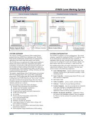
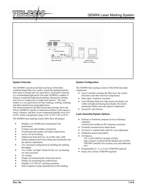
<strong>System</strong> Configuration<br />
The <strong>GEMINI</strong> basic package consists of the following major<br />
components.<br />
• <strong>Laser</strong> Controller (contains the fiber laser, the control<br />
electronics and other electrical components)<br />
• Fiber Optic/ Umbilical Assembly<br />
• <strong>Laser</strong> <strong>Marking</strong> Head (two high speed scan heads, two<br />
visible red light positioning laser diodes, the electromechanical<br />
shutter and some optical components)<br />
• <strong>System</strong> PC and software<br />
<strong>Laser</strong> Assembly <strong>System</strong> Options<br />
• Desktop or Notebook computer (in lieu of desktop<br />
computer)<br />
with powered cardbus-to-PCI expansion enclosure<br />
• Externally-mounted focus-finder diode<br />
• Tool post w/ manual hand crank for z-axis adjustment<br />
• Pushbutton station (start/abort)<br />
• I/O Options:<br />
TTL via PCI-DIO24 Card (Kit #53920)<br />
Opto-isolated via Merlin DCIO Module (Kit #53928)<br />
TMC090 Controller (for auxiliary axes and additional<br />
I/O)<br />
• Programmable X-, Y, or Z-axis (TMC090 required)<br />
• Rotary drive fixture (TMC090 required)<br />
Doc. No. 1 of 6
<strong>GEMINI</strong> General Specifications<br />
Compliance..........................CDRH and CUL<br />
Wavelength..........................1,060 nm (+/-10nm)<br />
<strong>Laser</strong> Type ...........................ytterbium doped Q-Switched fiber<br />
laser<br />
Q-Switch Frequency............20KHZ to 80KHz<br />
Average power per<br />
scan head (for Gemini 20FQ)…10 Watts (combined 20Watss)<br />
Average power per<br />
scan head (for Gemini 10FQ)…5 Watts (combined 10Watss)<br />
Beam quality ……………….M 2 < 2<br />
Long term power stability.....less than ± 5%<br />
Positioning...........................two red diodes<br />
Fiber optic cable length (for Gemini 20FQ)…3 meters (9.8 feet)<br />
Fiber optic cable length (for Gemini 10FQ)…5 meters (16.4 feet)<br />
Cooling:.................................Air cooled<br />
Max. Power Consumption(for Gemini 20FQ)….. less than 550W<br />
Max. Power Consumption(for Gemini 20FQ)….. less than 450W<br />
Operating Range....................10° to 35°C (50° to 95°F)<br />
Humidity................................10% to 85% non-condensing<br />
Expected MTBF ....................50,000 hours maintenance-free<br />
diode pumping source<br />
Shipping weight (for 160mm lenses ) ……..approx. 35 kg (77 lbs)<br />
<strong>Laser</strong> Controller<br />
The fiber laser is enclosed in the laser controller. The 3 meter (9.8<br />
feet) long fiber optic cable delivers the laser beam into the marking<br />
head.<br />
The laser controller also contains the laser and scan heads power<br />
supplies, driver control circuits, appropriate fusing, and a selectable<br />
115/230VAC, 50/60Hz power jack.<br />
<strong>GEMINI</strong> <strong>Laser</strong> <strong>Marking</strong> <strong>System</strong><br />
The controller’s front panel includes the system key switch, <strong>Laser</strong><br />
Off push button, manual safety shutter control, function indicators,<br />
and two displays. The displays allow monitoring the actual laser<br />
power and the working hours.<br />
This compact laser controller can be fitted to any standard-rack<br />
mount or it can be placed directly upon a desktop.<br />
<strong>GEMINI</strong> <strong>Laser</strong> Controller Console<br />
<strong>Laser</strong> Controller Specifications<br />
Dimensions (W x H x L) .......16.74” x 5.25” x 20.0”<br />
Weight...................................approx. 15.5 kg (34 lbs)<br />
Input Power (selectable) ........115/230VAC 50/60 Hz<br />
Doc. No. 2 of 6
Fiber Optic Beam Delivery Assembly<br />
The beam is delivered from the fiber laser source (in the laser<br />
controller) through a fiber optic cable to the marking head. One<br />
end of the fiber optic cable is permanently attached to the fiber<br />
laser source and cannot be removed. The standard fiber optic cable<br />
length is 3 meters (9.8 feet).<br />
Do not bend or kink the fiber optic cable during installation or<br />
maintenance. The fiber optic cable is stainless steel armored and<br />
will tolerate approximately 305 mm (12 in.) diameter long-term<br />
bend without damage.<br />
Under no circumstances should the fiber optic cable be<br />
disconnected or removed from the marking head. Disconnection or<br />
removal may in extreme cases, expose personnel to active laser<br />
energy and the optical components to outside contamination.<br />
(There is no an interlock which will prevent the laser source to<br />
deliver the laser beam via the fiber optic cable when the fiber optic<br />
cable is disconnected).<br />
<strong>Laser</strong> <strong>Marking</strong> Head Assembly<br />
The laser marking head includes two high speed scan heads, the<br />
sealed laser collimator, beam splitting and turning optical<br />
components, red positioning laser diodes, the electro-mechanical<br />
shutter .<br />
<strong>Laser</strong> <strong>Marking</strong> Head Specifications<br />
Dimensions (L x W x H) .............. 20.0” x 13.9” x 5.486”<br />
Mounting Weight (with 160mm lenses)<br />
...................................................... approx. 16 kg (35lbs)<br />
Mounting Holes ............................ six M5-0.8<br />
Visible Red Light Positioning <strong>Laser</strong> diodes<br />
The function of the red light positioning laser diodes is to provide<br />
a co-focal, visible red beams through the same optics that the main<br />
1,060 nm lasing beam travels. This provides a safe and convenient<br />
aid to the user for “one-off” part program setup. This visible red<br />
light maybe viewed on the work surface without the need for<br />
protective safety goggles. The visible red light positioning laser<br />
diodes are mounted within the laser marking head, positioned after<br />
the shutter. They can be viewed on the marking surface even if the<br />
shutter is in Closed position. Power to the red positioning lasers<br />
diodes are provided by a power supply in the laser controller via<br />
the umbilical cable assembly.<br />
<strong>GEMINI</strong> <strong>Laser</strong> <strong>Marking</strong> <strong>System</strong><br />
Galvanometer Optical Scanners<br />
Each scan head has two optic scanning galvanometers, one each<br />
for controlling X-axis beam positioning and Y-axis beam<br />
positioning. Galvanometer scanners are computer-controlled,<br />
high-performance, closed-loop, precision rotary motors. They<br />
consist of a motor section based on moving magnet technology<br />
and a high precision, closed-loop position detector. Attached to<br />
each motor shaft is an optically coated mirror assembly to deflect<br />
the beam. Each optically coated mirror assembly is factory<br />
balanced and bonded, then each combination of mirror and motor<br />
assembly are electronically equalized in the control circuitry.<br />
Galvanometer Optical Scanners<br />
Galvanometer (Scan Head) Specifications<br />
Repeatability………………………….
Flat Field Lens, Final Objective Lens, (F-Theta Lens)<br />
The final object lens is key to the marking performance of the<br />
system. This is the final coated optical lens that the beam will pass<br />
through before it strikes the marking target. The final objective<br />
lens is sometimes called the F-Theta Lens because the lens is<br />
optically corrected to provide an image height that is proportional<br />
to the scan angle (Theta), not the tangent of that angle, as is<br />
usually the case with traditional optical lenses. This lens is also<br />
called a flat field lens because when the beam is focused, the focus<br />
lies in a plane perpendicular to the optical axis of the lens. To<br />
protect the final objective lens from dust and debris, a clear<br />
protective cover is inserted between the work area and the lens.<br />
The lens and protective cover is held in place by an adapter ring<br />
called a bezel (mounting kit). The bezel fits directly into the<br />
machined galvo block. The lens and protective cover can be<br />
replaced in less than five minutes. A properly maintained lens will<br />
remain functional indefinitely. Periodically, as a standard practice,<br />
the lens should be cleaned using an approved optical lens cleaner<br />
and soft optical tissue.<br />
The following chart outlines the available lenses, their part<br />
numbers, the mounting kit (bezel) part numbers, and the resulting<br />
image field provided by the lens (in millimeters and inches).<br />
Lens<br />
Lens<br />
Part No.<br />
Mount. Kit<br />
Part No.<br />
<strong>Marking</strong> Field <strong>Marking</strong> Field<br />
Size (mm) Size (in)<br />
100 mm 42553 45 x 45 1.77 x 1.77<br />
160 mm 29942 90 x 90 3.54 x 3.54<br />
163 nm 42554 110 x 110 4.33 x 4.33<br />
254 mm 42555 155 x 155 6.10 x 6.10<br />
<strong>GEMINI</strong> <strong>Laser</strong> <strong>Marking</strong> <strong>System</strong><br />
<strong>Marking</strong> Characteristics<br />
Spot Size (line width). The laser marked spot size can be thought<br />
of as the line width of the image being marked. For all practical<br />
purposes, the laser-created text or machine-readable code can be<br />
programmed to mark or engrave smaller than can be seen without<br />
magnification. In the opposite extreme, it can be marked so large<br />
as to cover the entire marking field.<br />
In all cases, laser marked spot size is dependent on a variety of<br />
factors including lens selection, focus, laser power and the<br />
material being marked. The following chart is provided for<br />
reference only.<br />
Working clearance.<br />
Lens Spot Size (line width)<br />
100 mm 25 microns (.0010 in.)<br />
160 mm 40 microns (.0015 in.)<br />
163 mm 40 microns (.0015 in.)<br />
254 mm 60 microns (.0025 in.)<br />
Doc. No. 4 of 6<br />
Lens<br />
Working<br />
Clearance<br />
(mm) (in.)<br />
100 mm 97.0 3.82<br />
160 mm 176.0 6.93<br />
163 mm 185 7.28<br />
254 mm 296 11.65
<strong>System</strong> PC<br />
Gemini uses an off-the-shelf, IBM-compatible, desktop computer<br />
for running the Merlin ® II LS <strong>Laser</strong> <strong>Marking</strong> Software.<br />
The minimum computer requirements are as follows:<br />
• Pentium III with 128 Mb RAM<br />
• 17-in. SVGA Color Monitor<br />
• Multi-Gigabyte HDD<br />
• CD ROM Drive<br />
• 3.5-in. Floppy Disk Drive<br />
• Windows ® 2000 or Windows ® XP<br />
• Keyboard and Mouse<br />
• One RS-232 Port, Two USB Ports Serial Two PCI Slots<br />
Communications Protocol<br />
Two types of host interface are available (RS-232 or TCP/IP).<br />
Two protocols are available as well.<br />
Programmable Protocol is used where very simple one-way<br />
communications are required (such as with bar code scanners).<br />
Programmable Protocol provides no error checking or<br />
acknowledgment of transmitted data. Note that XON/XOFF<br />
Protocol applies even when Programmable Protocol is selected.<br />
The other type of interface is Extended Protocol. This protocol<br />
includes error checking and transmission acknowledgment. It<br />
should be used in applications where serial communication is a<br />
vital part of the marking operation.<br />
<strong>System</strong> Software<br />
<strong>Telesis</strong>’ powerful WIN32 Merlin ® II LS <strong>Laser</strong> <strong>Marking</strong> Software is<br />
a PC-based operating software package that comes standard with<br />
the ZENITH ® 10F <strong>Laser</strong> <strong>Marking</strong> <strong>System</strong>. It is a graphical user<br />
interface that makes marking pattern design quick and easy. The<br />
WYSIWYG (what-you-see-is-what-you-get) interface provides a<br />
to-scale image of the pattern as it is created. Just “click and drag”<br />
for immediate adjustment to field size, location, or orientation.<br />
The Merlin ® II LS includes tools to create and edit text (at any<br />
angle), arc text, rectangles, circles, ellipses, and lines. Multiple<br />
fields may be grouped and saved as a block to form a logo.<br />
Existing DXF CAD files can also be imported for marking. Nonprintable<br />
fields can be created to clearly display a graphical<br />
representation of the part being marked.<br />
For the second scan head in the Machine Properties, an extra<br />
Marker Setup tab is available to specify the X/Y offset, scan head<br />
orientation (Swap X/Y, Invert X, Invert Y) and calibration for the<br />
second head which is independent of the first scan head. This<br />
allows a marking part to be oriented differently under the second<br />
scan head. The individual calibration is necessary to calibrate the<br />
beam and aiming diode for the first and second scan heads.<br />
<strong>GEMINI</strong> <strong>Laser</strong> <strong>Marking</strong> <strong>System</strong><br />
Overview of Merlin-II LS User Interface<br />
Merlin ® II LS <strong>Laser</strong> <strong>Marking</strong> Software Specifications<br />
Operating <strong>System</strong> ..................Windows ® 2000 or Windows ® XP<br />
Desktop PC (Standard)<br />
Laptop (Optional)<br />
Font Generation.....................True Type Fonts<br />
Barcodes and Matrix .............2D Data Matrix, PDF417, BC 39,<br />
Interleaved 2 of 5, UPCA/UPCE BC<br />
128, Maxi Code, Code 93, QR Code<br />
and others<br />
Graphic Formats....................Raster and Vector: BMP, GIF, JPG,<br />
WMF, EMF, PLT, DXF<br />
Serialization...........................Automatic and Manual Input<br />
Host Interface Capable<br />
Linear <strong>Marking</strong>......................Scalable with Letter Spacing<br />
Control<br />
Arc Text <strong>Marking</strong>..................Scalable and Adjustable<br />
Drawing Tools.......................Line, Rectangle, Circle, Ellipse<br />
Doc. No. 5 of 6
<strong>System</strong> Setup<br />
Complete installation procedures are provided in the <strong>GEMINI</strong><br />
Installation/Maintenance Manual. The following procedures are<br />
listed for reference only to provide a general overview of the<br />
installation process.<br />
1. Equipment should remain powered down and in the OFF<br />
position until the mounting is complete.<br />
2. Place the computer, monitor, keyboard, and laser controller<br />
in the desired location. The standard fiber optic cable length<br />
is 3 meters (9.8 feet) long between the laser marking head<br />
assembly and the controller.<br />
3. Locate the laser marking head assembly on the selected<br />
mounting.<br />
a. Do not to bend or kink the fiber optic cable. The<br />
fiber optic cable will tolerate approximately 305 mm<br />
(12 in.) diameter bend without damage.<br />
b. Allow a minimum distance of 150 mm (6 in.) at the<br />
rear of the laser. This will provide sufficient room<br />
for a proper bend radius of the fiber optic cable.<br />
4. Mount the laser marking head assembly using any four of<br />
the six factory-tapped M5-0.8 mounting holes provided.<br />
a. Locate the six pre-drilled M5-0.8 mounting holes.<br />
Refer to the Mounting and Dimension Details drawing<br />
more information.<br />
b. <strong>Telesis</strong> recommends using a minimum of three (3)<br />
attach points for mounting the <strong>GEMINI</strong> laser.<br />
c. Mounting bolts must not extend into the marking<br />
head more than 7.6 mm (.3 in) to avoid interference<br />
with the internal components.<br />
5. Secure the laser to the mounting fixture using M5-0.8 bolts<br />
and lock washers. Do not over tighten bolts.<br />
6. Ensure the laser control console power switch (on the front<br />
panel) is OFF.<br />
7. Select the proper voltage setting (either 115V or 230V), and<br />
then connect the power cable.<br />
8. Refer to the <strong>GEMINI</strong> Operation Supplement for proper<br />
startup procedure of the complete system.<br />
9. Refer to the laser marking system Operation Manual for<br />
complete information on using the system software.<br />
<strong>GEMINI</strong> <strong>Laser</strong> <strong>Marking</strong> <strong>System</strong><br />
General Mounting Procedures<br />
If you chose to integrate the laser into a workstation that has not<br />
been designed by <strong>Telesis</strong>, you should keep in mind the following<br />
engineering considerations when integrating your system.<br />
• Design simple X-, Y-, and Z-axis adjustments.<br />
When designing a mounting fixture for the laser marking<br />
head, allow for simple three-axis adjustment to aid in<br />
horizontal, vertical, and lateral alignment of the laser marking<br />
head. Experience has shown that a minimum adjustment<br />
value of 12.7 mm (0.50 in.) is a prudent design consideration<br />
if the intent is to integrate the laser into workstation not<br />
designed by <strong>Telesis</strong>.<br />
• Ensure the part and the part holding fixture are<br />
perpendicular to the final objective lenses.<br />
When designing a work piece holding fixture, ensure the<br />
fixture is flat relative to the final objective lens of the galvo<br />
block assembly and square to the centerline of the laser<br />
marking field.<br />
• Ensure the part is stable and will not move during<br />
marking.<br />
<strong>Laser</strong> marking is a non-contact marking method. Typically all<br />
that is needed is simple fixturing pockets or X-axis, Y-axis<br />
datum rails.<br />
• Ensure the part width and length will fit in the<br />
marking area.<br />
Double check that all the parts to be marked will fit within<br />
the laser marking field. Ensure the marking area is not<br />
obstructed and can be targeted by the laser beam.<br />
• Ensure the combined total height of the part and<br />
fixturing does not exceed the working clearance of<br />
the final objective lens selected.<br />
Care should be taken to ensure that the laser beam can be<br />
focused on the part. The total combination of the part and<br />
fixturing height must not exceed the adjustment capability of<br />
the customer-supplied Z-axis. The working clearance is the<br />
distance between the bottom of the lens and the top of the part to<br />
be marked. See <strong>Marking</strong> Characteristics (<strong>Marking</strong> Field Size)<br />
for details on working clearances for the available lenses.<br />
Doc. No. 6 of 6