PCI Intellican - I+ME ACTIA GmbH
PCI Intellican - I+ME ACTIA GmbH
PCI Intellican - I+ME ACTIA GmbH

Create successful ePaper yourself
Turn your PDF publications into a flip-book with our unique Google optimized e-Paper software.
Content <strong>PCI</strong> IntelliCAN<br />
1 Introduction.......................................1-1<br />
1.1 Your <strong>I+ME</strong> <strong>PCI</strong>-IntelliCAN................................ 1-2<br />
1.2 System Requirements...................................... 1-3<br />
1.3 Delivery Contents............................................. 1-4<br />
1.4 Additional Products .......................................... 1-5<br />
1.5 Technical Specifications................................... 1-6<br />
2 Installation.........................................2-1<br />
2.1 Installation under Windows NT ........................ 2-2<br />
2.1.1 Install the hardware.............................................2-2<br />
2.1.2 Install the software driver ....................................2-2<br />
2.1.3 Install PcCANControl application ........................2-3<br />
2.1.4 Deinstalling under Windows NT ..........................2-3<br />
2.2 Installation under Win 9x.................................. 2-4<br />
2.2.1 Install software and plug in hardware..................2-4<br />
2.2.2 Install PcCANControl application ........................2-5<br />
2.3 Installation under Win 2000.............................. 2-6<br />
2.3.1 Install software and plug in hardware..................2-6<br />
2.3.2 Install PcCANControl application ........................2-9<br />
3 Hardware ...........................................3-1<br />
3.1 Functional description ...................................... 3-2<br />
3.1.1 Special memory areas ........................................3-2<br />
3.1.2 Flash memory areas ...........................................3-3<br />
3.2 Memory Mapping ............................................. 3-3<br />
3.3 Reset Control ................................................... 3-4<br />
3.4 CAN Controller ................................................. 3-4<br />
3.5 Serial Interfaces ............................................... 3-5<br />
3.6 <strong>PCI</strong> Interface .................................................... 3-5<br />
3.7 CAN Interface................................................... 3-6<br />
3.8 Physical Circuit Diagram .................................. 3-7<br />
3.8.1 Feature Connector ..............................................3-7<br />
3.9 Physical Layout ................................................ 3-8<br />
4 Techn. Support..................................4-1<br />
4.1 What to do if you have problems: .................... 4-2<br />
4.2 Solutions for all parts ....................................... 4-3<br />
4.3 Solutions for <strong>PCI</strong>-<strong>Intellican</strong>............................... 4-4<br />
5 Glossary.............................................4-1<br />
6 Literature ...........................................4-1
Content <strong>PCI</strong> IntelliCAN<br />
External documentation:<br />
A PcCANControl<br />
B LevelX API<br />
C LevelX Demos<br />
Administration of document<br />
General document version 1.11
Welcome to <strong>I+ME</strong> <strong>ACTIA</strong><br />
Before acquainting you with your new <strong>I+ME</strong> Hardware<br />
we would first like to thank you for purchasing our<br />
product. We are extremely pleased that you have<br />
chosen to place your trust in <strong>I+ME</strong> <strong>ACTIA</strong> and will do<br />
our best to satisfy whatever needs you may have. The<br />
following is a brief explanation highlighting our<br />
background, areas of expertise and general product<br />
lines. This products and the list of our world-wide<br />
branch offices show that you have found a competent<br />
partner in <strong>I+ME</strong> <strong>ACTIA</strong>.<br />
Since its foundation in 1986, <strong>I+ME</strong> <strong>ACTIA</strong> has made<br />
quite a name for itself. Our employees are dedicated to<br />
producing high-quality solutions in the field bus and<br />
multiplexed systems sectors. The knowledge of our<br />
experts allows to develop a spectrum of products which<br />
have been used in the automotive field as well as in<br />
general industrial environments. Our products can be<br />
used in all phases of system development: system<br />
definition, prototyping, evaluation and field application.<br />
Informatik und MikroElektronik
Whether your professional background is into industryprocess-control<br />
or development and test tools, we offer<br />
six product groups to fulfill your sophisticated needs.<br />
Tried and tested under the most severe conditions the<br />
automotive industry has to offer, our products have<br />
proved themselves again and again.<br />
Our six products groups are:<br />
1 CAN System Test & Design Tools<br />
Support of various user<br />
application phases: Learning,<br />
proto-typing, testing and<br />
evaluation of networked systems.<br />
Comfortable real-time simulation<br />
of message transfer<br />
characteristics in CAN networks.<br />
Tools for mobile diagnosis and tests.<br />
2 CAN PC Interfaces<br />
Easy interfacing between PCs, Laptops, notebooks and<br />
networks with automotive fieldbus – protocols. Available<br />
for all PC standard interfaces such as ISA, <strong>PCI</strong>,<br />
backplane, RS232, Centronics and PCMCIA.<br />
Development of applications under Windows according<br />
to real-time requirements is supported<br />
3 CAN Industrial I/O<br />
V 1.1<br />
1-2<br />
CAN-IO is an intelligent hardware<br />
concept for sensor / actuator interfacing.<br />
A modular architecture allows<br />
the flexible change target<br />
micro controllers for process<br />
control.
4 CAN System Application Software<br />
Enabling real-time system<br />
modeling, testing of networked<br />
systems as well as application<br />
support. Offering basic services<br />
for network communication which<br />
is applicable for various<br />
processors and programming<br />
languages. Facilitating the application interface for<br />
distributed industrial process control according to the<br />
CAL standard by CiA. Support of all Windows 32bit<br />
platforms.<br />
5 CAN System Know How<br />
6 Automotive Diagnostics<br />
Promoting the understanding of<br />
various network protocols in<br />
practice. Understanding of CAN<br />
networks with CAL in practice.<br />
Developing HW/SW solutions for<br />
customer specific problems. We<br />
offer CAN / CAL workshops and<br />
in-house seminars to enable CAN<br />
users to benefit from <strong>I+ME</strong><br />
<strong>ACTIA</strong>’s extensive knowledge.<br />
Assistance during the development<br />
phases. Diagnostic tools for quality<br />
control in production lines as well as<br />
after sales diagnostic, control and<br />
servicing tools are provided to<br />
manufacturers, suppliers and dealers<br />
of the car industry by <strong>I+ME</strong> <strong>ACTIA</strong>.<br />
V 1.1<br />
1-3
If you have any questions concerning our products or<br />
you look for specific solutions within our product groups,<br />
don’t hesitate to call us and benefit from <strong>I+ME</strong>’s<br />
extensive knowledge - your need is our desire.<br />
Our merger with the French corporation <strong>ACTIA</strong> in 1995<br />
allowed us to become a powerful supplier for the<br />
European automotive industry. <strong>ACTIA</strong> products include<br />
diagnostic systems for automotive service and<br />
maintenance as well as development and production of<br />
high quality on-board electronics. Joining forces with<br />
<strong>ACTIA</strong> has enabled <strong>I+ME</strong> to better service it’s<br />
international customers not only in Europe, but<br />
throughout the world.<br />
V 1.1<br />
1-4<br />
Headquarter:<br />
<strong>I+ME</strong> <strong>ACTIA</strong> <strong>GmbH</strong><br />
Rebenring 33<br />
38106 Braunschweig<br />
Germany<br />
T: +49 531 38701 0<br />
F: +49 531 38701 88<br />
WORLDWIDE REPRESENTATIVES
<strong>I+ME</strong> <strong>ACTIA</strong> Representatives<br />
SI-KWADRAAT <strong>ACTIA</strong> SA<br />
Nuenen, Netherlands Toulouse, France<br />
T: +31 40 2.631.185 T: +33 (0)5 61.17.61.61<br />
F: +31 40 2.838.092 F: +33 (0)5 61.55.42.31<br />
NOHAU ELEK. AB <strong>ACTIA</strong> INC. - ATI<br />
Malmö, Sweden Elkhart, Indiana USA<br />
T: +46 40 59.22.00 T: +1 (219) 293.75.05<br />
F: +46 40 59.22.29 F: +1 (219) 293.75.39<br />
If needed, please contact our associates below.<br />
ATAL SPOL SRO <strong>ACTIA</strong> DO BRASIL<br />
Tabor, Czech Rep. Porte Alegre, Brazil<br />
T: +420 361 251 791 T: +55 51 337.90.17<br />
F: +420 361 253 043 F: +55 51 337.60.81<br />
ATON SYSTEMS SA <strong>ACTIA</strong> de Mexico SA<br />
France Mexico<br />
T: +33 0 1.42.07.18.00 T: +525 119.22.78<br />
F: +33 0 1.42.07.85.55 F: +525 119.22.79<br />
VIDEOBUS Paher SA<br />
Getafe Madrid, Spain<br />
T: +34 91 665 26 26<br />
F: +34 91 665 23 24<br />
V 1.1<br />
1-5
Your <strong>I+ME</strong> <strong>PCI</strong>-IntelliCAN Overview,<br />
Systemrequirements, delivery contents and s.o.<br />
1 Introduction
Introduction<br />
Your <strong>I+ME</strong> <strong>PCI</strong>-IntelliCAN<br />
1.1 Your <strong>I+ME</strong> <strong>PCI</strong>-IntelliCAN<br />
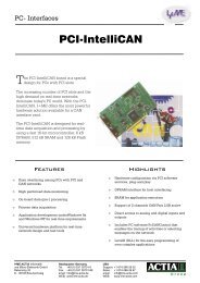
The <strong>PCI</strong>-IntelliCAN board is specially designed for PCs<br />
with <strong>PCI</strong> slots. Intended for real-time data acquisition<br />
and processing applications by using a fast 16-bit microcontroller.<br />
It allows a <strong>PCI</strong>-PC to easily interface with<br />
industirial and automotive CAN-networks. The<br />
IntelliCAN is a universal hardware platform for real-time<br />
network design and test tools and supported all<br />
Windows 32bit organisation systems.<br />
<strong>I+ME</strong> <strong>ACTIA</strong> is always eager to fulfill the needs of our<br />
customers. If problems should occur, please refer to<br />
troubleshooting. If the problem persists, then feel free to<br />
contact our after-sales-support using the following<br />
number:<br />
V 1.1<br />
1-2<br />
After-sales service<br />
<strong>I+ME</strong> <strong>ACTIA</strong> <strong>GmbH</strong><br />
Rebenring 33<br />
D-38106 Braunschweig<br />
Germany<br />
Tel: ++ 49 (0) 531 38 701 38<br />
Fax: ++ 49 (0) 531 38 701 88<br />
e-mail: info@ime-actia.de
1.2 System Requirements<br />
Introduction<br />
System Requirements<br />
Your system must need the following minimum<br />
requirements:<br />
• Pentium 133 MHz processor or higher<br />
• <strong>PCI</strong> Slot<br />
• Windows 9x, NT4.0, ME, 2000<br />
<strong>I+ME</strong> <strong>ACTIA</strong> is always dedicated to developing<br />
solutions for our customers problems, and if you have<br />
any questions about compatibility with other software or<br />
hardware combinations, then please contact our<br />
marketing department at the following number:<br />
Marketing and Sales<br />
<strong>I+ME</strong> <strong>ACTIA</strong> <strong>GmbH</strong><br />
Rebenring 33<br />
D-38106 Braunschweig<br />
Germany<br />
Tel: ++ 49 (531) 38 701 28<br />
Fax: ++ 49 (531) 38 701 88<br />
e-mail: info@ime-actia.de<br />
V 1.1<br />
1-3
Introduction<br />
Delivery Contents<br />
1.3 Delivery Contents<br />
Your <strong>PCI</strong>-IntelliCAN Duo Channel delivery package<br />
includes:<br />
• 1 x <strong>PCI</strong> Board<br />
• 1 x <strong>I+ME</strong> Product CD-Rom:<br />
• Users Manual (as pdf file)<br />
• LevelX Manual (as pdf file)<br />
• PcCANControl Manual (as pdf file)<br />
• Drivers for Windows 9x, WinNT4.0, Win 2000<br />
• PC-Application for Windows<br />
• Sample code for programming under LevelX<br />
V 1.1<br />
1-4
1.4 Additional Products<br />
Introduction<br />
Additional Products<br />
In addition to the delivery contents, it is possible to order<br />
more products that enhance the functionality of your<br />
<strong>PCI</strong>-IntelliCAN. The following components and options<br />
can be purchased through any <strong>I+ME</strong> affiliated distributor<br />
(see Welcome to <strong>I+ME</strong> <strong>ACTIA</strong>) or from <strong>I+ME</strong> directly<br />
• Chip setup software<br />
• Various physical interfaces<br />
• Galvanic decoupling<br />
For new products and developments please call:<br />
Marketing and Sales<br />
<strong>I+ME</strong> <strong>ACTIA</strong> <strong>GmbH</strong><br />
Rebenring 33<br />
D-38106 Braunschweig<br />
Germany<br />
Tel: ++ 49 (531) 38 701 28<br />
Fax: ++ 49 (531) 38 701 88<br />
e-mail: info@ime-actia.de<br />
V 1.1<br />
1-5
Introduction<br />
Technical Specifications<br />
1.5 Technical Specifications<br />
Dimensions 108mm x 155mm<br />
PC Addresses Via <strong>PCI</strong><br />
PC Interrupts Via <strong>PCI</strong><br />
Processor SAB C165<br />
Oscillator Frequency On-board Crystal 20 MHz<br />
(CAN @ 16 MHz)<br />
On-Board Memory 8 kB DPRAM (16Bit)<br />
512 kB SRAM (16Bit) (opt. 1 MB)<br />
128 kB Flash ( 8Bit) (opt. 512 kB)<br />
Physical Interface CAN: ISO 11898<br />
CAN Interface 9 pin SubMinD for CAN I<br />
(CiA/DS 102 male)<br />
9 pin SubMinD for CAN II<br />
(CiA/DS 102 male)<br />
Galvanic Decoupling Optional for both CAN channels<br />
Temperature Range 0° .. +70°C<br />
Socket for I/O 4 x analog inputs<br />
4 x digital input or output<br />
2 x UART /<br />
1 x serial port sync. /<br />
1 x serial port async.<br />
direct link to micro-controller<br />
V 1.1<br />
1-6
Your <strong>I+ME</strong> <strong>PCI</strong>-IntelliCAN installation.<br />
Hardware and software installation are described.<br />
2 Installation
Installation<br />
Installation under Windows NT<br />
2.1 Installation under Windows NT<br />
2.1.1 Install the hardware<br />
First you have to take care about the right installation of<br />
the <strong>PCI</strong>-IntelliCAN hardware in your PC. Please follow<br />
also the instructions of your PC hardware supplier.<br />
Before opening your PC make sure that the PC is<br />
disconnected from your powersupply.<br />
You have to plugin the <strong>PCI</strong>-IntelliCAN board into a free<br />
<strong>PCI</strong> slot. After plugin your <strong>PCI</strong>-IntelliCAN hardware is<br />
ready for operation.<br />
Close your PC and turn power on. The next step is to<br />
install the software.<br />
2.1.2 Install the software driver<br />
1 Insert the CD. The setup programm will start<br />
automatically, if not please start the program<br />
“START.EXE” in root path.<br />
2 Go to "Software Installation"<br />
3 Choose your operating system, is important.<br />
4 Choose your hardware component at the selection<br />
box then press "Start Installation". If the file is started<br />
(*.com file), follow the steps on the screen. If<br />
necessay type in the password.<br />
5 If password is correct software will be installed<br />
successful.<br />
V 1.1<br />
2-2
Installation<br />
Installation under Windows NT<br />
2.1.3 Install PcCANControl application<br />
1 Insert the CD. The setup programm will start<br />
automatically, if not please start the program<br />
“START.EXE” in root path.<br />
2 Go to "Software Installation"<br />
3 Choose your operating system, is important.<br />
4 Choose PcCANControl component at the selection<br />
box then press "Start Installation". If the file is started<br />
(*.com file), follow the steps on the screen. If<br />
necessay type in the password.<br />
5 Start "PcCANControl", select “create a new project”<br />
and then the hardware, at this case<br />
“<strong>PCI</strong>-<strong>Intellican</strong>2#0” or<br />
“<strong>PCI</strong>-<strong>Intellican</strong>2#1”<br />
After the selection the necessary software is<br />
activated on your PC. For further information see<br />
also separate manual about PcCANControl.<br />
2.1.4 Deinstalling under Windows NT<br />
Remember if the software should be deinstalled, please<br />
use normal Windows deinstallation service. You found it<br />
under...<br />
START/SETTINGS/CONTROLPANEL/ADD/REMOVE PROGRAM<br />
(START/EINSTELLUNGEN/SYSTEMSTEUERUNG/SOFTWARE)<br />
V 1.1<br />
2-3
Installation<br />
Installation under Win 9x<br />
2.2 Installation under Win 9x<br />
At Windows 9x the installation procedure is a little<br />
extravagant.<br />
IMPORTANT:<br />
First you have to install the software.<br />
Second you must plug&play the hardware (restart incl.)<br />
2.2.1 Install software and plug in hardware<br />
1. Insert the CD. The setup program will start<br />
automatically, if not please start the program<br />
“START.EXE” in root path.<br />
2. Go to "Software Installation"<br />
3. Choose your operating system, is important.<br />
4. Choose your hardware component at the selection<br />
box then press "Start Installation". If the file is<br />
started (*.com file), follow the steps on the screen. If<br />
necessay type in the password. This application<br />
only copy all necessary files to the hard disk, no<br />
installation of driver is done at this time. Please<br />
follow the requests (e.g. password) of the<br />
installation program.<br />
5. Turn off the PC and plug in the <strong>PCI</strong>-IntelliCAN<br />
card. Before opening your PC make sure that the<br />
PC is disconnected from your powersupply.<br />
6. Start your PC again. Windows 9x detect the new<br />
hardware and ask you about the new driver. Please<br />
choose the driver on your harddisk. You found it<br />
under<br />
C:\ime_LX\LX9Xpi2j\... (default)<br />
V 1.1<br />
2-4
Installation<br />
Installation under Win 9x<br />
All necessary files you found under these directory.<br />
Follow the instructions on screen.<br />
7. Reboot the system again to start up the new driver.<br />
8. If the system is started again the installation is<br />
finished.<br />
2.2.2 Install PcCANControl application<br />
1. Insert the CD. The setup programm will start<br />
automatically, if not please start the program<br />
“START.EXE” in root path.<br />
2. Go to "Software Installation"<br />
3. Choose your operating system, is important.<br />
4. Choose PcCANControl component at the selection<br />
box then press "Start Installation". If the file is<br />
started (*.com file), follow the steps on the screen. If<br />
necessay type in the password.<br />
5. Start "PcCANControl", select “create a new project”<br />
and then the hardware, at this case<br />
“<strong>PCI</strong>-<strong>Intellican</strong>2#0” or<br />
“<strong>PCI</strong>-<strong>Intellican</strong>2#1”<br />
After the selection the necessary software is<br />
activated on your PC. For further information see<br />
also separate manual about PcCANControl.<br />
V 1.1<br />
2-5
Installation<br />
Installation under Win 2000<br />
2.3 Installation under Win 2000<br />
At Windows 2000 the installation procedure is a little<br />
extravagant.<br />
IMPORTANT:<br />
First you have to install the software.<br />
Second you must plug&play the hardware (restart incl.)<br />
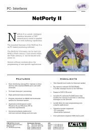
2.3.1 Install software and plug in hardware<br />
1. Insert the CD. The setup program will start<br />
automatically, if not please start the program<br />
“START.EXE” in root path.<br />
2. Go to "Software Installation"<br />
V 1.1<br />
2-6<br />
Software installation
Installation<br />
Installation under Win 2000<br />
3. Choose your operating system, is important.<br />
4. Choose your hardware component at the selection<br />
box then press "Start Installation". If the file is<br />
started (*.com file), follow the steps on the screen. If<br />
necessay type in the password. This application<br />
only copy all necessary files to the hard disk, no<br />
installation of driver is done at this time. Please<br />
follow the requests (e.g. password) of the<br />
installation program.<br />
5. Turn off the PC and plug in the <strong>PCI</strong>-IntelliCAN<br />
card. Before opening your PC make sure that the<br />
PC is disconnected from your powersupply.<br />
1<br />
2<br />
3<br />
V 1.1<br />
2-7
Installation<br />
Installation under Win 2000<br />
6. Start your PC again. Windows 2000 detect the new<br />
V 1.1<br />
2-8<br />
hardware and ask you about the new driver. Please<br />
choose the driver on your harddisk. You found it<br />
under C:\ime_LX\LXN5pi2j\... (default).
Installation<br />
Installation under Win 2000<br />
All necessary files you found under these directory.<br />
Follow the instructions on screen.<br />
7. Reboot the system again to start up the new driver.<br />
8. If the system is started again the installation is<br />
finished.<br />
2.3.2 Install PcCANControl application<br />
1. Insert the CD. The setup programm will start<br />
automatically, if not please start the program<br />
“START.EXE” in root path.<br />
2. Go to "Software Installation"<br />
3. Choose your operating system, is important.<br />
4. Choose PcCANControl component at the selection<br />
box then press "Start Installation". If the file is<br />
started (*.com file), follow the steps on the screen. If<br />
necessay type in the password.<br />
5. Start "PcCANControl", select “create a new project”<br />
and then the hardware, at this case<br />
“<strong>PCI</strong>-<strong>Intellican</strong>2#0” or<br />
“<strong>PCI</strong>-<strong>Intellican</strong>2#1”<br />
After the selection the necessary software is<br />
activated on your PC. For further information see<br />
also separate manual about PcCANControl.<br />
V 1.1<br />
2-9
The components which make up your <strong>PCI</strong>-IntelliCAN<br />
and the way they work together for CAN access.<br />
3 Hardware
Hardware<br />
Functional description<br />
3.1 Functional description<br />
The <strong>I+ME</strong> <strong>PCI</strong>-IntelliCAN is equipped with the 16-bit<br />
SAB C165 microcontroller. The controller’s clock<br />
frequency is 20 MHz.<br />
The <strong>PCI</strong>-IntelliCAN is equipped with 512 kB of SRAM.<br />
The SRAM is selected by the micro-controller’s CS 1<br />
and driven in 16-bit non-multiplexed mode.<br />
3.1.1 Special memory areas<br />
In addition to the SRAM, the <strong>PCI</strong>-IntelliCAN contains a<br />
8 KB Dual Port RAM (DPRAM), used for data exchange<br />
between the SAB C165’s core and the PC. The DPRAM<br />
is selected by CS 0 and driven in 16-bit non-multiplexed<br />
mode. To avoid collisions during the access of the<br />
DPRAM, the bus cycles are delayed by the DPRAM’s<br />
ready signal.<br />
The DPRAM can be used for interrupt signals in the<br />
following ways:<br />
V 1.1<br />
3-2<br />
• A PC write access to the address 1FFEh of<br />
the DPRAM can be used to cause an<br />
interrupt at the C165’s P2.15 line.<br />
• The C165 write access to the address<br />
1FFCh of the DPRAM causes an interrupt at<br />
the <strong>PCI</strong> chip. A reset of these interrupts is<br />
caused by a read access to the DPRAM<br />
addresses from the opposite sides.
3.1.2 Flash memory areas<br />
Hardware<br />
Memory Mapping<br />
In addition to the SRAM and the DPRAM, the <strong>PCI</strong>-<br />
IntelliCAN contains a 128 kB Flash for storage of<br />
firmware or user specific programs. The memory is<br />
selected by the microcontroller’s CS 2 and driven in 16bit<br />
non-multiplexed mode.<br />
3.2 Memory Mapping<br />
The mapping of the <strong>PCI</strong>-IntelliCAN memory<br />
components is user-defined and has a wide range of<br />
possible addresses. DPRAM is mapped in the PC<br />
address range. The mapping of the DPRAM, CAN<br />
controller, and SRAM in the SAB C165 address space<br />
are all configurable. The mapping of the <strong>PCI</strong>-<br />
IntelliCAN’s memory (DPRAM and reset logic) in the PC<br />
address range is controlled through the <strong>PCI</strong> host<br />
adapter.<br />
The mapping of the memory components and the CAN<br />
in the SAB C165 address area is controlled through the<br />
SAB C165 external bus interface. For more information<br />
about the functionality of the SAB C165 external bus<br />
interface, see literature list at the end of this manual.<br />
V 1.1<br />
3-3
Hardware<br />
Reset Control<br />
3.3 Reset Control<br />
The reset of the SAB C165 is controlled through a port<br />
of the <strong>PCI</strong> chip that can be set or reset by the PC-SW<br />
with IO accesses to the <strong>PCI</strong> chip.<br />
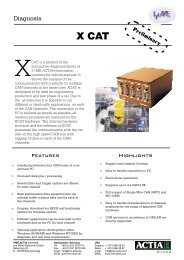
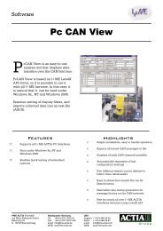
3.4 CAN Controller<br />
The <strong>PCI</strong>-IntelliCAN also includes two CAN controller<br />
SJA1000.<br />
The first CAN chip is controlled via the CS 3 line and<br />
A14 addressline of the SAB C165 and driven in 16-bit<br />
multiplexed mode. The first CAN controller’s interrupt<br />
output signal is connected to the SAB C165’s P2.8 line.<br />
The second CAN chip is controlled via the CS 3 line and<br />
A14 addressline of the SAB C165 and driven in 16-bit<br />
multiplexed mode. The second CAN controller’s<br />
interrupt output signal is connected to the SAB C165’s<br />
P2.9 line.<br />
Adresses : CAN1 = CS3 + BASE<br />
CAN2 = CS3 + BASE + 0x4000<br />
V 1.1<br />
3-4<br />
16bit<br />
CAN 1<br />
SJA1000<br />
C165<br />
2.8 CS3 A14<br />
2.9<br />
INTR<br />
16V8<br />
CS CS<br />
16bit<br />
INTR<br />
CAN 2<br />
SJA1000
3.5 Serial Interfaces<br />
Asynchronous Serial Interface<br />
Hardware<br />
Serial Interfaces<br />
The RxD and TxD lines of the internal SAB C165 UART<br />
are connected to the <strong>PCI</strong>-IntelliCAN feature connector<br />
and can be used for customer specific applications. For<br />
more information about the SAB C165 asynchronous<br />
serial interface, see literature list at the end of this<br />
manual.<br />
Synchronous Serial Interface<br />
The SCLK 1 , MRST 2 and MTSR 3 lines of the internal<br />
SAB C165 serial synchronous interface are connected<br />
to the feature connector and can be used for the<br />
connection to external devices. For more information<br />
about the SAB C165 synchronous serial interface, see<br />
literature list at the end of this manual.<br />
3.6 <strong>PCI</strong> Interface<br />
The <strong>PCI</strong>-IntelliCAN uses a <strong>PCI</strong> standard interface<br />
(Release 2.1). The <strong>PCI</strong>-IntelliCAN has 256 bytes of<br />
attribute memory containing information for the <strong>PCI</strong> chip<br />
information. After the configuration of the <strong>PCI</strong>-<br />
IntelliCAN’s software driver, the following resources are<br />
available :<br />
• 1 x 16 kB block at the memory range<br />
• 1 x IRQ<br />
1 SCLK: Serial Clock<br />
2 MRST: Master Receive Slave Transmit<br />
3 MTSR: Master Transmit Slave Receive<br />
V 1.1<br />
3-5
Hardware<br />
CAN Interface<br />
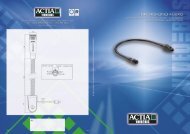
3.7 CAN Interface<br />
The physical interface of the <strong>PCI</strong> IntelliCAN consists of<br />
two transceivers. They are linked on two 9-pin<br />
sub-min-D male connectors. (CAN1 and CAN2)<br />
Both physical interfaces are standard ISO11898<br />
physical interfaces. The picture below shows the<br />
pinning of these connectors.<br />
Pin 1, 4, and 8 are not connected on the <strong>PCI</strong>-board.<br />
Pin 5 is also GND<br />
Pin 9 is use for external hw and n.c. at <strong>PCI</strong>-board !<br />
V 1.1<br />
3-6
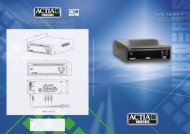
3.8 Physical Circuit Diagram<br />
Hardware<br />
Physical Circuit Diagram<br />
The following picture (see 3.9) shows the circuit<br />
diagram of the physical interface. It is possible to adapt<br />
user specific physical interfaces via <strong>I+ME</strong>’s Transceiver<br />
Baby Boards (TxBB).<br />
3.8.1 Feature Connector<br />
The Feature connector of the <strong>PCI</strong> IntelliCAN board is<br />
used to adapt additional signal to the PC IntelliCAN.<br />
Signal name Pin Pin Signal name<br />
GND 1 2 SCLK<br />
GND 3 4 MTSB<br />
GND 5 6 MBSI<br />
Vcc 7 8 Vcc<br />
Vcc 9 10 Vcc<br />
GND 11 12 TxD_O<br />
GND 13 14 RxD_D<br />
GND 15 16 I/O_8<br />
I/O_0 17 18 I/O_1<br />
I/O_2 19 20 I/O_3<br />
I/O_4 21 22 I/O_5<br />
I/O_6 23 24 I/O_7<br />
AVcc 25 26 AGND<br />
AIN_0 27 28 AIN_1<br />
AIN_2 29 30 AIN_3<br />
AIN_4 31 32 AIN_5<br />
AIN_6 33 34 AIN_7<br />
V 1.1<br />
3-7
Hardware<br />
Physical Layout<br />
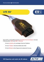
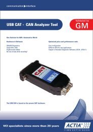
3.9 Physical Layout<br />
V 1.1<br />
3-8<br />
1<br />
Featurconnector<br />
TxBB<br />
CAN1<br />
RAM 512K Flash<br />
RAM 512K<br />
TxBB<br />
SJA1000<br />
SJA1000<br />
CAN2<br />
TxBB TxBB<br />
CAN1 CAN2<br />
first second<br />
CAN Hardwareconnect: CAN1 CAN2<br />
CAN Softwareconnect CAN0 CAN1<br />
C165 DPRAM<br />
<strong>PCI</strong><br />
9052
Common problems and how to solve them. How to get<br />
in touch with our after-sales support experts if you so<br />
desire.<br />
4 Techn. Support
Techn. Support<br />
What to do if you have problems:<br />
4.1 What to do if you have problems:<br />
First and foremost, please read Installation very closely<br />
and make sure that you performed your installation<br />
exactly as described.<br />
For developers:<br />
The Key is often used in developing environments in<br />
combination with the API and/or DLL. If the<br />
PcCANControl software is functioning properly, then<br />
there is no problem with general CAN access. You<br />
should check your usage of the API of DLL.<br />
If the PcCANControl software is not functioning, please<br />
consult the list of common problems below and their<br />
possible solutions.<br />
If you encounter difficulties which are not discussed in<br />
the manual, or if you need more help than is offered in<br />
Installation and Troubleshooting, please call our<br />
after-sales service. Our experts will do their best to<br />
solve whatever problem you might have.<br />
V 1.1<br />
4-2
4.2 Solutions for all parts ...<br />
Techn. Support<br />
Solutions for all parts ...<br />
General problem to install and run the hardware:<br />
Under NT: Check if the carddriver is started under<br />
the device manager. Status “started”<br />
Under 9x: Check if the card is correct listed under<br />
the device manager, no yellow spot on it.<br />
The system crashes after choose the hardware at<br />
PcCANControl:<br />
The selected memory area is not free, or the<br />
selected interrupt is being used by another<br />
application. Make sure that no conflicts exist on<br />
your system. If you get a blue screen under Win<br />
NT it is most likely that a memory or IRQ conflict<br />
is occur.<br />
PcCANControl launches correctly, but CAN access<br />
is not possible:<br />
A) Check the transceiver cable and CAN<br />
connectors, are all connectors are correctly<br />
plugged in?<br />
B) If the sub-min-D connectors at the end of the<br />
cables are hot, remove the Key and call <strong>I+ME</strong>.<br />
C) If you use higher baudrates (< 100kBaud),<br />
remember to protect the end of line with<br />
resistors [120 Ohm]<br />
D) It is possible that the CAN line driver is defect,<br />
after you have a short curcuit or high current on<br />
bus.<br />
V 1.1<br />
4-3
Techn. Support<br />
Solutions for <strong>PCI</strong>-<strong>Intellican</strong><br />
4.3 Solutions for <strong>PCI</strong>-<strong>Intellican</strong><br />
Problems under Windows 2000:<br />
The SW installation is successful and the card is<br />
inserted correct but no commuication is possible<br />
• Try to plug in the card into an other <strong>PCI</strong> port.<br />
The SW installation is successful and the card is<br />
detect correct but no commuication is possible<br />
General problems with ACPI exist, one of the next<br />
cases can help.<br />
• Use the latest SP from Windows 2000.<br />
• Disable the “Assign IRQ for USB” (similar Text<br />
possible) in BIOS. The BIOS map this IRQ to a<br />
common IRQ, the IRQ for USB is set by Windows<br />
2000 special, so the funktion of USB has no<br />
restrictions. Note: These case is not possible by all<br />
PC’s.<br />
• Force a Window 2000 conform mapping by blocking<br />
the <strong>PCI</strong>-plug&play mechanism into the BIOS<br />
settings: Set under “PNP/ISA Configuration” the<br />
“Resource controlled by manual” funktion, after this<br />
set all but one IRQ’s to “Legacy ISA”.<br />
Tips to last point:<br />
Check the IRQ under Windows 2000 device<br />
manager. Choose “view” and then “Recource to<br />
connections”. There is a list of all IRQ’s of<br />
<strong>PCI</strong>/ISA devices. All <strong>PCI</strong>-devices should be set to<br />
one IRQ (by activ ACPI !). You should choose the<br />
V 1.1<br />
4-4
Techn. Support<br />
Solutions for <strong>PCI</strong>-<strong>Intellican</strong><br />
IRQ with the most entries in list. Use these IRQ to<br />
set him into the BIOS to <strong>PCI</strong>/ISA PNP.<br />
• Disable of the ACPI interface.<br />
Note:<br />
Depends on BIOS type (AMI, AWARD, Compaq,..)<br />
Depends on ServicePack you use.<br />
General:<br />
If you will disable the ACPI mechanism you must<br />
first disable it under Windows 2000 and then<br />
disable it into BIOS. If not, Windows 2000 will never<br />
restart correct.<br />
If you have install the SP1 from Win2000 this BIOS<br />
settings are not necessary.<br />
For more infos please contact our<br />
After Sales Service.<br />
In this mode our <strong>PCI</strong>-card works, if the IRQ is<br />
shared or not.<br />
V 1.1<br />
4-5
1 Glossary
Glossary<br />
Solutions for <strong>PCI</strong>-<strong>Intellican</strong><br />
Glossary<br />
ACPI<br />
Advanced Configuration and<br />
Power Interface.<br />
Managing the Powersystem<br />
of you computer. New since<br />
Windows 2000.<br />
CAN<br />
Controller Area Network<br />
Fieldbus network system<br />
useful in EMV critical<br />
environment<br />
-BCAN<br />
Basic-CAN<br />
The used chip has only a<br />
small buffer structure. All filter<br />
has to be defined in software<br />
and have to managed by the<br />
application.<br />
-ECAN<br />
Extended-CAN<br />
The used chip supports<br />
extended identifiers<br />
( CAN 2.0B / 29bit IDs)<br />
-FCAN<br />
Full-CAN<br />
The used chip has an internal<br />
buffer structure with mailbox<br />
architecture and supports<br />
Remote Frames.<br />
-SCAN<br />
Standard-CAN<br />
The used chip supports<br />
standard identifiers<br />
( CAN 2.0A / 11bit IDs)<br />
BIOS<br />
Basic Input Output System<br />
An abbreviation for Basic<br />
Input / Output System. A set<br />
V 1.1<br />
4-2<br />
of instructions/routines stored<br />
in ROM. These routines work<br />
closely with hardware devices<br />
(memory chips, disk drives<br />
and monitor) to input and<br />
output interrupt requests<br />
indicating when a device is<br />
ready to accept or send data.<br />
DPRAM<br />
Dual Ported Random Access<br />
Memory.<br />
The data for communication<br />
between PC and CANhardware<br />
are exchange via a<br />
DPRAM.<br />
I/O<br />
An abbreviation for lnput<br />
Output. Refers to the sending<br />
(input) and receiving (output)<br />
of data through an 110<br />
channel in the CPU. Example:<br />
The keyboard inputs data to<br />
the 110 channel in the CPU<br />
that in turn is output to the<br />
monitor.<br />
IRQ<br />
An abbreviation for Interrupt<br />
Request. A signal sent by a<br />
device and routed through the<br />
BIOS indicating when a<br />
device is ready to accept or<br />
send data.<br />
PCMCIA<br />
Personal Computer Memory<br />
Card International<br />
Association. A trade<br />
association of leading<br />
hardware and software<br />
vendors, established to adopt<br />
a set of standards pertaining<br />
to adapter slots and PC cards<br />
for portable PC accessories.
Slot / Socket<br />
A receptacle on a micro,<br />
portable, laptop or palmtop<br />
computer that is used to<br />
insert and operate PCMCIA<br />
PC Cards. Also referred to as<br />
a Socket.<br />
Socket-Controller<br />
A PC system hardware<br />
component that manages the<br />
operation of PCMCIA sockets<br />
in conjunction with system<br />
software.<br />
Upper-Memory<br />
Memory area within the PC<br />
address space between 640<br />
KB and 1 MB. This area is<br />
used by hardware devices<br />
like graphics controller. The<br />
DPRAM of the CANcard is<br />
located in the Upper Memory.<br />
Glossary<br />
Solutions for <strong>PCI</strong>-<strong>Intellican</strong><br />
V 1.1<br />
4-3
For more information's ...<br />
2 Literature
Literature<br />
[1] PCCANControl User manual<br />
<strong>I+ME</strong> Actia documentation (available on WEB)<br />
[2] LevelX User Manual<br />
<strong>I+ME</strong> Actia documentation (available on WEB)<br />
[3] CAN - Controller Area Network<br />
Grundlagen und Praxis<br />
Hüthig <strong>GmbH</strong>, Heidelberg<br />
ISBN 3-7785-2263-7<br />
[4] SAB 80C167CR User Manual<br />
Siemens AG<br />
[5] SAB C167CR Description of the On-chip CAN-<br />
Module<br />
Siemens AG<br />
[6] CiA<br />
DS 102-1CAN in Automation e.V<br />
www.can-cia.com<br />
V 1.1<br />
4-2