EPP Europe P2.2019

Create successful ePaper yourself
Turn your PDF publications into a flip-book with our unique Google optimized e-Paper software.
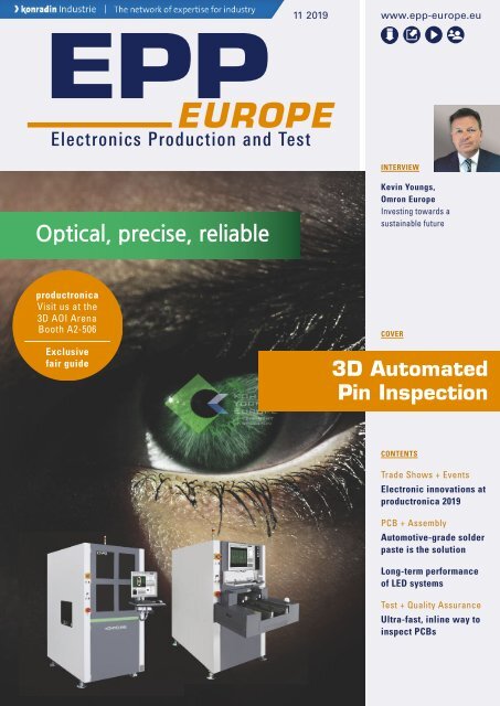
11 2019 www.epp-europe.eu<br />
INTERVIEW<br />
<br />
Kevin Youngs,<br />
Omron <strong>Europe</strong><br />
Investing towards a<br />
sustainable future<br />
productronica<br />
Visit us at the<br />
3D AOI Arena<br />
Booth A2-506<br />
Exclusive<br />
fair guide<br />
COVER<br />
3D Automated<br />
Pin Inspection<br />
CONTENTS<br />
Trade Shows + Events<br />
Electronic innovations at<br />
productronica 2019<br />
PCB + Assembly<br />
Automotive-grade solder<br />
paste is the solution<br />
Long-term performance<br />
of LED systems<br />
Test + Quality Assurance<br />
Ultra-fast, inline way to<br />
inspect PCBs
EDITORIAL<br />
productronica 2019<br />
The electronics development and production tradeshow, productronica, will<br />
take place on November 12–15, 2019 at Messe München. International exhibitors<br />
and visitors will come together to see all the highlights this show<br />
has to offer. This includes, special events and forums, discussions, workshops,<br />
and more. Semicon Europa and InPrint Munich will also take place<br />
parallel to the show. Pick up your productronica Guide, to make your trip<br />
even easier.<br />
Visit us at the 3D AOI Arena, Booth A2-506.<br />
GLOBAL.<br />
AHEAD.<br />
SUSTAINABLE.<br />
Inspecting press-fit technology<br />
The Title story depicts the many different methods that are available for<br />
press-fit inspection. As miniaturization, complexity, and futuristic trends are<br />
becoming more prominent, some methods can be more effective than<br />
others. A 3D AOI pin inspection solution is key to ensure accurate, high<br />
quality production. In combination with Moiré technology and smart software,<br />
it will accurately locate and measure the pin body, right from the start.<br />
Growing importance for accurate inspection.<br />
All about automation<br />
A Slovakian electronics manufacturing company wanted to automate their<br />
production line on a bigger scale. They needed a solution that combined<br />
high quality production with high productivity and flexibility, all together<br />
with full customer support. After careful consideration, two soldering machines<br />
and a customized stencil printer with an integrated 3D SPI function<br />
was chosen. As production needs increased, a reflow soldering solution<br />
and a full tunnel wave soldering system were acquired.<br />
Demand for top quality.<br />
Automatizing reverse engineering<br />
Repairing printing circuit boards can be challenging as well as expensive, especially<br />
after long lifecycles where CAD data might not be available. Reverse<br />
engineering is a process that can be used to repair, copy, clone, test, and<br />
redesign a PCB module. This process contains five steps which can be automized<br />
with a flying probe system. Combined with specific software tools and<br />
mechanical abilities, a flying prober can create a comprehensive test program<br />
where a full data package can be generated.<br />
Flexibility of flying probers.<br />
YOUR<br />
PRODUCTION.<br />
DRIVEN BY<br />
KURTZ ERSA.<br />
At the Productronica show in Munich, Ersa<br />
will be presenting future-proof solutions for<br />
electronics production and its focus topics<br />
electromobility, autonomous vehicles,<br />
5G applications and Industry 4.0.<br />
Visit the Ersa experts on site and take the<br />
opportunity to exchange ideas on how you<br />
can make your electronics production even<br />
more efficient. Also through automation<br />
solutions from a single source.<br />
SEE YOU AT KURTZ ERSA IN HALL A4!<br />
Source: Carina Zarfelder<br />
Charlene Hesse<br />
Online Editor <strong>EPP</strong> E<br />
12 - 15 NOVEMBER<br />
www.driven-by-kurtzersa.com
Content 11 2019<br />
<strong>Europe</strong>an Magazine for<br />
Production and Test in the<br />
Electronics Industry<br />
Cover<br />
3D automated pin inspection<br />
Source: Messe München/ Thomas Koy<br />
Source: MicroCare Corporation<br />
18<br />
Covering all the latest innovations, productronica 2019 will<br />
gather the entire industry, all in one place.<br />
66<br />
An electronics cleaning solutions manufacturer<br />
discusses three ways to clean PCBAs.<br />
During final assembly, press-fit technology has many advantages.<br />
Some prefer this method to soldering due to its reliability, however,<br />
it does come with defect manufacturing challenges. Due to ever<br />
increasing board and component complexity, most traditional inspection<br />
techniques are not fit to ensure accurate inspection.<br />
Combining the KY-P3 pin inspection solution with Moiré technology<br />
and the KSMART software will accurately locate and measure the<br />
pin body, right from the start.<br />
Pinning down defects to improve entire process<br />
News + Highlights<br />
6 Highly efficient automation lines<br />
Demand for IPTE’s production equipment<br />
10 Investing towards a sustainable future<br />
Interview with Omron‘s <strong>Europe</strong>an Sales Manager<br />
16 Strong focus on soldering and sintering<br />
Pink establishes development department<br />
16 Joining the UN Global Compact<br />
Advantest commits to a sustainable future<br />
16 Advancing in future developments<br />
Viscom forms New Technologies team<br />
16 Business development manager<br />
Essemtec appoints department head<br />
16 Regional manager for US and Canada<br />
Kyzen grows Western markets<br />
Trade Shows + Events<br />
18 Comprehensive international tradeshow<br />
Accelerating innovation at productronica 2019<br />
20 Solutions for assemblies and systems<br />
SMTconnect 2019: Meeting manufacturing challenges<br />
25 Compare. Evaluate. Decide.<br />
Accurate inspection at the 3D AOI Arena<br />
Source: Saki <strong>Europe</strong><br />
109<br />
Using bottom-side AOI for assembly processes<br />
increases productivity, while reducing substrate<br />
damage.<br />
PCB + Assembly Features<br />
60 Cleaning electronic PCBs<br />
Traceabillity and process assurance (Zestron)<br />
62 Selective soldering of challenging components<br />
Ensuring process control (Nordson Select)<br />
65 Product-Updates PCB + Assembly<br />
66 Decreasing PCBA malfunction<br />
Cleaning for PCB reliability (MicroCare)<br />
70 Pushing for high quality production<br />
All about automation (Ersa)<br />
73 Automobile industry driving for advanced packaging<br />
Electrification, ADAS, and connectivity (ASM)<br />
4 <strong>EPP</strong> EUROPE November 2019
Source: Koh Young<br />
54<br />
DEFECTS<br />
ELIMINATED<br />
RELIABILITY<br />
DELIVERED<br />
76 Product-Updates PCB + Assembly<br />
78 Long-term performance and reliability of LEDs<br />
Utilizing protection materials (Electrolube)<br />
82 Electrical reliability in harsh conditions<br />
Automotive-grade solder paste (Indium)<br />
85 Product-Updates PCB + Assembly<br />
86 Rotary soldering table with four stations<br />
Tinning coil connections (Zevatron)<br />
88 Process technology ready for future trends<br />
Systematic convection soldering (Rehm)<br />
93 Product-Updates PCB + Assembly<br />
94 Soldering method using laser technology<br />
Local non-contact heating (Koki)<br />
98 Balance of equipment and process control<br />
Conformal coating line (Nordson Asymtek)<br />
102 Product-Updates PCB + Assembly<br />
Test + Quality Assurance Features<br />
104 Resistance welder for quality assurance<br />
Safety in mobile energy production (Hilpert)<br />
106 Reverse engineering with flying probe<br />
Automated process for full data (Seica)<br />
109 Ultra-fast, inline way for PCB inspection<br />
2D-bottom side AOI system (Saki)<br />
112 Product-Updates Test + Quality Assurance<br />
Columns<br />
3 Editorial<br />
4 Contents<br />
114 Imprint/List of advertisers<br />
AVOID:<br />
VOIDING<br />
AVOID:<br />
DENDRITIC GROWTH<br />
AVOID:<br />
SOLDER BEADING<br />
AVOID:<br />
HEAD-IN-PILLOW<br />
AVOID:<br />
NON-WET OPENS<br />
AVOID:<br />
INSUFFICIENT<br />
SOLDER DEPOSITS<br />
Visit us at Productronica:<br />
Hall A4, Booth 214<br />
Learn more:<br />
www.indium.com/avoidthevoid/<strong>EPP</strong>E<br />
Contact our engineers:<br />
askus@indium.com<br />
©2019 Indium Corporation<br />
<strong>EPP</strong> EUROPE November 2019 5
NEWS + HIGHLIGHTS<br />
High level demand for production equipment<br />
From depanelizing to highly<br />
efficient automation lines<br />
Panel cutter, router, depaneler – whatever the machines that separate the individual board assemblies<br />
that are manufactured in differently sized panels are called- they are a central stage<br />
in electronics manufacturing environments. For over 20 years now, IPTE, headquartered in<br />
Belgium, has been successful in this industry with its families of routers, as well as, automation<br />
solutions for the electronics and machinery industries.<br />
Sales Director Rainer Krohmann and Dr. Jörg Handke, Business<br />
Unit Manager Systems, from the company’s German office in<br />
Heroldsberg, discuss the success and benefits of the systems.<br />
“Our market position has become clear by the matter of fact that<br />
customers often come to us with demand for an efficient depaneling<br />
machine. And then as further discussions and questions on application,<br />
handling, functionality and automation reveal, they are<br />
going to order a comprehensive automation solution, including the<br />
router, for their electronics production, because our highly flexible<br />
and efficient range of equipment has convinced them.”<br />
Solutions with flexibility<br />
It is important, as the managers make clear, that as a supplier of<br />
such system solutions, the company has always actively and cooperatively<br />
taken up the requirements of the market and then, on a<br />
case-by-case basis, implemented promptly the relevant options requested.<br />
In this case, they are also a competent partner for users<br />
resolving such projects. After all, these system solutions have to exhibit<br />
their performance in daily operation. “The feedback from our<br />
customers in the field, with whom we generally maintain long-term<br />
and trustful relationships, including the exchange of special knowhow,<br />
is very important for such further developments,“ emphasizes<br />
Rainer Krohmann. This also applies to upcoming manufacturing con-<br />
Modular machine concepts enable a wide range of applications<br />
IPTE offers a total of four different depaneling machine families in its<br />
portfolio.<br />
The systems EasyRouter and TopRouter for off-line operation originate<br />
from the headquarters in Genk, Belgium. On the other hand, FlexRouter II<br />
and SpeedRouter in-line machines are developed and manufactured in<br />
Heroldsberg, Germany. Continuous improvements have made these systems<br />
very efficient. For more than 20 years, the in-line capable and flexible<br />
SpeedRouter for the depaneling processes sawing and milling or a<br />
combination of these has been continuously further improved. Designed<br />
for high-speed requirements, it is characterized by high reliability, robustness<br />
and speed. The modular concept allows for a variety of different<br />
tools, grippers and in-feed and out-feed transport mechanisms for in-line<br />
and off-line applications. Integration in manufacturing lines is supported<br />
by a wide range of different cells and modules. The system is also ideally<br />
suited for requirements demanding very narrow tolerance limits and short<br />
cycle times.<br />
The FlexRouter II has been developed for medium to high production<br />
throughput with a high product mix. It now also works with framelessrouting<br />
technology. Despite the small space requirement of only onemeter<br />
width, panels up to 330 mm x 500 mm can be processed. Four of the<br />
seven axes are designed as linear drives. The panel is loaded, clamped<br />
and measured in position by means of a width-adjustable belt conveyor. A<br />
freely programmable servo gripper on a Cartesian 3-axis system with rotary<br />
axis holds the panel during the cutting process, thus basically eliminating<br />
PCB-specific tooling costs. The milling spindle under the PCB is also<br />
positioned with a Cartesian 3-axis system and can be equipped with different<br />
spindle types to realize even complex applications without difficulties.<br />
The automated change of gripper fingers allows simple and fast<br />
product changes. Various options are available for positioning and moving<br />
the panels: such as belt conveyor (also double beam), tray magazines up<br />
to a size of 600 x 400 mm, work-piece holder, linear shuttle and turntable.<br />
As an option, it is possible to check the singularized board assemblies by<br />
means of optical inspection. Separation programs can be created with<br />
camera support or with the integrated DXF converter for the transfer of<br />
CAD data. The machine is intuitive and easy to operate. Features, such as<br />
the use of several milling cutter sections for cost reduction, automatic<br />
milling bit change and detection of bit breakage, are standard.<br />
The EasyRouter II is a low-cost off-line depaneler for operations from the<br />
top of the panel at a speed of up to 60 mm/sec. Among other features,<br />
the accuracy, user guidance and noise level have been optimized. The<br />
complete process sequence of the milling tool can be displayed in 3D<br />
real-time positions or simulated using industry-specific parameters to determine<br />
the cycle time from the original product data. Loading and unloading<br />
take place alternately during the cutting process via a turntable<br />
with an integrated work-piece carrier. Handling is carried out manually,<br />
and robot support (Cobot) can also be implemented. X and Y axes of the<br />
milling machine feature fast and precise spindle drives. Automatic<br />
change of the milling tool with bit recognition and diameter inspection<br />
are also provided for. The bit position can be learned to use a camera;<br />
ESD monitoring of the milling tool is possible. Programming can be provided<br />
via DXF files or codes.<br />
6 <strong>EPP</strong> EUROPE November 2019
Dr. Jörg Handke and Rainer Krohmann (from left) during a tour at the manufacturing<br />
floor of the IPTE in-line depaneler machines: “The demand for our solutions<br />
is particularly high.”<br />
Source: IPTE<br />
Dr. Handke: “Frameless routing allows a further increase in efficiency and<br />
cost reduction, as panel waste is significantly reduced.“<br />
Source: IPTE<br />
cepts, such as Industry 4.0/Smart Factory and their implementation.<br />
In addition, there are user requests for easy program generation<br />
and CAD import of product data, high flexibility and functions, such<br />
as the optimization of the edge-cut procedure, detailed system<br />
monitoring and ergonomics, as well as application-specific customization<br />
and user aids. As Dr. Handke states, “operation, programming<br />
and maintenance must be practically intuitive and self-explaining.<br />
Straightforward and machine-aided troubleshooting, as well as<br />
preventive maintenance and statistical process control (SPC), are inherited<br />
elements of our machine concept. Of course, also a reduction<br />
of downtime is very important, because shutdowns in lines are<br />
always very costly. The system also includes so-called software wizards<br />
for providing user assistance. It is not exaggerated to say that<br />
our software has now become a unique selling point in the equipment<br />
design.“<br />
Transparent cost and quality situation<br />
“To set up a cutting process, the operator has to only follow the<br />
carving process on the panel with the aid of the machine. The result,<br />
including possible optimization, is thus immediately available. The<br />
transfer of CAD data to a cutting program is likewise convenient.<br />
Because the trend towards smaller boards is increasing, panels<br />
with 256 single assemblies are already a reality in production, high<br />
precision and cutting speed are essential. Also, we have further optimized<br />
the management of dust generation and extraction as well<br />
as the reduction of operating noise. And, of course, the exact monitoring<br />
of tool wear or tool breakage as well as statistical evaluation<br />
and traceability are included in the performance machine package.<br />
And for production monitoring, users can extract the data from the<br />
running process and prepare it immediately,“ Dr. Handke further explains.<br />
Therefore, not only the costs for the separation of a single<br />
board assembly are transparent for the user, but also the quality of<br />
process and product.<br />
No wonder that besides the outstanding hardware design, the company<br />
also gives high priority to software development. Rainer Krohmann<br />
underlines the current development in this topic of interest in<br />
the industry and its impact on the company: “For some time now,<br />
we have been hiring an above-average number of employees in the<br />
software area, in order to meet the increasing demands in the application,<br />
optional enhancement, functionality and user-friendliness.<br />
The software‘s proportion of added value in our machines is thus<br />
constantly increasing.“<br />
Frameless routing increases efficiency and profitability<br />
As well as on the hardware side, highly innovative solutions continue<br />
to be developed. As Dr. Handke, responsible for the design of<br />
the SpeedRouter and FlexRouter II product families, points out:<br />
“With the new frameless routing (option), we are now increasing<br />
the efficiency of the FlexRouter II. Because with frameless routing,<br />
i.e. without the use of frames, there are only very few circuit board<br />
leftovers.“ This is also interesting from both, an ecological and a<br />
cost-related point-of-view, because it reduces the amount of nonrecyclable<br />
material and therefore reduces the amount of waste that<br />
has to be disposed of. This solution also features a transport mechanism<br />
without any edges, which enables fast, stress-free and pre-<br />
<strong>EPP</strong> EUROPE November 2019 7
NEWS + HIGHLIGHTS<br />
cise separation by milling. Further enhancements in the cutting process<br />
are the outstanding board cut quality, in which no torque<br />
(force) is applied to the part singularized, whereby the grippers work<br />
without any distortion and with absolute positioning accuracy.<br />
“With the extensive range of different<br />
equipment options in our four<br />
depanelizer families, we can meet<br />
virtually any customer requirement”,<br />
notes Dr. Handke.<br />
A system was developed according to customer specifications in<br />
which the panels are processed via 12 motorized axes, and additional<br />
processes are also integrated into the depaneler machine. In<br />
addition to the relevant cutting options, such as sawing, milling or<br />
laser operations as well as various application-specific gripper<br />
mechanisms, the integration of in-line cells for handling, transport,<br />
stacking and barcode reading or writing, is also part of feasible system<br />
configurations. Furthermore, optionally available are optical process<br />
monitoring as well as the measurement and control of the singularized<br />
boards by automatic vision system (AOI). The outstanding<br />
performance of the equipment used is, of course, decisive for<br />
meeting the requirements of the customers with high precision,<br />
speed, availability and economy. “It goes almost without saying, the<br />
implementation of all relevant industry standards and interfaces for<br />
automation in electronics manufacturing is an essential task for us,“<br />
adds Sales Director Krohmann.<br />
Close-up of a depanelizer with built-in verification of components and some<br />
more options: those are complex and extremely reliable systems, too.<br />
Source: IPTE<br />
High-speed and precision<br />
For IPTE as a supplier, this means that the range of solutions extends<br />
from various in-line systems for the large volume to small<br />
series production, each of which can be specifically configured according<br />
to application requirements. The high efficiency can also be<br />
seen, for example, with maximum cutting speeds of up to 60 mm/s,<br />
resulting in short processing times of approx. 1 to 1½ seconds per<br />
board. Line cycle times in the region of 7 seconds can, therefore, be<br />
realized without complications, depending on the user‘s requirements.<br />
In addition, there are very small positioning tolerances of the<br />
axes (repeatability) in the order of ± 1–2 μm and, as Dr. Handke explains,<br />
„with this specification we have clearly a leading position in<br />
the depaneler industry. A further decisive factor of economic efficiency<br />
is also the fast retooling and high user-friendliness of the machines,<br />
as well as the very small footprint required on production<br />
floors. In general, space is very limited here and therefore also a<br />
cost factor that should not be underestimated.“<br />
The technology of the company’s equipment can also be seen in<br />
other relevant characteristics. The automation specialist also implements<br />
additional work cells into the integrated line, such as oddform<br />
assembly, electrical and/or electromechanical testing back-end<br />
tasks, etc., right through to the packaging of the finished product.<br />
Users can thus put together turnkey production configurations that<br />
are individually tailored to their specific requirements. Irrespective<br />
of whether the product mix consists of small and medium-sized<br />
production batches or very large volumes of practically identical<br />
boards, the configurations can be matched precisely to the production<br />
volumes and individual automation concepts. Dr. Handke comments:<br />
“Of course, a system solution must be exactly tailored to<br />
the task and the customer‘s requirements. Parameters, such as cutting<br />
speed and cycle time, are just as important as the quality of the<br />
cut-out edges of the material, the efficiency of the dust extraction or<br />
the required space on the production floor.“<br />
And as Rainer Krohmann adds: “As a general contractor for a complete<br />
production line, our customers can take it for granted that<br />
IPTE is fully in charge of adhering to the performance parameters of<br />
such system solutions and of the smooth integration and operation<br />
of the individual modules and processing stations. The advantage<br />
for the customer is quite obvious: there is always only one contact<br />
for whatever issue may turn up, namely, just us“. As both, Business<br />
Unit Manager Systems Dr. Handke, and Sales Director Krohmann,<br />
conclude commonly: “It is essential, in addition to flawless, efficient<br />
and safer processes and procedures, that we offer our customers<br />
optimal and trouble-free operation of their plants and systems with<br />
an explicitly increased added value.“ The current position on the market,<br />
which the managers describe in unison positively, shows that<br />
the company‘s machine concept turned out a grand success: “The<br />
demand for our depaneling systems continues to be high. Since<br />
2016, we have been able to increase sales significantly by more<br />
than 100 %, and even this year and next year, we can also expect excellent<br />
figures of plus 50 %.“ (Gerhard B. Wolski)<br />
productronica, Booth A1-534<br />
www.ipte.com<br />
8 <strong>EPP</strong> EUROPE November 2019
Momentum II Printers<br />
A proven, highly-productive<br />
printer platform now with a set<br />
of new exciting technologies.<br />
NEW<br />
Patented<br />
selective soldering<br />
technology that<br />
excels at meeting<br />
the challenges of<br />
miniaturization.<br />
Meet with ZEVAm+<br />
technical experts and<br />
engineers at<br />
Productronica<br />
Together in Process Perfection<br />
ITW EAE brings together the world-leading brands of electronics assembly equipment. The combined<br />
knowledge and experience of the ITW EAE group is driving the development of next generation<br />
technology like the ZEVAm+ Selective Soldering System and the MPM Momentum II Printer line. We<br />
are committed to high-quality products backed by application and process expertise. We will help<br />
optimize your equipment for maximum performance and improved productivity and yield.<br />
Come see all our latest developments at Productronica Booth A4 554<br />
Learn more at www.itweae.com<br />
A division of Illinois Tools Works<br />
<strong>EPP</strong> EUROPE November 2019 9
NEWS + HIGHLIGHTS<br />
INTERVIEW<br />
Investing towards a sustainable future<br />
Industry 4.0 and automation have been on-going trends that have<br />
become more attainable and accessible. The future of the electronics<br />
manufacturing industry lies on companies that are willing to<br />
invest in the progress of technology. In an interview with Kevin<br />
Youngs, the <strong>Europe</strong>an Sales Manager of Omron <strong>Europe</strong>’s Automated<br />
Inspection Systems Division, he discusses trends and<br />
goals the company is striving towards, to reach their vision of<br />
the future for all industries, including industrial automation,<br />
electronic component, and more. Following their mission of being<br />
a pioneer in creating inspired solutions for the future, the company<br />
is not only focused on futuristic trends, such as flexible manufacturing,<br />
AI, and digital factory, but also to continue to cover all aspects<br />
of the production line, including smart vision inspection.<br />
INFO<br />
Integrated automation<br />
All Omron sensing and control products are designed with integration<br />
in mind. As each physical component is controlled by the Sysmac<br />
automation platform and is designed to be interoperable with any<br />
other Omron component, integration into any production environment<br />
is made simple. This platform provides a single software development<br />
environment to ease application development. Standard form factors<br />
and protocols also facilitate the upgrade and maintenance of the line.<br />
Intelligent automation<br />
The IIoT relies on the collection and organisation of large amounts of<br />
data from the factory floor to ensure that the line is always operating<br />
at maximum efficiency. The company’s intelligent machines incorporate<br />
sophisticated machine learning techniques, to make the correct<br />
decisions close to where they are needed on the line. The company’s<br />
controllers also feature an integrated SQL database to simplify communication<br />
between the factory floor and the IT layer to allow data<br />
and control commands to flow freely in both directions.<br />
Interactive automation<br />
The IIoT production environment needs both the cognitive skills and<br />
flexibility of humans and strength, accuracy and data capability of robots<br />
to work together to achieve manufacturing excellence. Creating a<br />
safe working environment is essential to allow both humans and robots<br />
to work together. A new generation of collaborative robots have<br />
been introduced that allow humans and robots to work in close proximity<br />
to each other.<br />
In an interview with Kevin Youngs, he discusses the company’s actions and<br />
investments towards the future of technology as well as their environmental<br />
targets.<br />
How much does Omron invest in research and<br />
development and how many people are employed in<br />
this area?<br />
Research and development expense is an important long-term investment<br />
for the Omron Group. We have set a standard for R&D expense<br />
at 7 % of sales, and we intend to raise this level to 7.5 % by<br />
fiscal 2020. Our target for investments in core technologies, including<br />
AI and robotics, is about 1 % of sales. Dedicating capital to the<br />
progress of technology represents up-front investments that will<br />
bear fruit for corporate growth 10 and 20 years down the line. This is<br />
the type of investment we must undertake as a manufacturing company,<br />
if we are to develop innovations that improve lives and contribute<br />
to a better society. Accordingly, we will continue to make<br />
bold investment decisions that challenge the frontiers of science,<br />
balancing discipline and risk to deliver to the world innovation.<br />
What is the significance of the innovative<br />
automation concept?<br />
Manufacturers face many challenges when moving towards an agile<br />
and flexible production environment. It is only when they are confident<br />
of meeting both the demands set by consumers and the markets<br />
that they can begin the journey to truly flexible manufacturing<br />
and the ultimate goal of the digital factory. Omron’s complete range<br />
of hardware and software products have been designed from the<br />
ground up to assist that process by providing the highest levels of<br />
integration, highly advanced intelligence capabilities and safe and<br />
easy interaction with the complex technology.<br />
Source: Omron <strong>Europe</strong><br />
10 <strong>EPP</strong> EUROPE November 2019
Thrives on a Challenge. Loves Variety.<br />
The ultimate multi-process inspector for<br />
paramount speed, accuracy and ease of use.<br />
AOI<br />
SPI<br />
CMM<br />
SQ3000 All-in-One Solution<br />
Loaded with Powerful Tools that cover Inspection<br />
and Measurement for AOI, SPI and CMM.<br />
Fast and highly accurate, repeatable and reproducible measurements for metrology<br />
applications in the manufacturing of a wide variety of products such as PCBs, semiconductors<br />
and consumer electronics.<br />
The SQ3000 offers unmatched accuracy with the revolutionary Multi-Reflection Suppression<br />
(MRS) technology by meticulously identifying and rejecting reflections caused by shiny<br />
components. Effective suppression of multiple reflections is critical for accurate measurement,<br />
making MRS an ideal technology solution for a wide range of applications including those with<br />
very high quality requirements.<br />
www.cyberoptics.com<br />
Copyright © 2019. CyberOptics Corporation, Inc. All rights reserved.<br />
Visit us at<br />
Productronica Germany<br />
Hall A2 - Booth 439<br />
See the SQ3000 at the<br />
3D-AOI Arena<br />
Hall A2 - Booth 506<br />
<strong>EPP</strong> EUROPE November 2019 11
NEWS + HIGHLIGHTS<br />
INTERVIEW<br />
Source: Omron <strong>Europe</strong><br />
To assist manufacturers, the company has launched its innovativeautomation<br />
(i-Automation) programme, which is intended to provide<br />
manufacturers with a consistent, reliable way of ensuring they can<br />
meet both consumer demands and the changing needs of industry.<br />
i-Automation is based on three ‘i’s – integrated, intelligent and interactive.<br />
Together these three pillars can be combined to provide<br />
manufacturers with the highest levels of quality, sustainability and<br />
operational excellence that will help meet any future demands.<br />
The innovative-automation philosophy is the shortest and quickest<br />
route for manufacturers to surpass customer expectations and<br />
achieve manufacturing excellence.<br />
Constantly growing demands on component production<br />
require preventive, integrated strategies<br />
for zero-defect production. What do they look like<br />
at Omron?<br />
For many years now, the company has used a process template for<br />
back-casting to create innovation driven by social needs. We contribute<br />
to a better society by developing technologies and products<br />
necessary to achieve near-future design, incubating businesses that<br />
become an indispensable part of society.<br />
100 % reliability and achieving zero defect processes are essential<br />
for example in electric vehicle and advanced driver assistance systems<br />
(ADAS). Therefore, electronic assemblies of automotive PCB<br />
processes must meet the highest quality manufacturing standards.<br />
To meet these customer needs in PCB optical and X-ray inspection<br />
in the SMT process, the company’s solutions guarantee the quality<br />
of PCB components and the strength of solder joints. Automatic full<br />
inspection offers extremely high inspection accuracy and eliminates<br />
defective products and any inspection variations caused by manual<br />
work. We provide manufactures with user-friendly in-line inspection<br />
machines that can be easily implemented in the manufacturing line,<br />
offering reliable and robust performance.<br />
For zero-defect, the Q-up system collects and monitors data,<br />
all while making improvements based on information from<br />
the inspection system.<br />
Zero defect production means avoiding the causes<br />
of deviation even before the service has been completed.<br />
How and what is Omron doing to approach<br />
zero-defect production?<br />
The new Artificial Intelligence solution, which is now available, collects,<br />
analyzes and utilizes data on ‘edge’ devices within a controller<br />
to prolong equipment longevity and detects unforeseen abnormalities<br />
to prevent failures. It is the first AI machine automation controller<br />
with a Sysmac library, and fuses control functions of manufacturing<br />
lines and equipment with AI processing at manufacturing<br />
sites in real time.<br />
The process of collecting raw data from machines is completely<br />
automated by the new AI controller, which operates on the “edge”<br />
within the machine, ensuring higher data fidelity and consistency. In<br />
addition, the controller automatically creates data models from correlation<br />
analysis and monitors machine status based on that model.<br />
The hardware is based on the Sysmac NY5 IPC and the NX7 CPU<br />
and includes the AI Application Components. This is a library of preprogrammed<br />
predictive maintenance function blocks, based on the<br />
know-how that the company has gathered from typical applications.<br />
How do you deal with and handle the immense<br />
amounts of data?<br />
Taking the example of the AI Controller, as it does not require a<br />
huge amount of data on unusual incidents, it is easier and faster to<br />
implement than other solutions. While cloud-based AI solutions<br />
place enormous demands on infrastructure and IT, and the processing<br />
of data volumes is a tedious and time-consuming undertaking,<br />
machine-level AI is ideal for predictive maintenance and machine<br />
control. It combines line control functions with real-time AI-based<br />
data processing. The advantage is that they can reliably identify and<br />
quickly respond to unforeseen situations in real time, improve<br />
quality, maintenance and machine lifecycles, and scale as needed.<br />
Sensors that collect the required information directly at the machine<br />
12 <strong>EPP</strong> EUROPE November 2019
enable deeper and more up-to-date data analysis. In addition, the<br />
consolidation and compression of really necessary information is<br />
possible, further optimizing oversight and transparency.<br />
It is not always easy to reach high-quality zero-defect<br />
production with low quantity with frequent<br />
product changes or a high mix of complex products.<br />
How does the company help with this?<br />
Omron systems cover all parts of the production line, including<br />
quality inspection. Whether providing a complete system solution or<br />
a partial upgrade to an existing system, each component is geared<br />
towards ensuring the highest quality control. For inspection and<br />
quality control, the visual inspection units monitor production in real<br />
time and respond instantly to any defect.<br />
Data sent from the vision system is processed locally and sent via<br />
the cloud for powerful analysis that allow the system to take appropriate<br />
actions. The system is totally interlinked, with the improved<br />
connection between machines in a manufacturing line, delivering<br />
more accurate quality control and higher efficiency. If any error is<br />
detected, the system compensate automatically, allowing production<br />
to continue unaffected. The smart automation solutions are fast<br />
and possess lots of processing power, yet they are easy to use. This<br />
combination of speed, intelligence and user-friendliness delivers the<br />
most effective inspection and transparent quality control.<br />
Line set-ups can be changed quickly for new production runs, and<br />
the recognition pattern for quality inspection can be updated easily<br />
in the software. This ensures that different variants or even different<br />
products are produced and packaged correctly. The system is also<br />
future-proofed as it can be easily adapted to accommodate any<br />
changes to regulations. Therefore, manufacturers do not need to<br />
worry about what they might need to do to their production lines to<br />
meet future regulations. All that is required is to rollout a new firmware<br />
update for the existing solution.<br />
How strongly does the human factor manipulate a<br />
test result?<br />
Being able to catch a defective product before they are shipped to<br />
customers can bring significant savings in both time and money,<br />
preventing expensive product recalls, wasted production and potentially<br />
expensive legal costs.<br />
As an example, for perishable products, from food to pharmaceuticals,<br />
quality inspection of the packaging is also critical. An unreadable<br />
barcode or an incorrect expiry date could result in perfectly<br />
good products being discarded. And increasingly strict legislation is<br />
making clear marking a top priority for all types of product.<br />
As production lines become ever more automated, inspection and<br />
quality control also need to be more automated. Automated systems<br />
can improve a line’s effectiveness, by performing tasks quickly<br />
and accurately. The real benefits only truly materialize when ‘smart’<br />
automation is implemented, utilizing such features as smart data.<br />
When this is applied to vision inspection systems, defects can be<br />
spotted and dealt with swiftly with minimal impact to the line. A<br />
smart vision inspection system can make any production line efficient<br />
and less wasteful, both in terms of produce and down time.<br />
TEST PROBES<br />
ARE HIGH-<br />
PRECISION<br />
PRODUCTS<br />
» For top quality<br />
standards<br />
» For a wide range<br />
of applications<br />
» Custom-made designs<br />
We combine precision,<br />
innovation and reliability<br />
for your benefit.<br />
VISIT US AT THE<br />
PRODUCTRONICA<br />
TRADE FAIR IN MUNICH<br />
FROM NOVEMBER<br />
12 – 15, 2019!<br />
Hall A1, booth 558<br />
PTR HARTMANN GmbH<br />
Gewerbehof 38<br />
59368 Werne (Germany)<br />
www.ptr-hartmann.com<br />
<strong>EPP</strong> EUROPE November 2019 13
NEWS + HIGHLIGHTS<br />
INTERVIEW<br />
Is there preventive quality assurance?<br />
Many pre and post SMT processes still utilize sample inspection by<br />
operators, the challenge is to achieve full inspection automatically in<br />
the production line to reach “zero defect”.<br />
For example, and along with the progress in the development of<br />
automotive technology, such as ADAS (Advanced Driver-Assistance<br />
System), self-driving, and EVs (Electric Vehicles), the installation<br />
rates of important electrical safety components have been increasing,<br />
such as millimeter-wave radar to detect vehicles and pedestrians<br />
with wireless connection, the electronic mirror that is<br />
mounted as replacement of the current sideview mirror and inside<br />
rearview mirror, and LED headlamps. These high-density and miniaturized<br />
automobile electric components require time to conduct visual<br />
inspection. Therefore, their current inspection process is the<br />
sampling inspection in each unit.<br />
As an example, Omron VT-M121 enables the detection of defects,<br />
which is similar to or more precise than the human eye, by using the<br />
sophisticated image-processing system, „FH series“ with the illumination<br />
pattern of the MDMC Light that can flexibly change the<br />
illumination color and the angle. Thanks to „NJ damping control“<br />
that integrates the sequence control and motion control, it can also<br />
minimize the camera vibration, therefore, realize high-speed and<br />
high-accuracy inspection. By simultaneous dimension and visual inspection,<br />
the machine has reduced the inspection time and improved<br />
the dimension and inspection performance with high repeat<br />
accuracy. Our new system contributes to the safety and reliability of<br />
automobile manufacturing by achieving customers‘ „zero defect“<br />
through full-scale guarantee and accumulation and management of<br />
inspection data in place of on-the-spot inspections within and<br />
beyond the SMT process.<br />
Can a complete automation of the test processes<br />
ensure the repeatability of the process chain?<br />
The company supports “manufacturing without defect”. Along with<br />
changes of trends within our world, „manufacturing“ has also<br />
undergone a major change with significantly increased quality level<br />
requirement. To support the principle of 4Ms „Man (worker)“, „Machine<br />
(facility)“, „Material (raw materials)“, and „Method (work<br />
method)“ and to continue manufacturing high-quality products, the<br />
company proposes a Q-up system that performs linking of data<br />
from facilities, collection and monitoring of the data, as well as making<br />
improvements, based on the quality information of inspection<br />
system. This allows real-time capturing of „changes that affect<br />
quality“ of 4Ms in production fluctuations and assisting efficient improvement<br />
activities.<br />
What does Omron do to protect the environment?<br />
Our energy management domain advances the adoption of renewable<br />
energy to reduce CO2 emissions and build a society in which<br />
people live in comfort. We work with our partners to promote the<br />
use of power conditioners and storage battery systems for the<br />
benefit of a clean environment. The Environmental Solutions Business<br />
and Field Engineering Co., Ltd. are the two entities through<br />
which we conduct most of our environmental business.<br />
We believe that building an environment for a sustainable society is<br />
part of improving lives and contributing to a better society, as stated<br />
in the company’s principles. In support of this ideal, we pursue initiatives<br />
under our Green Omron 2020 environmental vision.<br />
In July 2018, we set new environmental targets under Omron Carbon<br />
Zero, aligned with the recent Paris Agreement and the SDGs. Our target<br />
is to reduce Scope 1 and Scope 2 greenhouse gas emissions to<br />
zero by fiscal 2050. Our interim goal is to reduce emissions 32 % by<br />
fiscal 2030. Back casting from these targets, we have set a fiscal<br />
2020 goal to reduce emissions by 4 %. We are even starting to consider<br />
reducing Scope 3 gas emissions in the near future.<br />
We have built a global framework to achieve our environmental targets,<br />
and we are adopting energy conservation and renewable energy<br />
practices across our organization.<br />
What does a 100 % measurement mean to Omron?<br />
Since the company joined the PCB inspection system business in<br />
1987, it has maintained the highest level of integrity within industry<br />
due to reliable inspection performance and strong robustness of<br />
product. In PCB optical and X-ray inspection fields in the SMT process,<br />
we have guaranteed the highest quality of inspection capability<br />
for components and strength of the solder joint. In today’s 3D inspection<br />
world, we develop 3D-AOI and 3D-AXI systems for 100 %<br />
measurement, meaning all components and their solder joints on<br />
PCB assemblies are measured in 3D according to IPC guidelines.<br />
What is your USP?<br />
As a leader in industrial automation. In addition to 3D-inspection<br />
systems, Omron has extensive lines of control components and<br />
equipment, ranging from vision sensors and other input devices to<br />
various controllers and output devices, such as servomotors, as<br />
well as a range of safety devices and industrial robots. By combining<br />
these devices via software, the company has developed a variety<br />
of unique and highly effective automation solutions for manufacturers<br />
worldwide, able to provide a complete automation solution<br />
from a single source.<br />
What are your recommendations when integrating<br />
automated tools and processes into production<br />
line to reach Industry 4.0?<br />
Adopting Industry 4.0 into a manufacturing line can bring many<br />
benefits, from better data management to improved efficiency. But<br />
while the benefits may be clear, replacing a complete production<br />
line may not be an option for companies operating on already tight<br />
margins. While moving to a modern, flexible and smart line brings<br />
the most benefits, even small changes to existing facilities can deliver<br />
significant boosts to efficiency.<br />
Smart production lines can improve traceability, uptime, and quality,<br />
while reducing running costs and total cost of ownership. Most of<br />
the benefits come from having an integrated component and control<br />
platform, which allows seamless exchange of data between devices<br />
and the control system. Having access to this component<br />
level data is one of the key-enabling factors to realise the benefits of<br />
an Industry 4.0 system.<br />
productronica, Booth A2-331 + 505<br />
www.aoi.omron.eu<br />
14 <strong>EPP</strong> EUROPE November 2019
Solutions for Electronic Assemblies and Systems<br />
Manufacturing together<br />
Meet the entire electronics manufacturing community at the<br />
SMTconnect and make contacts with international decisionmakers<br />
from industries such as industrial electronics, medical<br />
technology and automotive.<br />
Present your products and services and prepare business deals,<br />
for example at the special showcase areas EMS Park or PCB<br />
meets Components.<br />
Nuremberg, 5 – 7 May 2020<br />
SMTconnect in motion: smtconnect.com / film<br />
# smtconnect<br />
<strong>EPP</strong> EUROPE November 2019 15
NEWS + HIGHLIGHTS<br />
Source: Pink GmbH Thermosysteme<br />
Establishment of development<br />
department<br />
In regard to the future strategic direction and<br />
reorganization of internal departments, Pink<br />
GmbH Thermosysteme founded their own<br />
Development department for soldering and<br />
sintering technology in June 2019. Head of<br />
department is Mr. Christoph Oetzel, who has<br />
been working for the company since 2003.<br />
Mr. Oetzel successfully leaded the Engineering<br />
Department before and was primarily involved<br />
in many product developments.<br />
Together with his team, which consists of<br />
well experienced engineers, but also in close<br />
cooperation with the company’s Application<br />
department, Mr. Oetzel is intensively concentrating<br />
on the latest sintering projects. The<br />
goal is to interlink both departments, Development<br />
and Application, with their concentrated<br />
expertise to further push the area of<br />
sintering in particular, but also soldering.<br />
www.pink.de<br />
Mr. Christoph Oetzel<br />
is the head of the<br />
recently established<br />
Development department<br />
for soldering and<br />
sintering technology.<br />
First positive interim<br />
stockof technologies team<br />
To advance more in future developments<br />
in areas, including 3D technology and AI<br />
creatively and effectively, Viscom AG<br />
founded the New Technologies team<br />
It has established itself as a generator of<br />
new ideas and concepts. All members<br />
are well-versed in software development,<br />
enabling them to use rapid-prototyping<br />
methods to develop fast solutions<br />
and to assess their functionality. Despite<br />
this, the members have diverse educational<br />
backgrounds. This ensures that<br />
ideas come from various directions.<br />
A development that is already in the<br />
testing stage is AI-supported verification.<br />
The goal of this is to support the<br />
human judgment of machine operators<br />
on whether possible defective components<br />
and solder joints in the automatic<br />
inspection process fulfill all criteria.<br />
www.viscom.com<br />
Advantest joins UN Global Compact<br />
Semiconductor test equipment supplier Advantest<br />
Corporation has joined the Global<br />
Compact (UNGC), a global initiative of the<br />
United Nations, and the Global Compact Network<br />
Japan, a local network based in Japan.<br />
The UNGC is a special initiative of the UN<br />
Secretary-General which encourages companies<br />
to exert responsible social leadership<br />
and to participate in creating a global framework<br />
for sustainable growth. Companies that<br />
join make a commitment to universal principles<br />
in the areas of human rights, labour,<br />
and anti-corruption.<br />
The company is committed to contributing to<br />
a sustainable future and helping to solve<br />
problems within global society by delivering<br />
greater safety, security, and comfort through<br />
semiconductor test. The company’s participation<br />
aligns with its initiatives to promote<br />
ESG management at a higher level across by<br />
engaging with the Sustainable Development<br />
Business development manager<br />
joins Essemtec<br />
Essemtec AG, an assembly<br />
equipment<br />
manufacturer, has included<br />
Don Jeka to<br />
its US sales team.<br />
Jeka has assumed<br />
the role of Business<br />
Don Jeka has assumed Development Manager,<br />
where he will<br />
the role of Business Development<br />
Manager for<br />
work with the sales<br />
Essemtec AG.<br />
representatives in<br />
the US and Canada. He has been specifically<br />
tasked with growing the market for their<br />
products, including its Fox pick-and-place and<br />
Spider dispensing platforms.<br />
He is a sales and marketing veteran with<br />
more than 30 years of experience, including<br />
15 years selling capital equipment, plus developing<br />
and managing distribution and<br />
sales. He is proficient in all aspects of business,<br />
in part, on his experience owning and<br />
running a multi-million-dollar company.<br />
Jeka added, “I am extremely excited to join<br />
the Essemtec team and look forward to promoting<br />
their unique, high quality systems.<br />
Their commitment to customer service and<br />
satisfaction, combined with their ability to<br />
offer pick-and-place and dispensing in one<br />
system, clearly sets them apart from other<br />
manufacturers.”<br />
Source: Essemtec AG<br />
Source: Advantest Corporation<br />
Goals (SDGs) of the United Nations, which<br />
provide a framework for contributing to the<br />
resolution of social issues.<br />
There are ten principles of the UN Global<br />
Compact that businesses should follow and<br />
support. These cover a variety of challenges,<br />
including human rights abuse, forced and<br />
compulsory labour, extortion and bribery.<br />
www.advantest.com<br />
Advantest has<br />
joined the UNGC, a<br />
global initiative of<br />
the United<br />
Nations, and the<br />
Global Compact<br />
Network Japan.<br />
Recently appointed Western<br />
Regional Manager<br />
Kyzen, a producer of<br />
innovative environmentally<br />
friendly<br />
cleaning chemistries,<br />
welcomed<br />
Scott F. Cain to the<br />
team as the Western<br />
Scott F. Cain has recently<br />
been hired to be Cain will be respon-<br />
Regional Manager.<br />
Kyzen’s Western Regional<br />
Manager<br />
sible for the western<br />
United States and<br />
Canada, where he will help new and current<br />
customers optimize their cleaning processes<br />
with the company’s chemistries.<br />
Cain is a graduate of Furman University with<br />
a degree in Business Administration. As a<br />
veteran in the electronics assembly industry,<br />
he brings more than a decade of experience<br />
working with customers across the country<br />
for both InsulFab PCB tooling and Aqueous<br />
Technologies. He has served on numerous<br />
boards within the SMTA at regional and<br />
national levels. He is looking forward to sharing<br />
his knowledge and experience.<br />
“Scott is an excellent addition to our team,”<br />
said Fernando Rueda, Americas Manager.<br />
“His experience in multiple business areas of<br />
the electronics industry will be key to Kyzen’s<br />
growth in the Western markets of the United<br />
States and Canada.”<br />
Source: Kyzen<br />
www.essemtec.com<br />
www.kyzen.com<br />
16 <strong>EPP</strong> EUROPE November 2019
MEETINGS & COURSES: February 1-6<br />
CONFERENCE & EXHIBITION: February 4-6<br />
SAN DIEGO CONVENTION CENTER | CA<br />
ELEVATE THE<br />
EXCELLENCE OF<br />
ELECTRONICS<br />
Join Us to Celebrate 20 Years<br />
of IPC APEX EXPO!<br />
The pursuit of excellence in electronics is year-round. But during IPC APEX<br />
EXPO 2020, the focus of the electronics industry will be on how collectively,<br />
we can elevate all aspects of our industry and the products we create.<br />
Together, we'll celebrate the 20th Anniversary of IPC APEX EXPO, explore<br />
innovative ideas and share our experiences, all with an eye toward a future<br />
driven by success.<br />
Plan now to elevate your excellence in San Diego at IPC APEX EXPO 2020.<br />
Register by December 19 to get your<br />
20% advanced registration discount!<br />
ipcapexexpo2020.ipc.org | #ipcapexexpo<br />
<strong>EPP</strong> EUROPE November 2019 17
TRADE SHOWS + EVENTS<br />
Accelerating innovation<br />
Comprehensive international<br />
tradeshow: productronica 2019<br />
Every two years, productronica gives the entire electronics industry the opportunity to gather in<br />
one place, in order to see today’s advanced intelligent solutions and innovations. International visitors<br />
and exhibitors alike come to this tradeshow to share ideas, discuss trends, and create everlasting<br />
business relationships. As the market is constantly growing and changing, it has become a<br />
challenge to stay on top of all current trends and create the necessary solutions. Covering all the<br />
latest innovations, this event gives unique learning opportunities to stay well-informed.<br />
Occurring every two years, productronica 2019 will take place this year on<br />
November 12–15 in Munich, Germany.<br />
This year, the international tradeshow will take place on November<br />
12–15 in Munich, Germany. Messe München has organized<br />
a 4-day comprehensive tradeshow, to benefit all areas of electronics<br />
manufacturing and production. Discussions, forums, live demonstrations,<br />
product releases, and more, will take place covering the<br />
entire value chain. Networking opportunities will be available for all,<br />
including decision makers, experts, as well as students and new<br />
comers.<br />
Source: Messe München/ Thomas Koy<br />
3D AOI experts<br />
As miniaturization becomes more eminent, boards<br />
and components are becoming more complex. This<br />
means quality control and inspection is an important<br />
theme, as it is critical in this industry. The 3D<br />
AOI Arena is the perfect opportunity to measure<br />
multiple inspection solutions at once. Taking place<br />
in Booth A2–506, 10 top inspection manufacturers<br />
will display their unique automated optical inspection<br />
solutions, side by side, where visitors will be<br />
able to compare, evaluate, and decide based on<br />
their needs. Multiple guided tours will occur<br />
throughout each day, in both English and German.<br />
To gain even more knowledge and know-how, a<br />
roundtable will take place on Thursday, November<br />
14 at 1 p.m. at the Speakers Corner in Hall A1.<br />
Here, renowned inspection experts will discuss<br />
challenges and issues that 2D and 3D AOI systems<br />
manufacturers may face for PCB production.<br />
Start-up platform<br />
productronica Fast Forward, the global start-up platform, is beneficial<br />
for both participants and visitors of the tradeshow. In collaboration<br />
with Elektor, young companies will get the opportunity to<br />
Popular international tradeshow<br />
This tradeshow is incomparable to any other German event, solely<br />
based on its size. In 2017, 1,560 exhibitors occupied 7 Halls, while<br />
displaying solutions to almost 45,000 visitors. For easier navigation,<br />
the cluster structure aids with the organizational aspect of the<br />
show, as it gives a comprehensive overview of the industry. Each<br />
Hall is grouped into specific categories of the electronics production.<br />
These clusters include, SMT (A1–4), Cables Coils and Hybrid<br />
(A5), Semiconductor (B2), Future Markets (B2), PCB and EMS (B3).<br />
For easier navigation, the cluster structure gives a comprehensive overview of<br />
the industry, as each hall is divided into different aspects of the industry.<br />
Source: Messe München<br />
18 <strong>EPP</strong> EUROPE November 2019
Source: <strong>EPP</strong> <strong>Europe</strong>/ Doris Jetter<br />
Source: <strong>EPP</strong> <strong>Europe</strong>/Charlene Hesse<br />
International exhibitors and visitors will gather in one place to discover<br />
current market trends and innovations.<br />
present their innovations to more experienced companies. Forums<br />
and discussions, pitches, lectures, and workshops will take place, to<br />
further expand opportunities for new companies. At the same time,<br />
visitors will get the chance to discover leading innovations, as well<br />
as, network with a variety of companies.<br />
Employment opportunities<br />
Finding qualified specialist employees in specific fields has become<br />
a challenge in this industry. The Career Center is dedicated to helping<br />
the job market evolve by bridging a connection between potential<br />
job seekers and employers. This platform not only gives an overview<br />
of job positions that are currently available, it is also a knowledge<br />
hub for those who are newly entering the job market and industry.<br />
Students are encouraged to stop by and ask questions, as<br />
well as, take a look at starting level positions or available training<br />
programs.<br />
Soldering competition<br />
The Hand Soldering Competition will occur again this year. This<br />
event gives the opportunity for companies to demonstrate the highlevel<br />
skills of their employees. Throughout the week, participants<br />
will first compete on a <strong>Europe</strong>an level for cash prizes. The winner of<br />
this event will then compete at the World championship on the last<br />
day of the tradeshow.<br />
Gaining knowledge<br />
The focus of this tradeshow is not only to exhibit new products and<br />
technologies. There will also be a variety of learning opportunities,<br />
including special events, presentations, and forums. This also includes<br />
the Cleanroom, which highlights clean environments, showing<br />
tools and solutions to remove possible contamination. The<br />
Smart Maintenance Pavilion will focus on solutions for the electronics<br />
production. Covering all current topics, such as predictive<br />
maintenance, TPM, data analytics, remote services, mobile and<br />
computerized maintenance, thermography, and more.<br />
Accompanying shows<br />
Alongside productronica, two other tradeshows will also take place,<br />
detailing all aspects of the value chain. In Halls B1 and B2, SEMI-<br />
CON Europa will focus on the microelectronics industry, which includes<br />
semiconductors, LEDs, MEMs, printed, organic, and flexible<br />
markets. In Hall A6, printing technology industrial manufacturers<br />
and suppliers will gather at InPrint Munich. This event focuses on<br />
printing systems, printing inks and components, finishing equipment,<br />
and more.<br />
www.productronica.com<br />
Powerful and Compact<br />
The LPKF MicroLine 2000 Ci sets new standards in laser cutting of<br />
rigid, flexible and flex-rigid circuit boards. Discover the new benefits<br />
of using lasers. Find out more: www.lpkf.com/laser-depaneling<br />
productronica: 12 –15 November, Hall B2, Booth 303<br />
<strong>EPP</strong> EUROPE November 2019 19
TRADE SHOWS + EVENTS<br />
Source: <strong>EPP</strong> <strong>Europe</strong>/ Charlene Hesse<br />
SMTconnect connected both participants and exhibitors, following much like its name.<br />
Meeting manufacturing challenges together<br />
SMTconnect 2019: Solutions for<br />
electronic assemblies and systems<br />
The microelectronics tradeshow, that takes place on a yearly basis in Nuremberg, Germany, has gone<br />
through many changes this time around. With its new name, SMTconnect has become a meeting place for<br />
the industry. The focus was extended to the electronic manufacturing services industry, which brought a<br />
variety of companies from around the world. Exhibitors and visitors alike took advantage of this year’s highlights<br />
and events to discuss the happenings of the industry. With the help of forums, roundtables, competitions,<br />
and a range of special events, a strong opportunity for networking was available to all attendees.<br />
Much like its name, a connection was created for all involved in<br />
the industry. Not only was this year about displaying solutions,<br />
there was also a focus on creating a communication channel<br />
between all companies along the supply chain, in order to work<br />
better together.<br />
Interview with Klaus Gross, General Manager, Fuji <strong>Europe</strong> Corporation,<br />
discussing the importance of networking within the industry.<br />
Source: <strong>EPP</strong> <strong>Europe</strong>/ Doris Jetter<br />
“The sense of networking is within<br />
the new name, which means<br />
working with everyone, including<br />
machine suppliers and even our<br />
competitors. With this new<br />
wording, we should stay together,<br />
work alongside one another,<br />
and learn from each other.” –<br />
Klaus Gross, General Manager,<br />
Fuji <strong>Europe</strong> Corporation<br />
20 <strong>EPP</strong> EUROPE November 2019
<strong>EPP</strong> EUROPE November 2019 21
TRADE SHOWS + EVENTS<br />
Interview with Matthias Müller, Public Relations, Goepel Electronics discussing<br />
the new markets the industry is facing.<br />
International tradeshow<br />
Over 400 exhibitors from 26 countries displayed technologies and<br />
solutions to 13,000 visitors that came from around the world, including<br />
the DACH region, China, Italy, France, Czech Republic, Hungary,<br />
Great Britain, and more. Not only were they globally based,<br />
they also came from a variety of fields and backgrounds. This included<br />
automotive electronics, aerospace and mechanical engineering,<br />
industrial electronics, and more.<br />
It was concluded that more than three-fourths of these visitors<br />
were in a decision-making role, including departments such as production,<br />
research and developments. All current market trends<br />
were also highlighted, including smart factory, automation, digitalization,<br />
5G, M2M communication, and robotics.<br />
“We think that the electronics<br />
industry is growing and facing new<br />
markets, especially in the automotive<br />
industry, such as connected<br />
cars or vehicle communication and<br />
smart factories or smart homes.<br />
This is why, this show has been<br />
very successful for us.” – Matthias<br />
Müller, Public Relations, Goepel<br />
Electronics<br />
Source: <strong>EPP</strong> <strong>Europe</strong>/ Charlene Hesse<br />
Source: <strong>EPP</strong> <strong>Europe</strong>/ Charlene Hesse<br />
“I think the new concept is working<br />
well. For Electrolube certainly, it<br />
seems to be sort of a bigger and<br />
more interesting show this year.<br />
I find the forum concept and the<br />
layout great. It definitely suited us<br />
better this year.”- Julia Vorley,<br />
Marketing Manager, Electrolube<br />
Presentations, forums, and discussions covered a variety of topics<br />
and trends. E-mobility, renewable energy, reliability were some<br />
themes that were presented, including software and hardware solutions<br />
for challenges throughout the value chain. Future developments<br />
and expectations of the industry were also explored, seeing<br />
which direction the market might lead to.<br />
Visitors were able to compete in the hand soldering competition for a chance to<br />
participate in the World Championship that will occur at productronica.<br />
Highlights of the show<br />
With its name and approach, the tradeshow provided an assortment<br />
of opportunities to discuss and learn techniques for specific situations,<br />
as well as to put sensible solutions into practice.<br />
22 <strong>EPP</strong> EUROPE November 2019
Source: <strong>EPP</strong> <strong>Europe</strong>/ Charlene Hesse<br />
Like every year, the Future<br />
Packaging Production<br />
Line included all<br />
parts of a line, where<br />
visitors were able to see<br />
it running live.<br />
“So now a days, we see at Parmi<br />
that regular SMT is trying to catch<br />
up with the backend semiconductor<br />
market. Therefore, we are<br />
adapting the curve on the portfolio<br />
for taking part in the backend<br />
semiconductor market.” – Walter<br />
von Dooren, Sales Manager, Parmi<br />
Corporation<br />
New beginnings<br />
Taking place for the first time, the Technology Days was a learning<br />
opportunity for 164 participants to gain more knowledge about different<br />
subjects, including mounting, substrates, the connecting of<br />
components and assemblies, and soldering. Presenters shared<br />
their knowledge and experience on developments and solutions for<br />
the industry.<br />
The Newcomer Pavilion also occurred for the first time this year.<br />
This platform not only gave the opportunity for startups to create a<br />
niche in the industry, but also for larger, more experienced companies<br />
to get a glimpse of new and innovative ideas. This was a<br />
great collaborative occasion for all who participated. Another innovative<br />
event that occurred was the EMS Park. In this area, 12 exhibitors<br />
were able to build connections with visitors in a park-like atmosphere.<br />
A Speakers’ Corner was also there to further share<br />
knowledge, best practices, and solutions.<br />
Reoccurring events<br />
As previous years, the IPC Hand soldering competitions took place<br />
again, for professionals as well as for students. This gave a chance<br />
for employees from a variety of companies to demonstrate their soldering<br />
skills. Participants competed for a chance to take part in the<br />
Hand soldering world championship, which will take place at the<br />
end of this year at the productronica show in Munich.<br />
The Future Packaging Production Line organized by Fraunhofer IZM<br />
was another success this year. With the motto “Get in the ring –<br />
Meeting the challenges of modern manufacturing”, visitors were<br />
Source: <strong>EPP</strong> <strong>Europe</strong>/ Doris Jetter<br />
able to see a live running production line. Tours were made throughout<br />
in both English and German to further explain each solution and<br />
its capabilities.<br />
Another great development offered this year was the career planning<br />
platform as it is a challenge for the industry to find well skilled<br />
employees. This platform was centered towards helping visitors<br />
that are interested in starting a career in the electronics industry to<br />
find available job openings.<br />
Focus on power electronics<br />
The PCIM tradeshow also took place alongside SMTconnect. This<br />
show focuses on the entire power electronics industry, including<br />
energy management, intelligent motion, thermal management, renewable<br />
energy, sensors, and more. 515 exhibitors displayed a variety<br />
of solutions to over 12,000 international visitors. This year’s<br />
highlights included conferences, lectures, and forums, which presented<br />
guidance and know-how on all market trends. Over 800 participants<br />
attended the conferences, with 333 lecturers. There were<br />
also 107 forums, which included short presentations covering a variety<br />
of topics. A main highlight was the e-mobility forum that examined<br />
the latest trends of power electronics and solutions to its challenges.<br />
Both shows will take place again next year on May 5–7, 2020 at the<br />
NurembergConvention Center.<br />
www.smtconnect.com<br />
Next year, the SMTconnect show will take place on May 5–7,<br />
2020 at the NurembergConvention Center.<br />
<strong>EPP</strong> EUROPE November 2019 23
Industrie<br />
The network of expertise for industry<br />
3D AOI Arena<br />
Compare. Evaluate. Decide.<br />
12 – 15 November 2019<br />
9:00 a.m. – 18:00 p.m.<br />
productronica 2019, Munich, Germany<br />
Hall A2-506<br />
Measure the top AOI machines<br />
available in the market, all in one arena<br />
Compare - Evaluate - Decide<br />
10 leading 3D AOI manufacturers present<br />
their solutions, all in one booth. Find all you<br />
need to know about 3D AOI.<br />
Daily guided tours<br />
in Englisch: 10:00 a.m., 13:00 and 16:00 p.m.<br />
in German: 11.30 a.m., 14:30 p.m.<br />
Making it even easier for you to compare,<br />
evaluate, and make the right decision!<br />
Don`t<br />
miss out!<br />
Partner/Manufacturer:<br />
Further information can be found here<br />
http://hier.pro/TdC7B<br />
Cooperation partner:<br />
24 <strong>EPP</strong> EUROPE November 2019
Source: <strong>EPP</strong> <strong>Europe</strong><br />
The 3D AOI Arena<br />
will have multiple<br />
tours in English<br />
and German in<br />
Booth A2–506.<br />
Importance of accurate inspection<br />
3D AOI Arena- Compare.<br />
Evaluate. Decide.<br />
Following futuristic trends, including Industry 4.0, Smart Factory, and miniaturization, boards<br />
now need to have more capabilities and capacities. As a result, components are becoming<br />
more complex, boards are becoming overloaded, and with a fast-paced production, accurate<br />
inspection is needed more than ever before. Manufacturers are understanding the importance<br />
of high-quality production, in order to reduce production recalls and defects.<br />
Source: <strong>EPP</strong> <strong>Europe</strong><br />
To best achieve and maintain a high throughput and high yield environment,<br />
all components and boards need to be thoroughly inspected,<br />
before leaving the production line. It can be applied several<br />
times throughout the manufacturing process, including pre reflow<br />
and post reflow. An AOI solution monitors printed circuit boards for<br />
defects, incorrect, missing or misplaced components, as well as,<br />
missing or overflow of solder paste, and electrode shift. As different<br />
AOI solutions have different capabilities, it can be a challenge to find<br />
a suitable solution for a specific application or process.<br />
Purpose of the 3D AOI Arena<br />
In collaboration with 10 inspection manufacturers and Messe<br />
München, the trade magazines <strong>EPP</strong> and <strong>EPP</strong> <strong>Europe</strong> have organized<br />
the 3D AOI Arena, which will take place throughout this year’s productronica.<br />
Ten AOI manufacturers will display their solutions alongside<br />
one another, to show their best features and advantages. The<br />
top Automated Optical Inspection manufacturers that are participating<br />
in the arena include: Cyberoptics Corporation, Goepel electronic<br />
GmbH, GPS Technologies with Parmi, Koh Young Technology, Mirtec,<br />
Omron <strong>Europe</strong>, Saki Corporation, Viscom AG, Vi Technology, Yamaha<br />
Motor <strong>Europe</strong> N.V.<br />
All in one place, visitors will get the opportunity to measure and<br />
compare different inspection solutions, stay up to date on a variety<br />
of the top features in today’s market, in order to be able to make informed<br />
decisions based on their needs. In both English and German,<br />
multiple live guided tours will occur to further inform visitors<br />
on each inspection solution, including machine introductions, details<br />
about hardware and software, Q&A rounds, etc.<br />
in Hall A1. The participating inspection professionals will exchange<br />
their expertise on today’s on-going themes, the challenges that can<br />
arise in the inspection industry, as well as a variety of techniques<br />
and solutions.<br />
As an extra bonus, on pages 26-##, a market overview is available<br />
that analyzes current inspection solutions on the market. This includes<br />
other AOI manufacturers, not only those participating in the<br />
3D AOI Arena. This research gives an overall insight about each solution,<br />
including details about the machine, image capturing system,<br />
and detectable defects. It also gives an overview of the software, including<br />
analysis and predictive capability, as well as, different off-line<br />
modes.<br />
The 3D AOI Arena will take place during the productronica tradeshow,<br />
from November 12–15, in Booth A2–506.<br />
www.epp-europe.eu/productronica-2019–3d-aoi-arena/<br />
3D AOI tour schedule<br />
Date/Time<br />
10:00–11:00<br />
11:30–12:30<br />
13:00–14:00<br />
Tuesday<br />
12.11<br />
English<br />
German<br />
English<br />
Wednesday<br />
13.11<br />
English<br />
German<br />
English<br />
Thursday<br />
14.11<br />
English<br />
German<br />
Roundtable<br />
SC Hall A1<br />
Friday<br />
15.11<br />
English<br />
German<br />
English<br />
Automated Optical Inspection highlights<br />
To gain further knowledge, a roundtable discussion will take place<br />
on Thursday, November 14, 2019 at 1 pm at the Speakers Corner<br />
14:30–15:30<br />
16:00–17:00<br />
German<br />
English<br />
German<br />
English<br />
German<br />
English<br />
German<br />
N/A<br />
<strong>EPP</strong> EUROPE November 2019 25
3D AOI MARKET SURVEY<br />
Company<br />
Name<br />
ALeader <strong>Europe</strong><br />
Ltd.<br />
CyberOptics<br />
Corporation<br />
GÖPEL electronic<br />
GmbH<br />
Koh Young<br />
Technology<br />
Mek<br />
Mirtec<br />
Name and model<br />
ALD8720S<br />
SQ3000 3D AOI<br />
System<br />
Vario Line · 3D<br />
Zenith 2 Side<br />
Cameras<br />
Mek ISO-Spector M1A<br />
(with Artificial Intelligence)<br />
Alpha<br />
Size / weight<br />
1085 mm (L)<br />
1275 mm (W)<br />
1570 mm (H) / 920 kg<br />
1100 mm (W)<br />
1270 mm (D)<br />
1390 mm (H) / 965 kg<br />
1200 mm (W)<br />
1450 mm (D)<br />
1650 mm (H) / 950 kg<br />
L Size-1000 mm (W)<br />
1530 mm (D)<br />
1805 mm (H) / 850 kg<br />
1070 mm (W)<br />
1550 mm (D)<br />
1500 mm (H) / 800 kg<br />
1080 mm (W)<br />
1492 mm (D)<br />
1560 mm (H)<br />
Max. size of board<br />
510 x 500 mm<br />
(620 x 550 mm – model<br />
ALD8730S)<br />
Standard system<br />
510 x 510 mm<br />
Large PCB system<br />
710 x 610 mm<br />
510 mm<br />
(L Size)<br />
330 x 510 mm<br />
(XL Size)<br />
510 x 690 mm<br />
510 x 680 mm<br />
510 x 460 mm<br />
Max. # of inspected<br />
components<br />
Unlimited<br />
Unlimited<br />
Unlimited<br />
N/A<br />
Unlimited<br />
Unlimited<br />
Max. height of<br />
components<br />
40 mm top<br />
85 mm bottom<br />
Up to 24 mm<br />
Measured in full 3D &<br />
30 mm in 2D<br />
40 mm<br />
20 mm<br />
50 mm top clearance,<br />
measurable 25 mm<br />
34 mm<br />
Inspection machine<br />
Speed: low/high<br />
PCB clearance<br />
High speed inspection<br />
40 mm top,<br />
Conveyor height –<br />
870-970 mm<br />
44 sq/cm/sec @ 10 um<br />
+ 15 sq/cm/sec @<br />
7 um<br />
50 mm<br />
up to 100 cm²/s<br />
40 mm<br />
N/A<br />
Top – 40 mm<br />
Bottom – 50 mm<br />
High speed inspection<br />
(FoV 69 x 69 mm)<br />
50 mm top clearance<br />
4,040 mm²/sec<br />
Top – 45 mm<br />
Bottom – 50 mm<br />
Monitor<br />
23.6” touch screen<br />
Touch screen operation<br />
24” multi-touch, nonreflective<br />
surface<br />
N/A<br />
24” touchscreen monitor<br />
mounted in the frame<br />
24”<br />
Operating system<br />
Windows 10 64 bit<br />
Professional<br />
MS Windows 10<br />
Windows 10 LTSC<br />
Windows 7<br />
Windows 10 Pro<br />
Windows 10<br />
Aspects of<br />
manufacturing line<br />
it covers<br />
Designed for after-reflow,<br />
but capable to<br />
inspect pre-reflow and<br />
after wave too<br />
3D SPI, pre-reflow<br />
AOI, post reflow AOI,<br />
post wave, wire bond,<br />
packaging, CMM, metrology<br />
All aspects can be<br />
covered<br />
Pre-reflow, post-reflow<br />
Pre-reflow, post-reflow<br />
and post-wave (solder)<br />
Pre-reflow, post-reflow,<br />
post wave<br />
(Other)<br />
System as benchtopversion<br />
with manual<br />
loading available<br />
Number of cameras<br />
in machine<br />
1 camera<br />
1 x multi function 3D<br />
MRS sensor<br />
4 cameras with 12<br />
MegaPixel technology<br />
(angled view), 1 camera<br />
with 28 MegaPixel<br />
technology (orthogonal<br />
view)<br />
1 (4 side – optional)<br />
5 cameras: 1 main<br />
camera, 4 side cameras<br />
5 cameras:<br />
1 main (top-down)<br />
camera & 4 side<br />
cameras<br />
Image capture system<br />
Type of camera(s)<br />
12 MegaPixel high speed<br />
intelligent camera, telecentric<br />
lens<br />
Programmable projector<br />
+ 4 x oblique<br />
cameras<br />
+ 1 x HR colour 2D<br />
camera<br />
4 angled-view cameras<br />
with 360 inspection<br />
directions and 1<br />
orthogonal camera<br />
12 m highspeed<br />
camera (top)<br />
(side 2 m)<br />
Main camera 25<br />
MegaPixel with Coaxpress<br />
interface, side<br />
cameras 2.5 MegaPixel<br />
each with Coaxpress interface<br />
Monochrome<br />
Capabilities of<br />
camera(s): HD/3D?<br />
N/A<br />
100 % 3D measurement<br />
+ statistical<br />
image analysis<br />
3D / 2D / 360 inspection<br />
directions / 360<br />
projection directions<br />
3D inspection<br />
Both HD and 3D<br />
Top camera 12 MP,<br />
side cameras<br />
18 MP, lens resolution<br />
alternatively<br />
available with<br />
10 μm or 15 μm<br />
26 <strong>EPP</strong> EUROPE November 2019
Omron <strong>Europe</strong><br />
Ltd.<br />
Parmi<br />
Corporation<br />
Pemtron<br />
<strong>Europe</strong> GmbH<br />
Saki Corporation<br />
TRI Test<br />
Research, Inc<br />
Viscom AG<br />
Vi Technology<br />
Yamaha Motor<br />
<strong>Europe</strong> N.V.<br />
VT-S730-HE<br />
Xceed<br />
Eagle 3D 8800<br />
3Di-LS2<br />
TR7500QE<br />
S3088 ultra gold<br />
5K 3D<br />
YSi-V; Type HS2<br />
1100 mm (W)<br />
1470 mm (D)<br />
1500 mm (H) / 800 kg<br />
850 mm (W)<br />
1205 mm (D)<br />
1525 mm (H)<br />
1190 mm (W)<br />
1370 mm (D)<br />
1600 mm (H)/970 kg<br />
1040 mm (W)<br />
1440 mm (D)<br />
1500 mm (H)<br />
1100 mm (W)<br />
1730 mm (L)<br />
920 kg<br />
800 kg<br />
1110 mm (W)<br />
1351 mm (D)<br />
1892 mm (H)/ 900 kg<br />
1252 mm (W)<br />
1498 mm (D)<br />
1550 mm (H) / 1300 kg<br />
510 × 460 mm<br />
Up to 1200 mm length<br />
and 610 mm width<br />
510 x 510 mm<br />
Possible up to:<br />
650 x 1500 mm<br />
Single lane:<br />
50 × 60 mm (min) to<br />
500 × 510 mm (max)<br />
Dual lane:<br />
50 × 60 mm (min) to<br />
320 × 510 mm (max)<br />
519 x 460 mm<br />
optional 510 x 590 mm<br />
508 x 508 mm<br />
533 x 609 mm<br />
610 x 560 mm<br />
Up to 10,000<br />
components per PCB<br />
Unlimited<br />
Unlimited<br />
Unlimited<br />
Unlimited<br />
Unlimited<br />
Unlimited<br />
12,800 components<br />
25 mm<br />
up to 50 mm<br />
60 mm<br />
Machine clearance:<br />
• Top: 40 mm / Bottom:<br />
50 mm • Max. measurement<br />
height: 25 mm<br />
50 mm<br />
up to 50 mm<br />
34 mm<br />
(40 mm optional)<br />
45 mm<br />
High speed full 3D inspection<br />
up to 65 cm²/s<br />
58.3 cm²/sec<br />
High speed: 57 sq.cn/s<br />
up to 50 cm²/sec<br />
High speed<br />
up to 26 cm²/s<br />
in full 3D<br />
32.94 cm²/sec<br />
40 mm top/bottom<br />
Top – 40 mm<br />
Bottom – 50 mm<br />
3 mm<br />
Machine clearance<br />
Top – 40 mm<br />
Bottom – 50 mm<br />
Top – 50 mm<br />
Bottom – 40 mm<br />
50 mm<br />
Top – 34 mm<br />
(40 mm optional)<br />
Bottom – 60 mm<br />
3 mm front and rear<br />
Touch panel<br />
24”<br />
24”<br />
• Screen Size: 24” LCD<br />
monitor<br />
• Screen Resolution:<br />
WUXGA (1920 × 1200)<br />
24-bit full color<br />
Touchscreen<br />
Yes<br />
22” LCD<br />
Full HD<br />
Windows 10<br />
Windows 10<br />
Windows10<br />
Windows 10<br />
Windows<br />
MS Windows<br />
Windows10<br />
Windows 7 embedded<br />
64 bit<br />
Post-reflow and<br />
wave solder<br />
All test gates in the<br />
manufacturing line<br />
(pre-/post-reflow, postwave<br />
with bottom side<br />
inspection head,<br />
Underfill, Die, IGBT,<br />
CCOD, etc.<br />
Pre-/post reflow<br />
and post-wave<br />
All: pre-reflow, post-reflow,<br />
post-wave and<br />
special application<br />
Pre-reflow, post-reflow,<br />
post-wave<br />
Pre-reflow, postreflow,<br />
post-wave,<br />
solder paste<br />
inspection<br />
All: Pre-reflow,<br />
post-reflow, post-wave<br />
All: pre-reflow,<br />
post-reflow,<br />
post-wave<br />
1x direct view<br />
4x angle view<br />
Color textured range<br />
scan camera, side<br />
cameras for 360 °<br />
inspection<br />
up to 5 cameras<br />
5 cameras:<br />
1 for orthogonal<br />
4 for side view<br />
5 high resolution<br />
cameras and 4 digital<br />
fringe pattern<br />
projectors<br />
9 cameras<br />
3 cameras<br />
5 cameras<br />
• Direct view is the<br />
eye of the system, to<br />
capture images of a<br />
PCB using12MCMOS<br />
camera.<br />
• Angle view to capture<br />
the PCB oblique<br />
image using CCD<br />
UHS image sensor with<br />
FPGA real time image<br />
processing<br />
Telecentric high<br />
resolution / high<br />
speed camera<br />
CMOS area camera<br />
Mpix<br />
Viscom<br />
1 orthogonal color<br />
camera 8 Megapixel,<br />
12-bit CCD + 2 angled<br />
cameras for laser<br />
triangulation<br />
1 top looking,<br />
4 angled cameras<br />
CMOS Camera. Full<br />
3D capabilities with<br />
unique patented<br />
technology<br />
High resolution 3D<br />
TRSC sensor head<br />
2D/3D algorithms<br />
for full 3D images<br />
3D<br />
3D fringe pattern<br />
HD and 3D<br />
HD and 3D<br />
2D and 3D<br />
<strong>EPP</strong> EUROPE November 2019 27
3D AOI MARKET SURVEY<br />
Company<br />
Name<br />
ALeader <strong>Europe</strong><br />
Ltd.<br />
CyberOptics<br />
Corporation<br />
GÖPEL electronic<br />
GmbH<br />
Koh Young<br />
Technology<br />
Mek<br />
Mirtec<br />
Quality of image:<br />
Judged by pixel<br />
size<br />
15 micron<br />
10 μm + 7 μm HR option<br />
up to 10.5 μm per pixel<br />
15 μm - 20 μm<br />
15 μ/pixel resolution<br />
4,096 x 3,072 pixel<br />
Image capture system<br />
Illumination unit:<br />
LED/infra-red/etc…<br />
LED<br />
LED<br />
Multispectral, multidirectional<br />
(infrared/visible/ultra<br />
violet), can<br />
be adjusted in intensity<br />
and direction<br />
3D Projectors (8),<br />
IR_RGB LED, Dome<br />
styled Illumination<br />
Two stage,<br />
omnidirectional RGB<br />
LED lighting<br />
2D: RGB color LED<br />
3D: white LED<br />
source<br />
Projector unit<br />
4 digital projector units<br />
N/A<br />
Multi fringe projection,<br />
360 projection directions<br />
8<br />
4x multi-frequency<br />
Moiré projectors (total<br />
12 projectors) with 80 °<br />
projection angle<br />
Digital projector<br />
Filet (height/length)<br />
Yes, height, volume and<br />
area measurement<br />
Yes measured<br />
Yes<br />
Yes<br />
Yes, also volume<br />
Yes<br />
Wetting angle<br />
Fillet shape<br />
Yes<br />
Yes<br />
Yes<br />
Yes, full profile meniscus<br />
shape analysis<br />
Yes<br />
End/Side<br />
connection<br />
(width/length)<br />
Yes<br />
Yes measured<br />
Yes<br />
Yes<br />
Yes, including bridges<br />
detection in both 2D and<br />
3D<br />
Yes<br />
Footprint Inspection<br />
Missing solder<br />
Foreign material<br />
Footprint error<br />
Yes, no solder and<br />
insufficient solder<br />
Yes<br />
Yes<br />
Yes<br />
Yes full FOD capability<br />
Yes<br />
Yes<br />
Yes<br />
Yes<br />
Yes<br />
Yes<br />
Yes<br />
Yes, also lack of solder<br />
Yes, full range foreign<br />
material in both 2D and<br />
3D<br />
Yes, confirmation of<br />
width, length and height<br />
Yes<br />
Yes<br />
Yes<br />
Types of defects<br />
(Other)<br />
Contamination on<br />
pads<br />
All others for body<br />
and lead<br />
IPC 610 classes I, II and<br />
III tolerance value<br />
checks in addition to<br />
regular measurements;<br />
IC lifted lead measurement,<br />
bent leads defects,<br />
excess solder defects,<br />
hair solder bridges<br />
• Cold solder<br />
• Insufficient and<br />
excessive solder<br />
• Void<br />
• Wave solder<br />
• Selective solder<br />
• Laser solder<br />
• Robot solder, etc.<br />
Component height<br />
Yes<br />
Yes measured<br />
Yes<br />
Yes<br />
up to 25 mm<br />
Yes, up to 25 mm<br />
Component body inspection<br />
Component<br />
missing/ wrong<br />
Polarity<br />
Reverse front/back<br />
Component<br />
shift, lift, tilt<br />
Missing inspect., OCV,<br />
OCR, component color inspection<br />
Yes<br />
Yes<br />
Yes – automatic<br />
tolerance definition<br />
according to IPC level<br />
Yes<br />
Yes<br />
Yes<br />
Yes<br />
Yes<br />
Yes<br />
Yes<br />
Yes<br />
Yes<br />
Yes<br />
Yes<br />
Yes<br />
Yes, including OCR/OCV<br />
text inspection<br />
Yes, in both 2D and 3D<br />
Yes, dedicated front/<br />
back check algorithms<br />
Yes, in steps of 1 μ resolution<br />
in X,Y, Z. Tilt in<br />
length and width directions<br />
of the component<br />
(4 corners are measured)<br />
Yes<br />
Yes<br />
Yes<br />
Yes<br />
28 <strong>EPP</strong> EUROPE November 2019
Omron <strong>Europe</strong><br />
Ltd.<br />
Parmi<br />
Corporation<br />
Pemtron<br />
<strong>Europe</strong> GmbH<br />
Saki Corporation<br />
TRI Test<br />
Research, Inc<br />
Viscom AG<br />
Vi Technology<br />
Yamaha Motor<br />
<strong>Europe</strong> N.V.<br />
High quality 3D<br />
imagery using CMOS<br />
camera<br />
50 MPix/s<br />
HD<br />
XYl Resolution:<br />
7 μm/ 12 μm/ 18 μm<br />
Height (Z) resolution:<br />
1 μm<br />
12 MPix top, 6,5 MPix<br />
side cameras<br />
up to 10 μm<br />
4.75 μm X,Y resolution +<br />
laser triangulation with Z<br />
constant resolution 1 μm<br />
from -5 to + 20 mm<br />
12 micron<br />
Omron proprietary<br />
color highlight illumination<br />
consisting of<br />
red, green and blue<br />
LEDs<br />
Multi-LED, RGB<br />
LED and UV available<br />
• 2D lighting system:<br />
6 stage lighting ring<br />
(Coaxial Toplight: Red<br />
LED, Toplight: Red LED,<br />
Sidelight: Blue LED,<br />
Green LED, Red LED,<br />
and Lowlight: Red LED)<br />
• 3D lighting system:<br />
white high power LED<br />
(for profilometry)<br />
Multi-phase true<br />
color LED, Coaxial<br />
lighting<br />
LED<br />
Axial and peripheral LED<br />
with holographic diffuser<br />
White LED +<br />
infrared<br />
DPL phase shift projector<br />
units that project<br />
stiped lighting<br />
for 3D imagery<br />
Shadow-free, Dual<br />
Laser Triangulation<br />
10 projector Moire<br />
technology<br />
4 height projection:<br />
multi-frequency digital<br />
projectors<br />
4 digital fringe pattern<br />
Yes<br />
Red laser with 2 angular<br />
cameras<br />
4 projectors<br />
Yes<br />
Yes<br />
Yes<br />
Yes<br />
Yes<br />
Yes<br />
Yes: height, length &<br />
width<br />
Yes<br />
Yes<br />
Yes<br />
Yes<br />
Yes<br />
Yes<br />
Yes<br />
Yes<br />
Yes<br />
Yes<br />
Yes<br />
Yes<br />
Yes<br />
Yes<br />
Yes<br />
• End solder in 3D (wetting<br />
angle/concavity)<br />
• Side solder in 2D<br />
Yes<br />
Yes<br />
Yes<br />
Yes<br />
Yes<br />
Yes<br />
Yes<br />
Yes<br />
Yes<br />
Yes<br />
Yes<br />
Yes<br />
Yes<br />
Yes<br />
Yes<br />
Yes<br />
Yes<br />
Yes<br />
Yes<br />
Yes<br />
Yes<br />
Yes<br />
Yes<br />
Yes<br />
Yes<br />
• Contamination inspection<br />
• Underfill-fillet<br />
• SIP-inspection<br />
• Die • Underfill<br />
• CCOD<br />
• Solder paste<br />
• Solder ball<br />
• Excessive solder<br />
• Solder bridge<br />
• Soldering volume<br />
• Excessive solder<br />
• Lifted lead<br />
• Bridge<br />
• Contamination<br />
• Solder balls<br />
None or<br />
insufficient wetting<br />
Yes<br />
Yes, up to 25 mm<br />
Yes<br />
Yes<br />
Up to 20 mm<br />
Yes<br />
Yes<br />
Yes<br />
Yes<br />
Yes<br />
Yes<br />
Yes<br />
Yes<br />
Yes<br />
Yes<br />
Yes<br />
Yes<br />
Yes<br />
Yes<br />
Yes<br />
Yes<br />
Yes<br />
Yes<br />
Yes<br />
Yes<br />
Yes<br />
Yes<br />
Yes<br />
Yes<br />
Yes<br />
Yes<br />
Yes<br />
Yes<br />
Yes<br />
Yes<br />
Yes<br />
Yes<br />
Yes<br />
Yes<br />
Yes<br />
<strong>EPP</strong> EUROPE November 2019 29
3D AOI MARKET SURVEY<br />
Company<br />
Name<br />
ALeader <strong>Europe</strong><br />
Ltd.<br />
CyberOptics<br />
Corporation<br />
GÖPEL electronic<br />
GmbH<br />
Koh Young<br />
Technology<br />
Mek<br />
Mirtec<br />
Component body inspection<br />
(Other)<br />
• Component co-planarity<br />
• Component type<br />
(OCR)<br />
• Component colour<br />
• IPC 610 classes I, II<br />
and III tolerance value<br />
checks in addition to<br />
regular measurements.<br />
• Component absence<br />
verification (make sure<br />
a component is not<br />
placed)<br />
• Tombstone<br />
• Upside down<br />
• OCR • Double<br />
chip • Lift<br />
• Shift (X, Y offset)<br />
• Angle of<br />
component<br />
• Manhattan<br />
• Height • Tilt<br />
• Scratch •Crack<br />
• Misalignment<br />
• Dimension<br />
Electrode shift<br />
Yes<br />
Yes<br />
Yes<br />
Yes<br />
Yes<br />
Yes<br />
Electrode inspection<br />
Electrode posture<br />
(Other)<br />
Yes<br />
All inspection related to<br />
TH – missing, insufficient<br />
and no solder,<br />
short, flag, hole, etc..<br />
Yes<br />
Yes<br />
N/A<br />
Yes<br />
Yes<br />
• Excessive solder<br />
(over electrode)<br />
• Component shift<br />
according to IPC<br />
610 • Slope<br />
(height diff. between<br />
electrodes)<br />
Types of defects<br />
Peripheral inspection<br />
Foreign object<br />
Solder ball<br />
Solder bridge<br />
(Other)<br />
Yes<br />
Yes<br />
Yes<br />
Yes<br />
Yes<br />
Yes<br />
Yes<br />
Yes<br />
Yes<br />
Yes<br />
Yes<br />
Yes<br />
Yes full range (across<br />
the whole PCB) in both<br />
2D and 3D<br />
Yes, with solder “ball”<br />
shape verification in 3D<br />
Yes in both 2D and 3D<br />
• THT pin height<br />
• Solder meniscus<br />
measurement<br />
Yes<br />
Yes<br />
Yes<br />
• Shortage of<br />
leads<br />
• IC-lead fillet<br />
• Lead lift<br />
• Lead shift<br />
• Lead bent<br />
Board inspection<br />
Foreign object<br />
(Other)<br />
Yes<br />
Yes<br />
Yes<br />
• Distance measurements<br />
between components<br />
and/or pad<br />
Yes<br />
• Critical distance<br />
Yes full range (across<br />
the whole PCB) in both<br />
2D and 3D<br />
• Warpage compensation<br />
up to 10 mm<br />
Yes<br />
• PCB warpage<br />
compensation<br />
Software<br />
Ease of use<br />
Very easy, auto programming<br />
Easy simple intuitive<br />
GUI<br />
Very easy<br />
Medium difficulty<br />
depending on algorithms<br />
used<br />
Easy: Semi-automatic<br />
components programming,<br />
100 % automatic<br />
solder measurement<br />
strategy programming<br />
using Artificial Intelligence.<br />
Programmer<br />
level independent results<br />
Easy to use<br />
Program creation<br />
Fast and easy, intuitive<br />
interface, auto programming<br />
On line / Off line<br />
from CAD, Gerber,<br />
ODB++<br />
Automatic test program<br />
generation and<br />
optimization<br />
Easy<br />
By importing Gerber<br />
and CAD (centroid)<br />
data files<br />
Automatic programming<br />
function<br />
based on deep<br />
learning provided<br />
30 <strong>EPP</strong> EUROPE November 2019
Omron <strong>Europe</strong><br />
Ltd.<br />
Parmi<br />
Corporation<br />
Pemtron<br />
<strong>Europe</strong> GmbH<br />
Saki Corporation<br />
TRI Test<br />
Research, Inc<br />
Viscom AG<br />
Vi Technology<br />
Yamaha Motor<br />
<strong>Europe</strong> N.V.<br />
• Bond-Line-Thickness<br />
(BLT)<br />
• Die-tilt • Diemisalignement<br />
• Die-chipping<br />
• Die-crack<br />
• Epoxy coverage<br />
• Fillet height & runout<br />
• Resin bleed out<br />
(RBO)<br />
• Coplanarity<br />
• Color<br />
• Test<br />
• Billboard<br />
• Tomb stone<br />
• Tombstone<br />
• Broken component<br />
• Text (OCV & OCR)<br />
• OCR<br />
• OCV<br />
• Foreign component<br />
• Component damage<br />
• Lifted leads<br />
• Coplanarity<br />
• Lifted leads detection<br />
• Billboard detection<br />
• Tombstone detection<br />
• Upside down components<br />
Yes<br />
Yes<br />
Yes<br />
Yes<br />
N/A<br />
Yes<br />
Yes, possible<br />
Yes<br />
Yes<br />
Yes<br />
Yes<br />
Yes<br />
N/A<br />
Yes<br />
Yes<br />
Yes<br />
• Electrode presents<br />
• Offset inspection<br />
• Twist inspection<br />
• Electrode height<br />
Yes<br />
Yes<br />
Yes<br />
Yes<br />
Yes<br />
Yes<br />
Yes<br />
Yes<br />
Yes<br />
Yes<br />
Yes<br />
Yes<br />
Yes<br />
Yes<br />
Yes<br />
Yes<br />
Yes<br />
Yes<br />
Yes<br />
Yes<br />
Yes<br />
Yes<br />
Yes<br />
Yes<br />
• SPI • Solder paste/<br />
ball coplanarity<br />
• Copper Clip On Die<br />
(CCOD) • IGBT<br />
• Wire Loop<br />
• Bridge • Stitch<br />
• Text and 1D/2D<br />
bar code<br />
• Scratch on the PCB<br />
• Contamination<br />
• Flux • Residue<br />
• Wrong silk print<br />
• Wrong drilling/routing<br />
• PCB damage<br />
Yes (Full view<br />
window)<br />
Yes<br />
Yes<br />
Yes<br />
Yes<br />
Yes<br />
Yes<br />
Yes<br />
• Contamination inspection<br />
• Board warpage<br />
• Board shrink<br />
• Stretch<br />
• Scratch on the PCB<br />
• Contamination<br />
• Flux<br />
• Residue<br />
• Wrong silk print<br />
• Wrong drilling / routing<br />
• Bending<br />
• Warpage<br />
• ID code<br />
• Metrology: specific<br />
distance between components,<br />
or to any reference<br />
point<br />
Easy<br />
Very easy<br />
Clear structured<br />
GUI – easy and<br />
fast to use<br />
Easy and simple but<br />
flexible: Saki Self Programming<br />
5 step programming<br />
Easy<br />
Medium, very high<br />
flexibility to inspect<br />
exotic components<br />
Easy<br />
QupAuto Process<br />
Software using AI<br />
control function<br />
ePM (Gerber, BOM,<br />
CAD)<br />
Offline or by using<br />
the system<br />
Automatic program<br />
creation complied with<br />
IPC standards: Saki<br />
Self Programming<br />
Menu controlled<br />
Easy<br />
Fast and intuitive GUI<br />
Yes<br />
<strong>EPP</strong> EUROPE November 2019 31
3D AOI MARKET SURVEY<br />
Company<br />
Name<br />
ALeader <strong>Europe</strong><br />
Ltd.<br />
CyberOptics<br />
Corporation<br />
GÖPEL electronic<br />
GmbH<br />
Koh Young<br />
Technology<br />
Mek<br />
Mirtec<br />
Off-line mode for<br />
programming/<br />
teaching/repair<br />
Yes<br />
Yes<br />
Yes<br />
Yes- Medium difficulty<br />
Yes, offline programming,<br />
offline debugging<br />
during production,<br />
100 % automatic debugging<br />
of solder joints<br />
Yes<br />
Analysis software<br />
Real time and history<br />
SPC<br />
Full traceability +<br />
SPC solution for machine<br />
& factory<br />
Yes<br />
Yes- Medium difficulty<br />
Analyzer software for<br />
extensive SPC reports<br />
and feedback<br />
Yes<br />
Predictive<br />
capability<br />
Process analysis<br />
No<br />
Yes<br />
Yes<br />
Yes, Artificial Intelligence:<br />
the systems<br />
learns process variables<br />
based on<br />
measurements and<br />
gets better over time<br />
for excellent detection<br />
of solder joint defects<br />
Yes<br />
Software<br />
Software for CAD<br />
conversion<br />
Included into the system<br />
SW<br />
Yes<br />
Yes, completely integrated<br />
in system<br />
software<br />
Easy- EPM, 3 rd<br />
party software<br />
Not included<br />
Yes<br />
(Other)<br />
• Direct import of<br />
Mentor/Valor files<br />
• Multi-line verification<br />
• Central failure<br />
verification<br />
• Central failure<br />
verification without<br />
inline verification<br />
equipment<br />
• Presentation of<br />
corresponding SPI-,<br />
AOI- and AXI-failures<br />
at verification station<br />
• Presentation of<br />
corresponding SPI-,<br />
AOI- and AXI-failures<br />
at verification<br />
station, as well as<br />
from third-party-suppliers<br />
Software for Artificial<br />
Intelligence management<br />
and monitoring<br />
Demo board<br />
Regular board is enough<br />
to create the program<br />
Yes<br />
Yes, but not mandatory<br />
Yes<br />
Available<br />
For optimization,<br />
Golden board is<br />
helpful but not<br />
necessary<br />
Use of Golden board<br />
Test board<br />
Other<br />
Regular board is enough<br />
to create the program<br />
Yes<br />
Yes, but not mandatory<br />
Yes<br />
Available<br />
For optimization,<br />
Golden board is<br />
helpful but not<br />
necessary<br />
32 <strong>EPP</strong> EUROPE November 2019
Omron <strong>Europe</strong><br />
Ltd.<br />
Parmi<br />
Corporation<br />
Pemtron<br />
<strong>Europe</strong> GmbH<br />
Saki Corporation<br />
TRI Test<br />
Research, Inc<br />
Viscom AG<br />
Vi Technology<br />
Yamaha Motor<br />
<strong>Europe</strong> N.V.<br />
Yes, off-line teaching<br />
and repair<br />
station for program<br />
creation and optimization,<br />
In-line<br />
verification software<br />
Yes<br />
Yes<br />
• Full offline programming<br />
capability<br />
• Auto tuning function<br />
in offline teaching system<br />
• Judgementstation<br />
(repair/verification)<br />
Yes<br />
Yes<br />
Yes<br />
Yes<br />
Yes, SPC and process<br />
improvement<br />
software, QupNavi<br />
SPI analysis software<br />
Yes<br />
SPC and customized<br />
solutions<br />
• SPC Software available<br />
• Reporting software<br />
available<br />
SPC<br />
Yes<br />
Yes<br />
VT-S730-H machine<br />
with AI based predictive<br />
maintenance<br />
function<br />
Yes<br />
Yes<br />
• Self-diagnostic function:<br />
system status<br />
health check including<br />
data base, preventive<br />
and predictive maintenance<br />
check<br />
• Inspection result and<br />
process warning system<br />
Yes<br />
Yes<br />
Cycle time simulator<br />
Yes<br />
ePM software for<br />
CAD conversion<br />
Yes<br />
Yes<br />
• Full support: ODB++,<br />
OPM and custom<br />
formats • Optional<br />
ePM<br />
Yes<br />
Yes<br />
Fast and intuitive GUI<br />
Yes<br />
• Veriworks (Real<br />
Time Defect Analysis,<br />
Cross-Section Profile<br />
Analysis, Defect History)<br />
• SPC<br />
• xNET (correlation to<br />
SPI, multiple machine<br />
management & remote<br />
control, web<br />
browser based (PC &<br />
mobile), library management)<br />
• Close loop software<br />
between SPI<br />
and AOI<br />
• Library validation<br />
• Golden/Silver<br />
sample board verification<br />
• Shop floor/ traceability<br />
connection system<br />
• History management<br />
system (a program version<br />
control)<br />
• Multi-Language support<br />
• GPU calculation<br />
• New production introduction<br />
support (Programming<br />
without PCB<br />
in-hand)<br />
• Advanced user privilege<br />
/ access rights<br />
control<br />
• Gerber input<br />
• Statistical Process<br />
Control<br />
• Viscom Quality<br />
Uplink<br />
• Closed Loop<br />
• Analyses data combined<br />
with mounter and<br />
SPI data<br />
N/A<br />
No<br />
Not necessary<br />
Not required for programming<br />
or tuning<br />
however, those are<br />
used for library validation<br />
feature for inspection<br />
capability<br />
check.<br />
Not necessary<br />
Yes<br />
Not needed<br />
N/A<br />
N/A<br />
No<br />
Not necessary<br />
Not required for programming<br />
or tuning<br />
however, those are<br />
used for library validation<br />
feature for inspection<br />
capability<br />
check.<br />
Useful, but not<br />
necessary<br />
Yes<br />
Not needed<br />
Yes<br />
Golden board<br />
Bare board<br />
<strong>EPP</strong> EUROPE November 2019 33
CyberOptics Corporation<br />
Providing Maximum Versatility<br />
with Multi-Function SQ3000<br />
for AOI, SPI and CMM<br />
Improve your Inspection and metrology processes with CyberOptics’ SQ3000<br />
Multi-Function system – the ultimate combination of speed, resolution and accuracy.<br />
There is an increasing need for 100%<br />
2D & 3D inspection and measurement<br />
to identify critical defects and<br />
measure critical parameters. Customers<br />
want more than inspection and a pass/ fail<br />
report. They want X Y Z measurements to<br />
determine what it means for their process<br />
if the measurements are not right. They<br />
are considering what they feed back to<br />
their process and how they can control<br />
their process better. The SQ3000 Multi-<br />
Function system can effectively find critical<br />
defects and measure critical parameters,<br />
in order to fix what can be found and<br />
control what can be measured. The technology<br />
excels, particularly in challenging<br />
applications.<br />
Deemed best-in-class, the SQ3000 has<br />
been widely used for 3D Automated Optical<br />
Inspection (AOI) and can be used for<br />
3D Solder Paste Inspection (SPI) for the<br />
best accuracy, repeatability and reproducibility<br />
– even on the smallest paste deposits.<br />
The SQ3000 can also be used to attain<br />
highly accurate coordinate measurements<br />
faster than a traditional Coordinate Measurement<br />
Machine (CMM) – in seconds,<br />
not hours. Additionally, the world’s first inline<br />
CMM includes a comprehensive software<br />
suite for use in SMT, semiconductor<br />
and metrology applications.<br />
The SQ3000 offers a combination of unmatched<br />
accuracy and speed with the industry-leading<br />
Multi-Reflection Suppression<br />
(MRS) sensor technology that meticulously<br />
identifies and rejects reflections<br />
caused by shiny components and surfaces.<br />
Effective suppression of multiple reflections<br />
is critical for highly accurate<br />
measurement, making the proprietary<br />
MRS technology an ideal solution for a wide<br />
range of applications with exacting requirements.<br />
Cyber Optics proprietary 3D MRS sensing<br />
technology comprises four multi-view 3D<br />
sensors and a parallel projector delivering<br />
metrology grade accuracy at production<br />
speed. The unique sensor architecture simultaneously<br />
captures and transmits multiple<br />
images in parallel while proprietary<br />
3D fusing algorithms merge the images<br />
together. The result is ultra-high quality 3D<br />
images and high-speed inspection.<br />
The ultra-high resolution MRS sensor enhances<br />
the SQ3000 3D CMM platform, delivering<br />
superior inspection performance<br />
Automated Optical Inspection<br />
Solder Paste Inspection<br />
34 <strong>EPP</strong> EUROPE November 2019
Advertorial<br />
COMPANY CONTACT<br />
Sean Langbridge<br />
<strong>Europe</strong>an Sales Director<br />
slangbridge@cyberoptics.com<br />
44–1423–871411<br />
CyberOptics Ltd.<br />
15a, Hornbeam Park Oval<br />
Hornbeam Park<br />
Harrogate HG2 8RB<br />
North Yorkshire, England, UK<br />
SQ3000 with Multi-Reflection Suppression (MRS) Sensor Technology<br />
for socket metrology, microelectronics, semiconductor<br />
and other challenging applications<br />
where an even greater degree of<br />
accuracy and inspection reliability is critical.<br />
Faster and smarter software simplifies the<br />
process with a powerful, yet simple software<br />
that is designed with an intuitive interface,<br />
reducing training efforts and minimizing<br />
operator interaction. In addition to<br />
3D AOI software that includes full SPI capability,<br />
the Multi-Function system includes<br />
expanded coordinate measurement<br />
capabilities.<br />
CyberCMM, a comprehensive software<br />
suite of coordinate measurement tools provides<br />
highly accurate, 100% metrology grade<br />
measurements on all critical points much<br />
faster than a traditional CMM, including coplanarity,<br />
distance, height and datum X, Y to<br />
name a few. A fast and easy set-up can be<br />
performed in less than half an hour for programming<br />
complex applications as compared<br />
to a slow, engineering resource intensive<br />
set-up that typically requires multiple adjustments<br />
with traditional coordinate measurement<br />
machines (CMMs). Add on Cyber-<br />
Report for a full-fledged machine-level to<br />
factory-level SPC capability.<br />
ABOUT CYBEROPTICS<br />
CyberOptics Corporation (www.cyberop<br />
tics.com) is a leading global developer and<br />
manufacturer of high precision sensing<br />
technology solutions. CyberOptics’ sensors<br />
are used in SMT, semiconductor and metrology<br />
markets to significantly improve<br />
yields and productivity. By leveraging its<br />
leading edge technologies, the company<br />
has strategically established itself as a<br />
global leader in high precision 3D sensors,<br />
allowing CyberOptics to further increase<br />
its penetration of key vertical markets.<br />
Headquartered in Minneapolis, Minnesota,<br />
CyberOptics conducts worldwide operations<br />
through its facilities in North America,<br />
Asia and <strong>Europe</strong>.<br />
Coordinate Measurement<br />
Firma<br />
CyberOptics Corporation<br />
(Headquarters)<br />
5900 Golden Hills Drive<br />
Minneapolis, MN 55416<br />
Phone: 763–542–5000<br />
Info@cyberoptics.com<br />
www.cyberoptics.com
Incomparably fast and versatile:<br />
Your System. 3D-AOI all-rounder<br />
Vario Line · 3D with automatic test<br />
program generation and SPI function<br />
Flexibility is an important competitive advantage in electronics manufacturing.<br />
Many EMS service providers often don‘t even know one day which projects could<br />
be received on the following day. Projects with exotic or unknown components,<br />
larger assembly series or very small runs of less than 10 pieces are often part of<br />
everyday life. Accordingly, inspection systems must also be dynamically adaptable.<br />
The Vario Line · 3D from GÖPEL electronic combines maximum fault detection with<br />
high speed. Combined 3D and 2D inspection as well as angled view cameras in<br />
360 1° steps meet the highest quality requirements. Fully automatic creation and<br />
optimization of inspection programs can save a lot of time in the production process.<br />
In addition, the Vario Line · 3D can also be used for solder paste inspection (SPI).<br />
The Vario Line · 3D is the flagship of<br />
the GÖPEL electronic inspection systems.<br />
All projectors, angled view cameras,<br />
orthogonal cameras and numerous<br />
illumination systems are combined<br />
under the hood of the module 3D · ViewZ.<br />
The 3D measurement is carried out areawide<br />
with high resolution and at highest<br />
speed. In some cases, however, 3D inspection<br />
reaches its physical limits. When<br />
testing a J-lead pin, for example, it is not<br />
possible to measure below the edge of the<br />
component. The combination with angled<br />
view provides a remedy: The rotation of<br />
the camera module enables projection<br />
and inspection from a total of 360 angles.<br />
So if a solder joint is hidden, the scene can<br />
be viewed step by step from different directions<br />
and a possible solder defect can<br />
be detected.<br />
Creating AOI test programs is a time-consuming<br />
everyday task for EMS service<br />
providers with a large variety of products.<br />
MagicClick was developed to reduce the<br />
cost factor time by up to 80 percent. The<br />
software tool creates and optimizes test<br />
programs for SMD assemblies fully automatically<br />
within a few minutes. Only Gerber<br />
and placement data are required, unlike<br />
library entries. Thus, even users without<br />
component knowledge can take over<br />
the programming. In addition,<br />
MagicClick learns<br />
over time: the more frequently<br />
a repetitive project<br />
is run, the more optimally<br />
the parameters are<br />
adapted. As a result, time<br />
savings of up to 80 percent<br />
can be achieved in<br />
the long term for the creation<br />
and optimization of<br />
test programs.<br />
With the Vario Line · 3D,<br />
all 3D inspection tasks in<br />
the inline process can also<br />
be carried out on assemblies<br />
printed with solder<br />
paste. In addition to the<br />
classic AOI tasks, the system<br />
can also be used to<br />
check paste volume, paste height, offset<br />
and short circuits, making the Vario Line ·<br />
3D a true all-in-one system.<br />
A simple MES connection is necessary for<br />
the smooth integration of an inspection<br />
system. In spite of many efforts, no MES<br />
has been able to establish itself as a standard<br />
today, which means that a large<br />
number of systems exist. Individually<br />
adapted MES connections often take up a<br />
3D AOI System Vario Line · 3D<br />
lot of time. With the software PILOT Connect,<br />
GÖPEL electronic ensures that the<br />
Vario Line · 3D is connected to the MES<br />
with the delivery. Standard interfaces such<br />
as ZVEI, iTAC, Aegis, SECS/GEM, GEP,<br />
CAM and most recently IPC CFX are supported.<br />
Nevertheless, the systems can also<br />
interact with customer-specific MES<br />
communication systems. The fast connection<br />
is possible by a sophisticated<br />
plug-in system of the GÖPEL electronic<br />
Fotos: GÖPEL electronic GmbH<br />
36 <strong>EPP</strong> EUROPE November 2019
Advertorial<br />
The GÖPEL electronic Inspection Solutions: AOI, AXI and SPI for SMD and THT<br />
software PILOT Connect. With a ready-made<br />
framework, connections can also be<br />
realized at short notice by an in-house development<br />
team in exchange with the customer.<br />
This also allows individual wishes<br />
and requirements of the electronics manufacturer<br />
to be met.<br />
In the PILOT Connect interface to the MES,<br />
data exchange takes place on a pure result<br />
level (unidirectional), with product-specific<br />
control and process interlocking (bidirectional)<br />
or with production data acquisition.<br />
Extensive statistical evaluation options<br />
for all connected systems are available,<br />
as are central repair or verification<br />
stations with display options for all inspection<br />
results involved. In addition to<br />
AOI, SPI or AXI systems from GÖPEL<br />
electronic, machines from other suppliers<br />
as well as electrical test systems can be integrated<br />
into PILOT Connect.<br />
The Inspection Solutions from<br />
GÖPEL electronic<br />
Every electronics production is different –<br />
GÖPEL electronic offers solutions for all<br />
requirements, from the smallest producer<br />
to large-scale production. The AOI systems<br />
Basic Line 3D and Vario Line 3D are<br />
proven stand-alone and inline solutions.<br />
Since THT components are still indispensable<br />
today, the THT Line and the Multi-<br />
Cam Line offer reliable inspection of plugin<br />
components. The SPI Line – 3D is a reliable<br />
inspection partner to counteract<br />
faults in solder paste, sinter paste and<br />
DCB substrates as early as possible. And<br />
in order to detect hidden defects of highly<br />
complex assemblies in mass production,<br />
the X-ray system X Line – 3D allows detailed<br />
views into the hidden parts of the assembly.<br />
GÖPEL electronic thus offers inspection<br />
systems for the entire production<br />
process.<br />
GÖPEL ELECTRONIC GMBH IN PROFILE<br />
With advanced test and inspection<br />
systems for electronic assemblies and<br />
assembled printed circuit boards, GÖPEL<br />
electronic supports demanding customers<br />
in keeping their quality promises. Various<br />
inspection technologies detect manufacturing<br />
faults at every stage of the product<br />
life cycle – from design to end-of-line.<br />
The goal is an impeccable end product to<br />
avoid expensive complaints or even recalls<br />
that damage the reputation. The test and<br />
inspection systems are used in all industries<br />
related to electronics, but mainly in<br />
the automotive and medical technology,<br />
aerospace and industrial electronics<br />
sectors. All systems and technologies are<br />
developed and manufactured at the main<br />
site in Jena. The seal „Made in Germany“<br />
goes beyond national borders: With more<br />
than 240 employees, worldwide subsidiaries<br />
and a global service network, GÖPEL<br />
electronic is always close to its customers.<br />
GÖPEL ELECTRONIC GMBH<br />
Jens Kokott<br />
Göschwitzer Straße 58/60<br />
07745 Jena<br />
Use of Vario Line · 3D as island solution<br />
Tel.: +49 (0)3641–6896–0<br />
Fax: +49 (0)3641–6896–944<br />
www.goepel.com
Next generation 3D AOI – PARMI XCEED<br />
Reliable 3D AOI with<br />
superior High-Speed-Laser-<br />
Technology<br />
A future-proof 3D AOI system must combine robustness, accuracy, speed<br />
and economy. However, ease-of-use and integration capability in a modern<br />
manufacturing environment play at least as important a role for the user.<br />
First 3D AOI systems, which were<br />
brought to market, were based on<br />
Phase Measurement Profilometry<br />
(PMP) or Moiré technology. In the process,<br />
3D data in a field-of-view (FOV) are determined<br />
and evaluated. The large amount of<br />
data requires appropriate high performance<br />
computers to get to acceptable inspection<br />
speeds.<br />
The next generation of 3D AOI systems<br />
relies on high-speed laser technology<br />
(HSLT). These systems are immune to interference,<br />
provide the highest accuracy and<br />
are ultra-fast. The real 3D measured values<br />
are measured by an intelligent<br />
3D sensor head. The 3D head moves continuously<br />
over the printed circuit board<br />
PARMI XCEED – Next generation 3D AOI system inspection from 0201M<br />
to components up to 50 mm high<br />
and evaluates the data of the laser line in<br />
real time – to 100%. Due to the superior 3D<br />
laser technology, significantly lower data<br />
volumes are necessary for the evaluation.<br />
The demands on the computer performance<br />
also decrease significantly.<br />
Robust 3D laser technology and highest<br />
reading quality<br />
In every SMT production, the colors,<br />
brightness, reflectivities and surface<br />
roughness of printed circuit boards vary<br />
considerably. Component sizes from<br />
0201M to large power components can<br />
be found on one and the same printed<br />
circuit board with increasing packing<br />
density. High components such as capacitors<br />
and connectors also<br />
do not really facilitate the<br />
testing tasks. As a carrier,<br />
the circuit board also plays<br />
an important role: very<br />
thin circuit boards or multiple<br />
panels with many and<br />
large cutouts do not provide<br />
a clear „measurement<br />
plane“.<br />
3D high-speed laser technology<br />
ideally fulfills all of<br />
these requirements that<br />
every one of us in electronics<br />
manufacturing knows<br />
only too well. The 3D sensor<br />
head is able to measure<br />
components up to 50 mm<br />
high and also has the ability to detect<br />
the warpage of the PCB in real time. This<br />
ensures a very decisive factor: the highest<br />
quality of the 3D measured values<br />
determined. Side cameras additionally<br />
support demanding test tasks.<br />
As a valuable „waste product“ even foreign<br />
particles and contaminants are recorded<br />
during the test – in the sense of supplier<br />
evaluation and technical cleanliness.<br />
Horizontal and vertical integration –<br />
interfaces and software<br />
An integral part of a forward-looking solution<br />
for 3D inspection is the horizontal integration<br />
(SMEMA, HERMES, IPC CFX, ...)<br />
and the vertical integration (MES) of the<br />
systems into the production line or environment.<br />
The creation of a test plan and the usability<br />
of the system are very simple and comfortable,<br />
since this is largely automated.<br />
These are two key requirements from<br />
the HighMix / LowVolume manufacturing<br />
environment and therefore provide significant<br />
added value for the user.<br />
Communication with upstream and<br />
downstream processes (printers, mounters,<br />
etc.) is also automated. Bad Marks<br />
are inherited and shared when multiple<br />
are used to avoid unnecessary checks. The<br />
same is true for correlations between 3D<br />
SPI and 3D AOI metrics to support the<br />
operating personnel purposefully in the<br />
continuous process improvement.<br />
38 <strong>EPP</strong> EUROPE November 2019
Advertorial<br />
Author: Dipl.-Phys. Andreas Gerspach<br />
Andreas Gerspach is managing partner<br />
of GPS Technologies GmbH in Bad Vilbel.<br />
After completing his studies in physics,<br />
he gained extensive experience in the fields<br />
of project planning, sales, marketing and<br />
corporate management in the fields of laser<br />
and optoelectronics, semiconductor and<br />
coating technology as well as in printed<br />
circuit board manufacturing.<br />
PARMI XCEED – Next generation 3D AOI system with superior High-Speed-Laser-Technology (HSLT)<br />
Via xNET all evaluations run in the web<br />
browser (PC & mobile). There, the component<br />
libraries are also managed centrally.<br />
Range of applications<br />
In addition to the basic inspection tasks<br />
such as, presence, offset, polarity, etc.,<br />
which must be met reliably and accurately<br />
in line timing for each SMD and THT printed<br />
circuit board, the 3D laser technology<br />
offers a superior range of applications:<br />
Underfill, Conformal Coating, System-in-<br />
Package (SIP), Die, Bond Line Thickness<br />
(BLT), IGBT, solder paste, solder balls, and<br />
much more.<br />
Many manufacturers use the inspection<br />
of the manufactured PCBs in a test island.<br />
Here, the PARMI XCEED also offers a<br />
variety of options for initial sample inspection.<br />
In addition to the 3D AOI test,<br />
the system also allows 3D solder paste<br />
testing.<br />
In terms of resolution, the laser technology<br />
is clearly superior to other measuring<br />
methods and thus a future-proof investment.<br />
PROFIL<br />
PARMI Corp. Ltd. is a global leader in 3D<br />
inspection systems. These include 3D Solder<br />
Paste Inspection (SPI), 3D Automated<br />
Optical Inspection (AOI) for SMT and THT,<br />
Inspection of Conformal Coated assemblies<br />
(CCI), Semiconductor Packaging (SP), Post<br />
Wire Bond Inspection (PWBI), and Wafer<br />
Bump Inspection (WBI). PARMI‘s customers<br />
include world-leading manufacturers<br />
in the automotive, industrial, EMS, display,<br />
package & memory, medical, aerospace,<br />
military and mobile devices sectors. PARMI<br />
is headquartered in Daejeon, Korea. With<br />
more than 35 offices and representations<br />
worldwide, PARMI ensures the qualified<br />
service and support of its 3D Inspection<br />
system. In Germany and Austria GPS<br />
Technologies GmbH from Bad Vilbel near<br />
Frankfurt is the partner of PARMI and<br />
responsible for sales and service in that<br />
territory (www.gps-tec.eu).<br />
PARMI XCEED – Next generation 3D AOI system inspection of white LED on white substrate<br />
GPS Technologies GmbH<br />
Dipl.-Phys. Andreas Gerspach<br />
Theodor-Heuss-Str. 31–33<br />
61118 Bad Vilbel, Deutschland<br />
Tel.: +49(0)6101/40600–0<br />
Fax: +49(0)6101/40600–99<br />
Email: info@gps-tec.eu<br />
www.gps-tec.eu
AOI Arena<br />
Meeting of the Giants<br />
or David vs. Goliath<br />
„After a decades-long slumber with 2D dreams, the entire squad of<br />
inspection system suppliers in the real 3D world has now woken up.<br />
The 3D AOI Arena certainly offers a good opportunity to get an overview<br />
of the different technologies and possible applications.<br />
Electronics manufacturing in <strong>Europe</strong><br />
is becoming increasingly demanding<br />
and every board has its own challenges.<br />
The assembly manufacturers, whether<br />
OEM or EMS, are forced to equip<br />
themselves with state-of-the-art technologies<br />
to meet the demands of quality and<br />
competitiveness in <strong>Europe</strong> as well as in a<br />
global comparison.<br />
It is clear, the key to a high quality and reliable<br />
product is a solid automatic inspection.<br />
Whereby you have to clearly distinguish<br />
between inspection (2D), inspection<br />
based on 3D information or real 3D measurement<br />
technology. Only with this full<br />
coverage you can overcome the demand,<br />
to measure really all relevant characteristics<br />
of the dimension of a component, the<br />
placement and its solder joints in true<br />
3D measurement technology. Elemental<br />
is to use results not only for tolerance<br />
assessment, but to serve via smart tools<br />
for process optimization.<br />
Koh Young‘s product portfolio includes 3D<br />
SPI systems, pre- and post-reflow 3D AOI<br />
systems, as well as new and very successful<br />
Press Fit / Pin Inspection program.<br />
With 15,000 systems installed worldwide,<br />
the company is demonstrating its success.<br />
Since 2005 – more than 10 years – as a<br />
market and technology leader in the field<br />
of 3D measuring technology, the international<br />
company has been supplying knowhow<br />
and innovative systems for electronics<br />
manufacturing. All Koh Young systems<br />
meet the highest demands of SMT<br />
Koh Young Testboard<br />
electronic production as well as front and<br />
back end applications.<br />
the 3D AOI Arena<br />
On the way to invest in decision-making<br />
in the latest generation of measuring<br />
systems, the focus is usually initially on<br />
the technical specifications of manufacturers.<br />
The infinite variety of listed specifications,<br />
camera resolution, FOV, processing<br />
speed etc. just to name a few, makes it<br />
difficult to evaluate the real performance<br />
in the manufacturing operation of an AOI.<br />
So how much 3D AOI does modern production<br />
need?<br />
Here at the 3D AOI Arena we want to<br />
show you what is absolutely necessary<br />
and useful and not to confront you with<br />
even more technical details, but rather<br />
to show what a 3D AOI really should be<br />
capable of. With the benchmark board<br />
Ver.8 on our system Zenith 2 with side cameras,<br />
we want to prove the efficiency,<br />
the flexibility as well as the usability.<br />
Which 3D AOI system can really deliver<br />
measurement data precisely for the entire<br />
board and how can the quality of the<br />
system be checked?<br />
In the real world of electronics manufacturing,<br />
every single employee has to make<br />
decisions that are driven by a wide variety<br />
of influencing factors. These decisions<br />
must be based on reliable data. A 100%<br />
data acquisition without compromise is<br />
an absolute must.<br />
The miniaturization virtually excludes that<br />
the operator can still recognize these<br />
ultra small differences in real time. The<br />
exact measurement and recording of the<br />
individual Paste deposits (area, volume,<br />
shape) and the placement accuracy (rotation,<br />
offset, coplanarity) before the soldering<br />
process but also the final result, the<br />
parameters of each solder joint (volume,<br />
joint height, slope angle), are therefore<br />
elementary to uphold the manufacturing<br />
quality.<br />
Smart Factory also stands for the precise<br />
analysis of collected data, from different<br />
perspectives such as: error avoidance, sta-<br />
40 <strong>EPP</strong> EUROPE November 2019
Advertorial<br />
ANSPRECHPARTNER<br />
Harald Eppinger is the Managing Director<br />
of Koh Young <strong>Europe</strong> GmbH in Alzenau,<br />
he joined the Company in 2009 and is<br />
working for more than 30 years in the<br />
field of Automated Optical Inspection.<br />
Zenith 2<br />
tus of process steps and their deviation<br />
from normal value is now the logical step<br />
of a real-time process optimization.<br />
With the help of “artificial intelligence“<br />
clear instructions can be provided to make<br />
decisions in real time. Only then employees<br />
and companies can meet the high<br />
standards expected from them.<br />
This use of AI is already common practice,<br />
but if you use these artificial intelligence<br />
now first to improve the measurement<br />
accuracy is new attempt to the AOI area.<br />
PROFIL<br />
Koh Young Technology Inc. is one of the<br />
leading suppliers of 3D measurement<br />
and test equipment systems found in<br />
the manufacturing industries of leading<br />
PCB and semiconductor companies. For<br />
example, in the automotive electronics,<br />
telecommunications, military, medical<br />
and semiconductor industries.<br />
The headquarters of the international<br />
company is in Seoul, Korea. The <strong>Europe</strong>an<br />
(<strong>Europe</strong>an-wide) base is in Alzenau with<br />
Koh Young <strong>Europe</strong>. Other sales and<br />
support centers are located in the US,<br />
Japan, Singapore, China and Korea.<br />
Koh Young <strong>Europe</strong> GmbH<br />
Industriegebiet Süd E4<br />
63755 Alzenau<br />
Germany<br />
www.kohyoung.com<br />
Koh Young Technology Headquarter, South Korea
The New Hybrid 3D AOI<br />
“ALPHA_AOI” Is A Game Changer<br />
The stunning revolution of 3D AOI systems has been driven by the ever-increasing demands of the<br />
electronics industry. As the pioneer of advanced 3D AOI systems and the market leader in new technology,<br />
MIRTEC explains here how market demands can be exceeded and the target of 0–0 can be achieved.<br />
[How innovative is your 3D AOI?]<br />
The 3D Automated Optical Inspection<br />
(AOI) market has seen accelerated growth<br />
over the last four years due to the rapid increase<br />
in demand for quality in the SMT<br />
industry. PCB population density has increased,<br />
components have become smaller,<br />
and the composition of materials is<br />
constantly evolving. This phenomenon is<br />
the driving force behind the growth of the<br />
3D AOI market, and at the same time, a<br />
challenge for 3D AOI manufacturers.<br />
Components have become smaller out of<br />
necessity to have smaller and more densely<br />
populated PCBs, thus creating a difficult<br />
inspection environment to capture all<br />
possible failures. As the number of components<br />
to inspect increases, the density<br />
increases, and the visual interference between<br />
components increases. The increased<br />
use of unique components leads to<br />
the need to independently inspect high<br />
and low components placed directly next<br />
to each other with very high accuracy. In<br />
High component brings 3D shadow on environment<br />
addition, due to the various materials<br />
used in the components, it is necessary to<br />
inspect both reflective and absorbing materials<br />
posing new challenges to the inspection<br />
process.<br />
To meet these market demands, AOI<br />
equipment manufacturers have improved<br />
the performance of their systems over time.<br />
But, in fact, because the technology<br />
has not principally changed, there is little<br />
difference between the current 3D AOI<br />
systems and the first ones introduced 4<br />
years ago.<br />
Most current 3D AOIs measure 3D with<br />
Moiré fringe pattern projection technology<br />
(Moiré). This technique obtains several<br />
long wavelength fringe pattern images<br />
and short wavelength fringe pattern<br />
images of a test object, combines them,<br />
analyzes them, and restores them in 3D.<br />
Although widely used due to its ease of<br />
implementation and precision of measurement,<br />
there are fundamental limitations<br />
to this technology.<br />
If the Fringe pattern image used for 3D<br />
measurement with Moiré technology is replaced<br />
with data, a sine wave graph is displayed.<br />
The accurate 3D shape can be restored<br />
only when the measured data can<br />
be expressed by the curve of the sine wave<br />
without distortion. Recently, however,<br />
the components used in electronic products<br />
are of various materials, so the degree<br />
of reflection or absorption of light is<br />
very different. Therefore, when the Fringe<br />
pattern is projected on the board on which<br />
the component is mounted, light distortion<br />
noise (scattering, saturation, loss) easily<br />
occurs, leading to distorted sine waves<br />
and measurement data, making it difficult<br />
to restore the true 3D shape.<br />
Nevertheless, the 3D AOI you use displays<br />
the 3D image of the component normally<br />
because the system manufacturer filters<br />
the noise in software. Of course, noise filters<br />
are advanced techniques that require<br />
sophisticated software, and that can predict<br />
data to reduce false calls. However,<br />
since the noise filter is a method of altering<br />
the raw 3D measurement data<br />
through software, it is difficult to avoid the<br />
distortion of the true raw data, thus creating<br />
the risk of false defect detection and<br />
escapes.<br />
[Hybrid 3D Technology]<br />
In order to avoid data distortion, it is necessary<br />
to minimize the generation of noise<br />
when acquiring the raw data. MIRTEC‘s<br />
revolutionary ALPHA_AOI system introduces<br />
an innovative 3D measurement method<br />
that eliminates this ambiguity.<br />
Moiré projection is a recognized technology<br />
for precise measurement. So, it is not<br />
wise to replace this proven technology –<br />
despite its limitations in difficult imaging<br />
situations. Through extensive research,<br />
MIRTEC has identified that by combining<br />
different, but complimentary, 3D Moiré<br />
measurement technologies, a synergistic<br />
effect can be created to overcome the traditional<br />
hurdles. This new technology is<br />
called Hybrid 3D Technology.<br />
The biggest advantage of 3D measurement<br />
technology added by Hybrid 3D<br />
Technology over standard Moiré technology<br />
is that it is effective in suppressing optical<br />
noise such as light saturation, scattering<br />
and loss. Unlike the Fringe pattern<br />
used in Moiré technology, there are no<br />
areas with ambiguous optical measurements.<br />
In addition, the range of height<br />
42 <strong>EPP</strong> EUROPE November 2019
Advertorial<br />
AUTHOR INFORMATION<br />
Holger Hansmann<br />
MIRTEC Germany<br />
Director of Sales & Marketing<br />
Working since 25 years in the SMT industry<br />
on different positions like: Manager<br />
of production; Project Manager; Product<br />
Manager; Sales Manager <strong>Europe</strong>;<br />
Business Development Manager<br />
3D AOI with ALPHA_AOI Hybrid 3D Technology<br />
measurement is wide, and more accurate<br />
3D measurement results can be obtained.<br />
The core of Hybrid 3D Technology is to<br />
reinforce the precision of existing Moiré<br />
technology and finally obtain true raw data<br />
without noise.<br />
Hybrid 3D Technology is superior in solder<br />
joint inspection due to its freedom from<br />
light saturation or shadowing, and it also<br />
performs very well when inspecting tightly<br />
populated PCB areas where high components<br />
overshadow smaller ones. It also<br />
demonstrates the reliability of obtaining<br />
the same results all the time, independent<br />
3D image & profile of cold solder inspected by AL-<br />
PHA_AOI Hybrid 3D Technology<br />
of PCB colors, component colors and material<br />
composition.<br />
Hybrid 3D Technology also excels at the inspection<br />
of high components. Even when<br />
measuring high components, the precision<br />
repeatability is unsurpassed. The proprietary<br />
3D projectors developed by MIR-<br />
TEC can measure and inspect components<br />
in a large area with up to 34mm<br />
height by default – without the need for<br />
additional equipment.<br />
[Conclusion]<br />
Market demands have pushed advances<br />
in 3D AOI, but at the same time caused<br />
new challenges. In the 3D AOI market, we<br />
have come to the point where a paradigm<br />
shift is required to face these new challenges<br />
and MIRTEC has created that shift<br />
with its ALPHA_AOI system.<br />
The ALPHA_AOI system can be seen at the<br />
productronica in the 3D AOI Arena, which<br />
runs from Nov. 12–15 located in Hall 506<br />
A2, at Neue Messe München in Munich,<br />
Germany.<br />
COMPANY DESCRIPTION<br />
A global leader in inspection technologies,<br />
Mirtec is a vision inspection solution company<br />
founded by experts in the field of FA<br />
(Factory Automation). Mirtec is the leading<br />
technology pioneer for 3D and 2D optical<br />
inspection systems advancing productivity<br />
in the SMT, semiconductor, and LED manufacturing<br />
markets. The company has supplies<br />
its high-performance inspection devices<br />
to cutting edge IT industries and automobile<br />
electronics fields, which require<br />
great reliability and precision.<br />
We take great pride in solving the problems<br />
of our customers with the technology<br />
we have developed. To continue on our<br />
path of excellence, we devote ourselves to<br />
continuously developing new technologies<br />
and offering the best services. Our mission<br />
is to be the leading Total Quality Solution<br />
provider for the markets we serve by<br />
providing innovative and technologically<br />
advanced integrated solutions.<br />
Company<br />
MIRTEC Germany<br />
Babenhäuser Str. 50,<br />
Gebäude 5<br />
63762 Grossostheim<br />
Germany<br />
Mobile: +49 (0)171 783 4456<br />
hhansmann@mirtec.com<br />
www.mirtec.com<br />
<strong>EPP</strong> EUROPE November 2019 43
Zero-defect solutions<br />
Omron presents VT-S730-H<br />
in the <strong>EPP</strong> 3D-AOI Arena<br />
Without reliable sensor-, camera- and computer systems, mobile and fully autonomous<br />
processes will not function in a world of the future. But what happens if these electrical<br />
systems fail or have been manufactured with undetected faults?<br />
Omron is already addressing this problem today.<br />
High-speed automated X-ray CT inspection system VT-X750<br />
is no question about it, that<br />
unmanned vehicles, e-Mobility<br />
„There<br />
and artificial intelligence will become<br />
technical normality. It is therefore all<br />
the more important to exclude residual<br />
risks, in order to avoid possible damage.<br />
For this reason Omron developed the Zero<br />
Defect concept, that is applied precisely<br />
there“, stated Kevin Youngs, <strong>Europe</strong>an Sales<br />
Manager at Omron <strong>Europe</strong> B.V., Automated<br />
Inspection Systems Division <strong>Europe</strong>.<br />
the Zero Defect concept includes a 100%<br />
inspection of assemblies within and beyond<br />
the SMT process. 3D-AOI high-speed<br />
systems are also integrated in this concept,<br />
such as the VT-S730-H, that Omron<br />
will present in the <strong>EPP</strong> 3D-AOI arena at the<br />
Productronica 2019. The VT-S730-H is a 3D<br />
inspection machine for the authentic 3D<br />
inspection of components and soldering<br />
joints. It enables the quantification of soldering<br />
joint forms with a greatly improved<br />
accuracy and reduced number of pseudo<br />
defects.<br />
For the most part the Post Reflow inspection<br />
systems of the VT-S730 series are used<br />
in production lines for quality control, in<br />
particular in the automotive industry. The<br />
series is based on a combination of phaseshift<br />
and the color image processing technology<br />
„Color Highlight“ developed by<br />
Omron, 3D form-reconstruction technology.<br />
Furthermore the VT-S730-H is equipped<br />
with the 3D-SJI technology. In addition the<br />
inspection system has been equipped with<br />
a fast image acquisition module, through<br />
which the VT-S730-H works twice as fast as<br />
the predecessor VT-S730.<br />
„As an AOI system, the VT-S730-H is part<br />
of a Zero Defect production. It involves<br />
the complete inspection of the electronic<br />
assemblies as well as the associated<br />
components, which contributes towards<br />
satisfying the quality requirements of the<br />
automotive industry to the fullest extent.<br />
For instance, in today‘s vehicles but also<br />
in those of the future more and more<br />
electronic safety components are being<br />
integrated, that are necessary for autonomous<br />
driving. The number of components<br />
and sub assemblies are becoming<br />
more and more extensive, from camera<br />
systems, sensor systems and wireless<br />
communication interfaces through to intelligent<br />
light systems and navigation<br />
aids. A 100% inspection of these assemblies<br />
are too time-consuming and are<br />
therefore currently still avoided. At the<br />
moment one works with random samples,<br />
which increases the risk of nondetection<br />
of a faulty component. We are<br />
convinced, that a complete automated<br />
inspection strategy is urgently needed<br />
and have therefore worked on necessary<br />
machines and implementations“, stated<br />
Youngs.<br />
High-speed-3D-AOI inspection system VT-S730H<br />
44 <strong>EPP</strong> EUROPE November 2019
Advertorial<br />
IoT-Solution on SMT<br />
In order to ensure a complete inspection<br />
of a process, especially in the automotive<br />
industry, inspection systems must work<br />
fast and reliably. The cycle times of the<br />
production processes must not change<br />
negatively due to the inspection. Besides<br />
the VT-S730-H, Omron also offers AOI, SPI<br />
and AXI systems, as well as AVI systems,<br />
such as the VT-M121. The VT-M121 is the<br />
first system in the world developed for an<br />
industry-wide 2D dimensional inspection<br />
of measurement and visual inspection,<br />
that enables a complete 100% inspection.<br />
„As a result 100% inspections in the specified<br />
high-speed cycle times are possible<br />
from now on“, assured Youngs.<br />
Thanks to the Omron software environment<br />
the data collected by the inspection<br />
systems and process equipment are made<br />
usable for the operator. Consequently the<br />
software Q-upAuto warns of errors or<br />
deviations in real-time. For this the data<br />
of the inspection systems and the production<br />
data from all upstream production<br />
steps are compared and analyzed. Furthermore,<br />
the quality control and the improvement<br />
of the entire inspection process can<br />
be realized with the software Q-upNavi.<br />
For this, data from every step of the inspection<br />
process are linked, evaluated<br />
and presented in graphical form. „Our inspection<br />
systems as well as the associated<br />
software landscape can replace processes<br />
that were previously based on random<br />
sample inspections. With the complete<br />
automatic inspection a zero-defect result<br />
can be achieved, which fulfills in particular<br />
the requirement of the automotive industry<br />
for high quality and a high degree of<br />
reliability. This is necessary, especially with<br />
regard to the subjects of e-Mobility and<br />
unmanned systems“, elaborated Youngs.<br />
Omron has already successfully introduced<br />
the Zero Defect concept in Japan in<br />
2018, in cooperation with local EMS service<br />
providers.<br />
ANSPRECHPARTNER<br />
Kevin Youngs<br />
<strong>Europe</strong>an Sales Manager<br />
Inspection Systems Division<br />
Industrial Automation Business<br />
kevin.youngs@omron.com<br />
Mobil: +44 (0) 7767 406092<br />
PROFIL<br />
Omron is a world leader providing innovations and solutions for the production sector. A<br />
constantly growing number of companies employ intelligent sensing devices and control<br />
technologies to ensure a high level of production quality as well as robots for product<br />
transport and order picking. The movement towards IoT in the production industry is<br />
unstoppable. The high rate of advancement in the AOI sector leads to the discovery of<br />
production beyond the influence of humans. As the global market leader of Automatic<br />
Optical Inspection systems, Omron has over 30 years of experience in cooperation with<br />
leading manufacturing companies and employs its core technologies for the benefit of the<br />
global Electronics Manufacturing Sector.<br />
Omron <strong>Europe</strong> B.V.<br />
Zilverenberg 2<br />
5234 GM‘s – Hertogenbosch<br />
Netherlands<br />
Tel: +31 (0) 73 648 18 11<br />
Fax: +31 (0) 73 648 18 79<br />
Internet: inspection.omron.eu<br />
<strong>EPP</strong> EUROPE November 2019 45
Proven 3D Measurement Systems in the Market<br />
Saki’s SPI, AOI, and AXI in 3D<br />
Drive the Smart Factory<br />
Saki has always created the trends in inspection technology. In 1994, Saki developed the first line-scan<br />
technology and in 2010, released a fully automated 3D planar CT x-ray inline machine. Since 2012, Saki<br />
has developed 3D measurement technology for AOI and SPI, leading the industry in innovation.<br />
Saki’s motto is, “Challenging the creation<br />
of new value,” and Saki continues<br />
to be known for its innovation<br />
firsts--the first with true 3D AOI and 3D automated<br />
CT x-ray inspection (AXI), the first<br />
2D both-side AOI, and the first self-programming<br />
inspection software. Saki Self-<br />
Programming (SSP) software doesn’t require<br />
programming or a golden board<br />
and, in a matter of minutes, completely<br />
programs and verifies the inspection process<br />
in real time, eliminating variables<br />
and operator error.<br />
Saki has a complete line of automated inspection<br />
equipment, including 2D and 3D<br />
AOI, 2D bottom-side AOI, 3D SPI, and 3D<br />
AXI. Built on the foundation of Quality<br />
Driven Production (QDP) which is based<br />
on quality, reliability, consistency, and ease<br />
of use, Saki’s systems are used to inspect<br />
electronic assemblies that operate<br />
in high-reliability environments like medical,<br />
automotive, military, and aerospace<br />
where failure is not an option.<br />
QDP has propelled Saki to be a leader in<br />
machine-to-machine (M2M) communication,<br />
the Smart Factory, and Industry 4.0.<br />
Saki has established relationships with<br />
many of the leading companies in the<br />
electronics assembly industry and was the<br />
first company to receive Panasonic APC-<br />
MFB2 certification for all its 3D AOI and<br />
SPI systems. Other partnerships include<br />
Fuji Machine Manufacturing’s Smart<br />
Factory with Nexim, the ASYS PULSE<br />
community, Cogiscan, Ersa, and more. Saki<br />
adheres to the standards set forth by the<br />
SMT equipment communication protocol<br />
standardization subcommittee (JARA), the<br />
Hermes Standard, and CFX.<br />
One Of The Fastest Machine In The Market<br />
QDP improves inspection process stability,<br />
maximizes line first-pass yield, minimizes<br />
operating and quality-related costs,<br />
and provides full traceability of the inspection<br />
process. Additionally, Saki is focusing<br />
on having the same software platform<br />
for all Saki inspection systems to facilitate<br />
user operation and programming.<br />
A rigid frame and proprietary software ensure<br />
that the vertical axes are parallel and<br />
keep the system running smoothly in order<br />
to minimize wear of parts, maximize<br />
the equipment’s lifetime, and reduce cost<br />
of operation. Tests prove that Saki’s systems<br />
maintain position accuracy after<br />
hours of continuous operation. This is essential<br />
for M2M communication because<br />
it ensures that the data and information<br />
communicated to third party systems are<br />
valid and accurate.<br />
Saki’s 3D AOI and SPI systems are some of<br />
the fastest and most accurate 3D inspection<br />
and measurement systems in the<br />
world. They offer a choice of three resolutions—7μm,<br />
12μm, and 18μm—and come<br />
in both single and dual lanes with platforms<br />
that handle board sizes up to<br />
870mm width and inspect and measure<br />
components up to 25mm in height with<br />
1μm resolution, practically eliminating escapes<br />
and false calls. An optical head and<br />
6-stage ring lighting provide seamless illumination<br />
for all types of components, side<br />
cameras provide multiple vision angles,<br />
and circular lighting gives consistent illumination<br />
throughout the field of view. The<br />
system captures extremely clear, detailed<br />
images with no shadowing for inspection<br />
of the most challenging defects, such as<br />
non-wetting solder, lifted leads, tombstones,<br />
reverses, and height variations.<br />
To ensure PCB quality after dip, selective,<br />
and wave soldering and to completely automate<br />
bottom-side inspection including<br />
pin through-hole fillets, Saki introduced its<br />
2D bottom-side AOI system. Fast, cost-effective,<br />
and eliminating PCB flipping and<br />
manual handling, it uses proprietary 2D<br />
high-speed imaging technology to scan an<br />
entire 460x510mm PCBA in many kinds of<br />
lighting, in one pass, while inspecting the<br />
board on-the-fly.<br />
46 <strong>EPP</strong> EUROPE November 2019
Advertorial<br />
CONTACT<br />
Hisami Ide<br />
Saki Corporation Head Quarter<br />
global-marketing@sakicorp.com<br />
Ikumi Sugawara<br />
Saki <strong>Europe</strong> GmbH<br />
sales.eu@sakicorp.com<br />
Satoshi Ohtake<br />
Saki America, Inc.<br />
ohtake.satoshi@sakicorp.com<br />
Andy Zhang<br />
Saki Shanghai Co., Ltd.<br />
andy.zhang@sakicorp.com<br />
Proven 3D Measurement System In The Market<br />
Saki’s 3D AXI system is the most accurate<br />
AXI system available. Defects are identified<br />
and classified, including 100% of<br />
head-in-pillow defects, voids, and dry<br />
joints, and enabling land grid array (LGA)<br />
inspection and measurement. It has been<br />
chosen as one of the best systems to identify<br />
voids inside the solder joints of insulated<br />
gate bipolar transistor (IGBT) modules,<br />
which is especially important in the<br />
automotive industry.<br />
Saki‘s Inspection Systems Reduces Cost And Improves Efficiency<br />
Saki Corporation has a global network of<br />
sales and support covering 50 countries.<br />
Headquartered in Tokyo Japan, there are 3<br />
research and development centers and 16<br />
direct branch offices in Japan, China, the<br />
Czech Republic, Germany, Korea, Mexico,<br />
Singapore, Thailand, India and the United<br />
States.<br />
Saki‘s Quality Driven Production<br />
Jayson Moy<br />
Saki Asia Pacific Pte Ltd<br />
moy.jayson@sakicorp.com<br />
www.sakiglobal.com<br />
Saki Corporation was started in 1994 to<br />
solve the challenge of SMT inspection of<br />
printed circuit board assemblies (PCBA) in<br />
electronics manufacturing for the Sony<br />
Walkman. The result was Saki’s line-scan<br />
technology, the first technology to rapidly<br />
capture a PCBA in one pass with a seamless<br />
image. The advantages and applications<br />
of line-scan technology are still being<br />
implemented today as Saki continues to be<br />
a leading innovator of image capture, including<br />
high quality 3D topology image acquisition.<br />
This expertise contributes to making<br />
Saki’s automated optical inspection<br />
(AOI) and solder paste inspection (SPI)<br />
systems among the best performing in the<br />
industry.<br />
www.sakicorp.com<br />
www.sakiglobal.com<br />
Saki‘s Smart Factory Solution
Advertorial<br />
A new platform for<br />
K series 3D AOI<br />
At the upcoming Productronica, ViTECHNOLOGY will exhibit the new<br />
platform which will prefigure next models of its renowned 3D AOI K series.<br />
The new design, only unveiled at the show, embeds a machine learning<br />
based technology that drastically reduces the programming time while maintaining<br />
the high level of performance and flexibility for which it is renowned.<br />
At Productronica 2019, Vi TECHNO-<br />
ALOGY will unveil its new 3D AOI<br />
platform. Visitors to the 3D AOI<br />
Arena will have the privilege of discovering<br />
the new design of the proven K series<br />
3D AOI, which will prefigure future models<br />
of the range. This new generation naturally<br />
integrates with other equipment from the<br />
Mycronic product range, clearly affirming<br />
its belonging to the MYPro Line concept<br />
designed to enable the smart factory.<br />
2x faster programming<br />
The K series 3D AOI range has been adopted<br />
worldwide by leading companies in<br />
the most demanding industries such as<br />
medical, aerospace, automotive and defense,<br />
regardless of production volumes.<br />
Based on a customer-centric approach,<br />
Vi TECHNOLOGY thrives to optimize the<br />
return on investment of its inspection<br />
equipment by reducing its total cost of<br />
operation and by increasing the value<br />
created for its customers. This has led the<br />
R&D department to accelerate the programming<br />
time by a factor of 2, by taking<br />
the software to a new technological level.<br />
Machine Learning inside<br />
This new platform embeds breakthrough<br />
algorithms based on Machine Learning<br />
technology, a subset of Artificial Intelligence,<br />
aim at automating programming<br />
tasks thanks to autonomous component<br />
recognition and assisted model creation.<br />
This will represent a major step forward<br />
for low volume/high mix EMSs with a<br />
high pace of new product introduction. In<br />
practice, it will only take a few clicks to<br />
program the inspection of a completely<br />
new board with thousands of components.<br />
These new features will be available to<br />
K 3D AOI PLATFORM!<br />
existing and new K 3D customers by the<br />
end of 2019.<br />
Unrivalled reliability and flexibility<br />
The hood of this revamped version hides<br />
all the hardware and software evolutions<br />
recently introduced by Vi TECHNOLOGY.<br />
By combining its latest high-speed laser<br />
3D scanning head with the new Smart<br />
Scene Analysis algorithm, this K3D features<br />
an inspection time up to 50% faster<br />
than on previous generation. We can also<br />
mention the extension of the test coverage<br />
with foreign material detection, a<br />
powerful Optical Character Verification<br />
and a new IPC component overhang test.<br />
This completes a list of features already<br />
popular for its efficiency and flexibility,<br />
such as the inspection of custom components,<br />
or the metrological measurement<br />
with 10μm accuracy. The new K3D AOI<br />
platform will be on demo at both the 3D<br />
AOI Arena booth and at the Mycronic<br />
booth (Hall A3 #341).<br />
CONTACT<br />
Tarak Charfi joined Vi TECHNOLOGY<br />
as Sales Director EMEA 4 years ago.<br />
Tarak oversees sales for the whole <strong>Europe</strong>,<br />
Middle East and Africa Region. His team<br />
and himself will be happy to advise and<br />
assist you about your SMT inspection<br />
projects. If you are located outside <strong>Europe</strong>,<br />
Tarak will be able to direct you to the<br />
right person in our organization.<br />
ABOUT VI TECHNOLOGY<br />
Based in France in the Grenoble area,<br />
Vi TECHNOLOGY is a pioneer in AOI and<br />
SPI 3D systems, providing solutions to<br />
the SMT industry worldwide since the<br />
mid-1990s. Its equipment is operated by<br />
leading manufacturers in the aerospace,<br />
industrial, automotive and consumer electronics<br />
sectors, known for their high-quality<br />
standards, regardless of production volume<br />
and mix. Vi TECHNOLOGY‘s inspection<br />
solutions offer a unique, precise and scalable<br />
integrated architecture.<br />
As a member of the Mycronic group,<br />
Vi TECHNOLOGY‘s range of inspection equipment<br />
ideally complements the Mycronic 4.0<br />
intelligent factory. For more information,<br />
visit our website: www.vitechnology.com<br />
ABOUT MYCRONIC<br />
Mycronic AB is a Swedish high-tech company<br />
engaged in the development, manufacture<br />
and marketing of production equipment<br />
for the electronics industry. For more<br />
information, visit: www.mycronic.com<br />
Vi TECHNOLOGY<br />
Phone: +49 173 206 0510<br />
Email: tcharfi@vitechnology.com<br />
48 <strong>EPP</strong> EUROPE November 2019
Dreaming of a zero-defect future?<br />
We help you get there.<br />
In tomorrow’s intelligent factory, product quality is fully within your control. With Vi TECHNOLOGY’s<br />
fleet of state-of-the-art inspection solutions, the actionable information you need to boost yield,<br />
quality and repeatability is never more than a few clicks away. Thanks to a combination of<br />
high-precision metrology and powerful process management tools, you can predict and prevent<br />
more defects, and get paid for more boards at the end of every day.<br />
Visit booth A3 341 at Productronica to learn how our fully integrated 3D SPI and AOI solutions<br />
help put the future in your control.<br />
<strong>EPP</strong> EUROPE November 2019 49
Highly informative results with 3D AOI<br />
Quality from all<br />
perspectives<br />
In contemporary electronics manufacturing, automatic optical inspection (3D AOI) is an established<br />
component of quality control. From image quality and analysis of results to the networking of<br />
inspection data in order to optimize production processes, the technologies used continue their<br />
relentless development.<br />
Acompany purchasing a 3D AOI<br />
system wants to ensure that it is<br />
manufacturing its electronic prod -<br />
ucts in the very best quality and it wants<br />
to guarantee they will have a long service<br />
life. The machine should offer superlative<br />
3D and software features, excellent measurement<br />
accuracy and exceptional image<br />
quality as well as a robust construction.<br />
An EMS (electronic manufacturing services)<br />
provider who is manufacturing for a<br />
range of customers and markets is going<br />
to be interested in easy programming and<br />
the highest level of adaptability. He wants<br />
to be able to cope with different products<br />
in large or small quantities and yet always<br />
be in a position to identify any manufactur -<br />
ing defects rapidly and without fail. When<br />
dealing with high volume, throughput is<br />
of prime importance. And if the electronic<br />
product is to be used, for instance, as a<br />
distance warning system, lane departure<br />
alert or a parking assistant in a motor<br />
vehicle, safety becomes a very important<br />
quality factor.<br />
One reason why the image quality of a<br />
3D AOI system is an important item in<br />
the priority list is that the components on<br />
the circuit board are continually becoming<br />
smaller. If you take the size 03015, for instance,<br />
the component is only 0.3 mm<br />
long and has a microscopic width of<br />
0.15 mm. Moreover, packing density on<br />
the circuit board is increasing all the time,<br />
where the smallest hairline bridge be -<br />
tween the solder joints can cause a short<br />
circuit. The resolution of the inspection<br />
system must therefore lie in the range of<br />
a very few micrometers, and the image<br />
processing must also be consistently reliable<br />
at very high production speeds. In<br />
Viscom‘s S3088 ultra gold 3D AOI system,<br />
for example, the XMplus sensor module, a<br />
very powerful frame grabber and intelligent<br />
control software ensure optimal results<br />
and inspection speeds. The image<br />
field size is 50 mm x 50 mm and the image<br />
data rate goes as high as 3.6 gigapixels<br />
per second. This is how inspection speeds<br />
of up to 65 cm² per second are achieved.<br />
Very precise height values<br />
Inspection in 3D is being increasingly<br />
used in practical applications and has<br />
proved its worth against the background<br />
of miniaturization, for instance in presence<br />
checks. Different colors of the various<br />
components and circuit boards are irrelevant<br />
in this examination step and there is<br />
no longer any need to adjust the lighting<br />
at any stage. The component is positively<br />
identified with the aid of a 3D grid. As for<br />
misalignment and coplanarity, there are,<br />
for instance, very strict limits with regard<br />
to LEDs, particularly if they are used in the<br />
automotive sector. The diodes must be<br />
precisely positioned and they must lie<br />
exactly flat on the circuit board within a<br />
very few micrometers. Staying with the<br />
example of the S3088 ultra gold, very<br />
precise height calculation is possible<br />
thanks to a z resolution of 0.5 μm. This can<br />
be used with component heights of up to<br />
30 mm.<br />
The best image information all round<br />
If there are any abnormalities which are<br />
not clearly identifiable during automatic<br />
defect detection, the verification station<br />
keeps the findings accessible for a final<br />
decision. A team member classifies these<br />
results and Viscom provides particularly<br />
intuitive aids to help. It is no longer neces-<br />
Rapid access to different views in Viscom‘s<br />
vVision operating software<br />
3D view of a circuit board section with soldered<br />
components<br />
Tombstone effect with 01005 capacitors<br />
50 <strong>EPP</strong> EUROPE November 2019
Advertorial<br />
Viscom‘s 3D AOI system S3088 ultra gold features an impressive sensor system<br />
for maximum throughput<br />
CONTACT:<br />
Florian Martin is head of product devel -<br />
opment at Viscom AG, where he is<br />
responsible for the success of the optical<br />
inspection systems now used around<br />
the globe for reliable defect detection in<br />
the production of electronic assemblies.<br />
Using his experience, he works with<br />
external partners on various futureoriented<br />
issues, particularly in the field<br />
of digitalization.<br />
sary for dodgy circuit boards to be re -<br />
moved from the line and assessed manually.<br />
Instead, informative color images of<br />
critical parts viewed from different angles<br />
are available on the screen. Edge enhance -<br />
ment, zoom and gamma correction make<br />
the inspection easier. The microscope is<br />
practically superfluous.<br />
The ability to examine relevant areas in 3D<br />
from freely selectable viewing angles has<br />
also been developed with the verification<br />
station in mind. The texture in the 3D<br />
images exhibits no lateral inaccuracies.<br />
The angular cameras used by Viscom as<br />
standard are particularly useful for this<br />
purpose.<br />
Classification supported by AI<br />
A further major advantage is that today<br />
the verification data of several lines or sev -<br />
eral inspection gates can be consolidated<br />
at a single workstation. Manufacturing<br />
and classification can therefore be spatially<br />
completely separate from each other.<br />
State-of-the art verification aided by artificial<br />
intelligence (AI) is also gaining<br />
ground. The objective of this novel solu -<br />
Height profile with color coding of a solder joint and<br />
volume assessment<br />
tion for electronics manufacturing is to provide<br />
machine operators with intelligent<br />
assistance during classification. The idea<br />
is that the operator on the production line<br />
and a Viscom software solution based on<br />
artificial neural networks should combine<br />
forces to arrive at a completely safe and<br />
reliable decision. The artificial intelligence<br />
system learns, gains experience, and can<br />
increasingly be given more responsibility.<br />
Networking and traceability<br />
Inspection systems also provide important<br />
information to inline monitoring systems<br />
and the manufacturing execution<br />
system; they also communicate with other<br />
machines in the production line. If, for<br />
example, a potential defect is detected dur -<br />
ing the solder paste inspection (3D-SPI),<br />
the 3D AOI system S3088 ultra gold can<br />
be automatically instructed from there<br />
to take high-resolution color images with<br />
its cameras from all nine angles. Viscom‘s<br />
own proven software solutions such as<br />
Quality Uplink are supplemented by interfaces<br />
that are realized together with<br />
cooperation partners, for example Fuji<br />
Smart Factory with Nexim, the Panasonic<br />
iLNB solution or OIC and PULSE provided<br />
by ASYS. The IPC Hermes Standard is<br />
making headway in machine-to-machine<br />
communication as a modern alternative to<br />
the SMEMA protocol. This relatively new<br />
and open protocol based on TCP/IP and<br />
XML is independent of any manufacturer<br />
and Viscom is progressively integrating<br />
it into its systems. In the field of<br />
the Industrial Internet of Things (IIoT)<br />
Viscom has partnered with the IPC CFX<br />
(Connected Factory Exchange) initiative.<br />
COMPANY PROFILE:<br />
Viscom AG is one of the world‘s leading<br />
providers of automatic inspection systems<br />
for electronic assemblies. The model<br />
range extends from high-performance<br />
3D AOI systems for inspecting solder<br />
paste, placement and solder joints, to<br />
inspection systems for MID, wire bond<br />
and conformal coating inspections. The<br />
X-ray inspection area covers the complete<br />
bandwidth from microfocus X-ray tubes<br />
through offline inspection islands with<br />
μCT functionality, up to fully automated 3D<br />
in-line X-ray inspection. Viscom systems<br />
are leading-edge technological products<br />
used successfully around the globe by<br />
renowned companies in varied industries,<br />
including the automotive, electronics<br />
and semiconductor industries, aerospace<br />
technology and medical technology.<br />
With branch offices in <strong>Europe</strong>, Asia and<br />
the USA, as well as a tight network of<br />
representatives, Viscom is present<br />
around the globe.<br />
Viscom AG<br />
+49 511 94996 863<br />
Florian.Martin@viscom.de<br />
www.viscom.com<br />
<strong>EPP</strong> EUROPE November 2019 51
AOI Unleashed in Yamaha’s Total Line Solution<br />
Powerful AOI Drives Optimum<br />
Process Performance<br />
High-resolution image capture, the combined strengths of advanced<br />
2D and 3D algorithms, and powerful high-level communication between<br />
all inline machines and power management software define the<br />
pinnacle of today’s inline automated-inspection capabilities<br />
The full power of Automatic Optical Inspection (AOI) comes<br />
to the fore in today’s data-driven smart factories – both inhouse<br />
and outsource – supporting real-time diagnostics<br />
that quickly eliminate the causes of defects, as well as providing<br />
guidance for rework operators and informing continuous process<br />
improvement.<br />
AOI is most powerfully deployed after component placement as<br />
well as after reflow, to capture data that can show exactly where<br />
any problems are occurring. Leveraging the unique software<br />
platform shared by all machines in Yamaha’s Total Line Solution,<br />
inspection data combines with feeder and nozzle information<br />
from all YS and G5S mounters in the line. If there are problems<br />
such as a blocked nozzle or stencil aperture, or feeder or tape issues,<br />
the operator is notified immediately. The QA Options productivity<br />
package, part of the Yamaha Factory Tools 4.0 management<br />
suite, pinpoints the origin to help fix the problem quickly.<br />
If the operator is away from the line, the Mobile Judgement app<br />
sends the information to their smartphone for a quick decision<br />
whether to continue production if the issue is not serious, or<br />
halt the line and await corrective action.<br />
This real-time defect handling, leveraging closed-loop feedback<br />
of inspection data, is an extremely powerful feature that can eliminate<br />
the lag in troubleshooting, ultimately ensuring higher<br />
end-of-line yield.<br />
State of the Art AOI<br />
Yamaha’s YSi-V inspection machines come with up to 12Mpixel<br />
camera resolution to capture clear images of today’s smallest<br />
solder joints, high-density interconnects, and chip components.<br />
YSi-V systems offer standard and optional features for multimode<br />
AOI that combines the best aspects of 2D, 3D, and other<br />
inspection techniques including laser height checking. Highspeed<br />
3D inspection – now 25% faster in the latest release – can<br />
detect slope gradients to assess solder-joint quality and make<br />
accurate pass/fail contour judgements. In addition, 3D moiré<br />
phase-shift pattern analysis quickly identifies coplanarity problems<br />
and floating components that challenge ordinary 2D inspection.<br />
On the other hand, innovative 2D-inspection modes<br />
are great for isolating features such as exposed copper and,<br />
with full-colour camera and white illumination at various angles,<br />
can extract slopes quickly and effectively to analyse solder-joint<br />
shapes. Optional infrared lighting enables YSi-V systems<br />
to catch defects that visible light sources cannot distinguish.<br />
Such a wide range of capabilities lets users create a comprehensive<br />
inspection strategy to achieve reliable defect detection<br />
with low instances of false calls and fast tact time.<br />
There is also an optional four-direction angular camera that<br />
provides additional views of the sides of components. This feature<br />
provides valuable support to the operator at the repair station<br />
by making enlarged images and wide-area images available<br />
and including several built-in test routines.<br />
3D Solder-Paste Inspection<br />
Leading electronics manufacturers are also adding inline 3D<br />
solder-paste inspection to make high-speed, high-accuracy assessments<br />
that regular in-printer 2D inspection typically cannot<br />
provide. The Yamaha YSi-SP inline solder-paste inspection machine<br />
integrates fully into the Total Line Solution and measures<br />
surface area and height, adjusting its own focus to correct for<br />
board warpage. Yamaha’s hybrid 2D/3D expertise combines 2D<br />
contour extraction with phase-shift analysis to eliminate noise<br />
from captured images, thereby ensuring extremely high accuracy.<br />
The YSi-SP automatically loads board data and conveyor width<br />
and can feed back printing information and cleaning instructions<br />
to improve print results. In addition, bad marks are supported<br />
to help avoid unnecessary processes downstream. Optional<br />
features include ultra-high resolution to inspect solder paste for<br />
0201 (0.25 mm × 0.125 mm) to 03015 (0.3 mm × 0.15 mm) chips,<br />
as well as bonding inspection to check the integrity of dispensed<br />
adhesive and detection of foreign substances on the board<br />
surface.<br />
More Power for Process Improvement<br />
Further extending the benefits to be gained from 3D inspection<br />
leveraging the Yamaha Total Line Solution, Image Viewer Is a<br />
new tool that provides an important and powerful boost to historical<br />
analysis. Accessed through the new Dashboard feature<br />
recently introduced to the Factory Tools 4.0 software suite,<br />
Image Viewer helps analyse and improve processes by storing<br />
and organising the inspection images from any assembly. From<br />
52 <strong>EPP</strong> EUROPE November 2019
Advertorial<br />
Controlled white lighting enhances solder-joint analysis<br />
Fotos: YAMAHA MOTOR EUROPE N.V<br />
Clear, high-resolution images are essential for process analysis<br />
within the history file for each unique board ID, the user can<br />
click directly on the defect flags to access all the images related<br />
to the selected location. This includes not only AOI and SPI<br />
images, but others such as pickup alignment images captured<br />
by the mounter.<br />
It’s yet another fast and powerful way for users to gain valuable<br />
insights and improve processes more quickly and efficiently.<br />
The YSi-V inline AOI machine integrates fully in Yamaha’s Total Line Solution<br />
Yamaha Motor IM SMT Section, a subdivision of Yamaha Motor Corporation, has a complete line of high-performing, compact, and flexible<br />
surface-mount placement machines, screen printers, flip-chip hybrid placers and dispensers, and optical inspection machines including the<br />
YSi-V and YSi-SPI series that leverage state of the art imaging technologies and advanced 2D and 3D inspection algorithms. Most importantly,<br />
inspection machines integrate fully in the Yamaha Total Line Solution to share data with screen printers, mounters, and software<br />
productivity tools, on a level that industry-standard interfaces cannot achieve. The result is faster, more precise diagnostics that can pinpoint<br />
the causes of defects and drive continuous process improvement. Customers worldwide trust the combination of Yamaha’s Total Line<br />
Solution, united by the Factory Tools 4.0 suite and productivity tools like QA Options and Mobile Judgement, to keep raising productivity,<br />
quality, and business performance.<br />
Company contact<br />
Andreas Grünewald, Application Engineer, Inspection Solutions at Yamaha supports our customers throughout <strong>Europe</strong><br />
and handles training and demonstrations of our AOI systems. He has over 10 years’ experience in measuring and inspection-systems,<br />
including more than five years working with AOI-machines. He shares our commitment to maximise<br />
the value of optical inspection by delivering superior technical support for every customer.<br />
<strong>EPP</strong> EUROPE November 2019 53
COVER<br />
3D Automated Pin Inspection is the Solution<br />
Ultimate improvement<br />
for backend<br />
process reliability<br />
The automotive safety system has gained attention in the electronics<br />
manufacturing sector, owing, in part, to the rapid electrification of vehicles.<br />
Manufacturers are introducing new safety electronics safety systems<br />
and solutions with a higher focus on quality, reliability, and environmental<br />
responsibility. Consequently, finding a harmonious balance between<br />
cost and quality challenges every manufacturer in this market.<br />
54 <strong>EPP</strong> EUROPE November 2019
COVER<br />
What are some ways to resolve these issues while<br />
improving profit margins? One answer lies with<br />
defining ways to increase backend process efficiency.<br />
During this final stage, manufacturers typically add highvalue<br />
components and packages to create the final assembly.<br />
This is the area where the press-fit operation<br />
truly shines. Press-fit technology is a lead-free solderless<br />
electrical assembly process, whereby mechanically-compliant<br />
pins are “pressed” into a plated through hole (PTH)<br />
opening in a printed circuit board (PCB). Although this<br />
technology offers many advantages over soldering, it is a<br />
challenge to minimize defects due to typical board complexity.<br />
Since a single automotive defect can result in<br />
fatal vehicle accidents or costly recalls, it is essential for<br />
manufacturers to eliminate defects before products<br />
reach the field. Koh Young Technology designed the KY-P3<br />
API (Automated Pin Inspection) solution for SPF (Single<br />
Press-fit), C-PFT (Conventional Press-fit), and FOI (Final<br />
Optical Inspection) using its expertise with highly-reliable<br />
3D measurement innovations.<br />
Source: Koh Young<br />
Press-fit vs. soldering<br />
The industry adopted the soldering process years ago because<br />
it is a cost-effective, reliable method to connect<br />
components onto a PCB. However, the shift towards<br />
lead-free soldering placed a substantial economic burden<br />
on manufacturers. The new process requires manufacturers<br />
to use more expensive plastics like liquid crystal<br />
polymer (LCP), p-phenylene sulfide (PPS), and polyphthalamide<br />
(PPA) to cope with higher soldering temperature 1) .<br />
The press-fit connection has a failure rate of 0.005, which<br />
is at least ten times more reliable than soldering. As<br />
such, the pin-insertion machine market CAGR is forecasted<br />
at 4.9 percent between 2016 and 2022. It is expected<br />
to reach 276.7 million USD by 2022 2) .<br />
The KY-P3 automated pin inspection<br />
solution combined with KSMART software<br />
is designed for single press-fit,<br />
conventional press-fit, and final optical<br />
inspection.<br />
<strong>EPP</strong> EUROPE November 2019 55
COVER<br />
Table showing reliability of different electronic assemblies according to the<br />
IEC 1709 3) .<br />
Source: Koh Young<br />
Koh Young’s KY-P3 M3 overview and close-up images.<br />
Source: Koh Young<br />
Need for accurate inspection<br />
Pin connection assembly for electronic modules often occur near<br />
the end of the final assembly process. Yet, if manufacturers identify<br />
defects at this stage, the PCB must undergo arduous rework or, in<br />
some cases, scrapped altogether. Therefore, manufacturers must<br />
accurately inspect the boards beforehand. Various testing methods<br />
such as manual inspection, electrical test, x-ray inspection, and<br />
more are available. However, some techniques are becoming obsolete<br />
as board complexity continues to increase. For example, manual<br />
inspection of a board with over 100,000 connector pins is not efficient<br />
and will likely allow failures to escape. Even worse, these pins<br />
are becoming shorter and thinner, so traditional methods cannot detect<br />
crushed and bent pins. Enter Automated Optical Inspection<br />
(AOI), which is a machine-based visual inspection process for the<br />
entire PCB. The camera autonomously scans the board and detects<br />
production faults, including critical defects (e.g., missing pins) and<br />
quality concerns (e.g., deviated pins, bent pins). An AOI solution is<br />
the best choice to achieve the assembly quality requirements.<br />
Various pin applications with 3D AOI capability<br />
Realizing the growing importance of accurate inspection, Koh Young<br />
has developed the KY-P3 pin inspection solution. Using its proven<br />
True 3D inspection innovations, the company designed the KY-P3 to<br />
identify defects like missing pins or pin offset, as well as co-planarity<br />
and position by accurately measuring the pin-to-pin pitch. Like its<br />
sister AOI systems, the KY-P3 uses the Koh Young patented<br />
Source: Koh Young<br />
KY-P3 defect<br />
detection<br />
examples.<br />
Missing: Defective<br />
when<br />
the pin is<br />
absent from<br />
its expected<br />
location.<br />
Source: Koh Young<br />
Dimension (Height):<br />
Defective when<br />
height dimension<br />
varies from the<br />
reference.<br />
Source: Koh Young<br />
Pad Overhang<br />
(Offset-x/y,<br />
Center Distance):<br />
Defective when<br />
the center point<br />
exceeds the programmed<br />
reference<br />
center.<br />
Source: Koh Young<br />
Odd Shape –<br />
Shoulder Coplanarity:<br />
Defective<br />
when the height<br />
gap between two<br />
shoulders is out<br />
of tolerance.<br />
56 <strong>EPP</strong> EUROPE November 2019
COVER<br />
shadow-free Moiré technology to measure the z-axis profilometry<br />
across the entire board. The company uses the height threshold to<br />
extract the pin body and pin tip information. This dataset allows the<br />
KY-P3 to provide a reliable pin height and offset measurement with<br />
CAD dimensions. It simply locates the pin body accurately during<br />
the very first stage of the inspection process.<br />
Superior flexibility combined with proven accuracy<br />
Among the many inspection items, the KY-P3 strength is in its<br />
height measurement capabilities, which guarantees 0.75 percent<br />
accuracy for pins up to 25 mm height. When measuring pin height<br />
on an angled or pointed tip, the challenge is complicated compared<br />
to pins with the more common flat tip. The KY-P3 exercises a height<br />
range algorithm, which sets the minimum and maximum heights,<br />
and then calculates the average height. Using this height range,<br />
manufacturers can obtain accurate height information for sharp pin<br />
tips with the KY-P3.<br />
Sources<br />
1) Joakim Mattsson, Thorsten Callies, Bart Kerckhof ed. Press-Fit<br />
Technology. TE Connectivity, July 2014, Publication. Print.<br />
2) HOME › Press Releases › Pin Insertion Machine Market worth 276.7<br />
Million USD by 2022. (n.d.). Retrieved.<br />
3) Sauveplane, J. B., & Mindreci, G. C. (2016). Connector Press-Fit<br />
Technology for space-flight applications. ESA/ESTEC, 1–8. Retrieved<br />
July 20, 2018.<br />
Accurately extracting the pin tip translates to an accurate pin offset<br />
measurement. Manufacturers often use a specific distance below<br />
the pin tip to locate a suitable measurement plane reflecting the full<br />
pin length. Then, the manufacturer calculates the center point of the<br />
measurement plane as a reference point to measure the absolute<br />
and relative pin-to-pin distances. The KY-P3 helps manufacturers ensure<br />
maximum alignment accuracy, which is essential in producing<br />
high-quality PCBs.<br />
Increased efficiency, reduced costs<br />
The drive to improve profitability is constant. The synergy between<br />
the KY-P3 pin inspection solution and the KSMART software of the<br />
company allows manufacturers to improve the overall process and<br />
drive costs down. For example, manufacturers can track the pin-insertion<br />
machine performance in real-time using RTM@KSMART. The<br />
software module allows manufacturers to monitor and manage<br />
Cpk data by part, job, or fixture in real-time. Going further,<br />
The KY-P3 can generate a significant<br />
set of reliable measurement<br />
data to help manufacturers optimize<br />
the pin-insertion machine<br />
and adjust tolerances to meet<br />
customer Cpk expectations.<br />
Source: Koh Young<br />
<strong>EPP</strong> EUROPE November 2019 57
COVER<br />
Chart showing typical calibration target results as measured by the KY-P3.<br />
SPC@KSMART instantly visualizes analyzed data with relevant indicators<br />
like yield rate, failure (NG) analysis, PPM analysis, Gage R&R,<br />
offset analysis, and more. The KY-P3 can generate a significant set<br />
of reliable measurement data to help manufacturers optimize the<br />
pin-insertion machine and adjust tolerances to meet customer<br />
Cpk expectations. Combining KSMART with the KY-P3 can help<br />
manufacturers accelerate productivity improvements, minimize<br />
ROI, and realize a Smart Factory.<br />
Conclusion<br />
The press-fit operation is becoming much more prevalent in the<br />
market, thanks in part to its advantages over traditional soldering<br />
methods. However, board complexity and shrinking pin dimensions<br />
make the inspection process more challenging. The industry needs<br />
a high-precision inspection solution to overcome these challenges.<br />
Koh Young, the leading 3D measurement-based inspection solutions<br />
provider, is delivering new levels of repeatability and accuracy<br />
for press-fit operations with the KY-P3. Ultimately, the KY-P3<br />
will “pin down” defects in the press-fit operation, while improving<br />
the entire process.<br />
productronica, Booth A2-361 + 377<br />
www.kohyoung.com<br />
Source: Koh Young<br />
Zusammenfassung<br />
Der Einpressvorgang gewinnt immer mehr an Bedeutung, auch<br />
dank seiner Vorteile gegenüber herkömmlichen Lötverfahren. Um<br />
die Herausforderungen Miniaturisierung sowie Komplexität zu<br />
bewältigen, wird eine innovative und exakte 3D-Messlösung mit<br />
hoher Wiederholgenauigkeit für den Einpressprozess benötigt.<br />
Résumé<br />
Le processus d‘insertion prend de plus en plus d‘importance, notamment<br />
grâce à ses avantages par rapport aux procédés de brasage<br />
conventionnels. Pour relever les défis de la miniaturisation et<br />
de la complexité, une solution de mesure 3D innovante et précise<br />
avec une grande précision de répétition est nécessaire pour l’insertion.<br />
Резюме<br />
Технология соединения методом запрессовки набирает<br />
популярность, в том числе благодаря своим преимуществам<br />
перед традиционными методами пайки. В целях соответствия<br />
требованиям по миниатюризации и облегчению процесса для<br />
соединения методом запрессовки требуется инновационное и<br />
высокоточное решение в области трехмерных измерений,<br />
обеспечивающее высокую точность повторения.<br />
Source: Koh Young<br />
Pin offset measurement using the KY-P3 system.<br />
58 <strong>EPP</strong> EUROPE November 2019
Connecting Global Competence<br />
November 12–15, 2019<br />
Your visions.<br />
Our connections.<br />
productronica 2019. The world’s leading trade fair<br />
for electronics development and production.<br />
Accelerating Your Network.<br />
co-located event<br />
<strong>EPP</strong> EUROPE November 2019 59
PCB + ASSEMBLY<br />
PCB cleaning<br />
Process and result assurance,<br />
data acquisition and traceability<br />
When cleaning electronic PCBs, demand is increasing for the collection of process data<br />
and the assurance of its traceability. This not only entails advantages for customers of<br />
electronics manufacturers, but also for the manufacturers themselves, who will then be<br />
able to improve their processes on the basis of the data raised.<br />
Stefan Strixner, Principal Engineer, Zestron <strong>Europe</strong><br />
Sequence of a<br />
cleaning process<br />
and important<br />
process data for<br />
bath control.<br />
Numerous forms of process data can be recorded during a<br />
cleaning process. The two general parameters that can be assigned<br />
to each of the above-mentioned process steps are time and<br />
temperature.<br />
Producing cleaning process data<br />
Each process step has unique monitorable parameters:<br />
1. Cleaning step:<br />
• Chemistry type and batch number<br />
• Cleaner concentration on the items to be cleaned<br />
• Bath loading<br />
• Ultrasonic energy & frequency<br />
• Spray pressure, filter pressure, and/or differential pressure<br />
• Flow rate (filter loading)<br />
2. Rinsing step:<br />
• Quality of rinse water or rinsing medium (fresh water and rinsing<br />
tank)<br />
• Ultrasonic energy & frequency<br />
• Spray pressure, filter pressure, and/or differential pressure<br />
• Flow rate (filter loading)<br />
3. Drying step:<br />
• Air blowing pressure<br />
• Filter pressure<br />
• Volume flow<br />
• Negative pressure (with vacuum drying)<br />
Depending on the specific data type, a wide range of offline (manual)<br />
and online (automated) procedures can be used for recording<br />
the above-mentioned process data. Many cleaning machine manu-<br />
Source: Zestron <strong>Europe</strong><br />
facturers have already integrated automated data gathering tools<br />
into their systems. However, some procedures are either very specific<br />
or cannot be automated. (See table on next page)<br />
Whilst offline methods generally suffice to provide snapshots of<br />
process states, a continuous process and result assurance cannot<br />
be guaranteed, let alone any true traceability or substrate-specific<br />
assignment of the process data. In addition, not all the data that can<br />
be collected is critical to the results so that it only makes limited<br />
sense to record it in its entirety.<br />
The most important data to be monitored is that which is subject to<br />
temporal variation or continuous change. The most obvious in a<br />
cleaning process is the concentration of cleaner, which can fluctuate<br />
due to over-dilution or over-concentration.<br />
This is not just applied to cleaners administered as concentrates<br />
and diluted down to a defined concentration, but also “ready to<br />
use” mixtures, which may also fluctuate during the process as they<br />
are usually composed of more than a single chemical component.<br />
Concentration measurement in particular is a parameter that<br />
requires more concern than just measuring a single value. Since<br />
The use of the Pulse system will reduce downtime due to its optimised task<br />
planning.<br />
Source: ASYS Group<br />
60 <strong>EPP</strong> EUROPE November 2019
PCB + ASSEMBLY<br />
and monitored parameters. To improve traceability even further, it is<br />
also conceivable and possible to record the goods carrier, operator,<br />
and even the type and batch of cleaner used. This data could then<br />
also be used to release or block the process in case of misuse.<br />
Most cleaning machine manufacturers now include digital connection<br />
interfaces to view or export data to a hardwired or networked<br />
operation workstation for production line monitoring. Within the Industry<br />
4.0 concept, the data can then be passed on to subsequent<br />
processes (e.g. a coating process) triggering their release. In the<br />
case of PCBs for which cleaning is planned prior to coating, if the<br />
data indicate that they are insufficiently clean, the coating process<br />
will be unable to start, and an error message will be displayed instead.<br />
Source: Zestron <strong>Europe</strong><br />
Process parameters of a<br />
cleaning process – Assessment<br />
regarding automation<br />
potential and relevance.<br />
many aqueous systems have holding tanks that see density-related<br />
segregation and have varying abilities to homogenize the mixture,<br />
there is the potential that the concentration measurement in the<br />
tank differs from the actual concentration level in the cleaning material.<br />
For measurement and tracking purposes, the actual level of<br />
concentration in the cleaning material is the relevant measurement<br />
for the cleaning process. Therefore, it is important to think about the<br />
nature of the process data and install measurement sensors in locations<br />
suitable for data capture. For measuring the cleaner concentration,<br />
a flow sensor in the spray circuit of a spray-in-air cleaning<br />
machine is preferable to a submersible sensor in the holding tank.<br />
By default, the recording of process-relevant parameters is used for<br />
the alarm display or a process interruption, whenever these surpass<br />
the set thresholds. Even if little used in practice, data recording is<br />
also useful for process control. Here, for example, the parameters<br />
temperature and cleaner concentration should be mentioned. For<br />
example, monitoring the cleaning temperature is often used simultaneously<br />
to control itself, so that any undershooting or overshooting<br />
of the switching on-and-off of the media heating process can be<br />
controlled. Online monitoring of the cleaner concentration can also<br />
be coupled with a dosing system for the cleaner concentrate and<br />
the water, in order to ensure that the working concentration always<br />
remains constant.<br />
Improving traceability<br />
As already mentioned, most of the measuring methods mentioned<br />
are already included as standard in many cleaning machines or are<br />
at least relatively easy to integrate where this is desired. However,<br />
traceability of the prevailing process conditions with respect to the<br />
cleaned substrates is still absent at this point. Nevertheless, there is<br />
a clear trend towards realising that this is becoming an increasingly<br />
important feature and is being offered as an option by more and<br />
more equipment manufacturers. At the core of such a traceability<br />
concept is the scanner-based acquisition of items marked with a<br />
barcode or QR code, as well as their assignment to the selected<br />
Statement<br />
There is a broad range of monitorable process parameters that can<br />
be recorded and traced using standard or optional hardware. When<br />
implementing a process, carefully consider which variables are truly<br />
relevant for operability and traceability, and use these to control the<br />
process.<br />
Exported data can connect to and trigger follow-up processes,<br />
though lack of standardization of data formatting can complicate this<br />
and represents, in this context, one of the greatest challenges<br />
facing the market.<br />
Also, as far as the feedback of information from the steps downstream<br />
of the cleaning, such as the offline cleanliness checks or reliability<br />
data, etc., serving as the completion of the feedback control<br />
loop of the cleaning process (e.g. information on upcoming cleaner<br />
or filter changes at elevated residual contamination levels), optimisations<br />
can still be envisaged.<br />
productronica, Booth A2-359<br />
www.zestron.com<br />
Zusammenfassung<br />
Bei der Reinigung elektronischer Baugruppen steigt die Nachfrage<br />
nach der Prozessdaten-Erfassung sowie der Sicherstellung ihrer<br />
Rückverfolgbarkeit. Dies bringt Vorteile für die Kunden der Elektronikhersteller<br />
und auch für die Hersteller selbst, die dann auf Basis<br />
der erhobenen Daten ihre Prozesse verbessern können.<br />
Résumé<br />
Dans le domaine du nettoyage des composants électroniques, la<br />
demande ne cesse de croître en termes d‘acquisition de données<br />
process et de traçabilité. Les clients des fabricants d‘électronique<br />
mais aussi les fabricants eux-mêmes peuvent ainsi améliorer leurs<br />
processus sur la base des données collectées et en tirer des avantages<br />
majeurs.<br />
Резюме<br />
В сфере очистки электронных узлов возрастает потребность в<br />
системах сбора и отслеживания технологических данных. Это<br />
выгодно как заказчикам производителей электроники, так и<br />
самим производителям, которые на основе собранных данных<br />
могут совершенствовать свои процессы.<br />
<strong>EPP</strong> EUROPE November 2019 61
PCB + ASSEMBLY<br />
Prerequisites for staying competitive<br />
Selective soldering of<br />
challenging components<br />
The selective soldering process has evolved to become a standard production process within the<br />
electronics assembly industry, and now accommodates a wide variety of through-hole component<br />
formats in numerous applications. Most through-hole components can be easily soldered<br />
with this process; however, some types of challenging components require additional attention to<br />
ensure optimum process control is maintained.<br />
Bob Klenke, Technical Consultant, Nordson Select<br />
Numerous high thermal mass components place demands on<br />
the selective soldering process, while the use of specialized<br />
fixtures and pallets often places an additional thermal demand on<br />
the preheating process. Fine-pitch through-hole components and<br />
connectors place a different set of demands on the selective soldering<br />
process and require special attention to lead projection and traverse<br />
speed to minimize bridging between adjacent pins.<br />
Dual in-line memory module (DIMM) connectors, compact peripheral<br />
component interface (cPCI) connectors, coax connectors and<br />
other high thermal mass components as well as fine-pitch microconnectors<br />
can present challenges when soldered into backplanes<br />
or multilayer printed circuit board assemblies. Adding to this challenge,<br />
cPCI connectors can present additional solderability issues<br />
due to their beryllium copper termination pins.<br />
Choosing a flux<br />
Liquid fluxes for selective soldering are available in many types including<br />
alcohol-based fluxes, water-soluble fluxes, rosin-based<br />
fluxes, low pH fluxes and fluxes with high solids content. The selection<br />
of a particular type is generally specified for the end application<br />
of the product and is critical regarding the resulting solder joint integrity.<br />
Flux chemistry selection criteria should be based on the solderability<br />
of the base metal surfaces being soldered. Base metals that are<br />
easy to solder, including platinum gold, copper, tin-silver or palladium<br />
silver, can typically be soldered with either a no-clean flux, a<br />
non-activated rosin flux or a mildly activated rosin flux. Ones that<br />
are not as easy to solder, such as beryllium copper, require either a<br />
fully activated rosin flux, a water-soluble organic flux or a water-soluble<br />
inorganic flux, with these latter flux types requiring post-soldering<br />
cleaning of the board assembly.<br />
Process control essentials<br />
It is known that liquid flux must be present and active in order to<br />
clean and protect solderable surfaces before they encounter liquidous<br />
solder flowing from a selective soldering nozzle. Since the func-<br />
Source: Nordson Select<br />
X-ray image of 132-pin<br />
cPCI connector plated<br />
through-hole fill mounted<br />
in HDI board assembly.<br />
62 <strong>EPP</strong> EUROPE November 2019
PCB + ASSEMBLY<br />
Multiple 240-pin dual in-line memory module (DIMM) connectors mounted in<br />
22-layer printed circuit board assembly.<br />
tion of a liquid flux is to raise the energy level and promote wetting<br />
of the solderable surfaces, proper thermal activation is essential to<br />
dry the flux vehicle and activate the flux solids. High melting point<br />
solder alloys require robust fluxes capable of surviving higher preheating<br />
temperatures needed for these specialty high melting point<br />
alloys.<br />
Preheating is required to ensure proper thermal activation of a given<br />
liquid flux chemistry with the thermal aspects of flux activation,<br />
such that the topside temperature of a PCB at the end of the preheating<br />
cycle is generally specified for proper condition of specific<br />
flux type. The total heat cycle consists of the preheat time and temperature<br />
as well as the dwell and contact time with the liquidous<br />
solder. This time-temperature profile is affected by the thermal<br />
mass differential of the PCB assembly, as well as the rate of heat<br />
dissipation of high thermal mass components or fixtures and/or<br />
solder pallets.<br />
When selective soldering high thermal mass board assemblies, the<br />
solder nozzle alone is not always a sufficient heat source to overcome<br />
the thermal mass of large through-hole component leads<br />
without preheating the board. Topside and bottom-side preheating<br />
in combination with sustained preheating may be required for<br />
boards with high thermal mass through-hole components in order<br />
to achieve Class 3 topside fillets.<br />
Flux migration often occurs since flux spread is influenced by the<br />
surface tension and temperature of the board. Alcohol-based fluxes<br />
have a lower surface tension than water-based fluxes while waterbased<br />
fluxes spread more rapidly as alcohol-based fluxes tend to<br />
dry faster. While drop-jet fluxing produces a narrow spray pattern<br />
compared to aerosol spray heads with minimal deflection of flux<br />
droplets, flux satellites can occur and should be mitigated. They will<br />
not be directly exposed to liquidous solder and can result in iconic<br />
contamination and potential electro-migration issues, if the board<br />
assembly has to function in a high humidity product environment.<br />
Source: Nordson Select<br />
Design considerations<br />
Design for manufacturing and assembly (DFMA) is defined as designing<br />
a product to be produced in the most efficient manner possible<br />
in terms of cost, resources, and time, taking into consideration<br />
how the product will be processed, utilizing the existing skill base<br />
and minimizing the learning curve, to achieve the highest yields attainable.<br />
DFMA is a major concern since many PCB assemblies are designed<br />
by those who have little manufacturing experience. This is especially<br />
true for original equipment manufacturers who operate in a virtual<br />
manufacturing business model, designing, marketing and selling<br />
electronic products while outsourcing the manufacturing to external<br />
parties.<br />
With respect to selective soldering of challenging through-hole<br />
components, it is recommended that design guideline attention be<br />
given to adjacent component clearance, lead-to-hole aspect ratio,<br />
lead projection and thermal reliefs. Adjacent component clearance,<br />
or the distance between a though-hole pad and an adjacent SMT<br />
pad, is key since under most conditions it is essential the selective<br />
soldering nozzle be allowed to over-travel the last rows of component<br />
pins to prevent bridging.<br />
Proper consideration should be given to lead-to-hole aspect ratio to<br />
ensure complete vertical hole fill of through-hole components. An<br />
accepted best practice allows for a maximum aspect ratio of 1.5:1.0<br />
of the plated through-hole (PTH) diameter verses the component<br />
pin diameter. It is also imperative that consideration be given to<br />
component lead projection to prevent bridging between adjacent<br />
though-hole solder joints. The maximum lead projection should be<br />
equal to, or less than, one-half the pitch between adjacent throughhole<br />
components leads.<br />
Thermal relief design elements should also be incorporated into<br />
PCBs, whenever high thermal mass through-hole components in<br />
combination with heavy ground planes are employed. Recommended<br />
thermal relief design guidelines should include: inside diameter<br />
= drilled hole size plus 2x annular ring, outside diameter =<br />
inside diameter plus 0.5 mm, spoke width = 0.02 mm minimum,<br />
0.4 mm preferred, and rotate thermal reliefs of alternate layers in<br />
multilayer boards by 45 degrees to minimize internal board stress in<br />
the Z-axis direction.<br />
Challenging components<br />
Among the many different types of challenging components are<br />
1.0mm pitch staggered row dual in-line memory module (DIMM)<br />
connectors, particularly when soldered into multilayer PCBs with<br />
heavy ground planes. Attention should be given to lead projection<br />
and solder nozzle traverse speed to minimize solder bridging of<br />
these connectors.<br />
Another challenging component is the 2.0 mm pitch six row compact<br />
peripheral component interface (cPCI) connector that requires<br />
special attention due to the solderability issues of its beryllium<br />
copper base metal and gold-plated pins. Since these connectors are<br />
often mounted in high density interface (HDI) boards, or into heavy<br />
backplanes, they are often held in place with specialized fixtures or<br />
pallets which places an additional thermal demand on the selective<br />
soldering preheating process.<br />
Other high thermal mass components, including coax connectors<br />
and ceramic pin grid array (PGA) devices commonly used in military<br />
and aerospace applications, can place additional demands on the<br />
preheating process if sustained preheating is not employed. Finepitch<br />
through-hole components, such as 1.27 mm and 1.0 mm pitch<br />
<strong>EPP</strong> EUROPE November 2019 63
PCB + ASSEMBLY<br />
Solderability test results of<br />
through-hole component leads<br />
before and after re-tinning.<br />
micro-connectors, place a different set of demands on the selective<br />
soldering process and typically require special attention to lead projection<br />
and traverse speed to minimize bridging between adjacent<br />
pins. Ribbon connectors with a pitch of 1.27 mm, and as fine as<br />
0.5 mm, can be selectively soldered with the assistance of a nitrogen<br />
de-bridging knife.<br />
Mitigation of gold embrittlement<br />
Immersion gold over a copper base metal is highly resistant to the<br />
effects of corrosion since gold does not oxidize and provides a protective<br />
layer with a highly solderable surface that is bondable for<br />
both gold and aluminum bonding wires. However, since gold melts<br />
at a relatively low temperature, it can result in gold embrittlement<br />
when combined with other metals to form a solder joint.<br />
As the gold plating dissolves rapidly during soldering, the remnant<br />
gold within a solder joint can weaken the integrity of the interconnection.<br />
If this gold dissolution is excessive during the solder alloy’s<br />
liquidous phase formation, the composition and mechanical properties<br />
of the solder joint will change. Gold embrittlement within tinlead<br />
(SnPb) solder joints is a well-known failure mechanism. Leadfree<br />
solder alloys such as SAC305 are more capable of maintaining<br />
mechanical properties when combined with gold partially due to its<br />
additional tin content, however lead-free solder joints will also degrade<br />
with increased gold content.<br />
Beginning with the IPC J-STD-001 Rev F requirements in 2014, and<br />
continuing with the current Rev G, it has been stated that gold shall<br />
be removed from: at least 95 % of the surfaces to be soldered of<br />
through-hole component leads with 2.54 μm or more of gold thickness,<br />
from 95 % of all surfaces to be soldered of surface mount<br />
components regardless of gold thickness, and from the surfaces to<br />
be soldered of solder terminals plated with 2.54 μm or more of gold<br />
thickness. With this, gold removal is therefore required for all highreliability<br />
Class 2 and Class 3 electronic products.<br />
The removal of gold plating from component leads can be facilitated<br />
by a pre-tinning process which removes the gold as it is solubilized<br />
in the molten solder during the re-tinning process. A double tinning<br />
process or dynamic solder wave may be used for gold removal prior<br />
to soldering the components into a board assembly, as improper removal<br />
on leads and terminations prior to board level assembly can<br />
result in solder cracks and/or field failures.<br />
Source: Nordson Select<br />
Solderability testing<br />
The wetting balance tester, also known as a meniscograph, is an instrument<br />
used to access component solderability. This test method<br />
uses a strain gage to measure the buoyancy of a component lead<br />
when immersed into a bath of molten solder. The resulting force<br />
verses time wetting curves measures solderability with component<br />
leads having good solderability exhibiting rapid buoyancy, and oxidized<br />
or un-solderable leads displaying slow buoyancy, or retarded<br />
wetting.<br />
Through-hole and surface mount components that exhibit poor solderability<br />
can be reconditioned using a component re-tinning procedure<br />
after which a major improvement in solderability can be confirmed,<br />
since an improved intermetallic is achieved during the component<br />
re-tinning process.<br />
Legacy components used for end-of-life (EOL) product builds, may<br />
be decades old having been stored in uncontrolled conditions leaving<br />
them generally oxidized with poor solderability, which can result<br />
in poor quality solder joints. Refurbishing these components will replace<br />
oxidized, plated finishes that are deemed un-solderable with<br />
an intermetallic homogeneous finish that is impervious to oxide<br />
growth and will mitigate possible tin whisker growth.<br />
Conclusion<br />
Solderability is no longer an option for many high reliability segments<br />
of the global electronics assembly industry. With implementation<br />
of the recent Rev G of IPC J-STD-001, solderability testing,<br />
gold removal and component re-tinning have become prerequisites<br />
for doing business and remaining competitive in the global electronics<br />
marketplace.<br />
productronica, Booth A2-345<br />
www.nordsonselect.com<br />
Zusammenfassung<br />
THT-Bauteile können mit dem Selektivlötprozess leicht gelötet werden;<br />
einige Arten von anspruchsvollen Bauelementen erfordern<br />
jedoch zusätzliche Aufmerksamkeit, um eine optimale Prozesskontrolle<br />
zu gewährleisten, wie der Artikel zeigt.<br />
Résumé<br />
Les composants THT peuvent être facilement soudés à l‘aide du<br />
procédé de brasage sélectif, mais certains types de composants<br />
plus exigeants nécessitent une attention supplémentaire pour assurer<br />
un contrôle optimal du processus, comme le montre l‘article.<br />
Резюме<br />
Компоненты для сквозного монтажа в отверстия (THT) можно<br />
легко паять с использованием метода селективной пайки,<br />
однако некоторые типы особенно чувствительных<br />
компонентов требуют дополнительного внимания при<br />
осуществлении контроля процесса. Этому и посвящена данная<br />
статья.<br />
64 <strong>EPP</strong> EUROPE November 2019
PRODUCT UPDATES<br />
PCB + ASSEMBLY<br />
Seho to show innovations at productronica<br />
Seho Systems GmbH, a manufacturer<br />
of complete solutions<br />
for soldering processes and<br />
automated production lines, will<br />
exhibit at productronica. They<br />
will showcase innovative features<br />
for its product range. The<br />
new functions are designed to<br />
bring process reliability to a<br />
higher level and further improve<br />
production sequences in electronic<br />
manufacturing.<br />
After the successful introduction<br />
of the preheat option for<br />
wave soldering systems using<br />
pulsar emitters that allow costefficient<br />
production from a lot<br />
size of one up to large series,<br />
the soldering area has been<br />
further optimized.<br />
An automatic nozzle height adjustment<br />
system has been developed<br />
for the MWS 2300<br />
wave soldering system that<br />
allows the optimal distance between<br />
a PCB and the nozzles.<br />
The system operates independently<br />
from the carrier design,<br />
without negative influence on<br />
cycle time. The first automatic<br />
wave height measurement system<br />
will also be introduced,<br />
which will be integrated in the<br />
soldering area of the MWS<br />
2300. Based on the measuring<br />
results, the wave height is automatically<br />
regulated within adjustable<br />
tolerances. The system<br />
ensures the same height across<br />
the wave width at all times.<br />
Seho will show for the first<br />
time, the THT AOI system<br />
PowerVision in a configuration<br />
designed for in-line use with<br />
wave soldering systems. It can<br />
be configured depending on the<br />
requirements. In Munich, the<br />
system will be installed in front<br />
of the MWS 2300 and will be<br />
equipped with an automatic<br />
placement control at assembly<br />
belt level. At the return conveyor<br />
level, an automatic solder<br />
joint inspection unit will be integrated<br />
to test soldered assemblies<br />
for typical defects,<br />
such as insufficient solder<br />
joints. Both systems are independent<br />
from each other and<br />
are integrated into the same<br />
module to save space.<br />
When it comes to the increased<br />
requirements for the production<br />
of LED technology, 5G antennas<br />
and other products, an innovation<br />
for the SelectLine selective<br />
soldering system provides<br />
the solution. This feature allows<br />
processing of long assemblies<br />
while they are passing through<br />
the system with automatically<br />
optimized cycle time.<br />
With the aim to make the production<br />
process more efficient,<br />
the range of automation solutions<br />
of the Streamline product<br />
line has been extended. This<br />
ranges from board handling<br />
with conveyor systems, paternoster<br />
and buffer stations, turn<br />
and lift stations, to transfer<br />
stations and ergonomically designed<br />
work places.<br />
productronica, Booth A4–578<br />
www.seho.de<br />
Active tip technology<br />
Features a built-in sensor and perfect heat transfer, for the<br />
fastest heat-up and recovery time. Reduce your downtime<br />
for a faster workflow and better results.<br />
Patented tip and grip design<br />
Fast and hassle-free tip changing without needing any tool.<br />
One intelligent WX platform<br />
Run any active tip from one WX station, meeting all<br />
operational hand soldering needs such as motion<br />
sensing or traceability with digital data storage in<br />
the soldering tool and station.<br />
Precise control, ergonomic grip<br />
The boomerang handle design allows for precise handling<br />
while providing an ergonomic and secure grip.<br />
November 12 – 15, 2019,<br />
Messe München<br />
hall A4, stand 241<br />
Seho will showcase the THT AOI<br />
system PowerVision in a configuration<br />
designed for in-line use with<br />
wave soldering systems, which<br />
will be equipped with an automatic<br />
placement control at assembly<br />
belt level.<br />
Source: Seho Systems GmbH<br />
Learn more at:<br />
weller-tools.com/nocompromise/<br />
<strong>EPP</strong> EUROPE November 2019 65
PCB + ASSEMBLY<br />
Removing contamination to enhance performance<br />
Cleaning for PCB reliability<br />
Today’s PCBA (printed circuit board assembly) customers are requiring<br />
maximum performance from miniature-sized printed circuit boards. Their<br />
growing demand for smaller electronics assemblies is forcing manufacturers<br />
to squeeze even more micro components onto each PCBA. This transition<br />
to tinier, denser boards is making circuit board cleaning more difficult<br />
and is sometimes leading to reliability issues. If not properly cleaned, contaminated<br />
PCBAs can fail in the field, resulting in malfunctioning devices,<br />
extensive product recalls and costly warranty replacements.<br />
Emily Peck, Senior Chemist, MicroCare Corporation<br />
an issue. However, for other more long-lived devices, like a fetal<br />
monitor, an electric train motor, or an elevator controller, the possibility<br />
of a failure is more of a concern.<br />
White residue is a common PCB contaminant.<br />
Some complex, modern PCBAs are used in critical applications<br />
where failure is not an option. They need to work reliably each<br />
and every time without exception. These PCBAs are typically used<br />
in products that must endure a long, hard life under harsh circumstances.<br />
This includes prolonged exposure to humidity, constant vibration,<br />
or extreme temperatures and climates. For instance, GPS<br />
satellites, air bag sensors and heart pacemakers all operate under<br />
extreme conditions and rely on flawlessly performing PCBAs to help<br />
them operate perfectly. If they don’t work, then something very expensive,<br />
very bad or maybe very deadly could possibly happen.<br />
Time-delayed failures<br />
PCBAs are often used in applications where replacing the PCBAs<br />
can be difficult or nearly impossible. For instance, an underground<br />
traffic light controller, a space station communication system, or a<br />
cochlear implant all require major time, effort or sacrifice to access.<br />
Therefore, it is critical that the PCBAs inside these devices work<br />
long-term, and continue to work, without interruption, indefinitely.<br />
Unfortunately, some failures are intermittent in nature and may not<br />
be immediately revealed during initial testing. Even under normal<br />
working conditions, some PCBA defects may not appear until a year<br />
or more later. In some instances, the products affected, like mobile<br />
phones, are replaced often enough (every 2 or 3 years), so it is not<br />
Source: MicroCare Corporation<br />
Cleaning enhances reliability<br />
Contamination is one of the primary causes of PCBA field malfunctions.<br />
Dirty PCBAs are vulnerable to a number of problems including<br />
parasitic leakage, electrochemical migration, delamination, dendrite<br />
growth and shorting.<br />
Modern PCBAs are small and densely packed with bottom termination<br />
components, such as BGAs, CSPs, MLFs, QFNs, and<br />
D-Paks. This poses a cleaning challenge since it is difficult to clean<br />
under and around these tightly-spaced components. The reduction<br />
in pitch between conductors collects and traps contaminants like<br />
solder balls under them, making cleaning even more complicated.<br />
In some instances, active fluxes or flux residue may stay on the<br />
PCBA after reflow in wave machines or after hand-soldering. In addition,<br />
other contaminants like ink and fingerprints need to be removed<br />
for optimal circuit board reliability.<br />
One of the most common types of PCBA contamination directly impacting<br />
PCBA performance is flux residue, especially from no clean<br />
fluxes. When the salt activators in the fluxes come in contact with<br />
heat or other chemicals, they leave behind a white residue that may<br />
corrode fragile circuits and enable dendrite growth. This can potentially<br />
create noise on the board, interfering with signal transmission,<br />
especially on high-voltage systems. Therefore, it is essential to thoroughly<br />
clean PCBAs prior to subsequent coating or final packaging.<br />
Three ways to clean<br />
There are three common ways to clean PCBAs. In-line aqueous<br />
cleaning, vapor degreasing and benchtop scrubbing. No matter<br />
which method used, it is imperative that the PCBAs come out clean<br />
and dry to ensure optimum performance, functionality and reliability<br />
while increasing the lifespan of the devices they occupy.<br />
In-line aqueous cleaning<br />
Aqueous PCBA cleaning uses deionized water and a detergent in a<br />
series of washing and rinsing cycles in large machines. A second<br />
operation, using heat or air, dries the PCBAs. Aqueous systems are<br />
considered by many to be environmentally friendly however, they<br />
do require continuous water monitoring and stringent waste water<br />
management.<br />
66 <strong>EPP</strong> EUROPE November 2019
CONTACT<br />
TECHNOLOGIES<br />
AT THE<br />
HIGHEST<br />
LEVEL<br />
PCBs cleaned in a vapor degreaser come out clean, dry and cool.<br />
Source: MicroCare Corporation<br />
Vapor degreasing<br />
Vapor degreasing uses an environmentally sustainable cleaning<br />
fluid, instead of water, inside a vapor degreaser to batch clean parts.<br />
Each batch of PCBAs comes out clean, dry and cool enough for immediate<br />
coating or packaging. Vapor degreasers recycle and reuse<br />
the cleaning fluid for hundreds of hours before the fluid needs to be<br />
refreshed, saving on fluid costs and making the cleaning environmentally<br />
sound.<br />
Benchtop cleaning<br />
Sometimes manufacturers have to build circuit boards with a skip in<br />
their pick and place machine due to a missing surface mount component<br />
and will hand-solder the missing component onto the PCBA<br />
later. Other times, there may be a fragile or moisture-sensitive component<br />
that can only be hand-soldered in place after the initial PCB<br />
cleaning to prevent damaging the component.<br />
In either instance, the selectively soldered PCBAs usually undergo a<br />
secondary hand cleaning at the benchtop using an aerosol flux remover<br />
and a brush. Successful secondary benchtop cleaning is de-<br />
Singapore Downtown,<br />
Contact Probes and<br />
Probe Card ViProbe®.<br />
Best Contacts Worldwide.<br />
Zusammenfassung<br />
Die steigende Komplexität und Miniaturisierung der Baugruppen<br />
erschwert die Leiterplattenreinigung zusehends und kann zu Zuverlässigkeitsproblemen<br />
führen. Der Artikel stellt drei gängige Methoden<br />
zur Reinigung vor, um Produktrückrufe auszuschließen.<br />
Résumé<br />
La complexité et la miniaturisation croissantes des composants<br />
rendent le nettoyage des circuits imprimés de plus en plus difficile<br />
et peuvent entraîner des problèmes de fiabilité. L‘article présente<br />
trois méthodes de nettoyage courantes pour exclure les rappels de<br />
produits.<br />
Резюме<br />
Тенденция к усложнению и миниатюризации компонентов<br />
делает очистку печатных плат все более сложной и может<br />
приводить к проблемам с надежностью. В статье<br />
рассматриваются три распространенных способа очистки,<br />
которые позволят избежать отзыва продукции.<br />
Yamaha True Total Line Solution is the industry leading portfolio in the<br />
market for entry level, high-mix low/medium-volume up to high-mix high-volume<br />
and ultra-mass production.<br />
The Yamaha Intelligent Factory Solutions offer the most complete software solution<br />
for Industry 4.0.<br />
In the Yamaha Intelligent Factory we focus on the 4M connection by digital technology<br />
inside electronics manufacturing: MACHINE – MATERIAL – HUMAN – METHOD.<br />
Maximize line productivity & factory efficiency with 4 x M2M connections:<br />
Machine to Machine, Material to Machine, Method to Machine<br />
and Machine to Human.<br />
www.yamaha-motor-im.eu<br />
VISIT<br />
US!<br />
12. – 15.11.2019, Munich, Germany<br />
Get your free visitor ticket<br />
<strong>EPP</strong> Code: EUROPE Yamaha_prod19 November 2019 67<br />
HALL A3, STAND 323<br />
www.productronica.com
PCB + ASSEMBLY<br />
A dispensing system helps eliminate waste.<br />
Source: MicroCare Corporation<br />
pendent upon two factors: properly trained operators and good<br />
tools.<br />
Ideally, the PCBAs are selectively soldered without an overabundance<br />
of flux. This improves the chance that all the flux is completely<br />
heated and deactivated, leaving as little residue on the board<br />
as possible. Less residue makes the boards easier to clean. Typically,<br />
well-trained operators choose to clean the entire selectively<br />
soldered board, not just the hand soldered area. This ensures the<br />
whole board is contaminant-free, including under the components<br />
adjacent to the hand soldered area, where the soluble flux might<br />
have traveled.<br />
Wet, scrub, rinse, dry<br />
To successfully remove flux residue and other contaminants from<br />
PCBAs manually, well-trained operators use the four-step process of<br />
wet, scrub, rinse and dry. Wet the board with a pure cleaning fluid.<br />
Scrub it using a good quality scrubbing brush. Rinse it off with more<br />
clean fluid. Finally, dry the cleaning fluid with a lint-free wipe, a highquality<br />
air duster, or a combination of both. Hand cleaning a PCBA<br />
using the four-step process is effective because it allows the operator<br />
to adjust the amount of cleaning fluid delivered, how much<br />
scrubbing and rinsing takes place, and how well the boards are<br />
dried.<br />
Eliminate waste, improve safety<br />
Since many operators clean the entire PCBA after secondary soldering,<br />
it is important for them to control the amount of cleaning fluid<br />
used. Adding a cleaning fluid dispensing system to their process<br />
helps eliminate waste and improves worker safety. Mounting a fluid<br />
dispensing system onto an aerosol can of flux remover is fast and<br />
simple. It replaces old-style pump bottles and brushes, and keeps<br />
the flux remover fluid fresh and pure for each use. The cleaning<br />
power of the flux remover is amplified by the mechanical scrubbing<br />
action of the brushes. A secondary shot of the flux remover thoroughly<br />
rinses and washes away contaminants so they are not left<br />
on the board.<br />
As PCBs get smaller, they are more difficult to clean.<br />
The dispensing system controls the flow and volume of the fluid to<br />
deliver the right amount to wet the PCBA completely, but without<br />
overspray or waste. The dispensing system allows operators to use<br />
50–60 % less fluid, cutting cleaning costs. Plus, the dispensing system<br />
helps limit the operators’ exposure to the flux remover by reducing<br />
fumes and minimizing the odor.<br />
For benchtop cleaning effectiveness and safety, a cleaning fluid dispensing<br />
system is a simple, yet effective way to help protect<br />
workers and deliver consistently clean circuit boards for long life and<br />
optimum reliability.<br />
Ask for help<br />
As the trend in circuit board miniaturization continues, complexity<br />
and high density cause a greater likelihood for cleaning challenges<br />
and reliability problems. If the PCBAs are not properly cleaned, the<br />
contamination left behind may result in unpredictable performance,<br />
costly board failures, and product recalls. Therefore, it is imperative<br />
that PCBAs are perfectly clean and dry for the best dependability<br />
and performance.<br />
No matter what cleaning method used, it is recommended that<br />
PCBA manufacturers work with a critical cleaning partner that<br />
specializes in PCBA cleaning fluids. They can help choose the best<br />
cleaning process and cleaning fluids to deliver quality cleaning results<br />
along with the PCBA performance, reliability, and longevity<br />
they expect.<br />
productronica, Booth A4-101<br />
www.microcare.com<br />
Source: MicroCare Corporation<br />
68 <strong>EPP</strong> EUROPE November 2019
PRODUCTRONICA 2019<br />
12 – 15 November, Hall A3 / Stand 316<br />
Mastering electronics<br />
automation<br />
Make the switch to consistent output.<br />
From processing through assembly & test to final packaging. Stäubli’s range<br />
of clean, consistent high performance Robots provide flexible manu facturing<br />
solutions, even in the most sensitive electronic environments.<br />
Stäubli – Experts in Man and Machine<br />
www.staubli.com<br />
Stäubli Tec-Systems GmbH, Tel. +49 (0) 921 883 0, sales.robot@staubli.com<br />
<strong>EPP</strong> EUROPE November 2019 69
PCB + ASSEMBLY<br />
Telux location in Trebatice, Slovakia.<br />
All about automation<br />
Pushing production with high<br />
quality and flexibility<br />
Shortly after its foundation in 1994 in Pieštany, Slovakia, Telux started with the production of electrical<br />
ballasts with power ratings from 9 to 72 W. Eleven years later, the company started SMT production<br />
by upgrading its machinery and then moved to a new location in Trebatice in 2010. Due to continuous<br />
growth, the next technology update was due five years ago – that is when system supplier Ersa came<br />
into play, who since then has supported the Telux business a variety of soldering technology – including<br />
selective soldering technology and stencil printing.<br />
INFO<br />
Telux Electronics for different environments:<br />
• Explosion-proof equipment for the mining industry<br />
• Railroads<br />
• Dental equipment and dental chairs<br />
• Dental and medical compressors<br />
• Automation<br />
• Lighting engineering<br />
Bratislava, High Tatras and Petra Vlhová (2019 Giant Slalom World<br />
Champion) – Slovakia could be reduced to this triad. But this<br />
would not do justice to the Central <strong>Europe</strong>an landlocked state with<br />
its approximately 5.5 million inhabitants, created on January 1, 1993<br />
after the peaceful division of Czechoslovakia. After the end of the<br />
socialist ČSSR, the young Slovakia quickly acquired an excellent<br />
economic reputation, which was politically accompanied by membership<br />
in the <strong>Europe</strong>an Union and NATO (2004), the abolition of<br />
border controls with EU states in accordance with the Schengen<br />
Agreement (2007) and entry into the Eurozone in 2009. Industrial<br />
focal points of Slovakia, which is strongly export-oriented, include<br />
the diversified automotive industry, mechanical engineering, metal<br />
processing and electronics.<br />
In the period of upheaval in the 1990s, Jozef Sadlek founded his<br />
electronics manufacturing company, TE-VEV, in 1994 with initially fifteen<br />
employees. The engineer, who had studied radio and television<br />
technology at the Technical University of Bratislava, found premises<br />
in an industrial area in Pieštany, 90 km from the metropolis of Bratislava.<br />
Initially, the business consisted of manual soldering and assembly.<br />
After five years, the company was so well established as an<br />
EMS service provider that it became more visible to potential customers<br />
– it changed its name to the handier Telux. With the acquisition<br />
of the first pick & place machine, business picked up considerably,<br />
and in 2005 the first SMT line was installed, increasing sales<br />
year after year. Production was becoming increasingly cramped, so<br />
that Jozef Sadlek, after careful consideration, decided to build a new<br />
plant in nearby Trebatice – also in order to process the incoming<br />
orders on time and in the required quality. The move to the new location<br />
with a production area of 1,260 m 2 was completed in 2010,<br />
the will for further growth had a visible and tangible counterpart –<br />
the basis for a real leap in sales was starting: in 2011, the company<br />
recorded a full growth of 67 percent.<br />
High quality, high productivity, high flexibility<br />
With continuously increasing sales within the following years, the<br />
next technology update became imperative five years ago – in 2014,<br />
Ersa system supplier came to the fore. With 40 employees, Telux<br />
mainly produces customer-specific industrial electronics, while its<br />
customers come from the railway technology, mining, dental and<br />
medical technology sectors. 60 percent of production goes to the<br />
Slovakian market, to the Czech Republic, components for mining<br />
and explosion-protected assemblies. Other interesting customers<br />
are also located in Germany, including the Adam Hall Group for professional<br />
music equipment based in Neu-Anspach in Hesse.<br />
Wherever the components are used, high-quality standards are applied,<br />
which made it clear that only top soldering systems that are<br />
able to produce at this level could be considered. The company assembles<br />
around 700 different types of printed circuit boards– with<br />
individual lot sizes from 50 to 2,000 pieces. On some days, the production<br />
program has to be changed twice a day – unlike with some<br />
70 <strong>EPP</strong> EUROPE November 2019
Source: Kutrz Ersa<br />
big players who run a product 24/7 on one line for 365 days.<br />
“We were looking for soldering machines that combine high quality<br />
with high productivity and high flexibility – we had a good feeling<br />
about the Ersa systems right from the start, so they ended up right<br />
on our benchmarking list,” says Jozef Sadlek. After extensive market<br />
observation, the company opted for a Versaflow 3/45 selective soldering<br />
system. Previously, there were extensive tests to verify whether<br />
the Ersa soldering systems could actually deliver the desired results.<br />
This included a visit to the Enics site in Nova Dubnica, Slovakia (an<br />
Ersa customer with headquarters in Switzerland), to inspect the system.<br />
This included analyzing possible layouts and configurations in<br />
real production and developing a feeling for the best solution.<br />
Bringing productivity leaps<br />
At the same time, PBT Rožnov, the Czech Ersa representative for<br />
many years, who is also responsible for Slovakia, calculated how to<br />
optimally design the processes in the direction of productivity. The<br />
PCBs to be produced were examined in detail to determine what the<br />
ideal soldering process should look like. Shortly after installation of<br />
the Versaflow 3/45, the orders went through the ceiling in such a way<br />
that one shift was no longer sufficient. The company switched to<br />
2-shift operation – which became problematic from the production organization´s<br />
point of view. The logical consequence was for management<br />
to follow the first soldering machine with a second Versaflow<br />
3/45, in order to return to a 1-shift operation. Parallel to the first selective<br />
soldering machine, Telux also ordered a Versaprint B1 stencil<br />
printer “on the side”, which the Ersa technicians subsequently gave a<br />
3D-SPI – a feature that did not yet exist at the time as an integrated<br />
function in a stencil printer. In the meantime, the second Versaprint<br />
generation has been established on the market and can be ordered<br />
ex works with integrated 100 % inspection in 3D. Last year, the company<br />
again added to its list and at the same time acquired two further<br />
Telux Managing Director, Jozef Sadlek, and PBT Sales Manager, Michal Duda,<br />
at the Ersa Versaprint stencil printer with integrated 3D SPI.<br />
Source: Kurtz Ersa<br />
Telux electronics production in Trebatice.<br />
Source: Kurtz Ersa<br />
<strong>EPP</strong> EUROPE November 2019 71
PCB + ASSEMBLY<br />
Source: Kurtz Ersa<br />
Double Versaflow 3/45 in the Telux electronics production.<br />
Future on the basis of automated production concepts firmly in view:<br />
Telux Managing Director, Jozef Sadlek.<br />
Source: Kurtz Ersa<br />
systems for its electronics production – a reflow soldering system,<br />
Hotflow 3/14e, for energy-efficient, resource-saving reflow soldering<br />
with maximum soldering quality and performance, as well as, a full<br />
tunnel wave soldering system, Powerflow eN2, ideally suited for<br />
cost-optimized wave soldering in a nitrogen atmosphere.<br />
Service and support<br />
Communication between Telux and Ersa is handled by the Czech<br />
partner company. “PBT Rožnov´s service and support are on a very<br />
professional level. Their technicians are well trained and the response<br />
to our questions takes place within 24 hours. The installation<br />
and commissioning of the new equipment was also carried<br />
out absolutely professionally and smoothly. There have been no significant<br />
incidents during the five years that we have Ersa systems in<br />
operation,” praises Managing Director, Jozef Sadlek. From today´s<br />
point of view, the company can even say that five years ago, they<br />
chose the Versaflow selective soldering technology for the perfectly<br />
fitting system – especially in view of the urgently needed flexibility.<br />
“We have made great efforts to find the best solution. Telux is one<br />
of my favorite customers – not only because we were able to place<br />
five machines there, but also because of the very good partnership<br />
and close relationship between the companies involved,” says Michal<br />
Duda, PBT Rožnov´s Sales Manager, who has been friendly<br />
with the company for 15 years. As a recipe for success for this cooperation,<br />
PBT sees the downstream support by the dynamic service<br />
Zusammenfassung<br />
Aufgrund des kontinuierlichen Wachstums war bei einem Slowakischen<br />
Hersteller elektronischer Geräte das nächste Technologie-<br />
Update fällig, wofür ein Systemlieferant mit einer Vielzahl von Löttechnologien<br />
unterstützt – darunter Selektivlöttechnik und Schablonendruck.<br />
Résumé<br />
Suite à une croissance continue, une nouvelle mise à niveau technologique<br />
était à l‘ordre du jour chez un fabricant slovaque d‘appareils<br />
électroniques pour lesquels un fournisseur de systèmes apporte<br />
son concours à diverses technologies de brasage – y compris<br />
la technologie de brasage sélectif et la sérigraphie.<br />
Резюме<br />
В связи с непрерывным ростом один из словацких<br />
производителей электронных устройств принял решение<br />
провести очередное технологическое обновление. Системный<br />
поставщик оказал ему значительную поддержку, предложив<br />
на выбор множество технологий пайки, включая технологии<br />
72 селективной <strong>EPP</strong> EUROPE November пайки и 2019 трафаретной печати.<br />
Strong trio (from left to right): Jozef Sadlek (Telux, Managing Director),<br />
Radek Lauer (Ersa, Sales) and Michael Duda (PBT, Sales).<br />
team in addition to the advisory support on the way to the installation<br />
of powerful systems. “If there should be a problem, one of<br />
our colleagues is on site within a few hours to solve it – often we<br />
solve things via a TeamViewer call,” adds Michael Duda. Every year,<br />
the PBT team carries out 20 new installations in the region – in addition<br />
to the existing machines in the field. The increasing market<br />
share in Slovakia and the Czech Republic is probably due to the firstclass<br />
support provided by PBT´s service technicians all over the<br />
country. New service colleagues are trained directly through the<br />
Ersa qualification program and then go on tour with the experienced<br />
service technicians until they can be self-sufficient themselves.<br />
Strong demand for top quality<br />
“First: With the Ersa systems, we have succeeded in automating<br />
production to a greater extent – an important step, since it is not<br />
easy to find qualified specialist personnel. And secondly: the soldering<br />
quality and the overall quality of the placement have increased<br />
dramatically. Important prerequisites for our industrial electronics<br />
production with a pronounced need for very high quality,” is how<br />
Telux Managing Director sums up the cooperation over the past five<br />
years. Telux has a production facility that is as pretty as it is efficient.<br />
Product planning is always one year into the future, and the demand<br />
for hardware and machines is determined accordingly. Should there<br />
be a gap here, they know how reliable and in what quality the machines<br />
perform their service – there is a very good chance that<br />
further systems will be delivered to Trebatice via PBT Rožnov.<br />
productronica, Booth A4-162, A4-171<br />
www.kurtzersa.com; www.telux.sk<br />
Radek Lauer, Ersa Area Sales<br />
Manager Soldering Systems &<br />
Printing Machines.<br />
Source: Kurtz Ersa<br />
Source: Kurtz Ersa
PCB + ASSEMBLY<br />
Electrification, ADAS and connectivity at productronica 2019<br />
Automobile industry drives<br />
demand for advanced packaging<br />
According to forecasts, electronics worth €1,300 will be installed in the average car by<br />
2021. Electrification, assistance systems and Car2X communication are driving this trend –<br />
a growth market with location advantages for <strong>Europe</strong>an electronics manufacturers and<br />
Tier 1 suppliers. Accordingly, technology supplier ASM will dedicate a large part of its<br />
booth at this year’s productronica to the automotive and advanced packaging sectors.<br />
As a supplier to the electronics industry, the company uses its<br />
market position and process knowledge in the areas of SMT/<br />
electronics production and backend/chip assembly to strengthen its<br />
role in the advanced packaging segment. Since automotive electronics<br />
are demanding in terms of robustness and reliability, advanced<br />
packaging technologies are driven to large extent by electrification<br />
and other automotive trends. As a result, divisions of labor<br />
and supply chains that were established over many years in the<br />
automobile industry are changing, and deliveries from OEMs and<br />
Tier 1 suppliers to OSATs (Outsourced semiconductor and test providers)<br />
are expected to increase by more than 30 percent annually.<br />
The company stands ready to meet the dramatically rising demand<br />
of OSATs and new manufacturers for advanced packaging technologies<br />
and the associated manufacturing equipment.<br />
Solution clusters at the booth: electrification, ADAS,<br />
and connectivity<br />
In addition to SMT solutions, the company’s 800-square-meter<br />
booth will feature innovative process solutions for advanced packaging<br />
applications in the automobile industry from a strong technology<br />
partner that can implement fully integrated process solutions with<br />
synchronized equipment. ASM has in its portfolio a multitude of solutions<br />
for a wide range of process steps, such as laser-based wafer<br />
separation, fan-out processes, bonding, SiP assembly, testing and<br />
packaging. This is all paired with in-depth process knowledge and<br />
many years of experience in the automotive sector.<br />
Getting everything from a single source makes for lower investment<br />
costs, project times and risks. The company presents the solutions<br />
at its booth in three clusters: Electrification, ADAS (Advanced<br />
Driving Assistance Systems), and Connectivity.<br />
INFO<br />
At the 2019 productronica, the company will dedicate a special area<br />
of its booth to advanced packaging in the automobile industry. In<br />
three clusters – Electrification, ADAS and Connectivity – they will<br />
feature integrated process solutions and its latest innovations in the<br />
field.<br />
SilverSam – the flexible and scalable press for sintering of silver- or coppercontaining<br />
pastes with SiC or GaN dies as the basis for temperature-resistant<br />
composites in power electronics (IGBTs, etc.).<br />
Electrification<br />
Electrically powered vehicles need more components containing<br />
power electronics. The high currents and electric outputs result in<br />
higher temperatures during switching operations and a significantly<br />
higher heat input at the contact points between electronics and<br />
substrates. The challenge for automotive electronics: due to the<br />
longer duration of high temperatures in the individual components,<br />
the different heat expansion coefficients of the surrounding materials<br />
and – last but not least – the vibrations in a moving vehicle, traditional<br />
solder joints become unreliable.<br />
Nano-silver for more stable connections<br />
One solution is to employ more temperature-resistant materials,<br />
such as SiC substrates and nano-silver pastes. The high melting<br />
point of silver, however, prohibits the use of a melting process to<br />
create the conductive connections, because the electrical components<br />
would not survive the high temperatures.<br />
The solution: With silver sintering, nano-silver particles can be<br />
shaped to form stable connections without melting. The booth will<br />
feature a machine for this process, the SilverSAM (Silver Sintering<br />
Automated Machine). This highly automated solution, which can be<br />
combined with other of the company’s solutions for paste printing,<br />
die-attach and encapsulation, enables component manufacturers to<br />
produce more durable IGBT modules with improved electrical and<br />
thermal properties very efficiently.<br />
Source: ASM Assembly Systems GmbH & Co. KG<br />
<strong>EPP</strong> EUROPE November 2019 73
PCB + ASSEMBLY<br />
Source: ASM Assembly Systems GmbH & Co. KG<br />
Automobile industry: The driver of new processes.<br />
Source: ASM Assembly Systems GmbH & Co. KG<br />
Autopia – the solutions<br />
for the active alignment<br />
of lenses in optical<br />
systems in car cameras.<br />
Lots of pressure: The sintering process<br />
For starters, the paste with nano-silver particles is applied to the<br />
DBC (direct-bond copper) or substrate with a DEK printer. This is followed<br />
by the pre-sintering process, which requires higher bonding<br />
forces as well as bonding heads for temperatures of 100 °C or more<br />
to firmly connect the die to the substrate and keep it from shifting<br />
later in the process. The basic sintering process uses pressure, heat<br />
and time in material-specific combinations to permanently join the<br />
silver particles in the paste at temperatures that are far below the<br />
silver’s melting point.<br />
SilverSAM operates with pressures of more than 15 MPa and temperatures<br />
between 200 °C and 300 °C. The maximum sintering surface<br />
is 270 mm by 205 mm – enough for two 5-by-7-inch panels and<br />
perfect for carriers with singulated substrates. The innovative tooling<br />
in this solution can be configured to exert pressure only to the<br />
desired areas (dies, chips, etc.) while keeping cavities or grooves on<br />
the substrate untouched. A special film between the die and the<br />
tooling protects the components. After being sintered, the packages<br />
are assembled on the base plate via pick-and-place with SMT<br />
placement machines. Next, a wedge bonder like the ASM Hercules<br />
creates the strong wire connections within the modules. Finally, the<br />
components can be encapsulated with the Idealmold 3G.<br />
Active alignment for the manufacture of CMOS image<br />
sensors<br />
Automotive assistance systems require radar, lidar and opto-electronic<br />
sensors that must be robust, reliable and precise. One<br />
example of this technology are cameras with lenses that must be<br />
aligned perfectly over the sensor dies during their production.<br />
Zusammenfassung<br />
Die Automobilindustrie treibt die Nachfrage nach Advanced-Packaging<br />
an. Insofern widmet ein Technologie-Lieferant einen großen<br />
Teil seines Messestandes auf der diesjährigen productronica<br />
diesem Thema.<br />
Résumé<br />
L‘industrie automobile stimule la demande d‘emballages à la pointe<br />
de la technologie. A cet égard, un fournisseur de technologie consacre<br />
une grande partie de son stand au salon productronica de<br />
cette année à ce thème.<br />
Резюме<br />
Автомобильная промышленность стимулирует спрос на<br />
современную компоновку. В связи с этим один из<br />
поставщиков технологий посвящает данной теме в этом году<br />
значительную часть своего стенда на выставке productronica.<br />
74 <strong>EPP</strong> EUROPE November 2019<br />
One innovative solution for this process that will be unveiled at this<br />
year’s tradeshow in Munich is the company‘s Autopia. With its Active<br />
Alignment feature, it reads the image signal of the CMOS sensor<br />
and compares it with reference image values while it positions the<br />
lens. This ensures the perfect optical alignment of the entire system<br />
before it is fixed in place. This feature aligns the sensor and the lens<br />
with 11 degrees of freedom – individually, automatically and with exceptional<br />
precision for tasks like wide-angle or near-field applications.<br />
After they have been aligned, a placement solution like the Siplace<br />
CA (Chip Assembly) can combine the sensors with SMT components<br />
to form SiPs (Systems-in-package).<br />
Autonomous driving will generate a flood of data<br />
Automotive advances will also place new demands on electronics<br />
outside of the vehicle. Autonomous driving requires Car2X communication,<br />
i.e. the vehicles must communicate with other vehicles<br />
and services. The basis for this is the 5G mobile data network that is<br />
currently under construction, and the vehicles themselves must<br />
have powerful and highly miniaturized communication modules installed.<br />
This degree of integration is achieved by combining many heterogeneous<br />
active and passive components into a SiP (System-ina-Package)<br />
with technologies like active embedding or multilayered,<br />
three-dimensional structures. For these processes, the<br />
company offers in addition to high precision solutions like the Nucleus<br />
and the Siplace CA – machines that combine the precision of<br />
chip assembly with the speed of SMT technology. Without these<br />
productivity leaps, neither the required quantities nor the cost targets<br />
of the automotive industry could be realized.<br />
But the communication needs go beyond the vehicle itself. To ensure<br />
speedy data communication, transmission stations along the<br />
roads and a dense network of decentralized data centers are<br />
required. These data centers are linked to each other as well as to<br />
Amicra CoS – the high-precision chip-on-substrate bonding.<br />
Source: ASM Assembly Systems GmbH & Co. KG
PCB + ASSEMBLY<br />
Source: ASM Assembly Systems GmbH & Co. KG<br />
The Siplace CA – high accuracy for advanced packaging.<br />
larger data centers. The required data rates of 100 to 600 Gbps between<br />
the data centers and between servers can only be achieved<br />
by building photonic networks and a new generation of opto-electronic<br />
transceivers for fiberoptic networks.<br />
Building these transceivers requires the placement of optical components<br />
with a precision of below 1 μm. Designed especially for the<br />
efficient production of these high-precision transceivers, the company<br />
offers the Amicra Nano. Instead of building and aligning transceivers<br />
from many components for the conversion of electrical signals<br />
into light (and back again), it creates PICs (Photonic Integrated<br />
Circuits) with a lithographic process. This requires far fewer components,<br />
reduces the complexity of the alignment process, and increases<br />
the yield.<br />
Siplace TX<br />
micron – high<br />
accuracy and<br />
high performance<br />
placement<br />
for SiP and<br />
WLSiP advanced<br />
packaging.<br />
Growth opportunities for electronics manufacturers<br />
The extensive ASM portfolio with its advanced packaging solution<br />
clusters reflects the growth opportunities being offered by the automotive<br />
sector for OSATs and electronics manufacturers.<br />
productronica, Booth A3-377<br />
www.asm-smt.com<br />
David Felicetti,<br />
Product Marketing Manager,<br />
ASM Back End Systems.<br />
Source: ASM Assembly Systems GmbH & Co. KG<br />
Source: ASM Assembly Systems GmbH & Co. KG<br />
Your Ideal Solution for High-Viscosity<br />
Applications: Our SuperHi Jet<br />
High-precision jetting of materials<br />
up to 1.000.000 mPa/s<br />
Contact:<br />
MUSASHI ENGINEERING EUROPE GmbH<br />
Marcel-Breuer-Str. 15, D-80807 München<br />
Tel: +49(0) 89 321 996 06 E-Mail: sales@musashi-engineering.de<br />
<strong>EPP</strong> EUROPE November 2019 75
PCB + ASSEMBLY<br />
PRODUCT UPDATES<br />
Stable, predictable cleaning solutions at productronica<br />
Kyzen, a provider of environmentally<br />
friendly cleaning chemistries, will exhibit<br />
at productronica. Cleaning experts will<br />
offer one-on-one cleaning assessments<br />
and discuss the Aquanox A4727 next generation<br />
aqueous assembly cleaner.<br />
Aquanox A4727 is engineered to be effective,<br />
stable and predictable. It is designed<br />
for reliable production and assembly operations.<br />
The chemistry provides a stable<br />
pH and predictable compatibility throughout<br />
its long bath life.<br />
Environmentally responsible, the cleaner<br />
is non-hazardous and biodegradable. It<br />
contains no CFCs or HAPs and can be<br />
used at low concentrations to effectively<br />
remove even the toughest soils, and rinse easily and completely. It<br />
is easy to control and cost-effective, and works well in both in-line<br />
and batch cleaning systems. This stable chemistry is compatible on<br />
a wide variety of components, coating, labels and equipment.<br />
productronica, Booth A4-465<br />
www.kyzen.com<br />
Source: Kyzen<br />
Aquanox A4727 is a nonhazardous<br />
and biodegradable<br />
solution, which is<br />
engineered to be effective,<br />
stable and predictable.<br />
Fume extraction solutions at productronica<br />
2019<br />
Processes in electronics manufacturing, such as soldering, welding<br />
or bonding, produce airborne contaminants, which need to be sustainably<br />
removed. Fume extraction technology from ULT AG helps<br />
to solve this problem. For more than 25 years, their air handling solutions<br />
protect employees and products from the impact of particulates<br />
of any size, meeting health and safety obligations.<br />
At productronica, the company will exhibit the mobile device series<br />
ULT 200.1. It provides extraction and filtration solutions<br />
for laser and fume, dusts, gases or vapors.<br />
Depending on the application, there is a<br />
variety of fume extraction devices.<br />
In addition to lownoise<br />
operation, they all<br />
share a set of accessories,<br />
such as panels<br />
for extraction arms and<br />
hoses, a foot switch or<br />
various tube elements.<br />
productronica,<br />
Booth A4-549<br />
www.ult.de<br />
Modular ULT 200.1 fume extraction system<br />
series for various applications.<br />
Source: ULT AG<br />
Sustainable cleaning solutions at productronica<br />
The Tergo family of cleaning products, that boasts ‘green’<br />
credentials, will be displayed at productronica.<br />
Source: MicroCare <strong>Europe</strong><br />
MicroCare <strong>Europe</strong> BVBA, a manufacturer of cleaning,<br />
coating and lubrication products, will exhibit<br />
sustainable cleaning solutions at productronica. A<br />
highlight will be the Tergo family of cleaning products<br />
which boasts impressive ‘green’ credentials.<br />
As manufacturers become aware of the importance<br />
to find sustainable practices, the company<br />
will present its cleaning products, which have<br />
been developed to not only clean effectively but in<br />
an economically and environmentally way.<br />
“When it comes to selecting cleaning solutions,<br />
we are seeing a change to the approach in choosing<br />
cleaning processes,” said Scott Wells, General<br />
Manager. “An important consideration is its sustainability.<br />
Cleaning processes must minimise any<br />
negative environmental impact, whilst also conserving<br />
resources. Another factor is ensuring the<br />
safety of the workers. The Tergo products upholds<br />
regulatory compliances with excellent toxicity profiles,<br />
making them safer for the environment and<br />
people.<br />
Tergo flux remover is a non-flammable fluid engineered<br />
for cleaning PCBs in vapour degreasers. It<br />
has a non-volatile additive to clean challenging<br />
high-temperature solder pastes and flux residues,<br />
and water-soluble (OA) fluxes. This flux remover is<br />
a replacement for many older chemistries that are<br />
being phased-out under environmental, health,<br />
safety or economic pressures. It is also a replacement<br />
for aqueous cleaning machines, therefore<br />
helping to conserve natural resources.<br />
The company will also exhibit Tergo chlorine-free<br />
cleaning fluid, a non-flammable cleaner, which has<br />
no harmful chlorine-containing elements. This ensures<br />
it is within strict regulatory and environmental<br />
boundaries. It is a degreaser that offers reliable<br />
cleaning for challenging contamination.<br />
As regulatory demands change, and environmental<br />
concerns grow, finding a cleaning solution for<br />
complex electronic components can be challenging.<br />
This chlorine-free cleaning fluid is helping to<br />
answer these requirements and improving manufacturing<br />
processes.<br />
productronica, Booth A4-101<br />
www.microcare.com<br />
76 <strong>EPP</strong> EUROPE November 2019
Inspect X-ray<br />
Inspection<br />
Find hidden defects as small as 100 nm, non<br />
destructively. Failure analysis and production QC.<br />
Bond and Materials Test<br />
Test<br />
Characterize PCBA and device integrity.<br />
Identify latent defects before they occur.<br />
Count<br />
Guarantee the right material quantity at the right time.<br />
Keep your SMT line running, minimize stock costs.<br />
X-ray Component Counting<br />
Inspection, Test and<br />
Counting Solutions for SMT<br />
Find out more: Productronica Stand A2:445<br />
www.nordsondage.com
PCB + ASSEMBLY<br />
Utilizing protection materials<br />
Improving long-term performance<br />
and reliability of LED systems<br />
LED applications are becoming increasingly more diverse; design requirements, location<br />
or the function of the product are all elements that prove the challenges that face LED<br />
designers are continually evolving. Correct product selection is imperative to ensure LED<br />
performance and lifetime. The use of LEDs in various environments is an important factor<br />
to consider, as well as, specifying the appropriate protection under such conditions.<br />
Jade Bridges, Global Technical Support Manager, Electrolube Ltd.<br />
Source: Electrolube<br />
LEDs, like most electronic devices will perform well until external<br />
influences start to deteriorate performance. Such influences can<br />
include the electrostatic attraction of dust, humid or corrosive environments,<br />
chemical or gaseous contamination, as well as many<br />
other possibilities. It is therefore extremely important that the end<br />
use environment is considered in detail to ensure the correct products<br />
can be chosen.<br />
Different environmental conditions<br />
The LED lighting market is expected to grow into a $ 70 billion industry<br />
by 2020, taking a 70 % market share in just 5 years (Forbes).<br />
This growth is attributed to the advantages LEDs offer over traditional<br />
lighting forms in terms of adaptability, lifetime and efficiency.<br />
It is therefore easy to understand why LED lighting is being used in<br />
a vast array of applications including domestic lamps, industrial<br />
lighting for factories, lighting for marine environments, architectural<br />
lighting and designs, to name just a few.<br />
Comparing the environmental conditions in a standard architectural<br />
lighting application with that of a marine environment can help us to<br />
understand the potential causes of LED deterioration. In an architectural<br />
lighting application, it is possible that the LED itself is covered<br />
due to the design of the unit, or that the orientation of the LED is<br />
such that it is only likely to be exposed to general changes in ambient<br />
temperature and humidity. In a marine environment, it is possible<br />
that an LED light may be splashed or immersed in saltwater and<br />
in all cases, it will be in a salt mist environment for the majority of its<br />
operating life. Conditions with high salt can cause corrosion on<br />
PCBs and thus dramatically reduce performance, much faster than<br />
general conditions of varying humidity. Typically, conformal coatings<br />
and encapsulation resins are used to offer a high level of protection<br />
in each of these environments.<br />
Acrylic conformal coatings<br />
Conformal coatings are thin lacquers which conform to the contours<br />
of a PCB, allowing good protection without adding any significant<br />
weight or volume to the board. They are typically applied at<br />
25–75 microns and are easy to apply by spraying or dipping techniques.<br />
To protect the top of LEDs, it is crucial that the coating used<br />
has good clarity and that it remains clear throughout the lifetime of<br />
the product in the desired environment, i.e. the coating may be<br />
required to have good UV stability if the product is outdoors. Thus,<br />
the best type of conformal coatings is based on acrylic chemistry,<br />
offering both the clarity and colour stability combined with excellent<br />
humidity and salt mist protection.<br />
Typically, acrylic conformal coatings are solvent-based products,<br />
where the solvent used is a carrier fluid to allow a thin film of resin<br />
to be deposited on the substrate. The solvents used are<br />
classified as VOCs (Volatile Organic Compounds); as this<br />
solvent is only present on the LED for a few minutes during<br />
the application stage, it is not considered a long-term<br />
issue for most systems. In some cases, LED manufacturers<br />
do have specific requirements regarding the use of<br />
products containing VOCs, as well as other specific<br />
chemicals, and these will be listed in the LED literature. In<br />
general, a chemical compatibility check will assist in confirming<br />
if a solvent-based conformal coating is suitable for<br />
use with the desired LED; conformal coating manufacturers<br />
can assist with such testing.<br />
Comparison of conformal coating performance in a salt mist environment.<br />
78 <strong>EPP</strong> EUROPE November 2019
PCB + ASSEMBLY<br />
Source: Electrolube<br />
Typical colour temperature bands for LEDs.<br />
Source: Electrolube<br />
Colour temperature shift<br />
As well as considering the effect of the coating applied on<br />
the LED, it is also important to understand the effect on colour<br />
temperature. Colour temperature shift has been an ongoing<br />
issue when considering the type of protection media<br />
to use and it is understood that no matter what material is<br />
placed directly over the LED, it will cause an interaction that<br />
leads to a colour temperature shift. This shift is typically<br />
from a warm temperature to a cooler temperature and will<br />
vary between different LED types and colour temperature<br />
bands. In addition, it will also differ depending on the protection<br />
material applied. This is another area where acrylic conformal<br />
coatings, such as the company’s AFA, offer advantages over<br />
other chemistry and product types.<br />
For example, the company has tested the colour temperature shift<br />
of a ‘warm’ light LED. They utilized different thicknesses and cure<br />
mechanisms, in order to highlight the possible changes in colour<br />
temperature. This included setting boundaries of the particular type<br />
of LED used; i.e. the colour temperature could be anywhere between<br />
these boundaries when the LED is purchased. The thin and<br />
thick coatings represented the typical minimum and maximum<br />
thickness that conformal coatings are applied, i.e. 25 and 75<br />
microns. The results show that by applying such a thin film, the colour<br />
temperature shift is minimised, and in turn is manageable within<br />
An examle of colour temperature shift – Electrolube AFA.<br />
Comparison of standard resin chemistries after 1000 hours exposure to UV light.<br />
the same boundaries given by the LED manufacturer.<br />
In an ideal world, conformal coatings would be applied to all LED applications<br />
due to their ease of application, minimal effect on volume<br />
and weight of the unit, versatility in use and finally, their effect on<br />
colour temperature shift. As we all know, it is often not possible to<br />
have one solution for all applications, however. Conformal coatings<br />
offer an excellent level of protection in humid and salt mist environments,<br />
however they do not provide the highest level of protection<br />
in environments with frequent immersion in water, chemical<br />
splashes, as well as, corrosive gas environments. It is in such situations<br />
that the consideration of an encapsulation resin is advised to<br />
offer the increased level of protection.<br />
Encapsulation resins are also available in a number of different<br />
chemistry types, including epoxy, polyurethane and<br />
silicone options. Typically, epoxy resins offer tougher<br />
protection in terms of mechanical influences, but they<br />
do not offer the flexibility of the other chemistries,<br />
which can lead to problems during thermal cycling, for<br />
example. In addition, standard epoxy systems do not<br />
offer the clarity and colour stability of other systems.<br />
Silicone resins do offer excellent clarity and perform<br />
well in temperature extremes, whereas polyurethane<br />
resins offer a combination of good flexibility, clarity<br />
and a high level of protection in harsh environments.<br />
The clarity differences of three resin chemistry types<br />
was examined by the colour differences of the resins<br />
after 1000 hours UV exposure, which highlighted the<br />
stability of each resin in outdoor conditions. It was evident<br />
that the silicone and polyurethane resin outperformed<br />
the standard epoxy system in this case.<br />
Source: Electrolube<br />
<strong>EPP</strong> EUROPE November 2019 79
PCB + ASSEMBLY<br />
Comparing the performance of various products in harsh environments<br />
can also highlight preferential product choice, based on the<br />
end-use conditions. For example, the effect of corrosive gas environments<br />
on an acrylic conformal coating, a polyurethane resin<br />
and a silicone resin was also examined by the percentage reduction<br />
in luminous flux of the LED, after exposure to a mixed gas environment.<br />
These results clearly illustrated the importance of choosing the correct<br />
product for the environment. Although the conformal coating<br />
does not deteriorate in terms of its surface insulation resistance in a<br />
corrosive gas environment. It is not an adequate protection for<br />
LEDs, as it allows the gas to pass through the thin coating and penetrate<br />
the LED, thus degrading its performance over time. A similar<br />
effect is also seen with the silicone resin, however in this case, despite<br />
the protection layer being considerably thicker (2 mm vs.<br />
50 microns), the gas is still able to pass through the resin and affect<br />
the LED. When you compare the result of the silicone resin to the<br />
polyurethane material, it is evident that there is a difference in performance<br />
exhibited by these two chemistry types, as<br />
the silicone resin is permeable to the gas whereas the<br />
polyurethane resin at the same thickness, is not. In<br />
such cases, an optically clear polyurethane resin, such<br />
as the company’s UR5634, would be the most suitable<br />
protection media to prevent the corrosive gases from<br />
adversely affecting the LED.<br />
Source: Electrolube<br />
Change in luminous flux after exposure to mixed corrosive gas.<br />
Zusammenfassung<br />
Der Artikel diskutiert die verschiedenen Überlegungen, die bei der<br />
Wahl des Schutzes für ein LED-System erforderlich sind. Dabei ist<br />
die Bewertung der Umwelt entscheidend für die erfolgreiche Spezifikation<br />
eines Produkts.<br />
Résumé<br />
L‘article évoque les diverses considérations à prendre en compte<br />
lors du choix de la protection d‘un système à LED. L‘évaluation de<br />
l‘environnement est décisive pour réussir la spécification d‘un produit.<br />
Резюме<br />
В статье рассматриваются различные аспекты, которые<br />
необходимо учитывать при выборе защиты для светодиодной<br />
системы. При этом оценка окружающей среды имеет<br />
решающее значение для определения оптимальных<br />
технических характеристик изделия.<br />
Source: Electrolube<br />
Suitable resin for LEDs<br />
Polyurethane resins have been highlighted as suitable<br />
resins for the protection of LEDs in a number of different<br />
environments. They can also be adapted to offer additional<br />
benefits, such as pigmented systems used for<br />
covering the PCB up to, but not over, the LED. Such resins<br />
are used for protection of the PCB, offering an aesthetically<br />
pleasing finish, whilst adding to the performance<br />
of the luminaire by reflecting the light off the PCB and increasing<br />
light output. There are also specialist resins that can be used to<br />
diffuse the light from the LED. Resins, such as the company’s<br />
UR5635, can offer two solutions in one; protection from the surrounding<br />
environment and diffusion of light, potentially eliminating<br />
the need for diffuser covers and caps.<br />
Encapsulation resins clearly offer a high level of protection in a<br />
range of environments and can be tailored to suit application<br />
requirements either by choice of chemistry type or by adaption of<br />
the formulation of a particular resin. It is important to return back to<br />
the subject of colour temperature shift, however. Earlier in this article,<br />
the minimal effect on colour temperature exhibited by thin film<br />
conformal coatings was discussed. When comparing the thicknesses<br />
of conformal coating to encapsulation resins, it is evident that<br />
part of the increased level of protection that resins offer is due to<br />
the ability to apply a much thicker layer. Resins can be applied at<br />
1–2 mm or at much greater depths, however this depth will also<br />
have an effect on the level of colour temperature shift observed.<br />
The typical colour temperature shift of LEDs covered with different<br />
thicknesses of polyurethane resin was also examined. It was clear<br />
that the thickness directly correlates to the degree of colour temperature<br />
shift, thus highlighting another important consideration<br />
when choosing suitable protection media. It is unsure if the colour<br />
temperature shift will occur, but the important consideration is the<br />
repeatability of the shift for the LED used. If the shift is consistent,<br />
the change can be accounted for by re-considering the original LED<br />
colour temperature band, for example.<br />
L to R: Comparison of diffusing (UR5635) and clear (UR5634) polyurethane resins.<br />
80 <strong>EPP</strong> EUROPE November 2019
PCB + ASSEMBLY<br />
Source: Electrolube<br />
Effect of resin thickness on colour temperature shift.<br />
Conclusion<br />
This article has discussed the various considerations required when<br />
choosing protection for an LED system. Evaluating the environment<br />
is essential to successfully specifying a product, both in terms of<br />
end-use performance and suitability for production processes. Conformal<br />
coatings offer the best combination of ease of<br />
application and incorporation into the design, with an<br />
excellent level of protection in humid and salt mist environments.<br />
They also exhibit the lowest effect on colour<br />
temperature due to the low thickness applied.<br />
When conditions become more challenging, the<br />
switch to encapsulation resins is advised.<br />
In this case, the choice between chemistry types will<br />
be dictated by the end-use conditions and particular<br />
environmental influences. In addition, the thickness of<br />
resin applied should be considered to ensure sufficient<br />
protection is achieved whilst minimising the effect<br />
on colour temperature shift where possible. By<br />
ensuring efficient heat dissipation and protection from<br />
external environments, the efficiency and lifetime of<br />
LED systems can be increased. LED systems can<br />
now also be used in a wider range of environments<br />
and by offering LED designers support through considered<br />
material development, Electrolube is continually providing<br />
support for this ever-evolving industry.<br />
productronica, Booth A4-466<br />
www.electrolube.com<br />
productronica<br />
November 12 – 15, 2019<br />
Hall A4, Booth 335<br />
Munich<br />
Best performance in every<br />
production environment with the<br />
CondensoX series!<br />
CondensoX is perfect for handling large or highmass<br />
boards in a stable process atmosphere. In<br />
order to improve control of the condensation phase,<br />
Rehm has developed a patented injection principle<br />
that allows the soldering procedure to be individually<br />
regulated.<br />
The new CondensoXS smart ensures high process<br />
stability and optimum throughput with a still small<br />
footprint thanks to a new chamber design.<br />
CondensoXS smart<br />
Condensation Soldering<br />
www.rehm-group.com<br />
<strong>EPP</strong> EUROPE November 2019 81
PCB + ASSEMBLY<br />
High-power, low-standoff DPAK components<br />
Automotive-grade solder paste for<br />
enhanced electrical reliability<br />
Increased automotive electrification—including 48-volt (48V), hybrid electric vehicles (HEV),<br />
and electric vehicles (EV) with under-the-hood PCBA platforms, such as – 48/12 V DC-DC<br />
converter PCBA and voltage stabilizer PCBA for start-stop modules—has resulted in the<br />
prolific usage of high-power components such as DPAKs, power QFNs. These components<br />
are typically classified as low-standoff (the gap between the PCB pad and the component<br />
underbody is typically under 75 μ). During reflow, volatiles in the no-clean paste flux chemistry,<br />
such as activators and solvents, boil off. However, the lower standoff reduces the opportunity<br />
for the flux volatiles to vent, potentially resulting in “wet” flux residue post reflow.<br />
Karthik Vijay, Technical Manager, <strong>Europe</strong>, Africa, and the Middle East, Indium Corporation<br />
SIR requirements – according to J-Standard 004B and enhanced as per<br />
automotive requirements.<br />
Dendritic growth and corrosion with no-clean solder paste for low-standoff<br />
power Mosfet.<br />
Source: Indium Corporation<br />
Source: Indium Corporation<br />
It is critical that the no-clean flux residue does not cause ionic dendritic<br />
growth and corrosion under low-standoff power components<br />
during the working life of the product. For these reasons, the automotive<br />
industry is imposing more stringent Surface Insulation Resistance<br />
(SIR) requirements to assess the electrical reliability of the<br />
no-clean solder paste flux chemistry, versus the standard<br />
J- STD 004B IPC-SIR test requirements. These include increased<br />
test voltages, increased test time, reduced space width, upping the<br />
minimum SIR threshold, and usage of different test coupons.<br />
Leakage current and failure of high-power Mosfet<br />
In a study conducted by Indium Corporation, a power Mosfet lowstandoff<br />
component was assembled with a no-clean solder paste<br />
and subjected to 50 V, 90 % RH for 1,000 hours. In this example,<br />
ionic dendritic growth was observed that resulted in leakage current<br />
and eventual failure of the assembly. This failure was specific only to<br />
the low-standoff Mosfet with no other component failures. With different<br />
test vehicles, the company was initiating an attempt to mimic<br />
the electrical failure of a no-clean paste for low-standoff components,<br />
with the intent to design an automotive-grade no-clean halogen-free<br />
solder paste for enhanced electrical reliability.<br />
Design of automotive-grade no-clean halogen-free<br />
solder paste<br />
No-clean flux characteristically consists of a mix of solvents, activators,<br />
resins, and rheological additives. During reflow, with normal<br />
volatilization, the activator-solvent system in “dry” flux residue is incapable<br />
of undergoing corrosion reaction when encapsulated by<br />
solid rosin in the presence of moisture, bias, and temperature. However,<br />
with lower standoffs preventing proper venting of flux volatiles,<br />
activator-solvent system in the “wet” flux residue are available<br />
for corrosion especially with moisture, bias, and temperature.<br />
The challenge is to design a flux system with the right rosin-activator-solvent<br />
complex that passes electrical reliability, regardless of<br />
whether the residue is “wet” or “dry.”<br />
82 <strong>EPP</strong> EUROPE November 2019
PCB + ASSEMBLY<br />
Source: Indium Corporation<br />
B24 SIR coupon with<br />
and without glass-slide<br />
(to mimic low standoff).<br />
On the right side,<br />
there are glass slides<br />
on top of the flux deposits.<br />
SIR testing with and without glass slide<br />
A standard B24 SIR coupon was chosen for testing purposes. Five<br />
no-clean solder pastes consisting of four control pastes and the<br />
automotive-grade designed paste were tested as per J-STD 004B<br />
IPC SIR conditions. To evaluate the electrical performance of the noclean<br />
pastes for low standoffs, a glass slide was placed on top of<br />
the printed flux deposits on one half of the B24 SIR coupon.<br />
Flux deposits, as opposed to paste deposits, were tested to simulate<br />
the worst-case low standoff scenario. B24 SIR coupon was applied<br />
with and without the glass slide, in order to mimic the low<br />
standoff condition. The solder pastes included a combination of halide<br />
and halogen-free fluxes, T4 powder, and SAC305 alloy. A standard<br />
Pb-free air reflow profile was used in the process. For the standard<br />
SIR testing with no glass slide on top, all of the no-clean fluxes<br />
passed the minimum SIR requirement of 100 MΩ. For the test with<br />
the glass slide on top, the four control no-clean pastes failed with<br />
only the automotive-grade no-clean flux passing. The SIR performance<br />
for the five no-clean solder pastes tested on a B24 SIR coupon<br />
with and without the glass slide on top. The dendrites for the control<br />
pastes were documented with glass slides on top of the B24 SIR<br />
coupons.<br />
Automotive-grade no-clean paste for enhanced SIR<br />
conditions<br />
Now that a correlation had been established between low standoff<br />
and an appropriately designed no-clean flux system, the automotive-grade<br />
no-clean solder paste was subject to SIR testing for enhanced<br />
conditions, as per automotive requirements using a B52<br />
coupon; 10 V and 50 V; 1,000 hours; 0.2 mm space width; 93 % RH;<br />
400 C; and a minimum SIR threshold of 5000 MΩ. The specially designed<br />
automotive-grade paste passed this stringent SIR test as<br />
well, using the same standard reflow profile as before.
PCB + ASSEMBLY<br />
Source: Indium Corporation<br />
Reflow profile used to process Pb-free no-clean paste on B24 SIR coupon.<br />
Source: Indium Corporation<br />
Dendritic growth with control pastes on SIR coupon with glass slide on.<br />
Summary<br />
With increased electrification of automotive platforms, the complexities<br />
imposed by these systems—higher voltages, higher power<br />
components, longer hours of operation, and higher temperatures—on<br />
no-clean halogen-free solder pastes used to assemble<br />
PCBAs are only going to increase. In the past, the criteria that a noclean<br />
paste had to achieve included standard SIR testing, good<br />
Source: Indium Corporation<br />
Zusammenfassung<br />
Mit der rapid zunehmenden Elektronifizierung der Automobile steigen<br />
die Anforderungen an die Zuverlässigkeit der Elektronikbaugruppen<br />
weiter an, die selbstverständlich auch unter harten Bedingungen<br />
zuverlässig funktionieren müssen. Mit einem verschärften<br />
SIR-Test konnte nun die Eignung spezieller halogenfreier No-Clean-<br />
Pastenformulierungen zur Bildung robuster Lötstellen in der Automobilelektronik<br />
nachgewiesen werden.<br />
Résumé<br />
Avec l‘augmentation rapide de l‘électronisation des automobiles,<br />
les exigences en matière de fiabilité des assemblages électroniques<br />
ne cessent d‘augmenter, qui doivent bien entendu fonctionner<br />
de manière fiable, même dans des conditions difficiles.<br />
Grâce à un test SIR plus rigoureux, il a été possible de démontrer<br />
l‘adéquation des formulations de pâtes spéciales sans halogène et<br />
non nettoyantes pour la formation de joints de soudure robustes<br />
dans l‘électronique automobile.<br />
Резюме<br />
С каждым годом доля электроники в автомобилях возрастает.<br />
Требования к надежности электронных компонентов также<br />
повышаются — они должны надежно функционировать даже<br />
в самых суровых условиях. Благодаря более строгому тесту<br />
SIR теперь можно подтвердить пригодность специальных, не<br />
содержащих галогенов паяльных паст с флюсом, не<br />
требующим отмывки, для формирования прочных паяных<br />
соединений в автомобильной электронике.<br />
Enhanced SIR test conditions for automotive-grade no-clean halogen-free paste.<br />
SIR values (expressed as log of resistance ohms, Ω) with and without glass<br />
slide.<br />
printing with response-to-pause, good soldering in air reflow, good<br />
coalescence, and the ability to address head-in-pillow defects.<br />
Now, in addition to these requirements, ensuring the electrical reliability<br />
of the no-clean solder paste for low-standoff high-power components<br />
for enhanced SIR conditions has become equally if not<br />
more important. It is critical, therefore, to specifically design an<br />
automotive-grade no-clean halogen-free flux system with the right<br />
rosin-activator-solvent complex, that’s electrically safe with no ionic<br />
dendritic growth, especially for low standoff high-power components.<br />
In parallel, the no-clean halogen-free flux system should be<br />
engineered with the required activity to form reliable solder joints in<br />
air reflow conditions.<br />
productronica, Booth A4-214<br />
www.indium.com<br />
Source: .Indium Corporation<br />
84 <strong>EPP</strong> EUROPE November 2019
PRODUCT UPDATES<br />
PCB + ASSEMBLY<br />
Compatible cleaning chemistry at productronica<br />
Zestron will be exhibiting a selection of<br />
cleaning machines from leading international<br />
manufacturers at productronica.<br />
Source: Zestron <strong>Europe</strong><br />
Using the motto “Make the Cleaning<br />
Check”, Zestron will be exhibiting a selection<br />
of cleaning machines from leading international<br />
manufacturers. Visitors who are<br />
looking for a new cleaning system will be<br />
shown diverse, innovative and proven technologies.<br />
The company’s process engineers<br />
and technologists of the equipment<br />
manufacturers will be available to answer<br />
questions about the technology as well as<br />
the compatible cleaning chemistry.<br />
In addition to the selection of machines<br />
and cleaning agents, the focus will be on<br />
process monitoring. Trade show visitors<br />
can get information about innovative test<br />
methods and measuring concepts that<br />
help to ensure the reliability of electronic<br />
assemblies and to optimize production processes.<br />
productronica, Booth A2-359<br />
www.zestron.com<br />
Convection system for<br />
reflow soldering<br />
To produce solder joints with few<br />
voids, soldering systems with<br />
vacuum chambers are essential<br />
for removing gases from the<br />
molten solder joint once the<br />
paste has been remelted. Rehm<br />
Thermal Systems‘ VisionXP+ Vac<br />
convection soldering system is<br />
an energy-efficient solution with<br />
a flexible vacuum option.<br />
This soldering system with vacuum<br />
option removes voids while<br />
the solder is still in its optimal<br />
molten state. With a vacuum<br />
under 100 mbar, void areas of<br />
less than 2 percent can be<br />
achieved. Soldering with vacuum<br />
is suitable for dissipating heat in<br />
demanding assemblies or for assemblies<br />
for power electronics.<br />
productronica, Booth A4-335<br />
Innovation Is in Our DNA<br />
High-speed 3D AOI at<br />
Gold Level for the Most Reliable<br />
Assembly Inspection<br />
www.rehm-group.com<br />
Source: Rehm Thermal Systems<br />
You'll always be a step ahead of the game with our trailblazing<br />
S3088 ultra gold 3D AOI solution. Its unique combination of speed,<br />
precision and flexibility guarantees maximum output in the<br />
manufacturing process for electronic assemblies. Leading<br />
manufacturers of high-end electronics around the globe rely on<br />
the S3088 ultra gold high-throughput system for quality assurance.<br />
WINNER<br />
The vacuum chamber is essential for<br />
removing the gases from the molten<br />
solder joint once the solder paste has<br />
been remelted.<br />
Come and see more innovations firsthand at productronica 2019:<br />
Viscom in Hall A2, Stand 177<br />
3D SPI 3D AOI 3D AXI 3D MXI 3D Bond CCI<br />
www.viscom.com
PCB + ASSEMBLY<br />
Tinning coil connections<br />
Rotary soldering table<br />
with 4 stations<br />
For decades now, Zevatron Löttechnik has been a reliable partner for professional<br />
soldering equipment. After successful implementation of multi-axis<br />
transport systems and robot solutions, rotary soldering tables with 4 stations<br />
for tinning coil connections have been developed.<br />
The great advantage of rotary tinning tables consists in extremely<br />
short cycle times, as several processes are constantly performed<br />
simultaneously.The stations loading / fluxing / tinning / unloading<br />
ensure efficient processing of the components. To check the quality<br />
of the tinned connections, it is possible to install a continuity test<br />
with encoded trays for nio parts.<br />
Loading and deloading for up to 2 coils, PLC handling by touch-display.<br />
Source: Zevatron Löttechnik<br />
Fluxing and tinning position, easy accessible and exchangeable for cleaning<br />
and maintenance.<br />
Source: Zevatron Löttechnik<br />
Solder pump system with customized nozzles, automatic solder supply,<br />
continuity test.<br />
Source: Zevatron Löttechnik<br />
Rotary tinning station with 4 positions and encoded trays for nio parts.<br />
Source: Zevatron Löttechnik<br />
86 <strong>EPP</strong> EUROPE November 2019
PCB + ASSEMBLY<br />
All on one machine<br />
Best results are achieved by the use of proven modules, such as an<br />
overflow fluxer for constant flux niveau and a SWLM solder pump<br />
system, or a static solder bath with ladle and oxide scraper. For<br />
maintenance purposes, all components are easily accessible and<br />
exchangeable, if required.<br />
Easy-change nozzles and workpiece holders make the system ideal<br />
for tinning different coils on one machine. Each soldering machine is<br />
developed in close cooperation with the customer, whereby individual<br />
requirements and specifications are implemented quickly.<br />
The entire work process is monitored. If the soldering temperature<br />
or solder level falls below the set minimum, the process stops automatically.<br />
Optionally, the level is kept constant by a solder level<br />
supply. In order to minimize the oxide formation, an equipment with<br />
inert gas is possible.<br />
The soldering unit is integrated in a cell, a double safety light grid<br />
provides optimal protection for the operator. The convenient PLC<br />
control with touch display is user-friendly and enables easy configuration<br />
of all parameters as well as program storage and management.<br />
productronica, Booth A4–370<br />
www.zevatron.com<br />
Zusammenfassung<br />
Ein kompetenter Partner für professionelle Löttechnik hat aktuell<br />
nach erfolgreichen Entwicklungen von Mehrachsverfahrsystemen<br />
und Roboterlösungen Rundtakttische mit 4 Stationen zum Verzinnen<br />
von Spulenanschlüssen konstruiert und umgesetzt.<br />
Résumé<br />
Un partenaire compétent dans la technique de brasage professionnelle<br />
a conçu et réalisé des tables à transfert rotatif avec 4 stations<br />
pour l’étamage de la connexion des bobines après sa réussite dans<br />
le développement de systèmes de glissement multi-axes et de solutions<br />
robotisées.<br />
Резюме<br />
Компетентный партнер в области технологий пайки после<br />
успешного выпуска на рынок многоосевых систем<br />
перемещения и роботизированных решений разрабатывает и<br />
внедряет поворотные индексные столы с 4 станциями для<br />
лужения соединений катушек.
PCB + ASSEMBLY<br />
Smart, flexible and efficient – systematic convection soldering<br />
Proven process technology<br />
ready for future trends<br />
Convection soldering systems are still the backbone of surface mount technology all over<br />
the world. This is above all due to their enormous flexibility, high levels of efficiency and<br />
good heat transfer properties. And precisely these properties are more important than<br />
ever today. Advancing digitalization, ever larger production quantities, a vast variety of<br />
electronic components and, not least of all, global production of PCBs at multiple locations<br />
necessitate efficient and flexibly configurable manufacturing equipment. For this<br />
reason, reflow soldering systems are an essential constituent of every SMT production<br />
line. This article answers several essential questions concerning the configuration of<br />
these systems and the resulting effects on the soldering process.<br />
The design concept of convection soldering equipment makes it<br />
relatively simple to scale the system to prevailing manufacturing<br />
conditions. Various system lengths with greatly differing conveyor<br />
systems can be implemented without having to change the physical<br />
heat transfer concept. Systems with one to four lanes are possible<br />
with or without center support. The modular design of the heating<br />
and cooling modules, which are always of the same size, makes it<br />
easy to vary system length and at the same time assures calculable<br />
heat transfer.<br />
Nitrogen or air<br />
Nitrogen or air is normally used as the heat transfer medium in convection<br />
systems. Due to the fact that the thermal conductivity of air<br />
is only marginally greater than that of nitrogen, but because air is<br />
more viscous, the heat transfer properties of both gases are comparable.<br />
Where reflow soldering is involved, this results in the advantage<br />
that the reflow soldering profile only has to be adapted minimally,<br />
or not at all, when changing back and forth between operation<br />
with air and nitrogen.<br />
During nitrogen operation, a given volume of gas is fed to the system<br />
(approx. 20 cubic meters per hour) which is heated in addition<br />
Molten paste deposits in air (a) and in nitrogen (b).<br />
to the circulating flow of gas. Average power consumption of the reflow<br />
soldering system is increased in this case by roughly 0.7 kWh.<br />
The nitrogen displaces the air, thus driving the oxygen out of the<br />
process chamber and creating a stable, inert process environment<br />
which prevents in situ oxidation of all materials involved in the sol-<br />
Source: Rehm Thermal Systems<br />
Source: Rehm Thermal Systems<br />
Source: Rehm Thermal Systems<br />
Power consumption of a reflow soldering system under air and under nitrogen.<br />
Residual oxygen level, actual and setpoint.<br />
88 <strong>EPP</strong> EUROPE November 2019
PCB + ASSEMBLY<br />
Source: Rehm Thermal Systems<br />
Source: Rehm Thermal Systems<br />
Tombstone rate, results according to Schake 1) .<br />
Two superimposed reflow soldering profiles recorded at different<br />
blower frequencies.<br />
dering process. Wetting and solder spreading are improved, as revealed<br />
by a comparison of the molten paste deposits.<br />
The reflow soldering systems from Rehm Thermal Systems make it<br />
possible to select the desired residual oxygen value. The user is<br />
thus provided with an additional parameter, making it possible to optimize<br />
soldering results for specific PCBs. There might not seem to<br />
be any apparent reason to increase the oxygen concentration in the<br />
process chamber, because oxidation impairs wetting performance.<br />
However, certain reflow defects, in particular tombstoning, can be<br />
influenced by wetting dynamics. Oxidation is prevented due to the<br />
lack of oxygen and wetting is accelerated. This results in a time offset<br />
where wetting of the two sides of a component is concerned –<br />
a tombstone occurs. And thus, higher concentrations of residual<br />
oxygen (e.g. 500 or 800 ppm) during reflow soldering can sometimes<br />
reduce the number of tombstones. Schake 1) demonstrated<br />
how the residual oxygen level influences the tombstone rate for<br />
0201 and 01005 components.
PCB + ASSEMBLY<br />
Source: Rehm Thermal Systems<br />
Source: Rehm Thermal Systems<br />
Temperature-time curve for a DIP package.<br />
Temperature profiling<br />
The purpose of temperature profiling is to generate a reliable, cohesive<br />
connection at all solder joints on the one hand, and to avoid exceeding<br />
the limits of the components heat resistance on the other<br />
hand. Heating system conveyor speed and blower frequencies can<br />
be adjusted in order to generate a suitable temperature-time curve.<br />
Blower frequency<br />
As already indicated by the name of the reflow soldering process,<br />
the process atmosphere itself becomes the heat transfer medium<br />
through the use of forced convection. Rehm uses innovative EC<br />
blower motors to induce convection flow, which can be directly controlled<br />
with the help of an integrated frequency converter.<br />
Being able to control volumetric flow provides the user with an additional<br />
option for influencing the temperature-time profile of their<br />
PCB. A comparison of two reflow soldering profiles were recorded<br />
using a VXP+734 with blowers, which were operated at different<br />
frequency settings. Other parameters, such as conveyor speed and<br />
reflow system temperature settings, were not changed. It is apparent<br />
how maximum solder joint temperatures change when lower<br />
frequencies are used: chip component from 241 to 230 °C, inductor<br />
component from 232 to 217 °C.<br />
Blower frequency adjustment is rarely taken into consideration in<br />
actual reflow soldering practice, but it represents an entirely viable<br />
option for tricky tasks. For example, it’s used with Endress+Hauser’s<br />
patented back side reflow technology (patent<br />
DE 102 11 647 B4). With the help of this technology, THDs which are<br />
critical due to their heat resistance are soldered upside down in the<br />
Superimposed temperature-time curves for conveyor speeds of 1050 and<br />
800 mm/min.<br />
reflow process. Heat input for the package, which is suspended<br />
underneath the PCB, is less during the soldering process than for<br />
the leads which protrude up through the PCB and are soldered at<br />
the top.<br />
A DIP package is heated up to a desired reflow soldering temperature<br />
of 230 °C or higher, whereas the package suspended underneath<br />
the PCB remains significantly below the maximum permissible<br />
temperature of 200 °C. This was achieved, amongst other factors,<br />
through the use of different blower frequencies at the reflow<br />
system’s top and bottom heater modules.<br />
Conveyor speed<br />
PCB soldering results can be influenced by controlling the gaseous<br />
heat transfer medium (nitrogen or air) or blower frequency. Beyond<br />
this, the ability to change conveyor speed provides reflow soldering<br />
systems with an additional, effective method of altering the temperature-time<br />
profile. Even when heat zone temperature settings<br />
and blower frequencies remain constant, reflow soldering profiles<br />
can fluctuate due to a change in conveyor speed.<br />
As speed is reduced; maximum temperature increases at all<br />
measuring points and differences in temperature between the various<br />
thermal masses on the PCB become smaller. The temperature<br />
of the atmosphere in proximity to the PCB is changed only marginally.<br />
In contrast, conveyor speed greatly influences heat transfer to<br />
the PCB.<br />
As a result, it’s clearly advisable to adjust conveyor speed first and<br />
foremost– before changing any other system parameters – when<br />
optimizing the reflow soldering profile. It must be kept in mind that<br />
Thermal Conductivity in W/mK<br />
Advantages of EC Motors<br />
25 °C<br />
200 °C<br />
Control<br />
Integrated frequency converter for each motor<br />
Air<br />
0.024<br />
0.039<br />
Noise<br />
Less than AC motors<br />
Nitrogen<br />
0.024<br />
0.037<br />
Power consumption<br />
Less than AC motors<br />
Thermal conductivity of air and nitrogen.<br />
Industry 4.0<br />
Predictive maintenance<br />
Direct interface for > 27 data<br />
Continuous monitoring of essential operating data<br />
90 <strong>EPP</strong> EUROPE November 2019
Source: Rehm Thermal Systems<br />
Source: Rehm Thermal Systems<br />
conveyor speed also has an effect on soldering defects, such as<br />
solder balls and tombstones. Trodler 4) was able to demonstrate that<br />
the use of slow conveyor speeds and accordingly longer preheating<br />
times resulted in less beading on the PCBs. Wohlrabe 5) was able to<br />
reduce the number of tombstones with lower speeds.<br />
CoolFlow method<br />
Whereas the options described above for inerting the soldering process<br />
and influencing temperature-time curves have long been<br />
known as separate parameters, multiple, simultaneous use of liquid<br />
nitrogen as a coolant and as an inert process medium is an innovation.<br />
With its CoolFlow method, the company has implemented a concept<br />
developed by Air Liquide GmbH (EP 2 771 145 B1), for the first<br />
time ever with relevance for machine technology, which entirely<br />
banishes previously common coolant water from the reflow soldering<br />
system. Cooling is accomplished in these systems by means of<br />
liquid nitrogen, which is then used to render the process chamber<br />
inert after phase transformation to the gaseous state. By waiving<br />
coolant, water provides the operating company with a power consumption<br />
advantage. With the CoolFlow option, the VXP+ soldering<br />
systems consume 10 kWh or less in the operating state under actual<br />
production conditions. At the same time, very steep cooling<br />
gradients can also be set up with the CoolFlow, for example in order<br />
to shorten cooling time. Cooling gradients of up to –6 K/s are possible<br />
with the Rehm CoolFlow option.<br />
Temperatures and cooling gradients of a PCB with Rehm CoolFlow.<br />
<br />
<br />
<br />
<br />
<br />
<br />
<br />
<br />
<br />
<br />
<br />
<br />
<br />
Temperatures and cooling gradients of a PCB with conventional water cooling.
PCB + ASSEMBLY<br />
Source: Rehm Thermal Systems<br />
Source: Rehm Thermal Systems<br />
Dendrite arm spacing measurements at 0402 solder joints by means of EBSD,<br />
according to J. Villain 3 .<br />
Reduction in shear force at CR1206 and LED components after 0, 250, 500 and<br />
1000 temperature cycles (- 40 / + 125 °C), results according to Grözinger 2) .<br />
Within the framework of their examinations, Villain 3) and Grözinger 2)<br />
have adequately answered the question as to how a steep cooling<br />
gradient affects the reliability of the solder joints. With the help of<br />
dendrite arm spacing measurements conducted by means of EBSD<br />
for 0402 components on NiAu and iSn PCB finishes, Villain verified<br />
only a slight tendency towards grain refinement of the solder joints<br />
due to rapid cooling. In consideration of the scatter range, the cooling<br />
gradient and the finish of the PCB have no significant effect on<br />
the microstructure of the solder joints.<br />
The following shear force measurements conducted by Grözinger<br />
after the alternating temperature test (- 40/ + 125 °C) confirm the<br />
findings obtained by means of metallurgical examinations and verify<br />
that a cooling gradient within the generally accepted reflow soldering<br />
range of up to –6 K/s has no significant influence on the reliability<br />
of the solder joints. The reduction in shear force after 250, 500 and<br />
1000 cycles lies within exactly the same range for various cooling<br />
gradients for the examined CR1206 and LED components. Consequently,<br />
the CoolFlow method opens up a considerably larger process<br />
window for the user, in particular when soldering very heavy<br />
PCBs.<br />
Sources<br />
1) Jeff Schake, Mass Reflow Assembly of 01005 Components, Proceedings<br />
Apex 2007.<br />
2) T. Grözinger, Hahn-Schickard Institut Stuttgart, Bericht CoolFlow, Air<br />
Liquide Deutschland, 15.07.2016.<br />
3) J. Villain, HS Augsburg, Die Verbindungsqualität von Lötstellen Einfluss<br />
der Abkühlgradienten, Multipler Nutzen des Stickstoffs in der<br />
Elektronikfertigung, Rehm 18.2.2015.<br />
4) J. Trodler, W. Schmidt, Bleifreie Lötprozesstechnik: Haupteinflüsse<br />
und Wechselwirkungen auf die Lötqualität beim Verarbeiten von<br />
SAC-Lotpasten, Proceedings 3. DVS/GMM-Fachtagung 2006.<br />
5) H. Wohlrabe, T. Herzog, S. Schröder, Bericht zur Untersuchung des<br />
Einflusses von verschiedenen Löt- und Materialbedingungen auf die<br />
Qualität von gefertigten SMD-Baugruppen – Versuch 2, 2007.<br />
Conclusions<br />
This article has answered several essential questions concerning<br />
the configuration of convection soldering systems and the resulting<br />
effects on the soldering process. The company’s reflow soldering<br />
systems offer a great variety of system parameters, which make it<br />
possible to meet the most diverse soldering requirements. The<br />
combination of tried and true system options with newly developed<br />
measures, such as EC motor technology or CoolFlow, not only permits<br />
improved process technology, it also provides a solid foundation<br />
for laying out sustainable, Industry 4.0 compliant production<br />
machines.<br />
productronica, Booth A4-335<br />
www.rehm-group.com<br />
Zusammenfassung<br />
Reflow-Lötanlagen sind ein wesentlicher Bestandteil jeder SMT-<br />
Fertigungslinie. Dieser Artikel beantwortet einige wesentliche Fragen<br />
zur Konfiguration dieser Systeme und den daraus resultierenden<br />
Auswirkungen auf den Lötprozess.<br />
Résumé<br />
Les systèmes de brasage par refusion sont une partie essentielle<br />
de toute ligne de production SMT. Cet article répond à quelques<br />
questions essentielles sur la configuration de ces systèmes et les<br />
effets qu‘il induisent sur le processus de brasage.<br />
Резюме<br />
Системы пайки оплавлением являются неотъемлемой частью<br />
каждой производственной линии поверхностного монтажа. В<br />
этой статье даются ответы на некоторые важные вопросы,<br />
связанные с конфигурированием этих систем и их влиянием<br />
на процесс пайки.<br />
92 <strong>EPP</strong> EUROPE November 2019
PRODUCT UPDATES<br />
PCB + ASSEMBLY<br />
Intelligent, optimized clean room technology modules<br />
The name of Spetec‘s SuSi product range<br />
comes from „super silent“. The company<br />
has taken this as its guiding principle as it<br />
relaunches its clean room technology modules.<br />
The revised Laminar Flow Module<br />
boasts improved air flow characteristics and<br />
energy-saving fan technology.<br />
In addition, these modules feature monitoring<br />
and smart devices. It is now possible to<br />
control and assess the introduction of clean<br />
air to match the load and degree of contamination<br />
from any location.<br />
The FMS Laminar Flow Module makes it<br />
possible to equip clean room facilities<br />
simply and cost-efficiently. The module is<br />
fitted directly above various types of workplaces<br />
or a machine. The ambient air is<br />
drawn in with a radial fan and forced<br />
through the filter. This creates a laminar<br />
flow, meaning the filtered air flows in parallel<br />
layers. Particles are trapped by the parallel<br />
airflow and transported out of the space.<br />
The Laminar Flow Modules are characterized<br />
by low noise emissions. The main filter<br />
is in a filter cartridge that is screwed to the<br />
module. This means that the filter can be<br />
changed either from the top or bottom with<br />
just a few simple steps. Here, the company<br />
The revised Laminar Flow Module has improved<br />
air flow characteristics and energy-saving fan<br />
technology.<br />
uses an H14 filter, which provides clean<br />
room conditions of the class ISO 5 directly<br />
beneath the Laminar Flow Module. They<br />
are available in 6 different formats with:<br />
• Improved air flow characteristics<br />
• Energy-saving fan technology<br />
• Monitoring capability<br />
• Lower noise<br />
productronica, Booth B2-351<br />
www.spetec.de<br />
Source: Spetec GmbH<br />
Featuring automated innovations at productronica 2019<br />
Source: Yamaha Motor <strong>Europe</strong><br />
Yamaha Motor <strong>Europe</strong> SMT Section is to demonstrate automation<br />
solutions at productronica, across several dedicated focus areas.<br />
An intelligent factory area will show control and management software<br />
tools with surface-mount machines of the company’s true Total<br />
Yamaha’s focus at this year’s produtronica will be to feature automation for<br />
future-proof flexibility and productivity.<br />
line solution including YSP10 printer, YSi-SP solder paste inspection,<br />
YSM20R mounters, and YSi-V 3D AOI. The new dashboard will be<br />
demonstrated, which provides intuitive controls, image viewer that<br />
retrieves images from every assembly for analysis, and features for<br />
controlling equipment remotely and optimising setup. AGVs will also<br />
show how materials can be moved efficiently to wherever they are<br />
needed, communicating with Intelligent SMD tower, YST15.<br />
In the pick and place area, the Sigma G5S II flexible multi-head placer<br />
and iPulse hybrid mounter will demonstrate flexible capabilities for<br />
taking on extreme challenges, such as very high density assemblies<br />
and populating 3D substrates. Also, the robotic area will demonstrate<br />
robotic electronics assembly processes with high flexibility.<br />
productronica, Booth A3-323<br />
www.yamaha-motor-im.eu<br />
1/2 Seite quer, 210 x 145 +3mm<br />
WT69<br />
inside!<br />
Goal set. Goal reached.<br />
WT69: the refrigerant of tomorrow – already in use today.<br />
© borchee | gettyimages<br />
Start into the future: our reliable Climate Test Chambers ClimeEvent now offer even better<br />
performance. With the world-first refrigerant WT69 we set new standards for deep<br />
temperature testing. Sustainable, future-proof and without compromise up to –70 °C.<br />
At reduction of the GWP rate of 90 %. Available for you now!<br />
www.weiss-technik.com
PCB + ASSEMBLY<br />
Local non-contact heating<br />
Next generation soldering<br />
method using a laser technology<br />
Laser soldering, a new soldering method, which is expected to replace the wave soldering and<br />
reflow soldering, is receiving more attention. It is a “local heating” which heats only the targeted<br />
area and a “non-contact” heating, unlike the wave soldering or soldering iron. This avoids thermal<br />
damage to surrounding components which are not heat resistant. In this technical memo, the<br />
differences between laser soldering and existing soldering technologies will be discussed. The<br />
S3X58-M330D solder paste for laser soldering from Koki Corporation Ltd., will also be introduced.<br />
Source: Koki Corporation Ltd.<br />
Source: Koki Corporation Ltd.<br />
The different<br />
melting conditions<br />
for surface<br />
finish and soldering<br />
conditions.<br />
Laser soldering<br />
condition based<br />
on the three<br />
different melting<br />
conditions.<br />
the targeted material and the wavelength of the laser. To heat up the<br />
flux cored solder wire, pad and connector’s preheat condition<br />
largely depends on the absorption coefficient. The company uses<br />
Unix-413LIII (wavelength 940 nm) by Japan Unix for all its testing.<br />
However, this wavelength is known to be low absorption coefficient<br />
on copper and gold, with gold being especially low.<br />
A laser soldering test was done, where solder paste was printed on<br />
500 μm x 600 μm pads with different surface finishes on FR-4 grade<br />
test PCB, and then soldered by laser under different conditions. The<br />
results showed that the solder first started to molten, which made it<br />
slump, then it turned into a spherical shape with low surface tension,<br />
and lastly, it wet across the pad. These test results suggest<br />
that OSP was the most insufficiently heated, followed by ENIG,<br />
HASL, and Sn.<br />
This order corresponds with the specific heat of respective surface<br />
finishes. Laser soldering with flux cored solder wire generally “preheat<br />
the pad” by the laser, then feed the solder wire to form a joint.<br />
On the other hand, in a laser soldering with solder paste, laser is irradiated<br />
on the previously dispensed or printed solder paste and the<br />
components to be soldered to heat them up. As a result, most of<br />
the laser light is irradiated on the solder, which makes the control<br />
point of this process be how much heat the solder paste would lose<br />
It is important to understand that laser soldering provides “heat”<br />
by an entirely different method than the other soldering technologies.<br />
Conventional soldering heats up air in an oven, soldering bath<br />
or soldering iron and the “heat” itself is transferred to the PCB,<br />
component and/ or solder to obtain solder joint. Therefore, in conventional<br />
soldering methods, process condition is determined<br />
based on the difference of thermal capacity, which depends on the<br />
size and material of the components (e.g. a reflow profile with sufficient<br />
preheat duration, etc.).<br />
Laser soldering and existing soldering technologies<br />
On the other hand, laser soldering is performed by converting the<br />
“light” to “heat,” meaning the process condition needs to consider<br />
the subject’s absorption efficiency along with the aforementioned<br />
difference of thermal capacities. Absorption coefficient depends on<br />
Laser emission timing according to the solder feed method.<br />
Source: Koki Corporation Ltd.<br />
94 <strong>EPP</strong> EUROPE November 2019
PCB + ASSEMBLY<br />
Different melt conditions with the two different profiles<br />
of the laser. Capillary balls are encircled in red in the<br />
flat type profile column.<br />
Source: Koki Corporation Ltd.<br />
Linear type<br />
laser profile<br />
based on the<br />
four different<br />
melt conditions.<br />
Flat type laser<br />
profile based<br />
on the four<br />
different melt<br />
conditions.<br />
Source: Koki Corporation Ltd.<br />
to the PCB, rather than how much laser light could the pad material<br />
absorb.<br />
In addition, if the laser is irradiated besides the solder, such as the<br />
soldering area is larger than the provided solder paste or the laser<br />
light covers the component surface, process condition must consider<br />
the absorption ratio of these spots area as well.<br />
In short, laser soldering outcome is not only determined by the heat<br />
as similar to conventional process, but also by laser light related parameters.<br />
Therefore, minor difference in the thickness of the copper<br />
on PCB or the pad dimension may have large impact, requiring<br />
much finer condition setting for each soldering needs.<br />
Difference in laser process profile<br />
Laser soldering can be completed in less than a few seconds. This<br />
means that cycle time reduction is one of the biggest benefits of<br />
this type of soldering. In the case of laser soldering, the quality of<br />
solder joint depends on process profile. Even if the amount of energy<br />
emitted is the same, different profile produces different solder<br />
joints. Another laser soldering test was done, where a FR-4 grade<br />
PCB with ENIG surface finish was used. Solder paste was printed<br />
on 500 μm × 600 μm pads using 80 μmt stencil with 100 % aperture<br />
ratio. The sample was then soldered by laser using two process profiles.<br />
The first was a linear profile, which starts from OW initial output<br />
and escalates with time. The other was a flat profile, output of<br />
which is consistent throughout the cycle. For both profiles, the laser<br />
was emitted for one second.<br />
The energy provided by laser can be determined by size of area<br />
made by the output and duration. For the test, the same amount of<br />
energy was used for each profile but there were different results.<br />
For instance, the solder was properly molten with a linear profile,<br />
however when using a flat profile due to insufficient energy, it<br />
showed unmolten solder. When testing with the strongest energy,<br />
the pad burned with a linear profile, but for the flat profile, the solder<br />
is appropriately molten without any burn. Based on these observations,<br />
it is suggested that flat type soldering condition loses more<br />
energy than linear type soldering profile between laser emitted and<br />
absorbed by solder paste.<br />
<br />
<br />
<br />
<br />
<br />
<br />
<br />
<br />
<br />
<br />
<br />
<br />
<br />
<br />
<br />
<br />
<br />
<br />
<br />
<br />
<br />
<br />
<br />
<br />
<br />
<br />
Source: Koki Corporation Ltd.<br />
<strong>EPP</strong> EUROPE November 2019 95
PCB + ASSEMBLY<br />
Source: Koki Corporation Ltd.<br />
Insulation resistance comb-pattern test PCB (left) after paste printing (right) after soldering.<br />
Comb area after reliability test.<br />
Source: Koki Corporation Ltd.<br />
In addition, heating by the laser is completed in approximately 1<br />
second. This means that evaporation of solvent in the solder paste,<br />
heat slump of resin materials, and melt and coagulation of solder all<br />
completed within a fraction of a second. Consequently, it is generally<br />
recognized that laser soldering is prone to capillary balls. Conversely,<br />
linear type profile results show less capillary ball occurrence<br />
as their heating was not as rapid. The same tendency is observed<br />
regardless of the different surface finish and different heating<br />
condition thereof.<br />
In summary, a linear type profile, which provides slightly gradual<br />
heating, is recommended as it can reduce the production cost by inhibiting<br />
the energy loss and also reduces the failure ratio by reducing<br />
the capillary ball occurrences.<br />
Measured insulation resistance during testing.<br />
Source: Koki Corporation Ltd.<br />
Flux residue reliability in laser soldering<br />
Generally, high content of solvent or activator in flux residue will<br />
have negative impact on the insulation reliability. Solvent is evaporated<br />
by the heat while the solder is molten. Activator loses its activation<br />
by reducing the metal oxide layer or is simply degraded by<br />
the heat. In reflow soldering, activator is consumed by repeatedly<br />
removing the oxide layer as the solder re-oxidizes during long preheat<br />
to molten stage. Simultaneously, activator is degraded by heat.<br />
Thus, solder paste for reflow soldering is designed to contain<br />
enough activator to assure sufficient wetting while it also provides<br />
the insulation resistance of its flux residue.<br />
On the other hand, laser heating lasts only about 1 second which<br />
causes more solvent and activator to remain in its residue. Therefore,<br />
solder paste for laser soldering must be designed based on a<br />
different concept than for reflow soldering to avoid unfavorable impact<br />
on the reliability. Since the solder does not re-oxidize as much<br />
during the laser soldering, solder paste for reflow soldering can be<br />
used in laser soldering. However, since there will be high content of<br />
residual solvent and activator in the flux residue, there is a possibility<br />
where proper insulation resistance could not be assured. Therefore,<br />
it is not encouraged to use a conventional solder paste for reflow<br />
in laser soldering for reliability reasons. The company developed<br />
a solder paste for laser soldering with flux reliability in mind.<br />
To confirm the flux residue reliability of this solder paste, namely,<br />
S3X58-M330D, an insulation resistance test was conducted. Test<br />
board was prepared by printing S3X58-M330D on the combs on a<br />
comb-pattern test board using a 150 μm thick stencil with 0.318 mm<br />
aperture. Printed solder pastes are then soldered by laser to produce<br />
flux residue from laser soldering. Insulation resistance test<br />
was conducted with bias voltage applied to this test board. Test<br />
board was then placed in a chamber maintained at 85 °C/ 85 %RH<br />
for 1000 hours with bias voltage of 50V. Measured insulation resistance<br />
was sufficiently high at over 10 9 Ω.<br />
Visual observation of the test board revealed no evidence of migration<br />
occurrence; therefore, it is confirmed that high insulation reliability<br />
could be assured by using S3X58-M330D with laser soldering.<br />
Solder paste designed to reduce capillary ball<br />
In this paper, it was shown that capillary ball can be reduced by<br />
using a linear type laser soldering profile. However, conventional<br />
solder pastes for dispensing applications are designed to be low viscosity<br />
to ensure smooth dispensing. Therefore, they tend to contain<br />
considerable amount of substance which is prone to heat slump,<br />
namely, solvent or resin. As similar to the activators, these ingredients<br />
also tend to remain in the flux residue when heated by laser<br />
compared to the reflow, and contribute to capillary ball occurrence.<br />
If the laser soldering is implemented under the optimal condition,<br />
capillary ball can be reduced; however, such condition’s process<br />
Zusammenfassung<br />
Beim Laserlöten, ein neues Lötverfahren, werden thermische<br />
Schäden an umliegenden sensiblen Bauteilen vermieden. Der Artikel<br />
diskutiert die Unterschiede zwischen dem Laserlöten und den<br />
bestehenden Löttechnologien.<br />
Résumé<br />
Nouveau procédé, le brasage au laser permet d‘éviter les dommages<br />
thermiques pouvant toucher les composants sensibles environnants.<br />
L’article traite des différences entre le brasage au laser<br />
et les technologies de brasage existantes.<br />
Резюме<br />
Лазерная пайка — достаточно новая технология —<br />
предотвращает термическое повреждение чувствительных<br />
компонентов, расположенных по соседству В статье<br />
рассматриваются отличия лазерной пайки от традиционных<br />
технологий.<br />
96 <strong>EPP</strong> EUROPE November 2019
PCB + ASSEMBLY<br />
Source: Koki Corporation Ltd.<br />
Solder paste comparison:<br />
S3X58-M330D<br />
laser soldering paste<br />
and a paste not specifically<br />
for laser.<br />
window is so small and may not be able to correspond to any<br />
change in soldering condition, such as specific heat.<br />
A solder joint was formed by a linear type profile using<br />
S3X58-M330D as well as a solder paste for dispensing application,<br />
which is not specifically designed for laser soldering. Capillary ball<br />
was not observed under any condition with S3X58-M330D. However,<br />
in the one out of three conditions, the not-for-laser solder<br />
paste showed capillary ball occurrence. This showed that capillary<br />
ball is unavoidable with solder paste that is not designed for laser<br />
soldering, even if the process profile is optimized to reduce the capillary<br />
ball. To the contrary, the company’s solder paste contains the<br />
most suited type of activator and resin in the right amount for its<br />
purpose. As a result, its capillary ball is minimal, and it is compatible<br />
with wider range of laser emission.<br />
Conclusion<br />
1. Laser soldering applies heat in a different method, so consideration<br />
must be made to not only the specific heat of the target, etc.<br />
but also the absorption coefficient of the laser light.<br />
2. Laser soldering profile must be determined for each soldering target.<br />
Due to its short preheat time and rapid heating nature, the specific<br />
heat of a target has significant impact on the soldering result.<br />
3. Laser soldering tends to be a rapid heating in order to reduce the<br />
cycle time and it is prone to capillary ball occurrence. This can be reduced<br />
by using a linear type laser soldering profile.<br />
4. Since the laser heats up solder paste quickly, residual flux constituents<br />
in flux residue is drastically different from the conventional<br />
soldering method. Consequently, a separated flux residue reliability<br />
evaluation for laser soldering must be conducted.<br />
5. S3X58-M330D is designed for laser soldering; therefore, it can<br />
obtain sufficient insulation reliability even with a short laser heating<br />
duration.<br />
6. The paste produced fewer capillary balls compared to the conventional,<br />
no-laser compatibility solder paste and allows wider laser<br />
profile window.<br />
productronica, Booth A4-311<br />
www.ko-ki.co.jp<br />
NOW!<br />
Ordering NOW even easier<br />
via Drag & Drop<br />
*<br />
with > 40,000 customers <strong>Europe</strong>‘s largest prototype manufacturer<br />
+<br />
* <br />
PCB-POOL ® is a<br />
registered trademark of<br />
Test it right away: www.beta-layout.com
PCB + ASSEMBLY<br />
Conformal coating line<br />
Equipment and process<br />
control for optimal efficiency<br />
In today’s competitive marketplace, manufacturers face significant pressure to meet consumer demand<br />
with reliable products. Many new products are designed to work in extreme environmental conditions that<br />
can affect performance and reliability. Conformal coating serves as an insulation layer that ensures that<br />
the components on a printed circuit board or in a module can achieve the functionality they were designed<br />
for, rather than being a cause of a premature failure. They protect electronics from external factors, such<br />
as extreme heat, humidity, moisture, and dust and from internal factors, such as circuit board corrosion,<br />
whisker growth, and shorts within the system. Applied correctly, conformal coating increases product<br />
yield and reliability, especially in harsh environments.<br />
Camille Sybert, Product Marketing Engineer, Nordson Asymtek<br />
In the automotive and mobile electronics industries, meeting the<br />
standards and requirements for high reliability has become critical.<br />
With an increased emphasis on Industry 4.0 and automation, there<br />
is a pressing need to address the entire conformal coating process<br />
as one system. Not only must the system be able to apply conformal<br />
coating, but it also must support overall process tracking and<br />
traceability. Everything that goes into the assembly of these electronic<br />
systems must be recorded and monitored so the process can<br />
be researched retrospectively and the specific source of the problem<br />
can be identified if an issue arises.<br />
Process as a whole<br />
When talking about conformal coating, the tendency is to focus on<br />
the conformal coating machine, but conformal coating is an entire<br />
process in itself. This includes maintaining the coating quality,<br />
choosing the correct curing process for that coating, and inspecting<br />
the coating so that it is applied correctly before the printed circuit<br />
board or device heads to the next part of the assembly process. Increasingly,<br />
manufacturers are moving to full conformal coating line<br />
solutions that combine coating, curing, and inspection capabilities<br />
with closed-loop process controls and traceability to meet demand<br />
and deliver consistent product reliability.<br />
Closed-loop controls, or the move to more automated operator-less<br />
factories, are based on requirements for equipment to be more independent<br />
and self-monitoring. Corrections and adjustments are<br />
made internal to the machine or system without operator intervention.<br />
With automated coating inspection, a lot of operator subjectivity<br />
can be removed by setting pass/fail criteria around what is being<br />
inspected. There is verification that the coating material is placed<br />
where intended and not placed where it’s not intended, and that the<br />
final product is within the accepted tolerance. The same is true with<br />
ovens and other systems having closed-loop controls to make sure<br />
that temperature is being appropriately regulated to avoid an incomplete<br />
cure that may potentially cause other concerns and considerations.<br />
The benefit of a complete line is that not only can these<br />
pieces of equipment collect data and gather information, but that
BAMFIT by F&S BONDTEC<br />
Select Coat SC-350 select spray applicator delivers superior edge definition and<br />
uniform coating thickness at high speeds.<br />
Source: Nordson Asymtek<br />
>> BAMFIT is a completely new test<br />
method for estimating bond life<br />
and reliability of heavy wire wedge<br />
bonds<br />
>> Suitable for Al wires 100 μm –<br />
500 μm and Al ribbons up to<br />
max. 2 mm width<br />
NEW & UNIQUE:<br />
Our BAMFIT<br />
they‘re able to share this data and information with other equipment<br />
in the line, so the system can take action on that information.<br />
Choosing the optimal conformal coating line configuration is determined<br />
by the type of board and application, the desired cycle rate,<br />
and the coating material. The quality of the process is influenced by<br />
the edge definition, coating thickness, and adhesion of the material to<br />
the substrate. Eliminating coating problems starts with a high-quality<br />
conformal coating system. Some requirements to consider are the<br />
materials being used and the type of applicators to best apply them.<br />
Closed-loop system<br />
Other process controls relate to fan width, temperature, and flow.<br />
Laser fan width control maintains coating width, independent of fluid<br />
viscosity, and provides data logging for statistical process control.<br />
Viscosity control is especially important because the fluid must remain<br />
at a constant consistency and thickness for proper flow rate<br />
and application, despite viscosity fluctuations due to the manufacturing<br />
environment. For example, Qadence flow control, a closed-loop<br />
system that combines conformal coating hardware and software,<br />
automatically compensates for viscosity changes related to temperature,<br />
humidity, and batch-to-batch variation, maintaining stable fluid<br />
application, flow rates, and performance. Fluid delivery methods,<br />
such as atomized, non-atomized, and precision jetting and whether<br />
the application needs single or multiple applicators with simultaneous<br />
and/or toggling capabilities, should be taken into account.<br />
The type of curing system selected should be based on factors such<br />
as desired cycle rate, temperature constraints for the board or part,<br />
and the curing mechanism needed. Conformal coating inspection<br />
considerations are the ability to verify coating thickness, to inspect<br />
coated and non-coated areas within defined limits and around fillets,<br />
selective bubble detection, and the ability to inspect the sides<br />
of the components. Facility requirements, such as available floor<br />
space and ventilation, should also be considered.<br />
BONDTEC Accelerated<br />
Mechanical Fatigue<br />
Interconnection Testing<br />
Revolutionary quick test for<br />
lifetime of heavy wire bonds<br />
Adds power cycling tests<br />
of power semiconductors,<br />
but in minutes instead of months<br />
Visit us at productronica<br />
12. – 15.11.2019 in Munich; Hall B2, Stand 434<br />
F&S BONDTEC Semiconductor GmbH<br />
Industriezeile 49a<br />
5280 Braunau am Inn<br />
Austria<br />
Phone: +43-7722-67052-8270<br />
Fax: +43-7722-67052-8272<br />
E-Mail: info@fsbondtec.at<br />
www.fsbondtec.at
PCB + ASSEMBLY<br />
There are many advantages to having a conformal coating line. First<br />
and foremost is improved quality and reliability. Process controls<br />
and monitoring occur at every process step – coating, coating inspection,<br />
and curing. Quality increases because an automated line<br />
with process controls and closed-loop feedback replaces physically<br />
handling the product and variations in manual inspection results,<br />
makes adjustments to coatings and settings, and reduces operator<br />
intervention. Process feedback is redundant -- every process has<br />
some level of control and multiple control systems are in place<br />
along the line.<br />
Qadence flow control closed-loop system automatically compensates<br />
for viscosity changes.<br />
Coating inspection<br />
The system works as one unit. The results from automated coating<br />
inspection (ACI), for example, help operators monitor the process in<br />
real time and enable them to make on-the-fly adjustments. There is<br />
more flexibility in configuring the line, so inspection can be done before<br />
cure, after cure, or both. By inspecting before cure, issues can<br />
be fixed in the coating process, making rework easier. Rework is<br />
more difficult if inspection is done after curing, but after cure inspection<br />
catches problems that may have occurred in the curing step.<br />
Many of the solvent-based materials used in coating have high volatile<br />
organic compounds (VOCs). There is an initiative in the industry<br />
to make conformal coating a safer, more environmentally friendly<br />
process. Having one line makes it easier to address environmental<br />
needs by managing and removing the VOCs.<br />
Creating the configuration for the coating process line with a development<br />
team lets you develop a program and check the process before<br />
coating begins. Having a single source for maintenance, repair,<br />
and support also streamlines the operation and is more cost efficient.<br />
Working with a single supplier eliminates time spent communicating<br />
and coordinating between suppliers. Instead, efforts can<br />
be focused on overseeing the process, ensuring the equipment is<br />
installed to your requirements, and ramping up production. It eliminates<br />
finger-pointing between upstream and downstream equipment<br />
suppliers and there is technical support across the entire line when<br />
and where it’s needed.<br />
Automated coating line<br />
With the many advantages and industry emphasis on conformal<br />
coating as a process, and as a logical extension of its existing conformal<br />
coating systems and lines, Nordson Asymtek introduced the<br />
Source: Nordson Asymtek<br />
Panorama S-Line, the first fully automated conformal coating line. A<br />
flexible, modular system, it enables you to select the equipment<br />
and layout you need today and scale the system as demand increases.<br />
It also provides a turn-key coating solution with a single<br />
supplier with global support for the entire process. The line delivers<br />
conformal coating process control in a compact footprint, with overlapping<br />
line processes, such as heated return or flash-off in the<br />
lower compartment of each piece of equipment, minimizing manufacturing<br />
floor space use up to 50 %. The closed-loop systems within<br />
the line stabilize and track the process, eliminate variations, validate<br />
coating results, and capture up-to-the-minute process data<br />
with FIS/MES integration.<br />
Panorama S-Line includes a Select Coat SL-940 conformal coating<br />
system with an exhaust conveyor or IR-9 module in the lower deck<br />
area. EasyCoat 6 software enables intuitive, visual programming as<br />
well as off-line programming capabilities. Included in the line is an<br />
FX-940UV ACI module to confirm in real time that the conformal<br />
coating is being properly applied. It, too, is fully integrated with the<br />
FIS/MES data capture system.<br />
The Select Cure IR-9 module performs both top and bottom material<br />
curing and can handle mid- to high-volume production environments.<br />
It is the final step in conformal coating automation and ensures<br />
that the applied coating doesn’t migrate, remains unblemished,<br />
and that damage wasn’t introduced through handling. Failures<br />
such as shrinkage, solvent entrapment, orange peel, and bubbles<br />
can occur if the coating material isn’t appropriately cured. Curing,<br />
however, takes time and can impact operator safety. The Panorama<br />
line addresses these concerns by introducing ovens that “dry”<br />
boards, safely vent VOCs, block UV light, and support high production<br />
throughput. Having a flash-off capability in each module eliminates<br />
bubbles by allowing time for excess solvent to evaporate before<br />
a coated board enters the curing oven. Ventilation for flash-off<br />
can be incorporated within the line, distancing operators from<br />
fumes and fluids.<br />
To optimize the Panorama line, modules for loading/unloading,<br />
board flipping, and lifting are available. Using a line loader/unloader<br />
module, operators can feed new PCBs into the process line and un-<br />
Zusammenfassung<br />
Richtig angewendet erhöht die konforme Beschichtung als Isolationsschicht<br />
die Produktausbeute sowie Zuverlässigkeit insbesondere<br />
in rauen Umgebungen, und stellt so sicher, dass Elektronik nicht<br />
vorzeitig ausfällt.<br />
Résumé<br />
Correctement appliqué comme couche isolante, le revêtement conforme<br />
augmente le rendement des produits ainsi que leur fiabilité<br />
notamment dans des environnements difficiles, évitant ainsi toute<br />
panne électronique précoce.<br />
Резюме<br />
Правильно нанесенное конформное покрытие, выступающее в<br />
роли изоляционного слоя, повышает выход продукции и ее<br />
надежность, в частности, при эксплуатации в суровых<br />
условиях, и снижает вероятность преждевременного выхода<br />
из строя электроники.<br />
100 <strong>EPP</strong> EUROPE November 2019
PCB + ASSEMBLY<br />
Source: Nordson Asymtek<br />
The Panorama S-Line modular automated conformal coating line. With an increased emphasis on Industry 4.0 and automation, there is a need to address the entire<br />
conformal coating process as one system.<br />
load finished products simultaneously. The module is available in different<br />
lengths and can be equipped with an operator touchscreen<br />
and an exhaust or IR-9 module in the lower deck. The boards are<br />
loaded in the middle of the coating line, giving a single operator the<br />
ability to load and unload production products from one location.<br />
The flip module flips boards automatically to allow both sides<br />
of a board to be coated without operator intervention, reducing<br />
board-handling requirements and increasing yield. The boards are<br />
then transported efficiently between the upper and lower decks in<br />
the line using the lift module. This modular system can be configured<br />
for each specific application and location.<br />
Summary<br />
A fully automated, configurable, conformal coating line solution<br />
offers a synergistic approach to stabilizing coating variations. It provides<br />
control and ensures an efficient and accurate process from<br />
beginning to end. It streamlines the coating process, is cost efficient,<br />
and increases throughput and yield. Incorporating coating,<br />
curing, and inspection in one conformal coating line provides the<br />
right balance of equipment and process control for optimal conformal<br />
coating efficiency. Panorama fulfills the speed, throughput, and<br />
stringent quality demands of today’s electronics applications and Industry<br />
4.0 requirements.<br />
productronica, Booth A2-345<br />
www.nordsonasymtek.com
PCB + ASSEMBLY<br />
PRODUCT UPDATES<br />
Depaneling unit with smart interfaces<br />
The Divisio 5100 has smart<br />
interfaces that allow modules<br />
to be integrated without<br />
programming effort. The controller<br />
takes over the parameters<br />
of the module and<br />
adapts the setup, test and<br />
production sequences of the<br />
system accordingly.<br />
Smart features make<br />
the difference<br />
The depaneling unit supports<br />
predictive maintenance and<br />
thus achieves maximum<br />
availability. This means that<br />
maintenance is adapted to<br />
the machine condition in<br />
order to avoid unnecessary<br />
interruptions during operation.<br />
Due to intelligent and<br />
networked sensors within<br />
the system, comprehensive<br />
process control is possible.<br />
Data is collected and evaluated<br />
to enable continuous<br />
process optimization.<br />
„Solid mechanical engineering,<br />
profound process experience<br />
and a comprehensive<br />
competence in depaneling<br />
distinguish the Divisio<br />
portfolio. The new generation<br />
of the 5100 series represents<br />
high productivity in<br />
panel processing. Simple<br />
maintenance and operation<br />
as well as in combination<br />
with a palletizing system and<br />
autonomous transport robots<br />
make the concept unparalleled“,<br />
says Philipp<br />
Schmidt, Product Manager.<br />
productronica,<br />
Booth A3-277<br />
www.asys-group.com<br />
The Divisio 5100 controls maintenance and optimization processes as<br />
required and with foresight.<br />
Source: Asys<br />
Solution for turning heat into data at productronica<br />
At productronica, KIC will discuss their<br />
RPI i4.0 solution, which is a reflow process<br />
inspection and monitoring system.<br />
At productronica, KIC <strong>Europe</strong> will<br />
discuss Industry 4.0 automation,<br />
traceability, NPI setup, and machine<br />
verification, all for thermal<br />
processes; reflow, wave solder<br />
and cure. RPI i4.0. is a simple solution<br />
and a great way to start the<br />
Industry 4.0 journey, changing heat<br />
to data on a reflow oven.<br />
Actionable data is needed across a<br />
manufacturing line to make well informed<br />
decisions. Not only is data<br />
collection on most machines available,<br />
but it is also possible to receive<br />
inspection results after printing<br />
with a SPI, after placement or<br />
at the end of the line with an AOI.<br />
But what about reflow? The next<br />
level of inspection for the reflow<br />
process has been introduced with<br />
the RPI i4.0. Knowing that a reflow<br />
temperature profile is monitored to<br />
maintain process control and<br />
Source: KIC<br />
quality solder joints for every product<br />
running through an oven is a<br />
must. This critical data should be a<br />
part of the smart factory solution<br />
to ensure all oven production is<br />
within specifications and that profile<br />
data is available for each board.<br />
The RPI i4.0 automatically acquires<br />
profile data from each PCB soldered<br />
in the reflow or curing oven,<br />
in real-time. Along with NPI setup<br />
and machine verification tools, and<br />
profile datalogging, this ecosystem<br />
offers real-time thermal process<br />
dashboard and traceability, reduced<br />
scrap and rework, fast defect<br />
troubleshooting, lower electricity<br />
use and more. Browser<br />
based data search and analytic features<br />
also save time.<br />
productronica, Booth A4-506<br />
www.kicthermal.com<br />
IPTE is exhibiting at<br />
PRODUCTRONICA 2019<br />
in Muenchen Germany<br />
12 - 15 November 2019<br />
Hall A1 | Booth 534
AR Human 4.0 debut at productronica<br />
Source: Cogiscan<br />
The FactoryOptix, from Aegis Software, integrates human assembly<br />
operations into the automated Industry 4.0 environment, using Augmented<br />
Reality to deliver FactoryLogix paperless work-instructions.<br />
The human operator is a flexible production asset, and yet is excluded<br />
from implementations of manufacturing automation. The<br />
FactoryLogix, IIoT-driven MES, brings 2 digital worlds in 1 solution,<br />
for automation featuring the IPC CFX, and for human assembly, test<br />
and inspection operations featuring AR.FactoryOptix can double the<br />
productivity of human operators, simply by enabling the use of both<br />
hands at all times. The latest<br />
AR hardware has good battery<br />
life and is light enough to<br />
allow long-term usage. AR<br />
glasses provide step-by-step<br />
instructions, with confirmation<br />
from the operator that each<br />
operation is done. Feedback is<br />
captured using voice recognition<br />
for commands, with barcodes<br />
read by the glasses<br />
when instructed to do so.<br />
productronica, Booth A3-340<br />
www.aiscorp.com<br />
Debuted at productronica 2019, FactoryOptix<br />
can double the productivity of<br />
human operators with the help of Augmented<br />
Reality.<br />
Source: Aegis Software<br />
Cogiscan will discuss TTC solutions at productronica in Munich, Germany.<br />
TTC solutions to productronica 2019<br />
Cogiscan, a provider of Track, Trace and Control (TTC) solutions for<br />
the electronics manufacturing industry, is attending productronica<br />
2019. Taking place in Munich, Germany, the company will be co-exhibiting<br />
with their German sales and service partner, pb tec.<br />
The company helps customers achieve sustainable Industry 4.0<br />
goals with:<br />
• Connectivity<br />
• Data management<br />
• Material & process control<br />
• 360 ° traceability<br />
•Analytics<br />
The company has created TTC solutions to help electronics manufacturers<br />
improve productivity, reduce waste, and in doing so, leverage<br />
higher margins. Offering leading machine and systems connectivity<br />
solutions is their way to ensure that companies remain futureproof<br />
through this fast-paced, ever-changing industry.<br />
productronica, Booth A2-421<br />
www.cogiscan.com<br />
Visit us at Productronica Munich<br />
Thermal management solutions<br />
that perform when the heat is on<br />
With a consumer requirement for ever-more diminutive devices and an expectation<br />
of improved efficiency and power, effective thermal management materials have<br />
become an increasingly essential part of product development.<br />
From bonding and non-bonding thermal interface materials, to thermally conductive<br />
resins, our solutions offer the ultimate level of protection and heat dissipation.<br />
With an expansive product range and a strong emphasis on research and<br />
collaboration, we provide a complete electro-chemical solution to the world’s<br />
leading manufacturers across a variety of industries.<br />
Isn’t it time you discovered how Electrolube can serve you?<br />
Simply call, or visit our website.<br />
Hall A4, Stand 466<br />
+44 (0)1530 419600<br />
www.electrolube.com<br />
Scan the code to discover our full<br />
spectrum of superior Thermal Management<br />
and electro-chemical solutions.<br />
Electronic & General<br />
Purpose Cleaning<br />
Conformal<br />
Coatings<br />
Encapsulation<br />
Resins<br />
Thermal Management<br />
Solutions<br />
Contact<br />
Lubricants<br />
Maintenance<br />
& Service Aids<br />
<strong>EPP</strong> EUROPE November 2019 103
TEST + QUALITY ASSURANCE<br />
Ensuring safety in mobile energy production<br />
Resistance welder<br />
for quality assurance<br />
In an age in which it‘s almost impossible to imagine life without<br />
mobile devices and gadgets, batteries are more important than<br />
ever before. Consumers expect battery-powered electronic devices<br />
to function reliably even under demanding conditions. In<br />
order to meet these requirements, Varta Consumer is carrying<br />
out extensive testing at its site in Ellwangen, Germany. The<br />
company recently started using welding equipment from Avio,<br />
which is represented by Hilpert electronics in the DACH region<br />
and its neighbouring areas.<br />
Varta is an acronym of the German “Vertrieb, Aufladung, Reparatur<br />
transportabler Akkumulatoren“ (distribution, recharging<br />
and repair of transportable accumulators), and their success story<br />
began in the Swabian Alps. When a consumer sees the blue square<br />
with a yellow triangle, they immediately recognise the brand — and<br />
this is not unique to Germany and Central <strong>Europe</strong>. For more than<br />
130 years, Varta Consumer Batteries has been synonymous with reliability,<br />
innovation and progress „Made in Germany“.<br />
For branded batteries, reliability is key<br />
To keep up with consistently high demand for “mobile power“,<br />
around 1.6 billion alkaline batteries are produced with the „Made in<br />
Germany“ seal each year at the company‘s production plant in Dischingen,<br />
Germany. Varta Consumer Batteries also produces a<br />
number of other high-quality, innovative products, including rechargeable<br />
batteries, chargers, lamps and power banks. The company<br />
is therefore able to provide retailers with impressive sales displays<br />
with a full range of products — all of which must meet the highest<br />
standards of quality.<br />
At their QA laboratory in Ellwangen, six employees are responsible<br />
for performing various tests, including a vital safety test in which a<br />
metal lug or wire is welded to both poles of the battery to create a<br />
short circuit. The welding machine that had been used for these<br />
A cross section of an alkaline battery.<br />
tests for years was due to be replaced by a more modern, compact<br />
model. This upgrade was overseen by engineers, Matthias Dörrer<br />
and Jürgen Balle, who were first made aware of the resistance<br />
welders from Japanese manufacturer, Avio, at a local conference.<br />
The company requires two leads to be welded to approximately 100<br />
batteries per week. Forming an optimum connection and being able<br />
to reproduce the results of the process reliably are important factors<br />
for the company. For the actual test, the short-circuited cells are<br />
stored in special containers and cabinets for 24 hours. The batteries<br />
must not explode, as is sometimes the case with cheaper products.<br />
All tests are carried out in accordance with a comprehensive, internationally<br />
valid set of rules and are carefully documented according<br />
to production batch. Performing multiple tests on the batteries ensures<br />
that no serious damage is caused when the batteries used<br />
under the most demanding conditions or if the batteries are used incorrectly.<br />
Source: Varta Consumer Batteries GmbH & Co. KGaA<br />
Batteries being discharged at a test station.<br />
Source: Hilpert electronics<br />
Welding the metal lug.<br />
Source: Hilpert electronics<br />
104 <strong>EPP</strong> EUROPE November 2019
TEST + QUALITY ASSURANCE<br />
The first step of the test is completed.<br />
Source: Hilpert electronics<br />
Matthias Dörrer of Varta Consumer and Axel Tschumi of Hilpert electronics.<br />
Source: Hilpert electronics<br />
A prepared test object.<br />
Impressive test results<br />
Two key expectations the company had of the supplier were that<br />
the right solution should be delivered as quickly as possible and that<br />
good after-sales support must be guaranteed. In one of the initial<br />
conversations, the performance requirements and the previous process<br />
were discussed. It quickly became clear that if Axel Tschumi<br />
was looking for a more powerful device, the NRW-DC150 plus with<br />
NA-142 welding head would be the perfect solution for meeting all<br />
customer requirements.<br />
In order to form their own opinion, the Varta project managers gladly<br />
took Avio up on the offer of trying out the devices with their own<br />
cells and connectors at the Hilpert demo centre in Baden-Dättwil,<br />
Switzerland. In one day of testing, the company used the equipment<br />
to produce a range of welded connections. A subsequent<br />
evaluation in the laboratory showed positive results in favour of Avio<br />
and Hilpert electronics.<br />
The desired result with minimum effort<br />
The welding device was installed within two weeks of the order.<br />
The plug-and-play design and easy handling meant that the device<br />
could be commissioned immediately and with no need for additional<br />
training. The processes for day-to-day use in the field were<br />
quickly adjusted using initial pull-off and shear tests and could easily<br />
be adapted to specific requirements. When asked, an operator<br />
stated that she very much appreciated the new device. It is easy to<br />
operate, compact and features a practical base that allows the same<br />
process to be adopted for different types of battery.<br />
The first step of the process is to insert the battery into a fixture.<br />
The connector is then placed on the pole by hand and a foot pedal is<br />
used to apply a defined pressure to the electrode. The welding process<br />
is triggered automatically when the set pressure is reached.<br />
The cell is then rotated 180 ° and the process is repeated for the<br />
Source: Hilpert electronics<br />
other pole. Once all test objects have been prepared, the metal lugs<br />
are twisted, and the cell is placed in the test container.<br />
Both Dörrer and Balle felt that they received good advice from Hilpert<br />
and that the company had expertise in the field. They were especially<br />
impressed by the opportunity to test different resistance<br />
welding generators using different profiles at the Hilpert demo<br />
centre, as this helped them make their decision. The cost-benefit<br />
ratio of the NRW-DC150 was also a deciding factor. Customers may<br />
also carry out tests using their own material free of charge at any<br />
time — and they can come back and seek out the expertise of the<br />
Avio application specialists for new applications.<br />
Even the distributor is impressed. According to Axel Tschumi, product<br />
expert, “It‘s always good and helpful for a customer to take advantage<br />
of the free trial at our demo centre. Specific tests can be<br />
carried out under realistic conditions using their own sample parts<br />
and with the help of an experienced technician. This benefits all parties<br />
involved, as a customer-specific system configuration and suitable<br />
parameter settings can be defined before the customer invests<br />
in the technology. This makes it very rare for the planned solution to<br />
be unworkable at the customer‘s premises. This knowledge of the<br />
customer‘s requirements minimises subsequent complaints and<br />
dissatisfaction. We are very pleased to be able to count another global<br />
player among our satisfied customers and thank Varta Consumer<br />
for this successful collaboration“.<br />
www.hilpert.ch; www.varta-consumer.com<br />
Zusammenfassung<br />
Verbraucher erwarten, dass batteriebetriebene elektronische Geräte<br />
auch unter anspruchsvollen Bedingungen zuverlässig funktionieren.<br />
Um diese Anforderungen zu erfüllen, setzt ein Batteriehersteller<br />
Widerstandsschweißgeräte zur Qualitätssicherung ein.<br />
Résumé<br />
Les consommateurs attendent que les appareils électroniques alimentés<br />
par piles fonctionnent de manière fiable, même dans des<br />
conditions difficiles. Afin de répondre à ces exigences, un fabricant<br />
de batteries utilise des équipements de soudage par résistance<br />
pour garantir la qualité.<br />
Резюме<br />
Потребители ожидают, что электронные устройства,<br />
работающие от аккумуляторов, не подведут даже в сложных<br />
условиях. Для выполнения этих требований производитель<br />
аккумуляторов использует оборудование контактной сварки,<br />
позволяющее обеспечить высокий уровень качества.
TEST + QUALITY ASSURANCE<br />
Source: Seica S.p.A.<br />
is possible to automate the reverse engineering process with the Pilot V8 Next Series tester.<br />
Automated process generating full data package<br />
Reverse engineering for flying<br />
probe systems<br />
In the electronics industry, the concept of reverse engineering (RE) represents<br />
the process used to understand how a device, object, or system has been<br />
designed: it allows redesigning the technical construction through the analysis<br />
of its structure, function and operation.<br />
Referring to an electronic board, the reverse engineering process<br />
consists of:<br />
• Netlist regeneration;<br />
• XY target coordinates: test point/pad/pin/via center;<br />
• Bill of Materials (BOM) regeneration;<br />
• PCB CAD file regeneration;<br />
• Schematic diagrams regeneration.<br />
Why use reverse engineering<br />
In military aerospace and partially in telecommunication, railway and<br />
electronic manufacturing industries, there are pieces of equipment<br />
with a long lifecycle: up to 40 years or more. Over this time, electronics<br />
can stop working or the electronic manufacturer can even<br />
leave the business. When spare parts are not available or very expensive,<br />
it is then mandatory to repair faulty boards.<br />
If the electronic board is very old, the manufacturing data or schematics<br />
could have been lost. This means that repairing a board can<br />
be a very long, frustrating and expensive task, if data isn’t available.<br />
In this case, reverse engineering can be the only solution.<br />
Accordingly, one of the main reasons for reverse engineering is to<br />
build spares in similar environments where the manufacturer itself<br />
has lost the board data or when it does not exist anymore. This process<br />
also allows the user to repair, copy, clone, test or redesign a<br />
PCB module, despite the CAD data not being available.<br />
Methods used for reverse engineering<br />
Mainly, two different methods can be used to rebuild the netlist of a<br />
board.<br />
Optical method: Easy with simple double-side PCBs. In the past,<br />
this was the only method available. In case of multi-layer boards, to<br />
rebuild tracks and netlist visually, highly specialized companies<br />
would remove each layer from the PCB. This process was very time<br />
consuming and expensive.<br />
Electrical method: Between two points, a short means that these<br />
belong to the same net. Theoretically, a continuity test between<br />
each point and all the others, provides all the information concerning<br />
the netlist. Nevertheless, the total continuity test is very high:<br />
500,000 tests for a board with 1000 pins. Which isn’t easy for a<br />
human. The electrical method can be divided into two other categories:<br />
• Capacitive measurement, which is almost obsolete and unused.<br />
• Dynamic impedance measurement, which acquires the net signature<br />
of an analog dipole.<br />
Automatizing reverse engineering<br />
This long process can be automized with the Pilot V8 Next Series<br />
tester by Seica. The PCB accessibility on both sides is a preliminary<br />
and mandatory condition to fully rebuild the netlist because this is<br />
the only way to learn the connections between SMT components<br />
106 <strong>EPP</strong> EUROPE November 2019
TEST + QUALITY ASSURANCE<br />
on opposite sides. The vertical architecture is the best mechanical<br />
damping because board vibrations are not increased by the force of<br />
gravity. Sophisticated but easy-to-use algorithms drastically decrease<br />
the total amount of tests, reducing the total reverse time<br />
and costs. The rebuilt data is ready to use to generate a test program<br />
by automatic procedures.<br />
Board analysis<br />
Thanks to multiple inspection and analysis techniques, the Viva software<br />
may operate both on mounted and bare boards. The reverse<br />
engineering can have a destructive or a non-destructive approach.<br />
The first method will destroy the device during the test procedure,<br />
while the non-destructive process retains full functionality of the device<br />
under test after the analysis. The Pilot V8 Next Series> tester<br />
features a non-destructive method, although the following exceptions<br />
must be taken into account and solved:<br />
• Microchips with BGA packages with the pins below the component,<br />
because it is necessary to expose the components with no<br />
accessibility.<br />
• Protective coating that is a thin polymeric film applied to a printed<br />
circuit board (PCB).<br />
The result of the netlist auto-learning procedure depends on the real<br />
accessibility of the probes on the test points. It is possible to analyze<br />
the following types of electronic boards:<br />
• Bare board: this condition provides a complete and reliable learning<br />
of all the netlists on the PCB. Moreover, the check of the data<br />
learned is relatively easy and fast.<br />
• Partially mounted board: to enhance the accessibility and minimize<br />
the subsequent manual operations, it is recommended to remove<br />
those components which prevent the access to some pads.<br />
• Fully assembled board: in this case, the limited accessibility to the<br />
pads may require the execution of manual netlist learning using<br />
the dedicated tools available in the Viva software.<br />
Board layout learning<br />
At this point, with the so-called “net-oriented test methods”, it is<br />
possible to extract the netlist using only a golden board.<br />
Autolearning: Dual side board digitalizing<br />
Zusammenfassung<br />
Die im Artikel vorgestellten Flying-Probe-Systeme sind nicht nur<br />
flexible Werkzeuge zum Testen von Boards. Sie können auch im<br />
Reverse Engineering sehr nützlich sein, sowohl für die Prüfung als<br />
auch für die Ableitung von technischen Entscheidungen auf der<br />
Grundlage von Endprodukten.<br />
Résumé<br />
Les systèmes à sondes mobiles présentés dans cet article ne sont<br />
pas seulement des outils flexibles pour tester les cartes. Ils peuvent<br />
également être très utiles en rétroingénierie, tant pour les essais<br />
que pour les décisions techniques basées sur les produits finis.<br />
Резюме<br />
Рассмотренные в данной статье системы на базе летающих<br />
щупов являются не только гибкими инструментами для<br />
тестирования плат. Они также могут быть крайне полезны при<br />
обратном проектировании как для тестирования, так и для<br />
принятия технических решений на основе конечных<br />
продуктов.<br />
A signal generator applies a frequency sweep to pin1 while pin2<br />
is connected to GND.<br />
The CCD color cameras, available on each side of a Pilot V8 flying<br />
prober, digitalize two detailed images of the top and bottom sides of<br />
the board. The company has developed several manual and automatic<br />
routines that identify the XY location coordinates using the<br />
built-in AOI system. There are four modes for auto-learning all the<br />
points and components of a board: manual, automatic, connector<br />
and component. This technique reproduces the full layout and it is<br />
useful for data processing and analysis, either online (auto-learn) in<br />
the system or offline (digitizer) on a remote PC.<br />
Netlist learning<br />
The first step is to manually identify at least one GND point. Similarly,<br />
the user can determine the VCC point if it is useful for the netlist<br />
analysis. Once the user has classified the GND signal, the “netlist<br />
learning” process on the flying prober can start with the Fnode<br />
macro.<br />
The company employs a proprietary dynamic impedance measurement<br />
method designated as Fnode, which acquires the net signature<br />
of an analog dipole. This powerful test method is used to<br />
measure the dynamic impedance of an unknown dipole to recognize<br />
and separate all the nets of a mounted board. From that, it creates<br />
a suitable number of continuity tests.<br />
Since each dipole of the UUT is unknown, an “auto-learn” of the<br />
golden board is used to acquire the behavior of the dipole over a<br />
broad frequency range.<br />
The typical input signal amplitude is 0.2 V to be below the P-N transition<br />
threshold and to avoid nonlinear distortions, as well as, to avoid<br />
guarding (electrically isolating the net environment to perform an individual<br />
measurement on a single component). The Fnode<br />
measures the current which flows into the dipole and, in each case,<br />
the amplitude and the phase for each net is stored by the test program.<br />
The Fnode is a purely passive measurement procedure, with<br />
no power on the UUT.<br />
The advantages of Fnode are easily summarized:<br />
• It does not need any CAD data and no manual debug is necessary.<br />
• The auto-learn process is fully automatic and creates a full shorts<br />
test with higher fault coverage than the traditional adjacency test.<br />
Moreover, many in-circuit measurements can be avoided without<br />
decreasing test coverage.<br />
This procedure utilizes a DSP-based (Digital Signal Processor) multifunction<br />
instrument, which digitizes the generated and measured<br />
signals. The acquired data enable the almost simultaneous execution<br />
of multiple, high-speed tests, because the test models are<br />
“hardware-emulated”, substantially increasing the test throughput.<br />
<strong>EPP</strong> EUROPE November 2019 107<br />
Source: Seica S.p.A.
TEST + QUALITY ASSURANCE<br />
Continuity macro<br />
If two or more nets have the same current signature, the next step<br />
is to execute the continuity test. The main goal of the continuity<br />
macro, optimized to work in sets of 1000 tests each, is to group the<br />
test pads belonging to the same net. This procedure is also capable<br />
of detecting as separate nets the signals connected to low impedance<br />
(e.g. inductors, resistances at 0 Ohm…) when belonging to<br />
two-pin components regularly declared in the graphic environment<br />
edit board of the Viva software.<br />
Power monitor<br />
At this point, it is necessary to acquire the signatures/functions of<br />
the digital components. Once the GND and VCC inputs have been<br />
identified, the UUT is powered on to execute the Power Monitor<br />
(PWMON). It is possible to measure the current needed to produce<br />
logic 0 or logic 1 on each node (input pin of a digital component).<br />
This way, the threshold is learned, and the system can recognize a<br />
possible error on a net. Using this method, a “golden board” is not<br />
necessary but strongly recommended.<br />
The advantages of PWMON are summarized as follows:<br />
• It is a vector less method to test ICs in a powered-up condition.<br />
• It can be generated without CAD data.<br />
• It does not require manual operations, since it is a fully automatic<br />
procedure and it is independent of the UUT initialization conditions<br />
(when the UUT is powered on).<br />
Source: Seica S.p.A.<br />
The green depicts the voltage applied between the net under test and ground,<br />
while the magenta shows the current signature of the net.<br />
Schematics creation (from Viva to Elgris)<br />
The final step of the reverse engineering is to export data from Viva<br />
to Elgris E-studio in order to generate the schematics in .PDF<br />
format.<br />
Conclusion<br />
As a result, the company’s flying probers are not only flexible tools<br />
used to test boards. They can also be very useful in reverse engineering,<br />
both for testing and deducing engineering decision-making<br />
based on end products of which little knowledge about the procedures<br />
involved in the original production is available. The flying<br />
prober is equipped with specific software and hardware characteristics<br />
and algorithms, which enable the generation of a comprehensive<br />
test program without CAD data or a bill of materials. The unique<br />
software tools and mechanical capabilities of the flying prober allow<br />
the facilities for assigning test points and entering component information,<br />
so that a full data package can be generated for future<br />
production builds, field repairs, or contractual obligations.<br />
productronica, Booth A1-445, A3-337, B3-570<br />
www.seica.com<br />
Data verification<br />
When the netlist learning procedure has been completed, it is possible<br />
to check the results, to analyze and verify the data. The company<br />
provides tools that generate a list of points, connectors and<br />
components, electrically isolated from the netlist (capacitors, resistances,<br />
…).<br />
Test program creation<br />
Once the netlist learning procedure has been completed, along with<br />
the possible manual connection of some nets, the task carried out<br />
may be employed to create a test program for repair activity purposes,<br />
and/or create the data to be employed to rebuild the board<br />
schematics.<br />
Source: Seica S.p.A.<br />
Giada Ferraro graduated with<br />
honors in Electronic Engineering<br />
at the Politecnico of Turin in<br />
2017.<br />
She started her career at Seica<br />
S.p.A. (Italy) in 2017 as an application<br />
engineer, working especially<br />
in the functional test<br />
environment.<br />
After one year of experience,<br />
she moved to the new Pre-Sales<br />
and Product Development<br />
group.<br />
Giada and her colleagues cooperate<br />
with internal departments<br />
to fulfill the terms of the<br />
contract between Seica and the<br />
customer and investigate the industry<br />
trends to upgrade the<br />
brand knowledge.<br />
108 <strong>EPP</strong> EUROPE November 2019
TEST + QUALITY ASSURANCE<br />
2D-bottom side AOI<br />
An ultra-fast, inline way to<br />
inspect PCBs<br />
Bottom-side automated optical inspection (AOI) has become an important addition to the printed<br />
circuit board assembly (PCBA) process. This has been driven by the stringent quality requirements for<br />
circuit boards and modules in the automotive industry and by EMS companies, where inspection is<br />
necessary after selective and wave soldering. Along with this, demand has come the necessity to<br />
automate the process, have more standardization, and to accommodate larger boards and clearance<br />
for taller components and larger connectors. Bottom-side inspection is used in the SMT process after<br />
reflow, pin-in-paste, and in the backend process for PCB assembly after selective soldering, reflow,<br />
and wave soldering.<br />
Ikumi Sugawara, Saki <strong>Europe</strong><br />
The need for bottom-side AOI came at the<br />
same time that selective soldering became<br />
more popular. A majority of the components<br />
placed on a circuit board are applied using surface<br />
mount technology. However, in the automotive industry,<br />
the circuit boards contain more throughhole<br />
parts that need soldering. Automated selective<br />
soldering equipment became popular to<br />
solder the through-hole parts on the bottom-side<br />
of the board. Bottom-side inspection was also<br />
needed after dipping and wave soldering.<br />
Bottom-side inspection<br />
Historically, through-hole inspection was done<br />
manually by an operator or semi-automated, often<br />
using 2D bench top systems where the PCB was<br />
inserted by hand. There was little standardization<br />
in the electronics assembly industry so there<br />
were considerable variations from process to process<br />
and customer to customer. Standardizing the<br />
inspection operation and specifications was difficult.<br />
Because the process was operator-dependent,<br />
it not only lacked accuracy and consistency, it<br />
could also result in contamination and mishandled<br />
boards. Another drawback was that the inspection<br />
process was slow. Without automation, how could<br />
the inspection process be viable?<br />
2D and 3D automated optical inspection of the top<br />
side of a PCBA has been around for a long time. In an effort to inspect<br />
the bottom-side, some companies manually flipped the board<br />
and then placed the boards into an AOI system. While this was a<br />
way to provide quality inspection of the bottom side, once again<br />
handling and contamination problems arose. Some companies<br />
added flippers to the line, but the added step of flipping decreased<br />
throughput.<br />
2Di-LU1 bottom-side AOI system.<br />
Solution for market demand<br />
Although Saki has had equipment to inspect both sides of a circuit<br />
board since 2015, the systems weren’t designed to handle today’s<br />
larger boards and taller components. As more customers started to<br />
request a bottom-side inspection system that could accommodate<br />
these new conditions, the company looked at ways to adapt its<br />
Source: Saki <strong>Europe</strong><br />
<strong>EPP</strong> EUROPE November 2019 109
TEST + QUALITY ASSURANCE<br />
Source: Saki <strong>Europe</strong><br />
Images obtained from bottom-side AOI inspection.<br />
The Fujiyama algorithm shows soldering defects.<br />
proven 2D line-scan technology and latest AOI systems to a 2D bottom-side<br />
AOI inspection system that could solve their inspection<br />
requirements.<br />
The result was the 2Di-LU1 2D automated bottom-side inspection<br />
system. It accommodates L-size 500 x 460 mm and 610 x 610 mm<br />
frames and handles tall components with clearances of 130 mm on<br />
the top side and 40 mm on the bottom. There are two different<br />
handling systems, a standard conveyor belt and a chain, and it’s<br />
equipped with space for return conveyor availability on the bottom<br />
side of the machine. The machine can carry up to 12 kg of PCB<br />
weight, which is suitable for a soldering jig frame operation.<br />
Source: Saki <strong>Europe</strong><br />
Easy software configuration<br />
The 2Di-LU1 software includes the company’s proprietary Fujiyama<br />
algorithm, which provides complete through-hole joint inspection in<br />
a single step. It simultaneously inspects for copper exposure, pin<br />
detection, pin-holes, solder fillet abnormalities, missing components,<br />
soldering problems, and bridges. Inspection is not only performed<br />
for through-holes; a complete AOI inspection is done for parameters,<br />
such as polarity. Extra Component Detection (ECD) inspects<br />
for scratches, contamination, solder balls, and other foreign<br />
objects during the through-hole device inspection process. The programming<br />
is very easy -- just specify the area of interest and target<br />
size. Auto tuning, which optimizes inspection parameters automatically<br />
based on an SPC approach, is also available. ECD has been<br />
used in the automotive industry for several years and complies with<br />
the IPC-A-610 standard.<br />
Saki invented 2D line-scan technology in 1994 and has continued to<br />
perfect it. It can scan a circuit board in one pass, capturing an entire<br />
400 mm x 400 mm board’s field of view in less than 8 seconds, making<br />
it a fast through-hole inspection system. This speed is critical for<br />
takt time in the wave soldering process. By eliminating the loading<br />
and unloading process for flipping, it can keep up with the line<br />
speed needed in the automotive industry and increase throughput.<br />
Zusammenfassung<br />
Da der Markt die Automatisierung in der Baugruppen-Backendproduktion<br />
weiter beschleunigt, ist die Realisierung der Smart Factory<br />
oder Industry 4.0 unerlässlich, wozu eine gemeinsame Softwareplattform<br />
für SPI und AOI geschaffen wurde.<br />
Résumé<br />
Le marché ne cesse d‘accélérer l‘automatisation de la back-end<br />
production des composants et rend essentielle de mettre en œuvre<br />
les modèles Smart Factory ou Industry 4.0. Une plate-forme logicielle<br />
commune pour SPI et AOI a été créée à cet effet.<br />
Резюме<br />
Рынок продолжает стремительно развиваться в направлении<br />
автоматизации производства бэкенда узлов, поэтому<br />
концепции умного производства или индустрии 4.0 все чаще<br />
реализуются на практике. Именно для этого и была<br />
разработана общая программная платформа для систем<br />
контроля нанесения паяльной пасты (SPI) и оптического<br />
контроля качества (AOI).<br />
110 <strong>EPP</strong> EUROPE November 2019
TEST + QUALITY ASSURANCE<br />
Source: Saki <strong>Europe</strong><br />
PCBA back-end production line.<br />
Having an automated inline system saves the cost of using an operator<br />
and reduces time and floorspace. As with all Saki inspection<br />
systems, the platform starts with a solid base and stable construction,<br />
so the platform can withstand vibrations, while axes stay<br />
aligned during operation. Also, images are clear, there is greater<br />
noise resistance, and the data secured by the system remains accurate.<br />
There is less hardware, so diagnostics are simple, and the cost<br />
of the hardware is lower.<br />
The camera system gives excellent image contrast, quality, and a<br />
clear image. Coaxial top lighting reduces shadowing for effective<br />
solder joint inspection. Since the through-hole inspection algorithm<br />
uses gray scale analysis for solder inspection, the coaxial top lighting<br />
provides better contrast on the soldering fillet, which extends<br />
the inspection capability of the through-hole solder joint.<br />
The software is integrated to function similarly to the company’s<br />
other AOI and solder paste inspection (SPI) systems, with the same<br />
easy and simple GUI. The solder meniscus is evaluated based on<br />
gray scale analysis and checks for the highest and lowest deviation<br />
in the soldering pad (360 degrees). This is based on the searched pin<br />
location, which will make soldering inspection more accurate. Programming<br />
is easy and based on through-hole location data, which<br />
can be transferred to the off-line teaching system. Manager and<br />
Logger options are available, which are necessary for M2M connections.<br />
For consistency and reliability, process parameters are easily<br />
input, monitored, and maintained, with notifications provided to ensure<br />
that the system and process are operating smoothly.<br />
Speeding inspection process<br />
Incorporating bottom-side AOI into the assembly process increases<br />
productivity by reducing the time, costs, labor, and floorspace<br />
needed for manual inspection, additional conveyors, or equipment<br />
to flip the board. The company’s system speeds the inspection process,<br />
increases throughput, and eliminates extra PCBA handling<br />
and the risk of substrate damage.<br />
As the market continues to accelerate automation in PCBA backend<br />
production, realizing the Smart Factory or Industry 4.0 is essential.<br />
Towards that end, Saki created a common software platform for<br />
SPI and AOI. Now their bottom-side AOI can also connect to other<br />
systems in back-end production. In the future, PCBA back-end production<br />
will have a similar configuration to an SMT production line,<br />
connecting other systems to feedback or feedforward information<br />
of defect points, to have better control of production quality. Together<br />
with the company’s advanced SPC and reporting feature, not<br />
only in the SMT production line, but also PCBA, back-end production<br />
will bring a comprehensive perspective to improving product<br />
quality in the production line.<br />
productronica, Booth A2-259<br />
www.sakiglobal.com<br />
<strong>EPP</strong> EUROPE November 2019 111
TEST + QUALITY ASSURANCE<br />
PRODUCT UPDATES<br />
Stand-alone modular camera for more flexibility<br />
The C12s digital camera is a modular version of its predecessor, which includes<br />
a standalone camera format for more flexibly.<br />
Inspectis AB launched the C12s digital camera, a modular version of<br />
the original Inspectis C12. The C12s offers a standalone camera<br />
format in a system for those requiring a flexible and cost-effective<br />
solution for visual inspection across all subjects.<br />
The C12s camera uses the same large sensor unit as the original,<br />
delivering vivid images with auto focus and 12 x zoom, can be<br />
mounted on any of the extensive range of the company’s stands,<br />
and uses the available lighting and lens accessories to achieve the<br />
desired viewing conditions. Further accessories such as tilt stands,<br />
XY tables can be added for optimum object handling.<br />
Cost effective and featuring superior optics and 12:1 optical zoom,<br />
the C12s is designed into a robust industrial-grade aluminum housing<br />
for HD image quality. It produces pictures of inspection objects<br />
up to 90 x magnification directly onto an LCD monitor or PC.<br />
Due to the large size of its image sensor and pixel elements, the<br />
C12s provides excellent image rendering of such structures as<br />
solder joints on PCB assemblies with minimum glare and reflection.<br />
It offers ease of use with minimal interaction needed. All basic parameters<br />
such as zoom, brightness and color levels can be controlled<br />
through on-board buttons on top of the device or an optional remote-control<br />
pad. With these features, camera and lens attributes<br />
are all controllable, and features including zoom factor display and a<br />
crosshair overlay on the live image can be turned on.<br />
productronica, Booth A2-308<br />
www.inspect-is.com<br />
Source: Inspectis AB<br />
PCBA cleaning process verification system<br />
Verinas verification system for PCBA cleaning was developed due to<br />
lack of monitoring methods for the stability of cleaning. Cleaning<br />
under components, critical for reliability, has become a challenge.<br />
Ionic contamination test cannot measure cleaned PCBA correctly<br />
because the solvent and impingement of the test fluid cannot dissolve<br />
these residues from gaps under components. The first precondition<br />
for clean assembly is the lack of any visible residues.<br />
Therefore, PBT Works s.r.o. has developed a Glass Test Board<br />
(GTB), which visually checks the residues under components.<br />
This consists of a glass with 400 pcs of 0805 chip models with spacing<br />
300 μm and gap under chips 60 + - 5 μm. Chips are sealed with a<br />
patented process, which enables repeated underfilling of GTB with<br />
flux from solder paste, passing reflow oven and cleaning.<br />
GTB is not built for the maximal capability of cleaning; it is for process<br />
stability monitoring. The proper result of cleaning is, therefore,<br />
about 50 % of residues remaining under components on the GTB.<br />
The AOI tester, Verinas can detect the clear flux residues under<br />
components of GTB and calculate a percentage rate of flux residues<br />
under each chip of GTB separately. One test gives 400 readings,<br />
which is enough to get validated data on average cleaning results.<br />
Verinas verification can be used for:<br />
1: comparing the solubility of different flux residues in the cleaner<br />
2: machine capability study, which includes process chamber uniformity<br />
check or uniformity in time check<br />
3: Process capability study<br />
4: Process change validation (acc. to IPC J-STD 001 Add. 01)<br />
productronica, Booth A4-129<br />
www.pbt-works.com<br />
PBT Works s.r.o. has developed<br />
a Glass Test Board (GTB), which<br />
enables to visually check the<br />
residues under components.<br />
Source: PBT Works s.r.o.
Future-oriented investment in high-quality X-ray tubes<br />
Viscom has invested in microfocus X-ray tubes, which includes<br />
three X-ray laboratories with certified radiation safety up to 300 kV<br />
and 1500 W. This expansion brings further development in the direct<br />
radiation and transmission tube segments.<br />
Microfocus X-ray tubes are distinguished by their small focal spot<br />
size, which generates sharp images. A center for X-ray tubes has<br />
also been established, where development, production, final inspection<br />
and customer-specific adaptation of the tubes take place.<br />
Two of the three areas shielded from radiation are used for putting<br />
products into service shortly before delivery. Continuous tests and<br />
stress tests can be conducted simultaneously on two separate data<br />
processors and controllers. The third laboratory is used for the development<br />
of tubes and the corresponding individual components.<br />
Microfocus X-ray tubes are used in high-quality inspection systems,<br />
which are deployed for quality control in electronics manufacturing.<br />
They are also used in X-ray laboratories and installed as components<br />
in premium machinery. Thus, a wide range of objects, from<br />
small workpieces to entire car bodies, can be reliably inspected and<br />
measured, also in combination with X-ray computer tomography.<br />
Both direct radiation and transmission tubes with voltages of up to<br />
250 kV are offered. Approvals and permits are available for operation.<br />
„The right product selection is based on the desired performance<br />
range, the required resolution and the intended application,“<br />
explained Christian Wolff, Global sales of X-ray solutions.<br />
Inspection of the interface to the X-ray controller on a microfocus transmission<br />
tube.<br />
Microfocus X-ray tubes extend up to a max. of 500 W for fast inspections<br />
or, as an option, high inspection quality for large and solid<br />
objects. According to Wolff, “The outstanding versatility of the X-ray<br />
tubes is a unique selling point in the market. Our XT9250D-500W<br />
offers high resolutions as well as inspection optimized in terms of<br />
time, which is important when used in production lines.”<br />
In addition to product adaptations, customized tubes can be developed.<br />
They can be equipped with cooling systems or a radiation<br />
shield. The VXC operating software controls the X-ray process.<br />
Other software applications then take over further steps via interfaces,<br />
including image analysis and 3D reconstruction – like the<br />
XMC software, which is available for manual inspection systems.<br />
productronica, Booth A2-177<br />
www.viscom.com<br />
Source: Viscom AG<br />
See you at<br />
PRODUCTRONICA 2019,<br />
Nov. 12th – 15th<br />
Hall A1<br />
Booth 321<br />
PEMTRON<br />
ZEUS<br />
2019 NEW<br />
3D AOI Series<br />
launch!<br />
• High Accuracy die inspection without problems<br />
due to reflection<br />
• Best 3D wire Bonding AOI Inspection System<br />
• Best 3D Inspection system for Advanced Packaging<br />
• Wafer Bumper 3D AOI<br />
• Wire Bonding 3D AOI<br />
broken wire flatten wire shorted wire<br />
www.pemtron.com<br />
sales@pemtron.com
ADVERTISERS<br />
Advertisers / Editorials<br />
Advantest Corporation 16<br />
Aegis Software 103<br />
AIM Metals & Alloys LP,<br />
US-Cranston 89<br />
ASM 73<br />
ASSCON Systemtechnik-<br />
Elektronik GmbH 98<br />
Asys Group 84<br />
Beta Layout GmbH 97<br />
BJZ GmbH & Co. KG 116<br />
CyberOptics Corporation 11, 34–35<br />
Cogiscan 85<br />
Dage Precision Industries Ltd.,<br />
GB-Aylesbury 77<br />
Electrolube a Division of H.K.<br />
Wentworth Limited,<br />
GB-Ashby de la Zouch,<br />
Leicestershir 103<br />
Electrolube Ltd. 78<br />
ERSA GmbH 3, 70 70<br />
Essemtec AG 16<br />
F&S BONDTEC Semiconductor GmbH,<br />
AT-Braunau am Inn 99<br />
FEINMETALL GmbH 67<br />
GÖPEL electronic GmbH 36–37<br />
GPS Technologies GmbH 38–39<br />
Hilpert electronic 104<br />
IBL-Löttechnik GmbH 95<br />
INDIUM CORPORATION<br />
OF AMERICA 5<br />
Indium Corporation 82<br />
Inertec Löttechnik GmbH 91<br />
Inspectis AB 112<br />
IPC, US-Bannockburn 17<br />
IPTE Germany GmbH 6,102<br />
ITW EAE – Speedline World<br />
Headquarters 9<br />
KIC 102<br />
Koh Young <strong>Europe</strong> GmbH 2, 40–41, 83<br />
Koh Young Technology 54<br />
Koki Corporation Ltd. 94<br />
Kyzen 16, 76<br />
LPKF Laser & Electronics AG 19<br />
Mesago Messe Frankfurt GmbH 15<br />
Messe München GmbH 18, 59<br />
MicroCare Corporation 66<br />
MicroCare <strong>Europe</strong> BVBA 76<br />
Mirtec <strong>Europe</strong> Ltd. 42–43<br />
Musashi Engineering <strong>Europe</strong> GmbH 75<br />
Nordson Asymtek 98<br />
Nordson Select Inc 62, 87<br />
Omron <strong>Europe</strong> B.V 44–45<br />
PBT Works s.r.o. 112<br />
Pemtron <strong>Europe</strong> GmbH 113<br />
PIEK International Education Centre<br />
(I.E.C.) GmbH 101<br />
Pink GmbH Thermosysteme 16<br />
PTR HARTMANN GmbH 13<br />
Rehm Thermal Systems GmbH 85, 81, 88<br />
Saki <strong>Europe</strong> GmbH Czech<br />
(Prague) Office 21<br />
SAKI <strong>Europe</strong> GmbH 46–47, 109<br />
Seho Systems GmbH 65, 71<br />
Seica 106<br />
SEMI <strong>Europe</strong> 115<br />
SMTconnect 20<br />
Spetec GmbH 93, 112<br />
Stäubli Tec-Systems GmbH<br />
Robotics 68–69<br />
ULT AG 76<br />
Varta Consumer 104<br />
Vi TECHNOLOGY 48–49<br />
VISCOM AG 16, 50–51, 85, 113<br />
Weiss Umwelttechnik GmbH 93<br />
Weller Tools GmbH 65<br />
Yamaha Motor <strong>Europe</strong> N.V.<br />
Niederlassung Deutschland 52–53, 67<br />
Yamaha Motor <strong>Europe</strong> 93<br />
Zestron <strong>Europe</strong> 60, 85<br />
ZEVATRON Löttechnik GmbH 76, 86<br />
ISSN 1618–5587<br />
Trade journal for all fields of production in the<br />
electronics industry, manufacturing equipment,<br />
test and messurement, materials<br />
Publisher: Katja Kohlhammer<br />
Publishing House:<br />
Konradin-Verlag Robert Kohlhammer GmbH,<br />
Ernst-Mey-Straße 8, 70771 Leinfelden-Echterdingen,<br />
Germany<br />
General Manager: Peter Dilger<br />
Editor-in-Chief:<br />
Doris Jetter, Phone +49 7021 53 609<br />
E-Mail: doris.jetter@konradin.de<br />
Online Editor:<br />
Charlene Hesse, Phone +49 (0)711 7594–428<br />
E-Mail: charlene.hesse@konradin.de<br />
Editorial Assistant: Birgit Niebel,<br />
Phone +49 711 7594 -349, Fax –1349,<br />
E-Mail: birgit.niebel@konradin.de<br />
Layout: Helga Nass,<br />
Phone +49 711 7594 -278<br />
Advertising Manager: Andreas Hugel,<br />
Phone +49 711 7594 - 472,<br />
E-Mail: andreas.hugel@konradin.de<br />
Order processing: Josephine Linseisen,<br />
Phone +49 711 7594 -315<br />
E-Mail: josephine.linseisen@konradin.de<br />
Advertising rate card No. 41, 1. October 2017<br />
is currently in effect.<br />
Reader Service: Ute Krämer,<br />
Phone +49 711 7594-5850,<br />
Fax +49 711 7594-15850<br />
E-Mail: ute.kraemer@konradin.de<br />
<strong>EPP</strong> and <strong>EPP</strong> <strong>Europe</strong> are published nine times a year,<br />
and will only be supplied free of charge to qualified<br />
subscribers. Non-qualifying individuals place subscriptions<br />
via bookshops or the publish ing house.<br />
Annual subscription price Germany € 85,40, abroad<br />
€ 86,10 incl. post age. Single copy: € 12,50 + post age.<br />
Unless ordered for a specific period, a subscription<br />
continues until cancelled. You can cancel your subscription<br />
for the first time by giving notice of termination<br />
four weeks prior to the end of the subscription<br />
year. After one year, the termination period is four<br />
weeks prior to the end of each quarter. Prepaid subscription<br />
fees will not be reimbursed for non-publication<br />
due to technical reasons or force majeure. Reprint<br />
requires express previous approval by the editor.<br />
Signed articles represent the views of the author, not<br />
necessarily those of the editors. No responsibility is<br />
accepted for unsolicited manuscripts and industry reports.<br />
Bank accounts: Baden-Württembergische Bank<br />
Stuttgart, Konto 26 23 887, BLZ 600 501 01; Postbank<br />
Stuttgart, Konto 44 689-706, BLZ 600 100 70.<br />
Articles published in this magazine are protected by<br />
copyright. All rights are expressly re served, in particular<br />
the right of translation into foreign languages, and<br />
also of reproduction in any form whatsoever, for<br />
example by photo copying, microfilming or other processes,<br />
input to data proc essing systems or dissemination<br />
by public speaking, radio or tel evision<br />
transmis sion, with the sole excep tion of the special<br />
circum stances provided for in § 53 and 54 of the German<br />
Copy right Act (UrhG). All legal settlements in<br />
Stuttgart.<br />
Print:<br />
Konradin Druck GmbH<br />
Leinfelden-Echterdingen<br />
Printed in Germany<br />
© 2018 by Konradin-Verlag Robert Kolhammer GmbH,<br />
Leinfelden-Echterdingen<br />
114 <strong>EPP</strong> EUROPE November 2019
Co-located with<br />
SEMICONDUCTORS<br />
DRIVE SMART<br />
12 – 15 NOV 2019 | MUNICH, GERMANY<br />
This year SEMICON Europa will be the strongest single event for electronics manufacturing<br />
in <strong>Europe</strong> and is broadening the range of attendees across the electronics supply chain. The<br />
event covers the areas of Materials, Semiconductors, Frontend and Back-end Manufacturing,<br />
Advanced Packaging, MEMS/Sensors, Power and Flexible Electronics, and Automotive.<br />
We connect the supply of the entire electronics supply chain by including applications such<br />
as the Internet of Things, Artificial Intelligence, Machine Learning, and other adjacent markets.<br />
INCREASE YOUR EXPOSURE!<br />
Contact us to become a sponsor!<br />
SEMI <strong>Europe</strong> Sales:<br />
Reviliani Gani, rgani@semi.org<br />
To reserve your booth contact<br />
SEMI <strong>Europe</strong> Tradeshow Operations:<br />
SEMICONEuropa@semi.org<br />
KEY FACTS<br />
REGISTER<br />
NOW!<br />
CONFERENCES:<br />
23 rd Fab Management Forum<br />
Advanced Packaging Conference<br />
SMART Transportation Forum<br />
Strategic Materials Conference<br />
EXHIBITION & FREE PROGRAMS:<br />
Showfloor (Hall B1/Hall B2)<br />
TechARENA | TechLOUNGE<br />
Inspiration Hub<br />
EXECUTIVE NETWORKING EVENTS:<br />
Executive Keynote Opening<br />
SEMI Networking Night<br />
30% visitors represent<br />
engineering job functions<br />
75% involved in<br />
purchasing decisions<br />
35% are executives<br />
and senior managers<br />
9,220 visitors from<br />
85 countries registered in 2018<br />
semiconeuropa.org<br />
#SEMICONEuropa