fluid_mechanics
V 1 W 1 = W 2 U 676 Chapter 12 ■ Turbomachines ω r m Tangential Radial a V 1 V 2 U b F I G U R E 12.25 Ideal fluid velocities for a Pelton wheel turbine. Pelton wheel turbines operate most efficiently with a larger head and lower flowrates. V12.3 Pelton wheel lawn sprinkler As shown in Fig. 12.24, a high-speed jet of water strikes the Pelton wheel buckets and is deflected. The water enters and leaves the control volume surrounding the wheel as free jets 1atmospheric pressure2. In addition, a person riding on the bucket would note that the speed of the water does not change as it slides across the buckets 1assuming viscous effects are negligible2. That is, the magnitude of the relative velocity does not change, but its direction does. The change in direction of the velocity of the fluid jet causes a torque on the rotor, resulting in a power output from the turbine. Design of the optimum, complex shape of the buckets to obtain maximum power output is a very difficult matter. Ideally, the fluid enters and leaves the control volume shown in Fig. 12.25 with no radial component of velocity. 1In practice there often is a small but negligible radial component.2 In addition, the buckets would ideally turn the relative velocity vector through a 180° turn, but physical constraints dictate that b, the angle of the exit edge of the blade, is less than 180°. Thus, the fluid leaves with an axial component of velocity as shown in Fig. 12.26. The inlet and exit velocity triangles at the arithmetic mean radius, r m , are assumed to be as shown in Fig. 12.27. To calculate the torque and power, we must know the tangential components of the absolute velocities at the inlet and exit. 1Recall from the discussion in Section 12.3 that neither the radial nor the axial components of velocity enter into the torque or power equations.2 From Fig. 12.27 we see that V u1 V 1 W 1 U (12.48) a b Blade cross section W 1 = V 1 – U Tangential a W 2 = W 1 = V 1 – U β Axial b F I G U R E 12.26 Flow as viewed by an observer riding on the Pelton wheel—relative velocities. a b U W 1 V 2 F I G U R E 12.27 Inlet and exit β a b velocity triangles for a Pelton wheel turbine.
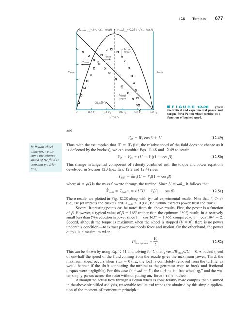
12.8 Turbines 677 ⎥T shaft ⎥ = mr ⋅ β max m V 1 (1– cos ) ⋅ ⎥ W ⎥ = 0.25mV ⋅ 2 shaft max 1 (1– cos β ) Actual power ⋅ Wshaft T shaft ⋅ –W shaft –T shaft U = 0.5V 1 max power Actual torque 0 0.2 V 1 0.4 V 1 0.6 V 1 0.8 V 1 1.0 V 1 U = ω r m F I G U R E 12.28 Typical theoretical and experimental power and torque for a Pelton wheel turbine as a function of bucket speed. and In Pelton wheel analyses, we assume the relative speed of the fluid is constant (no friction). V u2 W 2 cos b U (12.49) Thus, with the assumption that W 1 W 2 1i.e., the relative speed of the fluid does not change as it is deflected by the buckets2, we can combine Eqs. 12.48 and 12.49 to obtain V u2 V u1 1U V 1 211 cos b2 (12.50) This change in tangential component of velocity combined with the torque and power equations developed in Section 12.3 1i.e., Eqs. 12.2 and 12.42 gives T shaft m # r m 1U V 1 211 cos b2 where m # rQ is the mass flowrate through the turbine. Since U vR m , it follows that W # shaft T shaft v m # U1U V 1 211 cos b2 (12.51) These results are plotted in Fig. 12.28 along with typical experimental results. Note that 1i.e., the jet impacts the bucket2, and W # V 1 7 U shaft 6 0 1i.e., the turbine extracts power from the fluid2. Several interesting points can be noted from the above results. First, the power is a function of b. However, a typical value of b 165° 1rather than the optimum 180° 2 results in a relatively small 1less than 2%2 reduction in power since 1 cos 165° 1.966, compared to 1 cos 180° 2. Second, although the torque is maximum when the wheel is stopped 1U 02, there is no power under this condition—to extract power one needs force and motion. On the other hand, the power output is a maximum when U ƒ max power V 1 2 (12.52) This can be shown by using Eq. 12.51 and solving for U that gives dW # shaftdU 0. A bucket speed of one-half the speed of the fluid coming from the nozzle gives the maximum power. Third, the maximum speed occurs when T shaft 0 1i.e., the load is completely removed from the turbine, as would happen if the shaft connecting the turbine to the generator were to break and frictional torques were negligible2. For this case U vR V 1 , the turbine is “free wheeling,” and the water simply passes across the rotor without putting any force on the buckets. Although the actual flow through a Pelton wheel is considerably more complex than assumed in the above simplified analysis, reasonable results and trends are obtained by this simple application of the moment-of-momentum principle.
- Page 650 and 651: 626 Chapter 11 ■ Compressible Flo
- Page 652 and 653: 628 Chapter 11 ■ Compressible Flo
- Page 654 and 655: 630 Chapter 11 ■ Compressible Flo
- Page 656 and 657: 632 Chapter 11 ■ Compressible Flo
- Page 658 and 659: 634 Chapter 11 ■ Compressible Flo
- Page 660 and 661: 636 Chapter 11 ■ Compressible Flo
- Page 662 and 663: 638 Chapter 11 ■ Compressible Flo
- Page 664 and 665: 640 Chapter 11 ■ Compressible Flo
- Page 666 and 667: 642 Chapter 11 ■ Compressible Flo
- Page 668 and 669: 644 Chapter 11 ■ Compressible Flo
- Page 670 and 671: 646 Chapter 12 ■ Turbomachines Ex
- Page 672 and 673: 648 Chapter 12 ■ Turbomachines Q
- Page 674 and 675: 650 Chapter 12 ■ Turbomachines E
- Page 676 and 677: 652 Chapter 12 ■ Turbomachines Th
- Page 678 and 679: 654 Chapter 12 ■ Turbomachines F
- Page 680 and 681: 656 Chapter 12 ■ Turbomachines Co
- Page 682 and 683: 658 Chapter 12 ■ Turbomachines Th
- Page 684 and 685: 660 Chapter 12 ■ Turbomachines 50
- Page 686 and 687: 662 Chapter 12 ■ Turbomachines Si
- Page 688 and 689: 664 Chapter 12 ■ Turbomachines (2
- Page 690 and 691: 666 Chapter 12 ■ Turbomachines cu
- Page 692 and 693: 668 Chapter 12 ■ Turbomachines SO
- Page 694 and 695: 670 Chapter 12 ■ Turbomachines h
- Page 696 and 697: 672 Chapter 12 ■ Turbomachines He
- Page 698 and 699: 674 Chapter 12 ■ Turbomachines Ro
- Page 702 and 703: 678 Chapter 12 ■ Turbomachines E
- Page 704 and 705: 680 Chapter 12 ■ Turbomachines U
- Page 706 and 707: 682 Chapter 12 ■ Turbomachines V1
- Page 708 and 709: 684 Chapter 12 ■ Turbomachines Fo
- Page 710 and 711: 686 Chapter 12 ■ Turbomachines Co
- Page 712 and 713: 688 Chapter 12 ■ Turbomachines Co
- Page 714 and 715: 690 Chapter 12 ■ Turbomachines us
- Page 716 and 717: 692 Chapter 12 ■ Turbomachines es
- Page 718 and 719: 694 Chapter 12 ■ Turbomachines 1
- Page 720 and 721: 696 Chapter 12 ■ Turbomachines 55
- Page 722 and 723: 698 Chapter 12 ■ Turbomachines Se
- Page 724 and 725: 700 Chapter 12 ■ Turbomachines Co
- Page 726 and 727: 702 Appendix A ■ Computational Fl
- Page 728 and 729: 704 Appendix A ■ Computational Fl
- Page 730 and 731: 706 Appendix A ■ Computational Fl
- Page 732 and 733: 708 Appendix A ■ Computational Fl
- Page 734 and 735: 710 Appendix A ■ Computational Fl
- Page 736 and 737: 712 Appendix A ■ Computational Fl
- Page 738 and 739: A ppendix B Physical Properties of
- Page 740 and 741: 716 Appendix B ■ Physical Propert
- Page 742 and 743: 718 Appendix B ■ Physical Propert
- Page 744 and 745: 720 Appendix C ■ Properties of th
- Page 746 and 747: 722 Appendix D ■ Compressible Flo
- Page 748 and 749: 724 Appendix D ■ Compressible Flo
12.8 Turbines 677<br />
⎥T shaft ⎥ = mr<br />
⋅<br />
β<br />
max m V 1 (1– cos )<br />
⋅<br />
⎥ W ⎥ = 0.25mV<br />
⋅ 2<br />
shaft max 1 (1– cos β )<br />
Actual<br />
power<br />
⋅<br />
Wshaft<br />
T shaft<br />
⋅<br />
–W shaft<br />
–T shaft<br />
U = 0.5V 1<br />
max power<br />
Actual<br />
torque<br />
0 0.2 V 1 0.4 V 1 0.6 V 1 0.8 V 1 1.0 V 1<br />
U = ω r m<br />
F I G U R E 12.28 Typical<br />
theoretical and experimental power and<br />
torque for a Pelton wheel turbine as a<br />
function of bucket speed.<br />
and<br />
In Pelton wheel<br />
analyses, we assume<br />
the relative<br />
speed of the <strong>fluid</strong> is<br />
constant (no friction).<br />
V u2 W 2 cos b U<br />
(12.49)<br />
Thus, with the assumption that W 1 W 2 1i.e., the relative speed of the <strong>fluid</strong> does not change as it<br />
is deflected by the buckets2, we can combine Eqs. 12.48 and 12.49 to obtain<br />
V u2 V u1 1U V 1 211 cos b2<br />
(12.50)<br />
This change in tangential component of velocity combined with the torque and power equations<br />
developed in Section 12.3 1i.e., Eqs. 12.2 and 12.42 gives<br />
T shaft m # r m 1U V 1 211 cos b2<br />
where m # rQ is the mass flowrate through the turbine. Since U vR m , it follows that<br />
W # shaft T shaft v m # U1U V 1 211 cos b2<br />
(12.51)<br />
These results are plotted in Fig. 12.28 along with typical experimental results. Note that<br />
1i.e., the jet impacts the bucket2, and W # V 1 7 U<br />
shaft 6 0 1i.e., the turbine extracts power from the <strong>fluid</strong>2.<br />
Several interesting points can be noted from the above results. First, the power is a function<br />
of b. However, a typical value of b 165° 1rather than the optimum 180° 2 results in a relatively<br />
small 1less than 2%2 reduction in power since 1 cos 165° 1.966, compared to 1 cos 180° 2.<br />
Second, although the torque is maximum when the wheel is stopped 1U 02, there is no power<br />
under this condition—to extract power one needs force and motion. On the other hand, the power<br />
output is a maximum when<br />
U ƒ max power V 1<br />
2<br />
(12.52)<br />
This can be shown by using Eq. 12.51 and solving for U that gives dW # shaftdU 0. A bucket speed<br />
of one-half the speed of the <strong>fluid</strong> coming from the nozzle gives the maximum power. Third, the<br />
maximum speed occurs when T shaft 0 1i.e., the load is completely removed from the turbine, as<br />
would happen if the shaft connecting the turbine to the generator were to break and frictional<br />
torques were negligible2. For this case U vR V 1 , the turbine is “free wheeling,” and the water<br />
simply passes across the rotor without putting any force on the buckets.<br />
Although the actual flow through a Pelton wheel is considerably more complex than assumed<br />
in the above simplified analysis, reasonable results and trends are obtained by this simple application<br />
of the moment-of-momentum principle.


