fluid_mechanics
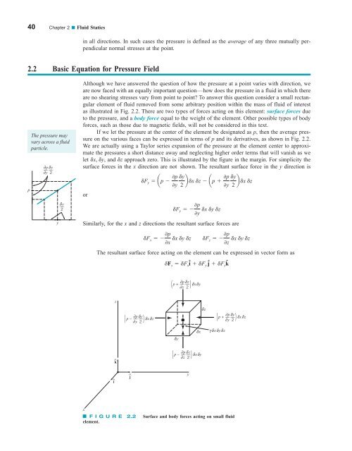
40 Chapter 2 ■ Fluid Statics in all directions. In such cases the pressure is defined as the average of any three mutually perpendicular normal stresses at the point. 2.2 Basic Equation for Pressure Field p The pressure may vary across a fluid particle. ∂p δy ––– ––– ∂y 2 y δ y ––– 2 Although we have answered the question of how the pressure at a point varies with direction, we are now faced with an equally important question—how does the pressure in a fluid in which there are no shearing stresses vary from point to point? To answer this question consider a small rectangular element of fluid removed from some arbitrary position within the mass of fluid of interest as illustrated in Fig. 2.2. There are two types of forces acting on this element: surface forces due to the pressure, and a body force equal to the weight of the element. Other possible types of body forces, such as those due to magnetic fields, will not be considered in this text. If we let the pressure at the center of the element be designated as p, then the average pressure on the various faces can be expressed in terms of p and its derivatives, as shown in Fig. 2.2. We are actually using a Taylor series expansion of the pressure at the element center to approximate the pressures a short distance away and neglecting higher order terms that will vanish as we let dx, dy, and dz approach zero. This is illustrated by the figure in the margin. For simplicity the surface forces in the x direction are not shown. The resultant surface force in the y direction is or dF y ap 0p 0y dF y 0p dx dy dz 0y Similarly, for the x and z directions the resultant surface forces are dy 2 b dx dz ap 0p 0y dF x 0p 0x dx dy dz dF z 0p dx dy dz 0z The resultant surface force acting on the element can be expressed in vector form as dF s dF x î dF y ĵ dF z kˆ dy b dx dz 2 ∂p δ p + δxδy ( ∂ z ) ––– ––– z 2 z ∂p δy p – δxδz ( ––– ––– ∂ y 2 ) δy δx δz γδx ∂p δy p + δxδz ( ––– ––– ∂ y 2 ) δyδz ^ k ∂p δz p – δxδy ( ––– ––– ∂z 2 ) ^ i ^ j y x F I G U R E 2.2 element. Surface and body forces acting on small fluid
2.3 Pressure Variation in a Fluid at Rest 41 The resultant surface force acting on a small fluid element depends only on the pressure gradient if there are no shearing stresses present. or where î, ĵ, and kˆ are the unit vectors along the coordinate axes shown in Fig. 2.2. The group of terms in parentheses in Eq. 2.1 represents in vector form the pressure gradient and can be written as where dF s a 0p 0x î 0p 0y ĵ 0p 0z kˆb dx dy dz 0p 0x î 0p 0y ĵ 0p 0z kˆ §p § 1 2 01 2 0x î 01 2 0y ĵ 01 2 0z kˆ and the symbol § is the gradient or “del” vector operator. Thus, the resultant surface force per unit volume can be expressed as (2.1) Since the z axis is vertical, the weight of the element is where the negative sign indicates that the force due to the weight is downward 1in the negative z direction2. Newton’s second law, applied to the fluid element, can be expressed as where dF represents the resultant force acting on the element, a is the acceleration of the element, and dm is the element mass, which can be written as r dx dy dz. It follows that or and, therefore, dF s dx dy dz §p dwkˆ g dx dy dz kˆ a dF dm a a dF dF s dwkˆ dm a §p dx dy dz g dx dy dz kˆ r dx dy dz a §p gkˆ ra Equation 2.2 is the general equation of motion for a fluid in which there are no shearing stresses. We will use this equation in Section 2.12 when we consider the pressure distribution in a moving fluid. For the present, however, we will restrict our attention to the special case of a fluid at rest. (2.2) 2.3 Pressure Variation in a Fluid at Rest For a fluid at rest a 0 and Eq. 2.2 reduces to or in component form 0p 0x 0 §p gkˆ 0 0p 0y 0 0p 0z g These equations show that the pressure does not depend on x or y. Thus, as we move from point to point in a horizontal plane 1any plane parallel to the x–y plane2, the pressure does not (2.3)
- Page 13 and 14: Preface xi Life Long Learning Probl
- Page 15 and 16: Preface xiii WileyPLUS offers today
- Page 17 and 18: Featured in this Book xv LEARNING O
- Page 19 and 20: C ontents 1 INTRODUCTION 1 Learning
- Page 21 and 22: Contents xix 6.4.3 Irrotational Flo
- Page 23: 12.6 Axial-Flow and Mixed-Flow Pump
- Page 26 and 27: 10 8 Jupiter red spot diameter 2 Ch
- Page 28 and 29: 4 Chapter 1 ■ Introduction and do
- Page 30 and 31: 6 Chapter 1 ■ Introduction up the
- Page 32 and 33: 8 Chapter 1 ■ Introduction the SI
- Page 34 and 35: 10 Chapter 1 ■ Introduction E XAM
- Page 36 and 37: 12 Chapter 1 ■ Introduction TABLE
- Page 38 and 39: 14 Chapter 1 ■ Introduction TABLE
- Page 40 and 41: 16 Chapter 1 ■ Introduction Crude
- Page 42 and 43: 18 Chapter 1 ■ Introduction Visco
- Page 44 and 45: 20 Chapter 1 ■ Introduction Kinem
- Page 46 and 47: 22 Chapter 1 ■ Introduction As th
- Page 48 and 49: 24 Chapter 1 ■ Introduction Boili
- Page 50 and 51: 26 Chapter 1 ■ Introduction E XAM
- Page 52 and 53: 28 Chapter 1 ■ Introduction The r
- Page 54 and 55: 30 Chapter 1 ■ Introduction fluid
- Page 56 and 57: 32 Chapter 1 ■ Introduction Secti
- Page 58 and 59: 34 Chapter 1 ■ Introduction avail
- Page 60 and 61: 36 Chapter 1 ■ Introduction compr
- Page 62 and 63: 2 Fluid Statics CHAPTER OPENING PHO
- Page 66 and 67: 42 Chapter 2 ■ Fluid Statics p Fo
- Page 68 and 69: 44 Chapter 2 ■ Fluid Statics the
- Page 70 and 71: 46 Chapter 2 ■ Fluid Statics p 2
- Page 72 and 73: 48 Chapter 2 ■ Fluid Statics wher
- Page 74 and 75: 50 Chapter 2 ■ Fluid Statics F l
- Page 76 and 77: 52 Chapter 2 ■ Fluid Statics E XA
- Page 78 and 79: 54 Chapter 2 ■ Fluid Statics diff
- Page 80 and 81: 56 Chapter 2 ■ Fluid Statics Bour
- Page 82 and 83: 58 Chapter 2 ■ Fluid Statics Free
- Page 84 and 85: 60 Chapter 2 ■ Fluid Statics The
- Page 86 and 87: 62 Chapter 2 ■ Fluid Statics is t
- Page 88 and 89: 64 Chapter 2 ■ Fluid Statics h 1
- Page 90 and 91: 66 Chapter 2 ■ Fluid Statics SOLU
- Page 92 and 93: 68 Chapter 2 ■ Fluid Statics COMM
- Page 94 and 95: 70 Chapter 2 ■ Fluid Statics V2.8
- Page 96 and 97: 72 Chapter 2 ■ Fluid Statics CG
- Page 98 and 99: 74 Chapter 2 ■ Fluid Statics The
- Page 100 and 101: 76 Chapter 2 ■ Fluid Statics z p
- Page 102 and 103: 78 Chapter 2 ■ Fluid Statics dete
- Page 104 and 105: 80 Chapter 2 ■ Fluid Statics Sect
- Page 106 and 107: 82 Chapter 2 ■ Fluid Statics Vapo
- Page 108 and 109: 84 Chapter 2 ■ Fluid Statics heig
- Page 110 and 111: 86 Chapter 2 ■ Fluid Statics h 4
- Page 112 and 113: 88 Chapter 2 ■ Fluid Statics 2.81
40 Chapter 2 ■ Fluid Statics<br />
in all directions. In such cases the pressure is defined as the average of any three mutually perpendicular<br />
normal stresses at the point.<br />
2.2 Basic Equation for Pressure Field<br />
p<br />
The pressure may<br />
vary across a <strong>fluid</strong><br />
particle.<br />
∂p<br />
δy<br />
––– –––<br />
∂y 2<br />
y<br />
δ y ––– 2<br />
Although we have answered the question of how the pressure at a point varies with direction, we<br />
are now faced with an equally important question—how does the pressure in a <strong>fluid</strong> in which there<br />
are no shearing stresses vary from point to point? To answer this question consider a small rectangular<br />
element of <strong>fluid</strong> removed from some arbitrary position within the mass of <strong>fluid</strong> of interest<br />
as illustrated in Fig. 2.2. There are two types of forces acting on this element: surface forces due<br />
to the pressure, and a body force equal to the weight of the element. Other possible types of body<br />
forces, such as those due to magnetic fields, will not be considered in this text.<br />
If we let the pressure at the center of the element be designated as p, then the average pressure<br />
on the various faces can be expressed in terms of p and its derivatives, as shown in Fig. 2.2.<br />
We are actually using a Taylor series expansion of the pressure at the element center to approximate<br />
the pressures a short distance away and neglecting higher order terms that will vanish as we<br />
let dx, dy, and dz approach zero. This is illustrated by the figure in the margin. For simplicity the<br />
surface forces in the x direction are not shown. The resultant surface force in the y direction is<br />
or<br />
dF y ap 0p<br />
0y<br />
dF y 0p dx dy dz<br />
0y<br />
Similarly, for the x and z directions the resultant surface forces are<br />
dy<br />
2<br />
b dx dz ap <br />
0p<br />
0y<br />
dF x 0p<br />
0x dx dy dz dF z 0p dx dy dz<br />
0z<br />
The resultant surface force acting on the element can be expressed in vector form as<br />
dF s dF x î dF y ĵ dF z kˆ<br />
dy<br />
b dx dz<br />
2<br />
∂p<br />
δ<br />
p + δxδy<br />
( ∂ z ) ––– ––– z<br />
2<br />
z<br />
∂p<br />
δy<br />
p – δxδz<br />
(<br />
––– –––<br />
∂ y 2 )<br />
δy<br />
δx<br />
δz<br />
γδx<br />
∂p<br />
δy<br />
p + δxδz<br />
(<br />
––– –––<br />
∂ y 2 )<br />
δyδz<br />
^<br />
k<br />
∂p<br />
δz<br />
p – δxδy<br />
(<br />
––– –––<br />
∂z<br />
2 )<br />
^<br />
i<br />
^<br />
j<br />
y<br />
x<br />
F I G U R E 2.2<br />
element.<br />
Surface and body forces acting on small <strong>fluid</strong>


