fluid_mechanics
600 Chapter 11 ■ Compressible Flow Finally from Eq. 1 we have (Ans) (b) For p re 40 kPa1abs2 53.3 kPa1abs2 p*, we have p th p* 53.3 kPa1abs2 and Ma th 1. The converging duct is choked. From Eq. 2 1see also Eq. 11.662 or From Eq. 5 1see also Eq. 11.642, or m # 11.04 kgm 3 211 10 4 m 2 21193 ms2 0.0201 kgs r th 1.23 kgm 3 e 1 1 311.4 1224112 2 f 111.412 r th 0.780 kgm 3 T th 288 K 1 1 311.4 1224112 2 T th 240 K From Eq. 4, V th 112 23286.9 J1kg # K241240 K211.42 310 1Jkg2 12 310 ms since 1 Jkg 1 N # mkg 1 1kg # ms 2 2 # mkg 1ms2 2 . Finally from Eq. 1 m # 10.780 kgm 3 211 10 4 m 2 21310 ms2 0.0242 kgs (Ans) From the values of throat temperature and throat pressure calculated above for flow situations 1a2 and 1b2, we can construct the temperature–entropy diagram shown in Fig. E11.5b. COMMENT Note that the flow from standard atmosphere to the receiver for receiver pressure, p re , greater than or equal to the critical pressure, p*, is isentropic. When the receiver pressure is less than the critical pressure as in situation 1b2 above, what is the flow like downstream from the exit of the converging duct? Experience suggests that this flow, when p re 6 p*, is threedimensional and nonisentropic and involves a drop in pressure from p th to p re , a drop in temperature, and an increase of entropy as are indicated in Fig. E11.5c. Isentropic flow Eqs. 11.56, 11.59, and 11.60 have been used to construct Fig. D.1 in Appendix D for air 1k 1.42. Examples 11.6 and 11.7 illustrate how these graphs of TT 0 , pp 0 , and rr 0 as a function of Mach number, Ma, can be used to solve compressible flow problems. E XAMPLE 11.6 Use of Compressible Flow Graphs in Solving Problems GIVEN Consider the flow described in Example 11.5. duct throat to solve for mass flowrate from m # r th A th V th (1) T th 10.9421288 K2 271 K FIND Solve Example 11.5 using Fig. D.1 of Appendix D. SOLUTION We still need the density and velocity of the air at the converging Thus, from Eqs. 2 and 3 (a) Since the receiver pressure, p re 80 kPa1abs2, is greater and than the critical pressure, p* 53.3 kPa1abs2, the throat pressure, r th 10.85211.23 kgm 3 2 1.04 kgm 3 p th , is equal to the receiver pressure. Thus Furthermore, using Eqs. 11.36 and 11.46 we get p th 80 kPa1abs2 p 0 101 kPa1abs2 0.792 From Fig. D.1, for pp 0 0.79, we get from the graph Ma th 0.59 T th 0.94 T 0 r th 0.85 r 0 (2) (3) V th Ma th 2RT th k 10.592 23286.9 J1kg # K241269 K211.42 194 1Jkg2 12 194 ms since 1 Jkg 1 N # mkg 1 1kg # ms 2 2 # mkg 1ms2 2 . Finally, from Eq. 1 m # 11.04 kgm 3 211 10 4 m 2 21194 ms2 0.0202 kgs (Ans)
11.4 Isentropic Flow of an Ideal Gas 601 (b) For p re 40 kPa1abs2 6 53.3 kPa1abs2 p*, the throat pressure is equal to 53.3 kPa1abs2 and the duct is choked with Ma th 1. From Fig. D.1, for Ma 1 we get and From Eqs. 4 and 5 we obtain and T th T 0 0.83 r th r 0 0.64 T th 10.8321288 K2 240 K r th 10.64211.23 kgm 3 2 0.79 kgm 3 (4) (5) Also, from Eqs. 11.36 and 11.46 we conclude that Then, from Eq. 1 V th Ma th 2RT th k 112 23286.9 J1kg # K241240 K211.42 310 1Jkg2 12 310 ms m # 10.79 kgm 3 211 10 4 m 2 21310 ms2 0.024 kgs (Ans) COMMENT The values from Fig. D.1 resulted in answers for mass flowrate that are close to those using the ideal gas equations 1see Example 11.52. The temperature–entropy diagrams remain the same as those provided in the solution of Example 11.5. E XAMPLE 11.7 Static to Stagnation Pressure Ratio GIVEN The static pressure to stagnation pressure ratio at a point in a flow stream is measured with a Pitot-static tube 1see Fig. 3.62 as being equal to 0.82. The stagnation temperature of the fluid is 68 °F. Determine the flow velocity if the fluid is 1a2 air, 1b2 he- FIND lium. SOLUTION We consider both air and helium, flowing as described above, to act as ideal gases with constant specific heats. Then, we can use any of the ideal gas relationships developed in this chapter. To determine the flow velocity, we can combine Eqs. 11.36 and 11.46 to obtain By knowing the value of static to stagnation pressure ratio, pp 0 , and the specific heat ratio we can obtain the corresponding Mach number from Eq. 11.59, or for air, from Fig. D.1. Figure D.1 cannot be used for helium, since k for helium is 1.66 and Fig. D.1 is for k 1.4 only. With Mach number, specific heat ratio, and stagnation temperature known, the value of static temperature can be subsequently ascertained from Eq. 11.56 1or Fig. D.1 for air2. (a) For air, pp 0 0.82; thus from Fig. D.1, and Then, from Eq. 3 V Ma 2RTk Ma 0.54 T T 0 0.94 T 10.9423168 4602 °R4 496 °R (1) (2) (3) (4) and using Eqs. 1, 2, and 4 we get Thus, since 1 lb 32.2 lbm # fts 2 , it follows that (Ans) (b) For helium, pp 0 0.82 and k 1.66. By substituting these values into Eq. 11.59 we get or From Eq. 11.56 we obtain Thus, V 10.542 2353.3 1ft # lb21lbm # °R241496 °R211.42 104 1ft # lblbm2 1 2 V 104 1ft # lblbm2 1 2 3132.2 lbm # fts 2 2lb4 1 2 590 fts 1.6611.6612 1 0.82 e 1 311.66 1224 Ma f 2 T T 0 Ma 0.499 1 1 31k 1224Ma 2 1 T e f3168 4602 °R4 2 1 311.66 122410.4992 488 °R
- Page 574 and 575: 550 Chapter 10 ■ Open-Channel Flo
- Page 576 and 577: 552 Chapter 10 ■ Open-Channel Flo
- Page 578 and 579: 554 Chapter 10 ■ Open-Channel Flo
- Page 580 and 581: 556 Chapter 10 ■ Open-Channel Flo
- Page 582 and 583: 558 Chapter 10 ■ Open-Channel Flo
- Page 584 and 585: 560 Chapter 10 ■ Open-Channel Flo
- Page 586 and 587: 562 Chapter 10 ■ Open-Channel Flo
- Page 588 and 589: 564 Chapter 10 ■ Open-Channel Flo
- Page 590 and 591: 566 Chapter 10 ■ Open-Channel Flo
- Page 592 and 593: 568 Chapter 10 ■ Open-Channel Flo
- Page 594 and 595: 570 Chapter 10 ■ Open-Channel Flo
- Page 596 and 597: 572 Chapter 10 ■ Open-Channel Flo
- Page 598 and 599: 574 Chapter 10 ■ Open-Channel Flo
- Page 600 and 601: 576 Chapter 10 ■ Open-Channel Flo
- Page 602 and 603: 578 Chapter 10 ■ Open-Channel Flo
- Page 604 and 605: 580 Chapter 11 ■ Compressible Flo
- Page 606 and 607: 582 Chapter 11 ■ Compressible Flo
- Page 608 and 609: 584 Chapter 11 ■ Compressible Flo
- Page 610 and 611: 586 Chapter 11 ■ Compressible Flo
- Page 612 and 613: 588 Chapter 11 ■ Compressible Flo
- Page 614 and 615: 590 Chapter 11 ■ Compressible Flo
- Page 616 and 617: 592 Chapter 11 ■ Compressible Flo
- Page 618 and 619: 594 Chapter 11 ■ Compressible Flo
- Page 620 and 621: 596 Chapter 11 ■ Compressible Flo
- Page 622 and 623: 598 Chapter 11 ■ Compressible Flo
- Page 626 and 627: 602 Chapter 11 ■ Compressible Flo
- Page 628 and 629: 604 Chapter 11 ■ Compressible Flo
- Page 630 and 631: 606 Chapter 11 ■ Compressible Flo
- Page 632 and 633: 608 Chapter 11 ■ Compressible Flo
- Page 634 and 635: 610 Chapter 11 ■ Compressible Flo
- Page 636 and 637: 612 Chapter 11 ■ Compressible Flo
- Page 638 and 639: 614 Chapter 11 ■ Compressible Flo
- Page 640 and 641: 616 Chapter 11 ■ Compressible Flo
- Page 642 and 643: 618 Chapter 11 ■ Compressible Flo
- Page 644 and 645: 620 Chapter 11 ■ Compressible Flo
- Page 646 and 647: 622 Chapter 11 ■ Compressible Flo
- Page 648 and 649: 624 Chapter 11 ■ Compressible Flo
- Page 650 and 651: 626 Chapter 11 ■ Compressible Flo
- Page 652 and 653: 628 Chapter 11 ■ Compressible Flo
- Page 654 and 655: 630 Chapter 11 ■ Compressible Flo
- Page 656 and 657: 632 Chapter 11 ■ Compressible Flo
- Page 658 and 659: 634 Chapter 11 ■ Compressible Flo
- Page 660 and 661: 636 Chapter 11 ■ Compressible Flo
- Page 662 and 663: 638 Chapter 11 ■ Compressible Flo
- Page 664 and 665: 640 Chapter 11 ■ Compressible Flo
- Page 666 and 667: 642 Chapter 11 ■ Compressible Flo
- Page 668 and 669: 644 Chapter 11 ■ Compressible Flo
- Page 670 and 671: 646 Chapter 12 ■ Turbomachines Ex
- Page 672 and 673: 648 Chapter 12 ■ Turbomachines Q
600 Chapter 11 ■ Compressible Flow<br />
Finally from Eq. 1 we have<br />
(Ans)<br />
(b) For p re 40 kPa1abs2 53.3 kPa1abs2 p*, we have<br />
p th p* 53.3 kPa1abs2 and Ma th 1. The converging duct is<br />
choked. From Eq. 2 1see also Eq. 11.662<br />
or<br />
From Eq. 5 1see also Eq. 11.642,<br />
or<br />
m # 11.04 kgm 3 211 10 4 m 2 21193 ms2<br />
0.0201 kgs<br />
r th<br />
1.23 kgm 3 e 1<br />
1 311.4 1224112 2 f 111.412<br />
r th 0.780 kgm 3<br />
T th<br />
288 K 1<br />
1 311.4 1224112 2<br />
T th 240 K<br />
From Eq. 4,<br />
V th 112 23286.9 J1kg # K241240 K211.42<br />
310 1Jkg2 12 310 ms<br />
since 1 Jkg 1 N # mkg 1 1kg # ms 2 2 # mkg 1ms2 2 . Finally<br />
from Eq. 1<br />
m # 10.780 kgm 3 211 10 4 m 2 21310 ms2<br />
0.0242 kgs<br />
(Ans)<br />
From the values of throat temperature and throat pressure calculated<br />
above for flow situations 1a2 and 1b2, we can construct the<br />
temperature–entropy diagram shown in Fig. E11.5b.<br />
COMMENT Note that the flow from standard atmosphere to<br />
the receiver for receiver pressure, p re , greater than or equal to the<br />
critical pressure, p*, is isentropic. When the receiver pressure is<br />
less than the critical pressure as in situation 1b2 above, what is the<br />
flow like downstream from the exit of the converging duct? Experience<br />
suggests that this flow, when p re 6 p*, is threedimensional<br />
and nonisentropic and involves a drop in pressure<br />
from p th to p re , a drop in temperature, and an increase of entropy<br />
as are indicated in Fig. E11.5c.<br />
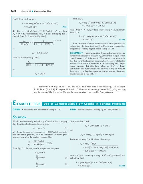
Isentropic flow Eqs. 11.56, 11.59, and 11.60 have been used to construct Fig. D.1 in Appendix<br />
D for air 1k 1.42. Examples 11.6 and 11.7 illustrate how these graphs of TT 0 , pp 0 , and rr 0<br />
as a function of Mach number, Ma, can be used to solve compressible flow problems.<br />
E XAMPLE 11.6<br />
Use of Compressible Flow Graphs in Solving Problems<br />
GIVEN Consider the flow described in Example 11.5.<br />
duct throat to solve for mass flowrate from<br />
m # r th A th V th (1)<br />
T th 10.9421288 K2 271 K<br />
FIND Solve Example 11.5 using Fig. D.1 of Appendix D.<br />
SOLUTION<br />
We still need the density and velocity of the air at the converging Thus, from Eqs. 2 and 3<br />
(a) Since the receiver pressure, p re 80 kPa1abs2, is greater<br />
and<br />
than the critical pressure, p* 53.3 kPa1abs2, the throat pressure,<br />
r th 10.85211.23 kgm 3 2 1.04 kgm 3<br />
p th , is equal to the receiver pressure. Thus<br />
Furthermore, using Eqs. 11.36 and 11.46 we get<br />
p th 80 kPa1abs2<br />
<br />
p 0 101 kPa1abs2 0.792<br />
From Fig. D.1, for pp 0 0.79, we get from the graph<br />
Ma th 0.59<br />
T th<br />
0.94<br />
T 0<br />
r th<br />
0.85<br />
r 0<br />
(2)<br />
(3)<br />
V th Ma th 2RT th k<br />
10.592 23286.9 J1kg # K241269 K211.42<br />
194 1Jkg2 12 194 ms<br />
since 1 Jkg 1 N # mkg 1 1kg # ms 2 2 # mkg 1ms2 2 . Finally,<br />
from Eq. 1<br />
m # 11.04 kgm 3 211 10 4 m 2 21194 ms2<br />
0.0202 kgs<br />
(Ans)


