fluid_mechanics
594 Chapter 11 ■ Compressible Flow A converging duct will decelerate a supersonic flow and accelerate a subsonic flow. Equations 11.42 and 11.47 merge to form dV V dA A (11.48) We can use Eq. 11.48 to conclude that when the flow is subsonic 1Ma 6 12, velocity and section area changes are in opposite directions. In other words, the area increase associated with subsonic flow through a diverging duct like the one shown in Fig. 11.5a is accompanied by a velocity decrease. Subsonic flow through a converging duct 1see Fig. 11.5b2 involves an increase of velocity. These trends are consistent with incompressible flow behavior, which we described earlier in this book, for instance, in Chapters 3 and 8. Equation 11.48 also serves to show us that when the flow is supersonic 1Ma 7 12, velocity and area changes are in the same direction. A diverging duct 1Fig. 11.5a2 will accelerate a supersonic flow. A converging duct 1Fig. 11.5b2 will decelerate a supersonic flow. These trends are the opposite of what happens for incompressible and subsonic compressible flows. To better understand why subsonic and supersonic duct flows are so different, we combine Eqs. 11.44 and 11.48 to form dr r dA A 1 11 Ma 2 2 Ma 2 11 Ma 2 2 (11.49) Using Eq. 11.49, we can conclude that for subsonic flows 1Ma 6 12, density and area changes are in the same direction, whereas for supersonic flows 1Ma 7 12, density and area changes are in opposite directions. Since rAV must remain constant 1Eq. 11.402, when the duct diverges and the flow is subsonic, density and area both increase and thus flow velocity must decrease. However, for supersonic flow through a diverging duct, when the area increases, the density decreases enough so that the flow velocity has to increase to keep rAV constant. By rearranging Eq. 11.48, we can obtain dA dV A V 11 Ma2 2 (11.50) Equation 11.50 gives us some insight into what happens when Ma 1. For Ma 1, Eq. 11.50 requires that dAdV 0. This result suggests that the area associated with Ma 1 is either a minimum or a maximum amount. A converging–diverging duct 1Fig. 11.6a and margin photograph2 involves a minimum area. If the flow entering such a duct were subsonic, Eq. 11.48 discloses that the fluid velocity would increase in the converging portion of the duct, and achievement of a sonic condition 1Ma 12 at the minimum area location appears possible. If the flow entering the converging–diverging duct is supersonic, Eq. 11.48 states that the fluid velocity would decrease in the converging portion of the duct and the sonic condition at the minimum area is possible. Flow Subsonic flow (Ma < 1) dA > 0 dV < 0 Supersonic flow (Ma > 1) dA > 0 dV > 0 (a) dA < 0 dV > 0 dA < 0 dV < 0 Flow (b) F I G U R E 11.5 (a) A diverging duct. (b) A converging duct.
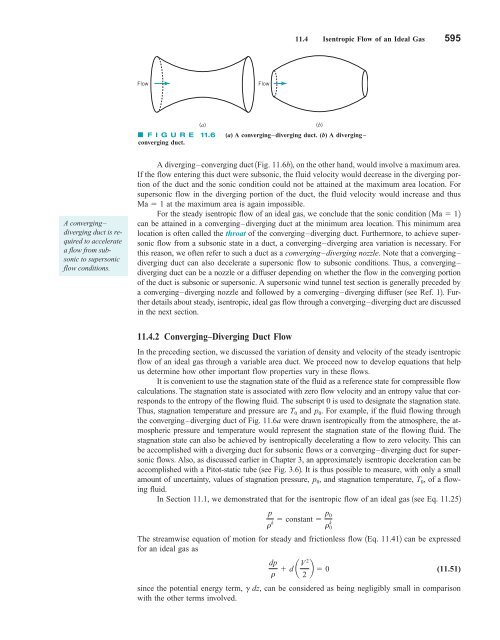
11.4 Isentropic Flow of an Ideal Gas 595 Flow Flow (a) F I G U R E 11.6 (a) A converging–diverging duct. (b) A diverging – converging duct. (b) A converging– diverging duct is required to accelerate a flow from subsonic to supersonic flow conditions. A diverging–converging duct 1Fig. 11.6b2, on the other hand, would involve a maximum area. If the flow entering this duct were subsonic, the fluid velocity would decrease in the diverging portion of the duct and the sonic condition could not be attained at the maximum area location. For supersonic flow in the diverging portion of the duct, the fluid velocity would increase and thus Ma 1 at the maximum area is again impossible. For the steady isentropic flow of an ideal gas, we conclude that the sonic condition can be attained in a converging–diverging duct at the minimum area location. This minimum area location is often called the throat of the converging–diverging duct. Furthermore, to achieve supersonic flow from a subsonic state in a duct, a converging–diverging area variation is necessary. For this reason, we often refer to such a duct as a converging–diverging nozzle. Note that a converging– diverging duct can also decelerate a supersonic flow to subsonic conditions. Thus, a converging– diverging duct can be a nozzle or a diffuser depending on whether the flow in the converging portion of the duct is subsonic or supersonic. A supersonic wind tunnel test section is generally preceded by a converging–diverging nozzle and followed by a converging–diverging diffuser 1see Ref. 12. Further details about steady, isentropic, ideal gas flow through a converging–diverging duct are discussed in the next section. 1Ma 12 11.4.2 Converging–Diverging Duct Flow In the preceding section, we discussed the variation of density and velocity of the steady isentropic flow of an ideal gas through a variable area duct. We proceed now to develop equations that help us determine how other important flow properties vary in these flows. It is convenient to use the stagnation state of the fluid as a reference state for compressible flow calculations. The stagnation state is associated with zero flow velocity and an entropy value that corresponds to the entropy of the flowing fluid. The subscript 0 is used to designate the stagnation state. Thus, stagnation temperature and pressure are T 0 and p 0 . For example, if the fluid flowing through the converging–diverging duct of Fig. 11.6a were drawn isentropically from the atmosphere, the atmospheric pressure and temperature would represent the stagnation state of the flowing fluid. The stagnation state can also be achieved by isentropically decelerating a flow to zero velocity. This can be accomplished with a diverging duct for subsonic flows or a converging–diverging duct for supersonic flows. Also, as discussed earlier in Chapter 3, an approximately isentropic deceleration can be accomplished with a Pitot-static tube 1see Fig. 3.62. It is thus possible to measure, with only a small amount of uncertainty, values of stagnation pressure, p 0 , and stagnation temperature, T 0 , of a flowing fluid. In Section 11.1, we demonstrated that for the isentropic flow of an ideal gas 1see Eq. 11.252 p r constant p 0 k r k 0 The streamwise equation of motion for steady and frictionless flow 1Eq. 11.412 can be expressed for an ideal gas as dp (11.51) r d aV2 2 b 0 since the potential energy term, g dz, can be considered as being negligibly small in comparison with the other terms involved.
- Page 568 and 569: 544 Chapter 10 ■ Open-Channel Flo
- Page 570 and 571: 546 Chapter 10 ■ Open-Channel Flo
- Page 572 and 573: 548 Chapter 10 ■ Open-Channel Flo
- Page 574 and 575: 550 Chapter 10 ■ Open-Channel Flo
- Page 576 and 577: 552 Chapter 10 ■ Open-Channel Flo
- Page 578 and 579: 554 Chapter 10 ■ Open-Channel Flo
- Page 580 and 581: 556 Chapter 10 ■ Open-Channel Flo
- Page 582 and 583: 558 Chapter 10 ■ Open-Channel Flo
- Page 584 and 585: 560 Chapter 10 ■ Open-Channel Flo
- Page 586 and 587: 562 Chapter 10 ■ Open-Channel Flo
- Page 588 and 589: 564 Chapter 10 ■ Open-Channel Flo
- Page 590 and 591: 566 Chapter 10 ■ Open-Channel Flo
- Page 592 and 593: 568 Chapter 10 ■ Open-Channel Flo
- Page 594 and 595: 570 Chapter 10 ■ Open-Channel Flo
- Page 596 and 597: 572 Chapter 10 ■ Open-Channel Flo
- Page 598 and 599: 574 Chapter 10 ■ Open-Channel Flo
- Page 600 and 601: 576 Chapter 10 ■ Open-Channel Flo
- Page 602 and 603: 578 Chapter 10 ■ Open-Channel Flo
- Page 604 and 605: 580 Chapter 11 ■ Compressible Flo
- Page 606 and 607: 582 Chapter 11 ■ Compressible Flo
- Page 608 and 609: 584 Chapter 11 ■ Compressible Flo
- Page 610 and 611: 586 Chapter 11 ■ Compressible Flo
- Page 612 and 613: 588 Chapter 11 ■ Compressible Flo
- Page 614 and 615: 590 Chapter 11 ■ Compressible Flo
- Page 616 and 617: 592 Chapter 11 ■ Compressible Flo
- Page 620 and 621: 596 Chapter 11 ■ Compressible Flo
- Page 622 and 623: 598 Chapter 11 ■ Compressible Flo
- Page 624 and 625: 600 Chapter 11 ■ Compressible Flo
- Page 626 and 627: 602 Chapter 11 ■ Compressible Flo
- Page 628 and 629: 604 Chapter 11 ■ Compressible Flo
- Page 630 and 631: 606 Chapter 11 ■ Compressible Flo
- Page 632 and 633: 608 Chapter 11 ■ Compressible Flo
- Page 634 and 635: 610 Chapter 11 ■ Compressible Flo
- Page 636 and 637: 612 Chapter 11 ■ Compressible Flo
- Page 638 and 639: 614 Chapter 11 ■ Compressible Flo
- Page 640 and 641: 616 Chapter 11 ■ Compressible Flo
- Page 642 and 643: 618 Chapter 11 ■ Compressible Flo
- Page 644 and 645: 620 Chapter 11 ■ Compressible Flo
- Page 646 and 647: 622 Chapter 11 ■ Compressible Flo
- Page 648 and 649: 624 Chapter 11 ■ Compressible Flo
- Page 650 and 651: 626 Chapter 11 ■ Compressible Flo
- Page 652 and 653: 628 Chapter 11 ■ Compressible Flo
- Page 654 and 655: 630 Chapter 11 ■ Compressible Flo
- Page 656 and 657: 632 Chapter 11 ■ Compressible Flo
- Page 658 and 659: 634 Chapter 11 ■ Compressible Flo
- Page 660 and 661: 636 Chapter 11 ■ Compressible Flo
- Page 662 and 663: 638 Chapter 11 ■ Compressible Flo
- Page 664 and 665: 640 Chapter 11 ■ Compressible Flo
- Page 666 and 667: 642 Chapter 11 ■ Compressible Flo
11.4 Isentropic Flow of an Ideal Gas 595<br />
Flow<br />
Flow<br />
(a)<br />
F I G U R E 11.6 (a) A converging–diverging duct. (b) A diverging –<br />
converging duct.<br />
(b)<br />
A converging–<br />
diverging duct is required<br />
to accelerate<br />
a flow from subsonic<br />
to supersonic<br />
flow conditions.<br />
A diverging–converging duct 1Fig. 11.6b2, on the other hand, would involve a maximum area.<br />
If the flow entering this duct were subsonic, the <strong>fluid</strong> velocity would decrease in the diverging portion<br />
of the duct and the sonic condition could not be attained at the maximum area location. For<br />
supersonic flow in the diverging portion of the duct, the <strong>fluid</strong> velocity would increase and thus<br />
Ma 1 at the maximum area is again impossible.<br />
For the steady isentropic flow of an ideal gas, we conclude that the sonic condition<br />
can be attained in a converging–diverging duct at the minimum area location. This minimum area<br />
location is often called the throat of the converging–diverging duct. Furthermore, to achieve supersonic<br />
flow from a subsonic state in a duct, a converging–diverging area variation is necessary. For<br />
this reason, we often refer to such a duct as a converging–diverging nozzle. Note that a converging–<br />
diverging duct can also decelerate a supersonic flow to subsonic conditions. Thus, a converging–<br />
diverging duct can be a nozzle or a diffuser depending on whether the flow in the converging portion<br />
of the duct is subsonic or supersonic. A supersonic wind tunnel test section is generally preceded by<br />
a converging–diverging nozzle and followed by a converging–diverging diffuser 1see Ref. 12. Further<br />
details about steady, isentropic, ideal gas flow through a converging–diverging duct are discussed<br />
in the next section.<br />
1Ma 12<br />
11.4.2 Converging–Diverging Duct Flow<br />
In the preceding section, we discussed the variation of density and velocity of the steady isentropic<br />
flow of an ideal gas through a variable area duct. We proceed now to develop equations that help<br />
us determine how other important flow properties vary in these flows.<br />
It is convenient to use the stagnation state of the <strong>fluid</strong> as a reference state for compressible flow<br />
calculations. The stagnation state is associated with zero flow velocity and an entropy value that corresponds<br />
to the entropy of the flowing <strong>fluid</strong>. The subscript 0 is used to designate the stagnation state.<br />
Thus, stagnation temperature and pressure are T 0 and p 0 . For example, if the <strong>fluid</strong> flowing through<br />
the converging–diverging duct of Fig. 11.6a were drawn isentropically from the atmosphere, the atmospheric<br />
pressure and temperature would represent the stagnation state of the flowing <strong>fluid</strong>. The<br />
stagnation state can also be achieved by isentropically decelerating a flow to zero velocity. This can<br />
be accomplished with a diverging duct for subsonic flows or a converging–diverging duct for supersonic<br />
flows. Also, as discussed earlier in Chapter 3, an approximately isentropic deceleration can be<br />
accomplished with a Pitot-static tube 1see Fig. 3.62. It is thus possible to measure, with only a small<br />
amount of uncertainty, values of stagnation pressure, p 0 , and stagnation temperature, T 0 , of a flowing<br />
<strong>fluid</strong>.<br />
In Section 11.1, we demonstrated that for the isentropic flow of an ideal gas 1see Eq. 11.252<br />
p<br />
r constant p 0<br />
k r k 0<br />
The streamwise equation of motion for steady and frictionless flow 1Eq. 11.412 can be expressed<br />
for an ideal gas as<br />
dp<br />
(11.51)<br />
r d aV2 2 b 0<br />
since the potential energy term, g dz, can be considered as being negligibly small in comparison<br />
with the other terms involved.


