fluid_mechanics
576 Chapter 10 ■ Open-Channel Flow during a heavy rain storm. The cross section of the gutter is shown in Fig. P10.85. Determine the vertical distance that this gutter must be pitched 1i.e., the difference in elevation between the two ends of the gutter2 so that the water does not overflow the gutter. Assume uniform depth channel flow. Section 10.6.1 The Hydraulic Jump (Also see Lab Problems 10.116 and 10.117.) 10.86 Obtain a photographimage of a situation that involves a hydraulic jump. Print this photo and write a brief paragraph that describes the flow. 10.87 Water flows upstream of a hydraulic jump with a depth of 0.5 m and a velocity of 6 ms. Determine the depth of the water downstream of the jump. 10.88 A 2.0-ft standing wave is produced at the bottom of the rectangular channel in an amusement park water ride. If the water depth upstream of the wave is estimated to be 1.5 ft, determine how fast the boat is traveling when it passes through this standing wave 1hydraulic jump2 for its final “splash.” 10.89 The water depths upstream and downstream of a hydraulic jump are 0.3 and 1.2 m, respectively. Determine the upstream velocity and the power dissipated if the channel is 50 m wide. 10.90 Under appropriate conditions, water flowing from a faucet, onto a flat plate, and over the edge of the plate can produce a circular hydraulic jump as shown in Fig. P10.90 and Video V10.12. Consider a situation where a jump forms 3.0 in. from the center of the plate with depths upstream and downstream of the jump of 0.05 in. and 0.20 in., respectively. Determine the flowrate from the faucet. Jump F I G U R E P10.90 3 in. Jump 0.05 in. 0.20 in. 10.91 Show that the Froude number downstream of a hydraulic jump in a rectangular channel is 1y 1y 2 2 3 /2 times the Froude number upstream of the jump, where (1) and (2) denote the upstream and downstream conditions, respectively. 10.92 Water flows in a 2-ft-wide rectangular channel at a rate of 10 ft 3 s. If the water depth downstream of a hydraulic jump is 2.5 ft, determine (a) the water depth upstream of the jump, (b) the upstream and downstream Froude numbers, and (c) the head loss across the jump. 10.93 A hydraulic jump at the base of a spillway of a dam is such that the depths upstream and downstream of the jump are 0.90 and 3.6 m, respectively (see Video V10.11). If the spillway is 10 m wide, what is the flowrate over the spillway? 10.94 Determine the head loss and power dissipated by the hydraulic jump of Problem 10.93. 10.95 A hydraulic jump occurs in a 4-m-wide rectangular channel at a point where the slope changes from 3 m per 100 m upstream of the jump to h m per 100 m downstream of the jump. The depth and velocity of the uniform flow upstream of the jump are 0.5 m and 8 ms, respectively. Determine the value of h if the flow downstream of the jump is to be uniform flow. 10.96 At a given location in a 12-ft-wide rectangular channel the flowrate is 900 ft 3 s and the depth is 4 ft. Is this location upstream or downstream of the hydraulic jump that occurs in this channel? Explain. *10.97 A rectangular channel of width b is to carry water at flowrates from 30 Q 600 cfs. The water depth upstream of the hydraulic jump that occurs 1if one does occur2 is to remain 1.5 ft for all cases. Plot the power dissipated in the jump as a function of flowrate for channels of width b 10, 20, 30, and 40 ft. 10.98 Water flows in a rectangular channel at a depth of y 1 ft and a velocity of V 20 fts. When a gate is suddenly placed across the end of the channel, a wave 1a moving hydraulic jump2 travels upstream with velocity V w as is indicated in Fig. P10.98. Determine V w . Note that this is an unsteady problem for a stationary observer. However, for an observer moving to the left with velocity V w , the flow appears as a steady hydraulic jump. V y V w V = 0 F I G U R E P10.98 10.99 Water flows in a rectangular channel with velocity V 6 ms. A gate at the end of the channel is suddenly closed so that a wave (a moving hydraulic jump) travels upstream with velocity V w 2 ms as is indicated in Fig. P10.98. Determine the depths ahead of and behind the wave. Note that this is an unsteady problem for a stationary observer. However, for an observer moving to the left with velocity V w , the flow appears as a steady hydraulic jump. 10.100 (See Fluids in the News article titled “Grand Canyon rapids building,” Section 10.6.1.) During the flood of 1983, a large hydraulic jump formed at “Crystal Hole” rapid on the Colorado River. People rafting the river at that time report “entering the rapid at almost 30 mph, hitting a 20-ft-tall wall of water, and exiting at about 10 mph.” Is this information (i.e., upstream and downstream velocities and change in depth) consistent with the principles of a hydraulic jump? Show calculations to support your answer. Section 10.6.2,3 Sharp-Crested and Broad-Crested Weirs (Also see Lab Problems 10.114 and 10.115.) 10.101 Obtain a photographimage of a situation that involves a weir. Print this photo and write a brief paragraph that describes the flow. 10.102 Water flows over a 2-m-wide rectangular sharp-crested weir. Determine the flowrate if the weir head is 0.1 m and the channel depth is 1 m. 10.103 Water flows over a 5-ft-wide, rectangular sharp-crested weir that is P w 4.5 ft tall. If the depth upstream is 5 ft, determine the flowrate. 10.104 A rectangular sharp-crested weir is used to measure the flowrate in a channel of width 10 ft. It is desired to have the channel flow depth be 6 ft when the flowrate is 50 cfs. Determine the height, P w , of the weir plate.
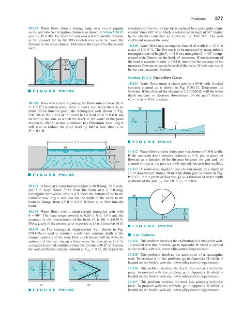
Problems 577 10.105 Water flows from a storage tank, over two triangular weirs, and into two irrigation channels as shown in Video V10.13 and Fig. P10.105. The head for each weir is 0.4 ft, and the flowrate in the channel fed by the 90°-V-notch weir is to be twice the flowrate in the other channel. Determine the angle u for the second weir. 90° 0.4 ft F I G U R E P10.105 θ 10.106 Rain water from a parking lot flows into a 2-acre 18.71 10 4 ft 2 2 retention pond. After a heavy rain when there is no more inflow into the pond, the rectangular weir shown in Fig. P10.106 at the outlet of the pond has a head of H 0.6 ft. (a) Determine the rate at which the level of the water in the pond decreases, dHdt, at this condition. (b) Determine how long it will take to reduce the pond level by half a foot; that is, to H 0.1 ft. calculations if the weir of part (a) is replaced by a rectangular sharpcrested “duck bill” weir which is oriented at an angle of 30° relative to the channel centerline as shown in Fig. P10.109b. The weir coefficient remains the same. 10.110 Water flows in a rectangular channel of width b 20 ft at a rate of 100 ft 3 s. The flowrate is to be measured by using either a rectangular weir of height P w 4 ft or a triangular 1u 90°2 sharpcrested weir. Determine the head, H, necessary. If measurement of the head is accurate to only 0.04 ft, determine the accuracy of the measured flowrate expected for each of the weirs. Which weir would be the most accurate? Explain. Section 10.6.4 Underflow Gates 10.111 Water flows under a sluice gate in a 60-ft-wide finished concrete channel as is shown in Fig. P10.111. Determine the flowrate. If the slope of the channel is 2.5 ft200 ft, will the water depth increase or decrease downstream of the gate? Assume C c y 2a 0.65. Explain. Q 10 ft a = 2 ft y 2 5 ft F I G U R E P10.111 Q F I G U R E P10.106 20 ft (a) F I G U R E P10.109 Q (b) 30° H P w = 2 ft 10.107 A basin at a water treatment plant is 60 ft long, 10 ft wide, and 5 ft deep. Water flows from the basin over a 3-ft-long, rectangular weir whose crest is 4 ft above the bottom of the basin. Estimate how long it will take for the depth of the water in the basin to change from 4.5 ft to 4.4 ft if there is no flow into the basin. 10.108 Water flows over a sharp-crested triangular weir with u 90°. The head range covered is 0.20 H 1.0 ft and the accuracy in the measurement of the head, H, is dH ;0.01 ft. Plot a graph of the percent error expected in Q as a function of Q. 10.109 (a) The rectangular sharp-crested weir shown in Fig. P10.109a is used to maintain a relatively constant depth in the channel upstream of the weir. How much deeper will the water be upstream of the weir during a flood when the flowrate is 45 ft 3 s compared to normal conditions when the flowrate is 30 ft 3 s? Assume the weir coefficient remains constant at C wr 0.62. (b) Repeat the 10.112 Water flows under a sluice gate in a channel of 10-ft width. If the upstream depth remains constant at 5 ft, plot a graph of flowrate as a function of the distance between the gate and the channel bottom as the gate is slowly opened. Assume free outflow. 10.113 A water-level regulator 1not shown2 maintains a depth of 2.0 m downstream from a 10-m-wide drum gate as shown in Fig. P10.113. Plot a graph of flowrate, Q, as a function of water depth upstream of the gate, y 1 , for 2.0 y 1 5.0 m. y 1 2m 1m F I G U R E P10.113 ■ Lab Problems 10.114 This problem involves the calibration of a triangular weir. To proceed with this problem, go to Appendix H which is located on the book’s web site, www.wiley.com/college/munson. 10.115 This problem involves the calibration of a rectangular weir. To proceed with this problem, go to Appendix H which is located on the book’s web site, www.wiley.com/college/munson. 10.116 This problem involves the depth ratio across a hydraulic jump. To proceed with this problem, go to Appendix H which is located on the book’s web site, www.wiley.com/college/munson. 10.117 This problem involves the head loss across a hydraulic jump. To proceed with this problem, go to Appendix H which is located on the book’s web site, www.wiley.com/college/munson. 2m
- Page 550 and 551: 526 Chapter 9 ■ Flow over Immerse
- Page 552 and 553: 528 Chapter 9 ■ Flow over Immerse
- Page 554 and 555: ∋ 530 Chapter 9 ■ Flow over Imm
- Page 556 and 557: 532 Chapter 9 ■ Flow over Immerse
- Page 558 and 559: 10 Open-Channel Flow CHAPTER OPENIN
- Page 560 and 561: 536 Chapter 10 ■ Open-Channel Flo
- Page 562 and 563: 538 Chapter 10 ■ Open-Channel Flo
- Page 564 and 565: 540 Chapter 10 ■ Open-Channel Flo
- Page 566 and 567: 542 Chapter 10 ■ Open-Channel Flo
- Page 568 and 569: 544 Chapter 10 ■ Open-Channel Flo
- Page 570 and 571: 546 Chapter 10 ■ Open-Channel Flo
- Page 572 and 573: 548 Chapter 10 ■ Open-Channel Flo
- Page 574 and 575: 550 Chapter 10 ■ Open-Channel Flo
- Page 576 and 577: 552 Chapter 10 ■ Open-Channel Flo
- Page 578 and 579: 554 Chapter 10 ■ Open-Channel Flo
- Page 580 and 581: 556 Chapter 10 ■ Open-Channel Flo
- Page 582 and 583: 558 Chapter 10 ■ Open-Channel Flo
- Page 584 and 585: 560 Chapter 10 ■ Open-Channel Flo
- Page 586 and 587: 562 Chapter 10 ■ Open-Channel Flo
- Page 588 and 589: 564 Chapter 10 ■ Open-Channel Flo
- Page 590 and 591: 566 Chapter 10 ■ Open-Channel Flo
- Page 592 and 593: 568 Chapter 10 ■ Open-Channel Flo
- Page 594 and 595: 570 Chapter 10 ■ Open-Channel Flo
- Page 596 and 597: 572 Chapter 10 ■ Open-Channel Flo
- Page 598 and 599: 574 Chapter 10 ■ Open-Channel Flo
- Page 602 and 603: 578 Chapter 10 ■ Open-Channel Flo
- Page 604 and 605: 580 Chapter 11 ■ Compressible Flo
- Page 606 and 607: 582 Chapter 11 ■ Compressible Flo
- Page 608 and 609: 584 Chapter 11 ■ Compressible Flo
- Page 610 and 611: 586 Chapter 11 ■ Compressible Flo
- Page 612 and 613: 588 Chapter 11 ■ Compressible Flo
- Page 614 and 615: 590 Chapter 11 ■ Compressible Flo
- Page 616 and 617: 592 Chapter 11 ■ Compressible Flo
- Page 618 and 619: 594 Chapter 11 ■ Compressible Flo
- Page 620 and 621: 596 Chapter 11 ■ Compressible Flo
- Page 622 and 623: 598 Chapter 11 ■ Compressible Flo
- Page 624 and 625: 600 Chapter 11 ■ Compressible Flo
- Page 626 and 627: 602 Chapter 11 ■ Compressible Flo
- Page 628 and 629: 604 Chapter 11 ■ Compressible Flo
- Page 630 and 631: 606 Chapter 11 ■ Compressible Flo
- Page 632 and 633: 608 Chapter 11 ■ Compressible Flo
- Page 634 and 635: 610 Chapter 11 ■ Compressible Flo
- Page 636 and 637: 612 Chapter 11 ■ Compressible Flo
- Page 638 and 639: 614 Chapter 11 ■ Compressible Flo
- Page 640 and 641: 616 Chapter 11 ■ Compressible Flo
- Page 642 and 643: 618 Chapter 11 ■ Compressible Flo
- Page 644 and 645: 620 Chapter 11 ■ Compressible Flo
- Page 646 and 647: 622 Chapter 11 ■ Compressible Flo
- Page 648 and 649: 624 Chapter 11 ■ Compressible Flo
Problems 577<br />
10.105 Water flows from a storage tank, over two triangular<br />
weirs, and into two irrigation channels as shown in Video V10.13<br />
and Fig. P10.105. The head for each weir is 0.4 ft, and the flowrate<br />
in the channel fed by the 90°-V-notch weir is to be twice the<br />
flowrate in the other channel. Determine the angle u for the second<br />
weir.<br />
90° 0.4 ft<br />
F I G U R E P10.105<br />
θ<br />
10.106 Rain water from a parking lot flows into a 2-acre 18.71<br />
10 4 ft 2 2 retention pond. After a heavy rain when there is no<br />
more inflow into the pond, the rectangular weir shown in Fig.<br />
P10.106 at the outlet of the pond has a head of H 0.6 ft. (a)<br />
Determine the rate at which the level of the water in the pond<br />
decreases, dHdt, at this condition. (b) Determine how long it<br />
will take to reduce the pond level by half a foot; that is, to<br />
H 0.1 ft.<br />
calculations if the weir of part (a) is replaced by a rectangular sharpcrested<br />
“duck bill” weir which is oriented at an angle of 30° relative<br />
to the channel centerline as shown in Fig. P10.109b. The weir<br />
coefficient remains the same.<br />
10.110 Water flows in a rectangular channel of width b 20 ft at<br />
a rate of 100 ft 3 s. The flowrate is to be measured by using either a<br />
rectangular weir of height P w 4 ft or a triangular 1u 90°2 sharpcrested<br />
weir. Determine the head, H, necessary. If measurement of<br />
the head is accurate to only 0.04 ft, determine the accuracy of the<br />
measured flowrate expected for each of the weirs. Which weir would<br />
be the most accurate? Explain.<br />
Section 10.6.4 Underflow Gates<br />
10.111 Water flows under a sluice gate in a 60-ft-wide finished<br />
concrete channel as is shown in Fig. P10.111. Determine the<br />
flowrate. If the slope of the channel is 2.5 ft200 ft, will the water<br />
depth increase or decrease downstream of the gate? Assume<br />
C c y 2a 0.65. Explain.<br />
Q<br />
10 ft<br />
a = 2 ft<br />
y 2<br />
5 ft<br />
F I G U R E P10.111<br />
Q<br />
F I G U R E P10.106<br />
20 ft<br />
(a)<br />
F I G U R E P10.109<br />
Q<br />
(b)<br />
30°<br />
H<br />
P w = 2 ft<br />
10.107 A basin at a water treatment plant is 60 ft long, 10 ft wide,<br />
and 5 ft deep. Water flows from the basin over a 3-ft-long,<br />
rectangular weir whose crest is 4 ft above the bottom of the basin.<br />
Estimate how long it will take for the depth of the water in the<br />
basin to change from 4.5 ft to 4.4 ft if there is no flow into the<br />
basin.<br />
10.108 Water flows over a sharp-crested triangular weir with<br />
u 90°. The head range covered is 0.20 H 1.0 ft and the<br />
accuracy in the measurement of the head, H, is dH ;0.01 ft.<br />
Plot a graph of the percent error expected in Q as a function of Q.<br />
10.109 (a) The rectangular sharp-crested weir shown in Fig.<br />
P10.109a is used to maintain a relatively constant depth in the<br />
channel upstream of the weir. How much deeper will the water be<br />
upstream of the weir during a flood when the flowrate is 45 ft 3 s<br />
compared to normal conditions when the flowrate is 30 ft 3 s? Assume<br />
the weir coefficient remains constant at C wr 0.62. (b) Repeat the<br />
10.112 Water flows under a sluice gate in a channel of 10-ft width.<br />
If the upstream depth remains constant at 5 ft, plot a graph of<br />
flowrate as a function of the distance between the gate and the<br />
channel bottom as the gate is slowly opened. Assume free outflow.<br />
10.113 A water-level regulator 1not shown2 maintains a depth of<br />
2.0 m downstream from a 10-m-wide drum gate as shown in Fig.<br />
P10.113. Plot a graph of flowrate, Q, as a function of water depth<br />
upstream of the gate, y 1 , for 2.0 y 1 5.0 m.<br />
y 1<br />
2m<br />
1m<br />
F I G U R E P10.113<br />
■ Lab Problems<br />
10.114 This problem involves the calibration of a triangular weir.<br />
To proceed with this problem, go to Appendix H which is located<br />
on the book’s web site, www.wiley.com/college/munson.<br />
10.115 This problem involves the calibration of a rectangular<br />
weir. To proceed with this problem, go to Appendix H which is<br />
located on the book’s web site, www.wiley.com/college/munson.<br />
10.116 This problem involves the depth ratio across a hydraulic<br />
jump. To proceed with this problem, go to Appendix H which is<br />
located on the book’s web site, www.wiley.com/college/munson.<br />
10.117 This problem involves the head loss across a hydraulic<br />
jump. To proceed with this problem, go to Appendix H which is<br />
located on the book’s web site, www.wiley.com/college/munson.<br />
2m


